JP6271875B2 - Imprint apparatus, imprint method, and article manufacturing method - Google Patents
Imprint apparatus, imprint method, and article manufacturing method Download PDFInfo
- Publication number
- JP6271875B2 JP6271875B2 JP2013127986A JP2013127986A JP6271875B2 JP 6271875 B2 JP6271875 B2 JP 6271875B2 JP 2013127986 A JP2013127986 A JP 2013127986A JP 2013127986 A JP2013127986 A JP 2013127986A JP 6271875 B2 JP6271875 B2 JP 6271875B2
- Authority
- JP
- Japan
- Prior art keywords
- mold
- substrate
- pattern
- shift amount
- imprint
- Prior art date
- Legal status (The legal status is an assumption and is not a legal conclusion. Google has not performed a legal analysis and makes no representation as to the accuracy of the status listed.)
- Active
Links
Images


Classifications
-
- G—PHYSICS
- G03—PHOTOGRAPHY; CINEMATOGRAPHY; ANALOGOUS TECHNIQUES USING WAVES OTHER THAN OPTICAL WAVES; ELECTROGRAPHY; HOLOGRAPHY
- G03F—PHOTOMECHANICAL PRODUCTION OF TEXTURED OR PATTERNED SURFACES, e.g. FOR PRINTING, FOR PROCESSING OF SEMICONDUCTOR DEVICES; MATERIALS THEREFOR; ORIGINALS THEREFOR; APPARATUS SPECIALLY ADAPTED THEREFOR
- G03F9/00—Registration or positioning of originals, masks, frames, photographic sheets or textured or patterned surfaces, e.g. automatically
- G03F9/70—Registration or positioning of originals, masks, frames, photographic sheets or textured or patterned surfaces, e.g. automatically for microlithography
- G03F9/7003—Alignment type or strategy, e.g. leveling, global alignment
-
- H—ELECTRICITY
- H01—ELECTRIC ELEMENTS
- H01L—SEMICONDUCTOR DEVICES NOT COVERED BY CLASS H10
- H01L21/00—Processes or apparatus adapted for the manufacture or treatment of semiconductor or solid state devices or of parts thereof
- H01L21/02—Manufacture or treatment of semiconductor devices or of parts thereof
- H01L21/027—Making masks on semiconductor bodies for further photolithographic processing not provided for in group H01L21/18 or H01L21/34
- H01L21/0271—Making masks on semiconductor bodies for further photolithographic processing not provided for in group H01L21/18 or H01L21/34 comprising organic layers
- H01L21/0273—Making masks on semiconductor bodies for further photolithographic processing not provided for in group H01L21/18 or H01L21/34 comprising organic layers characterised by the treatment of photoresist layers
- H01L21/0274—Photolithographic processes
-
- G—PHYSICS
- G03—PHOTOGRAPHY; CINEMATOGRAPHY; ANALOGOUS TECHNIQUES USING WAVES OTHER THAN OPTICAL WAVES; ELECTROGRAPHY; HOLOGRAPHY
- G03F—PHOTOMECHANICAL PRODUCTION OF TEXTURED OR PATTERNED SURFACES, e.g. FOR PRINTING, FOR PROCESSING OF SEMICONDUCTOR DEVICES; MATERIALS THEREFOR; ORIGINALS THEREFOR; APPARATUS SPECIALLY ADAPTED THEREFOR
- G03F7/00—Photomechanical, e.g. photolithographic, production of textured or patterned surfaces, e.g. printing surfaces; Materials therefor, e.g. comprising photoresists; Apparatus specially adapted therefor
- G03F7/0002—Lithographic processes using patterning methods other than those involving the exposure to radiation, e.g. by stamping
Description
本発明は、インプリント装置、インプリント方法および物品の製造方法に関する。 The present invention relates to an imprint apparatus, an imprint method, and an article manufacturing method.
モールドに形成されたパターンを基板に転写するインプリント技術が、半導体デバイスの製造に用いられるリソグラフィ技術の1つとして注目されている。このような技術を用いたインプリント装置では、パターンが形成されたモールドと基板上に供給されたインプリント材とを接触させ、その状態でインプリント材を硬化させる。そして、硬化したインプリント材からモールドを剥離することにより、基板にモールドのパターンを転写することができる。 An imprint technique for transferring a pattern formed on a mold onto a substrate has attracted attention as one of lithography techniques used for manufacturing semiconductor devices. In an imprint apparatus using such a technique, a mold on which a pattern is formed and an imprint material supplied on a substrate are brought into contact with each other, and the imprint material is cured in that state. Then, the mold pattern can be transferred to the substrate by peeling the mold from the cured imprint material.
インプリント装置では、モールドのパターンを基板に精度良く転写することが求められているため、基板の面に沿った面方向におけるモールドと基板との位置合わせを高精度に行うことが重要である。そこで、特許文献1には、モールドと基板上のインプリント材とが接触している状態で、面方向におけるモールドと基板との位置合わせを行う方法が提案されている。
Since the imprint apparatus is required to accurately transfer the mold pattern to the substrate, it is important to accurately align the mold and the substrate in the surface direction along the surface of the substrate. Therefore,
モールドと基板上のインプリント材とが接触している状態で、面方向におけるモールドと基板との位置合わせを行う場合では、モールドと基板との相対位置を変更しづらいため、当該位置合わせに相応の時間がかかってしまいうる。そのため、インプリント装置では、モールドと基板上のインプリント材とが接触していない状態で面方向におけるモールドと基板との位置合わせを行ってから、モールドと基板上のインプリント材とを接触させることが求められている。しかしながら、モールドと基板上のインプリント材とが接触していない状態で面方向における位置合わせを行うと、基板上に転写されたモールドのパターンが、基板上に転写されるべき目標位置からずれてしまうことがある。 When aligning the mold and the substrate in the surface direction while the mold and the imprint material on the substrate are in contact, it is difficult to change the relative position of the mold and the substrate. It can take a long time. Therefore, in the imprint apparatus, the mold and the imprint material on the substrate are brought into contact with each other after the mold and the substrate are aligned in the surface direction in a state where the mold and the imprint material on the substrate are not in contact with each other. It is demanded. However, if alignment in the surface direction is performed in a state where the mold and the imprint material on the substrate are not in contact with each other, the pattern of the mold transferred onto the substrate is shifted from the target position to be transferred onto the substrate. May end up.
そこで、本発明は、モールドの位置決めを精度よく行う上で有利な技術を提供することを例示的目的とする。 Accordingly, an object of the present invention is to provide a technique advantageous in accurately positioning the mold.
上記目的を達成するために、本発明の一側面としてのインプリント装置は、モールドと基板上のインプリント材とを接触させることにより前記基板の目標領域にパターンを形成するインプリント装置であって、前記基板の面に沿った面方向における前記モールドと前記基板との相対位置を計測する計測部と、前記計測部での計測結果に基づいて前記面方向における前記モールドと前記基板との位置合わせを行う第1処理と、前記第1処理の後に、前記モールドと前記インプリント材とを接触させるように前記モールドと前記基板とを相対的に駆動する第2処理とを制御する制御部と、を含み、前記制御部は、前記第2処理での前記モールドと前記基板との相対的な駆動に起因して前記モールドが前記目標領域に対して前記面方向にシフトしうる量を示す第1シフト量と、前記計測部での計測誤差に起因して前記基板上に転写された前記モールドのパターンが前記目標領域に対してシフトしうる量を示す第2シフト量とを示す情報を取得し、前記第1処理の際、前記情報に基づいて、前記モールドのパターンが前記目標領域に対して前記第1シフト量と前記第2シフト量との総量だけずれるように前記モールドと前記基板との位置合わせを制御する、ことを特徴とする。 In order to achieve the above object, an imprint apparatus according to one aspect of the present invention is an imprint apparatus that forms a pattern in a target area of a substrate by bringing a mold and an imprint material on the substrate into contact with each other. A measuring unit that measures a relative position between the mold and the substrate in a surface direction along the surface of the substrate, and an alignment between the mold and the substrate in the surface direction based on a measurement result in the measuring unit. A control unit for controlling the first process for performing the second process for relatively driving the mold and the substrate so that the mold and the imprint material are brought into contact with each other after the first process ; wherein the said control unit will the mold due to the relative driving of the substrate and the mold in the second processing is shifted to the face direction with respect to the target area A first shift amount indicating the amount, and a second shift amount due to measurement error the mold pattern transferred onto the substrate indicates the amount that can be shifted with respect to said target region in said measurement section Information is obtained, and in the first processing, based on the information, the mold pattern is shifted by a total amount of the first shift amount and the second shift amount with respect to the target area. And alignment of the substrate with the substrate is controlled.
本発明によれば、例えば、モールドの位置決めを精度よく行う上で有利な技術を提供することを例示的目的とする。 According to the present invention, for example, it is an exemplary object to provide a technique advantageous in accurately positioning a mold.
以下、添付図面を参照して、本発明の好適な実施の形態について説明する。なお、各図において、同一の部材ないし要素については同一の参照番号を付し、重複する説明は省略する。 DESCRIPTION OF EXEMPLARY EMBODIMENTS Hereinafter, preferred embodiments of the invention will be described with reference to the accompanying drawings. In addition, in each figure, the same reference number is attached | subjected about the same member thru | or element, and the overlapping description is abbreviate | omitted.
<第1実施形態>
本発明の第1実施形態のインプリント装置100について、図1を参照しながら説明する。インプリント装置100は、半導体デバイスなどの製造に使用され、パターンが形成されたモールド111を基板上のインプリント材(樹脂)に接触させた状態でインプリント材を硬化させる。そして、インプリント装置100は、モールド111と基板101との間隔を広げ、硬化したインプリント材からモールド111を剥離することによって基板上にパターンを転写することができる。インプリント材を硬化する方法には、熱を用いる熱サイクル法と、光を用いる光硬化法とがある。第1実施形態のインプリント装置100は、光硬化法を採用している。光硬化法とは、インプリント材として未硬化の紫外線硬化樹脂(以下、樹脂)を基板上に供給し、基板101とモールド111とを樹脂を介して接触させた状態で樹脂に紫外線を照射することにより当該樹脂を硬化させる方法である。紫外線の照射により樹脂が硬化した後、樹脂からモールド111を剥離することによって基板上にパターンを形成することができる。
<First Embodiment>
An
図1は、第1実施形態のインプリント装置100を示す図である。インプリント装置100は、基板101を保持する基板ステージ106と、モールド111を保持するモールド保持部113と、計測部114と、照射部142と、樹脂供給部121とを含む。また、インプリント装置100は、CPUやメモリを含み、インプリント処理を制御する(インプリント装置100の各部を制御する)制御部150を含む。
FIG. 1 is a diagram illustrating an
基板101は、例えば、単結晶シリコン基板やSOI(Silicon on Insulator)基板などが用いられる。基板101の上面(被処理面)には、後述する樹脂供給部121によって樹脂(紫外線硬化樹脂)が供給される。また、モールド111は、通常、石英など紫外線を通過させることが可能な材料で作製されており、基板側の面における一部の領域111aには、基板101に転写する凹凸のパターンが形成されている。
As the
基板ステージ106は、例えば、微動ステージ102と粗動ステージ104とを含みうる。微動ステージ102は、例えば真空吸着力や静電力などによって基板101を保持し、微動アクチュエータ103によりX、Y、Z、ωX、ωYおよびωZ方向に移動可能に構成されている。また、粗動ステージ104は、微動ステージ102を微動アクチュエータ103を介して保持し、粗動アクチュエータ105によりX、YおよびωZ方向に移動可能に構成されている。粗動ステージ104は、床面上に載置されたステージ定盤107によって粗動アクチュエータ105を介して支持されている。ここで、基板ステージ106は、構成を簡略化しつつ剛性を確保するために、微動ステージ102と粗動ステージ104とを統合した構成とし、移動方向をX、YおよびωZのみとしてもよい。
The
モールド保持部113は、例えば真空吸着力や静電力などによりモールドを保持するモールドチャック113aと、モールドチャック113aをZ、ωXおよびωY方向に駆動するモールド駆動部113bとを含む。モールドチャック113aおよびモールド駆動部113bは、それぞれの中心部(内側)に開口領域(不図示)を有しており、照射部142から射出された光がモールド111を介して基板101に照射されるように構成されている。また、モールド駆動部113bは、例えば、リニアモータやエアシリンダなどのアクチュエータを含み、モールド111と基板上の樹脂とを接触させたり剥離させたりするようにモールドチャック113a(モールド111)をZ方向に駆動する。モールド駆動部113bは、モールド111と基板上の樹脂とを接触させたり剥離させたりする際に、モールドチャック113aを高精度に駆動する必要があるため、粗動駆動系や微動駆動系などの複数の駆動系によって構成されてもよい。ここで、第1実施形態のインプリント装置100では、基板101とモールド111との間の距離を変える動作はモールド駆動部113bで行われているが、基板ステージ106によって行われてもよいし、双方で相対的に行われてもよい。
The
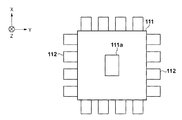
モールド上の領域111aには、製造誤差や熱変形などにより、例えば、倍率成分や台形成分などの成分を含む変形が生じている場合がある。そのため、モールド保持部113は、モールド111の側面における複数の箇所に力を加えてモールド111の変形を補正する補正部112を備えている。図2は、モールド111の変形を補正する補正部112の構成を示す図であり、モールド111を下(−Z方向)から見たときの図である。補正部112は、複数のアクチュエータを含み、図2に示す例では、モールド111の各辺に4個ずつのアクチュエータが備えられている。そして、各アクチュエータがモールド111の側面に個別に力を加えることにより、モールド上の領域111aの変形を補正することができる。補正部112のアクチュエータとしては、例えば、リニアモータやエアシリンダ、ピエゾアクチュエータなどが用いられる。
In the
照射部142は、基板上の樹脂を硬化させるために、基板上の樹脂にモールド111を介して光(紫外線)を照射する。照射部142は、例えば、基板上の樹脂を硬化させる光(紫外線)を射出する光源141と、光源141から射出された光の光路を折り曲げるミラー143とを含む。また、照射部142は、光源141から射出された光をインプリント処理において適切な光に調整する複数の光学素子(不図示)とを含みうる。樹脂供給部121は、基板上に樹脂(未硬化樹脂)を供給(塗布)する。上述したように、第1実施形態では、紫外線の照射によって硬化する性質を有する紫外線硬化樹脂が用いられているが、樹脂供給部121から基板上に供給される樹脂の種類は、半導体デバイスの製造工程における各種条件によって適宜選択されうる。また、樹脂供給部121の吐出ノズルから吐出される樹脂の量は、基板上の樹脂に転写されたパターンの厚さや密度などを考慮して適宜決定されうる。また、光源141から射出される光の波長は、樹脂の種類に応じて適宜決定されうる。
The
計測部114は、基板上に形成されたショット領域とパターンが形成されたモールド上の領域111aとの相対位置を計測する。例えば、ショット領域とモールド上の領域111aとには複数のアライメントマーク(以下、マーク)がそれぞれ設けられている。そして、計測部114は、複数のスコープを含み、各スコープがショット領域のマークとモールド上の領域111aのマークとを検出する。これにより、計測部114は、各スコープにおいて検出されたショット領域のマークとモールド上の領域111aのマークとの検出結果に基づいて、ショット領域とモールド上の領域111aとの相対位置を計測することができる。
The measuring
ここで、インプリント処理の際における、モールド111と基板101との位置合わせについて説明する。一般に、インプリント装置100におけるモールド111と基板101との位置合わせとしては、グローバルアライメント方式とダイバイダイアライメント方式とがある。グローバルアライメント方式とは、代表的な幾つかのショット領域(サンプルショット領域)に形成されたマークの検出結果を処理して決定した全てのショット領域の位置に基づいてアライメントを行うアライメント方式である。これに対し、ダイバイダイアライメント方式とは、基板上のショット領域ごとに、ショット領域に形成されたマークとモールドに形成されたマークとを光学的に検出して、基板101とモールド111との相対位置のずれを補正するアライメント方式である。第1実施形態では、ダイバイダイアライメント方式によるモールド111と基板101との位置合わせ方法について説明する。
Here, the alignment between the
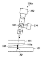
図3は、基板上のマーク321とモールド上のマーク311とを検出する計測部114のスコープ114aを示す図である。図3に示すように、モールド111は、パターンとマーク311とが形成された領域111aを含む。スコープ114aは、例えば、光を射出する光源330と、プリズム331と、撮像素子332と、複数の光学素子とを含みうる。光源330から射出される光は、基板上に供給された樹脂を硬化する光(紫外線)の波長とは異なる波長を有する。また、スコープ114aが傾いているのは、基板上に供給された樹脂を硬化させる光(紫外線)がモールド111の上方から照射されるため、その光(紫外線)の光路を確保するためである。スコープ114aは、光源330から射出された光を、ハーフプリズムや偏光ビームスプリッタなどで構成されたプリズム331で反射させて、モールド上のマーク311と基板上のマーク321とに照射する。モールド111で反射された光と基板101で反射された光は、プリズム331を透過して撮像素子332に入射する。これにより、モールド上のマーク311の像と基板上のマーク321の像とを撮像素子332に結像することができる。例えば、モールド上のマーク311と基板上のマーク321とが、互いにピッチの異なる格子パターンで構成される場合には、撮像素子332にモアレ像を結像することができる。撮像素子332に結像されたモアレ像は、モールド上のマーク311と基板上のマーク321との相対位置の差を拡大して投影しているため、モールド上のマーク311と基板上のマーク321との相対位置を精度よく検出することができる。また、モールド上のマーク311と基板上のマーク321として、例えば、Box in Boxのマークを用いてもよい。
FIG. 3 is a diagram showing the
このように構成された第1実施形態のインプリント装置100におけるインプリント処理について、図4を参照しながら説明する。まず、制御部150は、モールド111のパターンを転写すべき基板上の目標領域(例えば、インプリント処理が行われるショット領域)が樹脂供給部121の下に配置されるように基板ステージ106を制御して、基板101を移動させる。目標領域が樹脂供給部121の下に配置されると、制御部150は、目標領域に樹脂122(未硬化樹脂)を供給するように樹脂供給部121を制御する。そして、制御部150は、目標領域に樹脂122が供給された後、パターンが形成されたモールド上の領域111aの下に目標領域が配置されるように基板ステージ106を制御して、基板101を移動させる。このとき、モールド111と基板101との位置関係は、図4(a)に示す位置関係となる。
The imprint process in the
制御部150は、モールド上の領域111aの下に目標領域が配置されると、計測部114によりモールド上のマークと目標領域とのマークとをそれぞれ検出させて、モールド上の領域111aと目標領域との相対位置を計測する。そして、制御部150は、計測部114による計測結果に基づいて、モールド111と基板上の樹脂とが接触していない状態で基板ステージ106やモールド保持部113を駆動し、モールド上の領域111aと目標領域との位置合わせを行う。そして、制御部150は、モールド上の領域111aと目標領域との位置合わせを行った後、モールド111が−Z方向に移動するようにモールド保持部113を制御し、モールド111のパターンと基板上の樹脂122とを接触させる。このとき、モールド111と基板101との位置関係は、図4(b)に示す位置関係となる。
When the target area is arranged under the
制御部150は、モールド111のパターンと基板上の樹脂122とを接触させた状態で所定の時間を経過させる。これにより、基板上の樹脂122を、モールド111のパターンの隅々まで充填することができる。制御部150は、モールド111と基板上の樹脂122とが接触してから所定の時間が経過した後、基板上の樹脂122にモールド111を介して光(紫外線)を照射するように照射部142を制御する。そして、制御部150は、モールド111が+Z方向に移動するようにモールド保持部113を制御し、モールド111を基板上の樹脂122から剥離する。このとき、モールド111と基板101との位置関係は、図4(c)に示す位置関係となる。これにより、モールド111のパターンを基板上の樹脂122に転写することができる。
The
このように、第1実施形態のインプリント装置100では、モールド111と基板上の樹脂とが接触していない状態でモールド111と基板101との位置合わせ(モールド111の位置決め)が行われる。しかしながら、モールド111と基板上の樹脂とが接触していない状態でモールド111の位置決めを行うと、モールド111のパターンが、当該パターンを転写すべき基板上の目標領域(ショット領域)からずれて転写されてしまうことがある。そこで、第1実施形態のインプリント装置100は、基板101に転写されたモールド111のパターンが基板上の目標領域に対してXY方向(基板101の面に沿った面方向)にシフトする量を示すシフト量(補正値)を事前に取得する。モールド111と樹脂122とが接触していない状態で、モールド111と基板101との位置合わせを行った後に、モールド111を基板101に近づけて樹脂122に接触させる間に発生するシフト量を計測する。そして、インプリント装置100は、モールド111と基板上の樹脂とが接触していない状態において、計測部により計測されたモールド111のパターンを目標領域に対してシフト量だけずらしてモールド111と基板101との位置合わせを行う。これにより、モールド111のパターンが基板上の目標領域に対してずれて転写されることを抑制し、基板上の目標領域にモールド111のパターンを精度よく転写することができる。
As described above, in the
モールド111のパターンが目標領域からずれて転写されてしまう原因としては、例えば、モールド111と基板上の樹脂と接触させる過程におけるモールドのシフトと、計測部114における計測誤差とが想定される。前者においては、例えば、図5に示すように、基板101の周辺部に配置されたショット領域601(モールドのパターンの一部を転写できるショット領域)にモールドのパターンを転写する際に顕著になる。例えば、ショット領域601にモールド111のパターンを転写する際には、ショット領域601の四隅に配置された複数のマーク611〜614のうち、マーク614は用いずに、マーク611〜613のみを用いて位置合わせが行われる。そして、このようなショット領域601においては、転写性能を向上させるため、モールド111を基板101に対してわずかに傾けた状態で基板上の樹脂に接触させることがある。このようにモールド111を基板101に対して傾けた状態では、モールド111と基板上の樹脂とを接触させる過程によってモールド111のパターンが目標領域(基板の周辺部のショット領域)に対してシフトしてしまいうる。そのため、第1実施形態のインプリント装置100は、モールドを基板上の樹脂に接触させる過程においてモールドがシフトする量を示す第1シフト量を補正するための第1補正値を取得する。
As a cause of the pattern of the
後者においては、例えば、図3に示すように、計測部114のスコープ114aは傾けて配置されるため、モールド上のマークと基板上のマークとの相対位置を検出する際に計測誤差(計測騙され)が生じてしまいうる。このように計測部114の計測誤差が生じている場合では、モールド111のパターンと基板上の目標領域とを計測部114を用いて精度よく位置合わせしたとしても、モールドのパターンが目標領域に対してずれて転写されてしまう。そのため、第1実施形態のインプリント装置100は、計測部114の計測誤差に起因して生じる、基板101に転写されたモールド111のパターンが目標領域に対してシフトする量を示す第2シフト量を補正するための第2補正値を取得する。
In the latter case, for example, as shown in FIG. 3, the
第1実施形態のインプリント装置100は、モールド111と基板上の樹脂とが接触していない状態において、第1補正値と第2補正値とを用いてモールド111と基板101との位置合わせを行う。即ち、モールド111と基板上の樹脂とが接触していない状態において計測部114により計測されたモールド111のパターンが、目標領域に対して第1シフト量と第2シフト量との総量だけずれるようにモールド111と基板101との位置合わせが行われる。ここで、第1補正値および第2補正値は、基板上におけるショット領域ごとにそれぞれ取得されうる。以下では、複数のショット領域における第1補正値のマップを第1補正マップ、および複数のショット領域における第2補正値のマップを第2補正マップとする。第1実施形態のインプリント装置100は、制御部150により第1補正マップと第2補正マップを選択し、取得した第1補正マップと第2補正マップから第1補正値と第2補正値とを、目標ショット領域の位置に応じてそれぞれ抽出する。そして、インプリント装置100は、抽出した第1補正値と第2補正値とを用いて目標領域のインプリント処理を行う。これにより、目標領域にモールド111のパターンを精度よく転写することができる。また、第1実施形態のインプリント装置100では、モールド111と基板上の樹脂とが接触していない状態において、第1補正値と第2補正値との双方を用いてモールドと基板との位置合わせを行っているが、それに限られるものではない。例えば、第1補正値のみを用いてモールド111と基板101との位置合わせを行ってもよいし、第2補正値のみを用いてモールド111と基板101との位置合わせを行ってもよい。
The
ここで、第1補正マップと第2補正マップとの生成方法について説明する。まず、第1補正マップの生成方法について説明する。インプリント装置100は、モールド111の垂直方向(Z方向)への駆動の前後におけるモールド111の面方向(XY方向)における位置の変化を算出する。即ち、インプリント装置100(制御部150)は、モールド111と基板上の樹脂とが接触していない状態と接触している状態との双方において、モールド111のパターンとショット領域との相対位置を計測部114により計測させる。そして、インプリント装置100は、モールド111と樹脂とが接触していない状態で計測部114により計測された相対位置と、モールド111と樹脂とが接触している状態で計測部114により計測された相対位置との差を算出する。このように算出された相対位置の差が当該ショット領域の第1シフト量となり、この第1シフト量が第1補正値として設定される。そして、第1補正値を設定する工程を複数のショット領域において繰り返すことにより、第1補正マップが生成される。第1補正マップは、基板101のロットごとに生成されうる。
Here, a method of generating the first correction map and the second correction map will be described. First, a method for generating the first correction map will be described. The
次に、第2補正マップの生成方法について説明する。インプリント装置100(制御部150)は、モールド111と基板上の樹脂とが接触している状態においてモールド111のパターンとショット領域との相対位置を計測部114により計測させ、モールド111のパターンを基板101に転写する。そして、インプリント装置100は、モールド111と樹脂とが接触している状態で計測部114により計測された相対位置と、基板101に転写されたモールド111のパターンとショット領域との相対位置との差を算出する。基板101に転写されたパターンとショット領域との相対位置は、インプリント装置100に備えられた計測部114とは異なる検出部を用いて計測することができる。検出部としては、例えば、モールド111を通過せずに基板上のマークを検出することができるスコープ(オフアクシススコープ)が用いられうる。また、基板101に形成されたパターンとショット領域との相対位置は、インプリント装置100の外部の重ね合わせ検査装置を用いて計測されてもよい。このように算出された相対位置の差が当該ショット領域の第2シフト量となり、この第2シフト量が第2補正値として設定される。そして、第2補正値を設定する工程を複数のショット領域において繰り返すことにより、第2補正マップが生成される。第2補正マップは、例えばダミー基板を用いて、上述した方法により生成されうるが、回路パターンやレジストの特性などからシミュレーションすることによって生成されてもよい。また、第2補正マップは、第1補正マップと同様に、基板101のロットごとに生成されうる。
Next, a method for generating the second correction map will be described. The imprint apparatus 100 (control unit 150) causes the
ここで、補正マップ(第1補正マップや第2補正マップ)の一例を図6に示す。図6に示す補正マップは、基板上における複数のショット領域の各々における位置に応じて番号(Shot No)が割り振られており、各ショット領域に対する補正量(第1補正量や第2補正量)が含まれるように生成されている。補正量は、例えば以下に示す成分ごとの補正量を含みうる。
・XY方向のシフト成分の補正量(Shift_X,Shift_Y)
・XY方向の回転成分の補正量(Rot_X,Rot_Y)
・XY方向の倍率成分の補正量(Mag_X,Mag_Y)
・XY方向の台形成分の補正量(Trap_X,Trap_Y)
また、第1実施形態のインプリント装置100では、第1補正マップおよび第2補正マップは、制御部150によって生成されているが、それに限られるものではなく、例えば、インプリント装置100の外部のコンピュータなどによって生成されてもよい。
Here, an example of a correction map (a first correction map or a second correction map) is shown in FIG. The correction map shown in FIG. 6 is assigned a number (Shot No) according to the position in each of a plurality of shot areas on the substrate, and the correction amount (first correction amount or second correction amount) for each shot region. Has been generated to include. The correction amount can include a correction amount for each component shown below, for example.
-Correction amount of shift component in XY direction (Shift_X, Shift_Y)
-XY rotation component correction amount (Rot_X, Rot_Y)
-XY direction magnification component correction amount (Mag_X, Mag_Y)
-Correction amount for trapezoid formation in XY direction (Trap_X, Trap_Y)
In the
以下に、第1実施形態のインプリント装置100において、モールド111のパターンを基板上のショット領域(目標領域)に転写するインプリント処理について、図7を参照しながら説明する。図7は、モールド111のパターンを基板上の目標領域に転写するインプリント処理における動作シーケンスを示すフローチャートである。
Hereinafter, an imprint process in which the pattern of the
S701では、制御部150は、基板101のロットごとに生成された複数の第1補正マップおよび複数の第2補正マップの中から、インプリント処理を行う基板101のロットに応じた第1補正マップおよび第2補正マップを選択する。S702では、制御部150は、この後の工程においてモールド111と基板101との相対位置を計測することを容易にするため、基板101の位置とモールド111の位置とを装置座標を基準としてそれぞれ個別に計測する。具体的には、制御部150は、計測部114を用いて基板上における複数のマークを検出して、基板上における各ショット領域の位置を計測するとともに、モールド上における複数のマークを検出してモールド111の位置を計測する。このように、各ショット領域の位置とモールド111の位置とを装置座標を基準としてそれぞれ個別に計測することにより、モールド111と基板101との相対位置の計測を高精度に行うことができる。
In step S <b> 701, the
S703では、制御部150は、ショット領域が樹脂供給部121の下に配置されるように基板ステージ106を制御して、基板101を移動させる。S704では、制御部150は、ショット領域に樹脂(未硬化樹脂)を供給するように樹脂供給部121を制御する。S705では、制御部150は、樹脂が供給されたショット領域がモールド111のパターンの下に配置されるように基板ステージ106を制御して、基板101を移動させる。
In step S <b> 703, the
S706では、制御部150は、モールド111と基板上の樹脂とが接触していない状態において、モールド111のパターンとショット領域との相対位置を計測部114に計測させる。これにより、モールド111のパターンとショット領域との相対位置を、例えば、XY方向のシフト成分、回転成分、倍率成分および台形成分について取得することができる。S707では、制御部150は、S701において取得した第1補正マップおよび第2補正マップの中から、インプリント処理を行うショット領域に応じた第1補正量および第2補正量をそれぞれ抽出する。そして、制御部150は、計測部114により計測されたモールド111のパターンがショット領域に対して第1シフト量と第2シフト量の総量だけずれるように、第1補正量と第2補正量とを用いてモールド111と基板101との位置合わせを行う。モールド111と基板101との位置合わせは、例えば、基板ステージ106を駆動させて基板101を移動および回転させたり、モールド保持部113を駆動させてモールド111を移動および回転させたりすることによって行われる。このとき、補正部112によってモールド111の側面に力を加えて、モールド上の領域111aを変形させてもよい。これにより、モールド111のパターンを基板101に転写した際において、基板101に転写されたモールド111のパターンとショット領域との相対位置を許容範囲に収めることができる。
In step S <b> 706, the
S708では、制御部150は、面方向(XY方向)と直交する垂直方向(Z方向)にモールド111を駆動して基板上の樹脂とが接触するようにモールド保持部113を制御する。S709では、制御部150は、モールド111を接触させた樹脂に対して紫外線を照射するように照射部142を制御し、当該樹脂を硬化させる。S710では、制御部150は、モールド111を基板上の樹脂から剥離する(離型する)ようにモールド保持部113を制御する。S711では、制御部150は、引き続きモールド111のパターンを転写するショット領域(次のショット領域)が基板上にあるか否かの判定を行う。次のショット領域がある場合はS703に進み、次のショット領域がない場合は、1枚の基板におけるインプリント処理を終了する。
In S708, the
上述したように、第1実施形態のインプリント装置100では、モールド111と基板上の樹脂とが接触していない状態において、モールド111と基板101との位置合わせが行われる。このとき、インプリント装置100は、計測部114により計測されたモールド111のパターンが目標領域(ショット領域)に対して第1シフト量と第2シフト量の総量だけずれるように、第1補正値と第2補正とを用いてモールド111の位置決めを行う。これにより、インプリント装置100は、モールド111のパターンを目標領域に高精度に転写することができる。また、インプリント装置100は、モールド111と基板上の樹脂とが接触していない状態においてモールド111と基板101との位置合わせを行うことができるため、スループットの向上も図れる。
As described above, in the
ここで、第1実施形態では、基板上に形成されたショット領域にモールド111のパターンを転写する場合について説明したが、これに限られるものではない。例えば、ショット領域が形成されていない基板にモールドのパターンを転写する場合にも本発明を適用することができる。この場合、目標領域は、基板上に形成されたショット領域ではなく、例えば、装置座標を基準として管理されうる。また、第1実施形態では、ダイバイダイアライメント方式を採用してモールド111と基板101との位置合わせを行う場合について説明した。しかしながら、これに限られるものではなく、グローバルアライメント方式を採用してモールドと基板との位置合わせを行う場合にも本発明を適用することができる
Here, in the first embodiment, the case where the pattern of the
<第2実施形態>
本発明の第2実施形態のインプリント装置について説明する。第1実施形態のインプリント装置100では、モールド111と基板上の樹脂とが接触していない状態において、第1補正値と第2補正値とを用いてモールド111と基板101との位置合わせが行われた。一方で、第2実施形態のインプリント装置では、モールド111と基板上の樹脂とが接触していない状態において、第1補正値のみを用いてモールド111と基板101との位置合わせが行われる。そして、モールド111と基板上の樹脂とが接触している状態において、第2補正値を用いてモールド111と基板との位置合わせが行われる。ここで、第2実施形態のインプリント装置は、第1実施形態のインプリント装置と装置構成が同じであるため、ここでは装置構成についての説明を省略する。
Second Embodiment
An imprint apparatus according to a second embodiment of the present invention will be described. In the
以下に、第2実施形態のインプリント装置において、モールド111のパターンを基板上のショット領域(目標領域)に転写するインプリント処理について、図8を参照しながら説明する。図8は、モールド111のパターンを基板上のショット領域に転写するインプリント処理における動作シーケンスを示すフローチャートである。
The imprint process for transferring the pattern of the
図8におけるS801〜S806は、図6におけるS701〜S706と同じであるため、ここでは説明を省略する。S807では、制御部150は、S801において取得した第1補正マップの中から、インプリント処理を行うショット領域に応じた第1補正値を抽出する。そして、制御部150は、計測部114により計測されたモールド111のパターンがショット領域に対して第1シフト量だけずれるように、第1補正値を用いてモールド111と基板101との位置合わせを行う。S808では、制御部150は、面方向(XY方向)と直交する垂直方向(Z方向)にモールド111を駆動してモールド111と基板上の樹脂とが接触するようにモールド保持部113を制御する。S809では、制御部150は、S801において取得した第2補正マップの中から、インプリント処理を行うショット領域に応じた第2補正値を抽出する。そして、制御部150は、計測部114により計測されたモールド111のパターンがショット領域に対して第2シフト量だけずれるように、第2補正値を用いてモールド111と基板101との位置合わせを行う。これにより、モールド111のパターンを基板101に転写した際において、基板101に転写されたモールド111のパターンとショット領域との相対位置を許容範囲に収めることができる。S810では、制御部150は、モールド111を接触させた樹脂に対して紫外線を照射するように照射部142を制御し、当該樹脂を硬化させる。S811では、制御部150は、モールド111と基板101との距離を長くしてモールド111を基板上の樹脂から剥離する(離型する)ようにモールド保持部113を制御する。S812では、制御部150は、引き続きモールド111のパターンを転写するショット領域(次のショット領域)が基板上にあるか否かの判定を行う。次のショット領域がある場合にはS803に進み、次のショット領域がない場合には、1枚の基板におけるインプリント処理を終了する。
Since S801 to S806 in FIG. 8 are the same as S701 to S706 in FIG. In step S807, the
上述したように、第2実施形態のインプリント装置では、モールド111と基板上の樹脂とが接触していない状態において、第1補正値を用いてモールド111と基板101との位置合わせが行われる。そして、モールド111と基板上の樹脂とが接触している状態において、第2補正値を用いてモールド111と基板101との位置合わせが行われる。これにより、第2実施形態のインプリント装置は、第1実施形態のインプリント装置100と同様に、モールド111のパターンを目標領域に高精度に転写することができる。また、第2実施形態のインプリント装置は、モールド111と基板上の樹脂とが接触している状態においては第2シフト量を補正するだけでよい。そのため、モールド111と樹脂とが接触している状態おいてモールド111と基板101との相対位置を変更する量を低減することができ、スループットの向上が図れる。
As described above, in the imprint apparatus according to the second embodiment, the
<物品の製造方法の実施形態>
本発明の実施形態にかかる物品の製造方法は、例えば、半導体デバイス等のマイクロデバイスや微細構造を有する素子等の物品を製造するのに好適である。本実施形態の物品の製造方法は、基板に塗布された樹脂に上記のインプリント装置を用いてパターンを形成する工程(基板にインプリント処理を行う工程)と、かかる工程でパターンが形成された基板を加工する工程とを含む。更に、かかる製造方法は、他の周知の工程(酸化、成膜、蒸着、ドーピング、平坦化、エッチング、レジスト剥離、ダイシング、ボンディング、パッケージング等)を含む。本実施形態の物品の製造方法は、従来の方法に比べて、物品の性能・品質・生産性・生産コストの少なくとも1つにおいて有利である。
<Embodiment of Method for Manufacturing Article>
Method for producing such articles to an embodiment of the present invention, for example, is suitable for producing articles such as devices having a micro-device and the microstructure such as semiconductor devices. In the method for manufacturing an article according to the present embodiment, a pattern is formed in a step of forming a pattern on the resin applied to the substrate using the above-described imprint apparatus (step of performing imprint processing on the substrate). Processing the substrate. Further, the manufacturing method includes other well-known steps (oxidation, film formation, vapor deposition, doping, planarization, etching, resist stripping, dicing, bonding, packaging, and the like). The method for manufacturing an article according to the present embodiment is advantageous in at least one of the performance, quality, productivity, and production cost of the article as compared with the conventional method.
以上、本発明の好ましい実施形態について説明したが、本発明はこれらの実施形態に限定されないことはいうまでもなく、その要旨の範囲内で種々の変形および変更が可能である。 As mentioned above, although preferred embodiment of this invention was described, it cannot be overemphasized that this invention is not limited to these embodiment, A various deformation | transformation and change are possible within the range of the summary.
Claims (10)
前記基板の面に沿った面方向における前記モールドと前記基板との相対位置を計測する計測部と、
前記計測部での計測結果に基づいて前記面方向における前記モールドと前記基板との位置合わせを行う第1処理と、前記第1処理の後に、前記モールドと前記インプリント材とを接触させるように前記モールドと前記基板とを相対的に駆動する第2処理とを制御する制御部と、
を含み、
前記制御部は、
前記第2処理での前記モールドと前記基板との相対的な駆動に起因して前記モールドが前記目標領域に対して前記面方向にシフトしうる量を示す第1シフト量と、前記計測部での計測誤差に起因して前記基板上に転写された前記モールドのパターンが前記目標領域に対してシフトしうる量を示す第2シフト量とを示す情報を取得し、
前記第1処理の際、前記情報に基づいて、前記モールドのパターンが前記目標領域に対して前記第1シフト量と前記第2シフト量との総量だけずれるように前記モールドと前記基板との位置合わせを制御する、ことを特徴とするインプリント装置。 An imprint apparatus for forming a pattern in a target area of the substrate by bringing a mold and an imprint material on the substrate into contact with each other,
A measurement unit that measures a relative position between the mold and the substrate in a surface direction along the surface of the substrate;
A first process for aligning the mold and the substrate in the surface direction based on the measurement result of the measurement unit, and the mold and the imprint material are brought into contact after the first process. A control unit for controlling a second process for relatively driving the mold and the substrate ;
Including
The controller is
A first shift amount indicating the amount that can be shifted in the surface direction the mold due to the relative drive between the mold and the substrate relative to the target region in the second processing, in the measuring section Obtaining information indicating a second shift amount indicating an amount by which the pattern of the mold transferred onto the substrate due to the measurement error can be shifted with respect to the target region;
In the first process, based on the information, the position of the mold and the substrate is such that the pattern of the mold is shifted from the target area by the total amount of the first shift amount and the second shift amount. An imprint apparatus that controls alignment.
前記制御部は、前記第1シフト量をショット領域ごとに取得する、ことを特徴とする請求項1乃至4のうちいずれか1項に記載のインプリント装置。 The substrate includes a plurality of shot regions,
Wherein the control unit, the imprint apparatus according to any one of claims 1 to 4 to obtain said first shift amount for each shot region, it is characterized.
前記制御部は、前記第2シフト量をショット領域ごとに取得する、ことを特徴とする請求項1乃至5のうちいずれか1項に記載のインプリント装置。 The substrate includes a plurality of shot regions,
Wherein the control unit, the second acquiring shift amount for each shot region, it imprint apparatus according to any one of claims 1 to 5, characterized in.
前記基板の面に沿った面方向における前記モールドと前記基板との相対位置を計測する計測部と、
前記計測部での計測結果に基づいて前記面方向における前記モールドと前記基板との位置合わせを行う第1処理と、前記第1処理の後に、前記モールドと前記インプリント材とを接触させるように前記モールドと前記基板とを相対的に駆動する第2処理と、前記第2処理の後、前記モールドと前記インプリント材とが接触している状態で、前記計測部での計測結果に基づいて前記面方向における前記モールドと前記基板との位置合わせを行う第3処理とを制御する制御部と、
を含み、
前記制御部は、
前記第2処理での前記モールドと前記基板との相対的な駆動に起因して前記モールドが前記目標領域に対して前記面方向にシフトしうる量を示す第1シフト量と、前記計測部での計測誤差に起因して前記基板上に転写された前記モールドのパターンが前記目標領域に対してシフトしうる量を示す第2シフト量とを示す情報を取得し、
前記第1処理の際、前記情報に基づいて、前記モールドのパターンが前記目標領域に対して前記第1シフト量だけずれるように前記モールドと前記基板との位置合わせを制御し、
前記第3処理の際、前記情報に基づいて、前記モールドのパターンが前記目標領域に対して前記第2シフト量だけずれるように前記モールドと前記基板との位置合わせを制御する、ことを特徴とするインプリント装置。 An imprint apparatus for forming a pattern in a target area of the substrate by bringing a mold and an imprint material on the substrate into contact with each other,
A measurement unit that measures a relative position between the mold and the substrate in a surface direction along the surface of the substrate;
A first process for aligning the mold and the substrate in the surface direction based on the measurement result of the measurement unit, and the mold and the imprint material are brought into contact after the first process. Based on the measurement result of the measurement unit in a state in which the mold and the imprint material are in contact with each other after the second process for relatively driving the mold and the substrate. A control unit that controls a third process for aligning the mold and the substrate in the surface direction ;
Including
The controller is
A first shift amount indicating the amount that can be shifted in the surface direction the mold due to the relative drive between the mold and the substrate relative to the target region in the second processing, in the measuring section Obtaining information indicating a second shift amount indicating an amount by which the pattern of the mold transferred onto the substrate due to the measurement error can be shifted with respect to the target region;
In the first process, based on the information, the alignment of the mold and the substrate is controlled so that the pattern of the mold is shifted by the first shift amount with respect to the target region,
In the third process, based on the information, the alignment of the mold and the substrate is controlled such that the pattern of the mold is shifted by the second shift amount with respect to the target region. Imprint device to do.
前記ステップでパターンが形成された前記基板を加工するステップと、
を含む、ことを特徴とする物品の製造方法。 Forming a pattern on a substrate using the imprint apparatus according to any one of claims 1 to 7 ,
Processing the substrate on which the pattern is formed in the step;
A method for producing an article comprising:
前記基板の面に沿った面方向における前記モールドと前記基板との相対位置を計測部に計測させた結果に基づいて、前記モールドと前記基板との位置合わせを行う第1処理と、
前記第1処理の後に、前記モールドと前記インプリント材とを接触させるように前記モールドと前記基板とを相対的に駆動する第2処理と、
を含み、
前記第1処理では、
前記第2処理での前記モールドと前記基板との相対的な駆動に起因して前記モールドが前記目標領域に対して前記面方向にシフトしうる量を示す第1シフト量と、前記計測部での計測誤差に起因して前記基板上に転写された前記モールドのパターンが前記目標領域に対してシフトしうる量を示す第2シフト量とを示す情報を取得し、
前記情報に基づいて、前記モールドのパターンが前記目標領域に対して前記第1シフト量と前記第2シフト量との総量だけずれるように前記モールドと前記基板との位置合わせを制御する、ことを特徴とするインプリント方法。 An imprint method for forming a pattern in a target area of the substrate by contacting a mold and an imprint material on the substrate,
A first process for aligning the mold and the substrate based on a result of measuring a relative position between the mold and the substrate in a surface direction along the surface of the substrate;
A second process for relatively driving the mold and the substrate so that the mold and the imprint material are brought into contact with each other after the first process;
Including
In the first process,
A first shift amount indicating the amount that can be shifted in the surface direction the mold due to the relative drive between the mold and the substrate relative to the target region in the second processing, in the measuring section Obtaining information indicating a second shift amount indicating an amount by which the pattern of the mold transferred onto the substrate due to the measurement error can be shifted with respect to the target region;
Based on the information, the alignment of the mold and the substrate is controlled so that the pattern of the mold is shifted from the target area by the total amount of the first shift amount and the second shift amount. A characteristic imprint method.
前記基板の面に沿った面方向における前記モールドと前記基板との相対位置を計測部に計測させた結果に基づいて、前記モールドと前記基板との位置合わせを行う第1処理と、
前記第1処理の後に、前記モールドと前記インプリント材とを接触させるように前記モールドと前記基板とを相対的に駆動する第2処理と、
前記第2処理の後、前記モールドと前記インプリント材とが接触している状態で、前記面方向における前記モールドと前記基板との相対位置を前記計測部に計測させた結果に基づいて、前記モールドと前記基板との位置合わせを行う第3処理と、
を含み、
前記第1処理では、前記第2処理での前記モールドと前記基板との相対的な駆動に起因して前記モールドが前記目標領域に対して前記面方向にシフトしうる量を示す第1シフト量を取得し、前記モールドのパターンが前記目標領域に対して前記第1シフト量だけずれるように前記モールドと前記基板との位置合わせを制御し、
前記第3処理では、前記計測部での計測誤差に起因して前記基板上に転写された前記モールドのパターンが前記目標領域に対してシフトしうる量を示す第2シフト量を取得し、前記モールドのパターンが前記目標領域に対して前記第2シフト量だけずれるように前記モールドと前記基板との位置合わせを制御する、ことを特徴とするインプリント方法。 An imprint method for forming a pattern in a target area of the substrate by contacting a mold and an imprint material on the substrate,
A first process for aligning the mold and the substrate based on a result of measuring a relative position between the mold and the substrate in a surface direction along the surface of the substrate;
A second process for relatively driving the mold and the substrate so that the mold and the imprint material are brought into contact with each other after the first process;
After the second treatment , based on the result of having the measurement unit measure the relative position between the mold and the substrate in the surface direction in a state where the mold and the imprint material are in contact with each other , A third process for aligning the mold and the substrate;
Including
Wherein in the first process, the mold and relative the first shift amount indicating the amount that can be shifted in the surface direction the mold due the to the target area to the drive with the substrate in the second processing And controlling the alignment of the mold and the substrate so that the pattern of the mold is shifted by the first shift amount with respect to the target area,
In the third process, a second shift amount indicating an amount by which the pattern of the mold transferred onto the substrate due to a measurement error in the measurement unit can be shifted with respect to the target region is obtained, The imprint method is characterized in that the alignment of the mold and the substrate is controlled so that the pattern of the mold is shifted by the second shift amount with respect to the target area.
Priority Applications (6)
| Application Number | Priority Date | Filing Date | Title |
|---|---|---|---|
| JP2013127986A JP6271875B2 (en) | 2013-06-18 | 2013-06-18 | Imprint apparatus, imprint method, and article manufacturing method |
| KR1020140069912A KR101863987B1 (en) | 2013-06-18 | 2014-06-10 | Imprint apparatus, imprint method, and method of manufacturing article |
| US14/302,566 US9971256B2 (en) | 2013-06-18 | 2014-06-12 | Imprint apparatus, imprint method, and method of manufacturing article |
| CN201811028474.1A CN109062004B (en) | 2013-06-18 | 2014-06-13 | Imprint apparatus, imprint method, and method of manufacturing article |
| CN201410262315.3A CN104238263B (en) | 2013-06-18 | 2014-06-13 | Imprinting apparatus, method for stamping and the method for manufacturing article |
| KR1020180060464A KR101981006B1 (en) | 2013-06-18 | 2018-05-28 | Imprint apparatus, imprint method, and method of manufacturing article |
Applications Claiming Priority (1)
| Application Number | Priority Date | Filing Date | Title |
|---|---|---|---|
| JP2013127986A JP6271875B2 (en) | 2013-06-18 | 2013-06-18 | Imprint apparatus, imprint method, and article manufacturing method |
Related Child Applications (1)
| Application Number | Title | Priority Date | Filing Date |
|---|---|---|---|
| JP2017254394A Division JP6560736B2 (en) | 2017-12-28 | 2017-12-28 | Imprint apparatus, imprint method, and article manufacturing method |
Publications (3)
| Publication Number | Publication Date |
|---|---|
| JP2015002344A JP2015002344A (en) | 2015-01-05 |
| JP2015002344A5 JP2015002344A5 (en) | 2016-08-04 |
| JP6271875B2 true JP6271875B2 (en) | 2018-01-31 |
Family
ID=52018554
Family Applications (1)
| Application Number | Title | Priority Date | Filing Date |
|---|---|---|---|
| JP2013127986A Active JP6271875B2 (en) | 2013-06-18 | 2013-06-18 | Imprint apparatus, imprint method, and article manufacturing method |
Country Status (4)
| Country | Link |
|---|---|
| US (1) | US9971256B2 (en) |
| JP (1) | JP6271875B2 (en) |
| KR (2) | KR101863987B1 (en) |
| CN (2) | CN104238263B (en) |
Families Citing this family (10)
| Publication number | Priority date | Publication date | Assignee | Title |
|---|---|---|---|---|
| JP6333039B2 (en) | 2013-05-16 | 2018-05-30 | キヤノン株式会社 | Imprint apparatus, device manufacturing method, and imprint method |
| JP6315904B2 (en) * | 2013-06-28 | 2018-04-25 | キヤノン株式会社 | Imprint method, imprint apparatus, and device manufacturing method |
| JP6138189B2 (en) | 2015-04-08 | 2017-05-31 | キヤノン株式会社 | Imprint apparatus and article manufacturing method |
| JP6726987B2 (en) * | 2016-03-17 | 2020-07-22 | キヤノン株式会社 | Imprint apparatus and article manufacturing method |
| JP7060961B2 (en) * | 2018-01-05 | 2022-04-27 | キヤノン株式会社 | Imprinting equipment, imprinting method and article manufacturing method |
| JP7116552B2 (en) * | 2018-02-13 | 2022-08-10 | キヤノン株式会社 | IMPRINT APPARATUS AND ARTICLE MANUFACTURING METHOD |
| JP7134717B2 (en) | 2018-05-31 | 2022-09-12 | キヤノン株式会社 | Imprinting apparatus, imprinting method and article manufacturing method |
| JP7278135B2 (en) * | 2019-04-02 | 2023-05-19 | キヤノン株式会社 | Imprint apparatus and article manufacturing method |
| JP7433861B2 (en) * | 2019-11-27 | 2024-02-20 | キヤノン株式会社 | Imprint equipment, imprint method, article manufacturing method, substrate, and mold |
| US20230127984A1 (en) * | 2021-10-25 | 2023-04-27 | Canon Kabushiki Kaisha | Apparatus and method for optimizing actuator forces |
Family Cites Families (11)
| Publication number | Priority date | Publication date | Assignee | Title |
|---|---|---|---|---|
| JP2006165371A (en) | 2004-12-09 | 2006-06-22 | Canon Inc | Transfer apparatus and device manufacturing method |
| JP2010283207A (en) | 2009-06-05 | 2010-12-16 | Toshiba Corp | Pattern forming device and pattern forming method |
| JP5662741B2 (en) * | 2009-09-30 | 2015-02-04 | キヤノン株式会社 | Imprint apparatus and article manufacturing method |
| KR101413873B1 (en) * | 2010-06-16 | 2014-06-30 | 아사히 가세이 가부시키가이샤 | Roller mold manufacturing device and manufacturing method |
| JP2012084732A (en) | 2010-10-13 | 2012-04-26 | Canon Inc | Imprint method and device |
| JP2012178470A (en) | 2011-02-25 | 2012-09-13 | Canon Inc | Imprint device and device manufacturing method |
| JP2013021194A (en) | 2011-07-12 | 2013-01-31 | Canon Inc | Imprint device and manufacturing method of article |
| JP5864929B2 (en) * | 2011-07-15 | 2016-02-17 | キヤノン株式会社 | Imprint apparatus and article manufacturing method |
| JP6004738B2 (en) * | 2011-09-07 | 2016-10-12 | キヤノン株式会社 | Imprint apparatus and article manufacturing method using the same |
| JP6140966B2 (en) * | 2011-10-14 | 2017-06-07 | キヤノン株式会社 | Imprint apparatus and article manufacturing method using the same |
| JP6159072B2 (en) * | 2011-11-30 | 2017-07-05 | キヤノン株式会社 | Imprint apparatus, imprint method, and article manufacturing method |
-
2013
- 2013-06-18 JP JP2013127986A patent/JP6271875B2/en active Active
-
2014
- 2014-06-10 KR KR1020140069912A patent/KR101863987B1/en active IP Right Grant
- 2014-06-12 US US14/302,566 patent/US9971256B2/en active Active
- 2014-06-13 CN CN201410262315.3A patent/CN104238263B/en active Active
- 2014-06-13 CN CN201811028474.1A patent/CN109062004B/en active Active
-
2018
- 2018-05-28 KR KR1020180060464A patent/KR101981006B1/en active IP Right Grant
Also Published As
| Publication number | Publication date |
|---|---|
| CN104238263A (en) | 2014-12-24 |
| CN109062004B (en) | 2022-03-29 |
| KR101981006B1 (en) | 2019-05-21 |
| US20140367874A1 (en) | 2014-12-18 |
| CN109062004A (en) | 2018-12-21 |
| KR20140147015A (en) | 2014-12-29 |
| KR20180062449A (en) | 2018-06-08 |
| JP2015002344A (en) | 2015-01-05 |
| KR101863987B1 (en) | 2018-07-04 |
| CN104238263B (en) | 2018-09-14 |
| US9971256B2 (en) | 2018-05-15 |
Similar Documents
| Publication | Publication Date | Title |
|---|---|---|
| JP6271875B2 (en) | Imprint apparatus, imprint method, and article manufacturing method | |
| US9261802B2 (en) | Lithography apparatus, alignment method, and method of manufacturing article | |
| JP5960198B2 (en) | Pattern forming method, lithographic apparatus, lithographic system, and article manufacturing method | |
| US9442370B2 (en) | Imprinting method, imprinting apparatus, and device manufacturing method | |
| JP6362399B2 (en) | Imprint apparatus, imprint method, and article manufacturing method | |
| JP6418773B2 (en) | Imprint apparatus, imprint method, and article manufacturing method | |
| JP6506521B2 (en) | Imprint method, imprint apparatus, and method of manufacturing article | |
| JP5723337B2 (en) | Pattern forming method and pattern forming apparatus | |
| JP6029268B2 (en) | Imprint apparatus and article manufacturing method using the same | |
| KR102032095B1 (en) | Method of curing uncured material and method of manufacturing article | |
| JP6029494B2 (en) | Imprint method, imprint apparatus, and article manufacturing method using the same | |
| JP2005101201A (en) | Nano-imprint system | |
| JP6497954B2 (en) | Imprint method, imprint apparatus, and article manufacturing method | |
| JP6555868B2 (en) | Pattern forming method and article manufacturing method | |
| JP2010080631A (en) | Stamping device and method of manufacturing article | |
| JP6329353B2 (en) | Imprint apparatus and article manufacturing method | |
| JP6560736B2 (en) | Imprint apparatus, imprint method, and article manufacturing method | |
| JP2016021440A (en) | Imprint device, imprint method, and method of manufacturing article | |
| JP6792669B2 (en) | Pattern formation method, lithography equipment, lithography system and article manufacturing method | |
| KR20210065854A (en) | Imprinting apparatus, imprinting method, method for producing article, substrate, and mold | |
| JP2020194892A (en) | Imprint apparatus and article manufacturing method |
Legal Events
| Date | Code | Title | Description |
|---|---|---|---|
| A521 | Request for written amendment filed |
Free format text: JAPANESE INTERMEDIATE CODE: A523 Effective date: 20160614 |
|
| A621 | Written request for application examination |
Free format text: JAPANESE INTERMEDIATE CODE: A621 Effective date: 20160614 |
|
| A977 | Report on retrieval |
Free format text: JAPANESE INTERMEDIATE CODE: A971007 Effective date: 20170317 |
|
| A131 | Notification of reasons for refusal |
Free format text: JAPANESE INTERMEDIATE CODE: A131 Effective date: 20170327 |
|
| A521 | Request for written amendment filed |
Free format text: JAPANESE INTERMEDIATE CODE: A523 Effective date: 20170523 |
|
| A131 | Notification of reasons for refusal |
Free format text: JAPANESE INTERMEDIATE CODE: A131 Effective date: 20170929 |
|
| A521 | Request for written amendment filed |
Free format text: JAPANESE INTERMEDIATE CODE: A523 Effective date: 20171108 |
|
| TRDD | Decision of grant or rejection written | ||
| A01 | Written decision to grant a patent or to grant a registration (utility model) |
Free format text: JAPANESE INTERMEDIATE CODE: A01 Effective date: 20171204 |
|
| A61 | First payment of annual fees (during grant procedure) |
Free format text: JAPANESE INTERMEDIATE CODE: A61 Effective date: 20171228 |
|
| R151 | Written notification of patent or utility model registration |
Ref document number: 6271875 Country of ref document: JP Free format text: JAPANESE INTERMEDIATE CODE: R151 |