まず、遊技機の一例であるパチンコ遊技機1の全体の構成について説明する。図1はパチンコ遊技機1を正面からみた正面図である。
First, the overall configuration of a pachinko gaming machine 1 that is an example of a gaming machine will be described. FIG. 1 is a front view of the pachinko gaming machine 1 as seen from the front.
パチンコ遊技機1は、図1、図2及び図4に示すように、縦長の方形枠状に形成された外枠100と、外枠100の内側に開閉可能に取り付けられ、後述する遊技盤6が取り付けられる遊技枠110と、遊技枠110の前面を開閉可能な額縁状に形成されたガラス扉枠2と、遊技枠110の前面におけるガラス扉枠2の下方を開閉可能な下扉枠103と、から主に構成される。
As shown in FIGS. 1, 2 and 4, the pachinko gaming machine 1 is provided with an outer frame 100 formed in a vertically long rectangular frame shape, and is attached to the inside of the outer frame 100 so as to be openable and closable. A game frame 110 to which the game frame 110 is attached, a glass door frame 2 formed in a frame shape capable of opening and closing the front of the game frame 110, and a lower door frame 103 capable of opening and closing the lower side of the glass door frame 2 on the front of the game frame 110 , Mainly composed of.
下扉枠103の表面には打球供給皿(上皿)3がある。下扉枠103の下方には、打球供給皿3に収容しきれない遊技球を貯留する余剰球受皿4や、打球を発射する打球操作ハンドル(操作ノブ)5が設けられている。また、ガラス扉枠2の背面には、遊技盤6が遊技枠110に対して着脱可能に取り付けられている。なお、遊技盤6は、それを構成する板状の合成樹脂板と、その合成樹脂板に取り付けられた種々の部品とを含む構造体であり、これらの詳細な構造に関しては後述することとする。また、遊技盤6の前面には、打ち込まれた遊技球が流下可能な遊技領域7が形成されている。
A hitting ball supply tray (upper plate) 3 is provided on the surface of the lower door frame 103. Below the lower door frame 103, there are provided an extra ball receiving tray 4 for storing game balls that cannot be accommodated in the hit ball supply tray 3, and a hitting operation handle (operation knob) 5 for emitting hitting balls. The game board 6 is detachably attached to the game frame 110 on the back surface of the glass door frame 2. The game board 6 is a structure including a plate-like synthetic resin plate constituting the game board and various components attached to the synthetic resin plate, and the detailed structure thereof will be described later. . In addition, a game area 7 is formed on the front surface of the game board 6 in which a game ball that has been struck can flow down.
遊技領域7の中央付近には、液晶表示装置(LCD)で構成された演出表示装置9が設けられている。演出表示装置9では、第1特別図柄または第2特別図柄の可変表示に同期した演出図柄(飾り図柄)の可変表示(変動)が行われる。よって、演出表示装置9は、識別情報としての演出図柄(飾り図柄)の可変表示を行う可変表示装置に相当する。演出表示装置9は、演出制御基板80に搭載されている演出制御用マイクロコンピュータによって制御される。演出制御用マイクロコンピュータが、第1特別図柄表示器8a(図3参照)で第1特別図柄の可変表示が実行されているときに、その可変表示に伴って演出表示装置9で演出表示を実行させ、第2特別図柄表示器8b(図3参照)で第2特別図柄の可変表示が実行されているときに、その可変表示に伴って演出表示装置9で演出表示を実行させるので、遊技の進行状況を把握しやすくすることができる。
An effect display device 9 composed of a liquid crystal display device (LCD) is provided near the center of the game area 7. In the effect display device 9, variable display (fluctuation) of the effect symbol (decoration symbol) synchronized with the variable display of the first special symbol or the second special symbol is performed. Therefore, the effect display device 9 corresponds to a variable display device that variably displays an effect symbol (decoration symbol) as identification information. The effect display device 9 is controlled by an effect control microcomputer mounted on the effect control board 80. When the first special symbol display 8a (see FIG. 3) is executing variable display of the first special symbol, the effect control microcomputer executes the effect display on the effect display device 9 along with the variable display. When the variable display of the second special symbol is executed on the second special symbol display 8b (see FIG. 3), the effect display is executed on the effect display device 9 along with the variable display. It is easy to grasp the progress status.
遊技盤6における所定箇所には、識別情報としての第1特別図柄を可変表示する第1特別図柄表示器(第1可変表示手段)8a(図3参照)が設けられている。この実施例では、第1特別図柄表示器8aは、0〜9の数字を可変表示可能な簡易で小型の表示器(例えば7セグメントLED)で実現されている。すなわち、第1特別図柄表示器8aは、0〜9の数字(または、記号)を可変表示するように構成されている。また、第1特別図柄表示器8aの近傍位置には、識別情報としての第2特別図柄を可変表示する第2特別図柄表示器(第2可変表示手段)8b(図3参照)が設けられている。第2特別図柄表示器8bは、0〜9の数字を可変表示可能な簡易で小型の表示器(例えば7セグメントLED)で実現されている。すなわち、第2特別図柄表示器8bは、0〜9の数字(または、記号)を可変表示するように構成されている。
A first special symbol display (first variable display means) 8a (see FIG. 3) for variably displaying the first special symbol as identification information is provided at a predetermined location on the game board 6. In this embodiment, the first special symbol display 8a is realized by a simple and small display (for example, 7 segment LED) capable of variably displaying numbers 0 to 9. In other words, the first special symbol display 8a is configured to variably display numbers (or symbols) from 0 to 9. Further, a second special symbol display (second variable display means) 8b (see FIG. 3) for variably displaying the second special symbol as identification information is provided in the vicinity of the first special symbol display 8a. Yes. The second special symbol display 8b is realized by a simple and small display (for example, 7 segment LED) capable of variably displaying numbers 0 to 9. That is, the second special symbol display 8b is configured to variably display numbers (or symbols) from 0 to 9.
この実施例では、第1特別図柄の種類と第2特別図柄の種類とは同じ(例えば、ともに0〜9の数字)であるが、種類が異なっていてもよい。また、第1特別図柄表示器8aおよび第2特別図柄表示器8bは、それぞれ、例えば2つの7セグメントLED等を用いて00〜99の数字(または、2桁の記号)を可変表示するように構成されていてもよい。
In this embodiment, the type of the first special symbol and the type of the second special symbol are the same (for example, both 0 to 9), but the types may be different. The first special symbol display 8a and the second special symbol display 8b each variably display a number (or a two-digit symbol) from 0 to 99 using, for example, two 7-segment LEDs. It may be configured.
以下、第1特別図柄と第2特別図柄とを特別図柄と総称することがあり、第1特別図柄表示器8aと第2特別図柄表示器8bとを特別図柄表示器と総称することがある。
Hereinafter, the first special symbol and the second special symbol may be collectively referred to as a special symbol, and the first special symbol indicator 8a and the second special symbol indicator 8b may be collectively referred to as a special symbol indicator.
第1特別図柄または第2特別図柄の可変表示は、可変表示の実行条件である第1始動条件または第2始動条件が成立(例えば、遊技球が第1始動入賞口13または第2始動入賞口14に入賞したこと)した後、可変表示の開始条件(例えば、保留記憶数が0でない場合であって、第1特別図柄および第2特別図柄の可変表示が実行されていない状態であり、かつ、大当り遊技が実行されていない状態)が成立したことにもとづいて開始され、可変表示時間(変動時間)が経過すると表示結果(停止図柄)を導出表示する。なお、入賞とは、入賞口などのあらかじめ入賞領域として定められている領域に遊技球が入ったことである。また、表示結果を導出表示するとは、図柄(識別情報の例)を最終的に停止表示させることである。
For the variable display of the first special symbol or the second special symbol, the first start condition or the second start condition, which is the variable display execution condition, is satisfied (for example, the game ball has the first start winning opening 13 or the second start winning opening) 14), a variable display start condition (for example, when the number of reserved memories is not 0 and the variable display of the first special symbol and the second special symbol is not executed) When the variable display time (fluctuation time) elapses, a display result (stop symbol) is derived and displayed. Note that winning means that a game ball has entered a predetermined area such as a winning opening. Deriving and displaying the display result is to finally stop and display a symbol (an example of identification information).
演出表示装置9は、第1特別図柄表示器8aでの第1特別図柄の可変表示時間中、および第2特別図柄表示器8bでの第2特別図柄の可変表示時間中に、装飾用(演出用)の図柄としての演出図柄(飾り図柄ともいう)の可変表示を行う。第1特別図柄表示器8aにおける第1特別図柄の可変表示と、演出表示装置9における演出図柄の可変表示とは同期している。また、第2特別図柄表示器8bにおける第2特別図柄の可変表示と、演出表示装置9における演出図柄の可変表示とは同期している。同期とは、可変表示の開始時点および終了時点がほぼ同じ(全く同じでもよい。)であって、可変表示の期間がほぼ同じ(全く同じでもよい。)であることをいう。また、第1特別図柄表示器8aにおいて大当り図柄が停止表示されるときと、第2特別図柄表示器8bにおいて大当り図柄が停止表示されるときには、演出表示装置9において大当りを想起させるような演出図柄の組み合わせが停止表示される。
The effect display device 9 is for decoration (effect) during the variable display time of the first special symbol on the first special symbol display 8a and during the variable display time of the second special symbol on the second special symbol display 8b. Display design (also referred to as a decorative design) as a design. The variable display of the first special symbol on the first special symbol display 8a and the variable display of the effect symbol on the effect display device 9 are synchronized. Further, the variable display of the second special symbol on the second special symbol display 8b and the variable display of the effect symbol on the effect display device 9 are synchronized. Synchronous means that the start time and end time of variable display are substantially the same (may be exactly the same) and the variable display period is substantially the same (may be exactly the same). Further, when the jackpot symbol is stopped and displayed on the first special symbol display 8a and when the jackpot symbol is stopped and displayed on the second special symbol display 8b, the effect display device 9 reminds the jackpot The combination of is stopped and displayed.
また、演出表示装置9の表示画面9aの前面側には、上下方向に移動可能に設けられた可動体701を備える演出用可動装置700(図14参照)が設けられており、例えば演出表示装置9による演出の実行に応じて可動体701を上下駆動させることができるようになっている(図14〜図19参照)。尚、演出用可動装置700の詳細については後述することとする。
In addition, on the front side of the display screen 9a of the effect display device 9, there is provided an effect movable device 700 (see FIG. 14) including a movable body 701 provided so as to be movable in the vertical direction. The movable body 701 can be driven up and down in accordance with the execution of the effect by No. 9 (see FIGS. 14 to 19). The details of the effect movable device 700 will be described later.
演出表示装置9の下方には、第1始動入賞口13を有する入賞装置が設けられている。第1始動入賞口13に入賞した遊技球は、遊技盤6の背面に導かれ、第1始動口スイッチ13aによって検出される。
A winning device having a first start winning port 13 is provided below the effect display device 9. The game ball won in the first start winning opening 13 is guided to the back of the game board 6 and detected by the first start opening switch 13a.
また、第1始動入賞口(第1始動口)13を有する入賞装置の下方には、遊技球が入賞可能な第2始動入賞口14を有する可変入賞球装置15が設けられている。第2始動入賞口(第2始動口)14に入賞した遊技球は、遊技盤6の背面に導かれ、第2始動口スイッチ14aによって検出される。可変入賞球装置15は、ソレノイド16によって開状態とされる。可変入賞球装置15が開状態になることによって、遊技球が第2始動入賞口14に入賞可能になり(始動入賞し易くなり)、遊技者にとって有利な状態になる。可変入賞球装置15が開状態になっている状態では、第1始動入賞口13よりも、第2始動入賞口14に遊技球が入賞しやすい。また、可変入賞球装置15が閉状態になっている状態では、遊技球は第2始動入賞口14に入賞しない。なお、可変入賞球装置15が閉状態になっている状態において、入賞はしづらいものの、入賞することは可能である(すなわち、遊技球が入賞しにくい)ように構成されていてもよい。
A variable winning ball device 15 having a second starting winning port 14 through which a game ball can be won is provided below a winning device having a first starting winning port (first starting port) 13. The game ball that has won the second start winning opening (second start opening) 14 is guided to the back of the game board 6 and detected by the second start opening switch 14a. The variable winning ball device 15 is opened by a solenoid 16. When the variable winning ball device 15 is in the open state, the game ball can be won at the second start winning opening 14 (it is easier to start winning), which is advantageous to the player. In the state where the variable winning ball apparatus 15 is in the open state, it is easier for the game ball to win the second start winning opening 14 than the first starting winning opening 13. In addition, in a state where the variable winning ball device 15 is in the closed state, the game ball does not win the second start winning opening 14. In the state where the variable winning ball apparatus 15 is in the closed state, it may be configured that the winning is possible (that is, it is difficult for the gaming ball to win) although it is difficult to win a prize.
以下、第1始動入賞口13と第2始動入賞口14とを総称して始動入賞口または始動口ということがある。
Hereinafter, the first start winning opening 13 and the second start winning opening 14 may be collectively referred to as a start winning opening or a starting opening.
可変入賞球装置15が開放状態に制御されているときには可変入賞球装置15に向かう遊技球は第2始動入賞口14に極めて入賞しやすい。そして、第1始動入賞口13は演出表示装置9の直下に設けられているが、演出表示装置9の下端と第1始動入賞口13との間の間隔をさらに狭めたり、第1始動入賞口13の周辺で釘を密に配置したり、第1始動入賞口13の周辺での釘配列を、遊技球を第1始動入賞口13に導きづらくして、第2始動入賞口14の入賞率の方を第1始動入賞口13の入賞率よりもより高くするようにしてもよい。
When the variable winning ball device 15 is controlled to be in the open state, the game ball heading for the variable winning ball device 15 is very likely to win the second start winning port 14. The first start winning opening 13 is provided directly under the effect display device 9, but the interval between the lower end of the effect display device 9 and the first start winning opening 13 is further reduced, or the first start winning opening is set. The winning percentage of the second starting prize opening 14 is such that the nails are densely arranged around 13 or the nail arrangement around the first starting prize opening 13 is difficult to guide the game ball to the first starting prize opening 13. This may be made higher than the winning rate of the first start winning opening 13.
第2特別図柄表示器8bの近傍には、第1始動入賞口13に入った有効入賞球数すなわち第1保留記憶数(保留記憶を、始動記憶または始動入賞記憶ともいう。)を表示する第1特別図柄保留記憶表示部と、第2始動入賞口14に入った有効入賞球数すなわち第2保留記憶数を表示する第2特別図柄保留記憶表示部と、が設けられた例えば7セグメントLEDからなる特別図柄保留記憶表示器18が設けられている。第1特別図柄保留記憶表示部は、有効始動入賞がある毎に、点灯する表示器の数を1増やす。そして、第1特別図柄表示器8aでの可変表示が開始される毎に、点灯する表示器の数を1減らす。また、第2特別図柄保留記憶表示部は、有効始動入賞がある毎に、点灯する表示器の数を1増やす。そして、第2特別図柄表示器8bでの可変表示が開始される毎に、点灯する表示器の数を1減らす。
In the vicinity of the second special symbol display 8b, the number of valid winning balls that have entered the first start winning opening 13, that is, the first reserved memory number (the reserved memory is also referred to as the start memory or the start prize memory) is displayed. For example, from a 7-segment LED provided with a special symbol hold memory display unit and a second special symbol hold memory display unit that displays the number of effective winning balls that have entered the second start winning opening 14, that is, the second reserved memory number A special symbol hold memory display 18 is provided. The first special symbol reservation storage display unit increases the number of indicators to be lit by 1 every time there is an effective start winning. Then, each time the variable display on the first special symbol display 8a is started, the number of indicators to be turned on is reduced by one. In addition, the second special symbol reservation storage display unit increases the number of indicators to be lit by 1 every time there is an effective start winning. Then, each time the variable display on the second special symbol display 8b is started, the number of indicators to be turned on is reduced by one.
また、演出表示装置9の表示画面9aには、第1保留記憶数を表示する第1保留記憶表示部18cと、第2保留記憶数を表示する第2保留記憶表示部18dとが設けられている。なお、第1保留記憶数と第2保留記憶数との合計である合計数(合算保留記憶数)を表示する領域(合算保留記憶表示部)が設けられるようにしてもよい。そのように、合計数を表示する合算保留記憶表示部が設けられているようにすれば、可変表示の開始条件が成立していない実行条件の成立数の合計を把握しやすくすることができる。
Further, the display screen 9a of the effect display device 9 is provided with a first reserved memory display unit 18c for displaying the first reserved memory number and a second reserved memory display unit 18d for displaying the second reserved memory number. Yes. In addition, you may make it provide the area | region (sum total pending | holding memory display part) which displays the total number (sum total pending memory count) which is the sum total of the 1st pending memory count and the 2nd pending memory count. As described above, if the summation pending storage display section for displaying the total number is provided, it is possible to easily grasp the total number of execution conditions that are not satisfied with the variable display start condition.
なお、この実施例では、図1に示すように、第2始動入賞口14に対してのみ開閉動作を行う可変入賞球装置15が設けられているが、第1始動入賞口13および第2始動入賞口14のいずれについても開閉動作を行う可変入賞球装置が設けられている構成であってもよい。
In this embodiment, as shown in FIG. 1, there is provided a variable winning ball device 15 that opens and closes only the second starting winning opening 14, but the first starting winning opening 13 and the second starting winning opening 13 are provided. Any of the winning openings 14 may be provided with a variable winning ball apparatus that opens and closes.
また、図1に示すように、可変入賞球装置15の下方には、特別可変入賞球装置20が設けられている。特別可変入賞球装置20は開閉板を備え、第1特別図柄表示器8aに特定表示結果(大当り図柄)が導出表示されたとき、および第2特別図柄表示器8bに特定表示結果(大当り図柄)が導出表示されたときに生起する特定遊技状態(大当り遊技状態)においてソレノイド21によって開閉板が開放状態に制御されることによって、入賞領域となる大入賞口が開放状態になる。大入賞口に入賞した遊技球はカウントスイッチ23で検出される。
Further, as shown in FIG. 1, a special variable winning ball device 20 is provided below the variable winning ball device 15. The special variable winning ball apparatus 20 includes an opening / closing plate, and when the specific display result (big hit symbol) is derived and displayed on the first special symbol display 8a, and the specific display result (big hit symbol) on the second special symbol display 8b. When the open / close plate is controlled to be open by the solenoid 21 in the specific game state (big hit game state) that occurs when the symbol is derived and displayed, the big winning opening serving as the winning area is opened. The game ball that has won the big winning opening is detected by the count switch 23.
第1特別図柄表示器8aの近傍には、普通図柄表示器10(図3参照)が設けられている。普通図柄表示器10は、例えば2つのランプからなる。遊技球がゲート32を通過しゲートスイッチ32aで検出されると、普通図柄表示器10の表示の可変表示が開始される。この実施例では、上下のランプ(点灯時に図柄が視認可能になる)が交互に点灯することによって可変表示が行われ、例えば、可変表示の終了時に下側のランプが点灯すれば当りとなる。そして、普通図柄表示器10の下側のランプが点灯して当りである場合に、可変入賞球装置15が所定回数、所定時間だけ開状態になる。すなわち、可変入賞球装置15の状態は、下側のランプが点灯して当りである場合に、遊技者にとって不利な状態から有利な状態(第2始動入賞口14に遊技球が入賞可能な状態)に変化する。特別図柄保留記憶表示器18の近傍には、ゲート32を通過した入賞球数を表示する4つの表示部(例えば、7セグメントLEDのうち4つのセグメント)を有する普通図柄保留記憶表示器41(図3参照)が設けられている。ゲート32への遊技球の通過がある毎に、すなわちゲートスイッチ32aによって遊技球が検出される毎に、普通図柄保留記憶表示器41は点灯する表示部を1増やす。そして、普通図柄表示器10の可変表示が開始される毎に、点灯する表示部を1減らす。
A normal symbol display 10 (see FIG. 3) is provided in the vicinity of the first special symbol display 8a. The normal symbol display 10 is composed of, for example, two lamps. When the game ball passes through the gate 32 and is detected by the gate switch 32a, variable display of the normal symbol display 10 is started. In this embodiment, variable display is performed by alternately lighting the upper and lower lamps (the symbols can be visually recognized when turned on). For example, if the lower lamp is turned on at the end of the variable display, it is a hit. When the lamp on the lower side of the normal symbol display 10 is turned on and it is a win, the variable winning ball device 15 is opened for a predetermined number of times. That is, the state of the variable winning ball device 15 is a state that is advantageous from a disadvantageous state for the player when the lower lamp is turned on (a state in which a game ball can win a prize at the second start winning opening 14). ). In the vicinity of the special symbol storage memory display 18, a normal symbol storage memory display 41 (FIG. 4) having four display portions (for example, four segments of seven segment LEDs) for displaying the number of winning balls that have passed through the gate 32. 3). Each time there is a game ball passing through the gate 32, that is, every time a game ball is detected by the gate switch 32a, the normal symbol storage memory display 41 increases the number of display units to be turned on by one. Then, each time the variable display of the normal symbol display 10 is started, the number of display units that are lit is reduced by one.
尚、7セグメントLEDからなる普通図柄保留記憶表示器41には、ゲート32を通過した入賞球数を表示する4つの表示部(セグメント)とともに、例えば大当り時における特別可変入賞球装置20の開放回数(大当りラウンド数)を示す2つの表示部(セグメント)、及び遊技状態を示す2つの表示部(セグメント)が設けられているが、これら表示部を普通図柄保留記憶表示部とは別個の表示器にて構成してもよい。また、普通図柄表示器10は、普通図柄と呼ばれる複数種類の識別情報(例えば、「○」および「×」)を可変表示可能なセグメントLED等にて構成してもよい。
In addition, the normal symbol storage memory display 41 composed of 7-segment LEDs has four display units (segments) for displaying the number of winning balls that have passed through the gate 32 and, for example, the number of times the special variable winning ball device 20 is opened at the time of a big hit. There are two display units (segments) that indicate (the number of big hits) and two display units (segments) that indicate the gaming state, but these display units are separate from the normal symbol hold storage display unit. You may comprise. Further, the normal symbol display 10 may be configured by a segment LED or the like that can variably display a plurality of types of identification information (for example, “◯” and “x”) called normal symbols.
さらに、通常状態に比べて大当りとすることに決定される確率が高い状態である確変状態では、普通図柄表示器10の下側のランプが点灯して当りになる確率が高められるとともに、可変入賞球装置15の開放時間が長くなり、かつ、開放回数が増加される。すなわち、遊技球が始動入賞しやすくなる(つまり、特別図柄表示器8a,8bや演出表示装置9における可変表示の実行条件が成立しやすくなる)ように制御された遊技状態である高ベース状態に移行する。また、この実施例では、時短状態(特別図柄の可変表示時間が短縮される遊技状態)においても、可変入賞球装置15の開放時間が長くなり、かつ、開放回数が増加される。
Furthermore, in the probability variation state in which the probability of being determined to be a big hit compared to the normal state is high, the probability that the lamp on the lower side of the normal symbol display 10 is turned on is increased and a variable prize is awarded. The opening time of the ball device 15 is lengthened and the number of times of opening is increased. That is, the game ball is controlled to be in a high base state that is controlled so as to make it easier for the game ball to start and win (that is, the variable display execution conditions in the special symbol indicators 8a and 8b and the effect display device 9 are easily established). Transition. Further, in this embodiment, even in the short time state (the game state in which the special symbol variable display time is shortened), the opening time of the variable winning ball device 15 becomes longer and the number of times of opening is increased.
なお、可変入賞球装置15が開状態となる時間を延長する(開放延長状態ともいう)ことによって、遊技球が始動入賞口に進入しやすくなる(つまり、特別図柄表示器8a,8bや演出表示装置9における可変表示の実行条件が成立しやすくなる)ように制御された遊技状態である高ベース状態に移行してもよい。
Note that by extending the time during which the variable winning ball device 15 is in the open state (also referred to as the open extended state), it becomes easier for the game ball to enter the start winning opening (that is, the special symbol indicators 8a and 8b and the effect display). It is also possible to shift to a high base state that is a gaming state controlled so that the variable display execution condition in the device 9 is easily established.
また、可変入賞球装置15が開状態となる時間を延長するのでなく、普通図柄表示器10における下側のランプが点灯して当りになる確率が高められる普通図柄確変状態に移行することによって、高ベース状態に移行してもよい。普通図柄表示器10における下側のランプが点灯して当りとなると、可変入賞球装置15が所定回数、所定時間だけ開状態になる。この場合、普通図柄確変状態に移行制御することによって、普通図柄表示器10における下側のランプが点灯して当りになる確率が高められ、可変入賞球装置15が開状態となる頻度が高まる。従って、普通図柄確変状態に移行すれば、可変入賞球装置15の開放時間と開放回数が高められ、始動入賞しやすい状態(高ベース状態)となる。すなわち、可変入賞球装置15の開放時間と開放回数は、下側のランプが点灯して当りとなったり、特別図柄の停止図柄が確変図柄である場合等に高められ、遊技者にとって不利な状態から有利な状態(始動入賞しやすい状態)に変化する。なお、開放回数が高められることは、閉状態から開状態になることも含む概念である。
Further, instead of extending the time during which the variable winning ball device 15 is in the open state, the lower lamp in the normal symbol display 10 is turned on to shift to the normal symbol probability changing state in which the probability of winning is increased. You may move to a high base state. When the lower lamp in the normal symbol display 10 is turned on and hits, the variable winning ball device 15 is opened for a predetermined number of times. In this case, by performing the transition control to the normal symbol probability changing state, the probability that the lower lamp in the normal symbol display 10 is turned on and hits is increased, and the frequency that the variable winning ball apparatus 15 is opened is increased. Therefore, if the normal symbol probability changing state is entered, the opening time and the number of opening times of the variable winning ball device 15 are increased, and a state where it is easy to start a winning (high base state) is achieved. In other words, the opening time and the number of times of opening of the variable winning ball device 15 are increased when the lower lamp is turned on, or when the special symbol stop symbol is a probable symbol, which is disadvantageous for the player. To an advantageous state (a state where it is easy to win a start). It should be noted that increasing the number of times of opening is a concept including changing from a closed state to an open state.
また、普通図柄表示器10における普通図柄の変動時間(可変表示期間)が短縮される普通図柄時短状態に移行することによって、高ベース状態に移行してもよい。普通図柄時短状態では、普通図柄の変動時間が短縮されるので、普通図柄の変動が開始される頻度が高くなり、結果として普通図柄が当りとなる頻度が高くなる。従って、普通図柄が当りとなる頻度が高くなることによって、可変入賞球装置15が開状態となる頻度が高くなり、始動入賞しやすい状態(高ベース状態)となる。
Moreover, you may transfer to a high base state by shifting to the normal symbol time short state where the fluctuation time (variable display period) of the normal symbol in the normal symbol display 10 is shortened. In the normal symbol short-time state, the variation time of the normal symbol is shortened, so that the frequency of starting the variation of the normal symbol increases, and as a result, the frequency of hitting the normal symbol increases. Therefore, when the frequency that the normal symbol is won increases, the frequency that the variable winning ball apparatus 15 is opened is increased, and the start winning state is easily set (high base state).
また、特別図柄や演出図柄の変動時間(可変表示期間)が短縮される時短状態に移行することによって、特別図柄や演出図柄の変動時間が短縮されるので、有効な始動入賞が発生しやすくなり大当り遊技が行われる可能性が高まる。
Also, by shifting to the short time state when the variation time (variable display period) of special symbols and production symbols is shortened, the variation time of special symbols and production symbols is shortened, so that effective start winnings are likely to occur. The possibility that a big hit game is played increases.
さらに、上記に示した全ての状態(開放延長状態、普通図柄確変状態、普通図柄時短状態および特別図柄時短状態)に移行させることによって、始動入賞しやすくなる(高ベース状態に移行する)ようにしてもよい。また、上記に示した各状態(開放延長状態、普通図柄確変状態、普通図柄時短状態および特別図柄時短状態)のうちのいずれか複数の状態に移行させることによって、始動入賞しやすくなる(高ベース状態に移行する)ようにしてもよい。
Furthermore, by making transitions to all the states shown above (open extended state, normal symbol probability change state, normal symbol short time state, and special symbol short time state), it will be easier to win a start (shift to a high base state). May be. In addition, it is easier to win a start (high base) by shifting to any one of the above states (open extended state, normal symbol probability changing state, normal symbol short time state, and special symbol short time state). Transition to a state).
遊技盤6の遊技領域7の左右周辺には、遊技中に点滅表示される装飾LED25a,25bが設けられ、下部には、入賞しなかった打球が取り込まれるアウト口26がある。また、遊技領域7の外側の左右上部には、所定の音声出力として効果音や音声を発声する2つのスピーカ27R,27Lが設けられている。遊技領域7の外周上部、外周左部および外周右部には、前面枠に設けられた天枠LED28a、左枠LED28bおよび右枠LED28cが設けられている。また、左枠LED28bの近傍には賞球残数があるときに点灯する賞球LED51が設けられ、右枠LED28cの近傍には補給球が切れたときに点灯する球切れLED52が設けられている。天枠LED28a、左枠LED28bおよび右枠LED28cおよび装飾LED25a,25bは、パチンコ遊技機1に設けられている演出用の発光体の一例である。なお、上述した演出用(装飾用)の各種LEDの他にも演出のためのLEDやランプが設置されている。
Decorative LEDs 25a and 25b flashingly displayed during the game are provided around the left and right sides of the game area 7 of the game board 6, and there is an out port 26 into which a hit ball that has not won a prize is taken in below. In addition, two speakers 27R and 27L that utter sound effects and sounds as predetermined sound outputs are provided on the left and right upper portions outside the game area 7. A top frame LED 28a, a left frame LED 28b, and a right frame LED 28c provided on the front frame are provided on the outer periphery upper portion, the outer periphery left portion, and the outer periphery right portion of the game area 7. Also, a prize ball LED 51 that is turned on when there is a remaining number of prize balls is provided in the vicinity of the left frame LED 28b, and a ball cut LED 52 that is turned on when the supply ball is cut is provided in the vicinity of the right frame LED 28c. . The top frame LED 28a, the left frame LED 28b, the right frame LED 28c, and the decoration LEDs 25a and 25b are examples of effects light emitters provided in the pachinko gaming machine 1. In addition to the above-described various LEDs for production (decoration), LEDs and lamps for production are installed.
また、打球供給皿3を構成する部材に、遊技者が操作可能な操作手段としての操作部50が設けられている。操作部50の内部には、点灯可能なLED50bと、操作部50の押圧操作を検出するための操作スイッチ50aが設けられている(図3参照)。
In addition, an operation unit 50 as an operation means that can be operated by a player is provided on a member constituting the hit ball supply tray 3. An LED 50b that can be turned on and an operation switch 50a for detecting a pressing operation of the operation unit 50 are provided inside the operation unit 50 (see FIG. 3).
遊技機には、遊技者が打球操作ハンドル5を操作することに応じて可動モータを駆動し、可動モータの回転力を利用して遊技球を遊技領域7に発射する打球発射装置(図示せず)が設けられている。打球発射装置から発射された遊技球は、遊技領域7を囲むように円形状に形成された打球レールを通って遊技領域7に入り、その後、遊技領域7を下りてくる。遊技球が第1始動入賞口13に入り第1始動口スイッチ13aで検出されると、第1特別図柄の可変表示を開始できる状態であれば(例えば、特別図柄の可変表示が終了し、第1の開始条件が成立したこと)、第1特別図柄表示器8aにおいて第1特別図柄の可変表示(変動)が開始されるとともに、演出表示装置9において演出図柄(飾り図柄)の可変表示が開始される。すなわち、第1特別図柄および演出図柄の可変表示は、第1始動入賞口13への入賞に対応する。第1特別図柄の可変表示を開始できる状態でなければ、第1保留記憶数が上限値に達していないことを条件として、第1保留記憶数を1増やす。
In the gaming machine, a ball hitting device (not shown) that drives a movable motor in response to a player operating the hitting operation handle 5 and uses the rotational force of the movable motor to launch a game ball into the game area 7. ) Is provided. A game ball launched from the ball striking device enters the game area 7 through a ball striking rail formed in a circular shape so as to surround the game area 7, and then descends the game area 7. When the game ball enters the first start winning opening 13 and is detected by the first start opening switch 13a, if the variable display of the first special symbol can be started (for example, the variable display of the special symbol ends, 1), the first special symbol display 8a starts variable display (variation) of the first special symbol, and the effect display device 9 starts variable display of the effect symbol (decoration symbol). Is done. That is, the variable display of the first special symbol and the effect symbol corresponds to winning in the first start winning opening 13. If the variable display of the first special symbol cannot be started, the first reserved memory number is increased by 1 on the condition that the first reserved memory number has not reached the upper limit value.
遊技球が第2始動入賞口14に入り第2始動口スイッチ14aで検出されると、第2特別図柄の可変表示を開始できる状態であれば(例えば、特別図柄の可変表示が終了し、第2の開始条件が成立したこと)、第2特別図柄表示器8bにおいて第2特別図柄の可変表示(変動)が開始されるとともに、演出表示装置9において演出図柄(飾り図柄)の可変表示が開始される。すなわち、第2特別図柄および演出図柄の可変表示は、第2始動入賞口14への入賞に対応する。第2特別図柄の可変表示を開始できる状態でなければ、第2保留記憶数が上限値に達していないことを条件として、第2保留記憶数を1増やす。
When the game ball enters the second start winning opening 14 and is detected by the second start opening switch 14a, if the variable display of the second special symbol can be started (for example, the special symbol variable display ends, 2), the second special symbol display 8b starts variable display (variation) of the second special symbol, and the effect display device 9 starts variable display of the effect symbol (decoration symbol). Is done. That is, the variable display of the second special symbol and the effect symbol corresponds to winning in the second start winning opening 14. If the variable display of the second special symbol cannot be started, the second reserved memory number is increased by 1 on condition that the second reserved memory number has not reached the upper limit value.
図2に示すように、パチンコ遊技機1の裏面側では、演出表示装置9を制御する演出制御用マイクロコンピュータが搭載された演出制御基板80を含む変動表示ユニット49、遊技制御用マイクロコンピュータ等が搭載された遊技制御基板(主基板)31、音声出力基板70、LEDドライバ基板(図示省略)、および、球払出制御を行なう払出制御用マイクロコンピュータ等が搭載された払出制御基板37等の各種基板が設置されている。
As shown in FIG. 2, on the back side of the pachinko gaming machine 1, there are a variable display unit 49 including an effect control board 80 on which an effect control microcomputer for controlling the effect display device 9 is mounted, a game control microcomputer, and the like. Various boards such as a mounted game control board (main board) 31, an audio output board 70, an LED driver board (not shown), and a payout control board 37 on which a payout control microcomputer performing ball payout control is mounted. Is installed.
さらに、パチンコ遊技機1の裏面側には、DC30V、DC21V、DC12VおよびDC5V等の各種電源電圧を作成する電源回路が搭載された電源基板910やタッチセンサ基板91Aが設けられている。電源基板910は、一部が払出制御基板37と重なっているが、払出制御基板37に重なることなく外部から視認可能に露出した露出部分には、パチンコ遊技機1における主基板31および各電気部品制御基板(演出制御基板80および払出制御基板37)やパチンコ遊技機1に設けられている各電気部品(電力が供給されることによって動作する部品)への電力供給を実行あるいは遮断するための電力供給許可手段としての電源スイッチが設けられている。さらに、露出部分における電源スイッチの内側(基板内部側)には、交換可能なヒューズが設けられている。
Further, on the back side of the pachinko gaming machine 1, a power supply substrate 910 and a touch sensor substrate 91A on which power supply circuits for generating various power supply voltages such as DC30V, DC21V, DC12V, and DC5V are mounted. The power supply board 910 partially overlaps the payout control board 37, but the exposed portion exposed so as not to overlap the payout control board 37 so as to be visible from the outside has the main board 31 and each electric component in the pachinko gaming machine 1. Electric power for executing or shutting off power supply to the control boards (the effect control board 80 and the payout control board 37) and the electric parts (parts that operate when power is supplied) provided in the pachinko gaming machine 1 A power switch is provided as supply permitting means. Furthermore, a replaceable fuse is provided inside the power switch in the exposed portion (inside the substrate).
なお、電気部品制御基板には、電気部品制御用マイクロコンピュータを含む電気部品制御手段が搭載されている。電気部品制御手段は、遊技制御手段等からのコマンドとしての指令信号(制御信号)にしたがってパチンコ遊技機1に設けられている電気部品(遊技用装置:球払出装置97、演出表示装置9、LEDなどの発光体、スピーカ27等)を制御する。
An electrical component control means including an electrical component control microcomputer is mounted on the electrical component control board. The electrical component control means is an electrical component (game device: ball payout device 97, effect display device 9, LED) provided in the pachinko gaming machine 1 in accordance with a command signal (control signal) as a command from the game control means or the like. Etc., and a speaker 27 etc. are controlled.
パチンコ遊技機1裏面において、上方には、各種情報をパチンコ遊技機1外部に出力するための各端子を備えたターミナル基板159が設置されている。ターミナル基板159には、少なくとも、上述する球切れ検出スイッチ197の出力を導入して外部出力するための球切れ用端子、賞球情報(賞球個数信号)を外部出力するための賞球用端子および球貸し情報(球貸し個数信号)を外部出力するための球貸し用端子が設けられている。また、中央付近には、主基板31からの各種情報をパチンコ遊技機1外部に出力するための各端子を備えた情報端子基板(情報出力基板)36が設置されている。
On the back surface of the pachinko gaming machine 1, a terminal board 159 having terminals for outputting various information to the outside of the pachinko gaming machine 1 is installed above. The terminal board 159 includes at least a ball break terminal for external output by introducing the output of the above-described ball break detection switch 197 and a prize ball terminal for externally outputting prize ball information (prize ball number signal). A ball lending terminal for externally outputting ball lending information (ball lending number signal) is provided. Near the center, an information terminal board (information output board) 36 provided with terminals for outputting various information from the main board 31 to the outside of the pachinko gaming machine 1 is installed.
尚、前記球切れ用端子、賞球情報(賞球個数信号)及び球貸し情報(球貸し個数信号)は、主基板31から情報端子基板36を介して外部に出力するようにしてもよい。すなわち、このようにターミナル基板159に設けられた球切れ用端子、賞球用端子、球貸し用端子を情報端子基板36に設けることで、配線や基板の取り付け作業等を容易にすることができる。また、ターミナル基板159及び情報端子基板36それぞれに設けられる各端子を1つの基板にまとめて搭載してもよく、このようにすることで製造コストを削減することができる。
The ball break terminal, prize ball information (prize ball number signal) and ball rental information (ball rental number signal) may be output from the main board 31 via the information terminal board 36 to the outside. That is, by providing the terminal for ball breakage, the terminal for winning ball, and the terminal for ball lending provided on the terminal board 159 in this way on the information terminal board 36, wiring and board mounting work can be facilitated. . In addition, the terminals provided on the terminal board 159 and the information terminal board 36 may be mounted together on one board, and thus the manufacturing cost can be reduced.
図示しない遊技機設置島から供給される球を貯留可能な球タンク38に貯留されたパチンコ球は、タンクレールを通り、カーブ樋を経てケースカバーで覆われた球払出装置97に至る。球払出装置97の上方には、通路内に球がない旨を検出する遊技媒体切れ検出手段としての球切れ検出スイッチ197が設けられている。球切れ検出スイッチ197が球切れを検出すると、球払出装置97の払出動作が停止する。球切れ検出スイッチ197は、パチンコ球通路内のパチンコ球の有無を検出するスイッチであり、該球切れ検出スイッチ197がパチンコ球の不足を検知すると、遊技機設置島に設けられている補給機構からパチンコ遊技機1に対してパチンコ球の補給が行なわれる。
Pachinko balls stored in a ball tank 38 capable of storing balls supplied from an unillustrated gaming machine installation island, pass through the tank rail, and reach a ball dispensing device 97 covered with a case cover through a curve rod. Above the ball payout device 97, a ball break detection switch 197 is provided as a game medium break detection means for detecting that there is no ball in the passage. When the ball break detection switch 197 detects a ball break, the payout operation of the ball payout device 97 is stopped. The ball breakage detection switch 197 is a switch for detecting the presence or absence of a pachinko ball in the pachinko ball passage. When the ball breakage detection switch 197 detects a shortage of the pachinko ball, the ball breakage detection switch 197 detects from the replenishment mechanism provided on the gaming machine installation island. Pachinko balls are supplied to the pachinko gaming machine 1.
入賞に基づく景品としてのパチンコ球や球貸し要求に基づくパチンコ球が多数払出されて打球供給皿3が満杯になると、パチンコ球は、余剰球誘導通路を経て余剰球受皿4に導かれる。さらにパチンコ球が払出されると貯留状態検出手段としての満タンスイッチ(図示略)がオンする。その状態では、球払出装置内の払出モータの回転が停止して球払出装置の動作が停止するとともに打球発射装置の駆動も停止する。
When a large number of pachinko balls as prizes based on winning prizes or pachinko balls based on ball lending requests are paid out and the hitting ball supply tray 3 is full, the pachinko balls are guided to the surplus ball receiving tray 4 through the surplus ball guiding passage. Further, when the pachinko ball is paid out, a full tank switch (not shown) as a storage state detecting means is turned on. In this state, the rotation of the payout motor in the ball payout device is stopped, the operation of the ball payout device is stopped, and the driving of the ball hitting device is also stopped.
図3は、主基板(遊技制御基板)31における回路構成の一例を示すブロック図である。なお、図3には、払出制御基板37および演出制御基板80等も示されている。主基板31には、プログラムに従ってパチンコ遊技機1を制御する遊技制御用マイクロコンピュータ(遊技制御手段に相当)560が搭載されている。遊技制御用マイクロコンピュータ156は、ゲーム制御(遊技進行制御)用のプログラム等を記憶するROM54、ワークメモリとして使用される記憶手段としてのRAM55、プログラムに従って制御動作を行うCPU56およびI/Oポート部57を含む。この実施例では、ROM54およびRAM55は遊技制御用マイクロコンピュータ156に内蔵されている。すなわち、遊技制御用マイクロコンピュータ156は、1チップマイクロコンピュータである。1チップマイクロコンピュータには、少なくともCPU56のほかRAM55が内蔵されていればよく、ROM54は外付けであっても内蔵されていてもよい。また、I/Oポート部57は、外付けであってもよい。遊技制御用マイクロコンピュータ156には、さらに、ハードウェア乱数(ハードウェア回路が発生する乱数)を発生する乱数回路53が内蔵されている。
FIG. 3 is a block diagram showing an example of the circuit configuration of the main board (game control board) 31. FIG. 3 also shows a payout control board 37, an effect control board 80, and the like. A game control microcomputer (corresponding to game control means) 560 for controlling the pachinko gaming machine 1 according to a program is mounted on the main board 31. The game control microcomputer 156 includes a ROM 54 for storing a game control (game progress control) program and the like, a RAM 55 as storage means used as a work memory, a CPU 56 for performing control operations in accordance with the program, and an I / O port unit 57. including. In this embodiment, the ROM 54 and the RAM 55 are built in the game control microcomputer 156. That is, the game control microcomputer 156 is a one-chip microcomputer. The one-chip microcomputer only needs to incorporate at least the CPU 56 and the RAM 55, and the ROM 54 may be external or built-in. The I / O port unit 57 may be externally attached. The game control microcomputer 156 further includes a random number circuit 53 that generates hardware random numbers (random numbers generated by the hardware circuit).
なお、遊技制御用マイクロコンピュータ156においてCPU56がROM54に格納されているプログラムに従って制御を実行するので、以下、遊技制御用マイクロコンピュータ156(またはCPU56)が実行する(または、処理を行う)ということは、具体的には、CPU56がプログラムに従って制御を実行することである。このことは、主基板31以外の他の基板に搭載されているマイクロコンピュータについても同様である。
In the game control microcomputer 156, the CPU 56 executes control in accordance with a program stored in the ROM 54. Therefore, the game control microcomputer 156 (or CPU 56) executes (or performs processing) hereinafter. Specifically, the CPU 56 executes control according to a program. The same applies to microcomputers mounted on substrates other than the main substrate 31.
乱数回路53は、特別図柄の可変表示の表示結果により大当りとするか否か判定するための判定用の乱数を発生するために用いられるハードウェア回路である。乱数回路53は、初期値(例えば、0)と上限値(例えば、65535)とが設定された数値範囲内で、数値データを、設定された更新規則に従って更新し、ランダムなタイミングで発生する始動入賞時が数値データの読出(抽出)時であることにもとづいて、読出される数値データが乱数値となる乱数発生機能を有する。
The random number circuit 53 is a hardware circuit that is used to generate a random number for determination for determining whether or not to win a jackpot based on a display result of variable symbol special display. The random number circuit 53 updates numerical data in accordance with a set update rule within a numerical range in which an initial value (for example, 0) and an upper limit value (for example, 65535) are set, and starts at a random timing Based on the fact that the winning time is the reading (extraction) of the numerical data, it has a random number generation function in which the numerical data to be read becomes a random value.
乱数回路53は、数値データの更新範囲の選択設定機能(初期値の選択設定機能、および、上限値の選択設定機能)、数値データの更新規則の選択設定機能、および数値データの更新規則の選択切換え機能等の各種の機能を有する。このような機能によって、生成する乱数のランダム性を向上させることができる。
The random number circuit 53 includes a selection setting function (initial value selection setting function and an upper limit selection setting function) for numerical data update range, a selection setting function for numeric data update rules, and selection of numeric data update rules. It has various functions such as a switching function. With such a function, the randomness of the generated random numbers can be improved.
また、遊技制御用マイクロコンピュータ156は、乱数回路53が更新する数値データの初期値を設定する機能を有している。例えば、ROM54等の所定の記憶領域に記憶された遊技制御用マイクロコンピュータ156のIDナンバ(遊技制御用マイクロコンピュータ156の各製品ごとに異なる数値で付与されたIDナンバ)を用いて所定の演算を行なって得られた数値データを、乱数回路53が更新する数値データの初期値として設定する。そのような処理を行うことによって、乱数回路53が発生する乱数のランダム性をより向上させることができる。
Further, the game control microcomputer 156 has a function of setting an initial value of numerical data updated by the random number circuit 53. For example, a predetermined calculation is performed using an ID number of the game control microcomputer 156 stored in a predetermined storage area such as the ROM 54 (an ID number assigned with a different value for each product of the game control microcomputer 156). The numerical data obtained by the execution is set as the initial value of the numerical data updated by the random number circuit 53. By performing such processing, the randomness of the random number generated by the random number circuit 53 can be further improved.
遊技制御用マイクロコンピュータ156は、第1始動口スイッチ13aまたは第2始動口スイッチ14aへの始動入賞が生じたときに乱数回路53から数値データをランダムRとして読み出し、特別図柄および演出図柄の変動開始時にランダムRにもとづいて特定の表示結果としての大当り表示結果にするか否か、すなわち、大当りとするか否かを決定する。そして、大当りとすると決定したときに、遊技状態を遊技者にとって有利な特定遊技状態としての大当り遊技状態に移行させる。
The game control microcomputer 156 reads the numerical data as random R from the random number circuit 53 when a start winning to the first start port switch 13a or the second start port switch 14a occurs, and starts to change the special symbol and the effect symbol Sometimes it is determined whether or not to make a big hit display result as a specific display result based on the random R, that is, whether or not to make a big hit. Then, when it is determined to be a big hit, the gaming state is shifted to a big hit gaming state as a specific gaming state advantageous to the player.
また、RAM55は、その一部または全部が電源基板において作成されるバックアップ電源によってバックアップされている不揮発性記憶手段としてのバックアップRAMである。すなわち、遊技機に対する電力供給が停止しても、所定期間(バックアップ電源としてのコンデンサが放電してバックアップ電源が電力供給不能になるまで)は、RAM55の一部または全部の内容は保存される。特に、少なくとも、遊技状態すなわち遊技制御手段の制御状態に応じたデータ(特別図柄プロセスフラグや合算保留記憶数カウンタの値など)と未払出賞球数を示すデータは、バックアップRAMに保存される。遊技制御手段の制御状態に応じたデータとは、停電等が生じた後に復旧した場合に、そのデータにもとづいて、制御状態を停電等の発生前に復旧させるために必要なデータである。また、制御状態に応じたデータと未払出賞球数を示すデータとを遊技の進行状態を示すデータと定義する。なお、この実施例では、RAM55の全部が、電源バックアップされているとする。
The RAM 55 is a backup RAM as a non-volatile storage means, part or all of which is backed up by a backup power supply created on the power supply board. That is, even if the power supply to the gaming machine is stopped, a part or all of the contents of the RAM 55 is stored for a predetermined period (until the capacitor as the backup power supply is discharged and the backup power supply cannot be supplied). In particular, at least data corresponding to the game state, that is, the control state of the game control means (the value of the special symbol process flag or the total pending storage number counter) and the data indicating the number of unpaid winning balls are stored in the backup RAM. The data corresponding to the control state of the game control means is data necessary for restoring the control state before the occurrence of a power failure or the like based on the data when the power is restored after a power failure or the like occurs. Further, data corresponding to the control state and data indicating the number of unpaid winning balls are defined as data indicating the progress state of the game. In this embodiment, it is assumed that the entire RAM 55 is backed up.
遊技制御用マイクロコンピュータ156のリセット端子には、電源基板からのリセット信号(図示せず)が入力される。電源基板には、遊技制御用マイクロコンピュータ156等に供給されるリセット信号を生成するリセット回路が搭載されている。なお、リセット信号がハイレベルになると遊技制御用マイクロコンピュータ156等は動作可能状態になり、リセット信号がローレベルになると遊技制御用マイクロコンピュータ156等は動作停止状態になる。従って、リセット信号がハイレベルである期間は、遊技制御用マイクロコンピュータ156等の動作を許容する許容信号が出力されていることになり、リセット信号がローレベルである期間は、遊技制御用マイクロコンピュータ156等の動作を停止させる動作停止信号が出力されていることになる。なお、リセット回路をそれぞれの電気部品制御基板(電気部品を制御するためのマイクロコンピュータが搭載されている基板)に搭載してもよい。
A reset signal (not shown) from the power supply board is input to the reset terminal of the game control microcomputer 156. A reset circuit for generating a reset signal supplied to the game control microcomputer 156 and the like is mounted on the power supply board. When the reset signal becomes high level, the game control microcomputer 156 and the like are in an operable state, and when the reset signal becomes low level, the game control microcomputer 156 and the like become inactive. Therefore, an allowable signal that allows the operation of the game control microcomputer 156 or the like is output during a period in which the reset signal is at a high level, and a game control microcomputer in which the reset signal is at a low level. An operation stop signal for stopping the operation of 156 or the like is output. Note that the reset circuit may be mounted on each electric component control board (a board on which a microcomputer for controlling the electric parts is mounted).
さらに、遊技制御用マイクロコンピュータ156の入力ポートには、電源基板からの電源電圧が所定値以下に低下したことを示す電源断信号が入力される。すなわち、電源基板には、遊技機において使用される所定電圧(例えば、DC30VやDC5Vなど)の電圧値を監視して、電圧値があらかじめ定められた所定値にまで低下すると(電源電圧の低下を検出すると)、その旨を示す電源断信号を出力する電源監視回路が搭載されている。また、遊技制御用マイクロコンピュータ156の入力ポートには、RAMの内容をクリアすることを指示するためのクリアスイッチが操作されたことを示すクリア信号(図示せず)が入力される。
Further, a power-off signal indicating that the power supply voltage from the power supply board has dropped below a predetermined value is input to the input port of the game control microcomputer 156. That is, the power supply board monitors the voltage value of a predetermined voltage (for example, DC30V or DC5V) used in the gaming machine, and when the voltage value decreases to a predetermined value (the power supply voltage is reduced). A power supply monitoring circuit that outputs a power-off signal indicating that). A clear signal (not shown) indicating that a clear switch for instructing to clear the contents of the RAM is operated is input to the input port of the game control microcomputer 156.
また、ゲートスイッチ32a、第1始動口スイッチ13a、第2始動口スイッチ14aおよびカウントスイッチ23からの検出信号を遊技制御用マイクロコンピュータ156に与える入力ドライバ回路58も主基板31に搭載されている。また、可変入賞球装置15を開閉するソレノイド16、および大入賞口を形成する特別可変入賞球装置20を開閉するソレノイド21を遊技制御用マイクロコンピュータ156からの指令に従って駆動する出力回路59も主基板31に搭載されている。さらに、大当り遊技状態の発生を示す大当り情報等の情報出力信号をホールコンピュータ等の外部装置に対して出力する情報出力回路(図示せず)も主基板31に搭載されている。
Further, an input driver circuit 58 for supplying detection signals from the gate switch 32a, the first start port switch 13a, the second start port switch 14a and the count switch 23 to the game control microcomputer 156 is also mounted on the main board 31. The main board also includes an output circuit 59 for driving the solenoid 16 for opening and closing the variable winning ball apparatus 15 and the solenoid 21 for opening and closing the special variable winning ball apparatus 20 that forms a big winning opening in accordance with a command from the game control microcomputer 156. 31. Further, an information output circuit (not shown) for outputting an information output signal such as jackpot information indicating the occurrence of a jackpot gaming state to an external device such as a hall computer is also mounted on the main board 31.
この実施例では、演出制御基板80に搭載されている演出制御手段(演出制御用マイクロコンピュータで構成される。)が、中継基板77を介して遊技制御用マイクロコンピュータ156から演出内容を指示する演出制御コマンドを受信し、演出図柄を可変表示する演出表示装置9との表示制御を行う。
In this embodiment, the effect control means (configured by the effect control microcomputer) mounted on the effect control board 80 instructs the effect contents from the game control microcomputer 156 via the relay board 77. The control command is received, and display control with the effect display device 9 that variably displays the effect symbol is performed.
演出制御基板80は、演出制御用CPUおよびRAMを含む演出制御用マイクロコンピュータ(図示略)を搭載している。なお、RAMは外付けであってもよい。演出制御基板80において、演出制御用CPU(図示略)は、内蔵または外付けのROM(図示略)に格納されたプログラムに従って動作し、中継基板77を介して入力される主基板31からの取込信号(演出制御INT信号)に応じて、入力ドライバおよび入力ポートを介して演出制御コマンドを受信する。また、演出制御用CPU(図示略)は、演出制御コマンドにもとづいて、VDP(ビデオディスプレイプロセッサ)に演出表示装置9の表示制御を行わせる。
The effect control board 80 is equipped with an effect control microcomputer (not shown) including an effect control CPU and a RAM. The RAM may be externally attached. In the effect control board 80, an effect control CPU (not shown) operates according to a program stored in a built-in or external ROM (not shown), and receives from the main board 31 inputted via the relay board 77. An effect control command is received via the input driver and the input port in response to the embedded signal (effect control INT signal). Further, the effect control CPU (not shown) causes the VDP (video display processor) to perform display control of the effect display device 9 based on the effect control command.
演出制御用CPU(図示略)は、受信した演出制御コマンドに従ってキャラクタROM(図示せず)から必要なデータを読み出す。キャラクタROMは、演出表示装置9に表示されるキャラクタ画像データ、具体的には、人物、文字、図形または記号等(演出図柄を含む)をあらかじめ格納しておくためのものである。演出制御用CPU(図示略)は、キャラクタROMから読み出したデータをVDPに出力する。VDPは、演出制御用CPUから入力されたデータにもとづいて表示制御を実行する。
An effect control CPU (not shown) reads necessary data from a character ROM (not shown) in accordance with the received effect control command. The character ROM is for storing character image data displayed on the effect display device 9, specifically, a person, characters, figures, symbols, etc. (including effect symbols) in advance. An effect control CPU (not shown) outputs the data read from the character ROM to the VDP. The VDP performs display control based on data input from the CPU for effect control.
演出制御コマンドおよび演出制御INT信号は、演出制御基板80において、まず、入力ドライバに入力する。入力ドライバは、中継基板77から入力された信号を演出制御基板80の内部に向かう方向にしか通過させない(演出制御基板80の内部から中継基板77への方向には信号を通過させない)信号方向規制手段としての単方向性回路でもある。
The effect control command and the effect control INT signal are first input to the input driver on the effect control board 80. The input driver allows the signal input from the relay board 77 to pass only in the direction toward the inside of the effect control board 80 (does not pass the signal in the direction from the inside of the effect control board 80 to the relay board 77). It is also a unidirectional circuit as a means.
中継基板77には、主基板31から入力された信号を演出制御基板80に向かう方向にしか通過させない(演出制御基板80から中継基板77への方向には信号を通過させない)信号方向規制手段としての単方向性回路(図示略)が搭載されている。単方向性回路として、例えばダイオードやトランジスタが使用される。さらに、単方向性回路であるI/Oポート部を介して主基板31から演出制御コマンドおよび演出制御INT信号が出力されるので、中継基板77から主基板31の内部に向かう信号が規制される。すなわち、中継基板77からの信号は主基板31の内部(遊技制御用マイクロコンピュータ156側)に入り込まない。
As a signal direction regulating means, the signal inputted from the main board 31 is allowed to pass through the relay board 77 only in the direction toward the effect control board 80 (the signal is not passed in the direction from the effect control board 80 to the relay board 77). A unidirectional circuit (not shown) is mounted. For example, a diode or a transistor is used as the unidirectional circuit. Furthermore, since the production control command and the production control INT signal are output from the main board 31 via the I / O port unit which is a unidirectional circuit, the signal going from the relay board 77 to the inside of the main board 31 is restricted. . That is, the signal from the relay board 77 does not enter the inside of the main board 31 (the game control microcomputer 156 side).
さらに、演出制御基板80は、出力ポート(図示略)を介してランプドライバ基板35に対してLEDを駆動する信号を出力する。また、演出制御用CPUは、出力ポートを介して音声出力基板70に対して音番号データを出力する。
Further, the effect control board 80 outputs a signal for driving the LED to the lamp driver board 35 via an output port (not shown). In addition, the effect control CPU outputs sound number data to the audio output board 70 via the output port.
ランプドライバ基板35において、LEDを駆動する信号は、入力ドライバ(図示略)を介してLEDドライバに入力される。LEDドライバは、駆動信号を天枠LED28a、左枠LED28b、右枠LED28cなどの枠側に設けられている各LEDに供給する。また、遊技盤側に設けられている装飾LED25a,25bに駆動信号を供給する。なお、LED以外の発光体が設けられている場合には、それを駆動する駆動回路(ドライバ)がランプドライバ基板35に搭載される。
In the lamp driver board 35, a signal for driving the LED is input to the LED driver via an input driver (not shown). The LED driver supplies a drive signal to each LED provided on the frame side such as the top frame LED 28a, the left frame LED 28b, and the right frame LED 28c. Further, a drive signal is supplied to the decoration LEDs 25a and 25b provided on the game board side. When a light emitter other than the LED is provided, a drive circuit (driver) for driving the light emitter is mounted on the lamp driver substrate 35.
音声出力基板70において、音番号データは、入力ドライバ(図示略)を介して音声合成用IC(図示略)に入力される。音声合成用ICは、音番号データに応じた音声や効果音を発生し増幅回路(図示略)に出力する。増幅回路は、音声合成用ICの出力レベルを、ボリュームで設定されている音量に応じたレベルに増幅した音声信号をスピーカ27R,27Lに出力する。音声データROM(図示略)には、音番号データに応じた制御データが格納されている。音番号データに応じた制御データは、所定期間(例えば演出図柄の変動期間)における効果音または音声の出力態様を時系列的に示すデータの集まりである。
In the voice output board 70, the sound number data is input to a voice synthesis IC (not shown) via an input driver (not shown). The voice synthesizing IC generates voice and sound effects corresponding to the sound number data and outputs them to an amplifier circuit (not shown). The amplifier circuit outputs to the speakers 27R and 27L an audio signal obtained by amplifying the output level of the speech synthesis IC to a level corresponding to the volume set by the volume. Control data corresponding to sound number data is stored in a sound data ROM (not shown). The control data corresponding to the sound number data is a collection of data showing the output form of the sound effect or sound in a time series in a predetermined period (for example, the changing period of the effect design).
また、演出制御基板80は、入出力ポートを介して操作部50に接続されており、該入出力ポートを介して操作部50内のLED50bを駆動する信号を出力するとともに、操作部50内の操作スイッチ50aから遊技者の押圧操作に応じて出力される操作信号が入力される。
The effect control board 80 is connected to the operation unit 50 through an input / output port, and outputs a signal for driving the LED 50b in the operation unit 50 through the input / output port. An operation signal output in response to the player's pressing operation is input from the operation switch 50a.
また、演出制御基板80は、可動モータ85及び可動センサ86に接続されており、可動モータ85を駆動する信号を出力するとともに、可動センサ86から入力される検出信号を監視する。
The effect control board 80 is connected to the movable motor 85 and the movable sensor 86, and outputs a signal for driving the movable motor 85 and monitors a detection signal input from the movable sensor 86.
次に、本実施例のパチンコ遊技機1の構造について、図面にもとづいて説明する。図4は、パチンコ遊技機を開放した状態を示す斜視図である。図5は、遊技盤ユニットを示す分解斜視図である。図6は、遊技盤を示す分解斜視図である。図7は、スペーサ部材の前面、左右側面、平面、底面を示す図である。図8は、(a)は図7のA−A断面図であり、(b)は図7のB−B断面図であり、(c)は図7のC−C断面図であり、(d)は図7のD−D断面図である。図9は、遊技盤面に流下方向変更部材が取り付けられた遊技盤を示す背面図である。図10は、(a)は図9のS−S断面図であり、(b)は図9のT−T断面図である。図11は、図10のE−E断面図である。図12は、遊技盤に部品ユニットを取り付ける状況を示す斜視図である。図13は、(a)はカバー体用位置決め穴の配置位置関係を示す概略図であり、(b)(c)はカバー体用位置決め穴の配置位置関係の変形例を示す概略図である。
Next, the structure of the pachinko gaming machine 1 according to the present embodiment will be described with reference to the drawings. FIG. 4 is a perspective view showing a state in which the pachinko gaming machine is opened. FIG. 5 is an exploded perspective view showing the game board unit. FIG. 6 is an exploded perspective view showing the game board. FIG. 7 is a diagram illustrating a front surface, left and right side surfaces, a plane surface, and a bottom surface of the spacer member. 8A is a cross-sectional view taken along line AA in FIG. 7, FIG. 8B is a cross-sectional view taken along line BB in FIG. 7, and FIG. 8C is a cross-sectional view taken along line CC in FIG. d) is a DD cross-sectional view of FIG. FIG. 9 is a rear view showing the game board in which the flow direction changing member is attached to the game board surface. 10A is an SS cross-sectional view of FIG. 9, and FIG. 10B is a TT cross-sectional view of FIG. 9. 11 is a cross-sectional view taken along line EE in FIG. FIG. 12 is a perspective view showing a state in which the component unit is attached to the game board. FIGS. 13A and 13B are schematic views showing the arrangement positional relationship of the cover body positioning holes, and FIGS. 13B and 13C are schematic views showing a modification of the arrangement positional relationship of the cover body positioning holes.
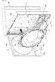
図4に示すように、パチンコ遊技機1は、縦長の方形枠状に形成され、遊技場に設置される遊技機設置島(図示略)に固定される外枠100と、外枠100の内側に開閉可能に取り付けられ、遊技盤6を含む遊技盤ユニット400が前面側から取り付けられる合成樹脂製の遊技枠110と、遊技枠110の前面側に開閉可能に設けられる額縁状に形成され、透視窓2aを有するガラス扉枠2と、遊技枠110の前面におけるガラス扉枠2の下方を開閉可能な下扉枠103と、から主に構成される。
As shown in FIG. 4, the pachinko gaming machine 1 is formed in a vertically long rectangular frame shape, and is fixed to a gaming machine installation island (not shown) installed in the game hall, and the inner side of the outer frame 100 The game board unit 400 including the game board 6 that can be opened and closed is attached to the front of the synthetic resin game frame 110, and the frame is provided on the front side of the game frame 110 so as to be opened and closed. It is mainly composed of a glass door frame 2 having a window 2a and a lower door frame 103 capable of opening and closing the lower side of the glass door frame 2 on the front surface of the game frame 110.
(遊技盤ユニット)
図4に示すように、遊技枠110の前面上部には、遊技盤ユニット400が取り付けられる取付部111が形成されており、該取付部111には、遊技盤ユニット400における後述するカバー体302(図5参照)の後部が嵌合される開口部112が形成されている。遊技盤ユニット400は、遊技盤ユニット400と遊技枠110との間に設けられる図示しない係止手段等を介して、遊技枠110に対して前面側から着脱自在に取り付けできるようになっている。
(Game board unit)
As shown in FIG. 4, an attachment portion 111 to which the game board unit 400 is attached is formed on the upper front portion of the game frame 110, and a cover body 302 (to be described later) in the game board unit 400 is formed on the attachment portion 111. An opening 112 is formed in which a rear portion is fitted (see FIG. 5). The game board unit 400 can be detachably attached to the game frame 110 from the front side via a locking means (not shown) provided between the game board unit 400 and the game frame 110.
遊技枠110における開口部112の下方には、打球操作ハンドル5の上部に設けられる図示しない打球発射装置にて発射される遊技球を、遊技盤6に向けて誘導する発射球誘導レール401cが配設されている。打球発射装置は、特に詳細な図示はしないが、発射球誘導レール401cの右側の下端部に設けられる打球発射位置に配置された遊技球を遊技盤6に向けて打ち出す打球部材(ハンマー等)と、該打球部材を揺動させるための電気的駆動源(モータ等)と、を一体的にユニット化したもの等で構成されている。また、発射球誘導レール401cは、帯状の金属板からなり、遊技枠110の前面110aに対して、該前面110a側の縁辺部Hを当接させた状態で取り付けられている。
Below the opening 112 in the game frame 110, there is arranged a launch ball guide rail 401c for guiding a game ball launched by a hitting ball launching device (not shown) provided on the top of the hitting operation handle 5 toward the game board 6. It is installed. Although not shown in detail, the hitting ball launching device is a hitting member (such as a hammer) for hitting a game ball arranged at the hitting ball launching position provided at the lower right end of the shot ball guiding rail 401c toward the game board 6. An electric drive source (motor or the like) for swinging the hitting ball member is integrally formed into a unit. The launch ball guide rail 401c is made of a belt-shaped metal plate and is attached to the front surface 110a of the game frame 110 with the edge H on the front surface 110a side in contact therewith.
発射球誘導レール401cは、ガラス扉枠2を閉鎖しても透視窓2aを通して視認できない位置に配置されており、ガラス扉枠2の下方に設けられた開閉扉により前面が被覆されるため、使用状態において遊技者側から視認されることはない。よって、遊技球が発射球誘導レール401cに沿って誘導され、それにより生じる振動により発射球誘導レール401cの前面110a側の縁辺部Hと前面110aとが擦れて削られた粉が前面に付着しても目立たないので、発射球誘導レール401cの前面110a側の縁辺部Hを前面110aに当接させて強固に取り付けている。
The firing ball guide rail 401c is disposed at a position where it cannot be seen through the transparent window 2a even when the glass door frame 2 is closed, and the front surface is covered by an open / close door provided below the glass door frame 2, In the state, it is not visually recognized from the player side. Therefore, the game ball is guided along the launch ball guide rail 401c, and the powder generated by rubbing the edge portion H on the front surface 110a side of the launch ball guide rail 401c and the front surface 110a by the vibration generated thereby adheres to the front surface. However, since it is not conspicuous, the edge H on the front surface 110a side of the firing ball guiding rail 401c is firmly attached to the front surface 110a.
図5に示すように、遊技盤ユニット400は、遊技盤6と、該遊技盤6の背面側に配置され、遊技盤6を背面側から装飾する装飾体301と、該装飾体301を遊技盤6に対して取り付けるためのカバー体302と、装飾体301の背面に取り付けられ、演出表示装置9及び演出制御基板80等を含む変動表示ユニット49と、から主に構成されている。
As shown in FIG. 5, the game board unit 400 is arranged on the back side of the game board 6, the game board 6 and decorates the game board 6 from the back side, and the decoration body 301 is attached to the game board. 6, and a variable display unit 49 that is attached to the back surface of the decorative body 301 and includes the effect display device 9, the effect control board 80, and the like.
装飾体301は、後述するように透明に形成される遊技盤6の遊技領域7を背面側から装飾する立体状に形成された装飾体であり、前後方向に所定幅の肉厚を有している。装飾体301の前面は、特に詳細な図示はしないが、非平坦面状に形成され、奥行き感のある装飾部が形成されている。また、遊技盤6側に設けられる各種表示装置(例えば第1特別図柄表示器8a、第2特別図柄表示器8b等)、駆動手段(ソレノイド16,21等)、LED、各種スイッチ(例えばゲートスイッチ32a、第1始動口スイッチ13a、第2始動口スイッチ13b、カウントスイッチ23等)から延出される配線は、遊技盤6の背面と装飾体301の前面との間から側方に引き出されるため、これら配線は、装飾部と同色または同系色に着色され、これにより配線が目立たないようにしている。
The decorative body 301 is a three-dimensional decorative body that decorates the game area 7 of the game board 6 formed transparently from the back side as will be described later, and has a thickness of a predetermined width in the front-rear direction. Yes. Although the front surface of the decorative body 301 is not particularly shown in detail, it is formed in a non-flat surface shape, and a decorative portion with a sense of depth is formed. Also, various display devices (for example, the first special symbol display 8a, the second special symbol display 8b, etc.) provided on the game board 6 side, driving means (solenoids 16, 21, etc.), LEDs, various switches (for example, gate switches) 32a, the first start port switch 13a, the second start port switch 13b, the count switch 23, etc.), because the wiring is drawn to the side from between the back surface of the game board 6 and the front surface of the decorative body 301, These wirings are colored in the same color or similar color as the decorative portion, thereby preventing the wirings from being noticeable.
また、装飾体301の略中央位置には、背面側に配設される演出表示装置9の表示画面9aを視認可能とするための開口部303が形成されているとともに、その周辺には、遊技領域7に配設される各種入賞口(例えば第1始動入賞口13や第2始動入賞口14等)に入賞した遊技球を背面側に排出するための遊技球排出口(図示略)が複数形成されている。さらに装飾体301には、特に図示はしないが、駆動手段等により可動自在に設けられる演出用の可動物や、LEDやランプ等の装飾用発光体が設けられる。このように構成された装飾体301は、背面側のカバー体302に前面側から組み付けられる。
In addition, an opening 303 for making the display screen 9a of the effect display device 9 arranged on the back side visible is formed at a substantially central position of the decorative body 301. There are a plurality of game ball discharge ports (not shown) for discharging game balls won in various winning ports (for example, the first start winning port 13 and the second start winning port 14) arranged in the area 7 to the back side. Is formed. Further, although not specifically shown, the decorative body 301 is provided with a movable object for presentation that is movably provided by a driving unit or the like, and a decorative light emitter such as an LED or a lamp. The decorative body 301 configured in this way is assembled to the cover body 302 on the back side from the front side.
尚、本実施例の装飾体301は、所定肉厚を有する一つの板状体にて構成されていたが、形状は種々に変形可能であるとともに、それぞれ個別に形成された複数の装飾体であってもよい。
Although the decorative body 301 of the present embodiment is configured by a single plate-shaped body having a predetermined thickness, the shape can be variously modified and a plurality of decorative bodies individually formed. There may be.
カバー体302は、透明な合成樹脂材からなり、前面が開口する箱状に形成された本体部311内に、装飾体301を前面側から収容可能に形成されている。本体部311の前面開口の周縁部からは、遊技盤6に取り付けるためのフランジ片310が外向きに形成されており、該フランジ片310の前面側には、遊技盤6に対する当該カバー体302の取付位置を決定するための複数の位置決め用ボス312a〜312d(図12参照)が前面側に向けて突設されているとともに、遊技盤6に当該カバー体302を取り付けるための取付ネジ313が取り付けられる取付穴314が複数箇所に形成されている。尚、図5中拡大図に示すように、これら位置決め用ボス312a〜312dのフランジ片310の前面からの高さ(突出長さ)寸法L4及び直径(外径)L5は全て同一とされている。
The cover body 302 is made of a transparent synthetic resin material, and is formed so that the decorative body 301 can be accommodated from the front side in a body portion 311 formed in a box shape having an open front surface. A flange piece 310 for attaching to the game board 6 is formed outward from the peripheral edge of the front opening of the main body 311, and the cover body 302 with respect to the game board 6 is provided on the front side of the flange piece 310. A plurality of positioning bosses 312a to 312d (see FIG. 12) for determining the mounting position are projected toward the front side, and mounting screws 313 for mounting the cover body 302 to the game board 6 are mounted. Mounting holes 314 are formed at a plurality of locations. As shown in the enlarged view of FIG. 5, the height (projection length) dimension L4 and the diameter (outer diameter) L5 of the positioning bosses 312a to 312d from the front surface of the flange piece 310 are all the same. .
本体部311の背板311aには、当該背板311aの背面側に組み付けられる演出表示装置9の表示画面9aを視認可能とするための開口部315が形成されている。演出表示装置9を含む変動表示ユニット49は、背板311aの背面側から演出表示装置9の表示画面9aを開口部315に臨ませるように背板311aの背面に取り付けられる。尚、変動表示ユニット49は、装飾体301の背面に直接取り付けてもよい。
An opening 315 is formed in the back plate 311 a of the main body 311 so that the display screen 9 a of the effect display device 9 assembled on the back side of the back plate 311 a can be seen. The variable display unit 49 including the effect display device 9 is attached to the back surface of the back plate 311a so that the display screen 9a of the effect display device 9 faces the opening 315 from the back side of the back plate 311a. Note that the variable display unit 49 may be directly attached to the back surface of the decorative body 301.
カバー体302には、これら装飾体301、変動表示ユニット49だけでなく、他の装置や基板等が組み付け可能とされており、カバー体302及び該カバー体302に一体的に組み付けられる装飾体301、変動表示ユニット49等を含む遊技に関連する複数の遊技用部品により、遊技用部品ユニット300が構成される。このように構成される遊技用部品ユニット300は、遊技盤6に対して着脱可能に取り付けられ、複数の機種に共通して使用される機種共通部品であるカバー体302に、機種固有の装飾体301や変動表示ユニット49等の各種遊技用部品を着脱可能に組み付けることができるため、遊技盤6の背面側に配設される複数の遊技用部品が組み付けられたカバー体302を遊技盤6の背面に取り付けるだけで、複数の遊技用部品を一度に配設することができるばかりか、機種変更やメンテナンスの際には、カバー体302から機種固有の装飾体や遊技用部品を取り外すことができるため、作業性が向上する。
In addition to the decorative body 301 and the variable display unit 49, other devices, boards, and the like can be assembled to the cover body 302. The cover body 302 and the decorative body 301 that is integrally assembled to the cover body 302. The gaming component unit 300 is composed of a plurality of gaming components related to the game including the variable display unit 49 and the like. The gaming component unit 300 configured as described above is detachably attached to the game board 6 and is attached to a cover 302, which is a model-common component used in common for a plurality of models, on a model-specific decorative body. Since various game parts such as 301 and the variable display unit 49 can be detachably assembled, a cover 302 assembled with a plurality of game parts arranged on the back side of the game board 6 is attached to the game board 6. It is possible not only to install a plurality of game parts at a time by simply attaching to the back side, but also to remove model-specific ornaments and game parts from the cover body 302 when changing models or performing maintenance. Therefore, workability is improved.
(遊技盤)
図6及び図7に示すように、遊技盤6は、アクリル樹脂、ポリカーボネート樹脂、メタクリル樹脂等の透明な合成樹脂材にて形成される盤面板200と、該盤面板200の背面200b側に一体的に取り付けられるスペーサ部材250と、から主に構成される。盤面板200の厚み幅寸法は約1cm程度であり、全体が透明に形成されている。尚、本実施例では盤面板200全体が透明に形成されているが、当該盤面板200の前面側からその背面側に配設される装飾体301を透視可能な透光性を有していれば、半透明であってもよいし、着色されていてもよい。また、全体が透光性を有していなくても、少なくとも遊技領域7の一部に透光部が形成されていればよい。
(Game board)
As shown in FIGS. 6 and 7, the game board 6 is integrated with a board surface plate 200 formed of a transparent synthetic resin material such as acrylic resin, polycarbonate resin, and methacrylic resin, and the back surface 200b side of the board surface board 200. The spacer member 250 is attached mainly. The thickness width dimension of the board surface plate 200 is about 1 cm, and the whole is formed to be transparent. In the present embodiment, the entire board plate 200 is formed transparent, but the board board 200 has a light-transmitting property capable of seeing through the decorative body 301 disposed on the back side from the front side of the board plate 200. For example, it may be translucent or colored. Moreover, even if the whole does not have translucency, the translucent part should just be formed in at least one part of the game area 7. FIG.
盤面板200には、背面側に配設される演出表示装置9の表示画面9aを前面側に臨ませるとともに、センター枠飾り11(図1参照)が取り付けられる取付穴201と、可変入賞球装置15(図1参照)が取り付けられる取付穴202と、特別可変入賞球装置20(図1参照)が取り付けられる取付穴203と、アウト口26(図1参照)を形成するアウト口穴204と、ゲート32(図1参照)が取り付けられる取付穴205と、装飾LED25aを有する装飾部材25L(図1参照)が取り付けられる取付穴206aと、装飾LED25bを有する装飾部材25R(図1参照)が取り付けられる取付穴206bと、がそれぞれ前後方向に貫通して形成されている。
The board surface plate 200 has a display screen 9a of the effect display device 9 disposed on the back side facing the front side, a mounting hole 201 to which the center frame decoration 11 (see FIG. 1) is attached, and a variable winning ball apparatus. 15 (see FIG. 1), a mounting hole 202 to which the special variable winning ball apparatus 20 (see FIG. 1) is attached, an out port hole 204 that forms the out port 26 (see FIG. 1), An attachment hole 205 to which the gate 32 (see FIG. 1) is attached, an attachment hole 206a to which the decoration member 25L (see FIG. 1) having the decoration LED 25a is attached, and a decoration member 25R (see FIG. 1) having the decoration LED 25b are attached. The mounting holes 206b are formed so as to penetrate in the front-rear direction.
各穴201〜206の周囲前面には、各部材を取り付けるためのネジが螺入されるネジ穴TAが複数箇所に形成されているとともに、外レール401aや内レール401b(図4参照)が取り付けられる取付穴TBが複数箇所に形成されている。
Screw holes TA into which screws for attaching each member are screwed are formed at a plurality of locations on the front surface around each of the holes 201 to 206, and the outer rail 401a and the inner rail 401b (see FIG. 4) are attached. Mounting holes TB are formed at a plurality of locations.
また、盤面板200の周囲には、スペーサ部材250から前面側に突設され、外レール飾り350a〜350c(図5参照)を取り付けるための取付ネジが取り付けられるネジ穴が先端に形成された複数の取付用ボス260a〜260h及びスペーサ部材250から前面側に突設され、証紙貼付部材352 (図5参照)を取り付けるための取付ネジが取り付けられるネジ穴が先端に形成された取付用ボス260jがそれぞれ挿通される挿通孔207a〜207jが、それぞれ対応した位置に前後方向に貫通して形成されている。
A plurality of screw holes are formed around the board surface plate 200 so as to protrude from the spacer member 250 to the front side and to which attachment screws for attaching the outer rail decorations 350a to 350c (see FIG. 5) are attached. There are mounting bosses 260j that protrude from the front side from the mounting bosses 260a to 260h and the spacer member 250 and have screw holes for mounting mounting screws for attaching the certificate sticking member 352 (see FIG. 5) formed at the tip. Insertion holes 207a to 207j that are respectively inserted are formed through the corresponding positions in the front-rear direction.
また、盤面板200を前面側から見たときにおける左上部、左下部、右上部には、スペーサ部材250から前面側に突設される複数の位置決め用ボス261a〜261cがそれぞれ嵌合される位置決め穴208a〜208cが、それぞれ対応した位置に前後方向に貫通して形成されている。尚、これら以外にも、複数の挿通孔や取付穴等が形成されている。
In addition, a plurality of positioning bosses 261a to 261c that protrude from the spacer member 250 to the front side are respectively fitted to the upper left, lower left, and upper right when the panel board 200 is viewed from the front side. Holes 208a to 208c are formed penetrating in the front-rear direction at corresponding positions. In addition to these, a plurality of insertion holes, mounting holes, and the like are formed.
また、盤面板200の側面における四隅近傍位置には、スペーサ部材250に形成された弾性係止爪270a〜270dがそれぞれ係止される係止段部220a〜220dがそれぞれ形成されている。係止段部220a〜220dは、盤面板200の側面における前面側の縁辺部に切欠形成される。
Further, locking step portions 220a to 220d to which the elastic locking claws 270a to 270d formed on the spacer member 250 are respectively locked are formed at positions near the four corners on the side surface of the board surface plate 200. The locking step portions 220 a to 220 d are notched in the front edge portion of the side surface of the board plate 200.
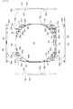
スペーサ部材250は、外形が盤面板200と同形に形成された板状部材の中央に、盤面板200の前面に略円形に形成される遊技領域7とほぼ同形の開口部251が形成されることにより枠状に形成されている。
The spacer member 250 has an opening 251 that is substantially the same shape as the game area 7 that is formed in a substantially circular shape on the front surface of the board plate 200 at the center of the plate-like member whose outer shape is formed in the same shape as the board board 200. Is formed in a frame shape.
詳しくは、図6〜図9に示すように、スペーサ部材250は、背板252と、該背板252の周縁から前面側に向けて立設された側壁253と、背板252の開口部251の周縁から前面側に向けて立設される円形状リブ254と、背板252の前面側における該円形状リブ254と側壁253とに囲まれた領域に格子状に立設されるリブ255と、により構成されている。円形状リブ254及びリブ255の高さ幅寸法(前後幅寸法)は約1cmで、側壁253の高さ幅寸法(前後幅寸法、約2cm)の約半分とされており、これら円形状リブ254及びリブ255の前端面にて構成される前面250a上に、盤面板200がその背面200bを当接するように組み付けられる。そして組み付けられた盤面板200の側周面の外側に側壁253が配置されて該側壁253により被覆され、接触や落下による損傷から保護されるようになっている。
Specifically, as shown in FIGS. 6 to 9, the spacer member 250 includes a back plate 252, a side wall 253 erected from the periphery of the back plate 252 toward the front surface, and an opening 251 of the back plate 252. A circular rib 254 erected from the peripheral edge toward the front surface side, and a rib 255 erected in a grid pattern in a region surrounded by the circular rib 254 and the side wall 253 on the front surface side of the back plate 252 , Is configured. The height width dimension (front-rear width dimension) of the circular rib 254 and the rib 255 is about 1 cm, which is about half of the height width dimension (front-rear width dimension, about 2 cm) of the side wall 253. These circular ribs 254 And the board surface board 200 is assembled | attached so that the back surface 200b may contact | abut on the front surface 250a comprised by the front end surface of the rib 255. FIG. And the side wall 253 is arrange | positioned on the outer side of the side peripheral surface of the assembled board surface board 200, and it covers with this side wall 253, and is protected from the damage by contact or a fall.
つまり、スペーサ部材250は、厚み幅寸法は約1cmであり、円形状リブ254及びリブ255の前端面にて構成される前面250aにより盤面板200の取付面が構成されており、該前面250aに配置される盤面板200とによって厚み幅寸法が約2cmの遊技盤6が構成される。
That is, the spacer member 250 has a thickness width dimension of about 1 cm, and the mounting surface of the board plate 200 is configured by the front surface 250a formed by the circular ribs 254 and the front end surfaces of the ribs 255. A game board 6 having a thickness width dimension of about 2 cm is constituted by the board surface plate 200 arranged.
側壁253の四隅近傍には、盤面板200の側周面に形成された係止段部220a〜220dに弾性的に係止される弾性係止爪270a〜270dが、前端部から切り溝を切り込むことにより形成されている。
In the vicinity of the four corners of the side wall 253, elastic locking claws 270a to 270d elastically locked to locking step portions 220a to 220d formed on the side peripheral surface of the board surface plate 200 cut the kerf from the front end portion. It is formed by.
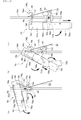
図7及び図8に示すように、背板252の前面側には、前述した取付用ボス260a〜260h,260jと、位置決め用ボス261a〜261cとが、それぞれリブ255の交差位から前面側に向けて突設されている。これら取付用ボス260a〜260h,260j及び位置決め用ボス261a〜261cは、側壁253の前端部より若干前面側に突出する長さを有している。そして特に取付用ボス260c、260fに関しては、他の取付用ボス260a,260b、260d〜260h,260j及び位置決め用ボス261a〜261cよりも若干長めに形成されており、後述するように組み付けられた盤面板200の遊技盤面200aよりも前面側に突出するようになっているとともに、ネジ穴260kが上下方向に貫通して形成されている。
As shown in FIGS. 7 and 8, the mounting bosses 260 a to 260 h and 260 j and the positioning bosses 261 a to 261 c described above are provided on the front side of the back plate 252 from the intersecting position of the rib 255 to the front side. Projected toward. The mounting bosses 260a to 260h and 260j and the positioning bosses 261a to 261c have a length that slightly protrudes from the front end of the side wall 253 to the front side. Particularly, the mounting bosses 260c and 260f are formed slightly longer than the other mounting bosses 260a, 260b, 260d to 260h, and 260j and the positioning bosses 261a to 261c, and are assembled as described later. The face plate 200 protrudes to the front side from the game board surface 200a, and a screw hole 260k is formed penetrating in the vertical direction.
このように構成されたスペーサ部材250の前面250aに盤面板200を配置すると、盤面板200に形成された各位置決め穴208a〜208c内に位置決め用ボス261a〜261cが背面側から嵌合され、スペーサ部材250に対する盤面板200の組み付け位置が決定されるとともに、各挿通孔207a〜207h,207j内に取付用ボス260a〜260h,260jがそれぞれ挿通され、各挿通孔207a〜207h,207jの先端に形成されたネジ穴が、盤面板200の遊技盤面200a側に臨むことになる。
When the board surface plate 200 is arranged on the front surface 250a of the spacer member 250 configured as described above, the positioning bosses 261a to 261c are fitted into the positioning holes 208a to 208c formed in the board surface plate 200 from the back side, and the spacer Assembling positions of the panel board 200 with respect to the member 250 are determined, and mounting bosses 260a to 260h and 260j are inserted into the insertion holes 207a to 207h and 207j, respectively, and formed at the tips of the insertion holes 207a to 207h and 207j. The screw hole thus made faces the game board surface 200a side of the board board 200.
また、盤面板200の背面200bがスペーサ部材250の前面250aに当接されると、各弾性係止爪270a〜270dが各係止段部220a〜220dに弾性的に係止され、スペーサ部材250からの盤面板200の離脱が規制される。このように各弾性係止爪270a〜270dが各係止段部220a〜220dに弾性的に係止された状態において、各弾性係止爪270a〜270dの先端は、盤面板200の遊技盤面200aよりも前面側に突出しないようになっている。
Further, when the back surface 200b of the board surface plate 200 is brought into contact with the front surface 250a of the spacer member 250, the elastic locking claws 270a to 270d are elastically locked to the locking step portions 220a to 220d, and the spacer member 250. The detachment of the board plate 200 from the board is regulated. Thus, in a state where the elastic locking claws 270a to 270d are elastically locked to the locking step portions 220a to 220d, the tips of the elastic locking claws 270a to 270d are the game board surface 200a of the board plate 200. It is designed not to protrude to the front side.
このように各弾性係止爪270a〜270dを含む側壁253の前端部は、組み付けられた盤面板200の遊技盤面200aよりも前面側に突出しない長さに形成されているため、盤面板200の遊技盤面200aよりも前面側に突出して、後述する製造時や保管、搬送時等において各弾性係止爪270a〜270dが床面や他の遊技盤6等と接触して破損することが防止される。
As described above, the front end portion of the side wall 253 including the elastic locking claws 270a to 270d is formed so as not to protrude to the front side from the game board surface 200a of the assembled board board 200. Projecting to the front side of the game board surface 200a, the elastic locking claws 270a to 270d are prevented from being damaged due to contact with the floor surface or other game boards 6 or the like during manufacturing, storage, or transportation described later. The
また、前面250aに盤面板200を配置することにより弾性係止爪270aが係止段部220aに係止されて盤面板200の前面250aからの離脱が防止されるため、盤面板200を前面250aに簡単に取り付けることができる。また、弾性係止爪270aは遊技盤面200aに形成される遊技領域7に影響が及ばない盤面板200の側面に係止されるばかりか、係止状態において弾性係止爪270aの先端が遊技盤面200aから突出することがないので、複数の遊技盤6を積み重ねたときに弾性係止爪270aの先端が上方の遊技盤6に接触して破損することが防止される。
Further, by disposing the board surface plate 200 on the front surface 250a, the elastic locking claw 270a is locked to the locking step portion 220a and the separation of the board surface plate 200 from the front surface 250a is prevented. Easy to install. Further, the elastic latching claw 270a is not only latched on the side surface of the board surface plate 200 which does not affect the game area 7 formed on the game board surface 200a, but the tip of the elastic latching claw 270a is in the game board surface in the latched state. Since it does not protrude from 200a, when the plurality of game boards 6 are stacked, it is prevented that the tips of the elastic locking claws 270a come into contact with the upper game board 6 and are damaged.
また、各位置決め穴208a〜208c内に嵌合された位置決め用ボス261a〜261c及び各挿通孔207a〜207h,207j内に挿通された取付用ボス260a,260b、260d〜260h,260jは、盤面板200の遊技盤面200aよりも前面側に突出しないが、取付用ボス260c、260fに関しては、盤面板200の遊技盤面200aよりも約5mmほど前面側に突出する(図8参照)。
The positioning bosses 261a to 261c fitted in the positioning holes 208a to 208c and the mounting bosses 260a, 260b, 260d to 260h, 260j inserted into the insertion holes 207a to 207h, 207j Although it does not protrude to the front side from the game board surface 200a of 200, the mounting bosses 260c and 260f protrude to the front side by about 5 mm from the game board surface 200a of the board plate 200 (see FIG. 8).
具体的には、スペーサ部材250の前面250aに突設された取付用ボス260c、260fの長さ寸法は、盤面板200の厚み幅寸法よりも長寸であり、また、盤面板200の遊技盤面200aからの突出長さ寸法は、嵌合凹部264c、264fの深さ寸法よりも長寸とされている。
Specifically, the length dimension of the mounting bosses 260c and 260f projecting from the front surface 250a of the spacer member 250 is longer than the thickness width dimension of the board surface plate 200, and the game board surface of the board surface plate 200 The protruding length from 200a is longer than the depth of fitting recesses 264c and 264f.
図9に示すように、背板252における開口部251の下部には、アウト口穴204に連通するアウト開口部262が形成されている。背板252の前面側におけるアウト開口部262の周縁にもアウト口リブ263(図6、図7参照)が立設され、その前端面が盤面板200の背面200b200bにおけるアウト口穴204の周縁に当接するようになっており、これにより前後方向に所定幅寸法を有するアウト開口部262を構成している。
As shown in FIG. 9, an out opening 262 communicating with the out port hole 204 is formed in the lower portion of the opening 251 in the back plate 252. Out-out ribs 263 (see FIGS. 6 and 7) are also erected on the periphery of the out-opening 262 on the front side of the back plate 252, and the front end surface thereof is on the periphery of the out-opening hole 204 in the back surface 200 b 200 b of the panel board 200. Thus, an out opening 262 having a predetermined width dimension in the front-rear direction is configured.
背板252の背面250bにおける取付用ボス260c、260fに対応する箇所には、該取付用ボス260c、260fの先端がそれぞれ嵌合可能な内径(大きさ)を有する円形状の嵌合凹部264c、264fが凹設されており、特に図示はしないが、複数の遊技盤6を上下方向に積み重ねたときに、下方の遊技盤6の取付用ボス260c、260fが嵌合凹部264c、264fに嵌合されるようになっている。つまり、嵌合凹部264c、264fの内径は、取付用ボス260c、260fの外径よりも大寸に形成されている。
Circular fitting recesses 264c having inner diameters (sizes) into which the tips of the mounting bosses 260c and 260f can be fitted, respectively, at positions corresponding to the mounting bosses 260c and 260f on the back surface 250b of the back plate 252. 264f is recessed, and although not particularly shown, when a plurality of game boards 6 are stacked in the vertical direction, the mounting bosses 260c and 260f of the lower game board 6 are fitted into the fitting recesses 264c and 264f. It has come to be. That is, the inner diameters of the fitting recesses 264c and 264f are formed larger than the outer diameters of the mounting bosses 260c and 260f.
背板252における開口部251の上部左右側及び下部左右側には、前述したカバー体302に設けられた位置決め用ボス312a〜312dが嵌合可能な円形状のカバー体用位置決め穴265a〜265dが形成されている。詳しくは、背板252における位置決め用ボス312aに対応する位置にカバー体用位置決め穴265aが設けられ、位置決め用ボス312bに対応する位置にカバー体用位置決め穴265bが設けられ、位置決め用ボス312cに対応する位置にカバー体用位置決め穴265cが設けられ、位置決め用ボス312dに対応する位置にカバー体用位置決め穴265dが設けられている。
Circular cover body positioning holes 265a to 265d into which the positioning bosses 312a to 312d provided on the cover body 302 can be fitted are formed on the upper left and right sides and the lower left and right sides of the opening 251 in the back plate 252. Is formed. Specifically, a cover body positioning hole 265a is provided at a position corresponding to the positioning boss 312a on the back plate 252, and a cover body positioning hole 265b is provided at a position corresponding to the positioning boss 312b. A cover body positioning hole 265c is provided at a corresponding position, and a cover body positioning hole 265d is provided at a position corresponding to the positioning boss 312d.
これらカバー体用位置決め穴265a〜265dのうち、背面側から見て右上及び右下のカバー体用位置決め穴265a,265dの内径L1は、背面側から見て左上及び左下のカバー体用位置決め穴265b,265cの内径L2よりも大径とされているとともに(L1>L2)、上下の側壁253寄りに配置されている。
Of these cover body positioning holes 265a to 265d, the inner diameters L1 of the upper right and lower right cover body positioning holes 265a and 265d when viewed from the back side are the upper left and lower left cover body positioning holes 265b when viewed from the back side. , 265c is larger than the inner diameter L2 (L1> L2), and is disposed closer to the upper and lower side walls 253.
また、各カバー体用位置決め穴265a〜265dからは、開口部251の周縁まで延びる案内凹溝266a〜266d(図9、図10参照)が上下方向に向けて凹設されている。これら案内凹溝266a〜266dは、カバー体用位置決め穴265a〜265dから開口部251の周縁に向けて漸次幅広となるように形成されており、案内凹溝266a〜266dにおける幅広部に位置決め用ボス312a〜312dの先端を載置した後、カバー体用位置決め穴265a〜265dに向けて位置決め用ボス312a〜312dの先端を滑らせることで、カバー体用位置決め穴265a〜265dに容易に嵌合できるようになっている。
Further, from each of the cover body positioning holes 265a to 265d, guide concave grooves 266a to 266d (see FIGS. 9 and 10) extending to the periphery of the opening 251 are recessed in the vertical direction. These guide grooves 266a to 266d are formed so as to gradually widen from the cover body positioning holes 265a to 265d toward the periphery of the opening 251, and the positioning bosses are formed at the wide portions of the guide grooves 266a to 266d. After the tips of 312a to 312d are placed, the tips of the positioning bosses 312a to 312d are slid toward the cover body positioning holes 265a to 265d, so that they can be easily fitted into the cover body positioning holes 265a to 265d. It is like that.
また、背板252の背面250bにおける開口部251の周縁部には、各外レール飾り350a〜350cの前端面に遊技領域7の周縁に沿うように立設された円弧状のリブ351の先端が係合する円弧状の係合段部267が、開口部251の周縁部に沿って延設されている。尚、係合段部267は、スペーサ部材250の背面250bにおける開口部251の周縁に沿うように背面視C字形状に形成される当接面267aと、該当接面267aの外周縁に垂設される規制面267bと、から構成されている(図11参照)。
Further, at the peripheral edge of the opening 251 on the back surface 250b of the back plate 252, the tip of an arc-shaped rib 351 erected on the front end surface of each outer rail decoration 350a to 350c so as to follow the peripheral edge of the game area 7 is provided. An arcuate engaging step 267 that engages is extended along the peripheral edge of the opening 251. The engagement step portion 267 is suspended from the contact surface 267a formed in a C shape in the back view along the periphery of the opening 251 on the back surface 250b of the spacer member 250 and the outer periphery of the contact surface 267a. The restriction surface 267b is configured (see FIG. 11).
各外レール飾り350a〜350cを盤面板200の遊技盤面200aに取り付けたときに、外レール飾り350a〜350cの前端面に立設された円弧状のリブ351の端部同士が接続されて、正面視環状のリブ351が形成される。よって、特に図示はしないが、複数の遊技盤6を積み重ねたときに、下方の遊技盤6のリブ351が上方の遊技盤6の係合段部267に嵌合され、該環状のリブ351の外周が規制面267bにより規制され、これにより下方の遊技盤6に対する上方の遊技盤6の滑落が防止される。
When each outer rail decoration 350a-350c is attached to the game board surface 200a of the board 200, the ends of the arc-shaped ribs 351 standing on the front end surfaces of the outer rail decorations 350a-350c are connected to each other. A ring-shaped rib 351 is formed. Therefore, although not particularly illustrated, when a plurality of game boards 6 are stacked, the ribs 351 of the lower game board 6 are fitted into the engagement step portions 267 of the upper game board 6, and the annular ribs 351 are formed. The outer periphery is regulated by the regulation surface 267b, and thus the upper game board 6 is prevented from sliding down with respect to the lower game board 6.
尚、係合段部267は、スペーサ部材250を背面側から見て開口部251の周縁における右側の一部がなく、背面視略C字形に形成されているが、環状に形成されていてもよい。さらに、必ずしも環状に形成されていなくてもよいが、少なくとも背面視C字形または開口部251の周縁における少なくとも3箇所に形成されていることが好ましく、このようにすれば、環状のリブ351の水平移動を規制できる。
The engagement step portion 267 does not have a part on the right side at the periphery of the opening 251 when the spacer member 250 is viewed from the back side, and is formed in a substantially C shape when viewed from the back side. Good. Furthermore, although it does not necessarily have to be formed in an annular shape, it is preferably formed in at least three places on the periphery of the C-shape or the opening 251 in the back view. Can restrict movement.
(遊技盤に対する部品ユニットの取り付け)
次に、遊技盤に対する部品ユニットの取り付けについて、図9〜図13にもとづいて説明する。図9は、遊技盤面に流下方向変更部材が取り付けられた遊技盤を示す背面図である。図10は、(a)は図9のS−S断面図であり、(b)は図9のT−T断面図である。図11は、案内凹溝を示す拡大斜視図である。図12は、遊技盤に部品ユニットを取り付ける状況を示す斜視図である。図13は、(a)はカバー体用位置決め穴の配置位置関係を示す概略図であり、(b)(c)はカバー体用位置決め穴の配置位置関係の変形例を示す概略図である。
(Attaching the component unit to the game board)
Next, attachment of the component unit to the game board will be described with reference to FIGS. FIG. 9 is a rear view showing the game board in which the flow direction changing member is attached to the game board surface. 10A is an SS cross-sectional view of FIG. 9, and FIG. 10B is a TT cross-sectional view of FIG. 9. FIG. 11 is an enlarged perspective view showing a guide groove. FIG. 12 is a perspective view showing a state in which the component unit is attached to the game board. FIGS. 13A and 13B are schematic views showing the arrangement positional relationship of the cover body positioning holes, and FIGS. 13B and 13C are schematic views showing a modification of the arrangement positional relationship of the cover body positioning holes.
図9及び図10に示すように、スペーサ部材250の背板252における開口部251の上部左右側及び下部左右側には、カバー体302に設けられた位置決め用ボス312a〜312dが嵌合可能な円形状のカバー体用位置決め穴265a〜265dが形成されている。尚、本実施例では、カバー体用位置決め穴265a〜265dと盤面板200の背面200bとにより、位置決め用ボス312a〜312dが嵌合可能な凹部が構成されているが、スペーサ部材250の背板252に直接凹部を形成してもよい。
As shown in FIGS. 9 and 10, positioning bosses 312 a to 312 d provided on the cover body 302 can be fitted to the upper left and right sides and the lower left and right sides of the opening 251 in the back plate 252 of the spacer member 250. Circular cover body positioning holes 265a to 265d are formed. In this embodiment, the cover body positioning holes 265a to 265d and the back surface 200b of the panel board 200 form recesses into which the positioning bosses 312a to 312d can be fitted. A recess may be formed directly on 252.
図13には、上側の左右のカバー体用位置決め穴265a,265bと位置決め用ボス312a,312bとの関係を示す概略図が示されている。背面側から見て、右側のカバー体用位置決め穴265aの内径(幅寸法)L1は、左側のカバー体用位置決め穴265bの内径L2よりも大径とされている(L1>L2)。位置決め用ボス312a,312bの外径L5は同一であるとともに、カバー体用位置決め穴265aの内径L1よりも小径(L5<L1)で、かつ、カバー体用位置決め穴265aの内径L2とほぼ同寸(L5≒L1)または外径L5は内径L2よりも僅かに小径とされている。つまり、カバー体用位置決め穴265a,265dの内径L1と位置決め用ボス312a、312dの外径L5との差寸法L14(L1−L5)が、カバー体用位置決め穴265b,265cの内径L2と位置決め用ボス312b、312cの外径L5との差寸法(L2−L5)よりも大きい(L1−L5>L2−L5)。
FIG. 13 is a schematic view showing the relationship between the upper left and right cover body positioning holes 265a and 265b and the positioning bosses 312a and 312b. When viewed from the back side, the inner diameter (width dimension) L1 of the right cover body positioning hole 265a is larger than the inner diameter L2 of the left cover body positioning hole 265b (L1> L2). The positioning bosses 312a and 312b have the same outer diameter L5, a smaller diameter (L5 <L1) than the inner diameter L1 of the cover body positioning hole 265a, and substantially the same size as the inner diameter L2 of the cover body positioning hole 265a. (L5≈L1) or the outer diameter L5 is slightly smaller than the inner diameter L2. That is, the difference dimension L14 (L1-L5) between the inner diameter L1 of the cover body positioning holes 265a and 265d and the outer diameter L5 of the positioning bosses 312a and 312d is equal to the inner diameter L2 of the cover body positioning holes 265b and 265c. It is larger than the difference dimension (L2−L5) from the outer diameter L5 of the bosses 312b and 312c (L1−L5> L2−L5).
また、第2凹部としての左側のカバー体用位置決め穴265bは、位置決めの際に基準となる右側の第1凹部としてのカバー体用位置決め穴265aに対して、第1凸部としての位置決め用ボス312aと第2凸部としての位置決め用ボス312bとの離間幅寸法L10から、カバー体用位置決め穴265aの内径(幅寸法)L1と位置決め用ボス312aの外径(幅寸法)との差寸法L14(=L1−L5)を減算した最少幅寸法L12(L10−L14)と離間幅寸法L10と同寸の最大幅寸法L13(=L10)との中間の離間幅寸法L11だけ離間して配置されている。
Further, the left cover body positioning hole 265b as the second recess has a positioning boss as the first protrusion with respect to the cover body positioning hole 265a as the right first recess serving as a reference in positioning. A difference dimension L14 between the inner diameter (width dimension) L1 of the positioning hole 265a for the cover body and the outer diameter (width dimension) of the positioning boss 312a from the separation width dimension L10 of the positioning boss 312b as the second convex portion 312a. (= L1-L5) is subtracted by a separation width dimension L11 which is intermediate between a minimum width dimension L12 (L10-L14) and a separation width dimension L10 and a maximum width dimension L13 (= L10) of the same dimension. Yes.
尚、下側の左右のカバー体用位置決め穴265c,265dと位置決め用ボス312c,312dとは、図13に示す上側の左右のカバー体用位置決め穴265a,265bと位置決め用ボス312a,312bとの関係と同様であるため、詳細な説明は省略する。
The lower left and right cover body positioning holes 265c and 265d and the positioning bosses 312c and 312d are the same as the upper left and right cover body positioning holes 265a and 265b and the positioning bosses 312a and 312b shown in FIG. Since it is the same as the relationship, detailed description is omitted.
図9及び図10に示すように、各カバー体用位置決め穴265a〜265dからは、開口部251の周縁まで延びる案内凹溝266a〜266d(図10、図11参照)が上下方向に向けて凹設されている。これら案内凹溝266a〜266dは、スペーサ部材250の背面250bに形成され、該カバー体用位置決め穴265a〜265dの面積よりも大きい案内領域を構成する底面G1と、底面G1の周囲を囲むように立設され、位置決め用ボス312a〜312dの高さ寸法よりも短寸の高さ寸法を有する壁部を構成する内側面G2と、から断面視凹状に構成されている。
As shown in FIGS. 9 and 10, guide concave grooves 266 a to 266 d (see FIGS. 10 and 11) extending to the periphery of the opening 251 are recessed from the cover body positioning holes 265 a to 265 d in the vertical direction. It is installed. These guide grooves 266a to 266d are formed on the back surface 250b of the spacer member 250, and surround the bottom surface G1 that forms a guide region larger than the area of the cover body positioning holes 265a to 265d and the periphery of the bottom surface G1. The inner side surface G2 that constitutes a wall portion that is erected and has a height dimension shorter than the height dimension of the positioning bosses 312a to 312d is configured to be concave in a sectional view.
具体的には、前記案内領域とは、底面G1及び各カバー体用位置決め穴265a〜265dの開口領域とを含む大きさの領域であり、該案内領域の端部にカバー体用位置決め穴265a〜265dが形成されていることになる。つまり、背面250bにおける帯状の案内領域に案内凹溝266a〜266dが形成され、該案内凹溝266a〜266dの底面領域の一部にカバー体用位置決め穴265a〜265dが形成される(底面G1は該案内領域からカバー体用位置決め穴265a〜265dを除く領域を構成している)。また、案内凹溝266a〜266dの深さ寸法、つまり、内側面G2の高さ寸法L3(底面G1から背面250bまでの幅寸法)は、位置決め用ボス312a〜312dの高さ寸法L4よりも小寸とされている(L3<L4)ことで、位置決め用ボス312a〜312dがカバー体用位置決め穴265a〜265d内に挿入されるようになっている。
Specifically, the guide region is a region having a size including the bottom surface G1 and the opening regions of the cover body positioning holes 265a to 265d, and the cover body positioning holes 265a to 265a are formed at the ends of the guide regions. 265d is formed. That is, the guide grooves 266a to 266d are formed in the belt-shaped guide region on the back surface 250b, and the cover body positioning holes 265a to 265d are formed in a part of the bottom region of the guide grooves 266a to 266d (the bottom surface G1 is A region excluding the cover body positioning holes 265a to 265d is formed from the guide region). Further, the depth dimension of the guide grooves 266a to 266d, that is, the height dimension L3 of the inner side surface G2 (the width dimension from the bottom surface G1 to the rear surface 250b) is smaller than the height dimension L4 of the positioning bosses 312a to 312d. With the dimensions (L3 <L4), the positioning bosses 312a to 312d are inserted into the cover body positioning holes 265a to 265d.
そして案内凹溝266a〜266dの底面G1は、カバー体用位置決め穴265a〜265dから開口部251の周縁に向けて、つまり遠ざかるにつれて幅寸法が漸次幅広となるように形成されている。よって、案内凹溝266a〜266dにおける幅広部に位置決め用ボス312a〜312dの先端を載置した後、カバー体用位置決め穴265a〜265dに向けて位置決め用ボス312a〜312dの先端を滑らせることで、カバー体用位置決め穴265a〜265dに容易に嵌合できるようになっている。
The bottom surfaces G1 of the guide grooves 266a to 266d are formed so that the width dimension gradually becomes wider from the cover body positioning holes 265a to 265d toward the peripheral edge of the opening 251, that is, as the distance is increased. Accordingly, after the tips of the positioning bosses 312a to 312d are placed on the wide portions of the guide grooves 266a to 266d, the tips of the positioning bosses 312a to 312d are slid toward the cover body positioning holes 265a to 265d. The cover body positioning holes 265a to 265d can be easily fitted.
このように構成されたスペーサ部材250の背面250bに、遊技用部品ユニット300を取り付ける場合、図12に示すように、例えば遊技盤6を背面を上方に向けた状態で載置面上に載置し、遊技用部品ユニット300を、その前面側から組み付けられた装飾体301を遊技盤6に対向させた状態で上方から取り付ける。
When the gaming component unit 300 is attached to the back surface 250b of the spacer member 250 configured in this way, as shown in FIG. 12, for example, the game board 6 is placed on the placement surface with the back surface facing upward. Then, the gaming component unit 300 is attached from above with the decorative body 301 assembled from the front side facing the gaming board 6.
この場合、例えば、複数のカバー体用位置決め穴265a〜265dのうち、上側のカバー体用位置決め穴265a、265bまたは下側のカバー体用位置決め穴265c、265dのいずれかから位置決めを行うかを決定し、上側または下側のうち大径のカバー体用位置決め穴265a、265dから位置決め用ボス312a、312dを嵌合させることが好ましい。
In this case, for example, it is determined whether to perform positioning from the upper cover body positioning holes 265a and 265b or the lower cover body positioning holes 265c and 265d among the plurality of cover body positioning holes 265a to 265d. The positioning bosses 312a and 312d are preferably fitted from the large-diameter cover body positioning holes 265a and 265d on the upper side or the lower side.
次に、上側のカバー体用位置決め穴265aを足がかりとして位置決めを行う場合の具体例を説明する。
Next, a specific example in the case of positioning using the upper cover body positioning hole 265a as a foothold will be described.
まず、図12に示すように、例えば遊技盤6を背面を上向きにした状態で所定の設置面に設置した後、遊技用部品ユニット300を持ち上げ、前面側の位置決め用ボス312a〜312dを遊技盤6に対向させるように遊技盤6の上方に配置する。
First, as shown in FIG. 12, for example, after the game board 6 is installed on a predetermined installation surface with the back face up, the game component unit 300 is lifted, and the positioning bosses 312a-312d on the front side are moved to the game board. The game board 6 is disposed above the game board 6 so as to face the board 6.
そして、位置決め用ボス312aが、カバー体用位置決め穴265a及び該カバー体用位置決め穴265aから連設される案内凹溝266aの底面G1からなる案内領域上に載置されるように遊技用部品ユニット300の上部側を下方に傾倒させるように下降する。このとき、案内凹溝266aの底面G1は開口部251の周縁に向けて漸次幅広となるように開口部251に向けて延設されている、つまり底面G1はカバー体用位置決め穴265aの開口面積よりも面積が大きいため、カバー体用位置決め穴265aに直接挿入するよりも簡単に案内凹溝266a内に載置させることができる。
Then, the gaming component unit is arranged such that the positioning boss 312a is placed on the guide area formed by the cover body positioning hole 265a and the bottom surface G1 of the guide groove 266a provided continuously from the cover body positioning hole 265a. The upper side of 300 is lowered so as to tilt downward. At this time, the bottom surface G1 of the guide groove 266a is extended toward the opening 251 so as to gradually increase toward the periphery of the opening 251. That is, the bottom surface G1 is the opening area of the cover body positioning hole 265a. Since the area is larger than that, it can be placed in the guide groove 266a more easily than directly inserted into the cover positioning hole 265a.
次いで、案内凹溝266aの底面G1上に位置決め用ボス312aが載置された場合、遊技用部品ユニット300(カバー体302)の荷重を底面G1上に掛けた状態で、位置決め用ボス312aがカバー体用位置決め穴265aに向けて移動するように遊技用部品ユニット300を上方に向けてスライド移動させる(図11参照)。このとき、位置決め用ボス312aが案内凹溝266aの左右側に配置された内側面G2によりガイドされてカバー体用位置決め穴265aに向けて案内される。これにより、位置決め用ボス312aが底面G1上から逸脱することが防止されるとともに、カバー体用位置決め穴265aに近づくにつれて、カバー体用位置決め穴265aに対する位置決め用ボス312aの左右方向の位置ずれが漸次小さくなっていくため、遊技用部品ユニット300をスライドさせるだけで位置決め用ボス312aをカバー体用位置決め穴265a内に簡単に挿入することができる。
Next, when the positioning boss 312a is placed on the bottom surface G1 of the guide groove 266a, the positioning boss 312a covers the game component unit 300 (cover body 302) with the load applied on the bottom surface G1. The gaming component unit 300 is slid upwardly so as to move toward the body positioning hole 265a (see FIG. 11). At this time, the positioning boss 312a is guided toward the cover body positioning hole 265a by being guided by the inner surface G2 disposed on the left and right sides of the guide groove 266a. Accordingly, the positioning boss 312a is prevented from deviating from the bottom surface G1, and as the cover body positioning hole 265a is approached, the lateral displacement of the positioning boss 312a with respect to the cover body positioning hole 265a gradually increases. Therefore, the positioning boss 312a can be easily inserted into the cover body positioning hole 265a simply by sliding the gaming component unit 300.
そして、このように位置決め用ボス312aがカバー体用位置決め穴265a内に挿入された状態で、カバー体用位置決め穴265a内で位置決め用ボス312aを中心として遊技用部品ユニット300を遊技盤6の背面に対して水平回転させる。この際、位置決め用ボス312aがカバー体用位置決め穴265aの内周面により囲まれることで、回転中心が大きくずれることがないため、位置決め用ボス312bをカバー体用位置決め穴265bに簡単に合致させて嵌合することができる。尚、この場合も、一旦案内凹溝266bの底面G1上に位置決め用ボス312bを載置してから位置決め用ボス312bをカバー体用位置決め穴265bに向けてスライドさせて嵌合してもよい。
Then, with the positioning boss 312a inserted into the cover body positioning hole 265a in this way, the game component unit 300 is placed in the cover body positioning hole 265a around the positioning boss 312a as the back of the game board 6. Rotate horizontally with respect to. At this time, since the positioning boss 312a is surrounded by the inner peripheral surface of the cover body positioning hole 265a, the center of rotation is not greatly shifted. Therefore, the positioning boss 312b can be easily aligned with the cover body positioning hole 265b. Can be fitted. In this case, the positioning boss 312b may be once placed on the bottom surface G1 of the guide groove 266b, and then the positioning boss 312b may be slid toward the cover body positioning hole 265b to be fitted.
そして上側のカバー体用位置決め穴265a、265bに位置決め用ボス312a、312bを挿入した状態で、遊技用部品ユニット300の下部側を下方に傾倒させて下降させれば、カバー体用位置決め穴265c、265dに位置決め用ボス312c、312dが嵌合され、これにより遊技盤6に対する遊技用部品ユニット300の取付位置が決定される。このとき、背面側から見て左側の上下のカバー体用位置決め穴265b,265cに位置決め用ボス312b,312cが嵌合されるため、遊技盤6に対する遊技用部品ユニット300の水平方向の位置ずれが規制される。
Then, with the positioning bosses 312a and 312b inserted into the upper cover body positioning holes 265a and 265b, if the lower side of the gaming component unit 300 is tilted downward and lowered, the cover body positioning holes 265c and Positioning bosses 312c and 312d are fitted to 265d, whereby the mounting position of the game component unit 300 with respect to the game board 6 is determined. At this time, since the positioning bosses 312b and 312c are fitted in the upper and lower cover body positioning holes 265b and 265c on the left side when viewed from the back side, the horizontal displacement of the gaming component unit 300 with respect to the gaming board 6 is caused. Be regulated.
そして図12に示すように、遊技盤6の背面側に位置決めされた遊技用部品ユニット300は、各取付穴314に背面側から取付ネジ313を取り付け、スペーサ部材250の背板252に形成されたネジ穴に螺入することで、遊技盤6の背面における所定の取り付け位置に所定の姿勢で取り付けられる(止着される)。このように遊技用部品ユニット300がスペーサ部材250の背板252に止着されることで、遊技領域7が形成される盤面板200に遊技用部品ユニット300のネジ穴等を形成しなくて済むため、盤面板200の強度の低下が防止される。
Then, as shown in FIG. 12, the gaming component unit 300 positioned on the back side of the game board 6 is formed on the back plate 252 of the spacer member 250 by attaching a mounting screw 313 to each mounting hole 314 from the back side. By screwing into the screw holes, the game board 6 is attached (fixed) in a predetermined posture at a predetermined attachment position on the back surface of the game board 6. In this way, the gaming component unit 300 is fastened to the back plate 252 of the spacer member 250, so that it is not necessary to form a screw hole or the like of the gaming component unit 300 on the board 200 on which the gaming area 7 is formed. Therefore, a decrease in the strength of the board surface plate 200 is prevented.
以上説明したように、遊技盤6を背面側に向けた状態で設置し、その上方から遊技用部品ユニット300の位置決め用ボス312a〜312dをカバー体用位置決め穴265a〜265dに嵌合することで、遊技盤6に対する遊技用部品ユニット300の取り付け位置を簡単に決定することができるばかりか、位置決め用ボス312aをカバー体用位置決め穴265aに嵌合する際には、カバー体用位置決め穴265aから周辺に広がる底面G1上に載置した位置決め用ボス312aをカバー体用位置決め穴265aに向けてスライド移動させればよく、その際に内側面G2により位置決め用ボス312aが底面G1外に逸脱してカバー体用位置決め穴265aから離れることが防止されるため、遊技用部品ユニット300が大きい場合や重量がある場合でも、位置決め用ボス312aのカバー体用位置決め穴265aへの嵌合作業を極めて簡単に行うことができる。
As described above, the game board 6 is installed in a state facing the back side, and the positioning bosses 312a to 312d of the game component unit 300 are fitted into the cover body positioning holes 265a to 265d from above. In addition to being able to easily determine the mounting position of the game component unit 300 with respect to the game board 6, when the positioning boss 312a is fitted into the cover body positioning hole 265a, the cover body positioning hole 265a is used. The positioning boss 312a placed on the bottom surface G1 spreading around the periphery may be slid toward the cover body positioning hole 265a. At this time, the positioning boss 312a deviates from the bottom surface G1 by the inner surface G2. Since it is prevented from leaving the cover body positioning hole 265a, the game component unit 300 may be large or heavy. Even if there is, it is possible to perform a fitting operation of the cover body for positioning hole 265a of the positioning bosses 312a very easily.
また、カバー体用位置決め穴265aは、内側面G2に接する位置に形成され、該内側面G2は円形のカバー体用位置決め穴265aの接線方向に延設されている、つまり内側面G2はカバー体用位置決め穴265aから連設されているため、底面G1上に載置した位置決め用ボス312aを内側面G2に摺接させてスライド移動させることにより、該位置決め用ボス312aをカバー体用位置決め穴265aに確実に嵌合させることができる。
Further, the cover body positioning hole 265a is formed at a position in contact with the inner side surface G2, and the inner side surface G2 extends in the tangential direction of the circular cover body positioning hole 265a, that is, the inner side surface G2 is the cover body. Since the positioning boss 312a is continuously provided from the positioning surface 265a, the positioning boss 312a placed on the bottom surface G1 is slidably brought into sliding contact with the inner side surface G2 to thereby move the positioning boss 312a to the cover body positioning hole 265a. Can be reliably fitted.
尚、本実施例では、カバー体用位置決め穴265aは、帯状の案内領域の端部周縁に立設された内側面G2に接するように設けられていたが、例えばカバー体用位置決め穴265aよりも大きな案内領域上に、カバー体用位置決め穴265aが該案内領域の周縁に立設された内側面G2に接しない位置に設けられていてもよい。
In this embodiment, the cover body positioning hole 265a is provided so as to be in contact with the inner side surface G2 erected on the peripheral edge of the end of the belt-shaped guide region. For example, the cover body positioning hole 265a is more than the cover body positioning hole 265a. On the large guide region, the cover body positioning hole 265a may be provided at a position not in contact with the inner side surface G2 standing on the periphery of the guide region.
また、このようにカバー体用位置決め穴265aが、該カバー体用位置決め穴265aよりも大きな案内領域上に、カバー体用位置決め穴265aが該案内領域の周縁に接しない位置に設けられている場合において、該カバー体用位置決め穴265aと内側面G2との間の案内領域の幅寸法が位置決め用ボス312aの外径L5よりも短寸となる位置に形成されていれば、底面G1上に載置した位置決め用ボス312aを、カバー体用位置決め穴265aの反対側の内側面G2に当接させるように押し込めば、該位置決め用ボス312aの一部がカバー体用位置決め穴265aに確実に差し掛かかるので、簡単に嵌合させることができる。
Further, when the cover body positioning hole 265a is provided on the guide area larger than the cover body positioning hole 265a in such a position that the cover body positioning hole 265a is not in contact with the peripheral edge of the guide area. If the width dimension of the guide region between the cover body positioning hole 265a and the inner side surface G2 is formed at a position shorter than the outer diameter L5 of the positioning boss 312a, it is mounted on the bottom surface G1. If the placed positioning boss 312a is pushed into contact with the inner surface G2 on the opposite side of the cover body positioning hole 265a, a part of the positioning boss 312a is surely inserted into the cover body positioning hole 265a. Therefore, it can be easily fitted.
尚、本実施例では、カバー体用位置決め穴265aの周縁に立設されている内側面G2は案内領域の周縁上に立設されているため、底面G1上に載置した位置決め用ボス312aを、カバー体用位置決め穴265aの反対側の内側面G2に当接させるように押し込めば、該位置決め用ボス312aの一部がカバー体用位置決め穴265aに確実に差し掛かかるので、簡単に嵌合させることができる。
In the present embodiment, since the inner side surface G2 standing on the periphery of the cover body positioning hole 265a stands on the periphery of the guide region, the positioning boss 312a placed on the bottom surface G1 is provided. If it is pushed so as to contact the inner surface G2 on the opposite side of the cover body positioning hole 265a, a part of the positioning boss 312a is surely engaged with the cover body positioning hole 265a so that it can be easily fitted. Can be made.
また、本実施例では、底面G1は帯状に形成され、底面G1を挟んで互いに対向するように該底面G1の長手方向に延設される左右一対の壁面部を構成する内側面G2,G2を有していることで、底面G1上に載置した位置決め用ボス312aが左右一対の内側面G2,G2に挟まれた状態でカバー体用位置決め穴265aに向けて案内されるため、簡単に嵌合させることができる。
Further, in this embodiment, the bottom surface G1 is formed in a band shape, and the inner side surfaces G2 and G2 constituting a pair of left and right wall surfaces extending in the longitudinal direction of the bottom surface G1 so as to face each other with the bottom surface G1 interposed therebetween. The positioning boss 312a placed on the bottom surface G1 is guided toward the cover body positioning hole 265a while being sandwiched between the pair of left and right inner surfaces G2 and G2. Can be combined.
また、これら左右一対の内側面G2,G2は、カバー体用位置決め穴265aに向けて幅寸法が漸次短寸となるように配置されていることで、位置決め用ボス312aを底面G1上における幅広部に載置すれば、後はカバー体用位置決め穴265aに向けてスライドさせるだけで、カバー体用位置決め穴265aに対する位置決め用ボス312aの左右方向の位置ずれが漸次小さくなるので、カバー体用位置決め穴265aに確実に挿入することができる。
Further, the pair of left and right inner side surfaces G2, G2 are arranged so that the width dimension gradually becomes shorter toward the cover body positioning hole 265a, so that the positioning boss 312a has a wide portion on the bottom surface G1. After that, by simply sliding it toward the cover body positioning hole 265a, the lateral displacement of the positioning boss 312a with respect to the cover body positioning hole 265a is gradually reduced. It can be reliably inserted into 265a.
また、複数のうち一のカバー体用位置決め穴265aに対応して案内凹溝266aが設けられていることで、遊技用部品ユニット300を複数箇所で正確に位置決めできるばかりか、複数のうち案内凹溝266aが設けられたカバー体用位置決め穴265aに位置決め用ボス312aを確実に嵌合すれば、他のカバー体用位置決め穴265bと位置決め用ボス312bとの嵌合位置が決定されて嵌合しやすくなるため、複数のカバー体用位置決め穴265bと位置決め用ボス312bを簡単に嵌合できる。
Further, by providing the guide concave groove 266a corresponding to one of the plurality of cover body positioning holes 265a, it is possible not only to accurately position the gaming component unit 300 at a plurality of locations, but also among the plurality of guide concave grooves 265a. If the positioning boss 312a is securely fitted into the cover body positioning hole 265a provided with the groove 266a, the fitting position between the other cover body positioning hole 265b and the positioning boss 312b is determined and fitted. Therefore, the plurality of cover body positioning holes 265b and the positioning bosses 312b can be easily fitted.
また、本実施例では、底面G1はカバー体用位置決め穴265a〜265dに向けて水平に配置されていたが、案内凹溝266a〜266dの底面G1をカバー体用位置決め穴265a〜265dに向けて漸次下方に傾斜する傾斜面とすれば、カバー体302の荷重が掛かった位置決め用ボス312a〜312dを案内凹溝266a〜266dの底面G1上をスライドさせながら次第に下降させることができ、これによりカバー体用位置決め穴265a〜265dへ嵌合する際の落差を漸次小さくすることができるので、嵌合時に大きな衝撃が生じてカバー体302に組み付けられた遊技用部品が故障したり、スペーサ部材250やカバー体302が破損することを防止できる。
In the present embodiment, the bottom surface G1 is horizontally disposed toward the cover body positioning holes 265a to 265d. However, the bottom surface G1 of the guide grooves 266a to 266d faces the cover body positioning holes 265a to 265d. If the inclined surface is gradually inclined downward, the positioning bosses 312a to 312d loaded with the cover 302 can be gradually lowered while sliding on the bottom surface G1 of the guide grooves 266a to 266d. Since the drop at the time of fitting into the body positioning holes 265a to 265d can be gradually reduced, a large impact is generated at the time of fitting, and the gaming parts assembled in the cover body 302 break down, the spacer member 250, It is possible to prevent the cover body 302 from being damaged.
また、本実施例では、各位置決め用ボス312a〜312dを各カバー体用位置決め穴265a〜265dに案内する案内部として、背板252の背面250bに凹設された案内凹溝266a〜266dが適用されていたが、案内部はこのような凹溝に限定されるものではなく、特に図示はしないが、例えばスペーサ部材250の背面250bに形成される底面G1と、スペーサ部材250の背面250b上に底面G1を囲むように設けられたリブ部材等により構成された内側面G2とから構成されていてもよい。
Further, in this embodiment, guide grooves 266a to 266d that are recessed in the back surface 250b of the back plate 252 are used as guide portions for guiding the positioning bosses 312a to 312d to the cover body positioning holes 265a to 265d. However, the guide portion is not limited to such a concave groove, and although not particularly illustrated, for example, a bottom surface G1 formed on the back surface 250b of the spacer member 250 and a back surface 250b of the spacer member 250 are provided. You may comprise from the inner surface G2 comprised by the rib member etc. which were provided so that the bottom face G1 might be enclosed.
また、本実施例では、カバー体用位置決め穴265aの開口及び底面G1を含む案内領域の周囲にわたり連続する、平面視略U字形の内側面G2,G2が形成されていたが、前記案内領域を囲むように形成されていれば、内側面G2は、例えば底面G1を挟んで幅方向の両側に対向配置されているだけでもよいし、案内領域の全周を囲むように環状に配置されていてもよいし、あるいは案内領域の周縁、つまりカバー体用位置決め穴265aの開口や底面G1の周縁に沿って複数の内側面G2が複数配置されていてもよい。
Further, in this embodiment, the substantially U-shaped inner side surfaces G2 and G2 in plan view, which are continuous over the periphery of the guide region including the opening of the cover body positioning hole 265a and the bottom surface G1, are formed. If formed so as to surround, for example, the inner surface G2 may be disposed so as to be opposed to both sides in the width direction with the bottom surface G1 interposed therebetween, or is disposed in an annular shape so as to surround the entire circumference of the guide region. Alternatively, a plurality of inner side surfaces G2 may be arranged along the periphery of the guide region, that is, along the opening of the cover body positioning hole 265a or the periphery of the bottom surface G1.
また、本実施例では、案内凹溝266a〜266dの底面G1は、各カバー体用位置決め穴265a〜265dの開口縁から延設される帯状面にて構成されていたが、カバー体用位置決め穴265a〜265dの開口よりも面積が大きければ、形状は帯状のものに限定されるわけではなく、例えば円形状や多角形状に形成されていてもよい。
Further, in this embodiment, the bottom surface G1 of the guide grooves 266a to 266d is constituted by a belt-like surface extending from the opening edge of each cover body positioning hole 265a to 265d. As long as the area is larger than the openings 265a to 265d, the shape is not limited to the band shape, and may be formed in a circular shape or a polygonal shape, for example.
また、本実施例では、帯状の底面G1の長手方向の一端側にカバー体用位置決め穴265a〜265dが形成されていたが、例えば長手方向の中央部等に形成されていてもよい。さらに、底面G1におけるカバー体用位置決め穴265a〜265d側の幅寸法は、カバー体用位置決め穴265a〜265dの内径L1,L2と同寸に形成されていたが、カバー体用位置決め穴265a〜265dの内径L1,L2よりも大寸とし、カバー体用位置決め穴265a〜265dの開口周囲に底面G1が拡がるように形成していてもよい。
Further, in the present embodiment, the cover body positioning holes 265a to 265d are formed on one end side in the longitudinal direction of the belt-like bottom surface G1, but may be formed, for example, in the central portion in the longitudinal direction. Further, the width of the cover body positioning holes 265a to 265d on the bottom surface G1 is the same as the inner diameters L1 and L2 of the cover body positioning holes 265a to 265d, but the cover body positioning holes 265a to 265d are formed. It may be larger than the inner diameters L1 and L2, and the bottom surface G1 may be formed to expand around the openings of the cover body positioning holes 265a to 265d.
すなわち、カバー体用位置決め穴265a〜265dの内径L1,L2よりも大きな案内領域に、カバー体用位置決め穴265a〜265dが案内領域の周縁から離れた位置に形成されていてもよく、このような場合、内側面G2が各位置決め用ボス312a〜312dを底面G1上から逸脱しないように当接規制する機能のみ有することになる。
That is, the cover body positioning holes 265a to 265d may be formed at positions away from the periphery of the guide area in the guide area larger than the inner diameters L1 and L2 of the cover body positioning holes 265a to 265d. In this case, the inner side surface G2 only has a function of restricting contact so that the positioning bosses 312a to 312d do not deviate from the bottom surface G1.
また、本実施例では、案内凹溝266a〜266dは底面G1と内側面G2とにより断面凹溝状に形成されていたが、例えば断面形状が略上向きU状または略上向きV字状の凹溝または凹部にて構成されていてもよい。
In the present embodiment, the guide grooves 266a to 266d are formed in a cross-sectional groove shape by the bottom surface G1 and the inner surface G2, but for example, the cross-sectional shape is a substantially upward U-shaped or substantially upward V-shaped groove. Or you may be comprised by the recessed part.
また、本実施例では、大小一対のカバー体用位置決め穴265a、265b及びカバー体用位置決め穴265c、265dが上下それぞれに設けられていることで、作業者が遊技盤6の下部側に位置し、上側のカバー体用位置決め穴265a、265bから位置決めを行うことができるばかりか、作業者が遊技盤6の上部側に位置し、下側のカバー体用位置決め穴265c、265dから位置決めを行うことができる。
In this embodiment, the pair of large and small cover body positioning holes 265a and 265b and the cover body positioning holes 265c and 265d are provided on the upper and lower sides, respectively, so that the operator is positioned on the lower side of the game board 6. In addition to being able to perform positioning from the upper cover body positioning holes 265a and 265b, the operator is positioned on the upper side of the game board 6 and performs positioning from the lower cover body positioning holes 265c and 265d. Can do.
すなわち、カバー体用位置決め穴265a,265dの内径L1と位置決め用ボス312a、312dの外径L5との差寸法L14(L1−L5)が、カバー体用位置決め穴265b,265cの内径L2と位置決め用ボス312b、312cの外径L5との差寸法(L2−L5)よりも大きい(L1−L5>L2−L5)ことで、位置決め用ボス312b及びカバー体用位置決め穴265bよりも遊び幅寸法が大きい位置決め用ボス312aをカバー体用位置決め穴265aに先に挿入すれば、カバー体用位置決め穴265bに対する位置決め用ボス312bの嵌合位置が大まかに決定されて嵌合しやすくなるため、位置決め用ボス312aのカバー体用位置決め穴265aへの挿入を足がかりにすることで、遊技用部品ユニット300が大きい場合や重量がある場合でも、遊技盤6に対する遊技用部品ユニット300の取り付け位置の決定を極めて簡単に行うことができる。
That is, the difference dimension L14 (L1-L5) between the inner diameter L1 of the cover body positioning holes 265a and 265d and the outer diameter L5 of the positioning bosses 312a and 312d is equal to the inner diameter L2 of the cover body positioning holes 265b and 265c. The clearance width dimension is larger than the positioning boss 312b and the cover positioning hole 265b by larger than the difference dimension (L2-L5) from the outer diameter L5 of the bosses 312b, 312c (L1-L5> L2-L5). If the positioning boss 312a is inserted into the cover body positioning hole 265a first, the positioning position of the positioning boss 312b with respect to the cover body positioning hole 265b is roughly determined and can be easily fitted. The game component unit 300 can be inserted into the cover body positioning hole 265a as a foothold. Even if there is, or if weight hearing, it is possible to perform the determination of the mounting position of the game component unit 300 on the game board 6 very easily.
尚、本実施例では、カバー体用位置決め穴265a,265dの内径L1と位置決め用ボス312a、312dの外径L5との差が、カバー体用位置決め穴265b,265cの内径L2と位置決め用ボス312b、312cの外径L5との差よりも大きいが、カバー体用位置決め穴265b,265cの内径L2と位置決め用ボス312b、312cの外径L5との差が、カバー体用位置決め穴265a,265dの内径L1と位置決め用ボス312a、312dの外径L5との差よりも大きくなるようにしてもよい(L2−L5>L1−L5)。
In this embodiment, the difference between the inner diameter L1 of the cover body positioning holes 265a and 265d and the outer diameter L5 of the positioning bosses 312a and 312d is the difference between the inner diameter L2 of the cover body positioning holes 265b and 265c and the positioning boss 312b. The difference between the inner diameter L2 of the cover body positioning holes 265b and 265c and the outer diameter L5 of the positioning bosses 312b and 312c is larger than the difference between the outer diameter L5 of the cover body positioning holes 265a and 265d. The difference may be greater than the difference between the inner diameter L1 and the outer diameter L5 of the positioning bosses 312a and 312d (L2-L5> L1-L5).
また、一の位置決め用ボス312a及びカバー体用位置決め穴265aに対して、複数の位置決め用ボス312b,312cがカバー体用位置決め穴265b,265cに嵌合されることで、遊技盤6に対する遊技用部品ユニット300の取付位置を確実に決定することができる。また、一の位置決め用ボス312d及びカバー体用位置決め穴265dに対して、複数の位置決め用ボス312b,312cがカバー体用位置決め穴265b,265cに嵌合されることで、遊技盤6に対する遊技用部品ユニット300の取付位置を確実に決定することができる。
Further, a plurality of positioning bosses 312b and 312c are fitted into the cover body positioning holes 265b and 265c with respect to the one positioning boss 312a and the cover body positioning hole 265a. The mounting position of the component unit 300 can be determined with certainty. Further, a plurality of positioning bosses 312b and 312c are fitted into the cover body positioning holes 265b and 265c with respect to the one positioning boss 312d and the cover body positioning hole 265d. The mounting position of the component unit 300 can be determined with certainty.
また、複数のカバー体用位置決め穴265a〜265dのうち他よりも大径のカバー体用位置決め穴265a、265dが案内凹溝266a、266dの底面G1に形成されているため、カバー体用位置決め穴265a、265dへの位置決め用ボス312a、312dの嵌合作業をより簡単に行うことができる。
Further, since the cover body positioning holes 265a and 265d having a larger diameter than the others among the plurality of cover body positioning holes 265a to 265d are formed in the bottom surface G1 of the guide grooves 266a and 266d, the cover body positioning holes The operation of fitting the positioning bosses 312a and 312d to the 265a and 265d can be performed more easily.
また、本実施例では、図13(a)に示すように、第2凹部としての左側のカバー体用位置決め穴265bは、位置決めの際に基準となる右側の第1凹部としてのカバー体用位置決め穴265aに対して、最少幅寸法L12(L10−L14)と最大幅寸法L13(=L10)との中間の離間幅寸法L11だけ離間して配置されていたが、例えば図13(b)に示すように、第1凸部としての位置決め用ボス312aと第2凸部としての位置決め用ボス312bとの離間幅寸法L10から、カバー体用位置決め穴265aの内径(幅寸法)L1と位置決め用ボス312aの外径(幅寸法)との差寸法L14(=L1−L5)を減算した最少幅寸法L12だけ離間して配置されていてもよく、このようにした場合、位置決め用ボス312aを、カバー体用位置決め穴265aにおけるカバー体用位置決め穴265bと反対側の内面に当接させることで、位置決め用ボス312bのカバー体用位置決め穴265bに対する嵌合位置が決定されるので嵌合作業が容易になるばかりか、位置決め用ボス312bを中心とした位置決め用ボス312aのカバー体用位置決め穴265a内でのがたつきが抑制されるため、より正確に位置決めできる。
In this embodiment, as shown in FIG. 13A, the left cover body positioning hole 265b as the second recess is positioned as the right first recess serving as a reference when positioning. The hole 265a is disposed so as to be separated by an intermediate separation width dimension L11 between the minimum width dimension L12 (L10-L14) and the maximum width dimension L13 (= L10). For example, as shown in FIG. Thus, from the separation width dimension L10 between the positioning boss 312a as the first convex part and the positioning boss 312b as the second convex part, the inner diameter (width dimension) L1 of the cover body positioning hole 265a and the positioning boss 312a. May be arranged separated by a minimum width dimension L12 obtained by subtracting a difference dimension L14 (= L1-L5) from the outer diameter (width dimension) of the outer diameter (width dimension). In this case, the positioning boss 312a is Since the fitting position of the positioning boss 312b with respect to the cover body positioning hole 265b is determined by making contact with the inner surface of the bar body positioning hole 265a opposite to the cover body positioning hole 265b, the fitting work is easy. In addition, the backlash of the positioning boss 312a around the positioning boss 312b in the cover body positioning hole 265a is suppressed, so that the positioning can be performed more accurately.
また、図13(c)に示すように、カバー体用位置決め穴265bは、カバー体用位置決め穴265aに対して、離間幅寸法L10と同寸の最大幅寸法L13(=L10)だけ離間して配置されていてもよく、このようにした場合、位置決め用ボス312aを、カバー体用位置決め穴265aにおけるカバー体用位置決め穴265b側の内面に当接させることで、位置決め用ボス312bのカバー体用位置決め穴265bに対する嵌合位置が決定されるので嵌合作業が容易になるばかりか、位置決め用ボス312bを中心とした位置決め用ボス312aのカバー体用位置決め穴265a内でのがたつきが抑制されるため、より正確に位置決めできる。
Further, as shown in FIG. 13C, the cover body positioning hole 265b is separated from the cover body positioning hole 265a by a maximum width dimension L13 (= L10) which is the same as the separation width dimension L10. In this case, the positioning boss 312a is brought into contact with the inner surface of the cover body positioning hole 265a on the cover body positioning hole 265b side, so that the positioning boss 312b for the cover body is provided. Since the fitting position with respect to the positioning hole 265b is determined, not only the fitting work is facilitated, but also rattling of the positioning boss 312a around the positioning boss 312b in the cover body positioning hole 265a is suppressed. Therefore, it can position more correctly.
また、本実施例では、内径が異なる2つのカバー体用位置決め穴が上下一対に設けられていたが、上部側または下部側にのみ設けられていてもよい。
In the present embodiment, two cover body positioning holes having different inner diameters are provided in a pair in the upper and lower directions, but may be provided only on the upper side or the lower side.
また、本実施例では、4つのカバー体用位置決め穴265a〜265dのうち2つのカバー体用位置決め穴265a,265dの内径が他のカバー体用位置決め穴265b、265cの内径よりも大径とされていたが、複数のうち少なくとも1つが他のカバー体用位置決め穴よりも大径とされていればよい。
In the present embodiment, of the four cover body positioning holes 265a to 265d, the inner diameters of the two cover body positioning holes 265a and 265d are larger than the inner diameters of the other cover body positioning holes 265b and 265c. However, it is only necessary that at least one of the plurality has a larger diameter than the other cover body positioning holes.
また、本実施例では、全ての位置決め用ボス312a〜312dの外径L5が同一とされ、2つのカバー体用位置決め穴265a,265dの内径L1が他のカバー体用位置決め穴265b、265cの内径L2よりも大径とされることで、カバー体用位置決め穴265a,265dの内径L1と位置決め用ボス312a、312dの外径L5との差が、カバー体用位置決め穴265b,265cの内径L2と位置決め用ボス312b、312cの外径L5との差よりも大きくなるようにしていたが(L1−L5>L2−L5)、例えば全てのカバー体用位置決め穴265a〜265dの内径を同一とし(L1=L2)、位置決め用ボス312a〜312dのうちいずれか一つの外径を他よりも大とするようにしてもよい。
In this embodiment, the outer diameter L5 of all the positioning bosses 312a to 312d is the same, and the inner diameter L1 of the two cover body positioning holes 265a and 265d is the inner diameter of the other cover body positioning holes 265b and 265c. By making the diameter larger than L2, the difference between the inner diameter L1 of the cover body positioning holes 265a and 265d and the outer diameter L5 of the positioning bosses 312a and 312d is different from the inner diameter L2 of the cover body positioning holes 265b and 265c. The difference between the positioning bosses 312b and 312c and the outer diameter L5 is larger (L1-L5> L2-L5). For example, all the cover body positioning holes 265a to 265d have the same inner diameter (L1 = L2) Any one of the positioning bosses 312a to 312d may have an outer diameter larger than the others.
また、カバー体用位置決め穴265a〜265d全ての内径L1,L2及び位置決め用ボス312a〜312d全ての外径L5が異なるようにした場合においても、少なくとも1つのカバー体用位置決め穴の内径と位置決め用ボスの外径L5との差が、他のカバー体用位置決め穴の内径と位置決め用ボスの外径との差よりも大きければ、上記と同様の作用・効果を奏する。
Further, even when the inner diameters L1 and L2 of all the cover body positioning holes 265a to 265d and the outer diameter L5 of all the positioning bosses 312a to 312d are different, the inner diameter of the at least one cover body positioning hole and the positioning body If the difference from the outer diameter L5 of the boss is larger than the difference between the inner diameter of the other cover body positioning hole and the outer diameter of the positioning boss, the same operations and effects as described above are achieved.
また、位置決め用ボス312a〜312dを、先端に向けて漸次直径が短寸となるように先細り状に形成すれば、カバー体用位置決め穴265a〜265dへ嵌合する際にはカバー体用位置決め穴の内径と位置決め用ボスの外径との差が大きいので、嵌合しやすくなるとともに、嵌合した後は、カバー体用位置決め穴における背面側開口の内径と位置決め用ボスの外径との差が小さくなるので、スペーサ部材250に対して正確に位置決めできる。
Further, if the positioning bosses 312a to 312d are formed in a tapered shape so that the diameter gradually decreases toward the tip, the cover body positioning holes 265a to 265d can be fitted into the cover body positioning holes 265a to 265d. The difference between the inner diameter of the positioning boss and the outer diameter of the positioning boss makes it easier to fit, and after fitting, the difference between the inner diameter of the back side opening in the cover body positioning hole and the outer diameter of the positioning boss Can be accurately positioned with respect to the spacer member 250.
また、本実施例では、カバー体用位置決め穴265a〜265dはスペーサ部材250に貫通して形成され、その前面250aに配置される盤面板200の背面200bによりカバー体用位置決め穴265a〜265dの前面が閉塞されることで背面側に開口する凹部を構成していたが、盤面板200における各カバー体用位置決め穴265a〜265dに対応する箇所に貫通穴を設け、カバー体用位置決め穴265a〜265dを貫通穴としてもよい。
Further, in the present embodiment, the cover body positioning holes 265a to 265d are formed through the spacer member 250, and the front surface of the cover body positioning holes 265a to 265d is formed by the back surface 200b of the panel board 200 disposed on the front surface 250a. However, the cover body positioning holes 265a to 265d are provided with through holes at the positions corresponding to the cover body positioning holes 265a to 265d, and the cover body positioning holes 265a to 265d are formed. May be a through hole.
また、位置決め用ボス312a〜312dは円柱状に形成され、カバー体用位置決め穴265a〜265dは円形に形成されていたが、これらの断面形状は種々に変更可能であり、非円形状であってもよい。
The positioning bosses 312a to 312d are formed in a columnar shape, and the cover body positioning holes 265a to 265d are formed in a circular shape. However, these cross-sectional shapes can be variously changed and are noncircular. Also good.
次に、演出用可動装置700の構造について、図面にもとづいて説明する。図14は、可動体が前面位置に位置した状態の演出用可動装置を右斜め前から見た状態を示す斜視図である。図15は、図14の演出用可動装置を示す正面図である。図16は、図14の演出用可動装置を左斜め後ろから見た状態を示す斜視図である。図17は、図16の演出用可動装置を示す背面図である。図18は、可動体が退避位置に位置した状態の演出用可動装置を右斜め前から見た状態を示す斜視図である。図19は、図18の演出用可動装置を示す正面図である。図20は、演出用可動装置の駆動機構を示す分解斜視図である。図21は、(a)は連結構造を示す断面図であり、(b)は(a)のE−E断面図であり、(c)は(a)のF−F断面図である。図22は、(a)は可動体が前面位置に位置している状態、(b)は(a)の状態から上昇した状態、(c)は退避位置に位置している状態を示す概略図である。図23は、演出用可動装置と演出表示装置に表示された画像との関係を示す斜視図である。図24は、演出用可動装置が遊技盤の背面に配設された状態を示す縦断面図である。尚、以下においては、図15の左側を演出用可動装置の左側、図15の右側を演出用可動装置の右側、図15の上側を演出用可動装置の上側、図15の下側を演出用可動装置の下側として説明する。
Next, the structure of the effect movable device 700 will be described with reference to the drawings. FIG. 14 is a perspective view showing a state in which the production movable device in a state where the movable body is located at the front surface position is seen from the diagonally right front. FIG. 15 is a front view showing the effect movable device of FIG. FIG. 16 is a perspective view showing a state in which the effect movable device in FIG. FIG. 17 is a rear view showing the effect movable device of FIG. 16. FIG. 18 is a perspective view showing a state in which the effect movable device in a state where the movable body is located at the retracted position is viewed from the right front side. FIG. 19 is a front view showing the effect movable device of FIG. FIG. 20 is an exploded perspective view showing the drive mechanism of the effect movable device. 21A is a cross-sectional view showing the connection structure, FIG. 21B is a cross-sectional view taken along line EE in FIG. 21A, and FIG. 21C is a cross-sectional view taken along line FF in FIG. FIGS. 22A and 22B are schematic views showing a state where the movable body is located at the front surface position, FIG. 22B a state where the movable body is raised from the state of FIG. 22A, and FIG. 22C a state where the movable body is located at the retracted position. It is. FIG. 23 is a perspective view showing the relationship between the effect movable device and the image displayed on the effect display device. FIG. 24 is a longitudinal sectional view showing a state in which the effect movable device is disposed on the back of the game board. In the following, the left side of FIG. 15 is the left side of the production movable device, the right side of FIG. 15 is the right side of the production movable device, the upper side of FIG. 15 is the upper side of the production movable device, and the lower side of FIG. It demonstrates as a lower side of a movable apparatus.
図14〜図19に示すように、演出用可動装置700は、可動体701と、可動体701を上下方向に昇降させるための駆動機構702と、駆動機構702が組み付けられる図示しない基体と、から構成され、演出表示装置9の表示画面9aの前面側に縦向き姿勢で配置される(図23参照)。
As shown in FIGS. 14 to 19, the effect movable device 700 includes a movable body 701, a drive mechanism 702 for moving the movable body 701 up and down, and a base (not shown) to which the drive mechanism 702 is assembled. It is comprised and is arrange | positioned in the vertical orientation on the front side of the display screen 9a of the production | presentation display apparatus 9 (refer FIG. 23).
可動体701は、上端が駆動機構702の上部に枢支される第1部材703と、第1部材703の内部に一部が収容される収容位置と該収容位置から下方に突出する突出位置との間で摺動自在に第1部材703に支持される可動体としての第2部材704と、第2部材704の左右側部に、左右方向を向く軸部材706a,706b周りに回動可能に軸支される第3部材と、から構成され、図14〜図17に示す前面位置と、図18及び図19に示す退避位置と、の間で移動可能に設けられている。
The movable body 701 includes a first member 703 whose upper end is pivotally supported by the upper portion of the drive mechanism 702, a housing position where a part is housed in the first member 703, and a projecting position projecting downward from the housing position. A second member 704 as a movable body supported by the first member 703 slidably between the first member 703 and the left and right side portions of the second member 704 so as to be rotatable about shaft members 706a and 706b facing in the left-right direction. The third member is pivotally supported, and is provided so as to be movable between a front surface position shown in FIGS. 14 to 17 and a retracted position shown in FIGS. 18 and 19.
第1部材703は、正面視六角形状をなし背面側が開放する箱状に形成され、下面に第2部材704を挿通可能な切欠部703aが形成され、背面における左右方向の中央位置に第2部材704を収容可能な大きさを有している。第1部材703の背面には、後述するガイド部708a,708bが摺動自在に嵌合されるガイド溝707a,707bが上下方向に延設されるとともに、その下方には、後述するリンク片710a,710bの上端が摺動自在に嵌合されるガイド溝790a,790bが、上方に向けて背面側に傾斜するように延設されている。
The first member 703 has a hexagonal shape when viewed from the front and is formed in a box shape that is open on the back side. The lower surface is formed with a notch 703a through which the second member 704 can be inserted. It has a size that can accommodate 704. Guide grooves 707a and 707b into which guide portions 708a and 708b, which will be described later, are slidably fitted, extend vertically on the back surface of the first member 703, and below the link piece 710a, which will be described later. , 710b are slidably fitted into guide grooves 790a, 790b extending upward and inclined to the back side.
また、第1部材703は、可動体701を図示しない基体の上部に軸支するための軸支部材795L,795Rに軸支されている。軸支部材795L,795Rは、図示しない基体に設けられた軸受に軸支される左右方向を向く軸部材796aが設けられた側面視L字形の第1軸支部材796と、該第1軸支部材796の下端に対して左右方向を向く軸部材797を介して軸支されるとともに、前端部に第1部材703を軸支する左右方向を向く軸部材799が設けられた四角枠状の第2軸支部材798と、から構成され、左右方向に設けられた各軸部材796a、797、799を中心として回動自在な多関節部材とされている。
The first member 703 is supported by shaft support members 795L and 795R for supporting the movable body 701 on the upper portion of the base (not shown). The shaft support members 795L and 795R include a first shaft support member 796 having an L shape in side view provided with a shaft member 796a facing in the left-right direction that is supported by a bearing provided on a base (not shown), and the first shaft support portion. A rectangular frame-shaped first member is supported by a shaft member 797 facing the left and right direction with respect to the lower end of the material 796 and provided with a shaft member 799 facing the left and right direction supporting the first member 703 at the front end. A biaxial support member 798, and a multi-joint member that is rotatable about the shaft members 796a, 797, and 799 provided in the left-right direction.
第2部材704は、正面視縦長長方形状をなし背面側が開放する箱状に形成され、第1部材703よりも左右幅が幅狭で、かつ、第1部材703の上下幅寸法とほぼ同寸の上下幅を有している。第2部材704の上部左右側には、第1部材703の背面に形成された上下方向を向くガイド溝707a,707b(図16,17参照)に摺動自在に嵌合されるガイド部708a,708bが形成され、第1部材703に対して上下に移動可能に支持されているとともに、ガイド部708a,708bの下方には、後述する連結棒765L,765Rが軸心周りに相対回動不能に固定される固定部709a,709bが左右に設けられている。固定部709a,709bのさらに下方位置には、第3部材705a,705bを軸支する軸部材706a,706bが左右側に向けて突設されている。
The second member 704 is formed in a box shape that has a vertically long rectangular shape when viewed from the front and is open on the back side. The second member 704 has a width that is narrower than the first member 703 and is substantially the same as the vertical width of the first member 703. The vertical width is as follows. On the left and right sides of the upper portion of the second member 704, guide portions 708a, slidably fitted in guide grooves 707a, 707b (see FIGS. 16 and 17) that are formed on the back surface of the first member 703 and face in the vertical direction. 708b is formed and supported so as to be movable up and down with respect to the first member 703. Below the guide portions 708a and 708b, connecting rods 765L and 765R, which will be described later, are relatively unrotatable around the axis. Fixed portions 709a and 709b to be fixed are provided on the left and right. Shaft members 706a and 706b that pivotally support the third members 705a and 705b project from the left and right sides at positions further below the fixing portions 709a and 709b.
第3部材705a,705bは、正面視台形状をなし背面側が開放する箱状に形成され、第1部材703の上下幅寸法よりも若干小寸の上下幅を有している。第3部材705a,705bの上部は第2部材704の側面から突設された左右方向を向く軸部材706a,706bに軸支されているとともに、該軸部材706a,706bよりも上方の上端部は、第1部材703の下部に一端が枢支されたリンク片710a,710bの下端が枢支されており、退避位置において、軸部材706a,706bを中心に第1部材703の下方位置に折り畳まれた状態で配置されるようになっている(図18,19参照)。
The third members 705a and 705b are formed in a box shape having a trapezoidal shape when viewed from the front and opened on the back side, and have a vertical width slightly smaller than the vertical width of the first member 703. The upper parts of the third members 705a and 705b are pivotally supported by shaft members 706a and 706b projecting from the side surface of the second member 704 and facing the left and right directions, and the upper end portion above the shaft members 706a and 706b is The lower ends of the link pieces 710a and 710b whose one ends are pivotally supported at the lower part of the first member 703 are pivotally supported, and are folded to the lower position of the first member 703 around the shaft members 706a and 706b in the retracted position. (See FIGS. 18 and 19).
このように可動体701は、連結棒765L,765Rが軸心周りに相対回動不能に固定され、該連結棒765L,765Rを中心として回動可能に設けられる可動体としての第2部材704と、該第2部材704に対して上下方向に摺動自在に支持される従可動体としての第1部材703と、該第2部材704に対して左右方向を向く軸部材706a,706b周りに回動自在に支持された従可動体としての第3部材705a,705bと、から構成され、図15に示す前面位置において、第1部材703、第2部材704、第3部材705a,705bは全て上下方向を向くとともに、第2部材704が第1部材703の下部から下方に突出した突出位置に配置される第1形態となる。この第1形態において、可動体701の左右幅寸法L20は表示画面9aの左右幅寸法L21よりも小寸であるため(L20<L21)、左右側から表示画面9aを視認することはでき、上下幅寸法L22は演出表示装置9の表示画面9aの上下幅寸法L23よりも若干短寸法となるが(L23>L22)、上下側から表示画面9aをほぼ視認することはできない。このように、表示画面9aの大半の領域が可動体701により覆われる。
As described above, the movable body 701 includes the second member 704 as a movable body in which the connecting rods 765L and 765R are fixed so as not to rotate relative to each other around the axis, and are rotatable about the connecting rods 765L and 765R. A first member 703 as a secondary movable body supported slidably in the vertical direction with respect to the second member 704, and shaft members 706a and 706b facing in the left-right direction with respect to the second member 704. The first member 703, the second member 704, and the third members 705 a, 705 b are all vertically moved at the front surface position shown in FIG. 15. It becomes the 1st form arrange | positioned in the protrusion position which the 2nd member 704 protruded below from the lower part of the 1st member 703 while turning to a direction. In this first embodiment, the left-right width dimension L20 of the movable body 701 is smaller than the left-right width dimension L21 of the display screen 9a (L20 <L21), so that the display screen 9a can be visually recognized from the left and right sides. The width dimension L22 is slightly shorter than the vertical width dimension L23 of the display screen 9a of the effect display device 9 (L23> L22), but the display screen 9a cannot be almost visually recognized from the upper and lower sides. In this way, most of the area of the display screen 9 a is covered with the movable body 701.
また、図19に示す退避位置において、第1部材703、第2部材704、第3部材705a,705bは全て前後方向を向くとともに、第3部材705a,705bは第1部材703の下部左右側に折り畳まれた状態で配置され、第2部材704は後部が第1部材703の内部に収容された収容位置に配置される第2形態となる。この第2形態において、可動体701の上下幅寸法L24及び前後幅寸法L25は第1態様の上下幅寸法L22よりも小寸となり(L24,L25<L22)、全体が表示画面9aの上方に退避されるため、表示画面9a全域を視認することができる。
19, the first member 703, the second member 704, and the third members 705a and 705b all face in the front-rear direction, and the third members 705a and 705b are on the lower left and right sides of the first member 703. It arrange | positions in the folded state, and the 2nd member 704 becomes a 2nd form arrange | positioned in the accommodation position where the rear part was accommodated in the inside of the 1st member 703. In this second embodiment, the vertical width dimension L24 and the front-back width dimension L25 of the movable body 701 are smaller than the vertical width dimension L22 of the first mode (L24, L25 <L22), and the whole is retracted above the display screen 9a. Therefore, the entire display screen 9a can be visually recognized.
次に、駆動機構702の構造について説明する。図14、図15及び図20に示すように、駆動機構702は、可動体701の左右側を上下方向に案内するガイドユニット720L,720Rから主に構成され、これらガイドユニット720L,720Rは、図示しない基体に固設されている。ガイドユニット720L,720Rは、上下方向に延設される金属製の支持板721L,721Rと、支持板721L,721Rの外側方に固設されるガイド部722L,722Rと、ガイド部722L,722Rに上下方向に移動自在に案内される移動体723L,723Rと、を主に備えている。
Next, the structure of the drive mechanism 702 will be described. As shown in FIGS. 14, 15 and 20, the drive mechanism 702 is mainly composed of guide units 720L and 720R for vertically guiding the left and right sides of the movable body 701. These guide units 720L and 720R are illustrated. It is fixed to the base that does not. The guide units 720L and 720R include metal support plates 721L and 721R extending in the vertical direction, guide portions 722L and 722R fixed to the outside of the support plates 721L and 721R, and guide portions 722L and 722R. It mainly includes moving bodies 723L and 723R that are guided so as to be movable in the vertical direction.
正面から見て右側のガイドユニット720Rの構成について説明すると、支持板721Rの上部内側には、移動体723L,723Rを駆動するための可動モータ85が、モータ取付部材725を介して取り付けられている。可動モータ85の左右方向を向く出力軸85aの先端に固着された駆動ギヤ726の先端部は、支持板721に形成された挿通孔727を挿通して右側に配置されている(図14参照)。可動モータ85の前方には、該可動モータ85の駆動力をガイドユニット720L側に伝達するための連動シャフト730が左右方向に配置され、支持板721の上部に形成された挿通孔729を挿通して右側に配置された連動シャフト730の右端部には、駆動ギヤ726に噛合する第1ギヤ732Rが固着されている。尚、支持板721Rの上部内側には、連動シャフト730を回動自在に軸支する軸受部材731Rが、モータ取付部材725に形成された嵌合穴725aに相対回転不能に嵌合されている。
The structure of the guide unit 720R on the right side when viewed from the front will be described. A movable motor 85 for driving the moving bodies 723L and 723R is attached to the upper inner side of the support plate 721R via a motor attachment member 725. . The distal end portion of the drive gear 726 fixed to the distal end of the output shaft 85a facing the left-right direction of the movable motor 85 is disposed on the right side through the insertion hole 727 formed in the support plate 721 (see FIG. 14). . An interlocking shaft 730 for transmitting the driving force of the movable motor 85 to the guide unit 720L side is disposed in the left-right direction in front of the movable motor 85, and is inserted through an insertion hole 729 formed in the upper portion of the support plate 721. A first gear 732R that meshes with the drive gear 726 is fixed to the right end portion of the interlocking shaft 730 disposed on the right side. A bearing member 731R that pivotally supports the interlocking shaft 730 is fitted in a fitting hole 725a formed in the motor mounting member 725 so as not to rotate relative to the upper inner side of the support plate 721R.
第1ギヤ732Rの前方には、該第1ギヤ732Rに噛合する第2ギヤ733Rが、支持板721Rの右側面に突設された軸部材734R周りに回動自在に軸支されている。第2ギヤ733Rは、第1ギヤ732Rに噛合する大径部と該大径部の右側に形成される小径部とから構成され、該小径部には無端状のベルト735Rが掛け渡されるとともに、外側面にはベルト735Rの脱落を規制する円盤736Rが取り付けられている。また、第2ギヤ733Rの下方位置には、可動体701が初期位置である退避位置に配置されていることを検出する可動センサ86が取り付けられている。
In front of the first gear 732R, a second gear 733R meshing with the first gear 732R is pivotally supported around a shaft member 734R protruding from the right side surface of the support plate 721R. The second gear 733R is composed of a large diameter portion meshing with the first gear 732R and a small diameter portion formed on the right side of the large diameter portion, and an endless belt 735R is stretched over the small diameter portion. A disk 736R that restricts the belt 735R from falling off is attached to the outer surface. In addition, a movable sensor 86 that detects that the movable body 701 is disposed at the retracted position, which is the initial position, is attached below the second gear 733R.
ガイド部722Rは、支持板721Rの右側に左右に並設されるガイドシャフト740a,740bと、ガイドシャフト740a,740bの上下端を支持する支持部材741R,742Rと、から構成されている。内側のガイドシャフト740aは外側のガイドシャフト740bよりも長寸に形成されており、支持部材742Rを挿通して下方に延出された下端には、ベルト735Rが掛け渡されるプーリ744R及び円盤746Rの回動軸745Rを軸支する軸受部材743Rが、上下方向に移動自在に嵌挿されている。そしてこの軸受部材743Rには、下端が支持板721Rの下部に係止されたテンションバネ747Rの上端が係止されており、ベルト735Rに所定の張力を付与するようになっている。
The guide portion 722R includes guide shafts 740a and 740b arranged side by side on the right side of the support plate 721R, and support members 741R and 742R that support upper and lower ends of the guide shafts 740a and 740b. The inner guide shaft 740a is formed to be longer than the outer guide shaft 740b, and a pulley 744R and a disk 746R around which a belt 735R is stretched are inserted at the lower end that extends downward through the support member 742R. A bearing member 743R that pivotally supports the rotation shaft 745R is inserted so as to be movable in the vertical direction. The bearing member 743R is engaged with the upper end of a tension spring 747R whose lower end is engaged with the lower portion of the support plate 721R, and applies a predetermined tension to the belt 735R.
移動体723Rは、ガイドシャフト740a,740bが挿通される挿通孔750a,750b(図21参照)を構成する溝部が上下方向に延設された本体751Rと、該本体751Rの背面を被覆するカバー752Rと、カバー752Rの背面に取り付けられ、ベルト735Rに対して移動体723Rを相対移動不能に取り付けるためのベルト押え753Rと、から構成され、本体751Rの左側面には、左右方向を向く円柱状の連結ボス756が突設されている。尚、ベルト押え753Rの背面には、可動センサ86により検出される被検出片86aが突設されている。
The moving body 723R includes a main body 751R in which groove portions constituting insertion holes 750a and 750b (see FIG. 21) through which the guide shafts 740a and 740b are inserted extend in the vertical direction, and a cover 752R that covers the back surface of the main body 751R. And a belt retainer 753R that is attached to the back surface of the cover 752R and attaches the moving body 723R to the belt 735R so as not to move relative to the belt 735R. The left side surface of the main body 751R has a cylindrical shape that faces in the left-right direction. A connecting boss 756 is protruded. Note that a detected piece 86a detected by the movable sensor 86 projects from the back surface of the belt presser 753R.
連結ボス756には、可動体701を該連結ボス756の軸心周りに回動させるための回動部材760が嵌挿される。具体的に説明すると、図20及び図21に示すように、回動部材760は、左右方向を向く円筒部761と、該円筒部761の周面から背面側に向けて下方に傾斜するように延設され、先端に円盤状のガイドローラ763が左右方向を向く軸周りに回動自在に軸支された回動支持片762と、から構成されている。
A rotation member 760 for rotating the movable body 701 around the axis of the connection boss 756 is fitted into the connection boss 756. Specifically, as shown in FIGS. 20 and 21, the rotating member 760 has a cylindrical portion 761 facing in the left-right direction, and is inclined downward from the circumferential surface of the cylindrical portion 761 toward the back side. A rotation support piece 762 is provided which is extended and has a disk-shaped guide roller 763 supported at the tip so as to be rotatable around an axis facing in the left-right direction.
円筒部761の内部右側には、連結ボス756の外径よりも僅かに大きい内径を有する断面円形状の連結穴766が形成され、連結ボス756に対して連結穴766が軸心周りに相対回転自在に嵌挿されるとともに、円筒部761の内部左側には、左端部が第2部材704の右側の固定部709bに相対回動不能に固定される断面D字形の連結棒765Rの右端部とほぼ同形の嵌合穴767が形成されている。また、連結穴766と嵌合穴767とは区画壁768により区画されており、区画壁768の右側、つまり連結穴766側から固定ビス769を挿通して連結棒765Rの右端面に止着することにより、嵌合穴767に連結棒765Rが逸脱不能、かつ軸心周りに相対回動不能に取り付けられる。
A circular connection hole 766 having an inner diameter slightly larger than the outer diameter of the connection boss 756 is formed on the inner right side of the cylindrical portion 761. The connection hole 766 rotates relative to the connection boss 756 around the axis. The left end of the cylindrical portion 761 is inserted into the cylindrical portion 761, and the right end of the connecting rod 765R having a D-shaped cross section that is fixed to the right fixing portion 709b of the second member 704 in a relatively non-rotatable manner. A fitting hole 767 having the same shape is formed. Further, the connecting hole 766 and the fitting hole 767 are defined by a partition wall 768. The fixing screw 769 is inserted from the right side of the partition wall 768, that is, from the connecting hole 766 side, and is fixed to the right end surface of the connecting rod 765R. As a result, the connecting rod 765R is attached to the fitting hole 767 so that it cannot deviate and cannot rotate relative to the axis.
連結穴766の深さ寸法L35は、連結ボス756の突出長さ寸法L36よりも長寸とされているため(L35>L36)、連結穴766は、連結ボス756に対して軸心方向に相対移動自在、かつ、軸心周りに回動自在に嵌挿される。つまり、これら連結ボス756及び連結穴766は、可動体701と移動体723Rとを連結する本発明の第1連結手段を構成している。
Since the depth dimension L35 of the connecting hole 766 is longer than the protruding length dimension L36 of the connecting boss 756 (L35> L36), the connecting hole 766 is relative to the connecting boss 756 in the axial direction. It is inserted so as to be movable and rotatable around the axis. That is, the connection boss 756 and the connection hole 766 constitute the first connection means of the present invention that connects the movable body 701 and the movable body 723R.
ガイド部722Rの左側方には、上方から下方に向けて背面側に傾斜するように延設される傾斜面781を有する傾斜部材780が、ガイドローラ763の背面側に配設されている。傾斜面781は、後述するように可動体701の上下動に応じてガイドローラ763を上下方向に転動案内することで、可動体701を左右方向を向く連結棒765L,765Rを中心として回動させる。つまり、案内手段としてのガイドシャフト740a,740bによる移動体723Rの案内方向である上下方向に向けて延設され、該案内手段の案内方向及び前記連結軸としての連結棒765R及び回動部材760の軸心方向である左右方向に対して直交する方向(前後方向)へ傾斜する傾斜面781と、連結軸である円筒部761の周面に、先端のガイドローラ763が傾斜面781に当接するように突設され、駆動手段としての可動モータ85の駆動による移動体723Rの移動に応じて傾斜面781に対して起立または倒伏することにより回動部材760を回動させる突出部としての回動支持片762と、は本発明の軸回動手段を構成している。また、回動部材760及び傾斜部材780の傾斜面781は、移動体723L,723Rの移動(直線運動)により生じる動力を回動(回動運動)に変換して可動体701に設けられる連結軸受である連結棒765L及び回動部材760に伝達し、該可動体701の第2部材704を移動体723L,723Rに対して相対回動させる。
On the left side of the guide portion 722R, an inclined member 780 having an inclined surface 781 extending so as to incline from the upper side to the lower side is arranged on the back side of the guide roller 763. As will be described later, the inclined surface 781 rotates and guides the guide roller 763 in the vertical direction according to the vertical movement of the movable body 701, thereby rotating the movable body 701 about the connecting rods 765L and 765R facing the left and right directions. Let That is, the guide shafts 740a and 740b serving as guide means extend in the vertical direction, which is the guide direction of the moving body 723R. The guide direction of the guide means, the connecting rod 765R serving as the connecting shaft, and the rotating member 760 A guide roller 763 at the tip is brought into contact with the inclined surface 781 on the inclined surface 781 inclined in the direction (front-rear direction) orthogonal to the left-right direction that is the axial direction and the peripheral surface of the cylindrical portion 761 that is the connecting shaft. Rotating support as a projecting portion that pivots the rotating member 760 by standing or falling with respect to the inclined surface 781 according to the movement of the moving body 723R driven by the movable motor 85 as the driving means. The piece 762 constitutes the shaft turning means of the present invention. Further, the inclined surface 781 of the rotating member 760 and the inclined member 780 is a connecting bearing provided on the movable body 701 by converting the power generated by the movement (linear movement) of the moving bodies 723L and 723R into the rotation (rotating movement). To the connecting rod 765L and the rotating member 760, and the second member 704 of the movable body 701 is rotated relative to the moving bodies 723L and 723R.
また、傾斜面781の左右側には、ガイド壁782,783が前面側に向けて立設されており、ガイドローラ763が傾斜面781から左右側方に逸脱することが規制されている。尚、本実施例では、傾斜面781に対してガイドローラ763が転動可能に当接されているが、回動支持片762の先端部を直接当接させてもよい。
In addition, guide walls 782 and 783 are erected on the left and right sides of the inclined surface 781 toward the front surface side, and the guide roller 763 is restricted from deviating from the inclined surface 781 to the left and right sides. In this embodiment, the guide roller 763 is in contact with the inclined surface 781 so as to be able to roll, but the tip of the rotation support piece 762 may be brought into direct contact.
ガイドローラ763が左右のガイド壁782,783により左右移動が規制されることにより、移動体723Rに対する回動部材760の左右方向の相対移動量が、回動支持片762の左側面とガイド壁782の内面との離間幅寸法L38に規制されている。
The left and right guide walls 782 and 783 restrict the left and right movements of the guide roller 763, so that the amount of relative movement of the turning member 760 in the left and right direction relative to the moving body 723 R is such that the left side of the turning support piece 762 and the guide wall 782. The distance L38 from the inner surface is regulated.
次に、正面から見て左側のガイドユニット720Lの構成について説明する。支持板721Lの上部に形成された挿通孔729を挿通して左側に配置された連動シャフト730の左端部には、第1ギヤ732Lが固着されている。尚、支持板721Lの上部内側には、連動シャフト730の左側を回動自在に軸支する軸受部材731Lが固設されている。
Next, the configuration of the left guide unit 720L as viewed from the front will be described. A first gear 732L is fixed to the left end portion of the interlocking shaft 730 that is disposed on the left side through the insertion hole 729 formed in the upper portion of the support plate 721L. A bearing member 731L that pivotally supports the left side of the interlocking shaft 730 is fixedly provided inside the upper portion of the support plate 721L.
第1ギヤ732Lの前方には、該第1ギヤ732Lに噛合する第2ギヤ733Lが、支持板721Lの左側面に突設された軸部材734L周りに回動自在に軸支されている。第2ギヤ733Lは、第1ギヤ732Lに噛合する大径部と該大径部の左側に形成される小径部とから構成され、該小径部には無端状のベルト735Lが掛け渡されるとともに、外側面にはベルト735Lの脱落を規制する円盤736Lが取り付けられている。
In front of the first gear 732L, a second gear 733L that meshes with the first gear 732L is pivotally supported around a shaft member 734L that protrudes from the left side surface of the support plate 721L. The second gear 733L is composed of a large diameter portion meshing with the first gear 732L and a small diameter portion formed on the left side of the large diameter portion, and an endless belt 735L is stretched over the small diameter portion. A disk 736L that restricts the belt 735L from falling off is attached to the outer surface.
ガイド部722Lは、支持板721Lの左側に左右に並設されるガイドシャフト740a,740bと、ガイドシャフト740a,740bの上下端を支持する支持部材741L,742Lと、から構成されている。内側のガイドシャフト740aは外側のガイドシャフト740bよりも長寸に形成されており、支持部材742Lを挿通して下方に延出された下端には、ベルト735Lが掛け渡されるプーリ744L及び円盤746Lの回動軸745Lを軸支する軸受部材743Lが、上下方向に移動自在に嵌挿されている。そしてこの軸受部材743Lには、下端が支持板721Lの下部に係止されたテンションバネ747Lの上端が係止されており、ベルト735Lに所定の張力を付与するようになっている。
The guide portion 722L includes guide shafts 740a and 740b arranged side by side on the left side of the support plate 721L, and support members 741L and 742L that support upper and lower ends of the guide shafts 740a and 740b. The inner guide shaft 740a is formed to be longer than the outer guide shaft 740b. A pulley 744L and a disk 746L around which a belt 735L is stretched are inserted at a lower end that extends downward through the support member 742L. A bearing member 743L that pivotally supports the rotation shaft 745L is inserted so as to be movable in the vertical direction. The bearing member 743L is engaged with the upper end of a tension spring 747L whose lower end is engaged with the lower portion of the support plate 721L, and applies a predetermined tension to the belt 735L.
移動体723Lは、ガイドシャフト740a,740bが挿通される挿通孔750a,750b(図21参照)を構成する溝部が上下方向に延設された本体751Lと、該本体751Lの背面を被覆するカバー752Lと、カバー752Lの背面に取り付けられ、ベルト735Lに対して移動体723Lを相対移動不能に取り付けるためのベルト押え753Lと、から構成される。また、本体751Lの右側面には、左右方向を向く円柱状の連結ボス757が突設されている。
The moving body 723L includes a main body 751L in which groove portions constituting insertion holes 750a and 750b (see FIG. 21) through which the guide shafts 740a and 740b are inserted extend in the vertical direction, and a cover 752L that covers the back surface of the main body 751L. And a belt presser 753L, which is attached to the back surface of the cover 752L and attaches the moving body 723L to the belt 735L so as not to be relatively movable. In addition, a columnar connecting boss 757 that protrudes in the left-right direction protrudes from the right side surface of the main body 751L.
連結ボス757には、右端部が第2部材704の左側の固定部709aに相対回動不能に固定される断面D字形の連結棒765Lの左端部とほぼ同形の連結穴770が形成されている。連結棒765Lは、通常時において連結穴770の深さ寸法L30の約2/3程度の深さ寸法L31ほど嵌合され、約1/3程度の深さ寸法L32分遊びが設けられているため、連結ボス757に対して連結棒765Lは軸心方向に相対移動自在、かつ、軸心周りに相対回動自在に嵌挿される。つまり、これら連結穴770は、可動体701と移動体723Lとを相対移動自在に連結する本発明の第2連結手段を構成している。
The connecting boss 757 is formed with a connecting hole 770 having a right end portion substantially the same shape as the left end portion of the connecting rod 765 </ b> L having a D-shaped cross section that is fixed to the fixing portion 709 a on the left side of the second member 704 so as not to be relatively rotatable. . The connecting rod 765L is normally fitted with a depth L31 that is about 2/3 of the depth L30 of the connecting hole 770, and is provided with play by a depth L32 of about 1/3. The connecting rod 765L is inserted into the connecting boss 757 so as to be relatively movable in the axial direction and relatively rotatable around the axial center. That is, these connection holes 770 constitute the second connection means of the present invention that connects the movable body 701 and the moving body 723L so as to be relatively movable.
また、第2連結手段が許容する連結穴770に対する連結棒765Lの相対移動量は、連結穴770の深さ寸法L30であり、該深さ寸法L30は、第1連結手段が許容する連結穴766に対する連結ボス756の相対移動量である離間幅寸法L38よりも大きい(L30>L38)。言い換えると、連結穴の深さ寸法L30と連結棒765Lの嵌挿深さ寸法L31との寸法差L32は、連結穴766の深さ寸法L35と連結ボス756の嵌挿深さ寸法L36との寸法差L37よりも大きく(L32>L37)、寸法差L37よりも離間幅寸法L38の方が小さいため(L37>L38)、寸法差L32は寸法差L38よりも大きい。
The relative movement amount of the connecting rod 765L with respect to the connecting hole 770 allowed by the second connecting means is the depth dimension L30 of the connecting hole 770, and the depth dimension L30 is the connecting hole 766 allowed by the first connecting means. Is larger than a separation width dimension L38 which is a relative movement amount of the connecting boss 756 (L30> L38). In other words, the dimension difference L32 between the depth L30 of the connecting hole and the insertion depth L31 of the connecting rod 765L is the dimension between the depth L35 of the connecting hole 766 and the insertion depth L36 of the connecting boss 756. Since the distance L38 is larger than the difference L37 (L32> L37) and the separation width L38 is smaller than the dimension difference L37 (L37> L38), the dimension difference L32 is larger than the dimension difference L38.
図21に示すように、左右のガイド部722L,722Rにおいて、ガイドシャフト740a,740bは断面円形状に形成され、これらの外径L40は全て同一とされている。内側のガイドシャフト740aが挿通される挿通孔750aは、断面略正方形状に形成され、幅寸法L41はガイドシャフト740aの外径L40よりも僅かに長寸とされている(L40<L41)。外側のガイドシャフト740bが挿通される挿通孔750bは、断面略正方形状に形成され、幅寸法L42はガイドシャフト740aの外径L40よりも長寸とされている(L40<L42)。そして、これら挿通孔750aの外径L41は挿通孔750bの外径L42よりも小寸とされているため、挿通孔750bの幅寸法L42とガイドシャフト740bの外径L40との寸法差は、挿通孔750aの幅寸法L41とガイドシャフト740aの外径L40との寸法差よりも大きい(L41−L40<L42−L40)。
As shown in FIG. 21, in the left and right guide portions 722L and 722R, the guide shafts 740a and 740b are formed in a circular cross section, and the outer diameters L40 are all the same. The insertion hole 750a through which the inner guide shaft 740a is inserted is formed in a substantially square cross section, and the width L41 is slightly longer than the outer diameter L40 of the guide shaft 740a (L40 <L41). The insertion hole 750b through which the outer guide shaft 740b is inserted is formed in a substantially square cross section, and the width dimension L42 is longer than the outer diameter L40 of the guide shaft 740a (L40 <L42). Since the outer diameter L41 of these insertion holes 750a is smaller than the outer diameter L42 of the insertion hole 750b, the dimensional difference between the width dimension L42 of the insertion hole 750b and the outer diameter L40 of the guide shaft 740b is not inserted. It is larger than the dimensional difference between the width dimension L41 of the hole 750a and the outer diameter L40 of the guide shaft 740a (L41−L40 <L42−L40).
このように、左右の移動体723L,723Rそれぞれに形成される挿通孔750a,750bは、一方の幅寸法L41よりも他方の幅寸法L42が長寸とされているため、2本のガイドシャフト740a,740b、挿通孔750a,750bの成型や組み付け精度に誤差が生じた場合においても、ガイドシャフト740bと挿通孔750bとの寸法差、つまり遊びにより誤差が吸収されるため、移動体723L,723Rは、ガイドシャフト740a,740bにより上下方向にスムーズに移動案内される。
As described above, the insertion holes 750a and 750b formed in the left and right moving bodies 723L and 723R have the other width dimension L42 longer than the one width dimension L41, and thus the two guide shafts 740a. , 740b and insertion holes 750a and 750b, even when an error occurs in the molding and assembly accuracy, the error is absorbed by the dimensional difference between the guide shaft 740b and the insertion hole 750b, that is, play. The guide shafts 740a and 740b smoothly guide the movement in the vertical direction.
このように演出用可動装置700は、可動体701と、可動体701を右側方から支持する移動体723Rと、可動体701を左側方から支持する移動体723Lと、移動体723Rを移動案内する第1案内手段としてのガイド部722Rと、ガイド部722Rに対して平行に設けられ、該ガイド部722Rによる移動体723Rの案内方向と同じ方向(上方または下方)に移動体723Lを移動案内する第2案内手段としてのガイド部722Lと、移動体723L,723R双方をガイド部722L,722Rの案内方向である上下方向に駆動する駆動手段としての可動モータ85、駆動ギヤ726、第1ギヤ732L,732R、第2ギヤ733L,733R、ベルト735L,735R、連動シャフト730と、移動体723Rと可動体701とをガイド部722L,722Rの案内方向である上下方向に対し直交する方向である左右方向に相対移動可能に連結する第1連結手段としての連結穴766、回動部材760、連結棒765Rと、移動体723Lと可動体701とをガイド部722L,722Rの案内方向である上下方向に対し直交する方向である左右方向に相対移動可能に連結する第2連結手段としての連結穴770、連結棒765Lと、から構成されている。
As described above, the effect movable device 700 moves and guides the movable body 701, the movable body 723R that supports the movable body 701 from the right side, the movable body 723L that supports the movable body 701 from the left side, and the movable body 723R. A guide portion 722R serving as a first guide means is provided in parallel to the guide portion 722R, and moves and guides the moving body 723L in the same direction (upward or downward) as the guide direction of the moving body 723R by the guide portion 722R. 2 A movable part 85 as a drive means, a drive gear 726, and first gears 732L and 732R as drive means for driving both the guide part 722L as the guide means and the moving bodies 723L and 723R in the vertical direction that is the guide direction of the guide parts 722L and 722R. , Second gears 733L, 733R, belts 735L, 735R, interlocking shaft 730, movable body 723R and movable A connecting hole 766, a rotating member 760, a connecting rod 765R as a first connecting means for connecting 701 to the left and right direction which is a direction orthogonal to the up and down direction which is the guiding direction of the guide portions 722L and 722R; A connecting hole 770 as a second connecting means for connecting the moving body 723L and the movable body 701 so as to be movable relative to each other in the left-right direction, which is a direction orthogonal to the up-down direction, which is the guide direction of the guide portions 722L, 722R, and a connecting rod 765L.
次に、駆動機構702の作用について説明する。演出用可動装置700においては、移動体723L,723Rがガイドシャフト740a,740Rの上端部に配置され、被検出片86aが可動センサ86により検出される検出位置に配置され、ガイドローラ763が傾斜面781の上端部に当接する状態を、演出制御用マイクロコンピュータ(図示略)による駆動制御における初期位置として設定している(図18、図19参照)。そして、演出制御用マイクロコンピュータ(図示略)から可動体701の突出(下降)動作指令が出力されると、ステッピングモータからなる可動モータ85に突出動作方向への駆動指令が送信される。これにより、可動モータ85はそれぞれ予め設定されたステップ数の駆動動作を開始する。
Next, the operation of the drive mechanism 702 will be described. In the production movable device 700, the moving bodies 723L and 723R are arranged at the upper ends of the guide shafts 740a and 740R, the detected piece 86a is arranged at a detection position detected by the movable sensor 86, and the guide roller 763 is inclined. The state in contact with the upper end portion of 781 is set as an initial position in drive control by an effect control microcomputer (not shown) (see FIGS. 18 and 19). When a projecting (lowering) operation command for the movable body 701 is output from an effect control microcomputer (not shown), a drive command in the projecting operation direction is transmitted to the movable motor 85 formed of a stepping motor. Thereby, each of the movable motors 85 starts a driving operation of a preset number of steps.
可動モータ85の駆動により、駆動ギヤ726の回転が第1ギヤ732R,第2ギヤ733Rを介してベルト735Rに伝達され、ベルト735Rが回転するとともに、第1ギヤ732Rの回転が連動シャフト730を介して左側の第1ギヤ732L、第2ギヤ733Lに伝達され、左側のベルト735Lも右側のベルト735Lに連動して同一方向に回転する。このベルト735L,735Rの回転により、該ベルト735L,735Rの前部に固定された移動体723L,723Rが下方に向けて移動する。
By driving the movable motor 85, the rotation of the drive gear 726 is transmitted to the belt 735R via the first gear 732R and the second gear 733R, the belt 735R rotates, and the rotation of the first gear 732R passes through the interlocking shaft 730. The left belt 735L also rotates in the same direction in conjunction with the right belt 735L, being transmitted to the left first gear 732L and the second gear 733L. Due to the rotation of the belts 735L and 735R, the moving bodies 723L and 723R fixed to the front portions of the belts 735L and 735R move downward.
そして、移動体723L,723Rがガイドシャフト740a,740Rの下端部に到達すると(図14、図15参照)、可動モータ85の突出動作の駆動が停止されるとともに、ガイドローラ763が傾斜面781の下端部に当接した状態で配置される。
When the moving bodies 723L and 723R reach the lower ends of the guide shafts 740a and 740R (see FIGS. 14 and 15), the driving of the movable motor 85 is stopped and the guide roller 763 is moved to the inclined surface 781. It arrange | positions in the state contact | abutted to the lower end part.
また、演出制御用マイクロコンピュータ(図示略)から可動体701の退避(上昇)動作指令が出力されると、ステッピングモータからなる可動モータ85に退避動作方向への駆動指令が送信される。これにより、可動モータ85は逆方向にそれぞれ予め設定されたステップ数の駆動動作を開始することで、左右のベルト735L,735Rが逆回転し、該ベルト735L,735Rの前部に固定された移動体723L,723Rが上方に向けて移動する。
Further, when a retracting (raising) operation command for the movable body 701 is output from the effect control microcomputer (not shown), a drive command in the retracting operation direction is transmitted to the movable motor 85 formed of a stepping motor. As a result, the movable motor 85 starts the driving operation of the preset number of steps in the reverse direction, so that the left and right belts 735L and 735R rotate in the reverse direction, and the movement is fixed to the front part of the belts 735L and 735R. The bodies 723L and 723R move upward.
そして、移動体723L,723Rがガイドシャフト740a,740Rの上端部に到達すると(図14、図15参照)、可動センサ86からの被検出片86aの検出信号が入力され(可動センサ86;on)、可動モータ85の退避動作の駆動が停止されるとともに、ガイドローラ763が傾斜面781の上端部に当接した状態で配置される。
When the moving bodies 723L and 723R reach the upper ends of the guide shafts 740a and 740R (see FIGS. 14 and 15), the detection signal of the detected piece 86a from the movable sensor 86 is input (movable sensor 86; on). The driving of the retracting operation of the movable motor 85 is stopped, and the guide roller 763 is disposed in contact with the upper end portion of the inclined surface 781.
また、演出制御用マイクロコンピュータ(図示略)は、移動体723L,723R(可動体701)の駆動制御を、例えば遊技状態が第1特別図柄表示器8aや第2特別図柄表示器8bに特定表示結果(大当り図柄)が導出表示される確率が高くなる確率変動状態に移行した場合、可変入賞球装置15に遊技球が始動入賞しやすくなる高ベース状態に移行した場合、大当り遊技状態に移行した場合等の遊技状態の移行に応じて行ったり、演出表示装置9の表示画面9aにて様々な演出(例えばリーチ演出等)が実行される場合や操作部50による操作がなされた場合等の適宜タイミングで行ってもよい。
Further, the effect control microcomputer (not shown) displays the drive control of the moving bodies 723L and 723R (movable body 701), for example, the gaming state is specified on the first special symbol display 8a and the second special symbol display 8b. When a transition is made to a probability variation state where the probability that a result (big hit symbol) is derived and displayed becomes high, a transition to a big base state where the game ball is easily started and won in the variable winning ball device 15 makes a transition to a big hit gaming state Depending on the transition of the gaming state, etc., or when various effects (such as reach effects) are executed on the display screen 9a of the effect display device 9, or when operations by the operation unit 50 are performed, etc. It may be done at the timing.
さらに、移動体723L,723R(可動体701)を、各遊技状態に制御されている間や演出表示装置9で演出が実行されている場合において前面位置または退避位置のいずれかに配置させるだけでなく、前面位置と退避位置との間で上下動を繰り返すような制御を行ってもよい。
Furthermore, the moving bodies 723L and 723R (movable body 701) are simply placed at either the front position or the retracted position while being controlled in each gaming state or when the effect display device 9 is executing the effect. Instead, control may be performed such that the vertical movement is repeated between the front surface position and the retracted position.
なお、演出制御用マイクロコンピュータ(図示略)は、パチンコ遊技機1の電源投入時等の所定のタイミングで、可動モータ85に所定の初期動作を行わせ、動作確認を行うようになっている。この初期動作では、例えば可動モータ85を突出動作及び退避動作させ、可動センサ86が正常にon/offされるかが確認される。
Note that the production control microcomputer (not shown) is configured to cause the movable motor 85 to perform a predetermined initial operation at a predetermined timing such as when the power of the pachinko gaming machine 1 is turned on, thereby confirming the operation. In this initial operation, for example, the movable motor 85 is protruded and retracted to check whether the movable sensor 86 is normally turned on / off.
また、演出制御用マイクロコンピュータ(図示略)は、例えば可動モータ85を突出動作させる際に、可動モータ85の動作量が所定の最大ステップ数を超えても可動センサ86からの検出信号が入力されない場合には、所定のリトライ動作を行い、それでも可動センサ86からの検出信号が入力されない場合には異常状態と判定するようになっている。
In addition, when the production control microcomputer (not shown), for example, causes the movable motor 85 to project, the detection signal from the movable sensor 86 is not input even if the operation amount of the movable motor 85 exceeds a predetermined maximum number of steps. In this case, a predetermined retry operation is performed, and if a detection signal from the movable sensor 86 is still not input, it is determined that the state is abnormal.
このリトライ動作では、例えば可動モータ85を退避動作方向に所定ステップ数、退避動作方向に突出動作方向よりも多い所定ステップ数作動させるようになっている。なお、異常状態と判定した場合、その旨を演出表示装置9による表示や、音やLED等により報知してもよい。
In this retry operation, for example, the movable motor 85 is operated by a predetermined number of steps in the retracting operation direction and by a predetermined number of steps in the retracting operation direction that is greater than the protruding operation direction. In addition, when it determines with an abnormal state, you may alert | report that by the display by the effect display apparatus 9, a sound, LED, etc.
また、演出制御用マイクロコンピュータ(図示略)は、例えば上記したように演出(例えばリーチ演出等)が実行される場合や操作部50による操作がなされた場合等の適宜タイミングで可動体701の駆動制御を実行する場合において、可動体701を退避位置から前面位置または前面位置から退避位置に移動させる際に、前面位置に位置する可動体701に重畳する位置に該可動体701を正面から見た場合の画像を表示する制御を行うようにすることが好ましい(図23参照)。このようにすることで、可動体701が何らかの要因(例えば可動モータ85や駆動機構702の不具合の発生等)で動かなくなってしまった場合でも、演出表示装置9により可動体701の画像が表示されることにより、遊技者に違和感を与えることを防止できる。
Further, the effect control microcomputer (not shown) drives the movable body 701 at an appropriate timing, for example, when an effect (such as reach effect) is executed as described above, or when an operation by the operation unit 50 is performed. When executing the control, when the movable body 701 is moved from the retracted position to the front surface position or from the front surface position to the retracted position, the movable body 701 is viewed from the front at a position overlapping the movable body 701 located at the front surface position. It is preferable to perform control to display an image of the case (see FIG. 23). By doing so, even when the movable body 701 stops moving due to some factor (for example, the occurrence of a malfunction of the movable motor 85 or the drive mechanism 702), the effect display device 9 displays the image of the movable body 701. This can prevent the player from feeling uncomfortable.
次に、駆動機構702の駆動に伴う可動体701の作用を、図22にもとづいて説明する。
Next, the action of the movable body 701 accompanying the drive of the drive mechanism 702 will be described with reference to FIG.
可動体701は、駆動機構702が固設される図示しない基体の上部に軸支部材795L,795Rを介して左右方向を向く軸部材796a,797,799周りに回動可能、かつ、左右方向に移動不能に上部が軸支されているとともに、第2部材704の左右側の固定部709a,709bが、左右の移動体723L,723Rに対して連結棒765L,765Rを介して連結されている。つまり可動体701は、可動体としての第2部材704と、該第2部材704の近傍に配設される従可動体としての第1部材703及び第3部材705a,705bと、から構成されている。
The movable body 701 is rotatable around shaft members 796a, 797, and 799 facing left and right via shaft support members 795L and 795R on a base (not shown) to which the drive mechanism 702 is fixed. The upper part is pivotally supported so as not to move, and the left and right fixing parts 709a and 709b of the second member 704 are connected to the left and right moving bodies 723L and 723R via connecting rods 765L and 765R. That is, the movable body 701 includes a second member 704 as a movable body, and a first member 703 and third members 705a and 705b as slave movable bodies disposed in the vicinity of the second member 704. Yes.
また、ガイドシャフト740a,740bの前後位置に対して、移動体723L,723Rに連結された連結棒765L,765Rの前後位置はほぼ同位置であり、軸支部材795L,795Rの軸部材796a及びガイドローラ763は背面側に配置されている。また、傾斜面781は、ガイドシャフト740a,740bの背面側に、上下方向に延設されるガイドシャフト740a,740bに対して傾斜して設けられている。
The front and rear positions of the connecting rods 765L and 765R connected to the moving bodies 723L and 723R are substantially the same as the front and rear positions of the guide shafts 740a and 740b, and the shaft members 796a and guides of the shaft supporting members 795L and 795R The roller 763 is disposed on the back side. The inclined surface 781 is provided on the back side of the guide shafts 740a and 740b so as to be inclined with respect to the guide shafts 740a and 740b extending in the vertical direction.
図22(a)に示す退避位置において、ガイドローラ763は、傾斜面781の上端部に配置されることにより連結棒765L,765Rの略鉛直下方に位置している(傾斜面781に対して回動支持片762が倒伏している)。これにより可動体701は、連結棒765L,765Rの上方位置において、上端が背面側に配置され、かつ、下端が前面側に配置される倒伏姿勢となるとともに、第1部材703の内部に第2部材704が入り込む収容位置に収容されるとともに、第3部材705a,705が第2部材704の左右側において第1部材703の下方に配置される第2形態に維持される。この状態において、可動体701の重心は連結棒765L,765Rよりも前面側にあるので、可動体701の連結棒765L,765Rを中心とする回転がガイドローラ763と傾斜面781との当接により規制される。
In the retracted position shown in FIG. 22 (a), the guide roller 763 is positioned substantially vertically below the connecting rods 765L and 765R by being disposed at the upper end of the inclined surface 781 (rotates relative to the inclined surface 781). The moving support piece 762 is lying down). Accordingly, the movable body 701 is in a lying posture in which the upper end is disposed on the back side and the lower end is disposed on the front side at the upper position of the connecting rods 765L and 765R, and the second member 703 is placed inside the first member 703. While being accommodated in the accommodating position where the member 704 enters, the third members 705a and 705 are maintained in the second configuration in which the third member 705a and 705 are disposed below the first member 703 on the left and right sides of the second member 704. In this state, since the center of gravity of the movable body 701 is on the front side of the connecting rods 765L and 765R, the rotation of the movable body 701 around the connecting rods 765L and 765R is caused by the contact between the guide roller 763 and the inclined surface 781. Be regulated.
ここで、図22(b)に示すように移動体723L,723Rが下降すると、ガイドローラ763が傾斜面781を転動しながら下方に移動しつつ、連結棒765L,765Rに対して漸次離間していく(傾斜面781に対して回動支持片762が起立していく)。つまり、回動部材760が連結ボス756を中心に回転することにより、連結棒765L,765R及び該連結棒765L,765Rに固定された可動体701が反時計回りに回転し、姿勢が漸次変更されていく。また、連結棒765L,765Rを中心とした回転に伴い、軸支部材795L,795Rに上部が軸支された第1部材703に対して、連結棒765L,765Rに固定された第2部材704は下降していくため、収容位置から突出位置に向けて移動する。すなわち、第1部材703に対して第2部材704は下方に突出していく。
Here, when the moving bodies 723L and 723R descend as shown in FIG. 22B, the guide roller 763 moves downward while rolling on the inclined surface 781, and gradually moves away from the connecting rods 765L and 765R. (The rotation support piece 762 rises with respect to the inclined surface 781). That is, when the rotating member 760 rotates around the connecting boss 756, the connecting rods 765L and 765R and the movable body 701 fixed to the connecting rods 765L and 765R rotate counterclockwise, and the posture is gradually changed. To go. Further, the second member 704 fixed to the connecting rods 765L and 765R with respect to the first member 703 whose upper portion is pivotally supported by the shaft supporting members 795L and 795R as the rotation about the connecting rods 765L and 765R is performed. Since it descends, it moves from the accommodation position toward the protruding position. That is, the second member 704 protrudes downward with respect to the first member 703.
さらに、軸部材706a,706bを介して第2部材704に軸支されるとともに、上端が第1部材703のガイド溝790a,790bに嵌合されたリンク片710a,710bの下端が枢支された第3部材705a,705bは、第2部材704が第1部材703に対して突出していくことで、ガイド溝790a,790bと軸部材706a,706bとの離間距離が小さくなるため、軸部材706a,706bを中心として時計回りに回転していく。
Further, the lower ends of the link pieces 710a and 710b whose upper ends are fitted in the guide grooves 790a and 790b of the first member 703 are pivotally supported while being pivotally supported by the second member 704 via the shaft members 706a and 706b. The third members 705a and 705b are configured such that the distance between the guide grooves 790a and 790b and the shaft members 706a and 706b decreases as the second member 704 protrudes from the first member 703. It rotates clockwise around 706b.
そして、図22(c)に示すように移動体723L,723Rがガイドシャフト740a,740bの下端部に到達し、ガイドローラ763が傾斜面781の下端部に配置されることで、第1部材703、第2部材704及び第3部材705a,705bが上下方向を向く起立姿勢となり、第1部材703に対して第2部材704が下方に突出する突出位置に位置するとともに(傾斜面781に対して回動支持片762が起立する)。第1部材703及び第2部材704に対して第3部材705a,705bが反転し、第1部材703及び第2部材704の長手方向に向けて配置される第1形態に維持される。
22C, the moving bodies 723L and 723R reach the lower end portions of the guide shafts 740a and 740b, and the guide roller 763 is disposed at the lower end portion of the inclined surface 781, thereby the first member 703. The second member 704 and the third members 705a and 705b are in a standing posture in the vertical direction, and the second member 704 is positioned at a protruding position where the second member 704 protrudes downward relative to the first member 703 (relative to the inclined surface 781). The rotation support piece 762 stands up). The third members 705a and 705b are inverted with respect to the first member 703 and the second member 704, and are maintained in the first form in which they are arranged in the longitudinal direction of the first member 703 and the second member 704.
このように、本発明の実施例としての演出用可動装置700にあっては、第1部材703の上部が図示しない基体に軸支され、上下方向に移動可能に構成された可動体701は、その両側方が上下方向に移動案内された移動体723L,723Rに連結棒765L,765Rを介して連結されていることにより、昇降動作を行う場合に前後左右方向の位置ずれやガタツキが生じにくい。
As described above, in the production movable device 700 according to the embodiment of the present invention, the movable body 701 configured such that the upper portion of the first member 703 is pivotally supported by a base (not shown) and is movable in the vertical direction, Since both sides thereof are connected to the moving bodies 723L and 723R which are guided to move in the vertical direction via the connecting rods 765L and 765R, positional displacement and backlash in the front-rear and left-right directions are less likely to occur when the lifting operation is performed.
また、可動体701や移動体723L,723Rの成型及び組み付け等の精度に誤差が生じることにより、可動体701に対する移動体723L,723Rの離間距離や相対位置関係が変わったり、あるいは移動体723L,723R双方の駆動タイミング等に誤差が生じることにより、左右の移動体723L,723Rの上下位置関係に変化が生じた場合、図21に示すように、第2連結手段を構成する連結棒765Lと連結穴770とが軸心方向に相対移動すること、及び第1連結手段を構成する連結ボス756と連結穴766とが相対移動することで誤差が吸収されることで、可動体701がスムーズに昇降される。
Further, an error occurs in the accuracy of molding and assembling of the movable body 701 and the movable bodies 723L and 723R, so that the separation distance and the relative positional relationship of the movable bodies 723L and 723R with respect to the movable body 701 change, or the movable bodies 723L and 723L, When the vertical positional relationship between the left and right moving bodies 723L and 723R changes due to an error in the driving timing of both 723R and the like, as shown in FIG. 21, it is connected to the connecting rod 765L constituting the second connecting means. The movable body 701 moves up and down smoothly because the error is absorbed by the relative movement of the hole 770 in the axial direction and the relative movement of the connection boss 756 and the connection hole 766 constituting the first connection means. Is done.
また、連結ボス756に対して連結穴766が許容する相対移動量L38が、連結棒765Lに対して連結穴770が許容する相対移動量L30よりも小さいことにより、移動体723Rに対する第2部材704の左右方向の大きな位置ずれが防止されるため、可動体701を左右、前後方向にガタツキなく移動させることができる。
Further, since the relative movement amount L38 allowed by the connection hole 766 with respect to the connection boss 756 is smaller than the relative movement amount L30 allowed by the connection hole 770 with respect to the connection rod 765L, the second member 704 with respect to the moving body 723R. Therefore, the movable body 701 can be moved in the left-right and front-back directions without rattling.
また、左右の移動体723L,723Rそれぞれに形成される挿通孔750a,750bは、一方の幅寸法L41よりも他方の幅寸法L42が長寸とされているため、2本のガイドシャフト740a,740b、挿通孔750a,750bの成型や組み付け精度に誤差が生じた場合においても、ガイドシャフト740bと挿通孔750bとの寸法差、つまり遊びにより誤差が吸収されるため、ガイドシャフト740a,740bに対して移動体723L,723Rがスムーズに上下方向に移動案内される。
In addition, the insertion holes 750a and 750b formed in the left and right moving bodies 723L and 723R have the other width dimension L42 longer than the one width dimension L41, and thus the two guide shafts 740a and 740b. Even when there is an error in the molding or assembly accuracy of the insertion holes 750a and 750b, the error is absorbed by the dimensional difference between the guide shaft 740b and the insertion hole 750b, that is, play, so that the guide shafts 740a and 740b The moving bodies 723L and 723R are smoothly guided to move up and down.
また、連結棒765Lを連結穴770に、また、連結穴766に連結ボス756を摺動自在に嵌合するだけの簡単な構造で、移動体723L,723Rに対して第2部材704を相対移動可能に連結できる。このように本実施例では、移動体723Lまたは可動体701のうち一方(移動体723L)に設けられ、可動体701に向けて開口が形成される連結凹部としての連結穴770と、他方(可動体701)に設けられ、相対移動方向である左右方向に延設されて連結穴770に嵌合する連結凸部としての連結棒765Lと、から第2連結手段が構成され、連結穴770は、該連結穴770に嵌合された連結棒765Lを左右方向に移動可能な深さ寸法(L30)を有するため、連結穴770に対し連結棒765Lを嵌合するだけで、可動体701に対して移動体723Lを左右方向に相対移動可能、かつ、上下及び前後方向に相対移動不能に連結することができる。
Further, the second member 704 is moved relative to the moving bodies 723L and 723R with a simple structure in which the connecting rod 765L is slidably fitted into the connecting hole 770 and the connecting boss 756 is slidably fitted into the connecting hole 766. It can be linked as possible. As described above, in this embodiment, the connecting hole 770 is provided as one of the moving body 723L or the movable body 701 (moving body 723L) and the opening is formed toward the movable body 701, and the other (movable body). A connecting rod 765L as a connecting convex portion that is provided in the body 701) and extends in the left-right direction, which is a relative movement direction, and fits into the connecting hole 770, and the second connecting means is configured. Since the connecting rod 765L fitted in the connecting hole 770 has a depth dimension (L30) that allows the connecting rod 765L to move in the left-right direction, the connecting rod 765L only needs to be fitted into the connecting hole 770 with respect to the movable body 701. The moving body 723L can be connected so as to be relatively movable in the left-right direction and not to be relatively movable in the up-down direction and the front-rear direction.
尚、第2連結手段は、移動体723Lまたは可動体701のうち一方(移動体723L)に設けられ、相対移動方向である左右方向及び移動体723Lの案内方向である上下方向に対して直交する前後方向に向けて開口する連結開口部としての連結穴770と、他方(可動体701)に設けられ、相対移動方向である左右方向及び移動体723Lの案内方向である上下方向に対して直交する前後方向に延設されて連結穴770に挿入される連結挿入部としての連結棒765Lと、から構成し、連結穴770を、該連結穴770に挿入された連結棒765Lを左右方向に移動可能な左右幅寸法を有する長穴として形成していてもよい。
The second connecting means is provided on one of the moving body 723L and the movable body 701 (moving body 723L) and is orthogonal to the left-right direction as the relative moving direction and the up-down direction as the guiding direction of the moving body 723L. A connecting hole 770 serving as a connecting opening that opens in the front-rear direction and the other (movable body 701) are provided orthogonal to the left-right direction, which is the relative movement direction, and the up-down direction, which is the guide direction of the moving body 723L. The connecting rod 765L is a connecting insertion portion that extends in the front-rear direction and is inserted into the connecting hole 770. The connecting hole 770 can be moved in the left-right direction through the connecting rod 765L inserted in the connecting hole 770. You may form as a long hole which has the right-and-left width dimension.
具体的には、特に図示はしないが、例えば可動体701から左方に延設された連結棒765Lの先端部を前方または後方に屈曲してL字形に形成するとともに、移動体723Lの背面または前面に連結長穴を形成し、背面または前面に開口する連結長穴に連結棒765Lの先端部を挿入して連結すればよい。この場合、連結長穴及び連結棒765Lの軸心が前後方向を向くことになるため、例えば可動体701と移動体723L,723Rとの距離を強制的に広げなくても、可動体701と移動体723L,723Rとの連結及び解除作業を前面側から簡単に行うことができる。尚、この場合、連結長穴の上下幅寸法を連結棒765Lの外径とほぼ同寸とすれば、連結長穴内での連結棒765Lの上下方向のガタツキが防止されることから好ましい。
Specifically, although not particularly illustrated, for example, a distal end portion of a connecting rod 765L extending leftward from the movable body 701 is bent forward or backward to form an L shape, and the rear surface of the moving body 723L or A long connecting hole may be formed on the front surface, and the distal end portion of the connecting rod 765L may be inserted into the long connecting hole opened on the back surface or the front surface. In this case, since the axial center of the connecting elongated hole and the connecting rod 765L faces in the front-rear direction, for example, even if the distance between the moving body 701 and the moving bodies 723L and 723R is not forcibly increased, the moving body 701 moves. Connection and release work with the bodies 723L and 723R can be easily performed from the front side. In this case, it is preferable that the vertical width dimension of the long connecting hole is substantially the same as the outer diameter of the connecting rod 765L, because the vertical movement of the connecting rod 765L in the long connecting hole is prevented.
また、本実施例では、可動体701と移動体723Lとを連結する第2連結手段としての連結穴770と連結棒765Lとは、左右方向に相対移動自在、かつ軸心周りに回動可能に連結されていたが、移動体723Lに対して可動体701を軸心周りに回動可能に連結する回動連結部と、移動体723Lに対して可動体701を左右方向に相対移動可能に連結する相対許容連結部と、をそれぞれ別個に形成してもよく、このような場合、連結開口部や連結挿入部の断面視形状は円形でなくてもよい。
In the present embodiment, the connecting hole 770 and the connecting rod 765L as the second connecting means for connecting the movable body 701 and the moving body 723L are relatively movable in the left-right direction and rotatable about the axis. Although connected, the rotation connecting portion that connects the movable body 701 to the movable body 723L so as to be rotatable about the axis, and the movable body 701 are connected to the movable body 723L so that the movable body 701 can be relatively moved in the left-right direction. The relative permissible connecting portion may be formed separately, and in such a case, the sectional view shape of the connecting opening and the connecting insertion portion may not be circular.
また、左右の移動体723L,723Rを連動して駆動させる連動機構としての第1ギヤ732L,732R、第2ギヤ734L、ベルト735Lを備えており、可動モータ85は右側の移動体723Lにのみ連係されている、つまり連結棒765Rとの相対移動量が左側よりも小さい移動体723Lに連係されていることで、可動モータ85による駆動力が右側の移動体723Rから可動体701に無駄なく伝達されるため、可動体701を確実に移動させることができる。
Further, first gears 732L, 732R, a second gear 734L, and a belt 735L are provided as interlocking mechanisms for driving the left and right moving bodies 723L, 723R in an interlocked manner, and the movable motor 85 is linked only to the right moving body 723L. In other words, since the relative moving amount with respect to the connecting rod 765R is linked to the moving body 723L smaller than the left side, the driving force by the movable motor 85 is transmitted from the right moving body 723R to the movable body 701 without waste. Therefore, the movable body 701 can be moved reliably.
また、本実施例では、可動体701の第2部材704に連結棒765L,765Rの固定部709a,709bが設けられていたが、第1部材703や第3部材705a,705bに固定部709a,709bを設けてもよい。
In this embodiment, the second member 704 of the movable body 701 is provided with the fixing portions 709a and 709b of the connecting rods 765L and 765R. However, the fixing portions 709a and 705b are connected to the first member 703 and the third members 705a and 705b. 709b may be provided.
また、本実施例では、可動体701と左側の移動体723Lとを連結する第2連結手段の方が、可動体701と右側の移動体723Rとを連結する第1連結手段よりも、移動体723に対する可動体701の相対許容移動量が大きくなっているが、逆にしてもよい。あるいは、可動体701と右側の移動体723Rとを第1連結手段により左右方向に相対移動不能に連結してもよく、このようにすれば、移動体723Rと第2移動体としての移動体723Lの駆動タイミング等に誤差が生じた場合、第2部材704が移動体723Rに対して左右方向に相対移動不能に固定されていることで大きな位置ずれが防止されるとともに、移動体723Lに対して相対移動することにより誤差が吸収されるため、第2部材704をガタツキなくスムーズに移動させることができる。
In this embodiment, the second connecting means for connecting the movable body 701 and the left moving body 723L is more movable than the first connecting means for connecting the movable body 701 and the right moving body 723R. Although the relative allowable movement amount of the movable body 701 with respect to 723 is large, it may be reversed. Alternatively, the movable body 701 and the right-side moving body 723R may be connected by the first connecting means so that they cannot move relative to each other in the left-right direction, and in this way, the moving body 723R and the moving body 723L as the second moving body. If the second drive member 704 is fixed so that it cannot move relative to the moving body 723R in the left-right direction, a large positional shift is prevented and the moving body 723L Since the error is absorbed by the relative movement, the second member 704 can be moved smoothly without rattling.
また、本実施例では、可動体701と移動体723L,723Rとの連結手段が、連結棒765L,765Rと連結穴766,770とで構成されていたが、移動体723に対して可動体701を相対移動可能に連結できれば、連結構造は上記に限定されるものではない。
In the present embodiment, the connecting means between the movable body 701 and the moving bodies 723L and 723R is constituted by the connecting rods 765L and 765R and the connecting holes 766 and 770. If it can connect so that relative movement is possible, a connection structure will not be limited above.
また、本実施例では、可動体701と移動体723L,723Rとが連結棒765L,765Rを介して連結されていたが、可動体701の左右側部を連結手段を介して移動体723L,723Rに連結してもよい。さらに、可動体701の左右側部に、ガイドシャフト740a,740bが挿通可能な挿通孔750a,750bを直接形成し、左右いずれか一方の挿通孔750a,750bの幅寸法とガイドシャフトの幅寸法との寸法差よりも、他方の挿通孔750a,750bの幅寸法とガイドシャフトの幅寸法との寸法差よりも大としてもよい。
In this embodiment, the movable body 701 and the moving bodies 723L and 723R are connected via the connecting rods 765L and 765R. However, the left and right side portions of the movable body 701 are connected to the moving bodies 723L and 723R via the connecting means. You may connect to. Further, insertion holes 750a and 750b through which the guide shafts 740a and 740b can be inserted are formed directly on the left and right side portions of the movable body 701. The width dimension of the left and right insertion holes 750a and 750b and the width dimension of the guide shaft It may be larger than the dimensional difference between the width dimension of the other insertion holes 750a and 750b and the width dimension of the guide shaft.
また、本実施例では、連結穴が移動体723L,723R側に設けられ、連結棒が可動体701側に固定されていたが、連結穴を可動体701側に設け、連結棒を移動体723L,723R側に固定してもよい。
In this embodiment, the connecting hole is provided on the moving body 723L, 723R side and the connecting rod is fixed on the movable body 701 side. However, the connecting hole is provided on the movable body 701 side, and the connecting rod is provided on the moving body 723L. , 723R side may be fixed.
また、本実施例では、可動体701と移動体723L,723Rとがそれぞれ1本の連結棒にて連結されていたが、複数の連結棒あるいは板状の連結部材にて連結されていてもよい。
In this embodiment, the movable body 701 and the moving bodies 723L and 723R are each connected by one connecting rod, but may be connected by a plurality of connecting rods or plate-like connecting members. .
また、本実施例では、移動体723L,723Rは2つの挿通孔750a,750bを介して2本のガイドシャフト740a,740bに嵌挿されていることで水平回転が防止されていたが、例えば1本のガイドシャフトに嵌挿されていてもよい。この場合、ガイドシャフトを断面非円形状に構成すれば、移動体のガイドシャフト周りの回動を規制することができる。
Further, in this embodiment, the moving bodies 723L and 723R are fitted and inserted into the two guide shafts 740a and 740b via the two insertion holes 750a and 750b. It may be inserted into the guide shaft of the book. In this case, if the guide shaft is configured to have a non-circular cross section, the rotation of the movable body around the guide shaft can be restricted.
また、移動体723L,723Rを上下方向に移動案内するガイド部722L,722Rは、該移動体723L,723Rが嵌挿されるガイドシャフトに限定されるものではなく、例えば移動体723L,723Rを上下方向に摺動案内する案内溝や案内レール等であってもよい。
Further, the guide portions 722L and 722R for moving and guiding the moving bodies 723L and 723R in the vertical direction are not limited to the guide shafts into which the moving bodies 723L and 723R are inserted. For example, the moving bodies 723L and 723R are moved in the vertical direction. It may be a guide groove or a guide rail for sliding and guiding.
また、本実施例では、可動体701は第1部材703、第2部材704、第3部材705a,705bから構成されていたが、これら各部材の形状や配置、連結形態、部材数は種々に変更可能である。
In this embodiment, the movable body 701 is composed of the first member 703, the second member 704, and the third members 705a and 705b. However, the shape, arrangement, connection form, and number of members of these members are various. It can be changed.
また、本実施例では、可動体701は、表示画面9aの前面側に上下方向に移動可能に設けられ、退避位置において表示画面9aの上方に退避するように設けられていたが、下方に退避するようにしてもよいし、あるいは可動体701を左右方向または斜め方向に移動可能に設けてもよい。
In the present embodiment, the movable body 701 is provided on the front side of the display screen 9a so as to be movable in the vertical direction, and is provided so as to be retracted above the display screen 9a at the retracted position. Alternatively, the movable body 701 may be provided so as to be movable in the left-right direction or the oblique direction.
また、本実施例の可動体701は、移動体723L,723Rの移動に伴い可動体701が上方または下方に移動するだけでなく、可動体701が連結軸である連結ボス756の軸心周りに回動されることで、可動体701の動きが多様化されるため、遊技の興趣を高めることができる。また、回動部材760及び傾斜部材780の傾斜面781からなる軸回動手段は、移動体723L,723Rの上下動により生じる動力を利用して、可動体701を移動体723L,723Rに連結する連結軸受である回動部材760及び連結棒765Rを回動させるため、移動体723L,723Rの移動に伴い可動体701を回動させるための機構を回動部材760及び連結棒765Rと別個に設ける必要がないばかりか、移動体723L,723Rを移動させる可動モータ85とは別個に回動力を付与する駆動モータ等を設ける必要がないため、構造を簡素化して製造コストを低減することができる。
In addition, the movable body 701 of this embodiment not only moves the movable body 701 upward or downward as the movable bodies 723L and 723R move, but also moves around the axis of the connection boss 756, which is the connection axis. Since the movement of the movable body 701 is diversified by being rotated, the interest of the game can be enhanced. Further, the shaft rotation means composed of the inclined surface 781 of the rotation member 760 and the inclined member 780 connects the movable body 701 to the movable bodies 723L and 723R using the power generated by the vertical movements of the movable bodies 723L and 723R. In order to rotate the rotating member 760 and the connecting rod 765R, which are connecting bearings, a mechanism for rotating the movable body 701 as the moving bodies 723L and 723R move is provided separately from the rotating member 760 and the connecting rod 765R. Not only is it unnecessary, but there is no need to provide a drive motor or the like for applying rotating power separately from the movable motor 85 for moving the moving bodies 723L and 723R, so that the structure can be simplified and the manufacturing cost can be reduced.
また、軸回動手段は、可動体701に設けられる回動部材760の円筒部761から突設される突出部としての回動支持片762と、移動体723Rの移動方向に向けて回動支持片762のガイドローラ763に当接可能に延設される傾斜面781と、から構成されることで、移動体723Rの移動に伴いガイドローラ763が傾斜面781に沿って移動することにより回動部材760が回動されるため、簡単な構造で軸回動手段を構成することができる。
In addition, the shaft rotation means rotates and supports the rotation support piece 762 as a protrusion protruding from the cylindrical portion 761 of the rotation member 760 provided on the movable body 701 and the moving body 723R in the moving direction. And an inclined surface 781 extending so as to be able to come into contact with the guide roller 763 of the piece 762, so that the guide roller 763 rotates along the inclined surface 781 as the moving body 723R moves. Since the member 760 is rotated, the shaft rotating means can be configured with a simple structure.
また、本実施例では、前面位置と退避位置とで可動体701は約90度の回動角度範囲で回動するようになっていたが、傾斜面781の傾斜角度や長さを適宜変えることで、回動角度範囲を変更することができる。また、例えば下端から所定長さは垂直面とし、途中から上端まで傾斜面とすることで、可動体701の回動位置を、上下方向の所定範囲に適宜変更することができるとともに、傾斜面と垂直面とを連続させることで、可動体701を段階的に回動させることも可能となる。また、傾斜面781を平面状でなく、長手方向に向けて湾曲する湾曲状の傾斜面としてもよい。
In the present embodiment, the movable body 701 is rotated within a rotation angle range of about 90 degrees between the front surface position and the retracted position. However, the inclination angle and length of the inclined surface 781 can be appropriately changed. Thus, the rotation angle range can be changed. In addition, for example, the predetermined length from the lower end is a vertical surface, and the inclined surface is extended from the middle to the upper end, so that the rotational position of the movable body 701 can be appropriately changed to a predetermined range in the vertical direction, and the inclined surface By making the vertical surface continuous, the movable body 701 can be rotated stepwise. Further, the inclined surface 781 may be a curved inclined surface that is curved in the longitudinal direction instead of being flat.
また、可動体701は、可動体としての第2部材704と、該第2部材704の近傍に配設される従可動体としての第1部材703及び第3部材705a,705bと、第2部材704と第1部材703とに連結し、第2部材704の回動に応じて該第2部材704に対する該第1部材703の相対位置(姿勢)を変更させる第1リンク機構としてのガイド部708a,708b、ガイド溝707a,707bと、第2部材704を介して第1部材703と第3部材705a,705bとに連結し、第2部材704の回動に応じて第2部材704に対する該第3部材705a,705bの相対位置(姿勢)を変更させる第2リンク機構としてのリンク片710a,710b、ガイド溝790a,790bと、を備える。より具体的には、第1リンク機構としてのガイド溝707a,707b、ガイド部708a,708bは、第2部材704の移動体723Rに対する相対回動に伴い、第1部材703に対して第2部材704が収縮する第2形態(図22(a)参照)と、第1部材703に対して第2部材704が伸張する第1形態(図22(c)参照)と、に変形させる。また、第2リンク機構としてのガイド溝790a,790b、リンク片710a,710bは、第2部材704の移動体723Rに対する相対回動に伴い、第2部材704及び第1部材703に対して第3部材705a,705bが上下に重畳するように折り畳まれる第2形態(図22(a)参照)と、第2部材704及び第1部材703と第3部材705a,705bとが直線状に配置される第1形態(図22(c)参照)と、に変形させる。
The movable body 701 includes a second member 704 as a movable body, a first member 703 and third members 705a and 705b as secondary movable bodies disposed in the vicinity of the second member 704, and a second member. A guide portion 708a serving as a first link mechanism that is connected to the first member 703 and changes the relative position (posture) of the first member 703 with respect to the second member 704 according to the rotation of the second member 704. 708b, guide grooves 707a and 707b, and the second member 704 are connected to the first member 703 and the third members 705a and 705b, and the second member 704 is rotated in response to the rotation of the second member 704. Link pieces 710a and 710b as second link mechanisms for changing the relative positions (postures) of the three members 705a and 705b, and guide grooves 790a and 790b are provided. More specifically, the guide grooves 707a and 707b and the guide portions 708a and 708b as the first link mechanism are the second members with respect to the first member 703 as the second member 704 rotates relative to the moving body 723R. Deformation is made into a second form in which 704 contracts (see FIG. 22A) and a first form in which the second member 704 extends relative to the first member 703 (see FIG. 22C). Further, the guide grooves 790 a and 790 b and the link pieces 710 a and 710 b as the second link mechanism are third with respect to the second member 704 and the first member 703 as the second member 704 rotates relative to the moving body 723 R. The second form in which the members 705a and 705b are folded so as to overlap each other (see FIG. 22A), the second member 704, the first member 703, and the third members 705a and 705b are arranged linearly. The first form (see FIG. 22C) is deformed.
このように第1リンク機構と第2リンク機構とを備えることで、第2部材704が回動するだけでなく、第2部材704に対する第1部材703及び第3部材705a,705bの相対姿勢が変更するので、第2部材704、第1部材703及び第3部材705a,705bの動作を多様化することができるばかりか、第2部材704及び第1部材703及び第3部材705a,705bからなる可動体701全体の形態に変化を持たせることができる。
By providing the first link mechanism and the second link mechanism in this way, not only the second member 704 rotates, but also the relative posture of the first member 703 and the third members 705a and 705b with respect to the second member 704 is increased. Since the operation is changed, the operations of the second member 704, the first member 703, and the third members 705a and 705b can be diversified, and the second member 704, the first member 703, and the third members 705a and 705b are included. A change can be given to the form of the whole movable body 701.
また、軸回動手段としての回動部材760、傾斜部材780の傾斜面781は、移動体723Rの移動により生じる動力を、相対移動量が左側よりも小さい連結棒765R、回動部材760に伝達して、可動体701を移動体723Rに対して相対回動させていることで、可動体701の移動により生じる動力を回動部材760に確実に伝達することができる。
Further, the rotating surface 760 of the rotating member 760 as the shaft rotating means and the inclined surface 781 of the inclined member 780 transmit the power generated by the movement of the moving body 723R to the connecting rod 765R and the rotating member 760 whose relative moving amount is smaller than the left side. Then, by causing the movable body 701 to rotate relative to the moving body 723 </ b> R, the power generated by the movement of the movable body 701 can be reliably transmitted to the rotating member 760.
図24に示すように、演出用可動装置700は、遊技盤6の略中央位置に形成された開口部6aの背面側に起立姿勢で配設される。特に詳細な図示はしないが、開口部6aの背面側に配設された状態において、演出用可動装置700の基体(図示略)の上下及び左右側辺部の前面側には、開口部6aに前面側から嵌合される枠状のセンター飾り11(図1参照)が配置され、遊技盤6の前面側、つまり遊技者側から基体の前面を視認できないようになっている(図1及び図24参照)。このように演出用可動装置700は、センター飾り11の開口に配設される。尚、特に図示はしないが、センター飾り11の開口後面を閉塞する透明板を配設してもよく、このようにすることで、背面側に配設される演出用可動装置700や演出表示装置9への遊技球の接触を防止してもよい。
As shown in FIG. 24, the production movable device 700 is disposed in a standing posture on the back side of the opening 6 a formed at a substantially central position of the game board 6. Although not shown in detail in detail, in the state of being disposed on the back side of the opening 6a, the opening 6a is provided on the front and lower sides of the base body (not shown) of the effect movable device 700 and on the left and right sides. A frame-shaped center ornament 11 (see FIG. 1) fitted from the front side is arranged so that the front side of the game board 6, that is, the player side cannot be seen from the front side of the base (FIGS. 1 and 1). 24). Thus, the effect movable device 700 is disposed in the opening of the center ornament 11. Although not shown in the drawing, a transparent plate that closes the rear surface of the center ornament 11 may be provided. By doing so, the effect movable device 700 and the effect display device provided on the back side are provided. The contact of the game ball with 9 may be prevented.
そして、可動体701は昇降動作に合わせて姿勢が変化し、退避位置では倒伏姿勢、前面位置では起立姿勢となることで、可動体701を単に昇降動作させる場合に比べて動作態様が複雑になるばかりか、前面位置において可動体701の正面を視認可能となる第1形態となり、退避位置において可動体701の下面を視認可能となる第2形態となる。すなわち、可動体701の昇降動作に応じて、姿勢が変更されるだけでなく、形態も変形(折り畳み、伸縮)することで、前面位置だけでなく、表示画面9aの上方の退避位置に可動体701を遊技盤6の背面側に隠蔽することなく遊技者に視認可能に配置することができる。
The posture of the movable body 701 changes in accordance with the raising / lowering operation, and is in a lying posture at the retracted position and an upright posture at the front position, so that the operation mode becomes more complicated than when the movable body 701 is simply raised / lowered. In addition, the first form in which the front surface of the movable body 701 can be visually recognized at the front surface position and the second form in which the lower surface of the movable body 701 can be visually recognized at the retracted position are provided. That is, not only the posture is changed according to the lifting / lowering operation of the movable body 701, but also the form is deformed (folded and expanded / contracted), so that the movable body is not only at the front position but also at the retracted position above the display screen 9a. 701 can be arranged so as to be visible to the player without concealing it on the back side of the game board 6.
また、可動体701は、回転に応じて第1部材703に対して第2部材704が伸縮移動するため、前面位置においては表示画面9aの前面を覆うように上下幅いっぱいに伸張させることができるばかりか、退避位置において前後方向に倒伏しても前後幅が縮小してコンパクト化される。つまり、退避位置における前後幅寸法L25は、前面位置における上下幅寸法L22よりも短寸であるため(L25<L22)ため、回動により姿勢を変更しても、遊技盤6の背面側に可動体701を大きく突出させずに退避位置に配置することができるばかりか、例えば可動体701を前面位置における起立姿勢のまま上方または下方に退避させる場合に比べて、遊技盤6の背面における開口部6aの上方または下方に可動体701の退避スペースを確保する必要がないため、遊技盤6の背面における各種遊技用部品の設置スペースを狭めてしまうことがない。
Further, since the second member 704 expands and contracts with respect to the first member 703 according to the rotation, the movable body 701 can be extended to the full vertical width so as to cover the front surface of the display screen 9a at the front surface position. In addition, the front-rear width is reduced and the vehicle is made compact even if it falls down in the front-rear direction at the retracted position. That is, the front-rear width dimension L25 at the retracted position is shorter than the upper-lower width dimension L22 at the front position (L25 <L22), so that even if the posture is changed by rotation, it can be moved to the rear side of the game board 6. In addition to being able to arrange the body 701 in the retracted position without greatly projecting, for example, compared with the case where the movable body 701 is retracted upward or downward while standing in the front position, the opening on the back of the game board 6 Since it is not necessary to secure a retreat space for the movable body 701 above or below 6a, the space for installing various game components on the back of the game board 6 is not reduced.
また、可動体701は、回転に応じて第1部材703及び第2部材704に対して第3部材705a,705bが折り畳まれるため、前面位置においては表示画面9aの前面を覆うように上下幅いっぱいに伸張させることができるばかりか、退避位置において前後方向に倒伏しても上下幅が縮小してコンパクト化される。つまり、退避位置における上下幅寸法L24は、前面位置における上下幅寸法L22よりも短寸であるため(L24<L22)、表示画面9aの上方に可動体701を退避させる広い上下幅寸法の退避スペースを確保するために開口部6aを上方に拡大して遊技領域7を狭めてしまうことがない。
In addition, since the movable member 701 is folded with respect to the first member 703 and the second member 704 with respect to the first member 703 and the second member 704, the movable member 701 has a full vertical width so as to cover the front surface of the display screen 9a. In addition to being able to be stretched in the vertical direction, the vertical width is reduced even when lying in the front-rear direction at the retracted position, thereby making it compact. That is, since the vertical width dimension L24 at the retracted position is shorter than the vertical dimension L22 at the front surface position (L24 <L22), the retractable space having a large vertical width dimension for retracting the movable body 701 above the display screen 9a. In order to ensure this, the opening 6a is not enlarged upward and the game area 7 is not narrowed.
また、可動体701は、可動体701と移動体723Rとを連結する連結棒765Rを軸心周りに回転させることにより姿勢変更されることで、可動体701の姿勢を変更するための機構等を連結棒とは別個に設けずに済むため、演出用可動装置700の構造が複雑化して製造コストが嵩むことがない。
In addition, the movable body 701 has a mechanism or the like for changing the posture of the movable body 701 by changing the posture by rotating the connecting rod 765R that connects the movable body 701 and the movable body 723R around the axis. Since it is not necessary to provide it separately from the connecting rod, the structure of the production movable device 700 is not complicated and the manufacturing cost does not increase.
また、本実施例では、前面位置と退避位置との間で連結棒765Rが約90度回転して可動体701の姿勢が変更するようになっていたが、回動角度は任意に変更可能である。
In this embodiment, the connecting rod 765R is rotated about 90 degrees between the front surface position and the retracted position to change the posture of the movable body 701. However, the rotation angle can be arbitrarily changed. is there.
また、本実施例では、移動体723Rに対する可動体701の相対許容移動量が移動体723Lよりも小さい連結棒765Rを回動可能としていることで、相対移動動作と回動動作とが互いに干渉して昇降動作に悪影響を与えにくくしているが、他方の連結棒765Lを回動させてもよいし、あるいは双方を回動させてもよい。
Further, in this embodiment, the relative movement operation and the rotation operation interfere with each other because the connecting rod 765R whose relative allowable movement amount of the movable body 701 with respect to the movement body 723R is smaller than that of the movement body 723L is rotatable. However, the other connecting rod 765L may be rotated, or both may be rotated.
連結棒765Rを軸心周りに回転させるための回動部材760は、連結棒765Rの一端が固定される円筒部761と、該円筒部761の周面から背面側に向けて下方に傾斜するように延設され、先端に円盤状のガイドローラ763が左右方向を向く軸周りに回動自在に軸支された回動支持片762と、ガイドローラ763が転動する傾斜面781と、により構成されているが、連結棒765Rを軸心周りに回転させるための回動機構は上記構造に限定されるものではなく、種々に変更可能である。
A rotating member 760 for rotating the connecting rod 765R about the axis is inclined downward from the circumferential surface of the cylindrical portion 761 toward the back side, and a cylindrical portion 761 to which one end of the connecting rod 765R is fixed. And a rotation support piece 762 supported at the tip of a disk-shaped guide roller 763 so as to be rotatable around an axis facing in the left-right direction, and an inclined surface 781 on which the guide roller 763 rolls. However, the rotation mechanism for rotating the connecting rod 765R about the axis is not limited to the above structure, and can be variously changed.
図25には、変形例としての演出用可動装置700’が示されている。尚、本変形例では、前記実施例の演出用可動装置700と可動体701及び軸回動手段の構成の相違点のみを説明し、他の同様の構成部位に関しては同様の符号を付すことにより説明を省略する。
FIG. 25 shows a production movable device 700 ′ as a modification. In the present modification, only the differences in the configuration of the production movable device 700, the movable body 701, and the shaft rotation means in the above embodiment will be described, and the same reference numerals will be given to other similar components. Description is omitted.
演出用可動装置700’は、可動体701’が球状体により構成され、周面から左側の移動体723Lに向けて延設された連結軸800が、移動体723Lに形成された連結穴801に相対回動自在、かつ、軸心方向に相対移動不能に嵌挿されており、移動体723Lにより連結軸800を介して上下方向に移動可能に支持されている。連結軸800の右端部は、軸心が球状の可動体701’の中心位置を通過する位置に固定され、左端部は移動体723Lの連結穴801を挿通して、移動体723の左側に固設された軸回動手段としての減速ギヤユニット802の内部に挿通されている。
In the production movable device 700 ′, the movable body 701 ′ is formed of a spherical body, and a connecting shaft 800 extending from the peripheral surface toward the left moving body 723L is connected to a connecting hole 801 formed in the moving body 723L. It is inserted so as to be relatively rotatable and incapable of relative movement in the axial direction, and is supported by the moving body 723L so as to be movable in the vertical direction via the connecting shaft 800. The right end portion of the connecting shaft 800 is fixed at a position where the axis passes through the center position of the spherical movable body 701 ′, and the left end portion is inserted through the connecting hole 801 of the moving body 723L and fixed to the left side of the moving body 723. It is inserted into a reduction gear unit 802 as a provided shaft turning means.
減速ギヤユニット802は、特に詳細な図示はしないが、連結軸800に固着されるギヤと、ガイドシャフト740bの左側に上下方向に延設されるラックギヤ804に噛合するピニオンギヤ803と、の間に複数の減速ギヤが配設されており、移動体723Lの上方または下方への移動により回動するピニオンギヤ803の回動力を連結軸800に伝達し、該連結軸800を回動させる。
Although not shown in detail in detail, the reduction gear unit 802 includes a plurality of gears between a gear fixed to the connecting shaft 800 and a pinion gear 803 that meshes with a rack gear 804 that extends vertically on the left side of the guide shaft 740b. The reduction gear is arranged, and the turning force of the pinion gear 803 that rotates by moving the moving body 723L upward or downward is transmitted to the connecting shaft 800, and the connecting shaft 800 is rotated.
また、可動体701’の周面には、絵柄Z1と、可動体701’の中心位置を挟んで反対側に配置される絵柄Z2と、が描かれている。尚、絵柄Z1は瞼を開けている眼、絵柄Z2は瞼を閉じている眼を示しているが、絵柄の模様、色彩、配置位置、配置数等は種々に変更可能であるとともに、絵柄ではなく文字や記号等であってもよい。また、絵柄Z1,Z2は異なる絵柄であるが、双方を同様の絵柄として例えば色彩のみを異ならせてもよい。
In addition, on the peripheral surface of the movable body 701 ', a pattern Z1 and a pattern Z2 disposed on the opposite side across the center position of the movable body 701' are drawn. Note that the pattern Z1 shows the eye with the eyelid open and the pattern Z2 shows the eye with the eyelid closed, but the pattern, color, arrangement position, number of arrangements, etc. of the pattern can be changed in various ways. It may be a letter or a symbol. Moreover, although the designs Z1 and Z2 are different designs, for example, only the colors may be made different from each other with the same design.
このように本発明においては、可動体の形状は、前記実施例のように移動体の移動に伴う回動により、前面位置と退避位置とで正面から見たときの姿勢(面の向き)や形態が変化する多面体等に限定されるものではなく、移動体の移動に伴う回動により、前面位置と退避位置とで正面から見たときの姿勢や形態、つまり正面視形状が変化しない形状(例えば球状体、円柱体、正多面体等)であってもよい。よって、可動体701’のように、移動体723Lの上下移動に伴い連結軸800の軸心周りに回動したときに、前面位置(図中下方位置)と退避位置(図中上方位置)とで可動体を正面から見たときの正面視形状が変化しなくてもよいが(正面視形状は円形)、絵柄Z1,Z2は変化するため、可動体701’を単に上下動させるだけでなく回動により正面視態様を変化させることができる。
As described above, in the present invention, the shape of the movable body is the posture (surface orientation) when viewed from the front at the front position and the retracted position by the rotation accompanying the movement of the moving body as in the above-described embodiment. The shape is not limited to a polyhedron or the like whose form changes, and the posture and form when viewed from the front and front positions, that is, the shape in which the front view shape does not change due to the rotation accompanying the movement of the moving body ( For example, it may be a spherical body, a cylindrical body, a regular polyhedron, or the like. Therefore, when the movable body 723L is rotated about the axis of the connecting shaft 800 as the movable body 723L moves up and down like the movable body 701 ′, the front surface position (lower position in the figure) and the retracted position (upper position in the figure) When the movable body is viewed from the front, the shape of the front view does not have to change (the shape of the front view is circular), but since the patterns Z1 and Z2 change, not only the movable body 701 ′ is simply moved up and down. A front view aspect can be changed by rotation.
また、前記実施例では、移動体723Rに連結軸としての連結ボス765が設けられるとともに、可動体701に連結穴766を有する連結軸受としての回動部材760が設けられ、該回動部材760が軸回動手段として回動するように構成されていたが、可動体701’に連結軸800を固定し、移動体723Lを連結穴801を有する連結軸受として構成してもよい。
In the embodiment, the moving body 723R is provided with the connecting boss 765 as the connecting shaft, and the movable body 701 is provided with the rotating member 760 as the connecting bearing having the connecting hole 766, and the rotating member 760 is Although it is configured to rotate as the shaft rotating means, the connecting shaft 800 may be fixed to the movable body 701 ′, and the moving body 723L may be configured as a connecting bearing having a connecting hole 801.
また、前記実施例では、軸回動手段が回動部材760と傾斜部材780とで構成されていたが、本変形例のように、減速ギヤユニット802及びラックギヤ804にて構成されていてもよいし、移動体の移動により生じる動力を連結軸の回動力に変換できるものであれば、他の機構にて構成されていてもよい。
Further, in the above-described embodiment, the shaft rotating means is configured by the rotating member 760 and the inclined member 780. However, as in the present modified example, it may be configured by the reduction gear unit 802 and the rack gear 804. And as long as it can convert the motive power which arises by the movement of a mobile body into the rotational force of a connection shaft, you may be comprised by another mechanism.
また、前記実施例では、可動体701の左右側が左右の移動体723L,723Rに連結されていたが、本変形例のように、左右いずれか一側方に配設された移動体にのみ連結して支持されていてもよい。
In the embodiment, the left and right sides of the movable body 701 are connected to the left and right moving bodies 723L and 723R. However, as in the present modification, only the moving body disposed on either the left or right side is connected. And may be supported.
以上、本発明の実施例を図面により説明してきたが、具体的な構成はこれら実施例に限られるものではなく、本発明の要旨を逸脱しない範囲における変更や追加があっても本発明に含まれる。
Although the embodiments of the present invention have been described with reference to the drawings, the specific configuration is not limited to these embodiments, and modifications and additions within the scope of the present invention are included in the present invention. It is.
例えば、前記実施例では、パチンコ遊技機1の前面等に遊技者側から視認可能に設けられる表示手段の一例として、画像等を表示可能な演出表示装置9が適用されていたが、本発明はこのような画像を表示可能な画像表示装置に限定されるものではなく、例えばいわゆる役物等の機械的構造物であってもよい。
For example, in the above embodiment, the effect display device 9 capable of displaying an image or the like is applied as an example of the display means provided on the front surface of the pachinko gaming machine 1 so as to be visible from the player side. It is not limited to an image display device capable of displaying such an image, and may be a mechanical structure such as a so-called accessory.
また、このような表示手段は、遊技盤6に配設されるものに限定されるものではなく、ガラス扉枠2等の遊技機本体の前面に設けてもよい。さらに、演出表示装置9のように演出用表示手段だけでなく、第1特別図柄表示器8aや第2特別図柄表示器8b等の遊技用表示手段であってもよい。
Moreover, such a display means is not limited to what is arrange | positioned at the game board 6, You may provide in front of game machine main bodies, such as the glass door frame 2. FIG. Furthermore, not only the effect display means as in the effect display device 9, but also game display means such as the first special symbol display 8a and the second special symbol display 8b.
また、前記実施例では、本発明の遊技機の一例としてパチンコ遊技機1を適用したが、本発明はこれに限定されるものではなく、メダルやクレジット等の遊技用価値を用いて1ゲームに対して所定数の賭数を設定することによりゲームが開始可能となるとともに、各々が識別可能な複数種類の図柄を変動表示可能な可変表示装置に表示結果が導出されたことにより1ゲームが終了し、前記可変表示装置に導出された表示結果に応じて入賞が発生可能とされたスロットマシン等の遊技機にも適用可能である。
In the above embodiment, the pachinko gaming machine 1 is applied as an example of the gaming machine of the present invention. However, the present invention is not limited to this, and it is possible to use one gaming value such as medals and credits for one game. The game can be started by setting a predetermined number of bets, and one game is completed by deriving a display result on a variable display device capable of variably displaying a plurality of types of symbols that can be individually identified. The present invention can also be applied to a gaming machine such as a slot machine in which a winning can be generated according to the display result derived to the variable display device.