JP5821689B2 - Substrate processing apparatus, substrate processing method, and storage medium - Google Patents
Substrate processing apparatus, substrate processing method, and storage medium Download PDFInfo
- Publication number
- JP5821689B2 JP5821689B2 JP2012038947A JP2012038947A JP5821689B2 JP 5821689 B2 JP5821689 B2 JP 5821689B2 JP 2012038947 A JP2012038947 A JP 2012038947A JP 2012038947 A JP2012038947 A JP 2012038947A JP 5821689 B2 JP5821689 B2 JP 5821689B2
- Authority
- JP
- Japan
- Prior art keywords
- substrate
- control
- job
- control job
- executed
- Prior art date
- Legal status (The legal status is an assumption and is not a legal conclusion. Google has not performed a legal analysis and makes no representation as to the accuracy of the status listed.)
- Active
Links
Images


Classifications
-
- H—ELECTRICITY
- H01—ELECTRIC ELEMENTS
- H01L—SEMICONDUCTOR DEVICES NOT COVERED BY CLASS H10
- H01L21/00—Processes or apparatus adapted for the manufacture or treatment of semiconductor or solid state devices or of parts thereof
- H01L21/67—Apparatus specially adapted for handling semiconductor or electric solid state devices during manufacture or treatment thereof; Apparatus specially adapted for handling wafers during manufacture or treatment of semiconductor or electric solid state devices or components ; Apparatus not specifically provided for elsewhere
- H01L21/677—Apparatus specially adapted for handling semiconductor or electric solid state devices during manufacture or treatment thereof; Apparatus specially adapted for handling wafers during manufacture or treatment of semiconductor or electric solid state devices or components ; Apparatus not specifically provided for elsewhere for conveying, e.g. between different workstations
- H01L21/67703—Apparatus specially adapted for handling semiconductor or electric solid state devices during manufacture or treatment thereof; Apparatus specially adapted for handling wafers during manufacture or treatment of semiconductor or electric solid state devices or components ; Apparatus not specifically provided for elsewhere for conveying, e.g. between different workstations between different workstations
- H01L21/6773—Conveying cassettes, containers or carriers
-
- H—ELECTRICITY
- H01—ELECTRIC ELEMENTS
- H01L—SEMICONDUCTOR DEVICES NOT COVERED BY CLASS H10
- H01L21/00—Processes or apparatus adapted for the manufacture or treatment of semiconductor or solid state devices or of parts thereof
- H01L21/67—Apparatus specially adapted for handling semiconductor or electric solid state devices during manufacture or treatment thereof; Apparatus specially adapted for handling wafers during manufacture or treatment of semiconductor or electric solid state devices or components ; Apparatus not specifically provided for elsewhere
- H01L21/67005—Apparatus not specifically provided for elsewhere
- H01L21/67242—Apparatus for monitoring, sorting or marking
- H01L21/67276—Production flow monitoring, e.g. for increasing throughput
-
- H—ELECTRICITY
- H01—ELECTRIC ELEMENTS
- H01L—SEMICONDUCTOR DEVICES NOT COVERED BY CLASS H10
- H01L21/00—Processes or apparatus adapted for the manufacture or treatment of semiconductor or solid state devices or of parts thereof
- H01L21/67—Apparatus specially adapted for handling semiconductor or electric solid state devices during manufacture or treatment thereof; Apparatus specially adapted for handling wafers during manufacture or treatment of semiconductor or electric solid state devices or components ; Apparatus not specifically provided for elsewhere
- H01L21/673—Apparatus specially adapted for handling semiconductor or electric solid state devices during manufacture or treatment thereof; Apparatus specially adapted for handling wafers during manufacture or treatment of semiconductor or electric solid state devices or components ; Apparatus not specifically provided for elsewhere using specially adapted carriers or holders; Fixing the workpieces on such carriers or holders
- H01L21/67346—Apparatus specially adapted for handling semiconductor or electric solid state devices during manufacture or treatment thereof; Apparatus specially adapted for handling wafers during manufacture or treatment of semiconductor or electric solid state devices or components ; Apparatus not specifically provided for elsewhere using specially adapted carriers or holders; Fixing the workpieces on such carriers or holders characterized by being specially adapted for supporting a single substrate or by comprising a stack of such individual supports
-
- H—ELECTRICITY
- H01—ELECTRIC ELEMENTS
- H01L—SEMICONDUCTOR DEVICES NOT COVERED BY CLASS H10
- H01L21/00—Processes or apparatus adapted for the manufacture or treatment of semiconductor or solid state devices or of parts thereof
- H01L21/67—Apparatus specially adapted for handling semiconductor or electric solid state devices during manufacture or treatment thereof; Apparatus specially adapted for handling wafers during manufacture or treatment of semiconductor or electric solid state devices or components ; Apparatus not specifically provided for elsewhere
- H01L21/673—Apparatus specially adapted for handling semiconductor or electric solid state devices during manufacture or treatment thereof; Apparatus specially adapted for handling wafers during manufacture or treatment of semiconductor or electric solid state devices or components ; Apparatus not specifically provided for elsewhere using specially adapted carriers or holders; Fixing the workpieces on such carriers or holders
- H01L21/6735—Closed carriers
- H01L21/67383—Closed carriers characterised by substrate supports
-
- H—ELECTRICITY
- H01—ELECTRIC ELEMENTS
- H01L—SEMICONDUCTOR DEVICES NOT COVERED BY CLASS H10
- H01L21/00—Processes or apparatus adapted for the manufacture or treatment of semiconductor or solid state devices or of parts thereof
- H01L21/67—Apparatus specially adapted for handling semiconductor or electric solid state devices during manufacture or treatment thereof; Apparatus specially adapted for handling wafers during manufacture or treatment of semiconductor or electric solid state devices or components ; Apparatus not specifically provided for elsewhere
- H01L21/677—Apparatus specially adapted for handling semiconductor or electric solid state devices during manufacture or treatment thereof; Apparatus specially adapted for handling wafers during manufacture or treatment of semiconductor or electric solid state devices or components ; Apparatus not specifically provided for elsewhere for conveying, e.g. between different workstations
- H01L21/67739—Apparatus specially adapted for handling semiconductor or electric solid state devices during manufacture or treatment thereof; Apparatus specially adapted for handling wafers during manufacture or treatment of semiconductor or electric solid state devices or components ; Apparatus not specifically provided for elsewhere for conveying, e.g. between different workstations into and out of processing chamber
- H01L21/67745—Apparatus specially adapted for handling semiconductor or electric solid state devices during manufacture or treatment thereof; Apparatus specially adapted for handling wafers during manufacture or treatment of semiconductor or electric solid state devices or components ; Apparatus not specifically provided for elsewhere for conveying, e.g. between different workstations into and out of processing chamber characterized by movements or sequence of movements of transfer devices
-
- H—ELECTRICITY
- H01—ELECTRIC ELEMENTS
- H01L—SEMICONDUCTOR DEVICES NOT COVERED BY CLASS H10
- H01L21/00—Processes or apparatus adapted for the manufacture or treatment of semiconductor or solid state devices or of parts thereof
- H01L21/67—Apparatus specially adapted for handling semiconductor or electric solid state devices during manufacture or treatment thereof; Apparatus specially adapted for handling wafers during manufacture or treatment of semiconductor or electric solid state devices or components ; Apparatus not specifically provided for elsewhere
- H01L21/677—Apparatus specially adapted for handling semiconductor or electric solid state devices during manufacture or treatment thereof; Apparatus specially adapted for handling wafers during manufacture or treatment of semiconductor or electric solid state devices or components ; Apparatus not specifically provided for elsewhere for conveying, e.g. between different workstations
- H01L21/67763—Apparatus specially adapted for handling semiconductor or electric solid state devices during manufacture or treatment thereof; Apparatus specially adapted for handling wafers during manufacture or treatment of semiconductor or electric solid state devices or components ; Apparatus not specifically provided for elsewhere for conveying, e.g. between different workstations the wafers being stored in a carrier, involving loading and unloading
- H01L21/67772—Apparatus specially adapted for handling semiconductor or electric solid state devices during manufacture or treatment thereof; Apparatus specially adapted for handling wafers during manufacture or treatment of semiconductor or electric solid state devices or components ; Apparatus not specifically provided for elsewhere for conveying, e.g. between different workstations the wafers being stored in a carrier, involving loading and unloading involving removal of lid, door, cover
Description
本発明は、設定されたレシピに応じた処理を実行する基板処理装置の動作確認を行う技術に関する。 The present invention relates to a technique for confirming the operation of a substrate processing apparatus that performs processing according to a set recipe.
半導体処理装置には、FOUP(Front-Opening Unified Pod)を載置部に載置し、このFOUPの中から取り出した基板に対して複数の処理モジュールにて順次処理するか、あるいは複数の処理モジュールにて並列処理する枚葉式の基板処理装置がある。この種の基板処理装置の一例として、基板を洗浄する基板洗浄装置は、複数のFOUPを載置する載置部と、回転する基板の被処理面に洗浄液を供給して洗浄処理を行ったり、さらにその面にブラシなどのスクラバを押し当ててスクラブ洗浄を行ったりする洗浄モジュール、及び処理モジュールとFOUPとの間で基板の搬送を行う搬送系と、を備えている。 In a semiconductor processing apparatus, a FOUP (Front-Opening Unified Pod) is mounted on a mounting portion, and a substrate taken out from the FOUP is sequentially processed by a plurality of processing modules, or a plurality of processing modules. There is a single-wafer type substrate processing apparatus that performs parallel processing in As an example of this type of substrate processing apparatus, a substrate cleaning apparatus for cleaning a substrate performs a cleaning process by supplying a cleaning liquid to a mounting portion on which a plurality of FOUPs are mounted and a surface to be processed of a rotating substrate, Further, a cleaning module that performs scrub cleaning by pressing a scrubber such as a brush on the surface, and a transport system that transports the substrate between the processing module and the FOUP are provided.
そして、基板に対して処理を行う場合、基板に設定された処理レシピ(以下、基板に対する設定に基づいて実行される処理レシピをプロセスジョブ(PJ)という)と、PJのグループ単位であり、FOUPに設定されたコントロールジョブ(CJ)に対して割り当てられた順番とに基づいて基板の搬送スケジュールが作成される。基板は、この搬送スケジュールに基づいてFOUPから払い出され、所定の処理モジュールに搬送されて処理された後、元のFOUPに戻る。 When processing a substrate, a processing recipe set for the substrate (hereinafter, a processing recipe executed based on the setting for the substrate is referred to as a process job (PJ)) and a PJ group unit, and FOUP The board transfer schedule is created based on the order assigned to the control job (CJ) set to (1). The substrate is paid out from the FOUP based on the transfer schedule, transferred to a predetermined processing module, processed, and then returned to the original FOUP.
一方、基板洗浄装置の実運転(製品基板に対する処理)を初めて開始する前、あるいは所定のメンテナンスを行った場合などにおいて、基板を実際に搬送し、あるいは処理モジュール内にて処理し、基板洗浄装置の動作確認を行うために試運転(エージングともいう)の要請がある。 On the other hand, before actually starting the actual operation of the substrate cleaning device (processing on the product substrate), or when performing predetermined maintenance, the substrate is actually transported or processed in the processing module, and the substrate cleaning device There is a request for trial operation (also called aging) to confirm the operation of the system.
ここで例えば特許文献1には、真空中で基板を搬送するトランスファーモジュールの周囲に、ドライエッチングなどのプラズマ処理を行う複数のプロセスモジュール(PM)を接続した基板処理装置を運転する技術が記載されている。特許文献1によれば、実運転の際にあるPMにおいて先にアクティブになったCJが当該PMにおいて実行可能なPJを有さないときに、初めて他のCJに属し、当該PMにおいて実行可能なPJの実行を許可する。これにより、PJを実行するたびに当該PM内の雰囲気が大幅に変化することを防止している。しかしながら特許文献1には、実運転に近い条件で、且つ、効率的に試運転動作を行う手法についてはなんら開示されていない。
Here, for example,
本発明は、実運転に近い条件で、効率的に試運転を実行可能な基板処理装置、基板処理方法及びこの方法を記憶する記憶媒体を提供することを目的とする。 An object of the present invention is to provide a substrate processing apparatus, a substrate processing method, and a storage medium for storing the method, which can efficiently perform a trial operation under conditions close to actual operation.
本発明に係る基板処理装置は、複数の基板に対して処理を行う基板処理装置において、
複数の基板を収納するための搬送容器を載置するための載置台と、
基板の処理を行うための複数の処理モジュールと、
前記載置台と前記処理モジュールとの間で基板を搬送するための基板搬送機構と、
少なくとも基板搬送機構または処理モジュールの動作確認運転を行うための動作確認モードを選択する選択部と、
動作確認用の複数のコントロールジョブを設定すると共に、これらコントロールジョブ毎に、前記搬送容器と当該搬送容器のスロットの位置とで特定される基板に対して実行するレシピを入力してプロセスジョブを設定するジョブ設定部と、
前記搬送容器を交換することなく当該搬送容器内に収納されている基板を繰り返し用いて、前記動作確認用の複数のコントロールジョブを、予め指定された順番でかつ周期的に実行する際に、全てのコントロールジョブの合計の実行回数を設定する回数設定部と、
前記選択部から動作確認モードが選択され、前記複数のコントロールジョブを実行する際に、一のコントロールジョブのレシピと順番が一つ後のコントロールジョブのレシピとが並列で実行可能か判断し、実行することが可能でない場合には、前記一のコントロールジョブの最終基板が搬送容器に収納された後、引き続いて前記順番が一つ後のコントロールジョブを実行する制御部と、を備えたことを特徴とする。
また、他の発明に係る基板処理装置は、複数の基板に対して処理を行う基板処理装置において、
複数の基板を収納するための搬送容器を載置するための載置台と、
基板の処理を行うための複数の処理モジュールと、
前記載置台と前記処理モジュールとの間で基板を搬送するための基板搬送機構と、
少なくとも基板搬送機構または処理モジュールの動作確認運転を行うための動作確認モードを選択する選択部と、
動作確認用の第1のコントロールジョブと第2のコントロールジョブとを設定すると共に、これらコントロールジョブ毎に、前記搬送容器と当該搬送容器のスロットの位置とで特定される基板に対して実行するレシピを入力してプロセスジョブを設定するジョブ設定部と、
前記搬送容器を交換することなく当該搬送容器内に収納されている基板を繰り返し用いて、前記動作確認用の第1、第2のコントロールジョブを、予め指定された順番でかつ周期的に実行する際に、全てのコントロールジョブの合計の実行回数を設定する回数設定部と、
前記選択部から動作確認モードが選択され、前記第1、第2のコントロールジョブを実行する際に、一のコントロールジョブのレシピと順番が一つ後のコントロールジョブのレシピとが並列で実行可能か判断し、実行可能な場合は、前記一のコントロールジョブと順番が一つ後のコントロールジョブとを並列に実行し、前記一のコントロールジョブのレシピが終了しない間に、並列で実行されている前記順番が一つ後のコントロールジョブが終了する場合は、前記終了していない一のコントロールジョブのレシピと、前記終了していない一のコントロールジョブと種別が異なり、かつ順番が後のコントロールジョブのレシピとが並列で実行可能か判断する制御部と、を備えたことを特徴とする。
前記他の発明に係る基板処理装置において、前記制御部は、前記種別が異なり、かつ順番が後のコントロールジョブのレシピが、前記一のコントロールジョブのレシピと並列で実行可能な場合には、前記一のコントロールジョブと並列に実行してもよい。また、前記順番が一つ後のコントロールジョブのレシピが、前記一のコントロールジョブのレシピと並列で実行することが可能でない場合には、前記一のコントロールジョブの最終基板が搬送容器に収納された後、引き続いて前記順番が一つ後のコントロールジョブを実行してもよい。
A substrate processing apparatus according to the present invention is a substrate processing apparatus that processes a plurality of substrates.
A mounting table for mounting a transport container for storing a plurality of substrates;
A plurality of processing modules for processing a substrate;
A substrate transport mechanism for transporting a substrate between the mounting table and the processing module;
A selection unit for selecting an operation confirmation mode for performing an operation confirmation operation of at least the substrate transport mechanism or the processing module;
Set up multiple control jobs for operation confirmation, and set up a process job for each of these control jobs by entering recipes to be executed on the substrate specified by the transfer container and the slot position of the transfer container A job setting section to
Repetitively using the substrates stored in the transfer container without exchanging the transfer container, and when executing a plurality of control jobs for checking the operation in a predetermined order and periodically A number setting section for setting the total number of executions of the control job,
When the operation check mode is selected from the selection unit and the plurality of control jobs are executed, it is determined whether the recipe of one control job and the recipe of the control job of the next order can be executed in parallel and executed. If is not possible to do, characterized in that the final substrate of the one control job after being accommodated in the transport container, and a control unit for the subsequent order to perform a control job after one And
Further, a substrate processing apparatus according to another invention is a substrate processing apparatus for processing a plurality of substrates,
A mounting table for mounting a transport container for storing a plurality of substrates;
A plurality of processing modules for processing a substrate;
A substrate transport mechanism for transporting a substrate between the mounting table and the processing module;
A selection unit for selecting an operation confirmation mode for performing an operation confirmation operation of at least the substrate transport mechanism or the processing module;
A first control job and a second control job for operation confirmation are set, and a recipe to be executed for the substrate specified by the transfer container and the slot position of the transfer container for each control job. A job setting section to set process jobs by entering
The first and second control jobs for confirming the operation are periodically executed in a predetermined order by repeatedly using the substrate stored in the transfer container without replacing the transfer container. When setting the number of times to set the total number of executions of all control jobs,
When the operation check mode is selected from the selection unit and the first and second control jobs are executed, can the recipe of one control job and the recipe of the control job of the next order be executed in parallel? If it is determined and can be executed, the one control job and the control job whose order is one after are executed in parallel, and the recipe of the one control job is executed in parallel while the recipe is not completed. When a control job that is one order later is completed, the recipe for the control job that is of a different type and the recipe of the one control job that has not been completed is different from the recipe of the one control job that has not been completed. And a control unit that determines whether or not can be executed in parallel.
In the substrate processing apparatus according to another aspect of the invention, the control unit is different in the type, and when the recipe of the control job in the later order can be executed in parallel with the recipe of the one control job, It may be executed in parallel with one control job. In addition, when the control job recipe of the next one in the order cannot be executed in parallel with the recipe of the one control job, the final substrate of the one control job is stored in the transport container. Subsequently, the control job with the next order may be executed.
前記基板処理装置は、以下の特徴を備えていてもよい。
(a)前記制御部は、前記回数設定部に設定された実行回数を、前記動作確認運転の実行中に変更することができること。
(b)前記ジョブ設定部は、コントロールジョブに複数のプロセスジョブを設定することができること。
(c)前記制御部は、一のコントロールジョブと、この一のコントロールジョブに対して順番が一つ後のコントロールジョブ(他の発明に係る基板処理装置の場合は、前記種別が異なり、かつ順番が後のコントロールジョブも含む)とにおいて、レシピ上の搬送経路に重複が生じないか否かによって、これらのコントロールジョブを並列で実行することが可能かどうかを判断すること。
(d)前記制御部は、実行している前記動作確認運転を途中で止めることができること。
(e)前記制御部は、前記動作確認運転のコントロールジョブの実行中に、製品となる基板を処理するための実運転用のコントロールジョブを割り込ませることができること。
The substrate processing apparatus may include the following features.
(A) before Symbol controller, the number of executions set in the number setting unit, that can be modified during the execution of the operation check operation.
( B ) The job setting unit can set a plurality of process jobs as control jobs.
( C ) The control unit includes a control job and a control job that is one order after the one control job (in the case of a substrate processing apparatus according to another invention, the type is different and the order is in but a control job including) after, depending on whether no overlap in the conveying path on the recipe, to determine whether these control job can be executed in parallel.
( D ) The said control part can stop the said operation check driving | operation currently performed.
( E ) The control unit can interrupt a control job for actual operation for processing a substrate to be a product during execution of the control job for the operation check operation.
本発明によれば、制御部は、動作確認用に設定された複数のコントロールジョブのうち、順番が相前後するコントロールジョブに含まれるレシピを並列で実行することが可能か否かを判断する。そして、レシピの並列実行が可能な場合には、これらのレシピを並列して実行するので、コントロールジョブを1つずつ実行する場合よりも短時間で動作確認運転を終了させることができ、効率的な試運転を行うことができる。 According to the present invention, the control unit determines whether or not the recipes included in the control jobs whose order is the same among the plurality of control jobs set for operation confirmation can be executed in parallel. When the recipes can be executed in parallel, the recipes are executed in parallel, so that the operation check operation can be completed in a shorter time than when the control jobs are executed one by one, which is efficient. Test run.
以下、スクラバに洗浄液を供給しながらウエハWに押し当てて、ウエハWの被処理面を洗浄するスクラブ洗浄モジュールを備えた洗浄装置に、本発明の基板処理装置を適用した実施の形態について説明する。図1の横断平面図に示すように、洗浄装置1は、複数のウエハWを収納したFOUP1〜4を載置する載置ブロック11と、載置ブロック11に載置されたFOUP1〜4からのウエハWの搬入・搬出を行う搬入出ブロック12と、搬入出ブロック12と後段の洗浄ブロック14との間でウエハWの受け渡しを行う受け渡しブロック13と、ウエハWのスクラブ洗浄を行うための洗浄ブロック14とを備えている。載置ブロック11を手前としたとき、載置ブロック11、搬入出ブロック12、受け渡しブロック13、洗浄ブロック14は、手前側からこの順に、隣接して設けられている。また、搬入出ブロック12の外壁には、タッチパネル式の液晶ディスプレイなどにより構成される運転操作部18が設けられている。
Hereinafter, an embodiment in which the substrate processing apparatus of the present invention is applied to a cleaning apparatus provided with a scrub cleaning module that presses against a wafer W while supplying a cleaning liquid to a scrubber to clean the surface to be processed of the wafer W will be described. . As shown in the cross-sectional plan view of FIG. 1, the
載置ブロック11は、複数のウエハWを水平状態で収納した例えば4台のFOUP1〜4を載置台上に載置する。搬入出ブロック12は、ウエハWの搬送を行う。受け渡しブロック13は、ウエハWの受け渡しを行う。搬入出ブロック12および受け渡しブロック13は、筐体内に収められている。
The mounting block 11 mounts, for example, four
搬入出ブロック12は、第1のウエハ搬送機構15を有している。第1のウエハ搬送機構15は、FOUP1〜4の配列方向に沿って移動可能に構成されると共に、ウエハWを保持する搬送アームを水平方向に進退自在、かつ回転自在、および上下方向に昇降自在に構成され、FOUP1〜4と受け渡しブロック13との間でウエハWを搬送する。
The loading / unloading block 12 has a first wafer transfer mechanism 15. The first wafer transfer mechanism 15 is configured to be movable along the direction in which the
受け渡しブロック13は、例えば8枚のウエハWを載置可能な受け渡し棚16を有している。受け渡しブロック13では、この受け渡し棚16を介して搬入出ブロック12、洗浄ブロック14の搬送機構間(既述の第1のウエハ搬送機構15および後述する第2のウエハ搬送機構17)でウエハWの受け渡しが行われる。
The
洗浄ブロック14は、複数の洗浄モジュール2が配置された洗浄部141と、ウエハWの搬送が行われる搬送部171とを筐体内に収めた構成となっている。搬送部171は、受け渡しブロック13との接続部を基端として、前後方向に伸びる空間内に第2のウエハ搬送機構17を配置してなる。第2のウエハ搬送機構17は、搬送部171の伸びる方向に沿って移動可能に構成されると共に、ウエハWを保持する搬送アームを水平方向に進退自在、かつ回転自在、および上下方向に昇降自在に構成され、受け渡し棚16と各洗浄モジュール2との間でウエハWを搬送する。
The
図1に示すように洗浄部141は、搬送部171を形成する空間が伸びる方向に沿って、複数台、例えば各々2台配置され、さらに上下2段に積み上げられた合計8台の洗浄モジュール2を備えている。各洗浄モジュール2は、ウエハWの被処理面に洗浄液を供給しながらブラシやスポンジなどのスクラバを押し当てて、スクラブ洗浄を行う。各洗浄モジュール2では、ウエハWの材質や、当該洗浄処理の前後に他の処理装置にて実施されるプロセスなどに応じて、洗浄液の種類や洗浄領域、洗浄時間などの処理条件が異なる処理を実行することができる。
As shown in FIG. 1, a plurality of cleaning
図1に示すように洗浄装置1は、制御部3と接続されている。制御部3は例えば図示しないCPUと記憶部とを備えたコンピュータからなり、記憶部には洗浄装置1の作用、即ち載置ブロック11に載置されたFOUP1〜4からウエハWを取り出して、各洗浄モジュール2に搬入し、洗浄を行ってから、元のFOUP1〜4に戻すまでの制御についてのステップ(命令)群が組まれたプログラムが記録されている。このプログラムは、例えばハードディスク、コンパクトディスク、マグネットオプティカルディスク、メモリーカード等の記憶媒体に格納され、そこからコンピュータにインストールされる。
As shown in FIG. 1, the
特に、本例の洗浄装置1に設けられた制御部3は、製品ウエハWの洗浄処理を行う処理モードと、第1、第2のウエハ搬送機構15、17(基板搬送機構)や洗浄モジュール2(処理モジュール)の動作確認運転を行う動作確認モードとを切り替えて実行する機能を備えている。以下、動作確認モードを実行するための制御部3の機能について詳細に説明する。
In particular, the
動作確認モードを実行するために制御部3は、モード選択部31、ジョブ設定部32、及びCJ回数設定部33の機能を備えている。
モード選択部31は、洗浄装置1の運転操作部18を介して、ユーザーや検収担当者などから指示を受け付け、洗浄装置1が実行する運転モードを処理モードと動作確認モードとに切り替える。
In order to execute the operation confirmation mode, the
The
ジョブ設定部32は、(1)動作確認モードで実行されるCJを設定する機能と、(2)各CJにて実行されるPJの設定を行う機能とを備えている。
上記(1)の機能に関し、まず、ユーザーが運転操作部18を操作して、モード選択部31にて動作確認モードを選択する。次に、ユーザーが運転操作部18を操作して、CJの情報を設定する。具体的には、ジョブ設定部32が当該CJの個別番号であるIDを自動で付与し(ユーザーなどからIDの付与を受け付けてもよい)、ユーザーが行ったそのCJが実行されるFOUP1〜4の選択を受け付ける。
The
Regarding the function (1), first, the user operates the driving
こうして設定されたCJに対し、上記(2)のPJの設定を行う。例えばジョブ設定部32は、CJの設定に伴って自動付与されたID(このIDについてもユーザーなどからの付与を受け付けてもよい)を付したPJの受付画面を運転操作部18に表示する。そして、ユーザーがその表示を用いて選択したFOUP1〜4内のウエハWに対して実行されるレシピの設定を行い、ジョブ設定部32が受け付ける。各PJが実行されるウエハWは、FOUP1〜4のスロットの位置によって特定される。
For the CJ set in this way, the PJ setting (2) is performed. For example, the
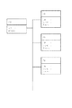
さらに、1つのCJには複数のPJを設定することができる。具体的には、ジョブ設定部32があるCJに対してPJの設定を受け付けた後、ユーザーは当該CJにつき、さらに別のPJを設定するか否かの選択を行い、新たに生成したPJに対して同様の設定(レシピの設定やウエハWの設定)を行うことができる。新たにPJが設定されると、ジョブ設定部32が受け付ける。この結果、図2に示すように、1つのCJに1つまたは複数のPJを設定することが可能となる。
Furthermore, a plurality of PJs can be set for one CJ. Specifically, after accepting the PJ setting for a CJ with the
例えば図3(a)は、1つのFOUP1に対して、「PJ1−1」と「PJ1−2」との2つのPJを含む「CJ1」が設定された例を示しており、図3(b)は、1つのFOUP2に対して、ただ一つの「PJ2−1」を含む「CJ2」が設定された例を示している。
動作確認モードでは、FOUP1〜4からウエハWを取り出し、搬送スケジュールに従って各洗浄モジュール2にウエハWを搬送し、元のFOUP1〜4に戻す搬送動作のみを行い、実際のスクラブ洗浄は行わない場合や、ウエハWの搬送及びスクラブ洗浄の双方を実行する場合などの様々なPJの設定をすることができる。
For example, FIG. 3A shows an example in which “CJ1” including two PJs “PJ1-1” and “PJ1-2” is set for one FOUP1, and FIG. ) Shows an example in which “CJ2” including only one “PJ2-1” is set for one FOUP2.
In the operation confirmation mode, the wafer W is taken out from the
ここで処理モードと、動作確認モードとにおけるウエハWの取り扱いの最も大きな違いを説明する。処理モードにおいては、前段の処理装置にて処理された製品ウエハWを収納したFOUP1〜4が載置台上に載置される。そしてここから取り出されたウエハWが洗浄モジュール2にて処理され、再び元のFOUP1〜4に収納されると、当該FOUP1〜4は、後段の処理装置へと搬出される。こうして載置台には次々と新たなFOUP1〜4が搬送されてくる。
Here, the largest difference in handling of the wafer W between the processing mode and the operation confirmation mode will be described. In the processing mode, the
これに対して動作確認モードは、第1、第2のウエハ搬送機構15、17や洗浄モジュール2などの動作確認を行うことが目的であるため、載置台上のFOUP1〜4を交換せずに、同じウエハWを繰り返し取り出してPJを実行してもよい。そこで本例の制御部3は、先に説明したモード選択部31やジョブ設定部32の機能に加えCJ回数設定部33を備え、各FOUP1〜4に設定されたCJの実行回数を設定することができる。この結果、例えば25枚のウエハWを収納した4台のFOUP1〜4(ウエハW枚数は100枚)に対して合計10回のCJを実行すれば、処理モードにて1000枚の製品ウエハWを処理したときと同様の条件下で動作確認を行うことができる。
On the other hand, the operation confirmation mode is intended to confirm the operations of the first and second
こうしてCJ回数設定部33にてCJの実行回数が設定されると、制御部3は、予め指定された順番で周期的にCJを実行し、設定回数のCJを実行した後に動作確認モードを終了する。本例では、載置台の左端から順番にFOUP1〜4が載置され、FOUPの番号の小さい方から順番に設定されたCJが周期的に実行されるものとする。ここでCJを「周期的に実行する」とは、処理が終了したウエハWを収容したFOUPを洗浄装置1の外へ搬出することなく、複数回の処理を行うことをいう。
When the number of CJ executions is set by the CJ
そして制御部3は、相前後する順番で実行されるCJに含まれるPJを並列で実行することが可能な場合には、これらのPJを並列して実行し、並列で実行することが可能でない場合には、前記の順番通りにPJを実行する。この機能の具体例については、以下の動作説明にて図4〜図10を参照しながら詳細に説明する。
When the
まず、図4に基づき、動作確認モード時の洗浄装置1の動作について説明する。ユーザーが運転操作部18を操作して、洗浄装置1の動作確認モードを選択する(図4、スタート)。ユーザーの操作を受けてCJが生成され、ジョブ設定部32がIDの自動付与やFOUP1〜4の選択を受け付けて、当該CJの設定を行い(ステップS1)、当該CJについてPJを1つ生成してIDの自動付与を行う(ステップS2)。次いで、ジョブ設定部32は、ユーザーが行ったレシピの設定(ステップS3)やウエハWの設定(ステップS4)を受け付けて、生成されたPJとして設定する。次いで、当該CJについて新たなPJを追加するか否かの選択を受け付ける(ステップS5)。
First, based on FIG. 4, operation | movement of the washing | cleaning
ユーザーによってPJを追加することが選択された場合には(ステップS5;YES)、ジョブ設定部32は運転操作部18の画面などにPJの設定エリアを追加し(ステップS6)、レシピやウエハWの設定を受け付けて、生成された新たなPJとして設定する(ステップS2〜4)。こうして必要な数だけPJを追加し、これ以上PJを追加しない場合には(ステップS5;NO)、当該動作確認モードに新たなCJを追加するか否かの選択を受け付ける(ステップS7)。
If the user selects to add a PJ (step S5; YES), the
ユーザーによってCJを追加することが選択された場合には(ステップS7;YES)、ジョブ設定部32は運転操作部18の画面などにCJの設定エリアを追加し(ステップS8)、各PJについてのレシピやウエハWの設定動作を繰り返し、新たなCJ、PJ(及び追加PJ)として設定する(ステップS1〜S6)。
If the user selects to add CJ (step S7; YES), the
そして必要な数だけCJを追加し、これ以上CJを追加しない場合には(ステップS7;NO)、CJ回数設定部33はCJの実行回数の設定を受け付ける(ステップS9)。しかる後、制御部3は、各CJに設定されたPJの内容、CJの実行回数に基づいて、各FOUP1〜4内のウエハWの搬送スケジュールを作成する(ステップS10)。
When the required number of CJs is added and no more CJs are added (step S7; NO), the CJ
搬送スケジュールが作成されると、各FOUP1〜4からはウエハWが取り出され、当該搬送スケジュールに基づいて各処理モジュール2に搬送され、各PJに設定されているレシピに応じた確認運転用の処理が実行される(ステップS11)。そして、前記の設定回数だけCJを実行したら、洗浄装置1は動作確認モードの運転を終える(エンド)。
When the transfer schedule is created, the wafer W is taken out from each of the
次に、図5、図6を参照しながら、CJを並列で実行することが可能でない場合の動作確認モードの運転例について説明する。本例では、洗浄装置1の載置台には、2つのFOUP1、2が配置され、図3に示すようにFOUP1には、PJ1−1、PJ1−2の2つのPJを含むCJ1が設定され、FOUP2にはPJ2−1からなるPJを1つだけ含むCJ2が設定されているものとする。そして、当該動作確認モードでは、これらCJ1、CJ2を合計8回実行するものとする。
Next, an example of operation in the operation confirmation mode when CJ cannot be executed in parallel will be described with reference to FIGS. 5 and 6. In this example, two
図5は、各PJの実行スケジュールを示したタイムチャートであり、時間の経過方向が下向きとなっている。図中、TRS1、2は、FOUP1、2から洗浄モジュール2への搬出時に使用される受け渡し棚16のスロット、TRS3、4は洗浄モジュール2からFOUP1、2への搬入時に使用される受け渡し棚16のスロット、SCR1〜3は、各PJで使用される洗浄モジュール2を表している。下向きの矢印は、その洗浄モジュール2での処理が継続していることを示している。
FIG. 5 is a time chart showing the execution schedule of each PJ, and the time passage direction is downward. In the figure,
各PJで使用される受け渡し棚16のスロット位置(TRS1〜4)や洗浄モジュール2(SCR1〜3)は、CJ、PJの設定を行った後、制御部3が搬送スケジュールを作成する時に設定される。なお、TRS1〜4、SCR1〜3などの番号の違いは、搬送スケジュール上の管理番号であり、必ずしも異なるスロット位置や異なる洗浄モジュール2を使用することを意味するものではない。ここで図5に示す動作確認モードでは、例えば洗浄モジュール2のスクラバに供給される処理液を切り替える必要がある場合やレシピ上の搬送経路が重なる場合などには、制御部3はCJ1に含まれるPJ1−1、PJ1−2と、CJ2に含まれるPJ2−1とを並列で実行することが可能でない。すなわち、制御部3はCJ1とCJ2を並列して実行することが可能でない。
The slot positions (TRS1 to TRS4) and the cleaning modules 2 (SCR1 to SCR3) of the
ここで、「レシピ上の搬送経路」とは、第1、第2のウエハ搬送機構15、17や受け渡し棚16の各スロット、洗浄モジュール2などの各機器を介してウエハWが搬送される経路のことである。あるウエハWに対して設定された搬送経路上の機器が、当該ウエハWにより占有されている期間中は、他のウエハWが当該占有中の機器を用いる搬送経路を構成することはできない。具体的には、あるPJに基づいて洗浄モジュール2にてウエハWを処理している期間中は、別のPJが設定されている別のウエハWが当該洗浄モジュール2に搬送されることはできない。また、あるPJに基づいて受け渡し棚16のあるスロットにウエハWが載置されている期間中は、別のPJが設定されている別のウエハWが当該スロットに載置されることはできない。このような場合は、制御部3はそれぞれのPJを含むCJを並列して実行することが可能でない。
Here, the “transport route on the recipe” refers to a route through which the wafer W is transported via the first and second
図5に示すように、制御部3はFOUP1、2の番号の小さい方に設定されているCJから順番に、CJ1(1回目)→CJ2(1回目)→CJ1(2回目)→と、周期的にCJを実行する。従って各PJは、PJ1−1→PJ1−2→PJ2−1→PJ1−1→…の順番に実行されることになる。
As shown in FIG. 5, the
図5に示したスケジュールに基づいてPJを実行するため、制御部3は、図6のタイムチャートに示すように各CJとその実行回数とを対応付けて、実行するCJの生成、消滅を行う。図中の白丸は、実行するCJの生成動作、黒丸はその消滅動作、点線は装置リソース待機、右向きの矢印は、ウエハWの搬送や処理の実行を示している。
In order to execute the PJ based on the schedule shown in FIG. 5, the
まず、動作確認モードの運転開始の際、制御部3は、CJの設定時に生成したIDに対し、CJの実行回数に対応する符号を付し(例えば3桁の数字を1ずつ増やして付与し)、実行するCJのIDを生成する。本例では番号の小さいFOUP1に設定されたCJ1から実行するので、始めに実行されるCJのIDは「CJ1−001」、次に実行されるCJのIDは「CJ2−002」となる。
First, at the start of operation in the operation confirmation mode, the
そして、制御部3は、CJ1−001とCJ2−002を並列して実行することができるかどうかを判断する。本例では、CJ2−002に設定されたPJ2−1は、CJ1−001に設定されたPJ1−1、PJ1−2と並列して実行することが可能でない。従って、制御部3は、CJ1−001につき、PJ1−1、PJ1−2の処理を実行する一方、これらPJ1−1、PJ1−2と並列して実行することが可能でないPJ2−1を含むCJ2−002については、装置リソースの待機状態とする。そして、CJ1−001に含まれるPJの処理が終了したら、CJ2−002のPJ2−1を実行する。
Then, the
CJ1−001の実行が終わったら、制御部3は当該CJを消滅させ、CJ2−002に次いで周期的に実行されるCJである「CJ1−003」のIDを持つCJを同じFOUPに対して生成させる。そして、制御部3は次に実行するCJが新たに生成されたタイミングで、実行中のCJと、並列で実行することが可能かどうか判断する。本実施例では、CJ1−003が生成された時点では、並列で実行することが可能でないCJ2−002が実行中のため、CJ1−003は実行開始されず、CJ2−002が終了してからCJ1−003が実行される。
When the execution of CJ1-001 is completed, the
このようにして、実行が完了したCJを消滅させ、次に実行するCJを新たに生成することにより、載置台上のFOUP1、2が仮想的に洗浄装置1外に搬出され交換されたものと取り扱われ、同じFOUPに対して設定回数に応じたCJを実行することができる。図6に示した例では、8回目のCJに対応するCJ2−008が実行されたら、制御部3は動作確認モードの実行を終える。
In this way, by deleting the CJ that has been executed and newly generating the CJ to be executed next, the
例えば図7、図8は、載置台上の4つのFOUP1〜4に各々CJ1〜CJ4が設定され、各CJには互いに並列して実行することが可能でない1つのPJ(PJ1−1〜PJ4−1)が設定されているときに、CJ1〜CJ4を合計7回実行する場合の動作を示している。 For example, in FIGS. 7 and 8, CJ1 to CJ4 are set in four FOUP1 to FOUP4 on the mounting table, respectively, and one CJ (PJ1-1 to PJ4-) that cannot be executed in parallel with each other. The operation when CJ1 to CJ4 are executed a total of seven times when 1) is set is shown.
この例では、制御部3は、動作確認モードの運転開始の際、図8に示すようにCJ1−001〜CJ1−004を生成し、各CJを並列して実行することが可能かどうか判断する。そして、各CJには互いに並列して実行することが可能でないPJが設定されているので、PJ1−1〜PJ4−1が並列して実行されないようにこれらのCJを実行する。制御部3は、FOUP1〜4の番号の小さい順から、実行するCJを周期的に生成し、7回目のCJであるCJ3−007が実行されたら、動作確認モードの実行を終える。
In this example, the
次に、CJを並列して実行することが可能な場合の動作確認モードの運転例について説明する。本例では、洗浄装置1の載置台には、2つのFOUP1、2が配置され、FOUP1には、PJ1−1からなる1つのPJを含むCJ1が設定され、FOUP2にはPJ2−1からなる1つのPJを含むCJ2が設定されている。そして、動作確認モードでは、これらCJ1、CJ2を合計6回実行するものとする。
Next, an operation example in the operation confirmation mode when CJ can be executed in parallel will be described. In this example, two
さらに本例の動作確認モードでは、例えば洗浄モジュール2のスクラバに供給される処理液が共通である場合や、レシピ上の搬送経路が重ならない場合などには、各CJに含まれるPJ1−1とPJ2−1とを並列して実行することが可能である。すなわち、制御部3はCJ1とCJ2を並列して実行することが可能である。また、PJ1−1の処理時間は、PJ2−1の処理時間よりも長くなっている。
Furthermore, in the operation check mode of this example, for example, when the processing liquid supplied to the scrubber of the
この場合には、図9に示すように、制御部3はCJ1(1回目)とCJ2(1回目)とを並列して実行する。処理時間が短いCJ2(1回目)が先に終了し、次のCJが生成される。このとき、番号の小さいFOUP1についてのCJ1(1回目)はまだ実行中なので、CJ1(2回目)の開始を追い越してFOUP2に対してCJ2(2回目)を開始する。その後、CJ1(1回目)が完了すると、予め割り当てられた順番に基づけば、CJ1の次のCJ2を開始することになるが、CJ2(2回目)が実行中なので、制御部3はCJ2(3回目)の開始を追い越してFOUP1に対してCJ1(2回目)を実行する。
In this case, as shown in FIG. 9, the
図9に示したスケジュールに基づいてPJを実行するため、図10のタイムチャートに示すように各CJとその実行回数とを対応付けて、実行されるCJの生成、消滅が行われる。まず、動作確認モードの運転開始時に、制御部3は、設定時に生成したCJのIDに対し、CJの実行回数に対応する符号を付して実行するCJのIDとして「CJ1−001、CJ2−002」を生成する。
In order to execute the PJ based on the schedule shown in FIG. 9, the CJ to be executed is generated and extinguished by associating each CJ with the number of times of execution as shown in the time chart of FIG. First, at the start of operation in the operation check mode, the
これらCJ1−001、CJ2−002に含まれるPJ1−1、PJ2−1は並列して実行することが可能なので、制御部3はこれらのCJを並列して実行し、処理時間の短いCJ2−002が先に終了する。処理を終えたCJ2−002については、当該CJを消滅させ、次に実行される「CJ2−003」のIDを持つCJを同じFOUP2に対して生成する。
Since the PJ1-1 and PJ2-1 included in the CJ1-001 and CJ2-002 can be executed in parallel, the
制御部3はCJ2−003を生成したタイミングで、実行中のCJ1−001と並列で実行することが可能かどうかを判断する。本実施例では、CJ2−003とCJ1−001は並列で実行することが可能なので、CJ2−003をCJ1−001と並列して実行する。CJ1−001が終了すると、当該CJを消滅させて、次に実行される「CJ1−004」のIDを持つCJを同じFOUP1に対して生成する。こうして図10に示すようにCJ1−001〜CJ2−006を生成して、処理が最後に終了するCJ1−006の実行が完了したら、動作確認モードを終える。
The
本実施の形態に係わる洗浄装置1によれば、以下の効果がある。制御部3は、動作確認用に設定された複数のCJのうち、順番が相前後するCJに含まれるPJを並列で実行することが可能であるか否かを判断する。そして、PJを並列で実行することが可能な場合には、これらのPJを並列して実行するので、CJを1つずつ実行する場合よりも短時間で動作確認運転を終了させることができ、効率的な試運転を行うことができる。また、予め設定された順番でPJを実行し、また同じ搬送容器から基板を繰り返し取り出して周期的にCJを実行する。これらにより、FOUPの交換を行わなくても実運転と同様の搬送スケジュールを組むことができ、実運転に近い効率的な試運転を行うことができる。
The
また、動作確認モードのCJの実行回数を予め設定できるので、動作確認運転に必要な量(ウエハWの処理枚数や動作確認運転の時間など)だけCJを実行することができる。これにより、動作確認モードの運転を自動的に停止することができ、ユーザーの立ち会いによる手動停止を必要としない。ここで、CJ回数設定部33にて設定されるCJの実行回数は、運転操作部18を介したユーザーからの指示などにより、途中で変更してもよい。
In addition, since the number of executions of the CJ in the operation check mode can be set in advance, the CJ can be executed by an amount necessary for the operation check operation (such as the number of processed wafers W and the time of the operation check operation). Thereby, the operation in the operation confirmation mode can be automatically stopped, and a manual stop by the presence of the user is not required. Here, the number of executions of CJ set by the CJ
更に、CJ回数設定部33にて設定された回数だけ実行される動作確認用のCJは、運転操作部18を介したユーザーからの指示や、搬送経路上の各機器(第1、第2のウエハ搬送機構15、17や洗浄モジュール2など)の不具合の検出などに応じて途中で停止するなどしてもよい。このとき、CJを停止する手法は、動作確認運転そのものを停止してもよいし、再開を前提とする中断をしてもよい。また、特定のCJだけを停止、中断して他のCJを継続したり、CJに含まれる特定のPJだけを停止、中断して他のPJを継続したりしてもよい。また、指定されたFOUPについてのCJを停止、中断し、他のFOUPについてはCJを継続してもよい。
Further, the operation confirmation CJ executed by the number of times set by the CJ
更にまた、動作確認運転(動作確認モード)のCJの実行の途中に、製品となるウエハWの処理を行う実運転(処理モード)のCJを割り込ませてもよい。動作確認運転中に急遽、実処理の必要なウエハWがきたとしても、実運転のCJを割り込ませることができるので、動作確認運転を止めることなく実処理も並列して行うことができる。 Furthermore, the CJ of the actual operation (processing mode) for processing the wafer W as a product may be interrupted during the execution of the CJ of the operation confirmation operation (operation confirmation mode). Even if a wafer W requiring actual processing suddenly arrives during the operation confirmation operation, the actual operation CJ can be interrupted, so that the actual processing can be performed in parallel without stopping the operation confirmation operation.
上述の実施の形態では、各FOUP1〜4についてCJを設定したが、CJの設定単位はこの例に限られない。例えば複数台のFOUP1〜4をまとめてCJを設定してもよい。また、CJを周期的に実行する順番は、上述の実施の形態に示したようにFOUP1〜4が載置台上に載置されている順番に実行する場合に限られるものではない。予め実行する順番が定められていれば、どのような順番であってもよい。
In the above-described embodiment, the CJ is set for each of the
そして、本発明の基板処理装置は、スクラブ洗浄を行う洗浄装置に限られるものではなく、例えば鉛直軸周りに回転する基板に処理液を供給して液処理を行う液処理モジュールをそなえた枚葉式の液処理装置に適用してもよい。また、共通の搬送機構に複数台の処理チャンバーを処理モジュールとして接続した、エッチング装置やアッシング装置などのプラズマ処理装置などにも本発明は適用することができる。 The substrate processing apparatus of the present invention is not limited to a cleaning apparatus that performs scrub cleaning. For example, a single wafer including a liquid processing module that supplies a processing liquid to a substrate that rotates about a vertical axis and performs liquid processing. You may apply to a liquid processing apparatus of a formula. Further, the present invention can also be applied to a plasma processing apparatus such as an etching apparatus or an ashing apparatus in which a plurality of processing chambers are connected as a processing module to a common transfer mechanism.
W ウエハ
1 洗浄装置
2 洗浄モジュール
3 制御部
31 モード選択部
32 ジョブ設定部
33 CJ回数設定部
Claims (21)
複数の基板を収納するための搬送容器を載置するための載置台と、
基板の処理を行うための複数の処理モジュールと、
前記載置台と前記処理モジュールとの間で基板を搬送するための基板搬送機構と、
少なくとも基板搬送機構または処理モジュールの動作確認運転を行うための動作確認モードを選択する選択部と、
動作確認用の複数のコントロールジョブを設定すると共に、これらコントロールジョブ毎に、前記搬送容器と当該搬送容器のスロットの位置とで特定される基板に対して実行するレシピを入力してプロセスジョブを設定するジョブ設定部と、
前記搬送容器を交換することなく当該搬送容器内に収納されている基板を繰り返し用いて、前記動作確認用の複数のコントロールジョブを、予め指定された順番でかつ周期的に実行する際に、全てのコントロールジョブの合計の実行回数を設定する回数設定部と、
前記選択部から動作確認モードが選択され、前記複数のコントロールジョブを実行する際に、一のコントロールジョブのレシピと順番が一つ後のコントロールジョブのレシピとが並列で実行可能か判断し、実行することが可能でない場合には、前記一のコントロールジョブの最終基板が搬送容器に収納された後、引き続いて前記順番が一つ後のコントロールジョブを実行する制御部と、を備えたことを特徴とする基板処理装置。 In a substrate processing apparatus for processing a plurality of substrates,
A mounting table for mounting a transport container for storing a plurality of substrates;
A plurality of processing modules for processing a substrate;
A substrate transport mechanism for transporting a substrate between the mounting table and the processing module;
A selection unit for selecting an operation confirmation mode for performing an operation confirmation operation of at least the substrate transport mechanism or the processing module;
Set up multiple control jobs for operation confirmation, and set up a process job for each of these control jobs by entering recipes to be executed on the substrate specified by the transfer container and the slot position of the transfer container A job setting section to
Repetitively using the substrates stored in the transfer container without exchanging the transfer container, and when executing a plurality of control jobs for checking the operation in a predetermined order and periodically A number setting section for setting the total number of executions of the control job,
Wherein the operation check mode is selected from the selection unit, when executing a plurality of control job, it is determined whether executable parallel and recipe control job after one recipe and order of one control job, execute If it is not possible, after the final substrate of the one control job is stored in a transport container, a control unit that subsequently executes the control job of the next one in order is provided. A substrate processing apparatus.
複数の基板を収納するための搬送容器を載置するための載置台と、 A mounting table for mounting a transport container for storing a plurality of substrates;
基板の処理を行うための複数の処理モジュールと、 A plurality of processing modules for processing a substrate;
前記載置台と前記処理モジュールとの間で基板を搬送するための基板搬送機構と、 A substrate transport mechanism for transporting a substrate between the mounting table and the processing module;
少なくとも基板搬送機構または処理モジュールの動作確認運転を行うための動作確認モードを選択する選択部と、 A selection unit for selecting an operation confirmation mode for performing an operation confirmation operation of at least the substrate transport mechanism or the processing module;
動作確認用の第1のコントロールジョブと第2のコントロールジョブとを設定すると共に、これらコントロールジョブ毎に、前記搬送容器と当該搬送容器のスロットの位置とで特定される基板に対して実行するレシピを入力してプロセスジョブを設定するジョブ設定部と、 A first control job and a second control job for operation confirmation are set, and a recipe to be executed for the substrate specified by the transfer container and the slot position of the transfer container for each control job. A job setting section to set process jobs by entering
前記搬送容器を交換することなく当該搬送容器内に収納されている基板を繰り返し用いて、前記動作確認用の第1、第2のコントロールジョブを、予め指定された順番でかつ周期的に実行する際に、全てのコントロールジョブの合計の実行回数を設定する回数設定部と、 The first and second control jobs for confirming the operation are periodically executed in a predetermined order by repeatedly using the substrate stored in the transfer container without replacing the transfer container. When setting the number of times to set the total number of executions of all control jobs,
前記選択部から動作確認モードが選択され、前記第1、第2のコントロールジョブを実行する際に、一のコントロールジョブのレシピと順番が一つ後のコントロールジョブのレシピとが並列で実行可能か判断し、実行可能な場合は、前記一のコントロールジョブと順番が一つ後のコントロールジョブとを並列に実行し、前記一のコントロールジョブのレシピが終了しない間に、並列で実行されている前記順番が一つ後のコントロールジョブが終了する場合は、前記終了していない一のコントロールジョブのレシピと、前記終了していない一のコントロールジョブと種別が異なり、かつ順番が後のコントロールジョブのレシピとが並列で実行可能か判断する制御部と、を備えたことを特徴とする基板処理装置。 When the operation check mode is selected from the selection unit and the first and second control jobs are executed, can the recipe of one control job and the recipe of the control job of the next order be executed in parallel? If it is determined and can be executed, the one control job and the control job whose order is one after are executed in parallel, and the recipe of the one control job is executed in parallel while the recipe is not completed. When a control job that is one order later is completed, the recipe for the control job that is of a different type and the recipe of the one control job that has not been completed is different from the recipe of the one control job that has not been completed. And a control unit that determines whether or not can be executed in parallel.
少なくとも基板搬送機構または処理モジュールの動作確認運転を行うための動作確認モードを選択する工程と、
動作確認用の複数のコントロールジョブを設定すると共に、これらコントロールジョブ毎に、前記搬送容器と当該搬送容器のスロットの位置とで特定される基板に対して実行するレシピを入力してプロセスジョブを設定する工程と、
前記搬送容器を交換することなく当該搬送容器内に収納されている基板を繰り返し用いて、前記動作確認用の複数のコントロールジョブを、予め指定された順番でかつ周期的に実行する際に、全てのコントロールジョブの合計の実行回数を設定する工程と、
動作確認モードが選択され、前記複数のコントロールジョブを実行する際に、一のコントロールジョブのレシピと、順番が一つ後のコントロールジョブのレシピとが並列で実行可能か判断する工程と、
実行することが可能でない場合には、前記一のコントロールジョブの最終基板が搬送容器に収納された後、引き続いて前記順番が一つ後のコントロールジョブを実行する工程と、を含むことを特徴とする基板処理方法。 A substrate for storing a plurality of substrates is placed on a mounting table, the substrate is taken out of the substrate by a substrate transport mechanism, processed by being transferred to one of a plurality of processing modules, and a substrate after processing. In the substrate processing method for returning the material to the original transport container
Selecting an operation confirmation mode for performing at least an operation confirmation operation of the substrate transfer mechanism or the processing module; and
Set up multiple control jobs for operation confirmation, and set up a process job for each of these control jobs by entering recipes to be executed on the substrate specified by the transfer container and the slot position of the transfer container And a process of
Repetitively using the substrates stored in the transfer container without exchanging the transfer container, and when executing a plurality of control jobs for checking the operation in a predetermined order and periodically A process for setting the total number of executions of the control job,
When the operation check mode is selected and the plurality of control jobs are executed, a step of determining whether the recipe of one control job and the recipe of the control job one order after can be executed in parallel;
If it is not possible to execute, after the final substrate of the one control job is stored in a transport container, the step of subsequently executing the next control job in the order , Substrate processing method.
少なくとも基板搬送機構または処理モジュールの動作確認運転を行うための動作確認モードを選択する工程と、 Selecting an operation confirmation mode for performing at least an operation confirmation operation of the substrate transfer mechanism or the processing module; and
動作確認用の第1のコントロールジョブと第2のコントロールジョブとを設定すると共に、これらコントロールジョブ毎に、前記搬送容器と当該搬送容器のスロットの位置とで特定される基板に対して実行するレシピを入力してプロセスジョブを設定する工程と、 A first control job and a second control job for operation confirmation are set, and a recipe to be executed for the substrate specified by the transfer container and the slot position of the transfer container for each control job. To set a process job by entering
前記搬送容器を交換することなく当該搬送容器内に収納されている基板を繰り返し用いて、前記動作確認用の第1、第2のコントロールジョブを、予め指定された順番でかつ周期的に実行する際に、全てのコントロールジョブの合計の実行回数を設定する工程と、 The first and second control jobs for confirming the operation are periodically executed in a predetermined order by repeatedly using the substrate stored in the transfer container without replacing the transfer container. When setting the total number of executions of all control jobs,
動作確認モードが選択され、前記第1、第2のコントロールジョブを実行する際に、一のコントロールジョブのレシピと、順番が一つ後のコントロールジョブのレシピとが並列で実行可能か判断する工程と、 When the operation check mode is selected and the first and second control jobs are executed, it is determined whether the recipe of one control job and the recipe of the control job one order after can be executed in parallel When,
実行可能な場合は、前記一のコントロールジョブと順番が一つ後のコントロールジョブとを並列に実行する工程と、 If it can be executed, the step of executing the one control job and the control job of the next one in parallel;
前記一のコントロールジョブのレシピが終了しない間に、並列で実行されている前記順番が一つ後のコントロールジョブが終了する場合は、前記終了していない一のコントロールジョブのレシピと、前記終了していない一のコントロールジョブと種別が異なり、かつ順番が後のコントロールジョブのレシピとが並列で実行可能か判断する工程と、を含むことを特徴とする基板処理方法。 If the control job that is executed in parallel before the one control job recipe does not end and the next control job ends, the one control job recipe that has not ended and the end And a step of determining whether the recipe of the control job whose type is different from that of the control job which is not in order and which can be executed in parallel can be executed in parallel.
前記プログラムは請求項11ないし20のいずれか一つに記載された基板処理方法を実行するためにステップが組まれていることを特徴とする記憶媒体。 A substrate for storing a plurality of substrates is placed on a mounting table, the substrate is taken out of the substrate by a substrate transport mechanism, processed by being transferred to one of a plurality of processing modules, and a substrate after processing. A storage medium storing a computer program used in the substrate processing apparatus for returning the original to the original transport container,
A storage medium, wherein the program has steps for executing the substrate processing method according to any one of claims 11 to 20 .
Priority Applications (4)
| Application Number | Priority Date | Filing Date | Title |
|---|---|---|---|
| JP2012038947A JP5821689B2 (en) | 2011-04-20 | 2012-02-24 | Substrate processing apparatus, substrate processing method, and storage medium |
| TW101113942A TWI525733B (en) | 2011-04-20 | 2012-04-19 | A substrate processing apparatus, a substrate processing method, and a memory medium |
| US13/450,590 US9396978B2 (en) | 2011-04-20 | 2012-04-19 | Substrate processing apparatus, substrate processing method and storage medium |
| KR1020120040979A KR101842242B1 (en) | 2011-04-20 | 2012-04-19 | Substrate processing apparatus, substrate processing method and storage medium |
Applications Claiming Priority (3)
| Application Number | Priority Date | Filing Date | Title |
|---|---|---|---|
| JP2011094015 | 2011-04-20 | ||
| JP2011094015 | 2011-04-20 | ||
| JP2012038947A JP5821689B2 (en) | 2011-04-20 | 2012-02-24 | Substrate processing apparatus, substrate processing method, and storage medium |
Publications (3)
| Publication Number | Publication Date |
|---|---|
| JP2012235087A JP2012235087A (en) | 2012-11-29 |
| JP2012235087A5 JP2012235087A5 (en) | 2014-03-06 |
| JP5821689B2 true JP5821689B2 (en) | 2015-11-24 |
Family
ID=47021940
Family Applications (1)
| Application Number | Title | Priority Date | Filing Date |
|---|---|---|---|
| JP2012038947A Active JP5821689B2 (en) | 2011-04-20 | 2012-02-24 | Substrate processing apparatus, substrate processing method, and storage medium |
Country Status (4)
| Country | Link |
|---|---|
| US (1) | US9396978B2 (en) |
| JP (1) | JP5821689B2 (en) |
| KR (1) | KR101842242B1 (en) |
| TW (1) | TWI525733B (en) |
Families Citing this family (11)
| Publication number | Priority date | Publication date | Assignee | Title |
|---|---|---|---|---|
| JP5006122B2 (en) | 2007-06-29 | 2012-08-22 | 株式会社Sokudo | Substrate processing equipment |
| JP5128918B2 (en) * | 2007-11-30 | 2013-01-23 | 株式会社Sokudo | Substrate processing equipment |
| JP5001828B2 (en) | 2007-12-28 | 2012-08-15 | 株式会社Sokudo | Substrate processing equipment |
| JP5179170B2 (en) | 2007-12-28 | 2013-04-10 | 株式会社Sokudo | Substrate processing equipment |
| JP6097569B2 (en) * | 2013-01-17 | 2017-03-15 | 株式会社Screenセミコンダクターソリューションズ | Substrate processing apparatus and substrate processing row control method |
| JP5987796B2 (en) * | 2013-07-24 | 2016-09-07 | 東京エレクトロン株式会社 | Substrate processing apparatus, substrate processing method, and storage medium |
| JP6216193B2 (en) * | 2013-09-11 | 2017-10-18 | 株式会社荏原製作所 | Unit control panel, substrate transfer test method, and substrate processing apparatus |
| US10522472B2 (en) | 2016-09-08 | 2019-12-31 | Asml Netherlands B.V. | Secure chips with serial numbers |
| US10079206B2 (en) | 2016-10-27 | 2018-09-18 | Mapper Lithography Ip B.V. | Fabricating unique chips using a charged particle multi-beamlet lithography system |
| JP7170438B2 (en) * | 2018-07-03 | 2022-11-14 | 東京エレクトロン株式会社 | SUBSTRATE PROCESSING APPARATUS AND JUDGMENT METHOD |
| JP7454467B2 (en) | 2020-08-03 | 2024-03-22 | 株式会社荏原製作所 | Substrate processing system, control device for the substrate processing system, and operating method for the substrate processing system |
Family Cites Families (9)
| Publication number | Priority date | Publication date | Assignee | Title |
|---|---|---|---|---|
| US6714832B1 (en) * | 1996-09-11 | 2004-03-30 | Hitachi, Ltd. | Operating method of vacuum processing system and vacuum processing system |
| JP2001093791A (en) * | 1999-09-20 | 2001-04-06 | Hitachi Ltd | Operation of vacuum treatment equipment and method for processing wafer |
| US6618682B2 (en) * | 2001-04-20 | 2003-09-09 | International Business Machines Corporation | Method for test optimization using historical and actual fabrication test data |
| JP4557986B2 (en) * | 2004-11-24 | 2010-10-06 | 株式会社日立国際電気 | Substrate processing apparatus and semiconductor device manufacturing method |
| US9305814B2 (en) * | 2004-12-20 | 2016-04-05 | Tokyo Electron Limited | Method of inspecting substrate processing apparatus and storage medium storing inspection program for executing the method |
| JP4560022B2 (en) * | 2006-09-12 | 2010-10-13 | 東京エレクトロン株式会社 | Coating, developing device, coating and developing device control method, and storage medium |
| JP4828503B2 (en) * | 2007-10-16 | 2011-11-30 | 東京エレクトロン株式会社 | Substrate processing apparatus, substrate transfer method, computer program, and storage medium |
| JP5552265B2 (en) * | 2009-06-24 | 2014-07-16 | 東京エレクトロン株式会社 | Substrate processing apparatus control method and storage medium |
| JP5575507B2 (en) * | 2010-03-02 | 2014-08-20 | 株式会社日立国際電気 | Substrate processing apparatus, substrate transport method, semiconductor device manufacturing method, and substrate processing apparatus maintenance method |
-
2012
- 2012-02-24 JP JP2012038947A patent/JP5821689B2/en active Active
- 2012-04-19 KR KR1020120040979A patent/KR101842242B1/en active IP Right Grant
- 2012-04-19 TW TW101113942A patent/TWI525733B/en active
- 2012-04-19 US US13/450,590 patent/US9396978B2/en active Active
Also Published As
| Publication number | Publication date |
|---|---|
| TW201308477A (en) | 2013-02-16 |
| KR101842242B1 (en) | 2018-05-14 |
| US9396978B2 (en) | 2016-07-19 |
| JP2012235087A (en) | 2012-11-29 |
| KR20120120051A (en) | 2012-11-01 |
| US20120271444A1 (en) | 2012-10-25 |
| TWI525733B (en) | 2016-03-11 |
Similar Documents
| Publication | Publication Date | Title |
|---|---|---|
| JP5821689B2 (en) | Substrate processing apparatus, substrate processing method, and storage medium | |
| JP5852908B2 (en) | Schedule creation method and schedule creation program for substrate processing apparatus | |
| JP5445006B2 (en) | Substrate processing apparatus, substrate processing method, and storage medium | |
| KR101536842B1 (en) | Substrate processing device, alarm management method of substrate processing device and computer-readable storage medium | |
| JP5627518B2 (en) | Substrate processing apparatus and power management method | |
| KR101840578B1 (en) | Substrate processing method and substrate processing device | |
| JP2013038126A (en) | Substrate processing apparatus, substrate processing method, and storage medium | |
| WO2015198885A1 (en) | Schedule preparation method for substrate processing device and substrate processing device | |
| TW201513251A (en) | Scheduling method and recording medium recording scheduling program for substrate processing apparatus | |
| KR101849735B1 (en) | Substrate processing apparatus, substrate transfer method and storage medium | |
| KR20100088090A (en) | Liquid processing apparatus | |
| JP6481977B2 (en) | Substrate processing method and substrate processing apparatus | |
| JP6499563B2 (en) | Substrate processing apparatus schedule creation method and program thereof | |
| KR102185873B1 (en) | Substrate processing apparatus, substrate processing method and storage medium | |
| JP5847515B2 (en) | Schedule creation method and schedule creation program for substrate processing apparatus | |
| JP2003086481A (en) | Method for creating schedule of substrate processing apparatus and program therefor | |
| US10483139B2 (en) | Substrate processing apparatus, method of operating the same and non-transitory storage medium | |
| JP6079510B2 (en) | Substrate processing system, substrate processing method, and storage medium | |
| JP3960761B2 (en) | Substrate processing apparatus schedule creation method and program thereof | |
| KR20220002126A (en) | Substrate treatment method and substrate treatment apparatus | |
| JP2015128808A (en) | Control device of substrate treatment device and substrate treatment device |
Legal Events
| Date | Code | Title | Description |
|---|---|---|---|
| A521 | Request for written amendment filed |
Free format text: JAPANESE INTERMEDIATE CODE: A523 Effective date: 20140120 |
|
| A621 | Written request for application examination |
Free format text: JAPANESE INTERMEDIATE CODE: A621 Effective date: 20140120 |
|
| A977 | Report on retrieval |
Free format text: JAPANESE INTERMEDIATE CODE: A971007 Effective date: 20141225 |
|
| A131 | Notification of reasons for refusal |
Free format text: JAPANESE INTERMEDIATE CODE: A131 Effective date: 20150106 |
|
| A521 | Request for written amendment filed |
Free format text: JAPANESE INTERMEDIATE CODE: A523 Effective date: 20150309 |
|
| TRDD | Decision of grant or rejection written | ||
| A01 | Written decision to grant a patent or to grant a registration (utility model) |
Free format text: JAPANESE INTERMEDIATE CODE: A01 Effective date: 20150908 |
|
| A61 | First payment of annual fees (during grant procedure) |
Free format text: JAPANESE INTERMEDIATE CODE: A61 Effective date: 20150921 |
|
| R150 | Certificate of patent or registration of utility model |
Ref document number: 5821689 Country of ref document: JP Free format text: JAPANESE INTERMEDIATE CODE: R150 |
|
| R250 | Receipt of annual fees |
Free format text: JAPANESE INTERMEDIATE CODE: R250 |
|
| R250 | Receipt of annual fees |
Free format text: JAPANESE INTERMEDIATE CODE: R250 |
|
| R250 | Receipt of annual fees |
Free format text: JAPANESE INTERMEDIATE CODE: R250 |
|
| R250 | Receipt of annual fees |
Free format text: JAPANESE INTERMEDIATE CODE: R250 |
|
| R250 | Receipt of annual fees |
Free format text: JAPANESE INTERMEDIATE CODE: R250 |
|
| R250 | Receipt of annual fees |
Free format text: JAPANESE INTERMEDIATE CODE: R250 |