JP5785838B2 - Closed hole opening method and closed hole opening device - Google Patents
Closed hole opening method and closed hole opening device Download PDFInfo
- Publication number
- JP5785838B2 JP5785838B2 JP2011210737A JP2011210737A JP5785838B2 JP 5785838 B2 JP5785838 B2 JP 5785838B2 JP 2011210737 A JP2011210737 A JP 2011210737A JP 2011210737 A JP2011210737 A JP 2011210737A JP 5785838 B2 JP5785838 B2 JP 5785838B2
- Authority
- JP
- Japan
- Prior art keywords
- opening
- plug
- hole
- mud material
- closing
- Prior art date
- Legal status (The legal status is an assumption and is not a legal conclusion. Google has not performed a legal analysis and makes no representation as to the accuracy of the status listed.)
- Active
Links
- 238000000034 method Methods 0.000 title claims description 54
- 239000000463 material Substances 0.000 claims description 89
- 238000002347 injection Methods 0.000 claims description 17
- 239000007924 injection Substances 0.000 claims description 17
- 238000010304 firing Methods 0.000 claims description 10
- 230000000903 blocking effect Effects 0.000 description 19
- 229910052751 metal Inorganic materials 0.000 description 13
- 239000002184 metal Substances 0.000 description 13
- XEEYBQQBJWHFJM-UHFFFAOYSA-N Iron Chemical compound [Fe] XEEYBQQBJWHFJM-UHFFFAOYSA-N 0.000 description 6
- 238000005553 drilling Methods 0.000 description 4
- 239000003921 oil Substances 0.000 description 4
- 229910052742 iron Inorganic materials 0.000 description 3
- 238000012986 modification Methods 0.000 description 3
- 230000004048 modification Effects 0.000 description 3
- 230000002093 peripheral effect Effects 0.000 description 3
- XLYOFNOQVPJJNP-UHFFFAOYSA-N water Substances O XLYOFNOQVPJJNP-UHFFFAOYSA-N 0.000 description 3
- 229910000805 Pig iron Inorganic materials 0.000 description 2
- PNEYBMLMFCGWSK-UHFFFAOYSA-N aluminium oxide Inorganic materials [O-2].[O-2].[O-2].[Al+3].[Al+3] PNEYBMLMFCGWSK-UHFFFAOYSA-N 0.000 description 2
- 239000004927 clay Substances 0.000 description 2
- 230000001681 protective effect Effects 0.000 description 2
- HBMJWWWQQXIZIP-UHFFFAOYSA-N silicon carbide Chemical compound [Si+]#[C-] HBMJWWWQQXIZIP-UHFFFAOYSA-N 0.000 description 2
- 229910010271 silicon carbide Inorganic materials 0.000 description 2
- 239000007787 solid Substances 0.000 description 2
- 229910000831 Steel Inorganic materials 0.000 description 1
- 229910052782 aluminium Inorganic materials 0.000 description 1
- XAGFODPZIPBFFR-UHFFFAOYSA-N aluminium Chemical compound [Al] XAGFODPZIPBFFR-UHFFFAOYSA-N 0.000 description 1
- QVGXLLKOCUKJST-UHFFFAOYSA-N atomic oxygen Chemical compound [O] QVGXLLKOCUKJST-UHFFFAOYSA-N 0.000 description 1
- 238000009412 basement excavation Methods 0.000 description 1
- 239000011230 binding agent Substances 0.000 description 1
- 238000004891 communication Methods 0.000 description 1
- 238000001514 detection method Methods 0.000 description 1
- 230000009969 flowable effect Effects 0.000 description 1
- 239000012530 fluid Substances 0.000 description 1
- 238000003780 insertion Methods 0.000 description 1
- 230000037431 insertion Effects 0.000 description 1
- 238000004519 manufacturing process Methods 0.000 description 1
- 239000000203 mixture Substances 0.000 description 1
- 229910052760 oxygen Inorganic materials 0.000 description 1
- 239000001301 oxygen Substances 0.000 description 1
- 239000011819 refractory material Substances 0.000 description 1
- 239000011347 resin Substances 0.000 description 1
- 229920005989 resin Polymers 0.000 description 1
- 239000010959 steel Substances 0.000 description 1
Images


Classifications
-
- C—CHEMISTRY; METALLURGY
- C21—METALLURGY OF IRON
- C21B—MANUFACTURE OF IRON OR STEEL
- C21B7/00—Blast furnaces
- C21B7/12—Opening or sealing the tap holes
Landscapes
- Engineering & Computer Science (AREA)
- Chemical & Material Sciences (AREA)
- Manufacturing & Machinery (AREA)
- Materials Engineering (AREA)
- Metallurgy (AREA)
- Organic Chemistry (AREA)
- Furnace Charging Or Discharging (AREA)
- Blast Furnaces (AREA)
Description
本発明は、高炉の炉壁に形成された出銑口を閉塞するとともに閉塞された出銑口を開孔する閉塞開孔方法および閉塞開孔装置に関する。 The present invention relates to a closing opening method and a closing opening device for closing an opening formed in a furnace wall of a blast furnace and opening the closed opening.
製鉄設備の一つである高炉では、鉄鉱石に含まれる酸素を還元することで銑鉄が取り出される。高炉の炉底の湯溜まり部に溜まる溶銑(溶融した銑鉄)は、湯溜まり部横の炉壁に設けられた出銑口から取り出される。出銑口は、マッド材と呼ばれる粘土状の耐火物を充填して焼成させることによって閉塞される。溶銑の取り出しは、空圧式もしくは油圧式の開孔機を使用して、錐ロッドに前後進、打撃、回転の動作をさせることにより、出銑口に充填されている閉塞材を開孔することにより行われる。溶銑を湯溜まり部から取り出した後は、マッドガンを使用してマッド材を出銑口に充填して焼成させて出銑口を閉塞する。このように、出銑口の開孔と閉塞作業には、開孔機およびマッドガンというそれぞれ専用の装置を使用している。 In a blast furnace, which is one of the iron making facilities, pig iron is taken out by reducing oxygen contained in iron ore. The hot metal (molten pig iron) collected in the hot water pool at the bottom of the blast furnace is taken out from a tap outlet provided on the furnace wall beside the hot water pool. The taphole is closed by filling and firing a clay-like refractory called mud material. To remove hot metal, use a pneumatic or hydraulic opening machine to open and close the plugging material filled in the spout by moving the conical rod back and forth, hitting, and rotating. Is done. After the hot metal is taken out from the hot water reservoir, a mud gun is used to fill the mud material into the spout and fire it to close the spout. As described above, the opening and closing operations of the tap holes are performed using dedicated devices such as a hole opening machine and a mud gun, respectively.
これらの装置による出銑口の開孔と閉塞作業は、自動化の試みもなされているが、特に開孔作業は開孔判定が難しいことから、開孔の最終的な判断は装置の使用者に委ねられている。これは、出銑口の炉内側のマッド材の形状が一定していないこと、出銑口内に充填されたマッド材の内部状態が不均一であることに起因する。出銑口に充填されるマッド材は、通常、炉内側に凸の状態で固結するが、前回の開孔作業によって削孔された出銑口の炉内側の状態や充填されるマッド材の量によってその形状は異なるため、出銑口の炉内側に付着したマッド材のうち最も炉内側の位置が一律にならない。このため、出銑口の削孔深さに基づいて開孔判定を行うことが困難になり、開孔判定が難しくなっている。
また、充填されたマッド材は、その内部に空隙ができることもあり、錐ロッドの前進負荷や回転負荷に基づいて開孔判定を行うと、空隙によって前進負荷や回転負荷が弱まることで出銑口が貫通したと誤判定してしまう恐れがある。
このように、出銑口の開孔判定を容易にするためには、出銑口の閉塞状態を常に一定に保つことが要求される。
Although attempts to automate the opening and closing work of the spout with these devices have been attempted, it is difficult for the user of the device to make a final determination of the opening because it is particularly difficult to determine the opening. It is entrusted. This is due to the fact that the shape of the mud material inside the furnace at the tap outlet is not constant, and the internal state of the mud material filled in the tap outlet is non-uniform. The mud material filled in the tap is usually consolidated in a convex state on the inside of the furnace, but the state of the inside of the furnace at the tap and the mud filled Since the shape differs depending on the amount, the position inside the furnace is not uniform among the mud materials adhering to the furnace inside of the tap outlet. For this reason, it is difficult to make a hole determination based on the drilling depth of the tap hole, and the hole determination is difficult.
In addition, the filled mud material may have a gap in its interior, and if the hole detection is performed based on the forward load or rotational load of the conical rod, the forward load or rotational load will be weakened by the gap, and the spout will be opened. There is a risk of misjudging that has penetrated.
Thus, in order to facilitate the determination of the opening of the tap opening, it is required to always keep the closing state of the tap opening constant.
出銑口の閉塞技術の例としては、たとえば、特許文献1に記載された高炉出銑口の閉塞方法が知られている。この閉塞方法は、出銑口へマッド材を充填し、このマッド材の焼成中にマッド材の中途まで大口径の孔を掘り、この大口径孔に再びマッド材を充填する方法である。この閉塞方法によれば、後から充填するマッド材により出銑口におけるマッド材の充填密度を向上させることができるという。 As an example of the taphole closing technique, for example, a blast furnace outlet closing method described in Patent Document 1 is known. This closing method is a method in which a mud material is filled into a spout, a large-diameter hole is dug to the middle of the mud material during firing of the mud material, and the large-diameter hole is filled again with the mud material. According to this closing method, the filling density of the mud material at the spout can be improved by the mud material filled later.
また、閉塞技術の他の例として、特許文献2に記載された高炉出銑口形成方法がある。この形成方法は、出銑口にマッド材を充填してマッド材が炉熱によって焼成された後、開孔用ビットで、溶銑の噴出を防ぐのに必要な厚さを残して削孔し、開孔内に流動性耐火物を適量注入して、予め形成固化した耐火物筒状体を開孔内に挿入して開孔内側と耐火物筒状体外側との隙間に前記流動性耐火物を充填させる方法である。
本形成方法によれば、耐火物筒状体の内部が空洞のため開孔に要する時間を短縮することができる。また、焼成したマッド材を開孔した後に耐火物筒状体を挿入させるため、小さな挿入力で済み、従来の出銑口開孔機のフィード力で挿入することができるとされる。
As another example of the closing technique, there is a blast furnace outlet forming method described in
According to this forming method, the time required for opening can be shortened because the inside of the refractory cylinder is hollow. Further, since the refractory cylindrical body is inserted after opening the fired mud material, a small insertion force is required, and it can be inserted with the feed force of a conventional tap hole opening machine.
出銑口を開孔させるのに要する削孔深さを一定にした方法として、特許文献3に記載された冶金炉用出湯口の開閉方法が知られている。この方法では、芯金棒の周囲に出銑口の断面形状より僅かに大きい断面形状で柱状に形成した固形マッド材を芯金棒とともに出銑口に打ち込んで閉塞し、芯金棒を引き抜いて開孔する。 As a method of making the drilling depth required to open the tap hole constant, a method for opening and closing the metallurgical furnace tap port described in Patent Document 3 is known. In this method, a solid mud material formed in a column shape with a cross-sectional shape slightly larger than the cross-sectional shape of the spout opening around the core bar is driven and closed together with the core bar, and the core bar is pulled out to open the hole. .
しかしながら、特許文献1および特許文献2に記載の方法では、以前に充填したマッド材が高炉内に溜まって出銑口の炉内側の開口に達しているため、出銑口を開孔させるために必要な削孔深さが一定にならず、開孔が困難になるという問題がある。
また、特許文献3に記載の方法では、出銑後の出銑口の径が想定より小さい場合、固形マッド材と芯金棒を無理やり打ち込むことになって、開孔時に芯金棒が引き抜きにくくなってしまう。
However, in the methods described in Patent Document 1 and
In addition, in the method described in Patent Document 3, when the diameter of the spout after the spout is smaller than expected, the solid mud material and the cored bar are forcibly driven, and the cored bar is difficult to pull out at the time of opening. End up.
本発明は、このような問題点に鑑みてなされたものであって、出銑口を閉塞するとともに、閉塞した出銑口を容易に開孔することができる閉塞開孔方法および閉塞開孔装置を提供することを目的とする。 The present invention has been made in view of such problems, and is a closed opening method and closed opening device capable of closing an exit opening and easily opening the closed exit opening. The purpose is to provide.
上記課題を解決するために、この発明は以下の手段を提案している。
本発明の閉塞開孔方法は、高炉の炉壁に形成された出銑口を閉塞するとともに閉塞された前記出銑口を開孔する閉塞開孔方法であって、マッド材および略棒状に形成された閉塞栓を前記出銑口に押し出し、前記マッド材を焼成させて閉塞する閉塞工程と、前記閉塞栓および焼成された前記マッド材を掘削して前記出銑口を形成する開孔工程と、を備え、前記閉塞栓は、前記マッド材の焼成物よりも柔らかく前記マッド材に押し込み可能に形成されている柔軟部分を、自身の全長にわたって連なるように有し、前記閉塞工程は、前記出銑口に前記マッド材を充填させる工程と、前記マッド材が充填された前記出銑口に前記閉塞栓を押し込む工程と、を備えることを特徴としている。
In order to solve the above problems, the present invention proposes the following means.
The closed-opening method of the present invention is a closed-open method that closes the tap opening formed on the furnace wall of the blast furnace and opens the closed tap opening, which is formed into a mud material and a substantially rod shape. A plugging step for extruding the closed plug to the tap hole and firing the mud material to block the plug; and an opening step for excavating the plug plug and the burned mud material to form the tap port; , wherein the closure plug, a flexible portion formed so as to be pushed into the mud material softer than the firing of the mud material, possess so as to be continuous over the entire length of its said blocking step, the output A step of filling the mud with the mud material; and a step of pushing the plug into the tap port filled with the mud material .
また、本発明の閉塞開孔装置は、高炉の炉壁に形成された出銑口を閉塞するとともに閉塞された前記出銑口を開孔する閉塞開孔装置であって、マッド材が収容可能な内部空間、前記内部空間に連通する注入開口および貫通孔が形成されたケーシングと、前記内部空間に収容された前記マッド材に圧力を作用させる圧力発生部と、略棒状に形成された閉塞栓の基端に着脱可能に接続されるとともに、前記出銑口を閉塞した前記閉塞栓および焼成された前記マッド材を掘削する開孔機部と、前記開孔機部に接続された前記閉塞栓を、前記出銑口に前記マッド材を充填させた後で、前記貫通孔および前記内部空間を通して前記注入開口から突出させて前記出銑口に押し出すように移動させる進退駆動部と、を備え、前記閉塞栓は、前記マッド材の焼成物よりも柔らかく前記マッド材に押し込み可能に形成されている部分を、自身の全長にわたって連なるように有することを特徴としている。 Further, the closed opening device of the present invention is a closed opening device that closes the tap opening formed in the furnace wall of the blast furnace and opens the closed tap opening, and can accommodate mud material. Internal space, a casing in which an injection opening and a through-hole communicating with the internal space are formed, a pressure generating portion that applies pressure to the mud material accommodated in the internal space, and a plug substantially formed in a rod shape An opening machine part for excavating the fired mud material, and the closing plug connected to the opening machine part. and after is filled with the mud material into the taphole, and a reciprocating drive unit for moving the through hole and is projected from the inlet opening through said inner space to push the taphole, The plug is made of the mud material. A portion formed so as to be pushed into soft the mud material than the object, is characterized by having as continuous over the entire length of its own.
また、上記の閉塞開孔方法において、前記押し込む工程では、前記マッド材の一部を前記出銑口から前記高炉の炉内側に向けて凸状に盛り上がるように押し出すことがより好ましい。
また、上記の閉塞開孔方法において、前記閉塞栓は、管状部材と、前記管状部材の管路に配置された前記柔軟部分である充填部材と、を有することがより好ましい。
また、上記の閉塞開孔方法において、前記充填部材は、焼成した耐火物により形成され、前記開孔工程では前記閉塞栓の前記充填部材を掘削することがより好ましい。
In the above-described closed hole opening method, it is more preferable that in the pushing-in step, a part of the mud material is pushed out from the tap hole so as to rise in a convex shape toward the inside of the blast furnace.
Moreover, in the above-described closing method, it is more preferable that the closing plug includes a tubular member and a filling member that is the flexible portion disposed in a pipe line of the tubular member.
Further, in the above-described closed hole opening method, it is more preferable that the filling member is formed of a baked refractory , and the filling member of the closing plug is excavated in the opening step.
また、上記の閉塞開孔方法において、前記充填部材は、焼成されることで耐火物となる材料により形成され、前記開孔工程では前記閉塞栓の前記充填部材を掘削することがより好ましい。
また、上記の閉塞開孔方法において、前記閉塞栓の長さは、前記出銑口の長さにほぼ等しく設定されていることがより好ましい。
Further, in the closed aperture method described above, the filling member is formed of a material comprising a refractory between this being fired, it is more preferable that the said opening step excavating the filling member of the closure plug Yes.
Further , in the above-described closing method, it is more preferable that the length of the closing plug is set to be substantially equal to the length of the tap hole.
また、上記の閉塞開孔装置において、前記開孔機部は、前記閉塞栓の基端に着脱可能に接続される着脱部と、前記ケーシングの外部に配置されるとともに、前記着脱部に自身の基端が着脱可能に接続される開孔ロッドと、前記着脱部に接続された前記開孔ロッドを前記開孔ロッドの軸線回りに回転させる回転駆動部とを有することがより好ましい。
また、上記の閉塞開孔装置において、前記ケーシングの前記内部空間に設けられ、先端が前記ケーシングの前記注入開口内に、前記注入開口を形成する縁部の少なくとも一部から離間した状態で配置され、基端側の開口が前記貫通孔に連通するガイド管を備え、前記ガイド管内に前記閉塞栓が挿通可能に設定されていることがより好ましい。
Further, in the above-described closing device, the opening machine part is disposed on the base end of the closing plug in an attachable / detachable manner, and is disposed outside the casing, and is attached to the attaching / detaching part . It is more preferable to have an aperture rod to which the base end is detachably connected, and a rotation drive unit that rotates the aperture rod connected to the attach / detach portion about the axis of the aperture rod.
In the above-described closure aperture device, disposed in the internal space of the casing, the tip in the inlet opening of said casing, spaced apart from a least a portion of the edges to form a pre-Symbol injection opening It is more preferable that the opening on the base end side includes a guide tube communicating with the through hole, and the blocking plug is set to be inserted into the guide tube.
本発明において、請求項1に記載の閉塞開孔方法および請求項7に記載の閉塞開孔装置によれば、閉塞栓は、マッド材の焼成物よりも柔らかく形成されている部分を自身の全長にわたって連なるように有する。このため、閉塞された出銑口を開孔するときに、この閉塞栓の一部を掘削して開孔することで開孔に要する力が低減し、出銑口を容易に開孔することができる。
請求項4および5に記載の閉塞開孔方法によれば、マッド材の焼成物よりも柔らかい充填部材または焼成した充填部材を掘削することで、出銑口を容易に開孔することができる。
In the present invention, according to the closing hole opening method according to claim 1 and the closing hole opening device according to claim 7, the closing plug has a portion formed softer than the fired product of the mud material. It has to be connected over. For this reason, when opening a closed outlet, the force required for opening is reduced by excavating and opening a part of this closing stopper, and the outlet is easily opened. Can do.
According to the closed hole opening method of the fourth and fifth aspects, the tap hole can be easily opened by excavating a filling member softer than the fired product of the mud material or the fired filling member.
請求項6に記載の閉塞開孔方法によれば、開孔時に掘削する長さが閉塞栓の長さにほぼ等しくなるため、出銑口をさらに容易に開孔することができる。
請求項8に記載の閉塞開孔装置によれば、出銑口を閉塞する作業と、閉塞された出銑口を開孔する作業とを1台の装置で行うことができる。
請求項9に記載の閉塞開孔装置によれば、ケーシング内で閉塞栓にマッド材が付着するのが防止される。このため、閉塞時にケーシング内において、閉塞栓とマッド材とによる摩擦力が生じにくくなるため、出銑口に閉塞栓を容易に挿入することができる。
According to the closing opening method according to claim 6, since the length of drilling during opening is substantially equal to the length of the occlusion plug can be more readily opening the Dezukuguchi.
According to the blocking opening device of the eighth aspect, the operation of closing the tap opening and the operation of opening the blocked tap opening can be performed by a single device.
According to the block opening device of the ninth aspect, the mud material is prevented from adhering to the block plug in the casing. For this reason, since it becomes difficult to produce the frictional force by the obstruction | occlusion stopper and a mud material in a casing at the time of obstruction | occlusion, an obstruction | occlusion stopper can be easily inserted in an outlet.
(第1実施形態)
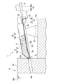
以下、本発明に係る閉塞開孔装置の第1実施形態を、図1から図6を参照しながら説明する。本閉塞開孔装置1は、図1に示すように高炉Wの炉壁W1に形成された出銑口W2を閉塞する閉塞モードと、図2に示すように閉塞された出銑口W2を開孔する開孔モードとに装置の状態を切り替えることができる。
図1に示すように、閉塞開孔装置1は、マッド材100が収容可能な内部空間11が形成されたケーシング10と、内部空間11に収容されたマッド材100に圧力を作用させる油圧発生部(圧力発生部)20と、出銑口W2を開孔するための開孔ロッド30と(図2参照。)、閉塞栓110などの基端に着脱可能に接続されるとともに閉塞栓110などを回転させる着脱・回転部(着脱部、回転駆動部)35と、着脱・回転部35を移動させる進退駆動部45とを備えている。
なお、開孔ロッド30および着脱・回転部35で、開孔機部を構成する。
(First embodiment)
Hereinafter, a first embodiment of a closed hole opening device according to the present invention will be described with reference to FIGS. 1 to 6. As shown in FIG. 1, the closed hole opening device 1 opens a closing mode for closing a tap outlet W2 formed in the furnace wall W1 of the blast furnace W, and a closed tap outlet W2 as shown in FIG. The state of the apparatus can be switched to a hole opening mode.
As shown in FIG. 1, the block opening device 1 includes a
The
ケーシング10は、先端側に配置され注入開口12aが形成されたノズル12と、基端側に配置され貫通孔13aが形成された略筒状のバレル13とを有している。注入開口12aおよび貫通孔13aは、ノズル12およびバレル13を接続したときに形成される内部空間11にそれぞれ連通する。
油圧発生部20は、ケーシング10の内部空間11における基端側に取り付けられている。油圧発生部20は、不図示の油供給源からオイルを供給される油圧シリンダ21と、油圧シリンダ21により前後方向に移動するピストン22とを有している。油圧シリンダ21には、油圧シリンダ21内のオイルの量を調節する不図示の流入口、および流出口が設けられている。
ピストン22の外周面と油圧シリンダ21の内周面との間には、ピストン22と油圧シリンダ21との間を水密に保持するための不図示のシール部材が設けられている。油圧シリンダ21によりピストン22が先端側に移動したときにおいても、ピストン22より前方に注入開口12aおよび貫通孔13aが配置されるように設定されている。本実施形態では、ピストン22が注入開口12aおよび貫通孔13aを塞がないので、ピストン22や油圧シリンダ21に閉塞栓110やマッド材100を通すための孔は形成されていない。
The
The
A seal member (not shown) is provided between the outer peripheral surface of the
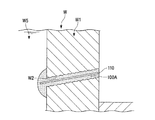
開孔ロッド30は、図2に示すように、細長い棒状に形成されている。開孔ロッド30の先端には、炉壁W1などを掘削するためのビット31が設けられている。開孔ロッド30の基端には、図3に示すような雌ネジ部32が形成されている。この例では、開孔ロッド30は、ケーシング10の外部に配置されて用いられる。
本実施形態の閉塞開孔装置1で用いられる閉塞栓110は、図1に示すように、マッド材100の焼成物(後述する焼成マッド材100A)よりも柔らかい焼成した耐火物により、略棒状に形成されている。閉塞栓110の長さは、出銑口W2の長さにほぼ等しく設定されている。閉塞栓110は、例えば、アルミナ、ろう石、炭化珪素、耐火粘土などからなるマッド材を焼成した耐火物により形成されている。閉塞栓110を柔らかくするには、例えば、マッド材中のバインダー(タール、レジン)の含有量を増やせばよく、閉塞栓110を硬くするには、マッド材中の金属(アルミニウムなど)の含有量を増やせばよい。
閉塞栓110の基端には、前述の開孔ロッド30の雌ネジ部32のような不図示の雌ネジ部が形成されている。
As shown in FIG. 2, the
As shown in FIG. 1, the
A female screw portion (not shown) such as the
着脱・回転部35は、着脱・回転機構36と、着脱・回転機構36に接続される着脱アダプタ37とを有している。
着脱・回転機構36は、図3に示す雄ネジ部38と、不図示の回転駆動モータとを備えている。この雄ネジ部38に開孔ロッド30の雌ネジ部32を螺合させることで、着脱・回転機構36に開孔ロッド30を接続することができる。回転駆動モータは、雄ネジ部38を雄ネジ部38の軸線C1回りに回転させる。これにより、着脱・回転機構36の雄ネジ部38に接続された開孔ロッド30は、自身の軸線回りに回転することができる。
着脱アダプタ37は、不図示のギアボックス、および連結軸39を有している。着脱・回転機構36に着脱アダプタ37を接続することで、着脱・回転機構36の雄ネジ部38にギアボックスが係合し、連結軸39をその軸線C2回りに回転させることができる。
連結軸39の先端には、閉塞栓110の雌ネジ部と螺合する不図示の雄ネジ部が形成されている。連結軸39の軸線C2と雄ネジ部38の軸線C1とは、ほぼ平行に設定されている。また、この例では、軸線C1は、注入開口12aおよび貫通孔13aより下方に配置されている。
The attachment / detachment /
The attachment / detachment /
The
A male screw portion (not shown) that is screwed with the female screw portion of the
ケーシング10の下部には、軸線C2方向に延びるガイドレール51、および位置調節装置52が取り付けられている。
進退駆動部45は、ガイドレール51上に設置されている進退駆動モータ45aと、ガイドレール51の下部に軸線C2方向にスライド可能に接続された進退駆動部本体45bとを有している。進退駆動モータ45aを駆動することで、進退駆動部本体45bをガイドレール51に沿って軸線C2方向に進退させることができる。
連結軸39の雄ネジ部に閉塞栓110を接続し、進退駆動部45により閉塞栓110を先端側に移動させることで、閉塞栓110を貫通孔13aおよび内部空間11を通して注入開口12aから前方へ突出させることができる。
位置調節装置52は床面W3上に配置され、床面W3に対するケーシング10の前後方向および上下方向の位置を調節することができる。
A
The advance /
The
The
図1に示す閉塞モードでは、図2に示す開孔モードよりケーシング10を下方に移動させて作業を行う。
開孔モードでは、貫通孔13aを塞ぐ栓部材53を用いてもよい。
In the closed mode shown in FIG. 1, the
In the opening mode, a
次に、以上のように構成された閉塞開孔装置1を用いて行われる本実施形態の閉塞開孔方法について説明する。以下では、説明の便宜上、図1に示すように、炉壁W1に出銑口W2が形成されていて、閉塞モードになっている閉塞開孔装置1で出銑口W2を閉塞する閉塞工程を行うことから説明する。この状態では、高炉W内の高温の溶銑W5が炉外側D1に流れ出ている。
まず、ケーシング10の貫通孔13aに閉塞栓110を挿通させる(閉塞栓配置工程)。具体的には、ガイドレール51上で進退駆動部45の進退駆動部本体45bを基端側に移動させておき、着脱・回転機構36に着脱アダプタ37を接続したうえで、連結軸39の先端に閉塞栓110を接続する。このとき、閉塞栓110を連結軸39の前方で保持しておき、着脱・回転機構36により閉塞栓110に対して連結軸39を軸線C2回りに回転させる。これにより、閉塞栓110の雌ネジ部と連結軸39の雄ネジ部とを螺合させ、連結軸39に閉塞栓110を容易に接続することができる。
そして、進退駆動部45により閉塞栓110を先端側に移動させ、閉塞栓110の先端が貫通孔13aを通過して注入開口12aにほぼ一致するように調節する。
Next, the closed hole opening method of this embodiment performed using the closed hole opening device 1 configured as described above will be described. In the following, for convenience of explanation, as shown in FIG. 1, as shown in FIG. 1, a closing process is performed in which the tap wall W <b> 2 is formed in the furnace wall W <b> 1 and the tap opening W <b> 2 is closed with the closing hole opening device 1 in the closing mode. I will explain from what to do. In this state, hot hot metal W5 in the blast furnace W flows out to the furnace outer side D1.
First, the blocking
Then, the closing
次に、炉壁W1の出銑口W2とケーシング10の注入開口12aとを連通させる(連通配置工程)。これは、位置調節装置52によりケーシング10の前後方向および上下方向の位置を調節することで行う。
続いて、油圧発生部20により、図4に示すように、マッド材100を注入開口12aを通して出銑口W2に押し出し、出銑口W2にマッド材100を充填させる(マッド材押し出し工程)。
Next, the tap hole W2 of the furnace wall W1 and the injection opening 12a of the
Subsequently, as shown in FIG. 4, the hydraulic
マッド材押し出し工程に続いて、図5に示すように、閉塞栓110を、ケーシング10の注入開口12aを通して出銑口W2に押し出す(閉塞栓押し出し工程)。
出銑口W2に押し出された閉塞栓110により、出銑口W2から押し出されたマッド材100が炉内側D2で凸の状態に盛り上がり、保護マッド101を形成する。保護マッド101は、出銑口W2から流れ出る溶銑W5によって炉壁W1が侵食されるのを保護する。
出銑口W2にケーシング10を当接させた状態で一定時間保持し、その後、位置調節装置52によりケーシング10を基端側に移動させ、出銑口W2からケーシング10を離間させる(焼成工程)。この工程の間に、溶銑W5の熱によりマッド材100が焼成され、図6に示す焼成マッド材100Aとなる。
以上で、閉塞工程を終了する。
Subsequent to the mud material pushing step, as shown in FIG. 5, the
Due to the
The
This is the end of the closing process.
この状態で高炉Wを一定時間運転し、再び溶銑W5を取り出すときに、以下に説明する開孔工程を行う。
開孔工程では、図2に示すように、着脱・回転機構36から着脱アダプタ37を取り外し、着脱・回転機構36に開孔ロッド30を接続する。
位置調節装置52によりケーシング10を上方に移動させ、出銑口W2を閉塞している閉塞栓110に開孔ロッド30のビット31を当接させる。着脱・回転機構36により開孔ロッド30を軸線C1回りに回転させつつ、進退駆動部45により開孔ロッド30を先端側に移動させることで、閉塞栓110、および閉塞栓110より炉内側D2にある焼成マッド材100Aを掘削して出銑口W2を形成する。
以上で、開孔工程を終了する。
In this state, when the blast furnace W is operated for a certain period of time and the hot metal W5 is taken out again, a hole forming step described below is performed.
In the opening step, as shown in FIG. 2, the attachment /
The
This completes the hole opening step.
以上説明したように、本実施形態の閉塞開孔装置1および閉塞開孔方法によれば、閉塞栓110は、焼成マッド材100Aよりも柔らかい耐火物で形成されている。このため、開孔工程において、この閉塞栓110を掘削して開孔することで開孔作業に要する力が低減し、出銑口W2を容易に開孔することができる。
また、焼成マッド材100Aは閉塞栓110より硬く、溶銑W5などにより侵食されにくいので、出銑口W2が溶銑W5により侵食されて大きくなるのを抑えることができる。
As described above, according to the closed hole opening device 1 and the closed hole opening method of the present embodiment, the
Further, the fired
閉塞栓110の長さは出銑口W2の長さにほぼ等しく設定されている。開孔工程に掘削する長さが閉塞栓110の長さにほぼ等しくなり開孔工程では柔らかい部材を掘削することになるため、出銑口W2をさらに容易に開孔することができる。
閉塞開孔装置1は、開孔ロッド30および着脱・回転部35を備えるため、閉塞モードと開孔モードとを切り替えることで、1台の装置で閉塞工程および開孔工程の両工程を行うことができる。
開孔工程において開孔ロッド30がケーシング10の外部に配置されるため、開孔ロッド30が溶銑W5の熱などにより曲がったとしても、閉塞開孔装置1の動作に支障となるのが防止される。
The length of the blocking
Since the blocking hole opening device 1 includes the
Since the opening
(第2実施形態)
次に、本発明の第2実施形態について図7から図10を参照しながら説明するが、前記実施形態と同一の部位には同一の符号を付してその説明は省略し、異なる点についてのみ説明する。
図7に示すように、本実施形態の閉塞開孔装置1で用いられる閉塞栓120は、外径が出銑口W2の内径より小さく設定されたパイプ(管状部材)121と、パイプ121の管路に配置された充填部材122とを有している。
パイプ121を形成する材料としては、たとえば、鉄鋼などの金属を用いることができる。充填部材122は、前述の閉塞栓110と同一の材料で形成されている。
なお、閉塞栓120の基端には、閉塞栓110の雌ネジ部と同一形状の雌ネジ部が形成されていることが好ましい。
(Second Embodiment)
Next, a second embodiment of the present invention will be described with reference to FIG. 7 to FIG. 10, but the same parts as those in the above-described embodiment will be denoted by the same reference numerals and the description thereof will be omitted, and only differences will be described. explain.
As shown in FIG. 7, the
As a material for forming the
In addition, it is preferable that a female screw portion having the same shape as the female screw portion of the blocking
次に、以上のように構成された閉塞栓120および閉塞開孔装置1を用いて行われる本実施形態の閉塞開孔方法について説明する。
閉塞工程は、閉塞栓110を用いて行う第1実施形態の工程と同様なので、説明を省略する。
開孔工程では、図8に示すように、出銑口W2を閉塞している閉塞栓120の充填部材122に開孔ロッド30のビット31を当接させる。そして、閉塞栓120の充填部材122、および充填部材122より炉内側D2にある焼成マッド材100Aを掘削して出銑口W2を形成する。
このように構成された閉塞栓120を用いる本実施形態の閉塞開孔方法によれば、焼成マッド材100Aよりも柔らかい充填部材122を掘削することで、出銑口W2を容易に開孔することができる。
Next, the block opening method of this embodiment performed using the
Since the closing process is the same as the process of the first embodiment performed using the
In the opening step, as shown in FIG. 8, the
According to the block opening method of the present embodiment using the
本実施形態のように、閉塞栓120において、焼成マッド材100Aよりも柔らかく形成されている部分を、閉塞栓120の全長にわたって連なるよう形成する。そして、開孔工程において、この柔らかく形成されている部分を閉塞栓120の全長にわたって開孔ロッド30で掘削することで、出銑口W2を容易に開孔することができる。
このため、第1実施形態の閉塞栓110のように、閉塞栓110全体が柔らかく形成されていてもよいし、閉塞栓の外周の一部が全長にわたって柔らかく形成されていてもよい。
As in the present embodiment, a portion of the
For this reason, like the
本実施形態では、閉塞栓120に代えて、図9に示す閉塞栓130を用いてもよい。
この閉塞栓130は、前述の閉塞栓120において、充填部材122が、パイプ121の一端121aから一定距離離間した位置Pよりパイプ121の他端121b側のみに配置されている。この一定距離は、閉塞開孔装置1におけるビット31の大きさなどに応じて適宜設定される。
パイプ121の一端121a側の内周面には、閉塞栓110の雌ネジ部と同一形状の雌ネジ部が形成されていることが好ましい。
In this embodiment, instead of the blocking
In the closing plug 130, the filling
A female screw portion having the same shape as the female screw portion of the
このように構成された変形例の閉塞栓130を用いて行われる閉塞開孔方法の閉塞工程は、本実施形態の閉塞工程と同様になる。一方で、開孔工程は以下のようになる。
図10に示すように、閉塞栓130のパイプ121の一端121a内に閉塞開孔装置1のビット31を挿入し、着脱・回転機構36により開孔ロッド30をその軸線回りに回転させる。これにより、充填部材122、および充填部材122より炉内側D2にある焼成マッド材100Aを掘削し、出銑口W2を形成する。
The closing process of the closing hole opening method performed using the closing plug 130 of the modified example configured as described above is the same as the closing process of the present embodiment. On the other hand, the opening process is as follows.
As shown in FIG. 10, the
本実施形態のように閉塞栓120を用いて閉塞された部分に出銑口W2を開孔するときには、炉外側D2の充填部材122に凹みが形成されるまでの間、開孔ロッド30の先端が回転ブレを起こすため、金棒などを使用して、作業者が開孔ロッド30の先端の位置を拘束している。
これに対して、本変形例の閉塞栓130を用いることで、閉塞栓130に対して開孔ロッド30の先端を容易に位置決めし、開孔ロッド30の回転ブレを抑えることができる。これにより、出銑口W2を短時間で形成することができる。
When the spout W2 is opened in the portion closed by using the
On the other hand, by using the closure plug 130 of this modification, the tip of the
以上、本発明の第1実施形態および第2実施形態について図面を参照して詳述したが、具体的な構成はこの実施形態に限られるものではなく、本発明の要旨を逸脱しない範囲の構成の変更なども含まれる。さらに、各実施形態で示した構成のそれぞれを適宜組み合わせて利用できることは、言うまでもない。
たとえば、前記第1実施形態および第2実施形態では、閉塞栓110、および閉塞栓120の充填部材122は、焼成マッド材100Aよりも柔らかい焼成した耐火物により形成されているとした。しかし、これらは、焼成されることで焼成マッド材100Aよりも柔らかい耐火物となる材料により形成さていてもよい。
この材料としては、前述のアルミナ、ろう石、炭化珪素、耐火粘土、および、これらの混合物を用いることができる。
閉塞栓110および充填部材122をこのような材料で形成することで、焼成された閉塞栓110または充填部材122を掘削して、出銑口W2を容易に開孔することができる。
As mentioned above, although 1st Embodiment and 2nd Embodiment of this invention were explained in full detail with reference to drawings, the concrete structure is not restricted to this embodiment, The structure of the range which does not deviate from the summary of this invention Changes are also included. Furthermore, it goes without saying that the configurations shown in the embodiments can be used in appropriate combinations.
For example, in the first embodiment and the second embodiment, the
As this material, the above-mentioned alumina, wax, silicon carbide, refractory clay, and a mixture thereof can be used.
By forming the
また、前記第1実施形態および第2実施形態では、図11に示すように、閉塞開孔装置2がケーシング10の内部空間11に設けられたガイド管61を備えてもよい。
ガイド管61の一端61aは、ケーシング10の注入開口12a内に注入開口12aを形成する縁部から離間した状態で配置されている。ガイド管61は、他端61b側の開口が貫通孔13aに連通するように配置されている。
ガイド管61の内径は、閉塞栓110が挿通可能となるように設定されている。
閉塞開孔装置2をこのように構成することで、閉塞モードにおいて、ケーシング10内で閉塞栓110とマッド材100とによる摩擦力が生じにくくなるため、出銑口W2に閉塞栓110を容易に挿入することができる。
In the first embodiment and the second embodiment, as shown in FIG. 11, the
One
The inner diameter of the
By configuring the
前記第1実施形態および第2実施形態では、開孔機部は開孔ロッド30および着脱・回転部35で構成され、閉塞開孔装置1に一体に構成されるとした。しかし、閉塞開孔装置に開孔機部を備えず、開孔機部として公知の錐ロッドなどを用いてもよい。
また、第1実施形態および第2実施形態では、閉塞栓の長さは出銑口W2の長さにほぼ等しく設定されているとした。しかし、閉塞栓の長さに制限はなく、出銑口W2の長さより短くするなど適宜設定することができる。
In the first embodiment and the second embodiment, the hole-opening machine part is configured by the hole-forming
In the first embodiment and the second embodiment, the length of the closing plug is set to be approximately equal to the length of the tap hole W2. However, the length of the obturator plug is not limited, and can be set as appropriate, for example, shorter than the length of the spout W2.
前記第1実施形態および第2実施形態の閉塞開孔装置1では、閉塞工程において出銑口W2に閉塞栓110を押し出さずに、出銑口W2をマッド材100だけで閉塞させることで、従来と同様の手法で出銑口W2を閉塞させることができる。すなわち、本発明の閉塞開孔装置1は、マッド材100および閉塞栓110を用いて出銑口W2を閉塞する方法と、マッド材100だけを用いて出銑口W2を閉塞する方法とを切り替えて使用することができる。
In the closing and opening device 1 of the first and second embodiments, the closing port W2 is closed only by the
1、2 閉塞開孔装置
10 ケーシング
11 内部空間
12a 注入開口
13a 貫通孔
20 油圧発生部(圧力発生部)
30 開孔ロッド
35 着脱・回転部(着脱部、回転駆動部)
45 進退駆動部
61 ガイド管
100 マッド材
110、120、130 閉塞栓
121 パイプ(管状部材)
122 充填部材
W 高炉
W1 炉壁
W2 出銑口
DESCRIPTION OF
30
45 Advance /
122 Filling member W Blast furnace W1 Furnace wall W2
Claims (9)
マッド材および略棒状に形成された閉塞栓を前記出銑口に押し出し、前記マッド材を焼成させて閉塞する閉塞工程と、
前記閉塞栓および焼成された前記マッド材を掘削して前記出銑口を形成する開孔工程と、
を備え、
前記閉塞栓は、前記マッド材の焼成物よりも柔らかく前記マッド材に押し込み可能に形成されている柔軟部分を、自身の全長にわたって連なるように有し、
前記閉塞工程は、
前記出銑口に前記マッド材を充填させる工程と、
前記マッド材が充填された前記出銑口に前記閉塞栓を押し込む工程と、を備えることを特徴とする閉塞開孔方法。 A closing hole opening method for closing the tap hole formed on the furnace wall of the blast furnace and opening the blocked tap hole,
A plugging step for extruding the plug material formed in the form of a mud material and a substantially rod to the outlet and firing and closing the mud material;
An opening step of excavating the plug and the fired mud material to form the tap hole;
With
The closing plug, a flexible portion formed so as to be pushed into the mud material softer than the firing of the mud material, possess so as to be continuous over the entire length of its own,
The closing step includes
Filling the mud material into the tap hole;
And a step of pushing the closing plug into the tap opening filled with the mud material .
管状部材と、
前記管状部材の管路に配置された前記柔軟部分である充填部材と、
を有することを特徴とする請求項1に記載の閉塞開孔方法。 The plug is
A tubular member;
A filling member which is the flexible portion disposed in a pipe line of the tubular member;
The closed hole opening method according to claim 1, comprising:
前記開孔工程では前記閉塞栓の前記充填部材を掘削することを特徴とする請求項3に記載の閉塞開孔方法。 The filling member is formed of a fired refractory,
The closed hole opening method according to claim 3 , wherein the filling member of the closed plug is excavated in the opening step.
前記開孔工程では前記閉塞栓の前記充填部材を掘削することを特徴とする請求項3に記載の閉塞開孔方法。 The filling member is formed of a material comprising a refractory between this being fired,
The closed hole opening method according to claim 3 , wherein the filling member of the closed plug is excavated in the opening step.
マッド材が収容可能な内部空間、前記内部空間に連通する注入開口および貫通孔が形成されたケーシングと、
前記内部空間に収容された前記マッド材に圧力を作用させる圧力発生部と、
略棒状に形成された閉塞栓の基端に着脱可能に接続されるとともに、前記出銑口を閉塞した前記閉塞栓および焼成された前記マッド材を掘削する開孔機部と、
前記開孔機部に接続された前記閉塞栓を、前記出銑口に前記マッド材を充填させた後で、前記貫通孔および前記内部空間を通して前記注入開口から突出させて前記出銑口に押し出すように移動させる進退駆動部と、
を備え、
前記閉塞栓は、前記マッド材の焼成物よりも柔らかく前記マッド材に押し込み可能に形成されている部分を、自身の全長にわたって連なるように有することを特徴とする閉塞開孔装置。 A closing and opening device for closing the tap opening formed on the furnace wall of the blast furnace and opening the closed tap opening,
An internal space in which the mud material can be accommodated, a casing in which an injection opening and a through hole communicating with the internal space are formed;
A pressure generating unit that applies pressure to the mud material accommodated in the internal space;
An opening machine part that is detachably connected to the proximal end of the closure plug formed in a substantially rod shape, and that excavates the closure plug and the fired mud material that has blocked the tap hole;
Said closure plug connected to the perforator unit, after is filled with the mud material into the taphole, push the taphole are protruded from the inlet opening through the through hole and the internal space An advancing / retreating drive unit that moves like
With
The closing plug has a portion that is formed so as to be softer than the fired product of the mud material and can be pushed into the mud material so as to be continuous over its entire length.
前記閉塞栓の基端に着脱可能に接続される着脱部と、
前記ケーシングの外部に配置されるとともに、前記着脱部に自身の基端が着脱可能に接続される開孔ロッドと、
前記着脱部に接続された前記開孔ロッドを前記開孔ロッドの軸線回りに回転させる回転駆動部とを有することを特徴とする請求項7に記載の閉塞開孔装置。 The opening machine part is
A detachable part detachably connected to the proximal end of the plug;
An opening rod that is disposed outside the casing and has a base end that is detachably connected to the detachable portion;
The closed opening device according to claim 7, further comprising: a rotation driving unit that rotates the opening rod connected to the attaching / detaching unit around an axis of the opening rod.
前記ガイド管内に前記閉塞栓が挿通可能に設定されていることを特徴とする請求項7または8に記載の閉塞開孔装置。 Provided in the inner space of the casing, the tip in the injection opening of the casing, is disposed in a state of being separated from at least some of the edges to form a pre-Symbol injection opening, said through opening on the base end side A guide pipe communicating with the hole,
9. The obturator opening device according to claim 7 or 8, wherein the obturator plug is set to be insertable into the guide tube.
Priority Applications (7)
| Application Number | Priority Date | Filing Date | Title |
|---|---|---|---|
| JP2011210737A JP5785838B2 (en) | 2011-09-27 | 2011-09-27 | Closed hole opening method and closed hole opening device |
| KR1020147008935A KR101593345B1 (en) | 2011-09-27 | 2012-09-25 | Blocking/opening method, blocking method and blocking/opening apparatus |
| IN2846DEN2014 IN2014DN02846A (en) | 2011-09-27 | 2012-09-25 | |
| CN201280046784.0A CN103890198B (en) | 2011-09-27 | 2012-09-25 | Inaccessible boring method, occlusive method and inaccessible boring device |
| BR112014007046-6A BR112014007046B1 (en) | 2011-09-27 | 2012-09-25 | LOCKING / OPENING METHOD FOR RACING HOLE AND LOCKING / OPENING APPARATUS |
| PCT/JP2012/074502 WO2013047490A1 (en) | 2011-09-27 | 2012-09-25 | Blocking/opening method, blocking method and blocking/opening apparatus |
| TW101135615A TWI493044B (en) | 2011-09-27 | 2012-09-27 | Taphole plugging/unplugging method and taphole plugging/unplugging apparatus |
Applications Claiming Priority (1)
| Application Number | Priority Date | Filing Date | Title |
|---|---|---|---|
| JP2011210737A JP5785838B2 (en) | 2011-09-27 | 2011-09-27 | Closed hole opening method and closed hole opening device |
Publications (2)
| Publication Number | Publication Date |
|---|---|
| JP2013072102A JP2013072102A (en) | 2013-04-22 |
| JP5785838B2 true JP5785838B2 (en) | 2015-09-30 |
Family
ID=47995522
Family Applications (1)
| Application Number | Title | Priority Date | Filing Date |
|---|---|---|---|
| JP2011210737A Active JP5785838B2 (en) | 2011-09-27 | 2011-09-27 | Closed hole opening method and closed hole opening device |
Country Status (7)
| Country | Link |
|---|---|
| JP (1) | JP5785838B2 (en) |
| KR (1) | KR101593345B1 (en) |
| CN (1) | CN103890198B (en) |
| BR (1) | BR112014007046B1 (en) |
| IN (1) | IN2014DN02846A (en) |
| TW (1) | TWI493044B (en) |
| WO (1) | WO2013047490A1 (en) |
Families Citing this family (5)
| Publication number | Priority date | Publication date | Assignee | Title |
|---|---|---|---|---|
| CN105319579B (en) * | 2014-06-26 | 2017-11-03 | 中石化石油工程地球物理有限公司胜利分公司 | Gunlock structure under mud gun epicenter drill gun one drilling type |
| CN104141021B (en) * | 2014-08-28 | 2015-11-11 | 中冶南方工程技术有限公司 | A kind of method of blast furnace open hole and blast furnace open hole device systems |
| WO2020182303A1 (en) * | 2019-03-13 | 2020-09-17 | Tmt Tapping Measuring Technology Sàrl | Taphole plugging gun |
| JP7146109B2 (en) * | 2019-03-13 | 2022-10-03 | ティエムティ - タッピング メジャーリング テクノロジー エスエイアールエル | tapped hole plug gun |
| TWI779501B (en) * | 2021-02-24 | 2022-10-01 | 中國鋼鐵股份有限公司 | Guiding device, guiding system and operation method thereof |
Family Cites Families (13)
| Publication number | Priority date | Publication date | Assignee | Title |
|---|---|---|---|---|
| JPS6126709A (en) * | 1984-07-17 | 1986-02-06 | Nippon Steel Corp | Closing method of tap hole |
| JPH0765087B2 (en) * | 1986-12-24 | 1995-07-12 | 川崎炉材株式会社 | Blast furnace tap hole closing method |
| JPS63166919A (en) * | 1986-12-27 | 1988-07-11 | Kawasaki Refract Co Ltd | Method for supplying mud material |
| JPH01127612A (en) | 1987-11-09 | 1989-05-19 | Kawasaki Steel Corp | Method for plugging iron tapping hole in blast furnace |
| DE3803132A1 (en) * | 1988-02-03 | 1989-08-17 | Dango & Dienenthal Maschbau | METHOD AND STOPPING CANNON FOR CLOSING THE OVEN STITCH HOLE |
| DE3803625A1 (en) * | 1988-02-06 | 1989-08-17 | Dango & Dienenthal Maschbau | METHOD AND DEVICE FOR OPENING THE STITCH HOLE OF OEFEN |
| ES2125929T3 (en) * | 1992-06-17 | 1999-03-16 | Wurth Paul Sa | MACHINE FOR DRILLING A PIQUERA FROM A CUBA OVEN. |
| LU88453A1 (en) * | 1994-01-17 | 1995-09-01 | Wurth Paul Sa | Tap hole plugging device |
| JPH0853703A (en) * | 1994-08-10 | 1996-02-27 | Nippon Steel Corp | Formation of iron tapping hole in blast furnace |
| JPH1046218A (en) * | 1996-08-05 | 1998-02-17 | Matsuda Astec Kk | Device for opening/closing residual iron flow-out hole |
| KR200168296Y1 (en) * | 1999-08-06 | 2000-02-15 | 삼성전자주식회사 | Printed circuit board |
| JP2002371308A (en) * | 2001-06-13 | 2002-12-26 | Sumitomo Metal Ind Ltd | Blast furnace tap-hole unit and operation controlling method therefor |
| JP2003247011A (en) * | 2002-02-20 | 2003-09-05 | Nippon Steel Corp | Method and device for opening/closing molten metal tapping hole for metallurgical furnace |
-
2011
- 2011-09-27 JP JP2011210737A patent/JP5785838B2/en active Active
-
2012
- 2012-09-25 CN CN201280046784.0A patent/CN103890198B/en active Active
- 2012-09-25 WO PCT/JP2012/074502 patent/WO2013047490A1/en active Application Filing
- 2012-09-25 IN IN2846DEN2014 patent/IN2014DN02846A/en unknown
- 2012-09-25 BR BR112014007046-6A patent/BR112014007046B1/en active IP Right Grant
- 2012-09-25 KR KR1020147008935A patent/KR101593345B1/en active IP Right Grant
- 2012-09-27 TW TW101135615A patent/TWI493044B/en not_active IP Right Cessation
Also Published As
| Publication number | Publication date |
|---|---|
| TWI493044B (en) | 2015-07-21 |
| WO2013047490A1 (en) | 2013-04-04 |
| KR20140066215A (en) | 2014-05-30 |
| IN2014DN02846A (en) | 2015-05-15 |
| CN103890198A (en) | 2014-06-25 |
| TW201326407A (en) | 2013-07-01 |
| BR112014007046B1 (en) | 2019-02-19 |
| KR101593345B1 (en) | 2016-02-11 |
| BR112014007046A2 (en) | 2017-04-11 |
| CN103890198B (en) | 2016-01-13 |
| JP2013072102A (en) | 2013-04-22 |
Similar Documents
| Publication | Publication Date | Title |
|---|---|---|
| JP5785838B2 (en) | Closed hole opening method and closed hole opening device | |
| CA2608050A1 (en) | Flow nozzle assembly | |
| US20130216312A1 (en) | Method, System And Rock Drilling Apparatus For Installing A Pipe In Drilled Holes In Rock Drilling | |
| ITTO20090593A1 (en) | SOIL DRILLING MACHINE. | |
| JP5771433B2 (en) | Closure structure of brewing opening and closing method of brewing opening | |
| JP6895929B2 (en) | Drilling equipment, rod-shaped members and drilling methods | |
| US10281213B2 (en) | Tap-hole refurbishing | |
| JPH01225712A (en) | Method and mud gun for closing tapping hole of furnace | |
| JP2013072103A (en) | Method for blocking tap hole | |
| DE3443143A1 (en) | METHOD AND DEVICE FOR OPENING AND CLOSING A STITCH HOLE ON OEFEN | |
| CN109877307A (en) | Self-locking inner tube port system | |
| JP2012219331A (en) | Hole opening and closing apparatus | |
| JP6521311B2 (en) | Chemical solution injection method under pressurized water | |
| JP4985027B2 (en) | Spout opening device and spout closing device | |
| JP7173684B2 (en) | How to build a rock bolt structure | |
| KR200224581Y1 (en) | Tap hole rising temperature of blast furnace control apparatus | |
| JP2015093993A (en) | Aperture block device and method | |
| JP2017150226A (en) | Hole drilling mouth device, hole drilling device and hole drilling method | |
| US298251A (en) | Chaeles a | |
| KR101203643B1 (en) | Removing apparatus for pin | |
| JPS58199807A (en) | Method for closing tap hole of blast furnace | |
| JP2003247011A (en) | Method and device for opening/closing molten metal tapping hole for metallurgical furnace | |
| KR101036913B1 (en) | Apparatus and methode for sealing gap of mudgun and nozzle tip | |
| JP2007205002A (en) | Cutter bit for shield machine, cutter bit loading tool, and cutter bit loading method | |
| KR200270813Y1 (en) | Tap hole scrap cutter structure of blast furnace |
Legal Events
| Date | Code | Title | Description |
|---|---|---|---|
| A621 | Written request for application examination |
Free format text: JAPANESE INTERMEDIATE CODE: A621 Effective date: 20140523 |
|
| A131 | Notification of reasons for refusal |
Free format text: JAPANESE INTERMEDIATE CODE: A131 Effective date: 20150421 |
|
| A521 | Request for written amendment filed |
Free format text: JAPANESE INTERMEDIATE CODE: A523 Effective date: 20150605 |
|
| TRDD | Decision of grant or rejection written | ||
| A01 | Written decision to grant a patent or to grant a registration (utility model) |
Free format text: JAPANESE INTERMEDIATE CODE: A01 Effective date: 20150630 |
|
| A61 | First payment of annual fees (during grant procedure) |
Free format text: JAPANESE INTERMEDIATE CODE: A61 Effective date: 20150727 |
|
| R150 | Certificate of patent or registration of utility model |
Ref document number: 5785838 Country of ref document: JP Free format text: JAPANESE INTERMEDIATE CODE: R150 |
|
| R250 | Receipt of annual fees |
Free format text: JAPANESE INTERMEDIATE CODE: R250 |
|
| S533 | Written request for registration of change of name |
Free format text: JAPANESE INTERMEDIATE CODE: R313533 |
|
| R350 | Written notification of registration of transfer |
Free format text: JAPANESE INTERMEDIATE CODE: R350 |
|
| R250 | Receipt of annual fees |
Free format text: JAPANESE INTERMEDIATE CODE: R250 |
|
| R250 | Receipt of annual fees |
Free format text: JAPANESE INTERMEDIATE CODE: R250 |
|
| R250 | Receipt of annual fees |
Free format text: JAPANESE INTERMEDIATE CODE: R250 |
|
| R250 | Receipt of annual fees |
Free format text: JAPANESE INTERMEDIATE CODE: R250 |
|
| R250 | Receipt of annual fees |
Free format text: JAPANESE INTERMEDIATE CODE: R250 |
|
| S111 | Request for change of ownership or part of ownership |
Free format text: JAPANESE INTERMEDIATE CODE: R313111 |
|
| R360 | Written notification for declining of transfer of rights |
Free format text: JAPANESE INTERMEDIATE CODE: R360 |
|
| R360 | Written notification for declining of transfer of rights |
Free format text: JAPANESE INTERMEDIATE CODE: R360 |
|
| R371 | Transfer withdrawn |
Free format text: JAPANESE INTERMEDIATE CODE: R371 |
|
| S111 | Request for change of ownership or part of ownership |
Free format text: JAPANESE INTERMEDIATE CODE: R313111 |
|
| R350 | Written notification of registration of transfer |
Free format text: JAPANESE INTERMEDIATE CODE: R350 |