JP5779028B2 - Light distribution control means for headlamp - Google Patents
Light distribution control means for headlamp Download PDFInfo
- Publication number
- JP5779028B2 JP5779028B2 JP2011163225A JP2011163225A JP5779028B2 JP 5779028 B2 JP5779028 B2 JP 5779028B2 JP 2011163225 A JP2011163225 A JP 2011163225A JP 2011163225 A JP2011163225 A JP 2011163225A JP 5779028 B2 JP5779028 B2 JP 5779028B2
- Authority
- JP
- Japan
- Prior art keywords
- vehicle
- light distribution
- oncoming vehicle
- light
- oncoming
- Prior art date
- Legal status (The legal status is an assumption and is not a legal conclusion. Google has not performed a legal analysis and makes no representation as to the accuracy of the status listed.)
- Expired - Fee Related
Links
Images


Classifications
-
- B—PERFORMING OPERATIONS; TRANSPORTING
- B60—VEHICLES IN GENERAL
- B60Q—ARRANGEMENT OF SIGNALLING OR LIGHTING DEVICES, THE MOUNTING OR SUPPORTING THEREOF OR CIRCUITS THEREFOR, FOR VEHICLES IN GENERAL
- B60Q1/00—Arrangement of optical signalling or lighting devices, the mounting or supporting thereof or circuits therefor
- B60Q1/02—Arrangement of optical signalling or lighting devices, the mounting or supporting thereof or circuits therefor the devices being primarily intended to illuminate the way ahead or to illuminate other areas of way or environments
- B60Q1/04—Arrangement of optical signalling or lighting devices, the mounting or supporting thereof or circuits therefor the devices being primarily intended to illuminate the way ahead or to illuminate other areas of way or environments the devices being headlights
- B60Q1/14—Arrangement of optical signalling or lighting devices, the mounting or supporting thereof or circuits therefor the devices being primarily intended to illuminate the way ahead or to illuminate other areas of way or environments the devices being headlights having dimming means
- B60Q1/1415—Dimming circuits
- B60Q1/1423—Automatic dimming circuits, i.e. switching between high beam and low beam due to change of ambient light or light level in road traffic
- B60Q1/143—Automatic dimming circuits, i.e. switching between high beam and low beam due to change of ambient light or light level in road traffic combined with another condition, e.g. using vehicle recognition from camera images or activation of wipers
-
- F—MECHANICAL ENGINEERING; LIGHTING; HEATING; WEAPONS; BLASTING
- F21—LIGHTING
- F21S—NON-PORTABLE LIGHTING DEVICES; SYSTEMS THEREOF; VEHICLE LIGHTING DEVICES SPECIALLY ADAPTED FOR VEHICLE EXTERIORS
- F21S41/00—Illuminating devices specially adapted for vehicle exteriors, e.g. headlamps
- F21S41/10—Illuminating devices specially adapted for vehicle exteriors, e.g. headlamps characterised by the light source
- F21S41/14—Illuminating devices specially adapted for vehicle exteriors, e.g. headlamps characterised by the light source characterised by the type of light source
- F21S41/141—Light emitting diodes [LED]
- F21S41/143—Light emitting diodes [LED] the main emission direction of the LED being parallel to the optical axis of the illuminating device
-
- F—MECHANICAL ENGINEERING; LIGHTING; HEATING; WEAPONS; BLASTING
- F21—LIGHTING
- F21S—NON-PORTABLE LIGHTING DEVICES; SYSTEMS THEREOF; VEHICLE LIGHTING DEVICES SPECIALLY ADAPTED FOR VEHICLE EXTERIORS
- F21S41/00—Illuminating devices specially adapted for vehicle exteriors, e.g. headlamps
- F21S41/10—Illuminating devices specially adapted for vehicle exteriors, e.g. headlamps characterised by the light source
- F21S41/14—Illuminating devices specially adapted for vehicle exteriors, e.g. headlamps characterised by the light source characterised by the type of light source
- F21S41/141—Light emitting diodes [LED]
- F21S41/147—Light emitting diodes [LED] the main emission direction of the LED being angled to the optical axis of the illuminating device
- F21S41/148—Light emitting diodes [LED] the main emission direction of the LED being angled to the optical axis of the illuminating device the main emission direction of the LED being perpendicular to the optical axis
-
- F—MECHANICAL ENGINEERING; LIGHTING; HEATING; WEAPONS; BLASTING
- F21—LIGHTING
- F21S—NON-PORTABLE LIGHTING DEVICES; SYSTEMS THEREOF; VEHICLE LIGHTING DEVICES SPECIALLY ADAPTED FOR VEHICLE EXTERIORS
- F21S41/00—Illuminating devices specially adapted for vehicle exteriors, e.g. headlamps
- F21S41/60—Illuminating devices specially adapted for vehicle exteriors, e.g. headlamps characterised by a variable light distribution
- F21S41/63—Illuminating devices specially adapted for vehicle exteriors, e.g. headlamps characterised by a variable light distribution by acting on refractors, filters or transparent cover plates
- F21S41/64—Illuminating devices specially adapted for vehicle exteriors, e.g. headlamps characterised by a variable light distribution by acting on refractors, filters or transparent cover plates by changing their light transmissivity, e.g. by liquid crystal or electrochromic devices
- F21S41/645—Illuminating devices specially adapted for vehicle exteriors, e.g. headlamps characterised by a variable light distribution by acting on refractors, filters or transparent cover plates by changing their light transmissivity, e.g. by liquid crystal or electrochromic devices by electro-optic means, e.g. liquid crystal or electrochromic devices
-
- F—MECHANICAL ENGINEERING; LIGHTING; HEATING; WEAPONS; BLASTING
- F21—LIGHTING
- F21S—NON-PORTABLE LIGHTING DEVICES; SYSTEMS THEREOF; VEHICLE LIGHTING DEVICES SPECIALLY ADAPTED FOR VEHICLE EXTERIORS
- F21S41/00—Illuminating devices specially adapted for vehicle exteriors, e.g. headlamps
- F21S41/60—Illuminating devices specially adapted for vehicle exteriors, e.g. headlamps characterised by a variable light distribution
- F21S41/65—Illuminating devices specially adapted for vehicle exteriors, e.g. headlamps characterised by a variable light distribution by acting on light sources
- F21S41/657—Illuminating devices specially adapted for vehicle exteriors, e.g. headlamps characterised by a variable light distribution by acting on light sources by moving light sources
-
- F—MECHANICAL ENGINEERING; LIGHTING; HEATING; WEAPONS; BLASTING
- F21—LIGHTING
- F21S—NON-PORTABLE LIGHTING DEVICES; SYSTEMS THEREOF; VEHICLE LIGHTING DEVICES SPECIALLY ADAPTED FOR VEHICLE EXTERIORS
- F21S41/00—Illuminating devices specially adapted for vehicle exteriors, e.g. headlamps
- F21S41/60—Illuminating devices specially adapted for vehicle exteriors, e.g. headlamps characterised by a variable light distribution
- F21S41/67—Illuminating devices specially adapted for vehicle exteriors, e.g. headlamps characterised by a variable light distribution by acting on reflectors
- F21S41/675—Illuminating devices specially adapted for vehicle exteriors, e.g. headlamps characterised by a variable light distribution by acting on reflectors by moving reflectors
-
- B—PERFORMING OPERATIONS; TRANSPORTING
- B60—VEHICLES IN GENERAL
- B60Q—ARRANGEMENT OF SIGNALLING OR LIGHTING DEVICES, THE MOUNTING OR SUPPORTING THEREOF OR CIRCUITS THEREFOR, FOR VEHICLES IN GENERAL
- B60Q2300/00—Indexing codes for automatically adjustable headlamps or automatically dimmable headlamps
- B60Q2300/05—Special features for controlling or switching of the light beam
- B60Q2300/056—Special anti-blinding beams, e.g. a standard beam is chopped or moved in order not to blind
-
- B—PERFORMING OPERATIONS; TRANSPORTING
- B60—VEHICLES IN GENERAL
- B60Q—ARRANGEMENT OF SIGNALLING OR LIGHTING DEVICES, THE MOUNTING OR SUPPORTING THEREOF OR CIRCUITS THEREFOR, FOR VEHICLES IN GENERAL
- B60Q2300/00—Indexing codes for automatically adjustable headlamps or automatically dimmable headlamps
- B60Q2300/40—Indexing codes relating to other road users or special conditions
- B60Q2300/41—Indexing codes relating to other road users or special conditions preceding vehicle
-
- B—PERFORMING OPERATIONS; TRANSPORTING
- B60—VEHICLES IN GENERAL
- B60Q—ARRANGEMENT OF SIGNALLING OR LIGHTING DEVICES, THE MOUNTING OR SUPPORTING THEREOF OR CIRCUITS THEREFOR, FOR VEHICLES IN GENERAL
- B60Q2300/00—Indexing codes for automatically adjustable headlamps or automatically dimmable headlamps
- B60Q2300/40—Indexing codes relating to other road users or special conditions
- B60Q2300/42—Indexing codes relating to other road users or special conditions oncoming vehicle
-
- B—PERFORMING OPERATIONS; TRANSPORTING
- B60—VEHICLES IN GENERAL
- B60Q—ARRANGEMENT OF SIGNALLING OR LIGHTING DEVICES, THE MOUNTING OR SUPPORTING THEREOF OR CIRCUITS THEREFOR, FOR VEHICLES IN GENERAL
- B60Q2300/00—Indexing codes for automatically adjustable headlamps or automatically dimmable headlamps
- B60Q2300/40—Indexing codes relating to other road users or special conditions
- B60Q2300/45—Special conditions, e.g. pedestrians, road signs or potential dangers
Landscapes
- Engineering & Computer Science (AREA)
- General Engineering & Computer Science (AREA)
- Physics & Mathematics (AREA)
- Microelectronics & Electronic Packaging (AREA)
- Optics & Photonics (AREA)
- Mechanical Engineering (AREA)
- Chemical & Material Sciences (AREA)
- Crystallography & Structural Chemistry (AREA)
- Lighting Device Outwards From Vehicle And Optical Signal (AREA)
Description
本発明は、車両用前照灯の配光を制御して異なる配光パターンを生成する配光制御手段に関する。 The present invention relates to a light distribution control means for controlling the light distribution of a vehicle headlamp to generate different light distribution patterns.
対向車線を有する道路上を車で走行する際には、通常は前照灯を下向きに照射するロービームにより走行し、必要に応じて、例えば、夜間など前方遠側に、より視界が必要な場合に、前照灯を上向きに照射するハイビームにより走行するのが一般的である。
しかしながら、ハイビームによって対向車線側のカットオフラインよりも上側の領域にビームを照射した場合には、すれ違う際に対向車両の運転者にグレア(眩惑)を与えて視認を妨げてしまうという問題がある。
このグレアの問題を解決するため、近年、自動車のヘッドランプの配光制御システムとして、すれ違い時に対向車両の運転者に眩惑を与えないように、対向車両に照射されるビームを遮光することが可能なADB(Adaptive Driving Beam)と呼ばれる技術、更にその変形として液晶素子やMEMS素子、LEDアレイを使用して、車両前方のスクリーン上の領域(ゾーン)毎に配光を制御するAZB(Adaptive Zone Beaming)と呼ばれる技術が提案されている。
When driving on a road that has an opposite lane, you usually drive with a low beam that illuminates the headlight downward, and if necessary, for example, when you need more visibility on the far side, such as at night In general, the vehicle travels with a high beam that irradiates the headlamp upward.
However, when a high beam irradiates a region above the cutoff line on the opposite lane side, there is a problem in that when passing each other, glare (dazzling) is given to the driver of the oncoming vehicle, thereby hindering visual recognition.
To solve this glare problem, as a light distribution control system for automobile headlamps in recent years, it is possible to block the beam irradiated to the oncoming vehicle so as not to dazzle the driver of the oncoming vehicle when passing each other AZB (Adaptive Zone Beaming) that controls the light distribution for each area (zone) on the screen in front of the vehicle using a technology called ADB (Adaptive Driving Beam) and, as a modification, a liquid crystal element, a MEMS element, and an LED array ) Has been proposed.
例えば、特許文献1(特開2009−218155号公報)には、水平方向に一列に設けられた複数の発光素子を備えて、各発光素子の発光の有無や光量を制御することにより多様な配光パターンを形成可能な車両用前照灯装置が開示されている。
かかる車両用前照灯装置は、運転者が確認しにくくなる車両前方の領域の発生を抑制しつつ、前走車や歩行者に与える眩惑(グレア)を抑制するために、車両に搭載したカメラ等により撮像した画像データに基づいて対向車の位置を特定し、対向車が存在すると推定される車両前方領域の位置を遮光し、或いは光量を低下させるように発光素子を制御している。
これによれば、すれ違い時においてもロービームに切り替えることなく対向車へのグレアを防止できるため、夜間においてもロービームを上回る路面照射性能を維持したまま走行することができ、特に対向車線側の路肩に存在する歩行者や小動物の視認性において高い効果を発揮している。
For example, Patent Document 1 (Japanese Patent Application Laid-Open No. 2009-218155) includes a plurality of light emitting elements arranged in a row in the horizontal direction, and controls the presence / absence of light emission and the amount of light of each light emitting element in various ways. A vehicle headlamp device capable of forming a light pattern is disclosed.
Such a vehicle headlamp device is a camera mounted on a vehicle in order to suppress the occurrence of a region in front of the vehicle that is difficult for the driver to check, and to suppress glare given to a preceding vehicle or a pedestrian. The position of the oncoming vehicle is specified based on the image data captured by the above, and the light emitting element is controlled so as to block the position of the vehicle front area where the oncoming vehicle is estimated to exist or to reduce the amount of light.
According to this, since glare to the oncoming vehicle can be prevented without switching to the low beam even when passing each other, it is possible to travel while maintaining the road surface illumination performance exceeding the low beam even at night, especially on the shoulder on the opposite lane side. It is highly effective in the visibility of existing pedestrians and small animals.
しかしながら、特許文献1に記載されているような従来の配光制御には、以下のような問題点があった。
従来のADB技術では、ハイビームで走行中に対向車両とすれ違う際、対向車両を照射するビームを遮光している場合でも、対向車両の外側路面を照明するようになっていることから、自車両と対向車両との間に位置する対向車両側の路肩で横断を待機している歩行者を視認することができる点で有利であると考えられる。
しかしその一方で、運転者は、歩行者の膝下を視認できれば歩行者を認識できるため、歩行者が道路を横断しない状態では、対向車両側の歩道待機者(歩行者)の全身(カットオフラインよりも上側)を照射することに本来的な意味は無い。また、運転者の視野の範囲を幅広く照明することにより運転者の注視範囲を広げることができる一方で、注視範囲が広がると、広い範囲からの情報を得られる一方で、その他の場所、特に最も注視すべき自車線側前方における視認距離を低下させる虞がある。
更に、自車両と対向車との間の相対距離(車頭時間:(すれ違いまでの時間距離))がある一定の範囲内に留まる場合には、対向車線側の路肩にいる歩行者M2(図16参照)の横断行動については必ずしも考慮せずに済む場合がある。
However, the conventional light distribution control as described in
In the conventional ADB technology, when passing the oncoming vehicle while traveling with a high beam, even if the beam irradiating the oncoming vehicle is shielded, the outer road surface of the oncoming vehicle is illuminated. It is considered that it is advantageous in that a pedestrian waiting for crossing can be visually recognized on the shoulder of the oncoming vehicle located between the oncoming vehicle.
However, on the other hand, the driver can recognize the pedestrian if he / she can visually recognize the pedestrian's knees. Therefore, when the pedestrian does not cross the road, the whole body of the sidewalk waiter (pedestrian) on the oncoming vehicle side (from the cut-off line) There is no intrinsic meaning in irradiating the upper side. In addition, the driver's field of view can be broadened by broadly illuminating the driver's field of view, while widening the area of gaze gives information from a wide range, while other places, especially the most There is a risk of reducing the viewing distance in front of the own lane to watch.
Further, when the relative distance between the host vehicle and the oncoming vehicle (vehicle head time: (time distance to passing each other)) remains within a certain range, the pedestrian M2 on the shoulder on the opposite lane side (FIG. 16). There is a case where it is not always necessary to consider the crossing behavior of (see).
図16は、自車両と対向車両とのすれ違い時における歩行者の横断行動を説明するための路面照射イメージを示す図である。
図17は、図16に対応した上記のAZB技術における自車両前方のスクリーンを示す図である。
図16において、車線幅3.5mの片側一車線道路を、自車両Cと対向車両Aがともに車速60km/hで走行しており、自車両Cと対向車両Aとの車頭時間が10秒(約170m)の位置に存在する状態が示されている。
また、図16に示す道路において、路肩200(センターラインCLより5m)には、横断待機者M1、M2や小動物(不図示)が存在している。
このような道路状況で、道路を横断しようとしている歩行者M2の歩行速度が5km/h(1.4m/s)である場合、道路の全幅10mを渡りきるのに約7秒を要する。
更に、渡りきるまでの余裕時間(リスク回避時間)を3秒必要とすれば、歩行者M2が道路を横断しようと判断するタイミングとしては、歩行者M2の遠方側の車線202に存在する車両(図では自車両C)に対しては約10秒が必要となる。
FIG. 16 is a diagram illustrating a road surface irradiation image for explaining a pedestrian's crossing behavior when the host vehicle and the oncoming vehicle pass each other.
FIG. 17 is a diagram showing a screen in front of the host vehicle in the AZB technique corresponding to FIG.
In FIG. 16, the host vehicle C and the oncoming vehicle A are both traveling at a vehicle speed of 60 km / h on a one-lane road with a lane width of 3.5 m, and the head time of the host vehicle C and the oncoming vehicle A is 10 seconds ( The state which exists in the position of about 170 m) is shown.
In the road shown in FIG. 16, there are crossing waiting persons M1 and M2 and small animals (not shown) on the shoulder 200 (5 m from the center line CL).
In such a road condition, when the walking speed of the pedestrian M2 trying to cross the road is 5 km / h (1.4 m / s), it takes about 7 seconds to cross the entire width of 10 m.
Furthermore, if a margin time (risk avoidance time) of 3 seconds is required for crossing, the time when the pedestrian M2 determines to cross the road is the vehicle (in the
一方、歩行者M2側の車線201に存在する車両(図16では、対向車両A)に対しては、歩行者M2がセンターラインCLを超えるまでに要する3秒に加え、余裕時間をやや少ない2秒と仮定すれば、歩行者M2がセンターラインCLを超えるまでに約5秒必要となる。
従って、歩行者から見て左右両方向に自分に向かってくる車両が存在する場合(対向車両A、自車両C)に、車頭時間が15秒以下であると、歩行者は、横断することが不可能と判断して道路の横断行動に移らないと考えられる。上記のように、自車両Cと対向車両Aとの車頭時間は10秒となっており、15秒以下であるから、小動物の飛び出しこそ考えられるものの、歩行者M2は横断行動に移らないと考えられる。
On the other hand, for the vehicle existing in the
Therefore, when there is a vehicle that is facing you in both the left and right directions when viewed from the pedestrian (oncoming vehicle A and host vehicle C), if the vehicle head time is 15 seconds or less, the pedestrian cannot cross. Judging that it is possible, it is thought that it will not move to crossing the road. As described above, the head time of the host vehicle C and the oncoming vehicle A is 10 seconds, which is 15 seconds or less. Therefore, although a small animal can be expected to jump out, the pedestrian M2 does not move to the crossing action. It is done.
以上の状況を考慮すると、自車両Cと対向車両Aとの距離がある一定の範囲にある場合、対向車線201側におけるロービームのカットオフラインよりも上側の領域(図17に示すAZBの第1象限)への光束は、第4象限(自車線202の遠側領域)に向けるか、或いは、第2象限、第3象限(ロービームのカットオフラインよりも下方)における自車線側の歩行者M1や道路線形の確認に利用することが望ましい。
In consideration of the above situation, when the distance between the host vehicle C and the oncoming vehicle A is within a certain range, the region above the low beam cutoff line on the
小動物については、視認はできても回避は困難であるものの、路面(第2象限、第3象限)への照射光量を向上させて少しでも視認性の改善を図る必要はある。
もっとも、車頭時間が十分に大きい時(対向車両が図17のHV近傍に存在する場合)に第1象限(図17)の光量の減少させるとすれば、対向車線201側の歩行者の視認性が低下し、却って危険である。
例えば、自車両C・対向車両Bともに車速60km/hで走行しているとして、車頭時間が30秒の場合、車頭距離は約1000mとなるが、この場合には、グレア(眩惑)を与えないために図17における対向車両A部分(ハッチング部)203のビームのみを遮光(グレアを抑制)することになるが、自車両と対向車両との車頭時間が十分に長く、歩行待機者が横断してくることが予想される状況では対向車両側の(第1象限の)横断待機者を照射する必要がある。
本発明は、上記事情に鑑みてなされたものであり、前方への配光を制御して対向車両へのビームをマスクすることにより対向車両の運転者に眩惑を与えないようにするとともに、自車両と対向車両との間の距離に応じて、対向車両の路肩側への配光をも制御して、より重要な領域を運転者に注視させることが可能なヘッドランプの配光制御手段を提供することを目的とする。
Although small animals can be visually recognized but difficult to avoid, it is necessary to improve the visibility by improving the amount of light applied to the road surface (second quadrant, third quadrant).
Of course, if the amount of light in the first quadrant (FIG. 17) is reduced when the vehicle head time is sufficiently long (when the oncoming vehicle is present in the vicinity of HV in FIG. 17), the visibility of the pedestrian on the
For example, assuming that the host vehicle C and the oncoming vehicle B are both traveling at a vehicle speed of 60 km / h and the vehicle head time is 30 seconds, the vehicle head distance is about 1000 m. In this case, no glare is given. Therefore, only the beam of the oncoming vehicle A portion (hatched portion) 203 in FIG. 17 is shielded (glare is suppressed), but the head time between the own vehicle and the oncoming vehicle is sufficiently long, and the walking standby person crosses. In a situation that is expected to come, it is necessary to irradiate a crossing waiting person (in the first quadrant) on the oncoming vehicle side.
The present invention has been made in view of the above circumstances, and controls the light distribution forward to mask the beam to the oncoming vehicle so as not to dazzle the driver of the oncoming vehicle. According to the distance between the vehicle and the oncoming vehicle, a light distribution control means for the headlamp that can also control the light distribution on the shoulder side of the oncoming vehicle and allow the driver to watch a more important area. The purpose is to provide.
上記の課題を鑑みて、請求項1の発明は、対向車両と自車両との相対距離に応じて前記対向車両に眩惑を与えないように照射制限された配光パターンを照射させるヘッドランプの配光制御手段であって、前記ヘッドランプは、マトリクス状に配設され、光源から出射された光の反射光量を制御することにより前記自車両前方の領域毎に光量制御が可能な光学素子を備え、前記配光制御手段は、前記相対距離が第1所定値以上では、前記対向車両の領域が照射制限されると共に、少なくとも前記対向車両よりも対向車線側が照射される配光パターンを照射させるように前記光学素子を制御し、前記相対距離が、前記第1所定値未満かつ前記第2所定値以上では、前記対向車両の領域及び前記対向車両よりも対向車線側への光を自車線側に配光し、前記対向車両の領域及び前記対向車両よりも対向車線側が照射制限された配光パターンを照射させるように前記光学素子を制御し、前記相対距離が、前記第2所定値未満では、前記対向車両に対する照射制限が解除された配光パターンを照射させるように前記光学素子を制御することを特徴とする。
In view of the above problems, the invention of
上記のように構成したので、本発明によれば、前方への配光を制御して対向車両へのビームをマスクすることにより対向車両の運転者に眩惑を与えないようにするとともに、自車両と対向車両との間の距離に応じて、対向車両よりも路肩側への配光も制御して、より重要な領域を運転者に注視させることができる。 Since it comprised as mentioned above, according to this invention, while controlling the light distribution ahead and masking the beam to an oncoming vehicle, it does not give a dazzling to the driver of an oncoming vehicle, and the own vehicle Depending on the distance between the oncoming vehicle and the oncoming vehicle, the light distribution toward the shoulder side of the oncoming vehicle can also be controlled so that the driver can watch a more important area.
以下に、図面を参照して本発明の実施の形態例を詳細に説明する。
[第1の実施形態]
(車載用前照灯ユニットの構成)
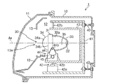
図1は、本発明の第1の実施形態に係る配光制御システムに適用可能な車載用前照灯ユニット1(以下、前照灯ユニットと記す)の構成例を説明する図である。図2は、図1に示すA−A線における前照灯ユニットの断面図である。
なお、以下に説明する前照灯ユニット1の構成はあくまで一例に過ぎず、後述のランプユニットの駆動機構などは、他の構成を採用しても良いことは言うまでもない。
本実施形態に係る前照灯ユニット1は、図1に示すように、ランプボディ10と透光カバー(カバー)11で形成された灯室12内に、主配光(メインビーム)の光量を確保可能なメインランプユニット20と、例えばLED(Light Emission Diode)等の半導体発光素子等を光源として配光パターンを可変形成可能なプロジェクタ型のサブランプユニット30と、を備えている。
Embodiments of the present invention will be described below in detail with reference to the drawings.
[First Embodiment]
(Configuration of on-vehicle headlamp unit)
FIG. 1 is a diagram illustrating a configuration example of an in-vehicle headlamp unit 1 (hereinafter referred to as a headlamp unit) applicable to the light distribution control system according to the first embodiment of the present invention. 2 is a cross-sectional view of the headlamp unit taken along line AA shown in FIG.
It should be noted that the configuration of the
As shown in FIG. 1, the
また、メインランプユニット20、サブランプユニット30と、カバー11との間には、灯具前方から見た際の隙間を覆うように、エクステンション13が配置されている。このエクステンション13には、メインランプユニット20、サブランプユニット30をその前端部近傍において露出させている開口部13aが形成されている。
メインランプユニット20、サブランプユニット30は、何れも車両前後方向に延びる光軸Axを有しており、図2に示すように、エイミング機構40を介して上下方向及び左右方向に傾動可能にランプボディ10に支持されている。
すなわち、ランプボディ10には、エイミング機構40を介して支持部材41が固定され、支持部材41には、サブランプユニット30の照射方向を左右方向に変更するメカ式駆動装置である左右変更機構(ACT:アクチュエータ)42が固定されている。
An
Each of the
That is, a
左右変更機構42は、駆動源42aがスイブル回動軸42bを中心に鉛直軸周りにユニット搭載部材43を揺動回転するスイブル機構である。
支持部材41の水平部に設けられた左右変更機構42の駆動源42aの出力軸には、スイブル回動軸42bが連結されており、駆動源42aが駆動されて出力軸が回転することで、ユニット搭載部材43がスイブル回転軸42bを中心に回転駆動される。
更に、ユニット搭載部材43には、サブランプユニット30の照射方向を上下方向に変更する上下変更機構(アクチュエータ)44が固定されている。
上下変更機構44は、駆動源44aがユニット上下回転軸44bを中心に水平軸周りでベース部材を上下方向にレベリング駆動できるレベリング機構である。
ユニット搭載部材43の水平部分に設けられた駆動源44aの出力軸にはピニオンギア45が固定されており、ピニオンギア45は、ユニット上下回転軸44bに固定された扇形ギア46に噛合されている。
駆動源44aが駆動されて出力軸が回転されると、ピニオンギア45及び扇型ギア46を介してユニット上下回転軸44bが回転されることで、ベース部材31がユニット上下回転軸44bを中心として揺動回転させられる。
The left / right changing
The
Further, an up / down changing mechanism (actuator) 44 that changes the irradiation direction of the
The up / down changing
A
When the
また、サブランプユニット30は、光源としての半導体発光素子(以下、光源と記載する)32と、リフレクタ(反射鏡)33と、投影レンズ34と、を備えている。
リフレクタ33は、光源32から出射された光を前方へ向けて光軸Ax寄りに反射させる反射面33aを有している。この反射面33aは、略楕円状の断面形状を有しており、その離心率は、鉛直断面から水平断面に向けて徐々に大きくなるように設定されている。これによって、反射面33aで反射した光源32からの光を、鉛直断面内においては投影レンズ34の後方側焦点F近傍に略集束させる。
投影レンズ34は、前方側表面34aが凸曲面状で、後方側表面34bが平面の平凸レンズとして構成されており、光軸Ax上に配置されている。そして、この投影レンズ34は、その後方側焦点Fを含む焦点面上の像を反転像として前方へ投影する。
投影レンズ34の前方側焦点34aを構成する凸曲面は、投影レンズ34の後方側焦点Fを光軸Ax上に位置させるように構成された非球面で構成されている。
The
The
The
The convex curved surface constituting the front
また、本実施形態におけるサブランプユニット30は、光源32から投影レンズ34の間の光路上の上記焦点F近傍に、光源32から出射された光束の光量を制御して本発明に特徴的な付加配光パターンを形成して、上述のAZBを実現するマトリックス状の配光制御素子(光制御電子部材)35を更に備えている。
なお、メインランプユニット20も、配光制御素子35を除いては、サブランプユニット30と同様の構成を備えており、車両の進行方向に合わせて上下変更機構、左右変更機構により光の照射方向を変更可能である。
Further, the
The
(配光制御素子の構成)
図3及び図4は、配光制御素子を備えた本実施形態のサブランプユニットを説明する図である。
なお、本実施形態のサブランプユニット30では、前方車両の有無、或いは存在位置に応じて配光パターンを変化させるADB(Adaptive Driving Beam)の中でも、特に、MEMS(Micro Electro Mechanical Systems:微小電気機械素子)方式(図3)や液晶方式(図4)を用いて、前方スクリーン上のゾーン毎に光量制御/配光制御を行って配光パターンを変化させることが可能な技術を採用していることは上記した通りである。
図3に示すMEMS素子35aは、マトリックス状に配置された各光学素子の光軸に対する角度を可変することにより、光源32からのビームの反射光量を制御する素子であり、また、図4に示す液晶素子35bは、マトリックス状に配置された各液晶素子(光制御箇所)における光源32からのビームの透過光量を制御する素子である。
これらの光量制御素子35を配光制御素子として使用することで、投影レンズ34から出射する光束の光量を制御して異なる付加配光パターンを形成することができる。
また、自車両前方の対向車両が存在する領域のビームを遮光/減光して対向車両へのグレアを防ぐという処理が可能であることもAZBの特徴となっている。
(Configuration of light distribution control element)
3 and 4 are diagrams for explaining the sub lamp unit of this embodiment provided with a light distribution control element.
In the
The
By using these light
Another feature of AZB is that it is possible to perform processing of blocking or dimming a beam in a region where an oncoming vehicle in front of the host vehicle is present to prevent glare to the oncoming vehicle.
(配光制御システムの構成)
図5は、本実施形態の車載用前照灯装置を制御して異なる配光パターンを形成する配光制御システムの機能構成を説明するブロック図である。
本実施形態の配光制御システムは、車両の適所に搭載された車載カメラ52により取得した撮像データについて画像処理を行い、車両に搭載された各種の既存の視界支援システム(ADB、プリクラッシュセーフティーシステム(衝突事故防止システム)、LDWS(Lane Departure Warning System:車線維持支援システム)など)に必要なデータを算出し、車内LANなどを介して各種の車載機器に発信する視界支援システムECU51と、この視界支援システムECU51から送出されてくる路上光輝物体の属性(対向車、先行車、反射器、道路照明)、その位置(前方、側方)と、車速センサ53から得た車速を基にその走行場面に対応した配光を決定し、その配光を実現するために必要な配光可変ランプ(サブランプユニット30)の駆動制御量(上下・左右ビーム移動量、遮光部分の位置と範囲、その制御と復帰など)を決定すると共に、図2で説明した具体的な実現手段であるアクチュエーター(ACT;メカ式駆動装置)42、44や配光制御素子35の制御量・制御内容を決定する本発明に特徴的な配光制御ECU(配光制御手段)50と、を備えている。
(Configuration of light distribution control system)
FIG. 5 is a block diagram illustrating a functional configuration of a light distribution control system that controls the in-vehicle headlamp device according to the present embodiment to form different light distribution patterns.
The light distribution control system of the present embodiment performs image processing on imaging data acquired by an in-
配光制御ECU50及び視界支援システムECU51は、各種の演算処理を実行するCPU(Central Processing Unit)と、各種の制御プログラムを格納するROM(Read Only Memory)、制御プログラムやデータを展開しCPUの処理のためのワークエリアとして機能するRAM(Random Access Memory)などを備えている。
車載カメラ52は、CCD(Charge Coupled Device:電荷結合素子)やCMOS(Complementary Metal Oxide Semiconductor:相補性金属酸化膜半導体)などを用いた電子光学カメラである。また、これらを複数使用したステレオ(複眼)カメラでも良い。
車載カメラ52により取得された撮像データは、視界支援システムECU51により処理解析される。
車速センサ53は、自車両の車速データを、車内LANを介して各種の車載機器に発信するセンサである。
更に、図5のシステムは、レーダ54、舵角センサ又はGPSナビ55、HLスイッチ56を備えている。
レーダ54は、レーザレーダやミリ波レーダであり、反射物体(対向車両)からの反射波の到達時間を計測することにより対向車両との車頭距離(相対距離)を計測する。
The light
The in-
Imaging data acquired by the in-
The
Furthermore, the system of FIG. 5 includes a
The
また、計測した車頭距離の時間的な変化と、車速センサ53により得られる自車両の車速データに基づいて対向車両との相対的な車速を計測することができる。
舵角センサ又はGPSナビ55は、曲路走行判定やカーブの曲率の計測などを行うセンサである。舵角センサはハンドルの回転角度のセンサであり、GPSナビは、カーナビゲーションの地図データから同様の計測を行う。これらの装置を組み合わせて用いても良い。これらの装置から得られる情報は各種車載機器に発信される。
既存のADB技術において、配光制御ECU50は、これらの装置から得られる情報を基に、配光可変ランプとしてのサブランプユニット30の水平方向の照射方向をカーブに合わせて左右にスイブルする。
HLスイッチ56は、ヘッドライトのOn/Offやビームの制御モード(ADBのOn/Offなど)を、車内LANなどを介して各種車載機器に発信する。
すなわち、H−H線(カットオフライン)以下に拡散配光を有する配光非可変のメインランプユニット20による固定ビーム(ロービーム)を、HLスイッチのON命令によって点灯させる。
また、サブランプユニット30は、AUTOビームSWやハイビームSWに連動して前方車両の存在状況や曲路などで配光が制御される。
ドライバ57は、配光制御ECU50からの制御量・制御内容を、ACT42、44や配光制御素子35の動作に対応した命令に変換すると共にそれらを制御する。
Further, the relative vehicle speed with respect to the oncoming vehicle can be measured based on the temporal change in the measured vehicle head distance and the vehicle speed data of the host vehicle obtained by the
The rudder angle sensor or
In the existing ADB technology, the light
The
That is, the fixed beam (low beam) by the non-light distribution
The
The driver 57 converts the control amount and control content from the light
(視界支援システムECUによる撮像データ処理)
視界支援システムECU51は、車載カメラ52による撮像データを以下のように処理・解析する。
(1)まず、車載カメラ52により取得された画像データについて画像処理や解析を行うことによりLM(レーンマーク;区画線)を検出すると共に、前方視野の各種対象物の輝度を検出する。
(2)次に、検出したレーンマークの情報を基に道路の線形や車線数を求めると共に、光輝物体の色情報(カラーカメラの場合)や光輝物体の属性(ヘッドランプの白色光(対向車)/テイルランプの赤色光(先行車))やその発光面積、そしてその路上位置情報を算出してRAMに記憶する。
(3)更に、撮像画像のフレーム間の光輝物体の位置、OF(オプティカルフロー)量などのデータを基に光輝物体の属性(対向車両、先行車両、道路付属施設の反射器など)や対向車両の車速などを決定する。なお、車載カメラ52が単眼カメラの場合には距離の検出精度が低いが、ステレオカメラとすることで精度を向上させることが可能である。
更に、車載カメラ52が単眼カメラである場合には距離の検出精度が低いので、これを補うために車間距離レーダ54により得られる距離情報を補填することが望ましい。
(Image data processing by vision support system ECU)
The visual field
(1) First, image processing and analysis are performed on the image data acquired by the in-
(2) Next, the road alignment and the number of lanes are obtained based on the detected lane mark information, and the color information of the bright object (in the case of a color camera) and the attribute of the bright object (white light of the headlamp (oncoming vehicle) ) / Red light of the tail lamp (preceding vehicle)), its light emitting area, and its road position information are calculated and stored in the RAM.
(3) Further, attributes of the bright object (oncoming vehicle, preceding vehicle, reflector of road attached facility, etc.) and oncoming vehicle based on data such as the position of the bright object between frames of the captured image and the amount of optical flow (OF) Determine the vehicle speed. In addition, when the vehicle-mounted
Furthermore, since the distance detection accuracy is low when the in-
図6は、本実施形態の配光制御システムの処理の流れを説明するフローチャートである。
視界支援システムECU51は、上記した車載カメラ52、車速センサ53等から、前方視野画像データ、自車両の車速等のデータを取得する(ステップS101)。
次いで、視界支援システムECU51は、車載カメラ52から取得した画像データに基づいて、対向車両の検出処理を行う(ステップS102)。この処理には、対向車両の位置、対向車両の車速、自車両との相対距離等の演算も含まれる。
配光制御ECU50は、上述のAUTOビームSWやハイビームSWによってADB/Hiビーム/Lowビームの何れのビームが選択されているかを判断し(ステップS103)、ADBがONになっていれば(ステップS104でYes)、ステップS102で得られた対向車両の情報に基づいて配光制御の内容(サブランプユニット30の駆動方向、駆動量)を決定する(ステップS105)。
そして、配光制御ECU50は、決定した配光制御の内容をドライバ57用のデータに変換する処理を行い(ステップS106)、更に、配光制御素子35を駆動して本発明の配光制御を実行する(ステップS107)。
なお、ADBがONになっていなければ(ステップS104でNo)、設定結果に従って、Hiビーム、Lowビームとなるように、ランプユニットを制御する(ステップS108)。
FIG. 6 is a flowchart for explaining the processing flow of the light distribution control system of this embodiment.
The visual field
Next, the visual field
The light
Then, the light
If the ADB is not ON (No in step S104), the lamp unit is controlled so as to be a Hi beam and a Low beam according to the setting result (step S108).
視界支援システムECU51による画像解析処理について、図7を用いて更に詳述する。
図7は、直線路上に存在する物体のスクリーン上における模式図であり、日本等の国で実施されている左側通行の場合を例示している。
直線路では無限遠点の物体は消失点位置(スクリーン上のHV点)と一致し、有限距離の物体はこの消失点から放射状に存在する。
直線路では、対向車両のヘッドライト(白色光)60は水平線(H−H線)より下方、第4象限における対向車線61内に存在する。
自車線における前方車両のテールライト(赤色光)62はH−H線より下方(第3象限及び第4象限)の自車線63内に存在する。
ガードレールに取り付けられるデリニエーター(反射器)(白色光或いは橙色光)64はH−H線近傍に存在する。
The image analysis processing by the visual field
FIG. 7 is a schematic diagram on the screen of an object existing on a straight road, and illustrates the case of left-hand traffic implemented in countries such as Japan.
On a straight road, an object at an infinite point coincides with the vanishing point position (HV point on the screen), and an object at a finite distance exists radially from the vanishing point.
On the straight road, the headlight (white light) 60 of the oncoming vehicle is present in the oncoming
The tail light (red light) 62 of the front vehicle in the own lane is present in the
A delineator (reflector) (white light or orange light) 64 attached to the guardrail exists in the vicinity of the HH line.
また、道路照明装置(白色光又は淡黄色光)65はH−H線より上方の領域に存在する。
走行中、スクリーン上の移動物体はHV点から延びる放射線上を移動することとなる。従って走行中に前方路面を車載カメラ52により連続撮影した場合、路上物体のフレーム間の移動量(OF;オプティカルフローと呼ぶ)は遠方物体では小さく、近距離の物体は大きくなる。
図5についても述べたが、路上物体の属性(ヘッドランプか、テイルランプか、或いは道路照明であるか)は光輝物体の色光や輝度(明るさ)、またはOF量を基に判定することができる。
なお、図7において自車線、対向車線に付した符号63、61は、以下の説明で使用する図面においても引き続き用いるものとする。
Further, the road illumination device (white light or light yellow light) 65 exists in a region above the HH line.
During traveling, the moving object on the screen moves on the radiation extending from the HV point. Therefore, when the front road surface is continuously photographed by the in-
As described with reference to FIG. 5, the attribute of the road object (whether it is a headlamp, tail lamp, or road illumination) is determined based on the color light, luminance (brightness), or OF amount of the bright object. it can.
In addition, the code |
図8は、車両前方のスクリーン上の対向車両の位置とサイズとの関係を示す図である。なお、本図はランプを視点として作成されたものであり、図7と同様に左側通行の場合を例示している。
一車線の幅を3.5m、運転者の眼の位置を地上高1.5m、3.5m右とし、ヘッドランプの地上高を0.7mとした場合における自車線(追越車線)とその両側車線(走行車線、対向車線)および対向車両の運転者の眼の位置の軌跡を示している。
図中、符号70〜74が付された矩形は、車両前方のスクリーン上における対向車両の正面サイズを表し、矩形70〜74を貫く線分75が対向車両の運転者の眼の位置の軌跡を表している。
なお、歩行者M1、M2が自車線側、対向車線側における約50m先の路肩に存在している。
FIG. 8 is a diagram showing the relationship between the position and size of the oncoming vehicle on the screen in front of the vehicle. This figure is created with the lamp as the viewpoint, and illustrates the case of left-hand traffic as in FIG.
The own lane (overtaking lane) when the width of one lane is 3.5m, the driver's eye position is 1.5m above the ground, 3.5m right, and the headlamp is 0.7m above ground. The locus | trajectory of the driver | operator's eye position of a both-sides lane (traveling lane, oncoming lane) and an oncoming vehicle is shown.
In the figure, the rectangles denoted by
In addition, pedestrians M1 and M2 exist on the road shoulder about 50 m ahead on the own lane side and the opposite lane side.
図8は、自車線のセンターにセンサを設置した際のスクリーンを示しており、座標系における1マスは0.5°である。
かかる幾何配置において、自車両および対向車両の車速を各々60km/hとした場合、自車両との車頭時間が夫々20秒、10秒、5秒、2秒、1.5秒となる相対距離の地点に存在する対向車両のスクリーン上のサイズ及び運転者の眼の位置(地上高1.2m)は、以下のようになる。
なお、車両の正面サイズは鉛直(V−V線)方向1.5m、水平(H−H線)方向W2.0mである。
車頭時間が20秒(相対距離は約660m)の場合、矩形70で表される対向車両のスクリーン上の視角サイズは、V(鉛直方向)0.13°×H(水平方向)0.17°/U0.04°R0.30°となる。
車頭時間が10秒(相対距離は約330m)の場合、矩形71で表される対向車両のスクリーン上の視角サイズは、V0.26°×H0.35°/U0.08°R0.6 となる。
車頭時間5秒(相対距離は約165m)の場合、矩形72で表される対向車両の視角サイズは、V0.52°×H0.69°/U0.17°R1.22°である。
FIG. 8 shows a screen when the sensor is installed at the center of the own lane, and one square in the coordinate system is 0.5 °.
In such a geometric arrangement, when the vehicle speeds of the host vehicle and the oncoming vehicle are each 60 km / h, the relative distance at which the head time with the host vehicle is 20 seconds, 10 seconds, 5 seconds, 2 seconds, and 1.5 seconds, respectively. The size on the screen of the oncoming vehicle existing at the point and the position of the driver's eyes (1.2 m above the ground) are as follows.
The front size of the vehicle is 1.5 m in the vertical (V-V) direction and W 2.0 m in the horizontal (H-H) direction.
When the vehicle head time is 20 seconds (relative distance is about 660 m), the viewing angle size on the screen of the oncoming vehicle represented by the
When the vehicle head time is 10 seconds (relative distance is about 330 m), the viewing angle size on the screen of the oncoming vehicle represented by the
When the vehicle head time is 5 seconds (relative distance is about 165 m), the viewing angle size of the oncoming vehicle represented by the
また、車頭時間が2秒(相対距離が約66m)の場合、矩形73で表される対向車両の視角サイズはV1.30°×H1.74°/U0.43°R3.04°である。
更に、車頭時間が1.5秒(相対距離は約50m)の場合、対向車両の視角サイズは、V1.71°×H2.29°/U0.57°R4.00°である。
このような道路上における対向車両の存在状況において、車頭時間が5秒以上前方の対向車(矩形70、71)は視角サイズで0.5°以下(20秒の車頭時間では0.2°)と非常に小さく、HV点に近接している。
そして、車頭時間が5秒を切った近距離では、対向車の視覚サイズは急激に大きくなると共にHV点から離れることが分かる。従って、車頭距離、相対車速が既知であれば、車頭時間(相対距離)により遮光サイズを変更する必要がある。
また、図7についても述べたが、OF(オプティカルフロー)は遠方車両では小さく、近距離の車両では大きい。
従って、車載カメラ52の分解能にもよるが、遠方の対向車両はOFが小さいため、対向車両の判別は難しく、遠方に存在する対向車両と道路照明65(図7)、路肩反射器(デリニエーター)64(図7)との判別も難しい。
When the vehicle head time is 2 seconds (relative distance is about 66 m), the viewing angle size of the oncoming vehicle represented by the rectangle 73 is V1.30 ° × H1.74 ° / U0.43 ° R3.04 °.
Furthermore, when the vehicle head time is 1.5 seconds (relative distance is about 50 m), the viewing angle size of the oncoming vehicle is V1.71 ° × H2.29 ° / U0.57 ° R4.00 °.
In such a situation of oncoming vehicles on the road, the oncoming vehicles (
It can be seen that at a short distance where the vehicle head time is less than 5 seconds, the visual size of the oncoming vehicle increases rapidly and moves away from the HV point. Therefore, if the vehicle head distance and the relative vehicle speed are known, it is necessary to change the light shielding size according to the vehicle head time (relative distance).
Although described with reference to FIG. 7, OF (optical flow) is small in a distant vehicle and large in a short-distance vehicle.
Therefore, although it depends on the resolution of the in-
領域76は、対向車両の存在時に光量を向上すべき領域である。対向車の存在時において、対向車線側に存在する歩行者や小動物の視認に重要な範囲は自車両の前方20m(2°)〜80m(0.5°)としている。
自車両が60km/hで走行している場合において相対距離20mは1.2秒先であり、視対象物を視認して回避できるほぼ限界の時間である。
80mは約5秒先であり、この距離の視対象物が視認できるのであれば、60km/hでの走行上、十分に安全である。
なお、この領域76は、メインランプユニット20による固定配光(ヘッドランプSW−ONで常時点灯するベースビームで現状のロービームにほぼ相当)によって主に照射されるべき領域でもある。
それに対し、図8における領域77は、対向車両との車頭時間の変化に応じて光量を改善すべき範囲である。
80mより前方位置を照明するためにはこの領域(H−H線上方を含めたH−H線近傍部分)77を照明する必要がある。この領域77は対向車両の後方から横断してくる歩行者などの視認に重要である。従って、対向車両の位置変化に連動して照明範囲を対向車線側に拡大することが重要となる。
The
When the host vehicle is traveling at 60 km / h, the
80 m is about 5 seconds away, and if the object to be viewed at this distance can be visually recognized, it is sufficiently safe for traveling at 60 km / h.
This
On the other hand, a
In order to illuminate the front position from 80 m, it is necessary to illuminate this region (a portion near the HH line including the upper part of the HH line) 77. This
図9は、本実施形態の配光制御システムにおける配光の例を示す図である。
図9(a)は、メインビームユニット(固定配光ランプ)20によるロービーム形態のベースビーム80を示しており、これは、ヘッドライトON時に常時点灯するランプである。
適切な光学系(図示せず)により現状のロービームと同様に水平線(H−H線)よりも下方にビームを拡散させたベース配光を形成する。先行車両や対向車両など、視界前方の車両が多い場合や、自車両の車速が徐行レベルの場合、或いは前方車両だけではなく店舗照明や道路照明などが混在することでセンサ(車載カメラ)による車両の検出が不能、或いは信頼性が低い場合には、この固定ビームのみで走行するのが望ましい。
ベースビーム80は、水平線(H−H線)の近傍に明暗の境界線を有しており、対向車線側における水平線よりも上方の光を抑制しているので、この固定配光のみでは対向車両(の運転者)に対してグレア(眩惑)を与えることはない。
FIG. 9 is a diagram illustrating an example of light distribution in the light distribution control system of the present embodiment.
FIG. 9A shows a
A suitable light system (not shown) forms a base light distribution in which the beam is diffused below the horizontal line (H-H line) in the same manner as the current low beam. Vehicles with sensors (on-board cameras) when there are many vehicles in front of the field of view, such as preceding vehicles and oncoming vehicles, or when the vehicle speed of the host vehicle is at a slow speed level, or store lighting and road lighting are mixed in addition to the preceding vehicles When it is impossible to detect or the reliability is low, it is desirable to travel only with this fixed beam.
The
図9(b)は、本実施形態のサブランプユニット(可変配光ランプ)30による付加ビームとしての全面マトリックスビーム81を示している。
また、図9(c)は、(a)のベースビーム70と(b)の全面マトリックスビーム81とを合成した本実施形態の走行用ビーム82を示している。
本実施形態では、すれ違い時には、図9(c)に示す合成した走行用ビーム82に含まれる図9(b)の付加ビーム(付加配光パターン)の成分を制御することで、走行用ビーム82において遮光/減光を行い、対向車両におけるグレアを防止した配光パターンを形成する。
なお、これはセンサ(車載カメラ)による車両の検出能力が十分な場合には行うことが可能であり、不十分な場合にはメインランプユニット20による固定ビームのみで走行することになる。
FIG. 9B shows a full
FIG. 9C shows a traveling
In the present embodiment, at the time of passing, the traveling
This can be performed when the vehicle detection capability of the sensor (vehicle camera) is sufficient, and when it is insufficient, the vehicle travels only with a fixed beam by the
(対向車両の遮光サイズ)
本マトリックスビームでは対向車両部分のみ遮光或いは減光するが、対向車両の遮光サイズについては、基本的には1対のペアライト(ヘッドランプ)を包含する範囲を遮光する制御を行う。
ヘッドランプの取り付け間隔は車両サイズによるが、一般的に1.6m〜2.0mであり、車頭距離にもよるが、これを包含する1.2〜1.5倍程度が適当と考えられる。
遠距離の場合には、対向車位置の測定精度や処理時間誤差、路面の凹凸や加減速による車両の上下動(0.2〜0.5度)、電子制御素子のセグメント像サイズを考慮すると視角サイズで最低でも1.0度程度が最小遮光サイズとなる。鉛直方向も同等のサイズを遮光範囲とする。
先行車両についても同様の考え方で遮光すれば良い。
(Shading size of oncoming vehicle)
In this matrix beam, only the oncoming vehicle part is shielded or dimmed, but the oncoming vehicle shade size is basically controlled to shield the range including a pair of pair lights (headlamps).
Although the headlamp mounting interval depends on the vehicle size, it is generally 1.6 m to 2.0 m, and depending on the vehicle head distance, it is considered appropriate to be about 1.2 to 1.5 times including this.
In the case of a long distance, considering the oncoming vehicle position measurement accuracy, processing time error, road surface unevenness, acceleration / deceleration of the vehicle (0.2-0.5 degrees), and segment image size of the electronic control element The minimum light-shielding size is about 1.0 degree at least in the viewing angle size. The same size in the vertical direction is set as the light shielding range.
The preceding vehicle may be shielded from light in the same way.
また、後に詳述するが、対向車両を検知した瞬間や対向車両との車頭時間が第1の車頭時間以上の時には対向車両部分のみを遮光する。
また、対向車両が第2の車頭時間未満となり、最も近接した場合にはビームを初期状態(対向車無し;遮光無しの状態)に復帰させる。
対向車両の近接状態が第1の車頭時間と第2の車頭時間との間である場合は、第2の車頭時間の位置にいる対向車両の側方位置を照明限界とする(対向車両の対向車線側を照明しない)と共に、第2の車頭時間の位置よりも遠方に存在する対向車両を遮光する。
第2の車頭時間の対向車両の上方、或いは側方に向かう光束は減光するか自車線側に向けるように制御する。
なお、夜間における歩行者や車間距離の検出性能は、車速が高くなるに従って不正確になる。そこで車速が増加するのに伴い、対向車両を検知して遮光を開始する第1の車頭時間を短時間に設定できるようにする。第2の車頭時間についても同様である。
このようにADBの配光を車頭時間、或いは車間距離のファクタで制御すれば、対向車両へのグレアを抑制しながら、視認に必要な箇所を有効に照明できる。
なお、第1、第2の車間距離、或いは車頭時間は、車速により調整する。例えば、車速の増大に伴い、減少させるように調整する。
As will be described in detail later, only the oncoming vehicle portion is shielded from light when the oncoming vehicle is detected or when the head time of the oncoming vehicle is equal to or longer than the first head time.
When the oncoming vehicle is less than the second head time and comes closest, the beam is returned to the initial state (no oncoming vehicle; no light blocking state).
When the proximity state of the oncoming vehicle is between the first head time and the second head time, the side position of the oncoming vehicle at the position of the second head time is set as the lighting limit (the oncoming vehicle The lane side is not illuminated), and the oncoming vehicle located farther away than the position of the second head time is shielded.
Control is performed so that the light flux directed toward the upper side or the side of the oncoming vehicle at the second head time is dimmed or directed toward the own lane.
Note that the detection performance of pedestrians and inter-vehicle distances at night becomes inaccurate as the vehicle speed increases. Therefore, as the vehicle speed increases, the first vehicle head time for detecting the oncoming vehicle and starting the light shielding can be set in a short time. The same applies to the second vehicle head time.
Thus, by controlling the ADB light distribution by the factor of the vehicle head time or the inter-vehicle distance, it is possible to effectively illuminate a place necessary for visual recognition while suppressing glare to the oncoming vehicle.
The first and second inter-vehicle distances or the vehicle head time are adjusted by the vehicle speed. For example, the vehicle speed is adjusted to decrease as the vehicle speed increases.
第1、第2の車頭時間の具体的な値について説明する。
図8について述べたように、自車両と対向車両が共に車速60km/hですれ違う場合、車頭時間が10秒以上であると対向車両はHV点から0.5°と近接し、視角サイズも0.5°以下と非常に小さい。このような極小サイズの条件下では対向車両の判別は難しくなると共にその他の光輝物との判別も難しくなり、車頭時間が10秒以上では精細に制御することが難しくなる。そこで車載カメラによる検出上の問題をも考慮し、第1の車頭時間(相対距離の第1所定値に対応)は5秒とし、第2の車頭時間(相対距離の第2所定値に対応)は1.0秒とする。
Specific values of the first and second vehicle head times will be described.
As described with reference to FIG. 8, when both the host vehicle and the oncoming vehicle pass each other at a vehicle speed of 60 km / h, if the head time is 10 seconds or more, the oncoming vehicle is close to 0.5 ° from the HV point and the viewing angle size is also 0. Very small, less than 5 °. Under such an extremely small size condition, it is difficult to discriminate the oncoming vehicle, and it is difficult to discriminate it from other bright objects, and it becomes difficult to control precisely when the vehicle head time is 10 seconds or more. Therefore, in consideration of detection problems with the on-vehicle camera, the first vehicle head time (corresponding to the first predetermined value of the relative distance) is set to 5 seconds, and the second vehicle head time (corresponding to the second predetermined value of the relative distance). Is 1.0 seconds.
図10は、本実施形態における配光制御の例を示す図であり、対向車両との距離が変化するのに伴い、遮光を含む合成配光パターン82が変化していくことを表している。
図10では、直線路において、対向車線を複数台の対向車両(対向車両A、対向車両B)が走行している場合の例を示している。
(a)は、いずれの対向車両も第1所定値以上の相対距離に存在する場合の遮光の例である。上記のように、第1所定値の相対距離は車頭時間にして5秒とする。
(a)において、対向車両Aは自車両から5秒、対向車両Bは自車両から10秒の位置に存在する。従って、双方の対向車両も、自車両との相対距離が第1所定値以上の場所を走行していることになる。
この場合、配光制御ECU50は、対向車両A、Bに対して個別に遮光を行うように配光制御素子35を制御する。
遮光を行う領域は、検出された対向車位置を中心に、それぞれ±0.5°の範囲の領域90A、90Bである。これにより、対向車両A、Bへのグレアを低減し、安全性を向上させることができる。
FIG. 10 is a diagram illustrating an example of light distribution control in the present embodiment, and illustrates that the combined
FIG. 10 shows an example in which a plurality of oncoming vehicles (an oncoming vehicle A and an oncoming vehicle B) are traveling in an oncoming lane on a straight road.
(A) is an example of light shielding when any oncoming vehicle is present at a relative distance greater than or equal to the first predetermined value. As described above, the relative distance of the first predetermined value is 5 seconds as the vehicle head time.
In (a), the oncoming vehicle A exists at a position 5 seconds from the own vehicle, and the oncoming vehicle B exists at a
In this case, the light
The areas to be shielded are
(b)は、対向車両A、Bが、第2所定値以上の相対距離に存在する場合の遮光の例を示している。上記のように第2所定値は、車頭時間にして1秒とする。
(b)において、対向車両Aは自車両との車頭時間が2秒の位置に、対向車両Bは自車両との車頭時間が5秒の位置に存在する。従って、対向車両Aは、自車両との相対距離にして第2所定値以上、第1所定値未満の場所を走行していることになる。
この場合、配光制御ECU50は、対向車両Aについては、ほぼ対向車両Aのサイズ全体に跨る領域92を遮光し、自車両との車頭時間が5秒の場所にいる対向車両Bについては、(a)の場合と同様に、±0.5°の範囲の領域90Bを遮光するように、配光制御素子35を制御する。
(b)における対向車両Aのように、車頭時間が2秒となるような距離にまで自車両に近接すると、その遮光サイズは拡大し(対向車両のサイズとなる)、そのような対向車両の外側を照明する意味がなくなる。
(B) shows an example of light shielding when the oncoming vehicles A and B are present at a relative distance equal to or greater than the second predetermined value. As described above, the second predetermined value is 1 second as the vehicle head time.
In (b), the oncoming vehicle A exists at a position where the head time with the own vehicle is 2 seconds, and the oncoming vehicle B exists at a position where the head time with the own vehicle is 5 seconds. Therefore, the oncoming vehicle A is traveling in a location that is not less than the second predetermined value and less than the first predetermined value as a relative distance to the host vehicle.
In this case, for the oncoming vehicle A, the light
As the oncoming vehicle A in (b), when the vehicle head comes close to a distance such that the head time is 2 seconds, the shading size increases (becomes the size of the oncoming vehicle). It makes no sense to illuminate the outside.
そこで、配光制御ECU50は、最も近接している対向車両Aの遮光すべき範囲91とその外側領域92の光束を自車線側に移動(配光)させ(対向車両Aの領域と対向車線Aよりも対向車線側の領域を照射制限し)、自車線63の路面を照明するようにする(これは配光制御素子35としてMEMS素子を用いた場合のみ。液晶を用いる場合は、減光のみが可能である)。
上記のように配光制御素子35としてMEMS素子(光束を再配光)を用いた場合では、自車線の視認性が向上する。
液晶では、対向車両Aの遮光すべき範囲91とその外側領域92は減光のみとなり、照明しても対向車両のグレアにより本質的に視認できない。しかしながら、無意味に照明されている範囲が減ることにより、運転者は無意識に自車線を注視するようになり、自車線上に存在する歩行者や障害物の視認性を向上させることができる。
Therefore, the light
As described above, when a MEMS element (redistributed light flux) is used as the light
In the liquid crystal, the
(c)は、最近接している対向車両Aが第2の所定値未満の相対距離に離脱した場合の遮光例を示す図である。
対向車両が車頭距離1秒よりも近距離に接近するとスクリーン上の位置はHV点よりかなり離れ、ヘッドランプの照射光量は低下すると共に照射時間が少なくなるため、グレアの問題はなくなる。
最近接の対向車両が、この第2の所定値の相対距離に到達した直後に、サブランプユニット30を制御して近接車両に対する遮光を停止する(対向車無しの配光に復帰させる)。このようにすることで、すれ違い後に復帰させる場合に比べ路上の歩行者などの検出時間が早められる。
そして対向車両が車頭時間で1.0秒(30m)の距離にある場合のように、十分近距離に接近した場合には、グレア露光は短時間であり安全上の問題もないため、対向車両の遮光を停止する。
対向車両が車頭時間が1秒になるまで近接した場合、車間距離は約17mであり、これはヘッドランプより約6°側方位置となりグレア光量は低くなる。
(C) is a figure which shows the light-shielding example in case the oncoming vehicle A which adjoined most has left | separated to the relative distance of less than 2nd predetermined value.
When the oncoming vehicle approaches a shorter distance than the vehicle head distance of 1 second, the position on the screen is far away from the HV point, the amount of light emitted from the headlamp is reduced, and the irradiation time is reduced, thereby eliminating the problem of glare.
Immediately after the closest oncoming vehicle reaches the relative distance of the second predetermined value, the
When the oncoming vehicle is close enough, such as when the oncoming time is 1.0 second (30 m), glare exposure is short and there is no safety problem. Stops shading.
When the oncoming vehicle comes close until the vehicle head time reaches 1 second, the inter-vehicle distance is about 17 m, which is about 6 ° side position from the headlamp, and the glare light quantity is low.
また、対向車両とすれ違うまでのグレア露光時間1.0秒は非常に短時間であり、グレアが視認性に与える影響は少ない。このように対向車両がすれ違い直前の近接状態では遠方視認性を回復するように配光を調整(遮光を停止)しても良いと考えられる。
なお、図10(c)において、対向車両Bは、未だ自車両Aからの車頭時間が5秒の場所に存在する。従って、対向車両Bについては、ビームを復帰させず、領域90Bの遮光を続けることになる。
Further, the glare exposure time of 1.0 second until passing the oncoming vehicle is very short, and the effect of the glare on the visibility is small. In this manner, it is considered that the light distribution may be adjusted (the light shielding is stopped) so that the far visibility is restored in the proximity state immediately before the oncoming vehicle passes.
In addition, in FIG.10 (c), the oncoming vehicle B still exists in the place where the head time from the own vehicle A is 5 second. Therefore, for the oncoming vehicle B, the light of the
図11は、本実施形態の配光の変化を路面配光パターンで表示した図である。
図11(a)は、固定配光(ベースビーム)80のみによる路面配光パターンであり、図9(a)に示すロービームに該当する。運転者は、自車線63側の歩行者は視認できているが、反対車線61側の歩行者は視認できていないことになる。
図11(b)は、マトリックスビーム(可変配光)81のみによる路面配光パターンであり、図9(b)に示すビームに該当し、対向車線61、自車線63の路肩に存在する歩行者M1、M2の存在を運転者が視認可能な配光になっており、また対向車及び自車両の相対距離が十分に小さいので歩行者が横断してくることもない。
図11(c)は、図11(a)の固定配光と図11(b)の可変配光を合成した走行用ビーム路面配光であり、図9(c)に示すビームに該当する。なお、この場合、対向車両は存在しないので配光パターンに遮光領域は存在しない。また、対向車線61、自車線63の路肩に存在する歩行者の存在を運転者が視認可能な配光になっており、また対向車と自車両との相対距離が十分に小さいので歩行者が横断してくることもない。
図11(d)は、図10で説明した図11(c)の合成配光において対向車が存在する路面のビームを遮光した配光パターンである。対向車両が存在する場合にはその部分に対応するビームをカットするため、路面への照射光量もカットされる。従って、対向車両Aが存在する部分の路面が遮光されている。
FIG. 11 is a diagram showing a change in light distribution according to the present embodiment as a road surface light distribution pattern.
FIG. 11A shows a road surface light distribution pattern using only a fixed light distribution (base beam) 80, which corresponds to the low beam shown in FIG. The driver can visually recognize the pedestrian on the
FIG. 11B shows a road surface light distribution pattern using only the matrix beam (variable light distribution) 81, which corresponds to the beam shown in FIG. 9B, and is a pedestrian existing on the shoulders of the
FIG. 11C shows a traveling beam road surface light distribution obtained by combining the fixed light distribution in FIG. 11A and the variable light distribution in FIG. 11B, and corresponds to the beam shown in FIG. In this case, since there is no oncoming vehicle, there is no light shielding area in the light distribution pattern. The light distribution is such that the driver can visually recognize the presence of pedestrians on the shoulders of the
FIG. 11D shows a light distribution pattern in which a beam on a road surface on which an oncoming vehicle is present is shielded in the combined light distribution of FIG. 11C described with reference to FIG. When there is an oncoming vehicle, the beam corresponding to that portion is cut, so the amount of light applied to the road surface is also cut. Therefore, the road surface where the oncoming vehicle A exists is shielded from light.
更に対向車線61側の路肩61aにおける対向車両Aの外側領域が遮光されており、その分の光量が自車線63側に振り分けられているため、運転者は、対向車線に気を取られることなく、自車線の近側(図17で説明した第3象限)、遠側(第2象限)を注視することができる。なお、図10、図11(d)において、遮光により対向車両付近の路面照度は低下するが、自車両より近距離の対向車線61側の路肩61bの路面照射性能は、H−H線より上方を減光してもさほど低下しない。
なお、自車線側の路肩に存在する歩行者や小動物の視認性については、対向車線側に存在する視対象に比べ、グレア角(視対象の視線と対向車ヘッドライト光線とのなす角度)が大きいのでグレアの影響は少ない。従って、対向車両が遠距離であるか近距離であるかによらず、自車両ヘッドライトの照明光量改善による効果は大きい。
Further, the outer area of the oncoming vehicle A on the
Note that the visibility of pedestrians and small animals on the shoulder on the own lane is greater than the visual target on the opposite lane, with a glare angle (the angle between the line of sight of the subject and the headlight beam of the oncoming vehicle). The effect of glare is small because it is large. Therefore, regardless of whether the oncoming vehicle is a long distance or a short distance, the effect of improving the amount of illumination of the headlight of the subject vehicle is great.
[第2の実施形態]
ところで、上述の前面マトリックスビームを採用した第1の実施形態の配光制御システムにも、以下のような解決すべき点がある。
第1の実施形態では、ADBで対向車位置の変化に合わせて対向車両部分のみを遮光するための配光制御素子35として、液晶素子やMEMS素子を使用していた。
しかし、液晶素子は偏光板を使用しているために液晶透過後の光量は入射前の1/2以下に低下するという問題があり、MEMS素子の場合は、素子間に無効部が存在するため光の損失が発生するという問題がある。これにより、路面照射性能が十分に得られないという問題があった。
そこで、本実施形態では、液晶素子やMEMS素子よりなる光量制御手段を改善することにより、上記の光損失の問題を解消している。
[Second Embodiment]
Incidentally, the light distribution control system according to the first embodiment employing the above-described front matrix beam also has the following problems to be solved.
In the first embodiment, a liquid crystal element or a MEMS element is used as the light
However, since the liquid crystal element uses a polarizing plate, there is a problem that the amount of light after passing through the liquid crystal is reduced to 1/2 or less before incidence. In the case of a MEMS element, there is an ineffective portion between the elements. There is a problem that light loss occurs. Thereby, there was a problem that the road surface irradiation performance could not be sufficiently obtained.
Therefore, in the present embodiment, the above light loss problem is solved by improving the light quantity control means comprising a liquid crystal element or a MEMS element.
(配光制御素子の構成)
図12は、本実施の形態に係る光量制御手段を説明する概略図である。
図12に示す光量制御手段は、光源32の主光軸を含む範囲を非素子部(非制御部)35Bとし、その外側を素子部(制御部)35Aとしている。
非素子部35Bは、液晶やMEMSを設けない単純反射窓、透過窓であり、液晶素子やMEMS素子を設けないことにより、光の損失が生じず、光の利用効率が増し、中央部からは光束が増加したスポットビームを照射することができる。これにより中心光度の向上を図り、遠方の視認性確保を図ることができる。
なお、本実施形態の光量制御手段35の中央部の非素子部35Bは、図12に示した矩形形状の組み合わせに限定されるものではなく、長方形(単純矩形)などでも良い。
また、周辺部の素子部35Aは、第1の実施形態における場合と同様に、対向車両の存在やその位置に対応して、ビーム101は光量や制御範囲を細かく制御して減光や遮光することが可能である。
(Configuration of light distribution control element)
FIG. 12 is a schematic diagram for explaining the light amount control means according to the present embodiment.
In the light quantity control means shown in FIG. 12, the range including the main optical axis of the
The
Note that the
Similarly to the case of the first embodiment, the
図13は本実施形態の配光制御システムにおける配光パターンを説明する図である。
メインランプユニット20による固定配光は、図9(a)に示した第1の実施形態と同様である。
図13(a)は、本実施形態におけるサブランプユニット30による可変ビーム(可変配光)100の例を示している。
また、図13(b)は、可変ビーム100と、メインランプユニット20による固定配光の合成配光103を示している。
図13(b)は、本実施形態において対向車両が存在しない場合の配光でもあり、主光軸はHV(正面)方向に向いている。これによりハイビームの配光を得ている。
図13に示すように、可変ビーム100は、図12における素子部35Aによる楕円状のビーム101と、その中央に位置する非素子部35Bによるスポットビーム102よりなっている。
FIG. 13 is a diagram illustrating a light distribution pattern in the light distribution control system of the present embodiment.
The fixed light distribution by the
FIG. 13A shows an example of a variable beam (variable light distribution) 100 by the
FIG. 13B shows a combined
FIG. 13B also shows the light distribution when no oncoming vehicle is present in the present embodiment, and the main optical axis is directed in the HV (front) direction. As a result, a high beam light distribution is obtained.
As shown in FIG. 13, the
上記のように、非制御部35Bは液晶素子やMEMS素子が設置されている制御部35Aと比較して光利用効率が高く、そのため非制御部35Bから出射するスポットビーム102は光度が高くなり、遠方への照射性能も高くなる。
しかしながら、スポットビーム102の最大光度部102aをHV点に向けた場合には、最大光度部102aが対向車両をも照射し、対向車両が近距離にいる場合を除きグレアとなる。
そのため、スポットビーム102は対向車両が遠方に存在する場合には、その中心部を自車線の路肩側(図13(a)内矢印方向)に向ける。
As described above, the
However, when the maximum
Therefore, when the oncoming vehicle is in the distance, the
また、対向車両が十分接近し、対向車両がHV点から1度程度(車頭時間で5秒)離間し始めたら対向車両のHV点からの離間量に合わせ、スポットビーム102の最大光度部102aをHV点に戻すようにしても良い。
このようにすることで、対向車存在時には自車線遠方および路肩側の照射距離と照度が向上し、自車線遠方および路肩の視認性は、第1実施形態の全面マトリックスビームと比較して高くなる。
なお、対向車両が存在する場合にはその部分に対応するビームをカットするため、路面への照射光量も第1の実施形態と同様にカットされる。
そして対向車両が車頭時間で1.0秒(30m)程度、十分近距離に接近した場合には、グレア露光は短時間であり安全上の問題もないため対向車両の遮光を停止させ、スポットビームの最大光度部をHV点に(対向車無しの配光)復帰させる。
また、第1、第2の車間距離、或いは車頭時間を、車速の増大に伴い(調整)減少させることも第1の実施形態における場合と同じである。
Further, when the oncoming vehicle approaches sufficiently and the oncoming vehicle starts to be separated from the HV point by about 1 degree (5 seconds in the vehicle head time), the maximum
By doing in this way, when the oncoming vehicle is present, the irradiation distance and illuminance on the far side of the own lane and on the shoulder side are improved, and the visibility on the far side of the own lane and on the road shoulder is higher than that of the entire surface matrix beam of the first embodiment. .
Note that when there is an oncoming vehicle, the beam corresponding to that portion is cut, so that the amount of light applied to the road surface is also cut as in the first embodiment.
When the oncoming vehicle approaches a sufficiently short distance of about 1.0 second (30 m), the glare exposure is short and there is no safety problem. Is returned to the HV point (light distribution without an oncoming vehicle).
Further, the first and second inter-vehicle distances or the vehicle head time are reduced (adjusted) as the vehicle speed increases, as in the first embodiment.
図14は、本実施形態における配光制御の例を示す図であり、対向車両との距離が変化するのに伴い、遮光を含む配光パターンが変化していくことを表している。
図14では、直線路において、対向車線を複数台の対向車両(対向車両A、対向車両B)が走行している場合の例を示している。
なお、図14に示す例では、非素子部35B及びスポットビーム102の形状は、単純矩形としている。
図14(a)は、いずれの対向車両も第1所定値以上の相対距離に存在する場合の遮光の例である。なお、第1所定値の相対距離に対応する第1の車頭時間は、第1の実施形態と同様に車頭時間にして5秒とする。
(a)において、対向車両Aは自車両から5秒、対向車両Bは自車両から10秒の位置に存在する。従って、双方の対向車両も自車両との相対距離が第1所定値以上の場所を走行していることになる。
FIG. 14 is a diagram illustrating an example of light distribution control in the present embodiment, and illustrates that the light distribution pattern including light shielding changes as the distance to the oncoming vehicle changes.
FIG. 14 shows an example in which a plurality of oncoming vehicles (an oncoming vehicle A and an oncoming vehicle B) are traveling in an oncoming lane on a straight road.
In the example shown in FIG. 14, the shapes of the
FIG. 14A is an example of light shielding when any oncoming vehicle is present at a relative distance greater than or equal to the first predetermined value. Note that the first vehicle head time corresponding to the relative distance of the first predetermined value is 5 seconds as the vehicle head time, as in the first embodiment.
In (a), the oncoming vehicle A exists at a position 5 seconds from the own vehicle, and the oncoming vehicle B exists at a
この場合は、配光制御ECU50は、対向車両にグレアを与えぬよう、サブランプユニット30を駆動して、光源の光軸を自車線側に退避させる(スポットビームが移動)ように制御するとともに、配光制御素子35の素子部35Aを制御して、対向車両A、Bに対して個別に遮光を行う。遮光を行う領域は検出された対向車位置を中心に、それぞれ±0.5°の範囲の領域90A、90Bである。これにより、対向車両A、Bへのグレアを低減し、安全性を向上させることができる。
この場合、対向車両Aについては、ほぼ対向車両Aのサイズ全体に跨る領域90Aを遮光し、自車両との車頭時間が5秒の場所にいる対向車両Bについては、(a)の場合と同様に、±0.5°の範囲の領域90Bを遮光する。
対向車両を検知した瞬間や対向車両との車頭時間が10秒以上等と対向車両が遠方に存在する時には、サブランプユニット30の主光軸を対向車線側に向けると共に、自車線内および自車線路肩への照射光量を高め、自車線近傍に存在する歩行者や小動物の視認性を高めることができる。更に、対向車線側については対向車両部分のみを遮光し、対向車両へのグレアを防止すると共に対向車線内や路肩に存在する視対象の視認性を改善することができる。
また、スクリーン上に複数の対向車両が検出された場合には投射型ランプの光軸は遠方に位置する対向車両を基準に制御する。
In this case, the light
In this case, with respect to the oncoming vehicle A, the
When the oncoming vehicle is in the distance, such as when the oncoming vehicle is detected or the head time with the oncoming vehicle is 10 seconds or longer, the main optical axis of the
When a plurality of oncoming vehicles are detected on the screen, the optical axis of the projection type lamp is controlled based on the oncoming vehicle located far away.
図14(b)は、対向車両Aが、第2所定値以上の相対距離に存在する場合の遮光の例を示している。なお、第2の車頭時間は、第1の実施形態の場合と同様に、車頭時間にして1秒とする。
(b)において、対向車両Aは自車両との車頭時間が2秒の位置に存在する。従って、対向車両Aは、自車両との相対距離が第2所定値以上第1所定値未満の場所を走行していることになる。
この場合、対向車両Aのスクリーン内右側(図中矢印方向)への移動に合わせてサブランプユニット30を駆動して光軸を対向車線側(HV点側)に移動させると共に、対向車両部分の領域92を減光、或いは遮光により対向車両部分を遮光するよう配光制御素子35(素子部35A)を動作させる。これにより対向車両Aの後方から飛び出す視対象の視認を速めることができる。
(b)における対向車両Aのように、車頭時間が2秒となるような距離にまで自車両に近接すると、その遮光サイズは拡大し(対向車両のサイズとなる)、そのような対向車両の外側を照明する意味がなくなる。
FIG. 14B shows an example of light shielding when the oncoming vehicle A exists at a relative distance greater than or equal to the second predetermined value. Note that the second vehicle head time is 1 second as the vehicle head time, as in the case of the first embodiment.
In (b), the oncoming vehicle A exists at a position where the head time with the host vehicle is 2 seconds. Therefore, the oncoming vehicle A is traveling in a place where the relative distance from the host vehicle is greater than or equal to the second predetermined value and less than the first predetermined value.
In this case, the
As the oncoming vehicle A in (b), when the vehicle head comes close to a distance such that the head time is 2 seconds, the shading size increases (becomes the size of the oncoming vehicle). It makes no sense to illuminate the outside.
図14(c)は、最近接の対向車両Aが第2の所定値未満の相対距離に離脱した場合の遮光例を示す図である。
対向車両Aが1Sより近距離に接近するとスクリーン上の位置はHV点よりかなり離れ、ヘッドランプの照射光量が低下すると共に照射時間が少なくなるため、グレアの問題はなくなる。
そこで、対向車両との車頭時間、或いは車頭距離が第2所定値以下となった場合にはサブランプユニット30を駆動して光軸を進行方向正面に復帰させる。
対向車両が1秒以下程度に最近接した場合にはビームを初期状態(対向車無しの条件;ADBの主光軸をHVに向けると共に対向車両の遮光を解除)に復帰させ、遠方の視認性を確保する。
FIG. 14C is a diagram illustrating an example of light shielding when the closest oncoming vehicle A leaves a relative distance less than a second predetermined value.
When the oncoming vehicle A approaches closer than 1S, the position on the screen is far away from the HV point, and the amount of irradiation light from the headlamp is reduced and the irradiation time is shortened.
Therefore, when the vehicle head time or the vehicle head distance with the oncoming vehicle is equal to or less than the second predetermined value, the
When the oncoming vehicle is closest to the vehicle for about 1 second or less, the beam is returned to the initial state (conditions for no oncoming vehicle; the main optical axis of the ADB is turned to HV and the shading of the oncoming vehicle is released), and the distant visibility Secure.
図15は、本実施形態の配光の変化を路面配光パターンで表示した図である。
図15(a)は、図13(b)の合成配光103による路面配光パターンであり対向車線61に対向車両は存在していない。従って、自車両Cのサブランプユニットの光軸Axは正面を向いている。
図15(b)は、対向車線61における第1所定値以上の相対位置に対向車両Aが存在する場合の路面配光パターンを示しており、図14(a)の配光に該当する。
対向車両Aに眩惑を与えないように、自車両Cの光軸Axは、自車線63側の路肩63aの方向に向けられている。
また、対向車両Aに対応する領域90Aが光量制御手段35を制御することにより遮光されている。
なお、対向車両部分の遮光範囲は視角サイズで最低でも1度程度は必要となることは第1の実施形態の場合と同じである。
FIG. 15 is a diagram showing a change in light distribution according to the present embodiment as a road surface light distribution pattern.
FIG. 15A is a road surface light distribution pattern by the combined
FIG. 15B shows a road surface light distribution pattern in the case where the oncoming vehicle A exists at a relative position equal to or greater than the first predetermined value in the oncoming
The optical axis Ax of the host vehicle C is directed toward the
Further, the area 90 </ b> A corresponding to the oncoming vehicle A is shielded from light by controlling the light amount control means 35.
Note that, as in the case of the first embodiment, the light shielding range of the oncoming vehicle portion is required to be at least about 1 degree in view angle size.
図15(c)は、第1所定値未満第2所定値以上の相対位置に対向車両Aが存在する場合の路面配光パターンを示しており、図14(b)の配光に該当する。
対向車両Aが近接するにつれて、自車両Cの光軸Axを、対向車両Aにグレアにならない程度に対向車線61側に戻している。
この際、自車両Cの運転者は、対向車線61側の路肩61aにおける地点61cに存在する歩行者M2を視認できていない。
しかしながら、自車両Cと対向車Aとの相対距離が十分に小さいので、歩行者M2が道路を横断しようとする懸念は無い。
図15(d)は、対向車両Aが、第2所定値未満の相対位置に存在する場合の路面配光パターンを示しており、図14(c)の配光に該当する。
この時点では、そして対向車両が車頭時間で1.0秒(30m)など十分近距離に接近した場合には、グレア露光は短時間であり安全上の問題もないため対向車両の遮光を停止し、光軸Axも正面に戻す(図13に示す対向車両無しの配光に復帰させる)。
FIG. 15C shows a road surface light distribution pattern in the case where the oncoming vehicle A exists at a relative position less than the first predetermined value and greater than or equal to the second predetermined value, and corresponds to the light distribution in FIG.
As the oncoming vehicle A approaches, the optical axis Ax of the host vehicle C is returned to the oncoming
At this time, the driver of the host vehicle C cannot visually recognize the pedestrian M2 existing at the
However, since the relative distance between the host vehicle C and the oncoming vehicle A is sufficiently small, there is no concern that the pedestrian M2 will try to cross the road.
FIG. 15D shows a road surface light distribution pattern when the oncoming vehicle A is present at a relative position less than the second predetermined value, and corresponds to the light distribution in FIG.
At this point, and if the oncoming vehicle approaches a sufficiently close distance, such as 1.0 second (30 m), the glare exposure is short and there is no safety problem, so the oncoming vehicle is stopped from being shielded. The optical axis Ax is also returned to the front (returned to the light distribution without the oncoming vehicle shown in FIG. 13).
以上説明したように、ADBの配光を車頭時間、或いは車間距離のファクタで制御すれば、第1の実施形態と同様に、対向車両へのグレアを抑制しながら視認に必要な箇所を有効に照明できる。
複数の対向車両が検出された場合には、スポットビームは遠方に位置する対向車両を基準に制御する。
As described above, if the light distribution of ADB is controlled by the factor of the vehicle head time or the inter-vehicle distance, as in the first embodiment, it is possible to effectively make the portion necessary for visual recognition while suppressing glare to the oncoming vehicle. Can be illuminated.
When a plurality of oncoming vehicles are detected, the spot beam is controlled based on the oncoming vehicle located far away.
1 車載用前照灯ユニット、10 ランプボディ、11 カバー、12 灯室、13 エクステンション、13a 開口部、20 メインランプユニット、21 サブランプユニット、30 サブランプユニット、31 ベース部材、32 光源、33 リフレクタ、33a 反射面、34 投影レンズ、34a 前方側表面、34b 後方側表面、35 配光制御素子、35A 素子部、35B 非素子部、35a MEMS素子、35b 液晶素子、40 エイミング機構、41 支持部材、42 左右変更機構、42a 駆動源、42b スイブル回転軸、42b スイブル回動軸、43 ユニット搭載部材、44 上下変更機構、44a 駆動源、44b ユニット上下回転軸、45 ピニオンギア、46 扇形ギア、50 配光制御ECU、51 視界支援システムECU、52 車載カメラ、53 車速センサ、54 レーダ、55 GPSナビ、56 HLスイッチ、56 スイッチ、57 ドライバ、61 対向車線、63 自車線、63a 路肩、65 道路照明、70 ベースビーム、70 矩形、71 矩形、72 矩形、72 走行用ビーム、73 矩形、75 線分、76 領域、77 領域、80 ベースビーム、81 全面マトリックスビーム、82 走行用ビーム、90A 領域、90B 領域、91 領域、92 領域、100 可変ビーム、101 ビーム、102 スポットビーム、102a 最大光度部、103 合成配光 DESCRIPTION OF SYMBOLS 1 Vehicle headlamp unit, 10 lamp body, 11 cover, 12 lamp chamber, 13 extension, 13a opening, 20 main lamp unit, 21 sub lamp unit, 30 sub lamp unit, 31 base member, 32 light source, 33 reflector , 33a Reflective surface, 34 Projection lens, 34a Front side surface, 34b Rear side surface, 35 Light distribution control element, 35A Element part, 35B Non-element part, 35a MEMS element, 35b Liquid crystal element, 40 Aiming mechanism, 41 Support member, 42 Right / left changing mechanism, 42a Drive source, 42b Swivel rotation shaft, 42b Swivel rotation shaft, 43 Unit mounting member, 44 Vertical change mechanism, 44a Drive source, 44b Unit vertical rotation shaft, 45 pinion gear, 46 Fan gear, 50 Arrangement Light control ECU, 51 Visibility support System ECU, 52 In-vehicle camera, 53 Vehicle speed sensor, 54 Radar, 55 GPS navigation, 56 HL switch, 56 switch, 57 Driver, 61 Oncoming lane, 63 Own lane, 63a Road shoulder, 65 Road illumination, 70 Base beam, 70 Rectangle, 71 rectangle, 72 rectangle, 72 traveling beam, 73 rectangle, 75 line segment, 76 region, 77 region, 80 base beam, 81 full surface matrix beam, 82 traveling beam, 90A region, 90B region, 91 region, 92 region, 100 variable beam, 101 beam, 102 spot beam, 102a maximum luminous intensity, 103 combined light distribution
Claims (1)
前記ヘッドランプは、マトリクス状に配設され、光源から出射された光の反射光量を制御することにより前記自車両前方の領域毎に光量制御が可能な光学素子を備え、
前記配光制御手段は、
前記相対距離が第1所定値以上では、前記対向車両の領域が照射制限されると共に、少なくとも前記対向車両よりも対向車線側が照射される配光パターンを照射させるように前記光学素子を制御し、
前記相対距離が、前記第1所定値未満かつ前記第2所定値以上では、前記対向車両の領域及び前記対向車両よりも対向車線側への光を自車線側に配光し、前記対向車両の領域及び前記対向車両よりも対向車線側が照射制限された配光パターンを照射させるように前記光学素子を制御し、
前記相対距離が、前記第2所定値未満では、前記対向車両に対する照射制限が解除された配光パターンを照射させるように前記光学素子を制御することを特徴とする配光制御手段。 Light distribution control means for a headlamp that irradiates a light distribution pattern that is irradiation-limited so as not to dazzle the oncoming vehicle according to the relative distance between the oncoming vehicle and the host vehicle,
The headlamp is provided in a matrix and includes an optical element capable of controlling the amount of light for each area in front of the host vehicle by controlling the amount of reflected light emitted from the light source.
The light distribution control means includes
Wherein a relative distance first predetermined value or more, the conjunction area of the oncoming vehicle is irradiated limited, controlling the optical element so that is irradiated with the light distribution pattern opposite lane side than at least the oncoming vehicle is irradiated ,
When the relative distance is less than the first predetermined value and greater than or equal to the second predetermined value , light toward the opposite lane side of the area of the oncoming vehicle and the oncoming vehicle is distributed toward the own lane , controlling the optical element so that the opposite lane side is irradiated with light distribution pattern emitted restricted than in the region and the oncoming vehicle,
The relative distance, wherein in the second less than a predetermined value, the light distribution control means and controlling said optical element so that is irradiated with the light distribution pattern irradiating restrictions on the opposing vehicle is released.
Priority Applications (3)
| Application Number | Priority Date | Filing Date | Title |
|---|---|---|---|
| JP2011163225A JP5779028B2 (en) | 2011-07-26 | 2011-07-26 | Light distribution control means for headlamp |
| CN201210252460.4A CN102897083B (en) | 2011-07-26 | 2012-07-20 | The light distribution control of head light |
| EP12177889.8A EP2551155B1 (en) | 2011-07-26 | 2012-07-25 | Light distribution controller of headlamp |
Applications Claiming Priority (1)
| Application Number | Priority Date | Filing Date | Title |
|---|---|---|---|
| JP2011163225A JP5779028B2 (en) | 2011-07-26 | 2011-07-26 | Light distribution control means for headlamp |
Publications (2)
| Publication Number | Publication Date |
|---|---|
| JP2013023182A JP2013023182A (en) | 2013-02-04 |
| JP5779028B2 true JP5779028B2 (en) | 2015-09-16 |
Family
ID=46551445
Family Applications (1)
| Application Number | Title | Priority Date | Filing Date |
|---|---|---|---|
| JP2011163225A Expired - Fee Related JP5779028B2 (en) | 2011-07-26 | 2011-07-26 | Light distribution control means for headlamp |
Country Status (3)
| Country | Link |
|---|---|
| EP (1) | EP2551155B1 (en) |
| JP (1) | JP5779028B2 (en) |
| CN (1) | CN102897083B (en) |
Families Citing this family (27)
| Publication number | Priority date | Publication date | Assignee | Title |
|---|---|---|---|---|
| DE102011088136A1 (en) * | 2011-12-09 | 2013-06-13 | Robert Bosch Gmbh | Method and device for controlling a light emission of a headlamp of a vehicle |
| JP5935755B2 (en) | 2013-05-16 | 2016-06-15 | トヨタ自動車株式会社 | Irradiation apparatus, irradiation method, program, and medium |
| CN103481813B (en) * | 2013-09-26 | 2017-04-26 | 浙江吉利汽车研究院有限公司 | High and low-beam integrated lamp switching device of automobile and high and low-beam switching method |
| DE102013221953A1 (en) * | 2013-10-29 | 2015-05-21 | Volkswagen Aktiengesellschaft | Lighting device for a motor vehicle |
| CN103763831B (en) * | 2014-01-14 | 2018-06-19 | 张京涛 | The control method and device of anti-dazzle lighting system |
| JP6372376B2 (en) * | 2014-02-10 | 2018-08-15 | 株式会社デンソー | Headlight control device |
| JP6394043B2 (en) * | 2014-04-18 | 2018-09-26 | 株式会社デンソー | Control device for vehicle headlamp |
| US20150354772A1 (en) * | 2014-06-05 | 2015-12-10 | Au-Lite Lighting Inc. | Vehicle light control device |
| KR20160014449A (en) * | 2014-07-29 | 2016-02-11 | 현대모비스 주식회사 | Multi-function lamp of vehicle |
| JP5955357B2 (en) | 2014-08-08 | 2016-07-20 | 株式会社豊田中央研究所 | Irradiation control device |
| FR3025283B1 (en) * | 2014-08-27 | 2019-06-14 | Psa Automobiles Sa. | ROTARY REFLECTOR MOBILE LIGHTING DEVICE FOR A VEHICLE OPTICAL BLOCK |
| JP6454951B2 (en) * | 2014-10-24 | 2019-01-23 | スタンレー電気株式会社 | Vehicle headlamp |
| JP6472983B2 (en) * | 2014-11-11 | 2019-02-20 | 株式会社小糸製作所 | Vehicle lighting |
| DE102014019420A1 (en) * | 2014-12-22 | 2016-06-23 | GM Global Technology Operations LLC (n. d. Ges. d. Staates Delaware) | Motor vehicle headlight system, motor vehicle, method for operating a motor vehicle headlight system and computer program product |
| AT518068B1 (en) * | 2016-02-05 | 2017-07-15 | Zkw Group Gmbh | A vehicle headlamp and method for determining the zero position of a mirror device in the vehicle headlamp |
| CN105744682B (en) * | 2016-03-30 | 2017-09-26 | 北京经纬恒润科技有限公司 | A kind of illumination control method and system |
| CN107067401A (en) * | 2016-12-01 | 2017-08-18 | 浙江安谐智能科技有限公司 | The headlight fine segmentation method of night running vehicle |
| EP3594058A4 (en) * | 2017-03-10 | 2020-12-30 | Koito Manufacturing Co., Ltd. | Lighting device |
| JP6809946B2 (en) | 2017-03-17 | 2021-01-06 | トヨタ自動車株式会社 | Vehicle headlight device |
| CN109398220A (en) * | 2017-08-18 | 2019-03-01 | 深圳市绎立锐光科技开发有限公司 | Headlight regulating device and system |
| DE102017223431B4 (en) * | 2017-12-20 | 2022-12-29 | Audi Ag | Method for assisting a driver of a motor vehicle when overtaking; motor vehicle; as well as system |
| JP7092516B2 (en) * | 2018-02-22 | 2022-06-28 | スタンレー電気株式会社 | How to adjust the emission color of the vehicle headlight unit |
| TWI668140B (en) * | 2018-04-17 | 2019-08-11 | 財團法人車輛研究測試中心 | Vehicle headlight adaptive light avoidance method |
| US10369923B1 (en) | 2018-04-30 | 2019-08-06 | Automotive Research & Testing Center | Operation method of adaptive driving beam headlamp system |
| DE102019211690A1 (en) * | 2018-08-06 | 2020-02-06 | Koito Manufacturing Co., Ltd. | VEHICLE LIGHT |
| CN114368340B (en) * | 2022-02-14 | 2023-11-28 | 太原理工大学 | Intelligent adjustment device and method for vehicle high beam |
| US12133310B2 (en) * | 2022-05-13 | 2024-10-29 | Rivian Ip Holdings, Llc | Traffic shielding using selective illumination |
Family Cites Families (12)
| Publication number | Priority date | Publication date | Assignee | Title |
|---|---|---|---|---|
| DE19907943C2 (en) * | 1999-02-25 | 2001-02-22 | Bosch Gmbh Robert | Motor vehicle headlight with a deflection device for changing the direction of at least part of a light beam |
| JP4262072B2 (en) * | 2003-12-05 | 2009-05-13 | 株式会社日立製作所 | Auxiliary equipment control equipment for automobiles |
| WO2005080859A1 (en) * | 2004-02-25 | 2005-09-01 | Hitachi, Ltd. | Vehicle headlight and vehicle operation support apparatus |
| CN100363201C (en) * | 2004-05-09 | 2008-01-23 | 卢功洋 | Automobile headlight composite light distribution lighting method and control device therefor |
| JP4537822B2 (en) * | 2004-10-14 | 2010-09-08 | スタンレー電気株式会社 | Lamp |
| WO2008037388A2 (en) * | 2006-09-27 | 2008-04-03 | Volkswagen Aktiengesellschaft | Headlight arrangement for a vehicle and method for controlling a headlight arrangement |
| DE102007038077A1 (en) * | 2007-08-11 | 2009-02-12 | Daimler Ag | Method and device for driving light control of a vehicle |
| JP5255301B2 (en) | 2008-03-12 | 2013-08-07 | 株式会社小糸製作所 | Vehicle headlamp device |
| JP2010162960A (en) * | 2009-01-13 | 2010-07-29 | Koito Mfg Co Ltd | Vehicle headlight device |
| JP5362460B2 (en) * | 2009-06-26 | 2013-12-11 | 株式会社小糸製作所 | Vehicle headlamp device |
| JP5448615B2 (en) * | 2009-07-14 | 2014-03-19 | 株式会社小糸製作所 | Vehicle headlamp |
| DE102009054249B4 (en) * | 2009-11-21 | 2025-07-24 | Volkswagen Ag | Method for controlling a headlight assembly for a vehicle and headlight assembly |
-
2011
- 2011-07-26 JP JP2011163225A patent/JP5779028B2/en not_active Expired - Fee Related
-
2012
- 2012-07-20 CN CN201210252460.4A patent/CN102897083B/en not_active Expired - Fee Related
- 2012-07-25 EP EP12177889.8A patent/EP2551155B1/en not_active Not-in-force
Also Published As
| Publication number | Publication date |
|---|---|
| CN102897083B (en) | 2016-03-23 |
| EP2551155A3 (en) | 2013-10-02 |
| CN102897083A (en) | 2013-01-30 |
| EP2551155B1 (en) | 2018-03-14 |
| EP2551155A2 (en) | 2013-01-30 |
| JP2013023182A (en) | 2013-02-04 |
Similar Documents
| Publication | Publication Date | Title |
|---|---|---|
| JP5779028B2 (en) | Light distribution control means for headlamp | |
| US9481292B2 (en) | Method and control unit for influencing a lighting scene ahead of a vehicle | |
| US12059996B2 (en) | Vehicle headlight | |
| US10618458B2 (en) | Vehicle headlight control device | |
| JPWO2020067113A1 (en) | Lighting system and vehicle lighting | |
| US20170067609A1 (en) | Vehicle lamp and vehicle lamp control system | |
| WO2020067337A1 (en) | Illuminating lamp for vehicle | |
| US20170088036A1 (en) | Headlamp device for a vehicle and method for controlling the headlamp device | |
| CN105922928A (en) | Vehicle headlight control device | |
| EP2399777B1 (en) | Control device, vehicle headlamp, and vehicle headlamp system | |
| US10730427B2 (en) | Lighting device | |
| CN107054203A (en) | Method for controlling a headlamp assembly of a vehicle | |
| KR102394952B1 (en) | Lamp for vehicle and controlling method applied to the same | |
| JPWO2018225684A1 (en) | Vehicle lighting system, vehicle lighting control device, and vehicle lighting control method | |
| JP6812073B2 (en) | Headlights for driving vehicles | |
| KR102823124B1 (en) | Method for adjusting vehicle lighting and vehicle when driving at a construction site | |
| EP3594058A1 (en) | Lighting device | |
| KR101356421B1 (en) | System and method for controlling head lamp on vehicles | |
| KR20130136107A (en) | An automobile | |
| JP2023116083A (en) | Vehicle headlight device | |
| WO2021039577A1 (en) | Vehicle lighting | |
| JP6815696B2 (en) | Headlights for driving vehicles | |
| JP7481921B2 (en) | Vehicle headlights | |
| JP6827674B2 (en) | Headlights for driving vehicles | |
| JP2024043263A (en) | Vehicle lighting system |
Legal Events
| Date | Code | Title | Description |
|---|---|---|---|
| A621 | Written request for application examination |
Free format text: JAPANESE INTERMEDIATE CODE: A621 Effective date: 20140604 |
|
| A977 | Report on retrieval |
Free format text: JAPANESE INTERMEDIATE CODE: A971007 Effective date: 20150212 |
|
| A131 | Notification of reasons for refusal |
Free format text: JAPANESE INTERMEDIATE CODE: A131 Effective date: 20150217 |
|
| A521 | Request for written amendment filed |
Free format text: JAPANESE INTERMEDIATE CODE: A523 Effective date: 20150415 |
|
| TRDD | Decision of grant or rejection written | ||
| A01 | Written decision to grant a patent or to grant a registration (utility model) |
Free format text: JAPANESE INTERMEDIATE CODE: A01 Effective date: 20150707 |
|
| A61 | First payment of annual fees (during grant procedure) |
Free format text: JAPANESE INTERMEDIATE CODE: A61 Effective date: 20150710 |
|
| R150 | Certificate of patent or registration of utility model |
Ref document number: 5779028 Country of ref document: JP Free format text: JAPANESE INTERMEDIATE CODE: R150 |
|
| LAPS | Cancellation because of no payment of annual fees |