JP5955357B2 - Irradiation control device - Google Patents
Irradiation control device Download PDFInfo
- Publication number
- JP5955357B2 JP5955357B2 JP2014162395A JP2014162395A JP5955357B2 JP 5955357 B2 JP5955357 B2 JP 5955357B2 JP 2014162395 A JP2014162395 A JP 2014162395A JP 2014162395 A JP2014162395 A JP 2014162395A JP 5955357 B2 JP5955357 B2 JP 5955357B2
- Authority
- JP
- Japan
- Prior art keywords
- vehicle
- area
- lighting
- driver
- light
- Prior art date
- Legal status (The legal status is an assumption and is not a legal conclusion. Google has not performed a legal analysis and makes no representation as to the accuracy of the status listed.)
- Active
Links
- 238000001514 detection method Methods 0.000 claims description 35
- 238000003384 imaging method Methods 0.000 claims description 20
- 230000002950 deficient Effects 0.000 claims description 15
- 230000003287 optical effect Effects 0.000 claims description 12
- 238000005286 illumination Methods 0.000 claims description 11
- 230000001678 irradiating effect Effects 0.000 claims description 10
- 238000004364 calculation method Methods 0.000 description 34
- 238000009826 distribution Methods 0.000 description 21
- 230000004313 glare Effects 0.000 description 8
- 238000000034 method Methods 0.000 description 8
- 238000004519 manufacturing process Methods 0.000 description 7
- 230000006870 function Effects 0.000 description 4
- 238000007796 conventional method Methods 0.000 description 3
- 238000010586 diagram Methods 0.000 description 3
- 239000011159 matrix material Substances 0.000 description 3
- 238000012567 pattern recognition method Methods 0.000 description 2
- 230000000903 blocking effect Effects 0.000 description 1
- 238000006243 chemical reaction Methods 0.000 description 1
- 230000007812 deficiency Effects 0.000 description 1
- 230000000694 effects Effects 0.000 description 1
- 238000012986 modification Methods 0.000 description 1
- 230000004048 modification Effects 0.000 description 1
- 238000011112 process operation Methods 0.000 description 1
- 230000002194 synthesizing effect Effects 0.000 description 1
Images


Classifications
-
- B—PERFORMING OPERATIONS; TRANSPORTING
- B60—VEHICLES IN GENERAL
- B60Q—ARRANGEMENT OF SIGNALLING OR LIGHTING DEVICES, THE MOUNTING OR SUPPORTING THEREOF OR CIRCUITS THEREFOR, FOR VEHICLES IN GENERAL
- B60Q1/00—Arrangement of optical signalling or lighting devices, the mounting or supporting thereof or circuits therefor
- B60Q1/02—Arrangement of optical signalling or lighting devices, the mounting or supporting thereof or circuits therefor the devices being primarily intended to illuminate the way ahead or to illuminate other areas of way or environments
- B60Q1/04—Arrangement of optical signalling or lighting devices, the mounting or supporting thereof or circuits therefor the devices being primarily intended to illuminate the way ahead or to illuminate other areas of way or environments the devices being headlights
- B60Q1/06—Arrangement of optical signalling or lighting devices, the mounting or supporting thereof or circuits therefor the devices being primarily intended to illuminate the way ahead or to illuminate other areas of way or environments the devices being headlights adjustable, e.g. remotely-controlled from inside vehicle
- B60Q1/08—Arrangement of optical signalling or lighting devices, the mounting or supporting thereof or circuits therefor the devices being primarily intended to illuminate the way ahead or to illuminate other areas of way or environments the devices being headlights adjustable, e.g. remotely-controlled from inside vehicle automatically
- B60Q1/085—Arrangement of optical signalling or lighting devices, the mounting or supporting thereof or circuits therefor the devices being primarily intended to illuminate the way ahead or to illuminate other areas of way or environments the devices being headlights adjustable, e.g. remotely-controlled from inside vehicle automatically due to special conditions, e.g. adverse weather, type of road, badly illuminated road signs or potential dangers
-
- B—PERFORMING OPERATIONS; TRANSPORTING
- B60—VEHICLES IN GENERAL
- B60Q—ARRANGEMENT OF SIGNALLING OR LIGHTING DEVICES, THE MOUNTING OR SUPPORTING THEREOF OR CIRCUITS THEREFOR, FOR VEHICLES IN GENERAL
- B60Q1/00—Arrangement of optical signalling or lighting devices, the mounting or supporting thereof or circuits therefor
- B60Q1/02—Arrangement of optical signalling or lighting devices, the mounting or supporting thereof or circuits therefor the devices being primarily intended to illuminate the way ahead or to illuminate other areas of way or environments
- B60Q1/04—Arrangement of optical signalling or lighting devices, the mounting or supporting thereof or circuits therefor the devices being primarily intended to illuminate the way ahead or to illuminate other areas of way or environments the devices being headlights
- B60Q1/14—Arrangement of optical signalling or lighting devices, the mounting or supporting thereof or circuits therefor the devices being primarily intended to illuminate the way ahead or to illuminate other areas of way or environments the devices being headlights having dimming means
- B60Q1/1415—Dimming circuits
- B60Q1/1423—Automatic dimming circuits, i.e. switching between high beam and low beam due to change of ambient light or light level in road traffic
- B60Q1/143—Automatic dimming circuits, i.e. switching between high beam and low beam due to change of ambient light or light level in road traffic combined with another condition, e.g. using vehicle recognition from camera images or activation of wipers
-
- G—PHYSICS
- G06—COMPUTING; CALCULATING OR COUNTING
- G06V—IMAGE OR VIDEO RECOGNITION OR UNDERSTANDING
- G06V20/00—Scenes; Scene-specific elements
- G06V20/50—Context or environment of the image
- G06V20/56—Context or environment of the image exterior to a vehicle by using sensors mounted on the vehicle
- G06V20/58—Recognition of moving objects or obstacles, e.g. vehicles or pedestrians; Recognition of traffic objects, e.g. traffic signs, traffic lights or roads
- G06V20/584—Recognition of moving objects or obstacles, e.g. vehicles or pedestrians; Recognition of traffic objects, e.g. traffic signs, traffic lights or roads of vehicle lights or traffic lights
-
- B—PERFORMING OPERATIONS; TRANSPORTING
- B60—VEHICLES IN GENERAL
- B60Q—ARRANGEMENT OF SIGNALLING OR LIGHTING DEVICES, THE MOUNTING OR SUPPORTING THEREOF OR CIRCUITS THEREFOR, FOR VEHICLES IN GENERAL
- B60Q2300/00—Indexing codes for automatically adjustable headlamps or automatically dimmable headlamps
- B60Q2300/05—Special features for controlling or switching of the light beam
- B60Q2300/056—Special anti-blinding beams, e.g. a standard beam is chopped or moved in order not to blind
-
- B—PERFORMING OPERATIONS; TRANSPORTING
- B60—VEHICLES IN GENERAL
- B60Q—ARRANGEMENT OF SIGNALLING OR LIGHTING DEVICES, THE MOUNTING OR SUPPORTING THEREOF OR CIRCUITS THEREFOR, FOR VEHICLES IN GENERAL
- B60Q2300/00—Indexing codes for automatically adjustable headlamps or automatically dimmable headlamps
- B60Q2300/40—Indexing codes relating to other road users or special conditions
- B60Q2300/42—Indexing codes relating to other road users or special conditions oncoming vehicle
Landscapes
- Engineering & Computer Science (AREA)
- Mechanical Engineering (AREA)
- Physics & Mathematics (AREA)
- General Physics & Mathematics (AREA)
- Multimedia (AREA)
- Theoretical Computer Science (AREA)
- Lighting Device Outwards From Vehicle And Optical Signal (AREA)
Description
本発明は、照射制御装置に係り、特に、車両の前照灯を制御する照射制御装置に関するものである。 The present invention relates to an irradiation control device, and more particularly to an irradiation control device that controls a headlamp of a vehicle.
一般的に、車両の前照灯装置では、運転者が手動で前照灯(ヘッドランプ又はヘッドライトともいう)をロービームとハイビームとを切り替えている。ハイビームの場合、運転者にとっては視認性に優れているが、対向車両の運転者(ドライバ)や歩行者に対しては眩しさを与えてしまうので、適切なハイビームとロービームとの切り替えが必要である。 In general, in a vehicle headlamp device, a driver manually switches a headlamp (also referred to as a headlamp or a headlight) between a low beam and a high beam. In the case of a high beam, it is excellent in visibility for the driver, but it gives glare to the driver (driver) and pedestrian of the oncoming vehicle, so it is necessary to switch between the appropriate high beam and low beam. is there.
特許文献1においては、車両の進行方向左側の検出領域に人物が存在すると判定すると、当該人物に与える眩しさを低減するように、照灯部の照射範囲、照射方向、照度を制御する技術が提案されている。
In
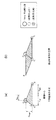
また、従来の技術において、照灯部の照射範囲を制御することで対向車両のドライバを眩惑させないようにするためには、図10(a)に示すように、対向車両101の前照灯102,103の位置に基づきドライバ104を防眩するための遮光領域105aを生成する。
Further, in the conventional technique, in order to prevent the driver of the oncoming vehicle from being dazzled by controlling the irradiation range of the lighting unit, as shown in FIG. , 103 to generate a
しかしながら、上記で説明した従来の技術では、対向車両のドライバ側の前照灯の故障等が原因で対向車両の1灯のみが検出された場合には、対向車両のドライバに対して遮光することができず、防眩できない。 However, in the conventional technique described above, when only one light of the oncoming vehicle is detected due to a failure of the headlight on the driver side of the oncoming vehicle, etc., the light is shielded from the driver of the oncoming vehicle. Cannot be anti-glare.
例えば、図10(b)に示すように、対向車両101の助手席側の前照灯の故障等が原因で対向車両101のドライバ104側の前照灯102の1灯のみが検出された場合、遮光領域105bによって、対向車両101のドライバ104に対して遮光することができるが、図10(c)に示すように、対向車両101のドライバ104側の前照灯の故障等が原因で、対向車両101の助手席側の前照灯103の1灯のみが検出された場合、対向車両101のドライバ104に対して遮光することができず、防眩できていない。
For example, as illustrated in FIG. 10B, when only one of the
1つの前照灯の灯火のみを検出した際に矩形の遮光領域で遮光を行う場合、検出した灯火が左右のいずれの側の灯火であるかを判別できない。そのため、対向車両のドライバを確実に防眩するためには、図10(d)及び図10(e)に示すように、余分な遮光領域106,107を生成する必要がある。
When only one headlamp is detected, if the light is blocked by a rectangular light blocking area, it cannot be determined which side of the lamp is detected. Therefore, in order to reliably prevent the driver of the oncoming vehicle from glare, it is necessary to generate extra
本発明は、上記問題点を解決するためになされたものであり、対向車両の灯火を1灯しか検出できなかった場合であっても、余分な遮光領域を生成することを抑制して、ドライバを防眩することができる照射制御装置を提供することを目的とする。 The present invention has been made in order to solve the above-described problem, and even when only one light of the oncoming vehicle can be detected, the driver is prevented from generating an extra light-shielding region. An object of the present invention is to provide an irradiation control device capable of preventing glare.
(1)上記の目的を達成するため、本発明の照射制御装置は、自車両の前方を撮像する撮像装置によって撮像された撮像画像から、対向車両の灯火位置を検出する灯火位置検出手段と、前記灯火位置検出手段によって検出された前記灯火位置から、予め定められた車両における灯火ペア間の距離だけ右方向に離れた欠損灯火位置を算出する欠損灯火位置算出手段と、前記灯火位置検出手段によって検出された前記灯火位置から、予め定められた車両における灯火位置とドライバの顔位置との高さの差分だけ上方に位置し、かつ、所定の距離だけ右方向に離れた位置を、ドライバ位置として算出するドライバ位置算出手段と、前記灯火位置、前記欠損灯火位置、及び前記ドライバ位置を各頂点とした三角形領域と、前記灯火位置、前記ドライバ位置、及び前記ドライバ位置から前記予め定められた車両における灯火ペア間の距離だけ左方向に離れた位置を各頂点とした三角形領域とを合成して四辺形領域を生成する四辺形領域生成手段と、前記四辺形領域生成手段によって生成された四辺形領域を遮光領域とするように、自車両の前方を照射する照射手段を制御する照射制御手段と、を備える。 (1) In order to achieve the above object, an irradiation control device of the present invention includes a lighting position detection unit that detects a lighting position of an oncoming vehicle from a captured image captured by an imaging device that images the front of the host vehicle. A defective light position calculating means for calculating a defective light position that is separated from the light position detected by the light position detecting means in the right direction by a predetermined distance between the light pairs in the vehicle, and the light position detecting means. The driver position is a position that is located above the detected lamp position by a height difference between the lamp position in the vehicle and the face position of the driver, and that is separated by a predetermined distance to the right. Driver position calculation means for calculating, the lighting position, the defective lighting position, and a triangular area having the driver position as vertices, the lighting position, and the driver And a quadrilateral area generating means for generating a quadrilateral area by synthesizing a triangular area having each vertex as a position separated from the driver position in the left direction by a distance between the light pairs in the predetermined vehicle. And an irradiation control means for controlling the irradiation means for irradiating the front of the host vehicle so that the quadrilateral area generated by the quadrilateral area generation means is a light shielding area.
また、(2)上記の目的を達成するため、本発明の照射制御装置は、自車両の前方を撮像する撮像装置によって撮像された撮像画像から、対向車両の灯火位置を検出する灯火位置検出手段と、前記灯火位置検出手段によって検出された前記灯火位置から、予め定められた車両における灯火ペア間の距離だけ左方向に離れた欠損灯火位置を算出する欠損灯火位置算出手段と、前記灯火位置検出手段によって検出された前記灯火位置から、予め定められた車両における灯火位置とドライバの顔位置との高さの差分だけ上方に位置し、かつ、所定の距離だけ左方向に離れた位置を、ドライバ位置として算出するドライバ位置算出手段と、前記灯火位置、前記欠損灯火位置、及び前記ドライバ位置を各頂点とした三角形領域と、前記灯火位置、前記ドライバ位置、及び前記ドライバ位置から前記予め定められた車両における灯火ペア間の距離だけ右方向に離れた位置を各頂点とした三角形領域とを合成して四辺形領域を生成する四辺形領域生成手段と、前記四辺形領域生成手段によって生成された四辺形領域を遮光領域とするように、自車両の前方を照射する照射手段を制御する照射制御手段と、を備える。 (2) In order to achieve the above object, the irradiation control device of the present invention is a lighting position detection means for detecting the lighting position of the oncoming vehicle from the captured image captured by the imaging device that images the front of the host vehicle. A defective lamp position calculating means for calculating a defective lamp position that is leftward from the lamp position detected by the lamp position detecting means by a predetermined distance between the lamp pairs in the vehicle, and the lamp position detection. A position located above the lamp position detected by the means by a height difference between a predetermined lamp position in the vehicle and the face position of the driver, and left by a predetermined distance to the driver A driver position calculating means for calculating as a position, a triangle area with the lamp position, the missing lamp position, and the driver position as vertices; the lamp position; A quadrilateral area generating means for generating a quadrilateral area by combining a triangular area having each vertex as a position separated from the driver position and the predetermined distance from the driver position to the right by a distance between the lighting pairs in the vehicle. And an irradiation control means for controlling the irradiating means for irradiating the front of the host vehicle so that the quadrilateral area generated by the quadrilateral area generating means is a light shielding area.
(3) 上記(1)又は(2)の照射制御装置において、前記ドライバ位置算出手段は、前記灯火位置検出手段によって検出された前記灯火位置から、予め定められた車両における灯火位置とドライバの顔位置との高さの差分だけ上方に位置し、かつ、予め定められた車両における灯火位置と車両中心との間の距離と予め定められた車両における車両中心とドライバの顔位置との左右方向の距離との差分だけ右方向に離れた位置を、前記ドライバ位置として算出する。 (3) In the irradiation control device according to (1) or (2), the driver position calculating means determines a lighting position and a driver's face in a predetermined vehicle from the lighting position detected by the lighting position detecting means. It is located above the difference in height from the position, and the distance between the lighting position in the predetermined vehicle and the vehicle center and the vehicle center in the predetermined vehicle and the driver's face position in the left-right direction A position that is separated in the right direction by the difference from the distance is calculated as the driver position.
なお、(4)上記(1)から(3)のいずれかに記載の照射制御装置は、前記灯火位置検出手段によって前記対向車両の灯火ペアの灯火位置が検出された場合に、前記対向車両の灯火ペアの灯火位置に基づいて、矩形領域を生成する矩形領域生成手段を更に含み、前記照射制御手段は、前記灯火位置検出手段によって前記対向車両の灯火ペアの灯火位置が検出された場合に、前記矩形領域生成手段によって生成された矩形領域を遮光領域とするように、前記照射手段を制御し、前記灯火位置検出手段によって前記対向車両の1つの灯火位置が検出された場合に、前記四辺形領域生成手段によって生成された四辺形領域を遮光領域とするように、前記照射手段を制御する。 (4) In the irradiation control device according to any one of (1) to (3), when the lighting position of the lighting pair of the oncoming vehicle is detected by the lighting position detecting means, Further comprising a rectangular area generating means for generating a rectangular area based on the lighting position of the lighting pair, the irradiation control means, when the lighting position of the lighting pair of the oncoming vehicle is detected by the lighting position detection means, When the irradiation unit is controlled so that the rectangular region generated by the rectangular region generation unit is a light-shielding region, and when one lighting position of the oncoming vehicle is detected by the lighting position detection unit, the quadrilateral The irradiating means is controlled so that the quadrilateral area generated by the area generating means is a light shielding area.
また、(5)上記の目的を達成するため、本発明の照射制御装置は、自車両の前方を撮像する撮像装置によって撮像された撮像画像から、対向車両の灯火位置を検出する灯火位置検出手段と、前記灯火位置検出手段によって検出された前記灯火位置から、予め定められた車両における灯火位置とドライバの顔位置との高さの差分だけ上方に位置し、かつ、予め定められた車両における灯火位置と車両中心との間の距離と予め定められた車両における車両中心とドライバの顔位置との左右方向の距離との差分だけ右方向に離れた位置を、ドライバ位置として算出するドライバ位置算出手段と、前記灯火位置、前記ドライバ位置、及び前記ドライバ位置から前記予め定められた車両における灯火ペア間の距離だけ左方向に離れた位置を各頂点とした三角形領域、もしくは前記三角形領域に外接する楕円領域又は多角形領域を生成する領域生成手段と、前記領域生成手段によって生成された三角形領域、楕円領域、又は多角形領域を遮光領域とするように、自車両の前方を照射する照射手段を制御する照射制御手段と、を備える。 (5) In order to achieve the above object, the irradiation control device of the present invention is a lighting position detection means for detecting the lighting position of the oncoming vehicle from the captured image captured by the imaging device that images the front of the host vehicle. And a lamp in the vehicle that is positioned above the lamp position detected by the lamp position detecting means by a height difference between the lamp position in the vehicle and the face position of the driver. A driver position calculation means for calculating a driver position that is a position separated in the right direction by a difference between a distance between the position and the vehicle center and a distance in the left-right direction between the vehicle center and the driver's face position in a predetermined vehicle. And each lighting position, the driver position, and a position separated from the driver position in the left direction by a distance between the lighting pair in the predetermined vehicle. A triangular area, or an area generating means for generating an elliptical area or a polygonal area circumscribing the triangular area, and a triangular area, an elliptical area, or a polygonal area generated by the area generating means as a light shielding area, Irradiation control means for controlling irradiation means for irradiating the front of the host vehicle.
また、(5)上記の目的を達成するため、本発明の照射制御装置は、自車両の前方を撮像する撮像装置によって撮像された撮像画像から、対向車両の灯火位置を検出する灯火位置検出手段と、前記灯火位置検出手段によって検出された前記灯火位置から、予め定められた車両における灯火位置とドライバの顔位置との高さの差分だけ上方に位置し、かつ、予め定められた車両における灯火位置と車両中心との間の距離と予め定められた車両における車両中心とドライバの顔位置との左右方向の距離との差分だけ左方向に離れた位置を、ドライバ位置として算出するドライバ位置算出手段と、前記灯火位置、前記ドライバ位置、及び前記ドライバ位置から前記予め定められた車両における灯火ペア間の距離だけ右方向に離れた位置を各頂点とした三角形領域、もしくは前記三角形領域に外接する楕円領域又は多角形領域を生成する領域生成手段と、前記領域生成手段によって生成された三角形領域、楕円領域、又は多角形領域を遮光領域とするように、自車両の前方を照射する照射手段を制御する照射制御手段と、を備える。 (5) In order to achieve the above object, the irradiation control device of the present invention is a lighting position detection means for detecting the lighting position of the oncoming vehicle from the captured image captured by the imaging device that images the front of the host vehicle. And a lamp in the vehicle that is positioned above the lamp position detected by the lamp position detecting means by a height difference between the lamp position in the vehicle and the face position of the driver. Driver position calculating means for calculating a driver position that is a distance leftward by a difference between a distance between the position and the vehicle center and a distance in the left-right direction between the vehicle center and the driver's face position in a predetermined vehicle. And each lighting position, the driver position, and a position separated from the driver position in the right direction by a distance between the lighting pair in the vehicle determined in advance. A triangular area, or an area generating means for generating an elliptical area or a polygonal area circumscribing the triangular area, and a triangular area, an elliptical area, or a polygonal area generated by the area generating means as a light shielding area, Irradiation control means for controlling irradiation means for irradiating the front of the host vehicle.
なお、(6)上記(4)又は(5)の照射制御装置は、前記灯火位置検出手段によって前記対向車両の灯火ペアの灯火位置が検出された場合に、前記対向車両の灯火ペアの灯火位置に基づいて、矩形領域を生成する矩形領域生成手段を更に含み、前記照射制御手段は、前記灯火位置検出手段によって前記対向車両の灯火ペアの灯火位置が検出された場合に、前記矩形領域生成手段によって生成された矩形領域を遮光領域とするように、前記照射手段を制御し、前記灯火位置検出手段によって前記対向車両の1つの灯火位置が検出された場合に、前記領域生成手段によって生成された三角形領域、楕円領域、又は多角形領域を遮光領域とするように、前記照射手段を制御する。 (6) The irradiation control device according to (4) or (5) described above, wherein the lighting position of the lighting pair of the oncoming vehicle is detected when the lighting position detecting means detects the lighting position of the lighting pair of the oncoming vehicle. Further comprising: a rectangular area generating means for generating a rectangular area, wherein the irradiation control means, when the lighting position of the oncoming vehicle is detected by the lighting position detecting means, the rectangular area generating means. The irradiation means is controlled so as to make the rectangular area generated by the light-shielding area, and when one lighting position of the oncoming vehicle is detected by the lighting position detection means, the irradiation means is generated by the area generation means. The irradiation means is controlled so that a triangular area, an elliptical area, or a polygonal area is a light shielding area.
また、上記各々の照射制御装置は、前記撮像装置の光軸と前記照灯手段の光軸とは、合わせて設置される。 Further, each of the irradiation control devices is installed such that the optical axis of the imaging device and the optical axis of the illumination means are combined.
本発明に係る照射制御装置は、対向車両の灯火を1灯しか検出できなかった場合であっても、余分な遮光領域を生成することを抑制して、ドライバを防眩することができる、という優れた効果を有する。 The irradiation control device according to the present invention can prevent the driver from glare by suppressing the generation of an extra light-shielding region even when only one light from the oncoming vehicle can be detected. Has an excellent effect.
以下、図面を参照して、本発明に係る実施の形態について詳細に説明する。 Hereinafter, embodiments of the present invention will be described in detail with reference to the drawings.
<第1の実施の形態例> <First Embodiment>
図1は、第1の実施の形態に係る照射制御装置としての配光制御装置の構成例を示している。なお、本第1の実施の形態では、車両に搭載され、撮像された前方画像に基づいてLEDマトリクスランプからなるヘッドランプの照灯制御を行う車載用照明システムに本発明を適用した場合を例に説明する。 FIG. 1 shows a configuration example of a light distribution control device as an irradiation control device according to the first embodiment. In the first embodiment, a case where the present invention is applied to an in-vehicle illumination system that is mounted on a vehicle and controls lighting of a headlamp composed of an LED matrix lamp based on a captured front image is taken as an example. Explained.
図1に示すように、第1の実施の形態に係る車載用照明システム10は、自車両の前方の画像を撮像するCCDカメラ等からなる撮像装置2と、撮像された前方画像に基づいて、自車両に設けられたLEDマトリクスランプからなる本発明に係る照射手段としてのヘッドランプ3の照灯を制御する配光制御装置1とを備えている。なお、撮像装置2によって出力される画像は、濃淡画像及びカラー画像の何れであってもよい。
As shown in FIG. 1, the in-vehicle illumination system 10 according to the first embodiment is based on an
配光制御装置1は、CPU(Central Processing Unit)、CPUに本発明に係る配光制御処理動作を実行させるためのプログラム等を記憶したROM(Read Only Memory)、データ等を記憶するRAM(Random Access Memory)、及びこれらを接続するバスを含んで構成されており、プログラムに基づくコンピュータ処理で実現される機能として、点灯検出部4、3次元位置算出部5、ペアリング判定部6、矩形遮光領域生成部7、四辺形領域生成処理部8、及び、照射制御部9を備えている。なお、点灯検出部4及び3次元位置算出部5は、本発明に係る灯火位置検出手段の一例である。
The light
点灯検出部4は、撮像装置2によって撮像された撮像画像から、パターン認識手法などを用いて対向車両のヘッドランプの検出を行う。
The
3次元位置算出部5は、点灯検出部4で検出された対向車両のヘッドランプに基づき、当該ヘッドランプの自車両からの3次元位置を算出する。なお、撮像装置2の光軸と自車両のヘッドランプの光軸とが同じ位置関係にある場合には、2次元位置を算出することでも良い。
The three-dimensional
ペアリング判定部6は、3次元位置算出部5で算出された対向車両のヘッドランプの3次元位置に基づいて、近傍同士のヘッドランプのペアリングを行い、1灯のみの検出であるか、2灯での検出であるかを判定する。なお、このようなヘッドランプのペアリングの判定は、特開2010−221756号公報に記載の車両灯火判定方法を用いて行うことができる。例えば、対向車両の片側のヘッドランプが故障で点灯していない場合、又は、点灯検出部4で対向車両の1灯のみが検出された場合等において、1灯のみの検出であると判定される。
Based on the three-dimensional position of the headlamps of the oncoming vehicle calculated by the three-dimensional
矩形遮光領域生成部7は、ペアリング判定部6による判定で対向車両の2灯が検出されたと判定された場合に、2つの灯火の各々の位置に基づいて対向車両の車幅を算出し、算出した車幅に合わせた横幅と予め定められた高さとからなる矩形領域を生成する。
When it is determined by the
四辺形領域生成処理部8は、ペアリング判定部6による判定で、対向車両の1灯のみが検出されたと判定された場合に、検出された1つの灯火の位置を頂点の1つとした2つの三角形を合成した四辺形領域を遮光領域として生成する。
When the determination by the
照射制御部9は、矩形遮光領域生成部7で生成された矩形領域、又は四辺形領域生成処理部8で生成された四辺形領域を遮光領域とするように照射パターンを生成し、自車両のヘッドランプを制御する。例えば、遮光領域に対応する自車両のヘッドランプによる照射部分の照度を低減させる照射パターンを生成し、照射制御を行う。
The
四辺形領域生成処理部8はプログラムに基づくコンピュータ処理で実現される機能として欠損灯火位置算出部8a、ドライバ位置算出部8b、及び、四辺形領域生成部8cを備えている。
The quadrilateral area
欠損灯火位置算出部8aは、点灯検出部4及び3次元位置算出部5によって検出され算出された灯火位置から、予め定められた車両における灯火ペア間の距離だけ右方向に離れた欠損灯火位置を算出する。
The deficient lamp position calculation unit 8a determines a deficient lamp position that is separated from the lamp position detected and calculated by the
ドライバ位置算出部8bは、点灯検出部4及び3次元位置算出部5によって検出され算出された灯火位置から、予め定められた標準的な車両における灯火位置とドライバの顔位置との高さの差分だけ上方に位置し、かつ、予め定められた標準的な車両における灯火位置と車両中心との間の距離と予め定められた車両における車両中心とドライバの顔位置との左右方向の距離との差分だけ右方向に離れた位置を、ドライバ位置として算出する。
The driver
四辺形領域生成部8cは、点灯検出部4及び3次元位置算出部5によって検出され算出された灯火位置、欠損灯火位置算出部8aによって算出された欠損灯火位置、及び、ドライバ位置算出部8bによって算出されたドライバ位置を各頂点とした三角形と、灯火位置、ドライバ位置、及びドライバ位置から予め定められた標準的な車両における灯火ペア間の距離だけ左方向に離れた位置を各頂点とした三角形領域とを合成して四辺形領域を生成する。
The quadrangular
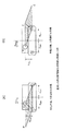
このような四辺形領域生成処理部8による四辺形領域の遮光領域の生成処理動作について図2を用いて説明する。
The operation for generating the light shielding area of the quadrilateral area by the quadrilateral area
なお、対向車両が右ハンドルの場合を例として説明する。 The case where the oncoming vehicle is a right steering wheel will be described as an example.
図2(a)に示すように、点灯検出部4及び3次元位置算出部5によって検出され算出された対向車両の灯火位置Aを三角形の左下の頂点とし、予め定められた標準的な車両における車両中心から灯火位置A,Bまでの距離をdlight、予め定められた標準的な車両における灯火位置Aと車両中心との間の距離(dlight)と予め定められた車両における車両中心とドライバの顔位置Cとの左右方向の距離との差分だけ右方向に離れた位置、すなわち、当該車両中心からドライバの顔位置Cまでの距離をddriver、予め定められた標準的な車両における灯火位置A,Bからドライバの顔位置Cまでの高さの差をdheightとすることで、底辺の長さが2×dlight、高さがdheightとなる三角形ABCを生成する。
As shown in FIG. 2 (a), the lighting position A of the oncoming vehicle detected and calculated by the
そして、図2(b)に示すように、このように生成した三角形領域ABCと、灯火位置、ドライバ位置、及びドライバ位置から予め定められた車両における灯火ペア間の距離だけ左方向に離れた位置B’を各頂点とした三角形領域AB’Cとを合成して四辺形領域を生成する。すなわち、生成した三角形領域ABC及び三角形領域AB’Cを、辺ACを対角線として合成して、四辺形領域を生成する。 Then, as shown in FIG. 2 (b), the triangle area ABC thus generated, and the position that is leftward from the lamp position, the driver position, and the distance between the lamp pair in the vehicle determined in advance from the driver position. A quadrilateral area is generated by combining the triangular area AB′C with B ′ as the vertices. That is, the generated triangular area ABC and triangular area AB′C are combined with the side AC as a diagonal line to generate a quadrilateral area.
生成した四辺形領域を遮光領域として自車両のヘッドランプの照射を制御することにより、このように1灯を検出した場合には、図3(a)及び図3(b)に示すように、灯火を検出した位置に三角形の頂点Aが配置された遮光領域が形成されるように自車両のヘッドランプの照射を制御することとなり、ドライバ側の灯火が欠損した場合、及び助手席側の灯火が欠損した場合のいずれの場合であっても、右ハンドルの対向車両のドライバの顔位置を遮光することで防眩できる。 When one lamp is detected in this way by controlling the irradiation of the headlamp of the host vehicle using the generated quadrangular area as a light-shielding area, as shown in FIGS. 3 (a) and 3 (b), Irradiation of the headlamp of the host vehicle is controlled so that a light-shielding area in which a triangular vertex A is arranged is formed at the position where the lamp is detected. In any case where the deficiency is lost, it is possible to prevent glare by shielding the face position of the driver of the oncoming vehicle on the right handle.
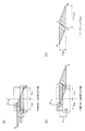
次に、図4を用いて、対向車両のドライバ側の前照灯の1灯のみが検出された際に、四辺形領域生成処理部8により生成された四辺形領域で遮光を行う場合の遮光領域の面積について説明する。
Next, with reference to FIG. 4, when only one headlight on the driver side of the oncoming vehicle is detected, the light shielding is performed in the case where the quadrangular region generated by the quadrangular region
なお、図4においては、対向車両の前照灯とドライバの頭部を点として容易なモデルとして示し、対向車両に対して自車両の前方の余分な遮光部分を優先的に低減させている状態を示している。 FIG. 4 shows an easy model with the headlight of the oncoming vehicle and the head of the driver as points, and a state in which an extra light-shielding portion in front of the own vehicle is preferentially reduced with respect to the oncoming vehicle. Is shown.
また、予め定められた対向車両の車両中心から灯火位置までの距離dlightは、予め定められた対向車両の車両中心からドライバまでの距離ddriverより大きいものとする(dlight>ddriver)が、逆の場合でも結果は同じである。 Further, the predetermined distance d light from the vehicle center of the oncoming vehicle to the lighting position is larger than the predetermined distance d driver from the vehicle center of the oncoming vehicle to the driver (d light > d driver ). In the opposite case, the result is the same.
図4(a)では、対向車両のドライバ側の前照灯の1灯のみが検出された場合における四辺形の遮光領域を示し、図4(b)では、対向車両の助手席側の前照灯の1灯のみが検出された場合における四辺形の遮光領域を示しており、いずれの場合においても対向車両のドライバの顔部分が遮光領域に含まれている。 FIG. 4 (a) shows a quadrilateral light shielding area when only one of the headlights on the driver side of the oncoming vehicle is detected, and FIG. 4 (b) shows the headlight on the passenger seat side of the oncoming vehicle. A quadrilateral light shielding area when only one of the lights is detected is shown. In any case, the face portion of the driver of the oncoming vehicle is included in the light shielding area.
図4(a)及び図4(b)で示す各々の四辺形の遮光領域の面積S’は、図4(c)で示すように、「2×dlight×dheight」として算出される。 The area S ′ of each quadrangular light shielding region shown in FIGS. 4A and 4B is calculated as “2 × d light × d height ” as shown in FIG. 4C.
図4(a)及び図4(b)のいずれの四辺形遮光領域であっても、対向車両のドライバの顔部分が遮光領域として含まれており、対向車両のドライバを確実に防眩することができる。その結果、検出した灯火が左右のいずれの側(ドライバ側、助手席側)の灯火であるかを判別できない場合であっても、対向車両のドライバを確実に防眩するために必要な四辺形領域の面積S’は「2×dlight×dheight」となる。 4A and 4B, the face portion of the driver of the oncoming vehicle is included as the light shielding region, and the driver of the oncoming vehicle is surely anti-glare. Can do. As a result, the quadrilateral necessary to ensure anti-glare for the driver of the oncoming vehicle, even if it is not possible to determine whether the detected light is on the left or right side (driver side, passenger side) The area S ′ of the region is “2 × d light × d height ”.
このように、四辺形領域生成処理部8により生成された四辺形の遮光領域で遮光を行うことにより、遮光領域の面積を減少させることができる。
In this way, by performing light shielding with the quadrilateral light shielding region generated by the quadrilateral region
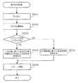
次に、図5を用いて、配光制御装置1の点灯検出部4、3次元位置算出部5、ペアリング判定部6、矩形遮光領域生成部7、四辺形領域生成処理部8、及び、照射制御部9による本発明係る配光制御処理動作を説明する。
Next, using FIG. 5, the
点灯検出部4は、撮像装置2によって撮像された撮像画像から、パターン認識手法などを用いて対向車両のヘッドランプの灯火検出を行う(ステップS501)。
The
3次元位置算出部5は、点灯検出部4で検出された対向車両のヘッドランプに基づき、当該ヘッドランプの自車両からの3次元位置を算出する(ステップS502)。なお、撮像装置2の光軸と自車両のヘッドランプの光軸とが同じ位置関係にある場合には、2次元位置を算出することでも良い。
The three-dimensional
ペアリング判定部6は、3次元位置算出部5で算出された3次元位置に基づいて近傍同士のヘッドランプのペアリングを行い、1灯のみの検出であるか、2灯での検出であるかを判定する(ステップS503)。
The
ペアリング判定部6による判定で対向車両の2灯が検出された場合、矩形遮光領域生成部7は、2つの灯火の各々の位置に基づいて対向車両の車幅を算出し、算出した車幅に合わせた横幅と予め定められた高さとからなる矩形領域を遮光領域として生成する(ステップS504)。
When two lights of the oncoming vehicle are detected by the determination by the
また、ペアリング判定部6による判定で、点灯検出部4で対向車両の1灯のみが検出されたと判定された場合、四辺形領域生成処理部8は、検出された1つの灯火の位置を頂点の1つとした2つの三角形領域を合成した四辺形領域を遮光領域として生成する(ステップS505)。
Further, when it is determined by the
照射制御部9は、矩形遮光領域生成部7で生成された矩形遮光領域、又は、四辺形領域生成処理部8で生成された四辺形遮光領域で遮光するように照射パターンを生成し、自車両のヘッドランプの照射制御を行う(ステップS506)。
The
<第2の実施の形態例> <Second Embodiment>
次に、図6を用いて、本発明の第2の実施の形態について説明する。なお、本第2の実施の形態においても、第1の実施の形態と同様、車両に搭載され、撮像された前方画像に基づいてLEDマトリクスランプからなるヘッドランプの照灯制御を行う車載用照明システムに本発明を適用した場合を例に説明する。 Next, a second embodiment of the present invention will be described with reference to FIG. In the second embodiment, as in the first embodiment, the vehicle-mounted illumination is mounted on the vehicle and controls the lighting of the headlamp composed of the LED matrix lamp based on the captured front image. A case where the present invention is applied to a system will be described as an example.
図6に示すように、第2の実施の形態に係る車載用照明システム20は、図1で示した第1の実施の形態に係る車載用照明システム10と同様の撮像装置2及びヘッドランプ3と共に、照射制御装置としての配光制御装置1aを備えている。
As shown in FIG. 6, the in-vehicle illumination system 20 according to the second embodiment is the same as the in-vehicle illumination system 10 according to the first embodiment shown in FIG. In addition, a light
配光制御装置1aは、図1で示した車載用照明システム10の配光制御装置1と同様に、CPU、ROM、RAM、及びバスを含んで構成されており、プログラムに基づくコンピュータ処理で実現される機能として、点灯検出部4a、3次元位置算出部5a、ペアリング判定部6a、矩形遮光領域生成部7a、及び、照射制御部9aを備え、四辺形領域生成処理部8の代わりに遮光領域生成処理部80を備えている。
Like the light
遮光領域生成処理部80は、図1で示した車載用照明システム10の配光制御装置1と同様のドライバ位置算出部8bを備えると共に、四辺形領域生成部8cの代わりに遮光領域生成部80cを備えている。
The light-shielding region
点灯検出部4a、3次元位置算出部5a、ペアリング判定部6a、及び、矩形遮光領域生成部7aは、各々、図1で示した車載用照明システム10の配光制御装置1における点灯検出部4、3次元位置算出部5、ペアリング判定部6、及び、矩形遮光領域生成部7と同様にして動作を行い、例えば、矩形遮光領域生成部7aは、ペアリング判定部6aによる判定で対向車両の2灯が検出された場合に、2つの灯火の各々の位置に基づいて対向車両の車幅を算出し、算出した車幅に合わせた横幅と予め定められた高さとからなる矩形領域を遮光領域として生成する。
The
遮光領域生成処理部80は、ペアリング判定部6aによる判定で、対向車両の1灯のみが検出されたと判定された場合において、検出された1つの灯火の位置を頂点の1つとした三角形領域を遮光領域として生成する。
When the
照射制御部9aは、矩形遮光領域生成部7aで生成された矩形領域、又は遮光領域生成処理部80で生成された三角形領域を遮光領域とするように照射パターンを生成し、自車両のヘッドランプの照射制御を行う。
The
遮光領域生成処理部80において、ドライバ位置算出部8bは、点灯検出部4a及び3次元位置算出部5aによって検出され算出された灯火位置から、予め定められた車両における灯火位置とドライバの顔位置との高さの差分だけ上方に位置し、かつ、予め定められた車両における灯火位置と車両中心との間の距離と予め定められた車両における車両中心とドライバの顔位置との左右方向の距離との差分だけ右方向に離れた位置を、ドライバ位置として算出する。
In the light-shielding region
そして、遮光領域生成部80cは、灯火位置、ドライバ位置、及びドライバ位置から予め定められた車両における灯火ペア間の距離だけ左方向に離れた位置を各頂点とした三角形領域を遮光領域として生成する。
Then, the light-shielding
このような遮光領域生成処理部80により生成される三角形領域の遮光領域は、図2、図3、及び、図4の各々で示された図1における車載用照明システム10の配光制御装置1で生成された四辺形領域の図の左側の三角形AB’Cの領域であり、いずれの場合も対向車両のドライバの顔部分を含んでおり、ドライバの顔部分を遮光することで防眩することができる。
The light shielding area of the triangular area generated by such a light shielding area
特に、遮光領域生成処理部80により生成される三角形領域の遮光領域の面積は、図2、図3、及び、図4の各々で示された第1の実施の形態に係る車載用照明システム10の配光制御装置1で生成された四辺形領域の遮光領域の面積の半分となり、さらに余分な遮光領域を低減させることができる。
In particular, the area of the light shielding region of the triangular region generated by the light shielding region
このような遮光領域生成処理部80による三角形領域の遮光領域の生成処理動作について図7を用いて説明する。
An operation of generating a light shielding area of a triangular area by such a light shielding area
なお、対向車両が右ハンドルの場合を例として説明する。 The case where the oncoming vehicle is a right steering wheel will be described as an example.
図7(a)に示すように、遮光領域生成処理部80のドライバ位置算出部8bは、点灯検出部4a及び3次元位置算出部5aによって検出され算出されたドライバ席側の灯火位置(A)から、予め定められた車両における灯火位置とドライバの顔位置との高さの差分(dheight)だけ上方に位置し、かつ、予め定められた車両における灯火位置(A,B)と車両中心との間の距離(dlight)と予め定められた車両における車両中心とドライバの顔位置との左右方向の距離(ddriver)との差分(dlight- ddriver)だけ右方向に離れた位置を、ドライバ位置(C)として算出する。
As shown in FIG. 7A, the driver
そして、遮光領域生成部80cは、灯火位置(A)、ドライバ位置(C)、及びドライバ位置(C)から予め定められた車両における灯火ペア間の距離(dlight + dlight )だけ左方向に離れた位置(B’)を各頂点とした三角形領域を遮光領域として生成する。
Then, the light shielding
このように、遮光領域生成処理部80により生成される三角形領域(AB’C)の遮光領域は、上記図7(a)に示すように助手席側(P席側)の灯火が欠損している場合であっても、対向車両のドライバの顔部分(C)を含んでおり、ドライバの顔部分を遮光することで防眩することができる。
As described above, the light shielding area of the triangular area (AB′C) generated by the light shielding area
また、図7(b)に示すように、ドライバ席側(D席側)の灯火が欠損している場合であっても、遮光領域生成処理部80により生成される三角形領域(AB’C)の遮光領域は、対向車両のドライバの顔部分(ここではB’となる)を含んでおり、ドライバの顔部分を遮光することで防眩することができる。
Further, as shown in FIG. 7B, even when the driver seat side (D seat side) lights are missing, the triangular region (AB′C) generated by the light shielding region
次に、図8を用いて、図1における自車両のヘッドランプ3の光軸と撮像装置2の光軸とをあわせて設置した際の遮光領域の画像面上での位置と遮光対象での位置について説明する。
Next, referring to FIG. 8, the position of the light shielding area on the image plane and the light shielding target when the optical axis of the
図8に示すように、図1における自車両のヘッドランプ3の光軸と撮像装置2(カメラ)の光軸とをあわせて設置した場合、撮像装置2で対向車両(被写体)のヘッドランプからの光を受ける場合と、自車両のヘッドランプ3から光を対向車両(遮光対象)に照射する場合とは、反対の過程であり、撮像装置2の撮影画角(カメラ画角)とヘッドランプ3の照射角との違いによる座標変換は二次元平面上(画面上)で行うことができるため、自車両と対向車両との距離を求める必要がなく、自車両と対向車両との距離に関係なく、画像面上での遮光領域の位置と、対向車両(遮光対象)における遮光領域の位置と、を精度良く設定することができる。
As shown in FIG. 8, when the optical axis of the
以上、各図を用いて説明したように、本実施の形態の配光制御装置においては、自車両の前方を撮像する撮像装置によって撮像された撮像画像から、対向車両の灯火位置を検出し、検出した灯火位置から、予め定められた車両における灯火ペア間の距離だけ右方向に離れた欠損灯火位置を算出すると共に、検出した灯火位置から、予め定められた車両における灯火位置とドライバの顔位置との高さの差分だけ上方に位置し、かつ、予め定められた車両における灯火位置と車両中心との間の距離と予め定められた車両における車両中心とドライバの顔位置との左右方向の距離との差分だけ右方向に離れた位置を、ドライバ位置として算出する。そして、灯火位置、欠損灯火位置、及びドライバ位置を各頂点とした三角形領域と、灯火位置、ドライバ位置、及びドライバ位置から予め定められた車両における灯火ペア間の距離だけ左方向に離れた位置を各頂点とした三角形領域とを合成して四辺形領域を生成し、生成した四辺形領域を遮光領域とするように、自車両の前方を照射するヘッドランプを制御する。 As described above with reference to the respective drawings, in the light distribution control device of the present embodiment, the lighting position of the oncoming vehicle is detected from the captured image captured by the imaging device that images the front of the host vehicle, From the detected lighting position, a defective lighting position that is separated to the right by a distance between the lighting pair in a predetermined vehicle is calculated, and from the detected lighting position, the lighting position in the predetermined vehicle and the driver's face position are calculated. The distance between the lighting position in the predetermined vehicle and the vehicle center and the distance in the left-right direction between the vehicle center in the predetermined vehicle and the driver's face position. The position separated in the right direction by the difference between is calculated as the driver position. Then, a triangular area with the lighting position, the defective lighting position, and the driver position as vertices, and a position that is separated from the lighting position, the driver position, and the lighting position in the left direction by a predetermined distance between the lighting pair in the vehicle. The headlamp that irradiates the front of the host vehicle is controlled so as to generate a quadrilateral area by combining the triangular areas that are the vertices, and to set the generated quadrilateral area as a light-shielding area.
また、灯火位置、ドライバ位置、及びドライバ位置から予め定められた車両における灯火ペア間の距離だけ左方向に離れた位置を各頂点とした三角形領域を生成し、生成した三角形領域を遮光領域とするように、ヘッドランプを制御する。 In addition, a triangular area is generated with each light point, a driver position, and a position separated from the driver position leftward by a predetermined distance between the light pair in the vehicle as a vertex, and the generated triangular area is defined as a light shielding area. As such, the headlamp is controlled.
なお、対向車両の灯火ペアの灯火位置が検出された場合には、対向車両の灯火ペアの灯火位置に基づいて、矩形領域を生成し、生成した矩形領域を遮光領域とするように、ヘッドランプを制御し、対向車両の1つの灯火位置が検出された場合に、生成した四辺形領域、又は三角形領域を遮光領域とするように、ヘッドランプを制御する。 When the lighting position of the on-vehicle lighting pair is detected, a headlamp is generated so that a rectangular area is generated based on the lighting position of the on-vehicle lighting pair, and the generated rectangular area is used as a light shielding area. When one lighting position of the oncoming vehicle is detected, the headlamp is controlled so that the generated quadrilateral area or triangular area is the light shielding area.
このような遮光領域の生成技術では、対向車両の1つのヘッドランプ(前照灯)のみから対向車両のドライバを防眩できる遮光領域を生成することができるので、例えば、対向車両が片眼であっても、対向車両のドライバを確実に防眩することができる。 In such a light-blocking region generation technique, a light-blocking region that can prevent the driver of the oncoming vehicle from glare can be generated from only one headlamp (headlight) of the oncoming vehicle. Even if it exists, the driver of the oncoming vehicle can be reliably anti-glare.
また、このようにして生成される遮光領域の面積は、従来技術で生成される矩形の遮光領域の面積と比較して、半分又は1/4に削減することができるので、余分な遮光領域を生成することを抑制して、他の領域に対する視認性を向上させることができる。 Further, the area of the light-shielding region generated in this way can be reduced to half or ¼ compared to the area of the rectangular light-shielding region generated by the conventional technique, so that the extra light-shielding region can be reduced. Generation | occurrence | production can be suppressed and the visibility with respect to another area | region can be improved.
なお、本発明は、各図を用いて説明した実施の形態例に限定されるものではなく、その要旨を逸脱しない範囲において種々変更して適用することが可能である。例えば、本実施の形態例では、四辺形領域又は三角形領域を遮光領域とした照射パターンを用いているが、当該三角形領域に外接する楕円形領域又は多角形領域を遮光領域とした照射パターンを用いても良い。 Note that the present invention is not limited to the embodiment described with reference to the drawings, and various modifications can be applied without departing from the scope of the invention. For example, in this embodiment, an irradiation pattern using a quadrangular region or a triangular region as a light shielding region is used, but an irradiation pattern using an elliptical region or a polygonal region circumscribing the triangular region as a light shielding region is used. May be.
例えば、図9に示すように、図6の遮光領域生成処理部80により生成された図7(a)における三角形領域AB’Cに外接する矩形領域91aを生成して、照射制御部9aは、当該矩形領域91aを遮光領域とするように照射パターンを生成し、自車両のヘッドランプの照射制御を行う。
For example, as shown in FIG. 9, the
図9に示すように、生成された矩形領域91aの遮光領域は、対向車両のドライバの顔部分(C)を含んでおり、ドライバの顔部分を遮光することで防眩することができる。 As shown in FIG. 9, the light-shielding area of the generated rectangular area 91a includes the face part (C) of the driver of the oncoming vehicle, and can be anti-glare by shielding the face part of the driver.
なお、図9においても、対向車両の前照灯とドライバの頭部を点として容易なモデルとして示し、対向車両に対して自車両の前方の余分な遮光部分を優先的に低減させている状態を示している。 In FIG. 9 as well, the headlamps of the oncoming vehicle and the driver's head are shown as easy models, and an unnecessary light-shielding portion in front of the own vehicle is preferentially reduced with respect to the oncoming vehicle. Is shown.
また、予め定められた対向車両の車両位置から灯火位置までの距離dlightは、予め定められた対向車両の車両中心からドライバまでの距離ddriverより大きいものとする(dlight>ddriver)が、逆の場合でも結果は同じである。 The predetermined distance d light from the vehicle position of the oncoming vehicle to the lighting position is greater than the predetermined distance d driver from the vehicle center of the oncoming vehicle to the driver (d light > d driver ). In the opposite case, the result is the same.
また、検出した灯火位置から、予め定められた車両における灯火位置とドライバの顔位置との高さの差分だけ上方に位置し、かつ、予め定められた車両における灯火位置と車両中心との間の距離と予め定められた車両における車両中心とドライバの顔位置との左右方向の距離との差分だけ右方向に離れた位置を、ドライバ位置として算出する場合を例に説明したが、これに限定されるものではない。例えば、検出した灯火位置から、予め定められた車両における灯火位置とドライバの顔位置との高さの差分だけ上方に位置し、かつ、予め定められた距離だけ右方向に離れた位置を、ドライバ位置として算出するようにしてもよい。 Further, it is located above the detected lighting position by a height difference between the lighting position in the predetermined vehicle and the face position of the driver, and between the lighting position in the predetermined vehicle and the vehicle center. The case where the driver position is calculated as an example where the distance and the position separated in the right direction by the difference between the distance between the vehicle center in a predetermined vehicle and the driver's face position in the left-right direction has been described as an example. It is not something. For example, a position that is located above the detected lighting position by a height difference between a lighting position in a predetermined vehicle and the face position of the driver and that is separated by a predetermined distance to the right is It may be calculated as a position.
また、本実施の形態例では、対向車両が右ハンドルの場合に適用する例で説明したが、対向車両が左ハンドルの場合にも適用できる。 Further, in the present embodiment, an example in which the oncoming vehicle is a right handle has been described, but the present invention can also be applied to a case where the oncoming vehicle is a left handle.
例えば、対向車両が左ハンドルの場合には、欠損灯火位置算出部8aにより、点灯検出部4及び3次元位置算出部5によって検出され算出された灯火位置から、予め定められた車両における灯火ペア間の距離だけ左方向に離れた欠損灯火位置を算出し、ドライバ位置算出部8bにより、点灯検出部4及び3次元位置算出部5によって検出され算出された灯火位置から、予め定められた車両における灯火位置とドライバの顔位置との高さの差分だけ上方に位置し、かつ、所定の距離(例えば、予め定められた車両における灯火位置と車両中心との間の距離と、予め定められた車両における車両中心とドライバの顔位置との左右方向の距離との差分)だけ左方向に離れた位置を、ドライバ位置として算出し、四辺形領域生成部8cにより、灯火位置、欠損灯火位置、及びドライバ位置を各頂点とした三角形領域と、灯火位置、ドライバ位置、及びドライバ位置から予め定められた車両における灯火ペア間の距離だけ右方向に離れた位置を各頂点とした三角形領域とを合成して四辺形領域を生成し、照射制御部9により、生成された四辺形領域を遮光領域とするように、自車両の前方を照射するヘッドランプを制御する。
For example, when the oncoming vehicle is a left steering wheel, a lamp pair in a predetermined vehicle is determined from the lamp positions detected and calculated by the
また、遮光領域生成部80cにより、灯火位置、ドライバ位置、及びドライバ位置から予め定められた車両における灯火ペア間の距離だけ右方向に離れた位置を各頂点とした三角形領域、又は当該三角形領域に外接する楕円領域又は多角形領域を生成し、照射制御部9aにより、生成された三角形領域、楕円領域、又は多角形領域を遮光領域とするように、自車両の前方を照射するヘッドランプを制御する。
In addition, the light shielding
また、本実施の形態例では、本実施の形態の配光制御装置の各機能をプログラムに基づくCPUの処理で実現しているが、論理素子回路からなるハードウェア構成とすることでも良い。 In this embodiment, each function of the light distribution control device of this embodiment is realized by a CPU process based on a program. However, a hardware configuration including a logic element circuit may be used.
1,1a 配光制御装置
2 撮像装置
3 ヘッドランプ(自車両の前照灯)
4,4a 点灯検出部
5,5a 3次元位置算出部
6,6a ペアリング判定部
7,7a 矩形遮光領域生成部
8 四辺形領域生成処理部
8a 欠損灯火位置算出部
8b ドライバ位置算出部
8c 四辺形領域生成部
9,9a 照射制御部
10,20 車載用照明システム
80 遮光領域生成処理部
80c 遮光領域生成部
91a 矩形領域
101 対向車両
102,103 ヘッドランプ(対向車両の前照灯)
104 ドライバ
105a,105b,105c 矩形遮光領域
106,107 余分な遮光領域
1, 1a Light
4, 4a
104
Claims (6)
前記灯火位置検出手段によって検出された前記灯火位置から、予め定められた車両における灯火ペア間の距離だけ右方向に離れた欠損灯火位置を算出する欠損灯火位置算出手段と、
前記灯火位置検出手段によって検出された前記灯火位置から、予め定められた車両における灯火位置とドライバの顔位置との高さの差分だけ上方に位置し、かつ、所定の距離だけ右方向に離れた位置を、ドライバ位置として算出するドライバ位置算出手段と、
前記灯火位置、前記欠損灯火位置、及び前記ドライバ位置を各頂点とした三角形領域と、前記灯火位置、前記ドライバ位置、及び前記ドライバ位置から前記予め定められた車両における灯火ペア間の距離だけ左方向に離れた位置を各頂点とした三角形領域とを合成して四辺形領域を生成する四辺形領域生成手段と、
前記四辺形領域生成手段によって生成された四辺形領域を遮光領域とするように、自車両の前方を照射する照射手段を制御する照射制御手段と、
を備えた照射制御装置。 A lighting position detection means for detecting a lighting position of an oncoming vehicle from a captured image captured by an imaging device that images the front of the host vehicle;
A deficient lamp position calculating means for calculating a deficient lamp position that is separated from the lamp position detected by the lamp position detecting means in the right direction by a distance between lamp pairs in a predetermined vehicle;
It is located above the lighting position detected by the lighting position detection means by a height difference between a predetermined lighting position in the vehicle and the face position of the driver, and is separated to the right by a predetermined distance. Driver position calculating means for calculating the position as the driver position;
A triangle region with the light position, the defective light position, and the driver position as vertices, and a left distance from the light position, the driver position, and a predetermined distance between the light pair in the vehicle from the driver position. A quadrilateral region generating means for generating a quadrilateral region by combining triangular regions with vertices at positions separated from each other;
Irradiation control means for controlling the irradiation means for irradiating the front of the host vehicle so that the quadrilateral area generated by the quadrilateral area generation means is a light shielding area;
An irradiation control device.
前記灯火位置検出手段によって検出された前記灯火位置から、予め定められた車両における灯火位置とドライバの顔位置との高さの差分だけ上方に位置し、かつ、予め定められた車両における灯火位置と車両中心との間の距離と予め定められた車両における車両中心とドライバの顔位置との左右方向の距離との差分だけ右方向に離れた位置を、ドライバ位置として算出するドライバ位置算出手段と、
前記灯火位置、前記ドライバ位置、及び前記ドライバ位置から前記予め定められた車両における灯火ペア間の距離だけ左方向に離れた位置を各頂点とした三角形領域、もしくは前記三角形領域に外接する楕円領域又は多角形領域を生成する領域生成手段と、
前記領域生成手段によって生成された三角形領域、楕円領域、又は多角形領域を遮光領域とするように、自車両の前方を照射する照射手段を制御する照射制御手段と、
を備えた照射制御装置。 A lighting position detection means for detecting a lighting position of an oncoming vehicle from a captured image captured by an imaging device that images the front of the host vehicle;
From the lamp position detected by the lamp position detecting means, the lamp is positioned above a predetermined height difference between the lamp position of the vehicle and the face position of the driver, and the lamp position of the vehicle is determined in advance. A driver position calculating means for calculating, as a driver position, a position separated in the right direction by a difference between a distance between the vehicle center and a distance in the left-right direction between the vehicle center and the driver's face position in a predetermined vehicle;
A triangle area whose apex is a position left in the left direction from the driver position and a predetermined distance between the light pair in the vehicle from the driver position, or an ellipse area circumscribing the triangle area, or Area generating means for generating a polygonal area;
An irradiation control means for controlling the irradiation means for irradiating the front of the host vehicle so that the triangular area, the elliptical area, or the polygonal area generated by the area generation means is a light shielding area;
An irradiation control device.
前記灯火位置検出手段によって検出された前記灯火位置から、予め定められた車両における灯火位置とドライバの顔位置との高さの差分だけ上方に位置し、かつ、予め定められた車両における灯火位置と車両中心との間の距離と予め定められた車両における車両中心とドライバの顔位置との左右方向の距離との差分だけ右方向に離れた位置を、前記ドライバ位置として算出する、
請求項1記載の照射制御装置。 The driver position calculating means includes
From the lamp position detected by the lamp position detecting means, the lamp is positioned above a predetermined height difference between the lamp position of the vehicle and the face position of the driver, and the lamp position of the vehicle is determined in advance. A position that is separated in the right direction by a difference between a distance between the vehicle center and a distance in the left-right direction between the vehicle center and the driver's face position in a predetermined vehicle is calculated as the driver position.
The irradiation control device according to claim 1.
前記照射制御手段は、前記灯火位置検出手段によって前記対向車両の灯火ペアの灯火位置が検出された場合に、前記矩形領域生成手段によって生成された矩形領域を遮光領域とするように、前記照射手段を制御し、
前記灯火位置検出手段によって前記対向車両の1つの灯火位置が検出された場合に、前記四辺形領域生成手段によって生成された四辺形領域を遮光領域とするように、前記照射手段を制御する請求項1又は請求項3に記載の照射制御装置。 A rectangular area generating means for generating a rectangular area based on the lighting position of the lighting pair of the oncoming vehicle when the lighting position of the lighting pair of the oncoming vehicle is detected by the lighting position detecting means;
The irradiation control means is configured to cause the rectangular area generated by the rectangular area generating means to be a light shielding area when the lighting position of the oncoming vehicle is detected by the lighting position detecting means. Control
The illumination means is controlled so that the quadrilateral area generated by the quadrilateral area generating means is used as a light-shielding area when one lighting position of the oncoming vehicle is detected by the light position detecting means. The irradiation control apparatus according to claim 1 or 3.
前記照射制御手段は、前記灯火位置検出手段によって前記対向車両の灯火ペアの灯火位置が検出された場合に、前記矩形領域生成手段によって生成された矩形領域を遮光領域とするように、前記照射手段を制御し、
前記灯火位置検出手段によって前記対向車両の1つの灯火位置が検出された場合に、前記領域生成手段によって生成された三角形領域、楕円領域、又は多角形領域を遮光領域とするように、前記照射手段を制御する請求項2記載の照射制御装置。 A rectangular area generating means for generating a rectangular area based on the lighting position of the lighting pair of the oncoming vehicle when the lighting position of the lighting pair of the oncoming vehicle is detected by the lighting position detecting means;
The irradiation control means is configured to cause the rectangular area generated by the rectangular area generating means to be a light shielding area when the lighting position of the oncoming vehicle is detected by the lighting position detecting means. Control
When the lighting position detection means detects one lighting position of the oncoming vehicle, the irradiation means so that the triangular area, the elliptical area, or the polygonal area generated by the area generation means is used as a light shielding area. The irradiation control apparatus of Claim 2 which controls.
請求項1〜請求項5の何れか1項記載の照射制御装置。 The optical axis of the imaging device and the optical axis of the irradiation means are installed together,
The irradiation control device according to any one of claims 1 to 5.
Priority Applications (4)
| Application Number | Priority Date | Filing Date | Title |
|---|---|---|---|
| JP2014162395A JP5955357B2 (en) | 2014-08-08 | 2014-08-08 | Irradiation control device |
| CN201510478360.7A CN105365659B (en) | 2014-08-08 | 2015-08-06 | Irradiation system |
| EP15180138.8A EP2982540B1 (en) | 2014-08-08 | 2015-08-07 | Irradiation system |
| US14/822,503 US9701237B2 (en) | 2014-08-08 | 2015-08-10 | Irradiation system that controls headlamps of a vehicle |
Applications Claiming Priority (1)
| Application Number | Priority Date | Filing Date | Title |
|---|---|---|---|
| JP2014162395A JP5955357B2 (en) | 2014-08-08 | 2014-08-08 | Irradiation control device |
Publications (2)
| Publication Number | Publication Date |
|---|---|
| JP2016037202A JP2016037202A (en) | 2016-03-22 |
| JP5955357B2 true JP5955357B2 (en) | 2016-07-20 |
Family
ID=53783617
Family Applications (1)
| Application Number | Title | Priority Date | Filing Date |
|---|---|---|---|
| JP2014162395A Active JP5955357B2 (en) | 2014-08-08 | 2014-08-08 | Irradiation control device |
Country Status (4)
| Country | Link |
|---|---|
| US (1) | US9701237B2 (en) |
| EP (1) | EP2982540B1 (en) |
| JP (1) | JP5955357B2 (en) |
| CN (1) | CN105365659B (en) |
Families Citing this family (5)
| Publication number | Priority date | Publication date | Assignee | Title |
|---|---|---|---|---|
| JP5955357B2 (en) * | 2014-08-08 | 2016-07-20 | 株式会社豊田中央研究所 | Irradiation control device |
| DE102016005458A1 (en) | 2016-07-29 | 2018-02-01 | Daimler Ag | Operating a headlight |
| CN106891802B (en) * | 2017-02-15 | 2019-01-25 | 江苏文光车辆附件有限公司 | A kind of Vehicular intelligent distance light lamp system and control method |
| JP7048331B2 (en) * | 2018-01-24 | 2022-04-05 | スタンレー電気株式会社 | Lighting control device |
| US10706298B2 (en) * | 2018-08-21 | 2020-07-07 | GM Global Technology Operations LLC | Method to automate detection of vehicle lamp degradation |
Family Cites Families (30)
| Publication number | Priority date | Publication date | Assignee | Title |
|---|---|---|---|---|
| US6820897B2 (en) * | 1992-05-05 | 2004-11-23 | Automotive Technologies International, Inc. | Vehicle object detection system and method |
| JPH06267304A (en) * | 1993-03-17 | 1994-09-22 | Toyota Motor Corp | Head lamp device for vehicle |
| JPH10175478A (en) * | 1996-12-18 | 1998-06-30 | Koito Mfg Co Ltd | Lighting fixture device for vehicle |
| JP2003054311A (en) | 2001-08-09 | 2003-02-26 | Denso Corp | Vehicle headlight control device |
| US20030137849A1 (en) * | 2002-01-22 | 2003-07-24 | Alden Ray M. | Segmented distribution headlight system, method, and apparatus |
| US7227611B2 (en) * | 2004-08-23 | 2007-06-05 | The Boeing Company | Adaptive and interactive scene illumination |
| JP4743037B2 (en) * | 2006-07-28 | 2011-08-10 | 株式会社デンソー | Vehicle detection device |
| EP2116421B1 (en) * | 2008-05-08 | 2017-11-08 | Koito Manufacturing Co., Ltd. | Automotive headlamp apparatus |
| JP2010027469A (en) * | 2008-07-22 | 2010-02-04 | Koito Mfg Co Ltd | Lighting fixture for vehicle, and lighting fixture system for vehicle |
| DE102008038536A1 (en) * | 2008-08-20 | 2010-02-25 | Hella Kgaa Hueck & Co. | Method and device for controlling the vertical cut-off for headlamps |
| JP5310162B2 (en) | 2009-03-19 | 2013-10-09 | 株式会社豊田中央研究所 | Vehicle lighting judgment device |
| JP5424771B2 (en) * | 2009-08-04 | 2014-02-26 | 株式会社小糸製作所 | Light distribution control system for vehicle headlamps |
| DE102009054228A1 (en) * | 2009-11-21 | 2011-05-26 | Volkswagen Ag | A method of controlling a vehicular headlamp assembly and headlamp assembly |
| DE102009054227A1 (en) * | 2009-11-21 | 2011-05-26 | Volkswagen Ag | A method of controlling a headlamp assembly for a vehicle and headlamp assembly |
| JP5467893B2 (en) | 2010-02-25 | 2014-04-09 | 株式会社小糸製作所 | Vehicle headlamp |
| CN103153701A (en) * | 2010-10-18 | 2013-06-12 | 丰田自动车株式会社 | On-vehicle light distribution control system |
| JP5500265B2 (en) * | 2010-11-12 | 2014-05-21 | トヨタ自動車株式会社 | Vehicle light distribution control system and vehicle light distribution control method |
| JP6001238B2 (en) * | 2011-02-14 | 2016-10-05 | 株式会社小糸製作所 | Light distribution control device for vehicle headlamp |
| DE102011004937A1 (en) * | 2011-03-02 | 2012-09-06 | Robert Bosch Gmbh | Method and control device for influencing a lighting scene in front of a vehicle |
| JP5779028B2 (en) | 2011-07-26 | 2015-09-16 | 株式会社小糸製作所 | Light distribution control means for headlamp |
| JP2013028274A (en) * | 2011-07-28 | 2013-02-07 | Denso Corp | Headlight light control device |
| EP2786898A4 (en) * | 2011-12-01 | 2015-11-11 | Toyota Motor Co Ltd | Light distribution control system for vehicle |
| DE102011088136A1 (en) * | 2011-12-09 | 2013-06-13 | Robert Bosch Gmbh | Method and device for controlling a light emission of a headlamp of a vehicle |
| JP5831302B2 (en) | 2012-03-08 | 2015-12-09 | トヨタ自動車株式会社 | Multi-light headlight |
| KR101358423B1 (en) * | 2012-08-31 | 2014-02-04 | 주식회사 에스엘 서봉 | System and method for controlling automotive head lamp |
| FR2999128B1 (en) * | 2012-12-11 | 2015-01-02 | Valeo Vision | METHOD AND DEVICE FOR CONTROLLING A LIGHT BEAM |
| CN105593062B (en) * | 2013-09-26 | 2018-05-11 | 株式会社小糸制作所 | Lamps apparatus for vehicle control system |
| EP3132436B1 (en) * | 2014-04-18 | 2020-07-15 | Gentex Corporation | Trainable transceiver and camera systems and methods |
| JP5955357B2 (en) * | 2014-08-08 | 2016-07-20 | 株式会社豊田中央研究所 | Irradiation control device |
| JP6453669B2 (en) * | 2015-02-27 | 2019-01-16 | トヨタ自動車株式会社 | Vehicle headlamp control device |
-
2014
- 2014-08-08 JP JP2014162395A patent/JP5955357B2/en active Active
-
2015
- 2015-08-06 CN CN201510478360.7A patent/CN105365659B/en active Active
- 2015-08-07 EP EP15180138.8A patent/EP2982540B1/en active Active
- 2015-08-10 US US14/822,503 patent/US9701237B2/en active Active
Also Published As
| Publication number | Publication date |
|---|---|
| US9701237B2 (en) | 2017-07-11 |
| EP2982540A1 (en) | 2016-02-10 |
| EP2982540B1 (en) | 2017-06-14 |
| JP2016037202A (en) | 2016-03-22 |
| US20160039331A1 (en) | 2016-02-11 |
| CN105365659A (en) | 2016-03-02 |
| CN105365659B (en) | 2018-01-02 |
Similar Documents
| Publication | Publication Date | Title |
|---|---|---|
| JP5955357B2 (en) | Irradiation control device | |
| JP5992278B2 (en) | Lighting control device for vehicle headlamp, vehicle headlamp system | |
| JP5831302B2 (en) | Multi-light headlight | |
| JP5809785B2 (en) | Vehicle external recognition device and light distribution control system using the same | |
| JP6059910B2 (en) | Lamp control system and control device | |
| US11704910B2 (en) | Vehicle detecting device and vehicle lamp system | |
| JP5790698B2 (en) | Information display device and information display method | |
| JP6237875B2 (en) | Self-position calculation device and self-position calculation method | |
| JP2016002866A (en) | Vehicle headlight device | |
| JP5976345B2 (en) | Lighting control device for vehicle headlamp and vehicle headlamp system | |
| JP2013043623A (en) | Lighting control device of vehicle headlamp, and vehicle headlamp system | |
| JP2015174551A (en) | Vehicle headlight system | |
| US20150003100A1 (en) | Light-emitting apparatus and vehicle headlamp system | |
| JP6054042B2 (en) | Lighting control device for vehicle headlamp and vehicle headlamp system | |
| JP5919110B2 (en) | Incident light analysis device, anti-glare control device, and incident light analysis method | |
| JP2011253222A (en) | Front region detection device and vehicle control device | |
| JP2016027977A (en) | Vehicle headlamp system | |
| JP2013147111A (en) | Lighting control device for vehicle front light, and vehicle front light system | |
| JP6068070B2 (en) | Lighting control device for vehicle headlamp, vehicle headlamp system | |
| JP2013101432A (en) | Obstacle detector and program | |
| JP2017159853A (en) | Light radiation system for vehicle and control device | |
| WO2022196296A1 (en) | Vehicle lamp control device, vehicle lamp control method and vehicle lamp system | |
| JP2013079043A (en) | Lighting control device of vehicle headlamp, and vehicle headlamp system | |
| JP2010030522A (en) | Dazzling detector, dazzling detection program, and headlight control device | |
| JP5897920B2 (en) | Approaching vehicle detection device, lighting control device for vehicle headlamp, vehicle headlamp system |
Legal Events
| Date | Code | Title | Description |
|---|---|---|---|
| TRDD | Decision of grant or rejection written | ||
| A01 | Written decision to grant a patent or to grant a registration (utility model) |
Free format text: JAPANESE INTERMEDIATE CODE: A01 Effective date: 20160517 |
|
| A61 | First payment of annual fees (during grant procedure) |
Free format text: JAPANESE INTERMEDIATE CODE: A61 Effective date: 20160614 |
|
| R150 | Certificate of patent or registration of utility model |
Ref document number: 5955357 Country of ref document: JP Free format text: JAPANESE INTERMEDIATE CODE: R150 |
|
| R250 | Receipt of annual fees |
Free format text: JAPANESE INTERMEDIATE CODE: R250 |
|
| R250 | Receipt of annual fees |
Free format text: JAPANESE INTERMEDIATE CODE: R250 |
|
| R250 | Receipt of annual fees |
Free format text: JAPANESE INTERMEDIATE CODE: R250 |
|
| R250 | Receipt of annual fees |
Free format text: JAPANESE INTERMEDIATE CODE: R250 |
|
| R250 | Receipt of annual fees |
Free format text: JAPANESE INTERMEDIATE CODE: R250 |
|
| R250 | Receipt of annual fees |
Free format text: JAPANESE INTERMEDIATE CODE: R250 |