JP5776270B2 - Piezoelectric actuators, motors, robot hands and robots - Google Patents
Piezoelectric actuators, motors, robot hands and robots Download PDFInfo
- Publication number
- JP5776270B2 JP5776270B2 JP2011073559A JP2011073559A JP5776270B2 JP 5776270 B2 JP5776270 B2 JP 5776270B2 JP 2011073559 A JP2011073559 A JP 2011073559A JP 2011073559 A JP2011073559 A JP 2011073559A JP 5776270 B2 JP5776270 B2 JP 5776270B2
- Authority
- JP
- Japan
- Prior art keywords
- diaphragm
- piezoelectric actuator
- young
- modulus
- piezoelectric
- Prior art date
- Legal status (The legal status is an assumption and is not a legal conclusion. Google has not performed a legal analysis and makes no representation as to the accuracy of the status listed.)
- Active
Links
- 238000005096 rolling process Methods 0.000 claims description 25
- 239000000463 material Substances 0.000 claims description 19
- 229910052451 lead zirconate titanate Inorganic materials 0.000 claims description 10
- 239000000758 substrate Substances 0.000 claims description 9
- 238000000034 method Methods 0.000 claims description 8
- HFGPZNIAWCZYJU-UHFFFAOYSA-N lead zirconate titanate Chemical compound [O-2].[O-2].[O-2].[O-2].[O-2].[Ti+4].[Zr+4].[Pb+2] HFGPZNIAWCZYJU-UHFFFAOYSA-N 0.000 claims description 4
- 238000005452 bending Methods 0.000 description 11
- 238000010586 diagram Methods 0.000 description 4
- 230000003014 reinforcing effect Effects 0.000 description 4
- 239000010935 stainless steel Substances 0.000 description 4
- 229910001220 stainless steel Inorganic materials 0.000 description 4
- 238000000465 moulding Methods 0.000 description 3
- 229910052751 metal Inorganic materials 0.000 description 2
- 239000002184 metal Substances 0.000 description 2
- 230000002093 peripheral effect Effects 0.000 description 2
- 239000002994 raw material Substances 0.000 description 2
- 238000007493 shaping process Methods 0.000 description 2
- 229910052726 zirconium Inorganic materials 0.000 description 2
- 229910013641 LiNbO 3 Inorganic materials 0.000 description 1
- 229910000990 Ni alloy Inorganic materials 0.000 description 1
- 239000000853 adhesive Substances 0.000 description 1
- 230000001070 adhesive effect Effects 0.000 description 1
- 229910045601 alloy Inorganic materials 0.000 description 1
- 239000000956 alloy Substances 0.000 description 1
- 238000005219 brazing Methods 0.000 description 1
- 238000006243 chemical reaction Methods 0.000 description 1
- 239000013078 crystal Substances 0.000 description 1
- 238000005520 cutting process Methods 0.000 description 1
- 238000000151 deposition Methods 0.000 description 1
- 238000006073 displacement reaction Methods 0.000 description 1
- -1 etc. Substances 0.000 description 1
- 229910052737 gold Inorganic materials 0.000 description 1
- 238000007689 inspection Methods 0.000 description 1
- 238000003698 laser cutting Methods 0.000 description 1
- 238000010329 laser etching Methods 0.000 description 1
- GQYHUHYESMUTHG-UHFFFAOYSA-N lithium niobate Chemical compound [Li+].[O-][Nb](=O)=O GQYHUHYESMUTHG-UHFFFAOYSA-N 0.000 description 1
- 238000003825 pressing Methods 0.000 description 1
- 238000004080 punching Methods 0.000 description 1
- 238000004544 sputter deposition Methods 0.000 description 1
- 238000007740 vapor deposition Methods 0.000 description 1
Images


Classifications
-
- H—ELECTRICITY
- H02—GENERATION; CONVERSION OR DISTRIBUTION OF ELECTRIC POWER
- H02N—ELECTRIC MACHINES NOT OTHERWISE PROVIDED FOR
- H02N2/00—Electric machines in general using piezoelectric effect, electrostriction or magnetostriction
- H02N2/0005—Electric machines in general using piezoelectric effect, electrostriction or magnetostriction producing non-specific motion; Details common to machines covered by H02N2/02 - H02N2/16
- H02N2/001—Driving devices, e.g. vibrators
-
- B—PERFORMING OPERATIONS; TRANSPORTING
- B25—HAND TOOLS; PORTABLE POWER-DRIVEN TOOLS; MANIPULATORS
- B25J—MANIPULATORS; CHAMBERS PROVIDED WITH MANIPULATION DEVICES
- B25J15/00—Gripping heads and other end effectors
- B25J15/0009—Gripping heads and other end effectors comprising multi-articulated fingers, e.g. resembling a human hand
-
- H—ELECTRICITY
- H02—GENERATION; CONVERSION OR DISTRIBUTION OF ELECTRIC POWER
- H02N—ELECTRIC MACHINES NOT OTHERWISE PROVIDED FOR
- H02N2/00—Electric machines in general using piezoelectric effect, electrostriction or magnetostriction
- H02N2/0005—Electric machines in general using piezoelectric effect, electrostriction or magnetostriction producing non-specific motion; Details common to machines covered by H02N2/02 - H02N2/16
- H02N2/001—Driving devices, e.g. vibrators
- H02N2/003—Driving devices, e.g. vibrators using longitudinal or radial modes combined with bending modes
- H02N2/004—Rectangular vibrators
-
- H—ELECTRICITY
- H02—GENERATION; CONVERSION OR DISTRIBUTION OF ELECTRIC POWER
- H02N—ELECTRIC MACHINES NOT OTHERWISE PROVIDED FOR
- H02N2/00—Electric machines in general using piezoelectric effect, electrostriction or magnetostriction
- H02N2/10—Electric machines in general using piezoelectric effect, electrostriction or magnetostriction producing rotary motion, e.g. rotary motors
- H02N2/103—Electric machines in general using piezoelectric effect, electrostriction or magnetostriction producing rotary motion, e.g. rotary motors by pressing one or more vibrators against the rotor
-
- H—ELECTRICITY
- H10—SEMICONDUCTOR DEVICES; ELECTRIC SOLID-STATE DEVICES NOT OTHERWISE PROVIDED FOR
- H10N—ELECTRIC SOLID-STATE DEVICES NOT OTHERWISE PROVIDED FOR
- H10N30/00—Piezoelectric or electrostrictive devices
- H10N30/20—Piezoelectric or electrostrictive devices with electrical input and mechanical output, e.g. functioning as actuators or vibrators
-
- H—ELECTRICITY
- H02—GENERATION; CONVERSION OR DISTRIBUTION OF ELECTRIC POWER
- H02N—ELECTRIC MACHINES NOT OTHERWISE PROVIDED FOR
- H02N2/00—Electric machines in general using piezoelectric effect, electrostriction or magnetostriction
- H02N2/22—Methods relating to manufacturing, e.g. assembling, calibration
-
- Y—GENERAL TAGGING OF NEW TECHNOLOGICAL DEVELOPMENTS; GENERAL TAGGING OF CROSS-SECTIONAL TECHNOLOGIES SPANNING OVER SEVERAL SECTIONS OF THE IPC; TECHNICAL SUBJECTS COVERED BY FORMER USPC CROSS-REFERENCE ART COLLECTIONS [XRACs] AND DIGESTS
- Y10—TECHNICAL SUBJECTS COVERED BY FORMER USPC
- Y10S—TECHNICAL SUBJECTS COVERED BY FORMER USPC CROSS-REFERENCE ART COLLECTIONS [XRACs] AND DIGESTS
- Y10S901/00—Robots
- Y10S901/30—End effector
- Y10S901/31—Gripping jaw
- Y10S901/36—Actuating means
- Y10S901/38—Electric motor
-
- Y—GENERAL TAGGING OF NEW TECHNOLOGICAL DEVELOPMENTS; GENERAL TAGGING OF CROSS-SECTIONAL TECHNOLOGIES SPANNING OVER SEVERAL SECTIONS OF THE IPC; TECHNICAL SUBJECTS COVERED BY FORMER USPC CROSS-REFERENCE ART COLLECTIONS [XRACs] AND DIGESTS
- Y10—TECHNICAL SUBJECTS COVERED BY FORMER USPC
- Y10T—TECHNICAL SUBJECTS COVERED BY FORMER US CLASSIFICATION
- Y10T29/00—Metal working
- Y10T29/42—Piezoelectric device making
Landscapes
- Engineering & Computer Science (AREA)
- Robotics (AREA)
- Mechanical Engineering (AREA)
- General Electrical Machinery Utilizing Piezoelectricity, Electrostriction Or Magnetostriction (AREA)
Description
本発明は、圧電アクチュエーター、モーター、ロボットハンドおよびロボットに関する。 The present invention relates to a piezoelectric actuator, a motor, a robot hand, and a robot.
圧電素子の振動によって被駆動体を駆動するモーターとしては、矩形平板状の圧電素子に一体的に形成された突起を有する補強板に積層したアクチュエーターを、補強板の突起を被駆動体に当接させて被駆動体を駆動するモーターが知られている(特許文献1)。この、圧電アクチュエーターを備えるモーターでは、被駆動体に圧電アクチュエーターの補強板に有する突起を付勢手段によって付勢し、圧電素子の屈曲振動が補強板を介して被駆動体を所定の方向に回転させるものである。 As a motor that drives a driven body by vibration of a piezoelectric element, an actuator laminated on a reinforcing plate having a protrusion formed integrally with a rectangular flat plate-shaped piezoelectric element is used, and the protrusion on the reinforcing plate is brought into contact with the driven body. There is known a motor that drives a driven body (Patent Document 1). In this motor equipped with a piezoelectric actuator, the protrusion on the reinforcing plate of the piezoelectric actuator is urged to the driven body by the urging means, and the bending vibration of the piezoelectric element rotates the driven body in a predetermined direction via the reinforcing plate. It is something to be made.
しかし、上述の特許文献1であっても圧電素子の屈曲振動自体は小さなものであって、より大きな駆動力、あるいは回転量(回転速度)を得ようとすると、圧電素子を大きくした大型の圧電アクチュエーターとなってしまうと言う課題があった。
However, even in the above-mentioned
そこで、小型の圧電素子(圧電体)であっても、圧電素子の屈曲振動を被駆動体へ伝達する振動体を効率よく振動させる圧電アクチュエーター、および圧電アクチュエーターを用いたモーター、およびそのモーターを備えるロボットハンドおよびロボットを提供する。 Accordingly, even a small piezoelectric element (piezoelectric body) includes a piezoelectric actuator that efficiently vibrates a vibrating body that transmits bending vibration of the piezoelectric element to a driven body, a motor using the piezoelectric actuator, and the motor. Provide robot hands and robots.
本発明は、少なくとも上述の課題の一つを解決するように、下記の形態または適用例として実現され得る。 The present invention can be realized as the following forms or application examples so as to solve at least one of the above-described problems.
〔適用例1〕本適用例による圧電アクチュエーターは、被駆動手段に付勢する突起部を端部に有する振動板と、前記振動板に積層される圧電体と、を少なくとも備え、前記振動板の前記付勢方向におけるヤング率ELと、前記付勢方向に交差する交差方向におけるヤング率ESと、が異なることを特徴とする。 [Application Example 1] A piezoelectric actuator according to this application example includes at least a vibration plate having a protruding portion urging the driven means at an end thereof, and a piezoelectric body laminated on the vibration plate. The Young's modulus E L in the urging direction is different from the Young's modulus E S in the intersecting direction intersecting the urging direction.
上述の適用例によれば、圧電アクチュエーターの縦振動に対する屈曲振動との比を調整することができ、圧電アクチュエーターの振動を効率良く被駆動手段を駆動させることができる。 According to the application example described above, the ratio of the piezoelectric actuator to the bending vibration with respect to the longitudinal vibration can be adjusted, and the driven means can be driven efficiently by the vibration of the piezoelectric actuator.
〔適用例2〕上述の適用例において、前記振動板は圧延法により形成された板状基材より形成されていることを特徴とする。 Application Example 2 In the application example described above, the diaphragm is formed of a plate-like substrate formed by a rolling method.
上述の適用例によれば、圧延法により形成される板状基材は、圧延方向のヤング率より、圧延方向に交差する方向のヤング率を容易に高くすることができるため、振動板を板状基材から切り出す方向を調整することで、ヤング率EL,ESの差を容易に調整することができる。また、圧延法により板状基材を形成することにより、均一な板圧の基材を大量に製造することができことから安価な基材を容易に入手することができる。 According to the application example described above, the plate-like substrate formed by the rolling method can easily increase the Young's modulus in the direction intersecting the rolling direction to be higher than the Young's modulus in the rolling direction. The difference between the Young's moduli E L and E S can be easily adjusted by adjusting the direction of cutting from the substrate. In addition, by forming a plate-like substrate by a rolling method, a substrate having a uniform plate pressure can be produced in a large amount, so that an inexpensive substrate can be easily obtained.
〔適用例3〕上述の適用例において、前記ヤング率ELおよびESは、
EL>ES
であることを特徴とする。
Application Example 3 In the above application example, the Young's modulus E L and E S are
E L > E S
It is characterized by being.
上述の適用例によれば、圧電アクチュエーターの縦振動に対する屈曲振動との比を向上させることができ、圧電アクチュエーターの振動を効率良く被駆動手段を駆動させることができる。また、低電力駆動が可能となり駆動回路への負荷を低減することができる。すなわち駆動回路の小型化によってロボットなどの装置のシステムの小型化、省電力化を実現することができる。 According to the application example described above, the ratio of the piezoelectric actuator to the bending vibration with respect to the longitudinal vibration can be improved, and the driven means can be efficiently driven by the vibration of the piezoelectric actuator. Further, low power driving is possible, and the load on the driving circuit can be reduced. That is, downsizing of the drive circuit can realize downsizing of a system of an apparatus such as a robot and power saving.
〔適用例4〕上述の適用例において、前記圧電体がPZT(チタン酸ジルコン酸鉛:Pb(Zr,Ti)O3)であることを特徴とする。 Application Example 4 In the application example described above, the piezoelectric body is PZT (lead zirconate titanate: Pb (Zr, Ti) O 3 ).
上述の適用例によれば、振幅の大きい振動を得ることができ、大きい駆動量を得ることができる。また、入手が容易な材料であることから、安価なアクチュエーターを得ることができる。 According to the application example described above, vibration with a large amplitude can be obtained, and a large driving amount can be obtained. Moreover, since it is an easily available material, an inexpensive actuator can be obtained.
〔適用例5〕本適用例のモーターは、上述の圧電アクチュエーターと、前記圧電アクチュエーターによって駆動される被駆動手段と、前記圧電アクチュエーターを前記被駆動手段に付勢する付勢手段と、を備えることを特徴とする。 Application Example 5 A motor according to this application example includes the above-described piezoelectric actuator, driven means driven by the piezoelectric actuator, and biasing means that biases the piezoelectric actuator toward the driven means. It is characterized by.
上述の適用例によれば、小型で高効率のモーターを得ることができる。 According to the application example described above, a small and highly efficient motor can be obtained.
〔適用例6〕本適用例のロボットハンドは、上述の適用例のモーターを備える。 Application Example 6 A robot hand according to this application example includes the motor according to the application example described above.
本適用例のロボットハンドは、自由度が多く、多数のモーターを備えても、小型、軽量にすることができる。 The robot hand of this application example has a high degree of freedom, and can be made small and light even if it includes a large number of motors.
〔適用例7〕本適用例のロボットは、上述のロボットハンドを備える。 Application Example 7 A robot according to this application example includes the above-described robot hand.
本適用例のロボットは、汎用性が高く、複雑な電子機器の組み立て作業や検査等を可能にすることができる。 The robot of this application example has high versatility, and can perform assembly work and inspection of complex electronic devices.
以下、図面を参照して、本発明に係る実施形態を説明する。 Embodiments according to the present invention will be described below with reference to the drawings.
(第1実施形態)
図1は本実施形態に係る圧電アクチュエーターを示す、(a)は分解斜視図、(b)は組立斜視図である。図1(b)に示すように圧電アクチュエーター100(以下、アクチュエーター100という)は、板状の振動板20の一方の面20bとその裏面20cに圧電素子10が接着剤や合金ろう材などの固着手段によって積層されている。
(First embodiment)
1A and 1B show a piezoelectric actuator according to the present embodiment, in which FIG. 1A is an exploded perspective view and FIG. 1B is an assembled perspective view. As shown in FIG. 1B, the piezoelectric actuator 100 (hereinafter referred to as the actuator 100) has a
図1(a)に示すように、圧電素子10は、矩形の圧電体11の振動板20に貼り合わされる側には電極12が形成され、他方の側には電極13a,13b,13c,13d,13eに分割された電極13が形成されている。圧電体11は、圧電性を有する材料、例えば、チタン酸ジルコン酸鉛<PZT:Pb(Zr,Ti)O3>、水晶、ニオブ酸リチウム(LiNbO3)などが挙げられ、特にPZTが好適に用いられる。また、電極12,13は、Au,Ti,Agなどの導電性金属を蒸着、スッパッタリングなどにより成膜して形成することができる。なお、後述する振動板20の材料が導電性を有している場合には電極12は形成しなくても良く、振動板20を電極として用いればよい。
As shown in FIG. 1A, in the
振動板20は、ステンレス、ニッケル合金、ゴムメタルなどで形成され、加工性の容易さからステンレスが用いられ、SUS301H材が本実施形態に係るアクチュエーター100には好適に用いられる。振動板20はほぼ矩形の基体部20aと、後述するモーターを構成する場合に、被駆動体に付勢する方向としての基体部20aの長手方向(図示、L方向)の一方の端部に突出させた突起部20dと、を備えている。突起部20dは、先端部が円弧状に形成され、後述する被駆動体に付勢されて当接する。なお、先端部が直線状に形成された突起部20d´であってもよい。また、後述するモーターを構成する場合に、付勢手段を備える支持体に振動板20をネジなどの固定部材によって装着するため装着孔20fを有する装着部20eを備えている。
The
このように形成されるアクチュエーター100は、次のように動作する。図2(a),(b)は、アクチュエーター100の振動挙動を示す概略平面図である。図2(a)に示すように、圧電素子10に形成された電極13のうち、電極13c,13b,13dと、図示されない電極12との間に交流電圧を印加することにより、電極13c,13b,13dが形成されている圧電体11の領域部は図示矢印の縦振動が励振される。電極13bの領域ではアクチュエーター100を長手方向(図1(a)に図示するL方向)に縦振動を励起し、電極13c,13dの領域ではアクチュエーター100に形状Mで示す屈曲振動を励起し、振動板20の突起部20dの先端部は楕円軌道R1を描いて振動する。
The
また、図2(b)に示すように、圧電素子10に形成された電極13のうち、電極13a,13b,13eと、図示されない電極12との間に交流電圧を印加することにより、電極13a,13b,13eが形成されている圧電体11の領域部は図示矢印の縦振動が励振される。電極13bの領域ではアクチュエーター100を長手方向(図1(a)に図示するL方向)に縦振動を励起し、電極13a,13eの領域ではアクチュエーター100に形状Nで示す屈曲振動を励起し、振動板20の突起部20dの先端部は楕円軌道R2を描いて振動する。
Further, as shown in FIG. 2B, by applying an AC voltage between the
上述の通り、アクチュエーター100において振動板20は、圧電素子10の振動を突起部20dにおける楕円軌道R1,R2の振動に変換し、その変換効率を高める手段が求められる。そこで振動板20の振動挙動をより効率よく励起させるために、振動板20を以下のようにして形成する。
As described above, in the
図3(a)は、本実施形態に係る振動板20の原料基材であるステンレス板の成形方法を示す概念図である。図3(a)に示すように、振動板20を形成する基材は、対向配置された圧延ローラー200のローラー200aとローラー200bとの間隙を、図示左方向から板厚t1の材料Mを通過圧延し、振動板20を成形する板厚t2の板状の基材mを得る、いわゆる圧延法によって得られる。振動板20の成形は図示しないが、得られた基材mをプレス打抜き、レーザー切断、エッチングなどの公知の手法により行われ、振動板20を得ることができる。この時、振動板20の長手方向Lは、基材mの圧延ロール方向Rに対して交差するように配置され、成形される。
FIG. 3A is a conceptual diagram illustrating a method for forming a stainless steel plate that is a raw material base material of the
上述した振動板20の成形は、図3(b)にも示すように振動板20の長手方向Lは基材mの圧延ロール方向Rに交差するように配置される。圧延ロールされた基材mにおいては、圧延加工歪により、圧延ロール方向Rにおける基材mのヤング率(縦弾性係数)ESと、圧延ロール方向Rに交差、直交する方向、すなわち振動板20の長手方向Lにおける基材mのヤング率ELとは、
EL>ES
となる。すなわち、図2によって説明した振動板20の屈曲振動の振動方向に、ヤング率のより低い圧延ロール方向R方向のヤング率ESとなるように、振動板20の被駆動体に付勢するほうこうと交差する方向としての短手方向を圧延ロール方向Rにあわせて配置することにより、より効率的に圧電素子10の振動を被駆動体へ伝えることができる。
The above-described forming of the
E L > E S
It becomes. That is, the biasing force to the driven body of the
圧延ロール方向Rは、図3(b)に示すように筋状のロール痕Sが圧延ロール方向Rに沿って残る。このロール痕Sが振動板20の表面に残っていることで、振動板20の成形方向を識別することができる。すなわち、ロール痕Sの方向におけるヤング率がESであり、ロール痕Sに交差する方向のヤング率がELとなる。
In the rolling roll direction R, as shown in FIG. 3 (b), streak-shaped roll marks S remain along the rolling roll direction R. Since the roll marks S remain on the surface of the
上述のように、振動板20の長手方向Lを基材mの圧延ロール方向Rと交差するようにすることによって、圧電体の振動を効率良く振動板に備える突起部の駆動振動にすることができ、小型であっても大きな駆動量、あるいは大きい出力を発生させることができるモーターのアクチュエーターとして使用することができる。
As described above, by causing the longitudinal direction L of the
(第2実施形態)
第2実施形態として第1実施形態に係るアクチュエーター100を備えるモーターを説明する。図4は第2実施形態に係るモーター1000を示し、(a)は組立平面図、(b)は(a)に示すA−A´部の断面図である。図4(a)に示すように、モーター1000は基台300と、基台300に回転可能に固定される被駆動体400と、基台300に摺動可能に固定される支持体500と、支持体500を被駆動体400側に付勢する付勢手段としてのコイルばね600と、支持体500に固定部材であるねじ700によって固定されるアクチュエーター100と、を備えている。
(Second Embodiment)
A motor including the
被駆動体400は、図4(b)に示すように回転軸410および軸受け310などから構成される回転手段により基台300に固定される。回転軸の回転力は、回転軸に接続される図示されない減速あるいは増速装置2000を介して所望の回転数、あるいは出力トルクによって被駆動装置を駆動する。
As shown in FIG. 4B, the driven
支持体500は、ガイド孔510を備え、基台300に備えるガイドピン320がガイド孔510に挿通され、支持体500は基台300に摺動可能に固定される。ガイド孔510の形状は、本実施形態ではトラック状の平面形状を成し、アクチュエーター100の付勢方向に支持体500が摺動可能となっており、アクチュエーター100の付勢方向に交差する方向ではガイドピン320のガイド部外径よりわずかに大きくし、アクチュエーター100の付勢方向に交差する方向のガタ量を最小にする形状となっている。
The
また、支持体500は付勢手段としてのコイルばね600の一方の端部が、アクチュエーター100を装着する固定腕520に装着されている。コイルばね600の他方の端部は基台300に備えるばね装着部330に装着され、支持体500が被駆動体400の方向に付勢される。なお、付勢手段としてはコイルばね600に限定されず、例えば、板ばね、弾性ゴムなどを用いても良い。
Further, the
また、支持体500には、アクチュエーター100の振動板20の装着部20eを支持体500の固定腕520に載置し、図示しない固定腕520に設けたねじ孔にねじ700によってアクチュエーター100が固定される。固定されたアクチュエーター100の突起部20dは、支持体500を介して被駆動体400に所定の力で付勢される。
In addition, the mounting
このように構成されるモーター1000は、図2によって説明したアクチュエーター100の突起部20dの振動挙動が、アクチュエーター100の被駆動体400への付勢力によって被駆動体400に回転駆動を与える。
In the
上述のように、圧電体の振動を効率良く振動板に備える突起部の駆動振動にすることができる圧電アクチュエーターを用いることにより、小型であっても大きな駆動量、あるいは大きい出力を発生させることができるモーターを得ることができる。 As described above, by using the piezoelectric actuator that can efficiently drive the vibration of the piezoelectric body to the drive vibration of the protrusion provided on the diaphragm, a large driving amount or a large output can be generated even if it is small. You can get a motor that can.
(第3実施形態)
図5は、第2実施形態に係るモーター1000を備えたロボットハンド3000を示す外観図である。ロボットハンド3000は基部3100と、基部3100に接続された指部3200とを備えている。基部3100と指部3200との接続部3300と、指部3200の関節部3400とには、モーター1000が組み込まれている。モーター1000が駆動することによって、指部3200が屈曲し、物体を把持することができる。超小型モーターであるモーター1000を用いることによって、小型でありながら多数のモーターを備えるロボットハンドを実現することができる。
(Third embodiment)
FIG. 5 is an external view showing a
(第4実施形態)
図6は、ロボットハンド3000を備えるロボット4000の構成を示す図である。ロボット4000は、本体部4100、アーム部4200およびロボットハンド3000等から構成されている。本体部4100は、例えば床、壁、天井、移動可能な台車の上などに固定される。アーム部4200は、本体部4100に対して可動に設けられており、本体部4100にはアーム部4200を回転させるための動力を発生させる図示しないアクチュエーターや、アクチュエーターを制御する制御部等が内蔵されている。
(Fourth embodiment)
FIG. 6 is a diagram illustrating a configuration of a
アーム部4200は、第1フレーム4210、第2フレーム4220、第3フレーム4230、第4フレーム4240および第5フレーム4250から構成されている。第1フレーム4210は、回転屈折軸を介して、本体部4100に回転可能または屈折可能に接続されている。第2フレーム4220は、回転屈折軸を介して、第1フレーム4210および第3フレーム4230に接続されている。第3フレーム4230は、回転屈折軸を介して、第2フレーム4220および第4フレーム4240に接続されている。第4フレーム4240は、回転屈折軸を介して、第3フレーム4230および第5フレーム4250に接続されている。第5フレーム4250は、回転屈折軸を介して、第4フレーム4240に接続されている。アーム部4200は、制御部の制御によって、各フレーム4210〜4250が各回転屈折軸を中心に複合的に回転または屈折し動く。
The
アーム部4200の第5フレーム4250のうち第4フレーム4240が設けられた他方には、ロボットハンド接続部4320が接続されており、ロボットハンド接続部4300にロボットハンド3000が取り付けられている。ロボットハンド接続部4300にはロボットハンド3000に回転動作を与えるモーターが内蔵され、ロボットハンド3000は対象物を把持することができる。小型、軽量のロボットハンド3000を用いることによって、汎用性が高く、複雑な電子機器の組み立て作業や検査等が可能なロボットを提供することができる。
The robot hand connection unit 4320 is connected to the other of the
図7に示す駆動装置100Aを用いて、アクチュエーター100の特性を評価した。図7(a)は、駆動装置100Aの概略平面図、(b)は駆動装置100Aの概略断面図である。図7(a)に示すように、駆動装置100Aは基台30Aに固定された支持体50Aに圧電体としてPZTを用いたアクチュエーター100が固定され、図7(b)に示すように、突起部20dに当接する内周面40Aaを有するリング状の被駆動体40Aを備えている。被駆動体40Aの内周面40Aaは直径方向に凹状に形成され手いる。また、被駆動体40Aは基台30Aとは、ボールベアリング31Aなどにより回転可能に固定されている。
The characteristics of the
また、アクチュエーター100は、図8に示すように、厚さ0.5mmのSUS301EHを原料とする基材mの圧延ロール方向Rに対して長手方向Lを交差させてプレス加工によって打抜き成形させた振動板20を用いたものをアクチュエーター試料A(以下、試料Aという)、圧延ロール方向Rと長手方向Lとを合わせて形成させた振動板21を用いたものをアクチュエーター試料B(以下、試料Bという)、とした。
In addition, as shown in FIG. 8, the
こうして得られた試料Aの振動板20と,試料Bの振動板21の長手方向Lのヤング率を計測したところ、試料A(振動板20)は220GPa、試料B(振動板21)は190GPa、であり、圧延ロール方向Rに長手方向Lを交差させて得られた試料A(振動板20)の方が高いヤング率を得られた。
When the Young's modulus in the longitudinal direction L of the
(インピーダンス特性)
図9(a)に示すインピーダンス曲線を得るため、試料A,Bについて測定し、図9(b)の結果を得た。図9(b)の結果から、屈曲共振インピーダンスZf2は、試料Aの方が試料Bより小さい値を示した。インピーダンスと、アクチュエーター100の突起部20dの振動軌跡と、は反比例の関係にあることから、屈曲共振において試料Aの方が試料Bより屈曲振動における変位量を大きくすることができる。
(Impedance characteristics)
In order to obtain the impedance curve shown in FIG. 9A, the samples A and B were measured, and the result of FIG. 9B was obtained. From the result of FIG. 9B, the bending resonance impedance Z f2 is smaller in the sample A than in the sample B. Since the impedance and the vibration trajectory of the
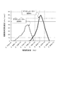
(駆動特性)
次に、図7に示す駆動装置100Aにおいて、試料Aと試料Bとの駆動特性を確認した。駆動装置100Aに対して、駆動電圧として±5Vの正弦波電流を投入し、被駆動体40Aの回転速度と、突起部20dにおける楕円振動の周波数との関係を測定し、図10の結果を得た。図10に示すように、入力電源(駆動電圧として±5Vの正弦波電流)に対して試料Aの方が試料Bより早い回転速度を得ることができる。
(Drive characteristics)
Next, in the driving apparatus 100A shown in FIG. 7, the driving characteristics of the sample A and the sample B were confirmed. A sine wave current of ± 5 V is applied as a driving voltage to the driving device 100A, and the relationship between the rotational speed of the driven
以上の通り、振動板20の長手方向Lを基材mの圧延ロール方向Rに交差させて形成する(図3参照)、すなわち振動板20の長手方向Lのヤング率を大きくすることにより駆動効率の高い圧電アクチュエーターを得ることができる。
As described above, the longitudinal direction L of the
10…圧電素子、20…振動板、100…圧電アクチュエーター。
DESCRIPTION OF
Claims (14)
前記振動板が前記被駆動手段を付勢する方向における前記振動板のヤング率ELと、前記付勢する方向に交差する方向における前記振動板のヤング率ESと、が異なる、
ことを特徴とする圧電アクチュエーター。 E Bei the vibration plate you urged to the driven means, and
And Young's modulus EL of the diaphragm in a direction in which the diaphragm urges the driven means, and the Young's modulus ES of the diaphragm in towards direction you intersecting the direction in which the urging, is different,
A piezoelectric actuator characterized by that.
ことを特徴とする請求項1に記載の圧電アクチュエーター。 The diaphragm includes a plate-shaped base material formed by a rolling process,
The piezoelectric actuator according to claim 1.
EL>ES
である、
ことを特徴とする請求項1または2に記載の圧電アクチュエーター。 The Young's modulus EL and the Young's modulus ES are
EL> ES
Is,
The piezoelectric actuator according to claim 1 or 2.
前記圧電体は、チタン酸ジルコン酸鉛(PZT)を含む、
ことを特徴とする請求項1から3のいずれか一項に記載の圧電アクチュエーター。 A piezoelectric body laminated on the diaphragm,
The piezoelectric body comprises a lead zirconate titanate (PZT),
The piezoelectric actuator according to any one of claims 1 to 3, wherein:
前記圧電アクチュエーターを前記被駆動手段に付勢する付勢手段と、を備える、
ことを特徴とするモーター。 The piezoelectric actuator according to any one of claims 1 to 4, and
The pre-Symbol piezoelectric actuator and a biasing means for biasing said driven means,
A motor characterized by that.
前記振動板は、前記第1の辺から突出し、かつ、被駆動部材と当接する突出部を有し、 The diaphragm has a protruding portion that protrudes from the first side and contacts the driven member,
前記第1の辺の中心と前記第2の辺の中心とを通る直線方向における前記振動板のヤング率ELと、前記第3の辺の中心と前記第4の辺の中心とを通る直線方向における前記振動板のヤング率ESと、が異なる、ことを特徴とする圧電アクチュエーター。 The Young's modulus EL of the diaphragm in a linear direction passing through the center of the first side and the center of the second side, and the linear direction passing through the center of the third side and the center of the fourth side The piezoelectric actuator according to claim 1, wherein the Young's modulus ES of the diaphragm is different.
ことを特徴とする請求項8に記載の圧電アクチュエーター。 The piezoelectric actuator according to claim 8.
EL>ES EL> ES
である、 Is,
ことを特徴とする請求項8または9に記載の圧電アクチュエーター。 The piezoelectric actuator according to claim 8 or 9, characterized in that.
前記圧電体は、チタン酸ジルコン酸鉛(PZT)を含む、 The piezoelectric body includes lead zirconate titanate (PZT).
ことを特徴とする請求項8から10のいずれか一項に記載の圧電アクチュエーター。 The piezoelectric actuator according to any one of claims 8 to 10, wherein:
前記圧電アクチュエーターを前記被駆動手段に付勢する付勢手段と、を備える、 Urging means for urging the piezoelectric actuator to the driven means,
ことを特徴とするモーター。 A motor characterized by that.
Priority Applications (3)
| Application Number | Priority Date | Filing Date | Title |
|---|---|---|---|
| JP2011073559A JP5776270B2 (en) | 2011-03-29 | 2011-03-29 | Piezoelectric actuators, motors, robot hands and robots |
| US13/431,047 US8525387B2 (en) | 2011-03-29 | 2012-03-27 | Piezoelectric actuator, motor, robot hand, and robot |
| US13/954,284 US8810109B2 (en) | 2011-03-29 | 2013-07-30 | Piezoelectric actuator, motor, robot hand, and robot |
Applications Claiming Priority (1)
| Application Number | Priority Date | Filing Date | Title |
|---|---|---|---|
| JP2011073559A JP5776270B2 (en) | 2011-03-29 | 2011-03-29 | Piezoelectric actuators, motors, robot hands and robots |
Publications (3)
| Publication Number | Publication Date |
|---|---|
| JP2012210052A JP2012210052A (en) | 2012-10-25 |
| JP2012210052A5 JP2012210052A5 (en) | 2014-04-03 |
| JP5776270B2 true JP5776270B2 (en) | 2015-09-09 |
Family
ID=46926204
Family Applications (1)
| Application Number | Title | Priority Date | Filing Date |
|---|---|---|---|
| JP2011073559A Active JP5776270B2 (en) | 2011-03-29 | 2011-03-29 | Piezoelectric actuators, motors, robot hands and robots |
Country Status (2)
| Country | Link |
|---|---|
| US (2) | US8525387B2 (en) |
| JP (1) | JP5776270B2 (en) |
Families Citing this family (14)
| Publication number | Priority date | Publication date | Assignee | Title |
|---|---|---|---|---|
| DE102013204026B4 (en) * | 2013-03-08 | 2019-08-08 | Physik Instrumente (Pi) Gmbh & Co. Kg | Actuator arrangement for an ultrasonic motor |
| JP6164044B2 (en) * | 2013-10-30 | 2017-07-19 | セイコーエプソン株式会社 | Piezoelectric motor, robot hand, robot, finger assist device, electronic component transport device, electronic component inspection device, liquid feed pump, printing device, electronic clock, projection device |
| JP6268999B2 (en) * | 2013-12-06 | 2018-01-31 | セイコーエプソン株式会社 | Piezoelectric motor, robot hand, robot, finger assist device, electronic component transport device, electronic component inspection device, liquid feed pump, printing device, electronic clock, projection device |
| KR102177156B1 (en) | 2014-03-10 | 2020-11-10 | 삼성전자주식회사 | robot and substrate processing apparatus including the same |
| USD751044S1 (en) * | 2014-05-22 | 2016-03-08 | Hzo, Inc. | Control switch for an electronic device |
| CN105375812A (en) | 2014-08-13 | 2016-03-02 | 精工爱普生株式会社 | Piezoelectric driving device and driving method therefor, and robot and driving method therefor |
| JP6398454B2 (en) * | 2014-08-13 | 2018-10-03 | セイコーエプソン株式会社 | Piezoelectric drive device, robot, and drive method thereof |
| JP6543896B2 (en) * | 2014-08-13 | 2019-07-17 | セイコーエプソン株式会社 | Piezoelectric drive device, robot, and method of driving them |
| JP6467809B2 (en) * | 2014-08-13 | 2019-02-13 | セイコーエプソン株式会社 | Piezoelectric driving device and driving method thereof, robot and driving method thereof |
| JP6503764B2 (en) * | 2015-02-02 | 2019-04-24 | セイコーエプソン株式会社 | Piezoelectric element drive circuit and robot |
| JP2017017916A (en) * | 2015-07-03 | 2017-01-19 | セイコーエプソン株式会社 | Piezoelectric driving device, robot, and driving method of piezoelectric driving device |
| JP6641944B2 (en) * | 2015-12-03 | 2020-02-05 | セイコーエプソン株式会社 | Piezoelectric drive device for motor and method of manufacturing the same, motor, robot, and pump |
| JP7035358B2 (en) * | 2017-07-28 | 2022-03-15 | セイコーエプソン株式会社 | Piezoelectric drive device, drive method of piezoelectric drive device, and robot |
| CN112161765B (en) * | 2020-09-01 | 2021-08-20 | 大连理工大学 | Contact interface tangential rigidity testing device under cyclic load based on piezoelectric actuator |
Family Cites Families (14)
| Publication number | Priority date | Publication date | Assignee | Title |
|---|---|---|---|---|
| JPS5683983A (en) * | 1979-12-12 | 1981-07-08 | Sony Corp | Electricity-machinery conversion element |
| JPS59188381A (en) | 1983-04-06 | 1984-10-25 | Shinsei Kogyo:Kk | Improvement in rotor/movable element of surface wave motor |
| JP3167432B2 (en) | 1992-07-16 | 2001-05-21 | キヤノン株式会社 | Vibration wave drive device and device equipped with vibration wave drive device |
| CN100367649C (en) * | 1998-12-21 | 2008-02-06 | 精工爱普生株式会社 | Piezoelectric actuator and timepiece |
| JP2001286167A (en) | 2000-03-30 | 2001-10-12 | Seiko Epson Corp | Adjustment method of piezoelectric actuator and piezoelectric actuator |
| JP2003159566A (en) | 2001-11-27 | 2003-06-03 | Matsushita Electric Ind Co Ltd | Ultrasonic vibrator, driver and heater |
| JP2004166479A (en) * | 2002-06-14 | 2004-06-10 | Seiko Epson Corp | Rotary drive device and apparatus equipped with same |
| JP2004159403A (en) | 2002-11-05 | 2004-06-03 | Seiko Epson Corp | Piezoelectric actuator |
| JP4370854B2 (en) | 2003-08-21 | 2009-11-25 | セイコーエプソン株式会社 | Piezoelectric actuator and device provided with the same |
| JP2005086991A (en) | 2003-09-11 | 2005-03-31 | Seiko Epson Corp | Piezo-electric actuator, motor, and apparatus equipped with piezo-electric actuator |
| JP4857886B2 (en) * | 2005-06-24 | 2012-01-18 | セイコーエプソン株式会社 | Shock-resistant device for piezoelectric actuator and electronic device equipped with the same |
| JP2007221865A (en) * | 2006-02-14 | 2007-08-30 | Seiko Epson Corp | Piezoelectric vibrator, adjusting method for natural frequency of piezoelectric vibrator, piezoelectric actuator, and electronic apparatus |
| JP4465397B2 (en) * | 2008-05-12 | 2010-05-19 | シャープ株式会社 | Ultrasonic motor |
| JP2010233335A (en) | 2009-03-26 | 2010-10-14 | Seiko Epson Corp | Piezoelectric motor, liquid jetting device, and timepiece |
-
2011
- 2011-03-29 JP JP2011073559A patent/JP5776270B2/en active Active
-
2012
- 2012-03-27 US US13/431,047 patent/US8525387B2/en active Active
-
2013
- 2013-07-30 US US13/954,284 patent/US8810109B2/en active Active
Also Published As
| Publication number | Publication date |
|---|---|
| US8810109B2 (en) | 2014-08-19 |
| US20130313945A1 (en) | 2013-11-28 |
| US20120248805A1 (en) | 2012-10-04 |
| US8525387B2 (en) | 2013-09-03 |
| JP2012210052A (en) | 2012-10-25 |
Similar Documents
| Publication | Publication Date | Title |
|---|---|---|
| JP5776270B2 (en) | Piezoelectric actuators, motors, robot hands and robots | |
| JP4052249B2 (en) | Rotation / movement conversion actuator | |
| JP5765993B2 (en) | Vibration type driving device | |
| US20120279342A1 (en) | Motor, robot hand, and robot | |
| JP2004320979A (en) | Driving device and electric equipment | |
| CN101674029A (en) | Vibration wave driving device | |
| JP4222208B2 (en) | Piezoelectric actuator, timepiece including piezoelectric actuator, and portable device | |
| JP3719061B2 (en) | Piezoelectric actuators, watches and portable devices | |
| JP2013207978A (en) | Piezoelectric motor, robot hand and robot | |
| US20120308355A1 (en) | Motor, robot hand, and robot | |
| JP2004320980A (en) | Driving device and electric equipment | |
| US7825566B2 (en) | Ultrasonic actuator and method for manufacturing piezoelectric deformation portion used in the same | |
| JP2015186329A (en) | piezoelectric motor | |
| JP2012210053A (en) | Piezoelectric actuator, robot, and robot hand | |
| JP3632562B2 (en) | Piezoelectric actuators, watches and portable devices | |
| JP5803294B2 (en) | Motor, robot hand and robot | |
| EP2290720B1 (en) | Ultrasonic motor | |
| JP2008178209A (en) | Ultrasonic actuator | |
| JP2001286167A (en) | Adjustment method of piezoelectric actuator and piezoelectric actuator | |
| JP4631124B2 (en) | Piezoelectric actuators, watches and equipment | |
| JP3721928B2 (en) | Piezoelectric actuators, watches and portable devices | |
| JP3680602B2 (en) | Piezoelectric actuators, watches and portable devices | |
| JP2004312814A (en) | Operation device and electric apparatus | |
| JP2004242493A (en) | Piezoelectric actuator and electronic device using the same | |
| CN116260359A (en) | Piezoelectric driving device and robot |
Legal Events
| Date | Code | Title | Description |
|---|---|---|---|
| A521 | Request for written amendment filed |
Free format text: JAPANESE INTERMEDIATE CODE: A523 Effective date: 20140214 |
|
| A621 | Written request for application examination |
Free format text: JAPANESE INTERMEDIATE CODE: A621 Effective date: 20140214 |
|
| A977 | Report on retrieval |
Free format text: JAPANESE INTERMEDIATE CODE: A971007 Effective date: 20141009 |
|
| A131 | Notification of reasons for refusal |
Free format text: JAPANESE INTERMEDIATE CODE: A131 Effective date: 20141021 |
|
| RD04 | Notification of resignation of power of attorney |
Free format text: JAPANESE INTERMEDIATE CODE: A7424 Effective date: 20150106 |
|
| TRDD | Decision of grant or rejection written | ||
| A01 | Written decision to grant a patent or to grant a registration (utility model) |
Free format text: JAPANESE INTERMEDIATE CODE: A01 Effective date: 20150609 |
|
| A61 | First payment of annual fees (during grant procedure) |
Free format text: JAPANESE INTERMEDIATE CODE: A61 Effective date: 20150622 |
|
| R150 | Certificate of patent or registration of utility model |
Ref document number: 5776270 Country of ref document: JP Free format text: JAPANESE INTERMEDIATE CODE: R150 |
|
| S531 | Written request for registration of change of domicile |
Free format text: JAPANESE INTERMEDIATE CODE: R313531 |
|
| R350 | Written notification of registration of transfer |
Free format text: JAPANESE INTERMEDIATE CODE: R350 |