JP4465397B2 - Ultrasonic motor - Google Patents
Ultrasonic motor Download PDFInfo
- Publication number
- JP4465397B2 JP4465397B2 JP2008124843A JP2008124843A JP4465397B2 JP 4465397 B2 JP4465397 B2 JP 4465397B2 JP 2008124843 A JP2008124843 A JP 2008124843A JP 2008124843 A JP2008124843 A JP 2008124843A JP 4465397 B2 JP4465397 B2 JP 4465397B2
- Authority
- JP
- Japan
- Prior art keywords
- ultrasonic
- ultrasonic transducer
- rotor
- ultrasonic motor
- preload
- Prior art date
- Legal status (The legal status is an assumption and is not a legal conclusion. Google has not performed a legal analysis and makes no representation as to the accuracy of the status listed.)
- Expired - Fee Related
Links
Images


Classifications
-
- H—ELECTRICITY
- H02—GENERATION; CONVERSION OR DISTRIBUTION OF ELECTRIC POWER
- H02N—ELECTRIC MACHINES NOT OTHERWISE PROVIDED FOR
- H02N2/00—Electric machines in general using piezoelectric effect, electrostriction or magnetostriction
- H02N2/10—Electric machines in general using piezoelectric effect, electrostriction or magnetostriction producing rotary motion, e.g. rotary motors
- H02N2/103—Electric machines in general using piezoelectric effect, electrostriction or magnetostriction producing rotary motion, e.g. rotary motors by pressing one or more vibrators against the rotor
-
- H—ELECTRICITY
- H02—GENERATION; CONVERSION OR DISTRIBUTION OF ELECTRIC POWER
- H02N—ELECTRIC MACHINES NOT OTHERWISE PROVIDED FOR
- H02N2/00—Electric machines in general using piezoelectric effect, electrostriction or magnetostriction
- H02N2/0005—Electric machines in general using piezoelectric effect, electrostriction or magnetostriction producing non-specific motion; Details common to machines covered by H02N2/02 - H02N2/16
- H02N2/001—Driving devices, e.g. vibrators
- H02N2/003—Driving devices, e.g. vibrators using longitudinal or radial modes combined with bending modes
- H02N2/004—Rectangular vibrators
-
- H—ELECTRICITY
- H02—GENERATION; CONVERSION OR DISTRIBUTION OF ELECTRIC POWER
- H02N—ELECTRIC MACHINES NOT OTHERWISE PROVIDED FOR
- H02N2/00—Electric machines in general using piezoelectric effect, electrostriction or magnetostriction
- H02N2/0005—Electric machines in general using piezoelectric effect, electrostriction or magnetostriction producing non-specific motion; Details common to machines covered by H02N2/02 - H02N2/16
- H02N2/005—Mechanical details, e.g. housings
- H02N2/0055—Supports for driving or driven bodies; Means for pressing driving body against driven body
Landscapes
- General Electrical Machinery Utilizing Piezoelectricity, Electrostriction Or Magnetostriction (AREA)
Description
本発明は、超音波モータに関するものである。 The present invention relates to an ultrasonic motor.
PZT(チタン酸ジルコニウム酸鉛)等の圧電素子は、単位体積あたりの蓄積可能な機械的エネルギーが大きく、これを用いて小型・ハイパワーなアクチュエータが実用化されている。これらは一般に超音波モータと称されている。ここで、共振型の超音波モータの基本動作について説明する。 Piezoelectric elements such as PZT (lead zirconate titanate) have large mechanical energy that can be stored per unit volume, and small and high-power actuators have been put to practical use by using this. These are generally called ultrasonic motors. Here, the basic operation of the resonance type ultrasonic motor will be described.
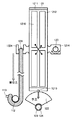
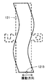
圧電素子に、共振周波数を一致させた複数の振動モードを励起することで楕円運動を得て、摩擦により被駆動体を移動させるタイプの超音波モータが古くから研究されている。たとえば、図10は、特許文献1(特開2007−106393号公報)に記載されている超音波モータを示す。図11に、特許文献1に開示された超音波振動子121の詳細を示す。
For a long time, an ultrasonic motor that obtains an elliptical motion by exciting a plurality of vibration modes having the same resonance frequency to a piezoelectric element and moves a driven body by friction has been studied. For example, FIG. 10 shows an ultrasonic motor described in Patent Document 1 (Japanese Patent Laid-Open No. 2007-106393). FIG. 11 shows details of the
この超音波振動子121は、補強用のステンレス板1211を2枚の圧電素子1212、1213で挟み込んだ上下鏡面対称の構造を有している。矩形状平板の超音波振動子121について、図12に示される面内方向における1次の伸び縮み振動モード、および図13に示される面内方向における2次のたわみ振動モードについて略同一の共振周波数を有している。
This
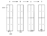
圧電素子1212、1213の上には、それぞれ4分割された電極1216、1217が配されている。電極1216、1217の対角に位置する電極は、それぞれ結線されている。この2組の電極に、互いに位相が90°異なる交番電圧、φA、φBを印加する。
On the
これにより、図14中のA→B→C→Dの順で示されるように、上記の両振動モードが位相を90°異なって励起される。これにより、超音波振動子121の先端部に楕円運動が生じる。この先端部を被駆動部に押し当てれば、摩擦力により被駆動部が運ばれる。なお、この押し当てる力は一般的に予圧(preload)と呼ばれる。
Thereby, as shown in the order of A → B → C → D in FIG. 14, the two vibration modes are excited with a phase difference of 90 °. Thereby, an elliptical motion is generated at the tip of the
この予圧を与える手法として、特許文献1では、図10に示すように、シャフト127を中心に回転する耳軸1214を用いて超音波振動子121を保持し、その対向する側面に設けられた被牽引部1224を、ポール112に巻き付けられた弾性体129により牽引する構成が提案されている。また、ステンレス板1211の頂点にはセラミックからなる接触部1215が設けられ、扇型のロータ122は、ベアリング123を介して、ロータシャフト124に、ロータシャフト124の軸周りにのみ回転可能に設けられている。
As a technique for applying this preload, in Patent Document 1, as shown in FIG. 10, an
また、非特許文献1には、内接型超音波モータが開示されている。その構造を図15に示す。超音波振動子21を2つ用いた、4点接触タイプの超音波モータである。これは前記の構成と同様の超音波振動子21および22を、中央のパンタグラフ型予圧機構3により、その頂点部を円筒型ロータ1に、予圧を持って内接させた構成を有する。
Non-Patent Document 1 discloses an inscribed ultrasonic motor. The structure is shown in FIG. This is a four-point contact type ultrasonic motor using two
図16に示すように、各頂点Pは楕円運動の軌道を描くことにより、全ての頂点Pにおいて、同一方向への駆動力を得ることができる。また、非特許文献1には、同様の振動モードを用いる、扇形超音波振動子を用いた4点接触タイプのモータが記されている。これらは、内側から超音波振動子を被駆動部に押し当てるため、上記発明に代表される、ロータの外側から超音波振動子を駆動するタイプのモータに比べて以下のメリットがある。 As shown in FIG. 16, each vertex P draws an orbit of elliptical motion, so that a driving force in the same direction can be obtained at all the vertexes P. Non-Patent Document 1 describes a four-point contact type motor using a fan-shaped ultrasonic transducer that uses a similar vibration mode. These press the ultrasonic transducer against the driven part from the inside, and therefore have the following merits compared to a motor of the type that drives the ultrasonic transducer from the outside of the rotor represented by the above invention.
超音波モータは摩擦力により被駆動体を駆動するため、大きい駆動トルクを得るには予圧を高める必要がある。しかし超音波モータの動作原理上、過剰に予圧を掛けると、楕円運動の全周に渡って、超音波振動子が被駆動部と接触する状態となり、駆動効率の低下が生じる。このため、印加可能な予圧には上限があり、ひいては、これがトルクの上限を決めている。また、大きい予圧は接点領域の摩耗を増長し、モータの寿命を縮めてしまう。 Since the ultrasonic motor drives the driven body by frictional force, it is necessary to increase the preload to obtain a large driving torque. However, if the preload is excessively applied due to the operation principle of the ultrasonic motor, the ultrasonic vibrator is brought into contact with the driven part over the entire circumference of the elliptical motion, resulting in a decrease in driving efficiency. For this reason, there is an upper limit to the preload that can be applied, which in turn determines the upper limit of the torque. A large preload also increases the wear of the contact area and shortens the life of the motor.
しかし、図16に示すように4点接触型の内接型超音波モータによれば、4点で摩擦力が得られる。更に、被駆動体が同一であれば、モータのトルクはこれらを合算したものとなるため、同じ予圧においても最大4倍のトルクを得ることが可能になる。また逆に同一のトルクであれば予圧が1/4で済むので接点領域の摩耗が抑えられ、モータの長寿命化に繋がる。 However, as shown in FIG. 16, according to the four-point contact type inscribed ultrasonic motor, a friction force can be obtained at four points. Further, if the driven bodies are the same, the torque of the motor is the sum of these, so that it is possible to obtain a maximum of four times the torque even with the same preload. On the other hand, if the torque is the same, the preload can be reduced to ¼, so that the wear of the contact area can be suppressed and the life of the motor can be extended.
また、ロータの内側に超音波振動子が配されているので、同一径のロータを用いた場合、設置面積の低減が可能である。また、超音波振動子を保持する構成要素と、ロータを保持する構成要素が共有されているので、部品点数を削減することができる。 In addition, since the ultrasonic transducer is arranged inside the rotor, the installation area can be reduced when a rotor having the same diameter is used. In addition, since the component that holds the ultrasonic transducer and the component that holds the rotor are shared, the number of components can be reduced.
なお、図17に示された超音波モータにおいては、扇形の超音波振動子を用いている。基本的に用いる振動モードは類似であるが、超音波振動子21aおよび22bのロータ1との接点における楕円運動の一つの軸が、ロータ1の接線方向と一致している。このため、矩形の超音波振動子を用いた場合に比べ大きい振幅を得ることができ、駆動の効率が向上させることができる。
しかし、実際の超音波モータの製作においては必ず加工誤差が伴う。特許文献2に開示される図16の構成において4点の接触を得ることは難しく、3点での接触、すなわち一つの超音波振動子の両端と、もう一つの超音波振動子の片側どちらかの接触となるという問題があった。これにより、所望の性能が発揮できないという問題があった。 However, machining errors are always involved in the production of an actual ultrasonic motor. In the configuration of FIG. 16 disclosed in Patent Document 2, it is difficult to obtain contact at four points, ie contact at three points, that is, either one end of one ultrasonic transducer and one side of another ultrasonic transducer. There was a problem of becoming contact. Thereby, there existed a problem that desired performance could not be exhibited.
以下、具体的に説明する。なお、以下の説明および図においては、説明の簡便のため、2次元平面内にて説明を行ない、超音波振動子の形状は外形線のみで表す。また、超音波振動子形状は矩形であるものとするが、上記の扇形についても同様である。更に、超音波振動子を保持し、ロータに押しつける機構は機能のみ問題であるので抽象的にピストンの記号を用いて記載する。 This will be specifically described below. In the following description and drawings, the description will be made in a two-dimensional plane for convenience of description, and the shape of the ultrasonic transducer is represented only by the outline. Moreover, although the ultrasonic transducer | vibrator shape shall be a rectangle, it is the same also about said fan shape. Furthermore, since the mechanism for holding the ultrasonic transducer and pressing it against the rotor is only a function problem, it is described abstractly using a piston symbol.
図18を参照して説明する。2つの超音波振動子21,22を用いて、ロータ1を駆動するものとする。ロータ1は真円であるものとする。2つの超音波振動子21,22は、間に介在するパンタグラフ型予圧機構3によりロータ1に内接させられている。
This will be described with reference to FIG. It is assumed that the rotor 1 is driven using two
図18に示すように、図示において、左側の超音波振動子21がロータ1に内接しているものとする。予圧機構3により、右側の超音波振動子22は左側の超音波振動子21に対してその距離を変えることができる。このため、右側の超音波振動子22においても1点はロータ1に内接することが可能である。もう1つの超音波振動子21もロータ1に内接する。超音波振動子21および22が理想的に矩形をしており、かつ、これらが平行に配されているなら、4点での接触が可能となる。
As shown in FIG. 18, in the drawing, it is assumed that the left
しかし、図19に示したように、実際には超音波振動子の形状には加工誤差が避けられず、厳密に矩形でない場合が殆どである。また、接点の摩耗などの後発的な事象によっても超音波振動子の形状のずれは起こり得る。 However, as shown in FIG. 19, in reality, machining errors are unavoidable in the shape of the ultrasonic transducer, and in most cases, the shape is not strictly rectangular. Further, the shape of the ultrasonic transducer may be displaced by a subsequent event such as contact wear.
その結果、図19に示されるように、どちらか1つの点のみがロータ1に接し、もう1つの点は図19に示されたギャップdだけ離れている状態となる。このため、上記加工誤差による位置ずれが大きい場合、この点が楕円運動を行っても、ロータ1に接することがないため、期待される摩擦力を得ることができない場合が生じる。 As a result, as shown in FIG. 19, only one of the points is in contact with the rotor 1, and the other point is separated by the gap d shown in FIG. For this reason, when the positional deviation due to the processing error is large, even if this point performs an elliptical motion, it does not contact the rotor 1, so that the expected frictional force may not be obtained.
これを解消するには、ギャップdが上記超音波振動子22の接点における楕円運動の振幅より小さい範囲に維持できるだけの加工誤差が必要である。しかし一般的には、この楕円運動の振幅はサブミクロンオーダーであり、加工精度はこれよりさらに小さいことが要求される。これは、機械加工などの通常の加工方法では極めて達成が困難な範囲である。
In order to eliminate this, a machining error that can maintain the gap d in a range smaller than the amplitude of the elliptical motion at the contact point of the
以上より、上記構成の超音波モータは、期待されるトルクの3/4までのトルクしか得られないことになる。更に実際には、1点のみ接触している側の超音波振動子について言えば、予圧がこの接触している1点に集中しており、対向する超音波振動子における予圧の2倍となる。このため、トルク、摩耗について、期待される上記の数値よりも更に悪化することが懸念される。 From the above, the ultrasonic motor having the above configuration can obtain only torque that is up to 3/4 of the expected torque. Furthermore, in practice, in the case of the ultrasonic transducer on the side that is in contact with only one point, the preload is concentrated at this point in contact, which is twice the preload in the opposing ultrasonic transducer. . For this reason, there is a concern that the torque and wear may be further deteriorated from the above-described numerical values.
本発明の目的は、背景技術における上記の課題に鑑み、安定して4点全てが内接することが可能な超音波振動子の構成を有する超音波モータを提供することにある。 An object of the present invention is to provide an ultrasonic motor having a configuration of an ultrasonic transducer that can stably inscribe all four points in view of the above-described problems in the background art.
本発明に基づいた超音波モータにおいては、機械的出力を行なう円筒状ロータと、上記ロータに内接する2頂点を有する複数の超音波振動子と、上記超音波振動子を、上記ロータの内側から外側に向けて押しつける予圧機構を含み、上記超音波振動子は、上記超音波振動子を含む平面内において、上記予圧機構に対して回動可能に設けられている。1自由度回動の自由度が加わることで、4点以上の内接が、加工誤差があっても可能になる。 In the ultrasonic motor according to the present invention, a cylindrical rotor that performs mechanical output, a plurality of ultrasonic transducers having two vertices inscribed in the rotor, and the ultrasonic transducer are arranged from the inside of the rotor. The ultrasonic transducer includes a preload mechanism that presses outward, and the ultrasonic transducer is provided so as to be rotatable with respect to the preload mechanism in a plane including the ultrasonic transducer. By adding the degree of freedom of one degree of freedom rotation, it is possible to inscribe four or more points even if there is a machining error.
また、本発明に基づいた超音波モータにおいては、上記回動可能部位が、上記超音波振動子の振動の節に位置する。この構成により、予圧の大小が超音波振動子の駆動に悪影響を及ぼさない構成が実現する。 In the ultrasonic motor according to the present invention, the rotatable portion is located at a vibration node of the ultrasonic transducer. With this configuration, a configuration in which the magnitude of the preload does not adversely affect the driving of the ultrasonic transducer is realized.
また、本発明に基づいた超音波モータにおいては、上記超音波振動子は、その振動の節に貫通穴を有し、この貫通穴に通されたシャフトを用いて、上記予圧機構に対して回動可能に保持されている。この構成により、超音波振動子の駆動にほぼ悪影響を与えることなく、振動の節での保持が可能になる。 In the ultrasonic motor according to the present invention, the ultrasonic vibrator has a through hole at a node of the vibration, and is rotated with respect to the preload mechanism by using a shaft passed through the through hole. It is held movable. With this configuration, the vibration can be held at a node without substantially adversely affecting the driving of the ultrasonic transducer.
また、本発明に基づいた超音波モータにおいては、上記超音波振動子は平面形状が長方形であり、上記ロータにはその長辺側面を向けて配されており、上記予圧機構は、その一部が、上記長辺側面に対向する側面の略中央部を押圧する。 Further, in the ultrasonic motor according to the present invention, the ultrasonic vibrator has a rectangular planar shape, and is arranged with the long side surface facing the rotor, and the preload mechanism includes a part thereof. However, the substantially center part of the side surface facing the said long side surface is pressed.
上記の構成により、より超音波振動子に対する加工工程が少なく、性能劣化の懸念がより少ない超音波モータを得ることが可能となる。 With the above configuration, it is possible to obtain an ultrasonic motor with fewer processing steps for the ultrasonic vibrator and less concern about performance deterioration.
本発明に基づいた超音波モータによれば、従来の内接型超音波モータの欠点を改善し、4点以上の接点で駆動することのできる、駆動効率の良い、寿命の長い超音波モータを提供することが可能となる。 According to the ultrasonic motor according to the present invention, an ultrasonic motor with improved driving efficiency and long life that can be driven by four or more contacts is improved. It becomes possible to provide.
以下に、本発明の実施の形態に基づいた超音波モータの構造について説明する。なお、同一または相当する部分に同一の参照符号を付し、その説明を繰り返さない場合がある。 The structure of the ultrasonic motor based on the embodiment of the present invention will be described below. In addition, the same reference number is attached | subjected to the part which is the same or it corresponds, and the description may not be repeated.
また、以下に説明する実施の形態において、個数、量などに言及する場合、特に記載がある場合を除き、本発明の範囲は必ずしもその個数、量などに限定されない。 In the embodiments described below, when referring to the number, amount, and the like, the scope of the present invention is not necessarily limited to the number, amount, and the like unless otherwise specified.
また、本発明における超音波モータは、超音波振動子とロータの配置および摩擦力のやりとりに関わるものであり、2つの超音波振動子が2点で円筒型ロータに内接して駆動する態様の超音波モータであれば適用可能である。よって、本実施の形態に記載の構成は一例であり、たとえば超音波振動子の形状などはこれに限るものではない。たとえば、図19に示されるような、扇形超音波振動子を用いたものであっても、同様に適用可能である。 The ultrasonic motor according to the present invention relates to the arrangement of the ultrasonic vibrator and the rotor and the exchange of the frictional force, and the two ultrasonic vibrators are driven in contact with the cylindrical rotor at two points. Any ultrasonic motor can be used. Therefore, the configuration described in the present embodiment is an example, and the shape of the ultrasonic transducer is not limited to this, for example. For example, even the one using a fan-shaped ultrasonic transducer as shown in FIG. 19 can be similarly applied.
(実施の形態1)
図1から図4を参照して、実施の形態1における超音波モータの構成について説明する。なお、図1は、この発明の実施の形態1における超音波モータの全体斜視図であり、図2は、この発明の実施の形態1における超音波モータの分解斜視図である。また、図3は、この発明の実施の形態1における超音波モータの4点接触を説明する模式図であり、図4は、この発明の実施の形態1における超音波モータの他の形態を示す平面模式図である。円筒形状のロータ1に、2つの超音波振動子21および22が、それぞれ、接点211、212(図示省略)、および接点221、222を介して内接している。
(Embodiment 1)
The configuration of the ultrasonic motor according to the first embodiment will be described with reference to FIGS. 1 is an overall perspective view of the ultrasonic motor according to Embodiment 1 of the present invention, and FIG. 2 is an exploded perspective view of the ultrasonic motor according to Embodiment 1 of the present invention. FIG. 3 is a schematic diagram for explaining the four-point contact of the ultrasonic motor according to the first embodiment of the present invention. FIG. 4 shows another form of the ultrasonic motor according to the first embodiment of the present invention. It is a plane schematic diagram. Two
超音波振動子21および22は、予圧機構3により、ロータ1に対して、外側に押し広げられる形で押しつけられている。超音波振動子21は、上記にて説明されているφA、φBに、位相を90°異ならせて加えられた交番電圧により、図16を用いて説明したような楕円運動を行なう。
The
超音波振動子22は、これに対して鏡面対称の電極配置を有する構成をとっており、上記にて説明されているφA、φBに、位相を90°異ならせて加えられた交番電圧により、図16を用いて説明したような楕円運動を行なう。すなわち、ロータ1に内接する全ての接点が、ロータ1を同一方向(図16においては時計回り)に回転させる楕円運動を行なう。
The
(予圧機構および超音波振動子保持機構)
図2を参照して、予圧機構および超音波振動子保持機構について説明する。超音波振動子21および22は、それぞれその中央に、貫通穴213および223が設けられている。この穴に、シャフト31および32が通され、予圧機構3における、上部パンタグラフ33および下部パンタグラフ34が、それぞれこのシャフトの上下端を保持している。
(Preload mechanism and ultrasonic vibrator holding mechanism)
With reference to FIG. 2, the preload mechanism and the ultrasonic transducer holding mechanism will be described. The
上部パンタグラフ33および下部パンタグラフ34は、調整ネジ35によりその間隔が可変であり、間隔を縮めた際はこのパンタグラフが広がる。更に、超音波振動子21および22とロータが接している状態であれば、ロータ1に対する予圧が高まる。逆に、間隔を広げた際には予圧が小さくなる。
The interval between the
シャフト31および32と、超音波振動子21および22における貫通穴213および223は円形の略同一断面形状を有するので、超音波振動子21および22は、その貫通穴を中心として回動可能である。なお、原理的には、双方の超音波振動子21および22が回動可能であることは必須ではなく、どちらか一方のみ回動可能であれば本発明の要件は満たされている。
Since the
余分な可動部は、ガタなどで超音波モータの性能悪化の一因となり得るため、排除されるのが好ましい場合がある。この場合、超音波振動子21および22どちらかの貫通穴がシャフトに接着されていればよい。逆に、モータの対称性が良い方が、設計外の振動を生じる可能性が減るため、超音波振動子21および22の双方が同様の保持条件である方が良い場合もある。
Excessive movable parts may be a cause of deterioration of the performance of the ultrasonic motor due to play or the like, and may be preferably eliminated. In this case, the through hole of either the
(4点接触となる原理)
図3を参照して、4点接触となる原理について説明する。図3に示された、超音波振動子22における片方の頂点のみロータ1に接している状態で、予圧機構3を用いて、両超音波振動子間距離をさらに広げる。超音波振動子22は平面形状が長方形であり、ロータ1にはその長辺側面を向けて配されており、予圧機構3は、その一部が、長辺側面に対向する側面の略中央部を押圧する。
(Principle of four-point contact)
With reference to FIG. 3, the principle of four-point contact will be described. In the state where only one vertex of the
超音波振動子22が、シャフト32を中心にして、超音波振動子22を含む平面内において回動することにより、両頂点の接触が実現する。この際、シャフト32を中心とした回動は、予圧機構3の押し広げ動作に伴い受動的に行われるので、何ら特別な作業を行なうことなく本発明に記された機能が実現できる。
The
(振動モードへの影響)
貫通穴213および223には、ロータ1の外側へ向けての圧力が加えられているため、超音波振動子21および22における振動を阻害するおそれがある。そこで、上述した図2に示した貫通穴213、223は、2つの振動モードの節であり、振動が最も小さい部位である、超音波振動子21および22の中心に設けられている。この構成により、貫通穴近辺は殆ど振動しないので、この部位を用いてシャフト31および32により超音波振動子21および22を拘束した際の影響は最低限に留められる。
(Influence on vibration mode)
Since pressure toward the outside of the rotor 1 is applied to the through
(超音波振動子の形状)
本実施の形態では、説明の簡便のため超音波振動子形状を矩形であるとした。しかし、本発明の本質は、現実的に実現困難であった円筒状ロータへの4点での内接を、超音波振動子に新たに1つの回転自由度を加えたことにより、具現化した点にある。すなわち、4点以上で内接することを所望する全ての超音波モータについて適用可能な発明である。たとえば、図17に示されるような扇形形状の超音波振動子を用いた超音波モータについても、同様の効果が得られる。
(Shape of ultrasonic transducer)
In the present embodiment, the shape of the ultrasonic transducer is assumed to be rectangular for ease of explanation. However, the essence of the present invention is realized by adding one degree of freedom to the ultrasonic transducer to inscribe four points in the cylindrical rotor that was difficult to realize in practice. In the point. That is, the invention can be applied to all ultrasonic motors that are desired to be inscribed at four or more points. For example, the same effect can be obtained for an ultrasonic motor using a fan-shaped ultrasonic transducer as shown in FIG.
さらに、1自由度でロータの半径方向に伸縮する機構と、これに1自由度回動可能な機構を介して保持される超音波振動子の組み合わせであれば、超音波振動子の個数についても、図4に示すように、予圧機構3によりそれぞれ外側に予圧される3つの超音波振動子321,322および323を有する超音波モータや、4以上の超音波振動子を含む超音波モータの採用も可能である。
Further, if the combination of a mechanism that expands and contracts in the radial direction of the rotor with one degree of freedom and an ultrasonic vibrator that is held by a mechanism that can be rotated by one degree of freedom, the number of ultrasonic vibrators as shown in FIG. 4, three being preloaded outside respectively by the
(予圧機構の形状)
同様に、予圧を与えるパンタグラフ型予圧機構3についても、2つの超音波振動子に、ロータ1の外側に向けて圧力を加える役割を果たす構成要素が、超音波振動子に設けられた回動可能な回転軸を保持している形態であれば、その構成、仕組みに関係なく、本発明の効果は得られるものと捉えられるべきである。
(Preload mechanism shape)
Similarly, in the pantograph
(ロータ)
ロータについても、本実施の形態に記されたものに限定されない。たとえばロータ脱落防止のための溝がロータ1の内部に設けられている構成の採用も可能である。さらに、回転体でなく矩形の溝を用いた超音波モータであっても本発明は同様に適用できる。
(Rotor)
The rotor is not limited to that described in the present embodiment. For example, it is possible to adopt a configuration in which a groove for preventing the rotor from falling off is provided inside the rotor 1. Furthermore, the present invention can be similarly applied even to an ultrasonic motor using a rectangular groove instead of a rotating body.
(実施の形態2)
図5から図9を参照して、実施の形態2における超音波モータの構成について説明する。なお、説明の簡便のため、上記実施の形態と同じ構成要素については同一番号を付し、その説明を繰り返さない。また、図5は、この発明の実施の形態2における超音波モータの全体斜視図であり、図6は、この発明の実施の形態2における超音波モータの分解斜視図であり、図7は、この発明の実施の形態2における超音波モータに採用される超音波振動子保持部の構造を示す模式図である。また、図8は、この発明の実施の形態2における超音波モータに採用される超音波振動子保持部の他の構造を示す模式図であり、図9は、この発明の実施の形態2における超音波モータに採用される超音波振動子保持部のさらに他の構造を示す模式図である。
(Embodiment 2)
The configuration of the ultrasonic motor according to the second embodiment will be described with reference to FIGS. For simplicity of explanation, the same components as those in the above embodiment are given the same numbers, and the description thereof will not be repeated. 5 is an overall perspective view of the ultrasonic motor according to Embodiment 2 of the present invention, FIG. 6 is an exploded perspective view of the ultrasonic motor according to Embodiment 2 of the present invention, and FIG. It is a schematic diagram which shows the structure of the ultrasonic transducer | vibrator holding | maintenance part employ | adopted as the ultrasonic motor in Embodiment 2 of this invention. FIG. 8 is a schematic diagram showing another structure of the ultrasonic transducer holding portion employed in the ultrasonic motor according to the second embodiment of the present invention, and FIG. 9 shows the structure according to the second embodiment of the present invention. It is a schematic diagram which shows other structure of the ultrasonic transducer | vibrator holding | maintenance part employ | adopted as an ultrasonic motor.
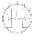
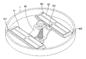
(全体の構成)
図5および図6に示すように、超音波振動子41および42は、突起431を有するパンタグラフ型予圧機構43によって、ロータ1の外側に押し広げられる構成を有し、ロータ1に内接している。その他は実施の形態1と同様である。
(Overall configuration)
As shown in FIGS. 5 and 6, the
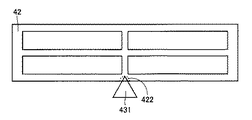
(超音波振動子)
超音波振動子41および42は鏡面対称であるので、以下、超音波振動子42のみについて、図7を参照して説明する。超音波振動子42は、その側面中央部に凹み421を有する。これにより、組み立ての際に突起431の、超音波振動子42に対する位置を定めることができる。また、超音波振動子42に外力が加わった際、突起431の、超音波振動子42に対する位置がずれるのを防ぐことができる。
(Ultrasonic transducer)
Since the
このように、突起431は、超音波振動子42と線接触をしているため、超音波振動子42はその接触線を回転中心とする回動運動を行なうことができる。また、線接触であるので、面外方向へ超音波振動子42が倒れることも防止できる。
Thus, since the
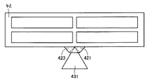
突起431が設けられる位置は、背景技術において説明した、2つの振動モードの共振周波数の一致が可能であれば、図8に示されるように、超音波振動子42そのものに設けられた凹み422でも構わない。また、より確実に超音波振動子の倒れを防止するため、図9に示されるように、突起431を上下から挟み込む一対のカバー423を設けることも可である。
As long as the resonance frequencies of the two vibration modes described in the background art can coincide with each other, the position where the
本実施の形態の構成によれば、超音波振動子42は突起431により1自由度回動可能に支持されているので、上記実施の形態1と同様に、何ら特別な操作を必要とせず、4点接触を維持できる。
According to the configuration of the present embodiment, since the
本実施の形態では、1自由度回動運動の回動中心が超音波振動子42の側面となるため、図13に示されるたわみ振動に対しては、振動の節ではないため、この振動に影響をおよぼすことが考えられる。しかし、超音波振動子に貫通穴を通過させる実施の形態1の構成に対して、本実施の形態はより合理的な保持形態が得られる構成であり、加工プロセスがより単純で済み、素子の欠陥発生リスクがより低い構成である。
In the present embodiment, the center of rotation of the one-degree-of-freedom rotation motion is the side surface of the
以上、本発明の実施の形態について説明したが、今回開示された実施の形態はすべての点で例示であって制限的なものではないと考えられるべきである。本発明の範囲は特許請求の範囲によって示され、特許請求の範囲と均等の意味および範囲内でのすべての変更が含まれることが意図される。 Although the embodiments of the present invention have been described above, the embodiments disclosed this time should be considered as illustrative in all points and not restrictive. The scope of the present invention is defined by the terms of the claims, and is intended to include any modifications within the scope and meaning equivalent to the terms of the claims.
1 ロータ、3 予圧機構、21,22 超音波振動子、31,32 シャフト、33 上部パンタグラフ、34 下部パンタグラフ、35 調整ネジ、41,42 超音波振動子、43 パンタグラフ型予圧機構、211,212,221,222 接点、213,223 貫通穴、421,422 凹み、431 突起、423 カバー。 DESCRIPTION OF SYMBOLS 1 Rotor, 3 Preload mechanism, 21,22 Ultrasonic vibrator, 31,32 Shaft, 33 Upper pantograph, 34 Lower pantograph, 35 Adjustment screw, 41,42 Ultrasonic vibrator, 43 Pantograph type preload mechanism, 211,212, 221, 222 Contact, 213, 223 Through hole, 421, 422 Recess, 431 Projection, 423 Cover.
Claims (4)
前記ロータに内接する2頂点を有する複数の超音波振動子と、
前記超音波振動子を、前記ロータの内側から外側に向けて押しつける予圧機構と、を備え、
前記超音波振動子は、前記超音波振動子を含む平面内において、前記予圧機構に対して回動可能に設けられていることを特徴とする、超音波モータ。 A cylindrical rotor for mechanical output;
A plurality of ultrasonic transducers having two vertices inscribed in the rotor;
A preload mechanism that presses the ultrasonic transducer from the inside to the outside of the rotor, and
The ultrasonic motor is provided so as to be rotatable with respect to the preload mechanism in a plane including the ultrasonic vibrator.
前記予圧機構は、その一部が、前記長辺側面に対向する側面の略中央部を押圧することを特徴とする、請求項2または3記載の超音波モータ。 The ultrasonic transducer has a rectangular planar shape, and the rotor is disposed with its long side face directed,
4. The ultrasonic motor according to claim 2, wherein a part of the preload mechanism presses a substantially central portion of a side surface facing the long side surface.
Priority Applications (2)
| Application Number | Priority Date | Filing Date | Title |
|---|---|---|---|
| JP2008124843A JP4465397B2 (en) | 2008-05-12 | 2008-05-12 | Ultrasonic motor |
| US12/463,195 US7932660B2 (en) | 2008-05-12 | 2009-05-08 | Ultrasonic motor |
Applications Claiming Priority (1)
| Application Number | Priority Date | Filing Date | Title |
|---|---|---|---|
| JP2008124843A JP4465397B2 (en) | 2008-05-12 | 2008-05-12 | Ultrasonic motor |
Publications (2)
| Publication Number | Publication Date |
|---|---|
| JP2009278702A JP2009278702A (en) | 2009-11-26 |
| JP4465397B2 true JP4465397B2 (en) | 2010-05-19 |
Family
ID=41266277
Family Applications (1)
| Application Number | Title | Priority Date | Filing Date |
|---|---|---|---|
| JP2008124843A Expired - Fee Related JP4465397B2 (en) | 2008-05-12 | 2008-05-12 | Ultrasonic motor |
Country Status (2)
| Country | Link |
|---|---|
| US (1) | US7932660B2 (en) |
| JP (1) | JP4465397B2 (en) |
Families Citing this family (12)
| Publication number | Priority date | Publication date | Assignee | Title |
|---|---|---|---|---|
| JP2006333677A (en) * | 2005-05-30 | 2006-12-07 | Nikon Corp | Ultrasonic motor controller |
| JP4981547B2 (en) * | 2007-06-28 | 2012-07-25 | オリンパスイメージング株式会社 | Driving device and imaging device |
| JP5459192B2 (en) * | 2010-12-06 | 2014-04-02 | 株式会社ニコン | Vibration wave motor, lens barrel and camera |
| JP5776270B2 (en) * | 2011-03-29 | 2015-09-09 | セイコーエプソン株式会社 | Piezoelectric actuators, motors, robot hands and robots |
| JP5929138B2 (en) | 2011-12-06 | 2016-06-01 | セイコーエプソン株式会社 | Piezoelectric motors and robots |
| JP6218501B2 (en) | 2013-08-26 | 2017-10-25 | キヤノン株式会社 | Vibration wave motor |
| BE1022342B1 (en) * | 2014-01-09 | 2016-03-25 | Xeryon Bvba | Positioning device |
| WO2015125358A1 (en) | 2014-02-18 | 2015-08-27 | シャープ株式会社 | Medical device |
| WO2015125359A1 (en) | 2014-02-18 | 2015-08-27 | シャープ株式会社 | Friction drive actuator |
| US20180138834A1 (en) * | 2015-05-21 | 2018-05-17 | Sharp Kabushiki Kaisha | Ultrasonic actuator |
| IT202000003533A1 (en) | 2020-02-20 | 2021-08-20 | Phi Drive S R L | PIEZOELECTRIC ROTARY MOTOR AND ROTARY HANDLING METHOD |
| JP2022175615A (en) | 2021-05-14 | 2022-11-25 | セイコーエプソン株式会社 | Vibration motor and drive |
Family Cites Families (11)
| Publication number | Priority date | Publication date | Assignee | Title |
|---|---|---|---|---|
| SE436675B (en) * | 1975-08-12 | 1985-01-14 | Ki Politekhnichsky I Im 50 Let | ELECTRIC ENGINE OPERATED BY PIEZOELECTRIC FORCES |
| JPH0241672A (en) * | 1988-07-29 | 1990-02-09 | Toyo Electric Mfg Co Ltd | Ultrasonic motor |
| JPH04200283A (en) * | 1990-11-29 | 1992-07-21 | Juki Corp | Ultrasonic motor |
| JPH06189569A (en) * | 1992-12-16 | 1994-07-08 | Zexel Corp | Ultrasonic motor |
| WO1999007063A1 (en) * | 1997-08-04 | 1999-02-11 | Seiko Epson Corporation | Actuator, and clock and annunciator mounted with the same |
| US6617759B1 (en) * | 1997-12-15 | 2003-09-09 | Nanomotion Ltd. | Conveying means and method |
| EP1438754B1 (en) * | 2001-10-22 | 2005-12-28 | miniswys SA | Piezoelectric motor |
| JP4229095B2 (en) * | 2002-06-14 | 2009-02-25 | セイコーエプソン株式会社 | Drive device and device provided with the same |
| US6867532B2 (en) * | 2003-07-17 | 2005-03-15 | The Brady Group Inc. | Long life piezoelectric drive and components |
| JP3989943B2 (en) | 2005-09-15 | 2007-10-10 | シャープ株式会社 | Flapping levitation moving device |
| JP2008301673A (en) * | 2007-06-04 | 2008-12-11 | Konica Minolta Opto Inc | Friction drvie actuator and hard disk device using the same |
-
2008
- 2008-05-12 JP JP2008124843A patent/JP4465397B2/en not_active Expired - Fee Related
-
2009
- 2009-05-08 US US12/463,195 patent/US7932660B2/en not_active Expired - Fee Related
Also Published As
| Publication number | Publication date |
|---|---|
| US20090278421A1 (en) | 2009-11-12 |
| US7932660B2 (en) | 2011-04-26 |
| JP2009278702A (en) | 2009-11-26 |
Similar Documents
| Publication | Publication Date | Title |
|---|---|---|
| JP4465397B2 (en) | Ultrasonic motor | |
| US8299682B2 (en) | Ultrasonic motor | |
| CN101310433B (en) | Ultrasonic motor | |
| KR20090057437A (en) | Vibrating actuator | |
| CN100428618C (en) | Slotted Metal Square Pillar Piezoelectric Composite Ultrasonic Micromotor | |
| JP2009044838A (en) | Ultrasonic actuator and method for manufacturing piezoelectric displacement portion | |
| JP2009219281A (en) | Piezoelectric actuator | |
| JP3741876B2 (en) | Surface acoustic wave actuator | |
| JP4838463B2 (en) | Vibration type actuator and vibration type drive device | |
| JP2012513188A (en) | Piezoelectric motor | |
| JP2006271065A (en) | Driving device | |
| JP4979017B2 (en) | Ultrasonic motor and ultrasonic vibrator used therefor | |
| JP2012065454A (en) | Vibration actuator | |
| JP4578799B2 (en) | Piezoelectric actuator and electronic device using the same | |
| JP4316350B2 (en) | Ultrasonic motor and electronic device with ultrasonic motor | |
| JPH02311184A (en) | ultrasonic motor | |
| JP2009219280A (en) | Piezoelectric actuator | |
| JP4650221B2 (en) | Multi-degree-of-freedom ultrasonic motor | |
| JP2007135309A (en) | Ultrasonic motor with multiple degrees of freedom | |
| JPH0232771A (en) | Traveling-wave motor | |
| Kondo et al. | Miniaturization of the traveling wave ultrasonic linear motor using series connection of bimorph transducers | |
| JPH07178370A (en) | Vibrator and vibration actuator | |
| JP2021197798A (en) | Actuator | |
| JP4654885B2 (en) | Ultrasonic motor | |
| JP2543160B2 (en) | Toroidal ultrasonic motor |
Legal Events
| Date | Code | Title | Description |
|---|---|---|---|
| TRDD | Decision of grant or rejection written | ||
| A01 | Written decision to grant a patent or to grant a registration (utility model) |
Free format text: JAPANESE INTERMEDIATE CODE: A01 Effective date: 20100126 |
|
| A01 | Written decision to grant a patent or to grant a registration (utility model) |
Free format text: JAPANESE INTERMEDIATE CODE: A01 |
|
| A61 | First payment of annual fees (during grant procedure) |
Free format text: JAPANESE INTERMEDIATE CODE: A61 Effective date: 20100222 |
|
| FPAY | Renewal fee payment (event date is renewal date of database) |
Free format text: PAYMENT UNTIL: 20130226 Year of fee payment: 3 |
|
| R150 | Certificate of patent or registration of utility model |
Ref document number: 4465397 Country of ref document: JP Free format text: JAPANESE INTERMEDIATE CODE: R150 Free format text: JAPANESE INTERMEDIATE CODE: R150 |
|
| FPAY | Renewal fee payment (event date is renewal date of database) |
Free format text: PAYMENT UNTIL: 20130226 Year of fee payment: 3 |
|
| FPAY | Renewal fee payment (event date is renewal date of database) |
Free format text: PAYMENT UNTIL: 20140226 Year of fee payment: 4 |
|
| LAPS | Cancellation because of no payment of annual fees |