JP5774431B2 - Wall surface radiant burner unit - Google Patents
Wall surface radiant burner unit Download PDFInfo
- Publication number
- JP5774431B2 JP5774431B2 JP2011213456A JP2011213456A JP5774431B2 JP 5774431 B2 JP5774431 B2 JP 5774431B2 JP 2011213456 A JP2011213456 A JP 2011213456A JP 2011213456 A JP2011213456 A JP 2011213456A JP 5774431 B2 JP5774431 B2 JP 5774431B2
- Authority
- JP
- Japan
- Prior art keywords
- wall surface
- burner
- radiant
- radiation
- air flow
- Prior art date
- Legal status (The legal status is an assumption and is not a legal conclusion. Google has not performed a legal analysis and makes no representation as to the accuracy of the status listed.)
- Expired - Fee Related
Links
- 230000005855 radiation Effects 0.000 claims description 56
- 238000002485 combustion reaction Methods 0.000 claims description 50
- 239000000446 fuel Substances 0.000 claims description 41
- 239000000463 material Substances 0.000 claims description 31
- 238000010438 heat treatment Methods 0.000 claims description 28
- 238000002347 injection Methods 0.000 claims description 16
- 239000007924 injection Substances 0.000 claims description 16
- 230000001172 regenerating effect Effects 0.000 claims description 13
- 238000005338 heat storage Methods 0.000 claims description 9
- 230000000694 effects Effects 0.000 claims description 8
- 238000002156 mixing Methods 0.000 claims description 6
- 238000003756 stirring Methods 0.000 claims description 3
- 239000000567 combustion gas Substances 0.000 description 3
- 238000004891 communication Methods 0.000 description 3
- 238000013459 approach Methods 0.000 description 2
- 239000007789 gas Substances 0.000 description 2
- 239000002184 metal Substances 0.000 description 2
- 239000007787 solid Substances 0.000 description 2
- 238000010276 construction Methods 0.000 description 1
- 239000003779 heat-resistant material Substances 0.000 description 1
- 239000000203 mixture Substances 0.000 description 1
- 230000008929 regeneration Effects 0.000 description 1
- 238000011069 regeneration method Methods 0.000 description 1
- 238000002791 soaking Methods 0.000 description 1
- 238000011144 upstream manufacturing Methods 0.000 description 1
Images
Classifications
-
- F—MECHANICAL ENGINEERING; LIGHTING; HEATING; WEAPONS; BLASTING
- F27—FURNACES; KILNS; OVENS; RETORTS
- F27D—DETAILS OR ACCESSORIES OF FURNACES, KILNS, OVENS, OR RETORTS, IN SO FAR AS THEY ARE OF KINDS OCCURRING IN MORE THAN ONE KIND OF FURNACE
- F27D99/00—Subject matter not provided for in other groups of this subclass
- F27D99/0001—Heating elements or systems
- F27D99/0033—Heating elements or systems using burners
-
- F—MECHANICAL ENGINEERING; LIGHTING; HEATING; WEAPONS; BLASTING
- F23—COMBUSTION APPARATUS; COMBUSTION PROCESSES
- F23C—METHODS OR APPARATUS FOR COMBUSTION USING FLUID FUEL OR SOLID FUEL SUSPENDED IN A CARRIER GAS OR AIR
- F23C3/00—Combustion apparatus characterised by the shape of the combustion chamber
-
- F—MECHANICAL ENGINEERING; LIGHTING; HEATING; WEAPONS; BLASTING
- F23—COMBUSTION APPARATUS; COMBUSTION PROCESSES
- F23D—BURNERS
- F23D14/00—Burners for combustion of a gas, e.g. of a gas stored under pressure as a liquid
- F23D14/46—Details, e.g. noise reduction means
- F23D14/66—Preheating the combustion air or gas
-
- F—MECHANICAL ENGINEERING; LIGHTING; HEATING; WEAPONS; BLASTING
- F23—COMBUSTION APPARATUS; COMBUSTION PROCESSES
- F23D—BURNERS
- F23D14/00—Burners for combustion of a gas, e.g. of a gas stored under pressure as a liquid
- F23D14/46—Details, e.g. noise reduction means
- F23D14/84—Flame spreading or otherwise shaping
-
- F—MECHANICAL ENGINEERING; LIGHTING; HEATING; WEAPONS; BLASTING
- F23—COMBUSTION APPARATUS; COMBUSTION PROCESSES
- F23L—SUPPLYING AIR OR NON-COMBUSTIBLE LIQUIDS OR GASES TO COMBUSTION APPARATUS IN GENERAL ; VALVES OR DAMPERS SPECIALLY ADAPTED FOR CONTROLLING AIR SUPPLY OR DRAUGHT IN COMBUSTION APPARATUS; INDUCING DRAUGHT IN COMBUSTION APPARATUS; TOPS FOR CHIMNEYS OR VENTILATING SHAFTS; TERMINALS FOR FLUES
- F23L15/00—Heating of air supplied for combustion
- F23L15/02—Arrangements of regenerators
-
- Y—GENERAL TAGGING OF NEW TECHNOLOGICAL DEVELOPMENTS; GENERAL TAGGING OF CROSS-SECTIONAL TECHNOLOGIES SPANNING OVER SEVERAL SECTIONS OF THE IPC; TECHNICAL SUBJECTS COVERED BY FORMER USPC CROSS-REFERENCE ART COLLECTIONS [XRACs] AND DIGESTS
- Y02—TECHNOLOGIES OR APPLICATIONS FOR MITIGATION OR ADAPTATION AGAINST CLIMATE CHANGE
- Y02E—REDUCTION OF GREENHOUSE GAS [GHG] EMISSIONS, RELATED TO ENERGY GENERATION, TRANSMISSION OR DISTRIBUTION
- Y02E20/00—Combustion technologies with mitigation potential
- Y02E20/34—Indirect CO2mitigation, i.e. by acting on non CO2directly related matters of the process, e.g. pre-heating or heat recovery
Description
本発明は、処理材をより均一に加熱することが可能な壁面輻射式バーナーユニットに関する。 The present invention relates to a wall surface radiant burner unit capable of heating a treatment material more uniformly.
処理材を加熱する加熱炉としては例えば、処理材の側方に位置する炉壁から処理材に向かって、当該処理材とほぼ平行な火炎を生成するバーナーにより、処理材や炉内雰囲気を加熱するものが知られている。このような加熱炉のバーナーは、燃料が放射状に噴出されて円錐状の火炎が形成される。すなわち、火炎の断面形状がほぼ円形をなすため、処理材において火炎に近い部位と火炎から離れた部位とで、加熱状態が相違して、処理材を均一に加熱することが難しい。 As a heating furnace for heating a treatment material, for example, the treatment material and the atmosphere in the furnace are heated by a burner that generates a flame substantially parallel to the treatment material from a furnace wall located on the side of the treatment material toward the treatment material. What to do is known. In the burner of such a heating furnace, the fuel is ejected radially to form a conical flame. That is, since the cross-sectional shape of the flame is substantially circular, the heating condition is different between the portion near the flame and the portion away from the flame in the treatment material, and it is difficult to heat the treatment material uniformly.
このような問題に対し、扁平形状で厚さの薄い火炎を形成して処理材を加熱するために、火炎を広げるようにした装置が特許文献1及び2で知られている。特許文献1の「フレームを広げる装置並びにこの装置を使用した炉」は、燃焼ガスと燃焼支援ガスの一方からなる主ジェット流を導く主ノズルと、主ジェット流の回りを流れ、実質的に一定な幅を有し、燃焼ガスと燃焼支援ガスの他方からなる二次ジェット流を導く二次ノズルと、コアンダ効果により二次ジェット流を主ジェット流中に吸引させて二次ジェット流を偏向させて二次ジェット流と主ジェット流とを混合してフレームを形成するように二次ジェット流に正接的に配置された湾曲面とを有するものである。
With respect to such a problem,
特許文献2の「スリットノズル型バーナ、又はスリットノズル型リジェネレーティングバーナを取り付けたウオーキングビーム式金属加熱炉」は、扁平形状のバーナ火炎を有するスリット型バーナ又はスリットノズル型リジェネバーナを炉の側壁に取り付けて、炉の全高さ約2,500mmと背の低い、建設費の安い、省エネルギー化された新型のウオーキングビーム式金属加熱炉を建設するものである。
しかしながら、厚さの薄い扁平形状の火炎を形成することは難しい。また、単に平坦な扁平形状の火炎を形成して処理材を加熱するだけでは、熱分布が均一になるように処理材を加熱することは困難である。 However, it is difficult to form a thin flat flame. Moreover, it is difficult to heat the treatment material so that the heat distribution becomes uniform simply by forming a flat and flat flame and heating the treatment material.
本発明は上記従来の課題に鑑みて創案されたものであって、処理材をより均一に加熱することが可能であると共に、炉体を小型化することも可能な壁面輻射式バーナーユニットを提供することを目的とする。 The present invention was devised in view of the above-described conventional problems, and provides a wall surface radiant burner unit capable of heating a treatment material more uniformly and miniaturizing a furnace body. The purpose is to do.
本発明にかかる壁面輻射式バーナーユニットは、処理材と対向する輻射壁面を形成する炉体エレメントと、該炉体エレメントの該輻射壁面に沿う扁平火炎を形成して当該輻射壁面を加熱するバーナーとを備え、上記輻射壁面からの輻射熱により処理材を加熱し、前記バーナーは、前記炉体エレメントに形成され、扁平火炎を吹き出す開口部と、上記炉体エレメントに形成され、上記開口部に接続されて燃焼用空気が流通される空気流路とを備え、該空気流路と前記輻射壁面とは、上記開口部を介して、連続する曲面で繋がっていて、前記バーナーの前記空気流路には、前記曲面の奥に位置させて、当該曲面に対し折り返す方向へ向けて湾曲経路が形成されていることを特徴とする。 A wall surface radiation type burner unit according to the present invention includes a furnace element that forms a radiation wall surface facing a treatment material, and a burner that forms a flat flame along the radiation wall surface of the furnace body element to heat the radiation wall surface. The treatment material is heated by radiant heat from the radiant wall surface, and the burner is formed in the furnace body element, and is formed in the furnace body element, and is formed in the furnace body element and connected to the opening. An air passage through which combustion air is circulated, and the air passage and the radiation wall surface are connected by a continuous curved surface through the opening, and the air passage of the burner The curved path is formed so as to be located in the back of the curved surface and to be turned back with respect to the curved surface .
前記扁平火炎は、コアンダ効果を生じる燃焼用空気の空気流により前記輻射壁面に沿わされることを特徴とする。 The flat flame is characterized in that it is along the radiation wall surface by an air flow of combustion air that produces a Coanda effect.
前記バーナーは、前記湾曲経路に沿って前記空気流路内へ燃料を噴射する燃料噴射部を有することを特徴とする。 The burner includes a fuel injection unit that injects fuel into the air flow path along the curved path.
前記バーナーの前記空気流路には、前記燃料噴射部からの燃料と燃焼用空気とが合流する合流部よりも下流側であって、前記曲面が前記湾曲経路へ向かって折り返される反転部位周辺に、燃料と燃焼用空気を撹拌混合するためのバッフル部が形成されていることを特徴とする。 The air flow path of the burner is downstream of the joining portion where the fuel from the fuel injection portion and combustion air join, and around the reversal portion where the curved surface is folded back toward the curved path. A baffle portion for stirring and mixing fuel and combustion air is formed.
前記バーナーは、排気で燃焼用空気を暖める蓄熱部を有し、燃焼動作と排気動作を交互に行う一対のリジェネレイティブバーナー装置を、前記輻射壁面を挟んで配置して構成され、一方の上記リジェネレイティブバーナー装置の排気吸引動作に伴って生成される該輻射壁面に沿う気流により、他方の上記リジェネレイティブバーナー装置の燃焼動作による上記扁平火炎を当該輻射壁面に沿わせることを特徴とする。 The burner has a heat storage section that warms combustion air by exhaust, and is configured by arranging a pair of regenerative burner devices that alternately perform a combustion operation and an exhaust operation with the radiation wall surface interposed therebetween, The flat flame caused by the combustion operation of the other regenerative burner device is caused to flow along the radiation wall surface by the air flow along the radiation wall surface generated along with the exhaust suction operation of the regenerative burner device. .
本発明にかかる壁面輻射式バーナーユニットにあっては、処理材をより均一に加熱することができると共に、炉体を小型化することができる。 In the wall surface radiation type burner unit according to the present invention, the treatment material can be heated more uniformly and the furnace body can be miniaturized.
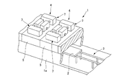
以下に、本発明にかかる壁面輻射式バーナーユニットの好適な一実施形態を、添付図面を参照して詳細に説明する。図1は、本実施形態に係る壁面輻射式バーナーユニットを備えた加熱炉1の構成を説明する一部破断斜視図である。本実施形態に係る加熱炉1は例えば、搬送される処理材2が予熱ゾーン、加熱ゾーン、均熱ゾーンを通過することにより加熱される連続式の加熱炉の一部を構成する。
Hereinafter, a preferred embodiment of a wall surface radiation type burner unit according to the present invention will be described in detail with reference to the accompanying drawings. FIG. 1 is a partially broken perspective view illustrating a configuration of a heating furnace 1 including a wall surface radiation type burner unit according to the present embodiment. The heating furnace 1 according to the present embodiment constitutes, for example, a part of a continuous heating furnace in which the
加熱炉1には図1に示すように、内部に、加熱される処理材2を搬送する、例えばウォーキングビームのような搬送部3が設けられている。壁面輻射式バーナーユニット4は、炉体エレメント5と、バーナーを構成する交番燃焼式の一対のリジェネレイティブバーナー装置7から構成される。交番燃焼式のリジェネレイティブバーナー装置7はよく知られているように、排気E(図2参照)で燃焼用空気Cを暖める蓄熱部11を有し、燃焼動作と排気動作を交互に行うようになっている。搬送部3で搬送される処理材2は、当該処理材2と対向し、バーナー装置7により焼かれて光輝状態に加熱される輻射壁面Zからの輻射熱により加熱される。本実施形態では、処理材2を加熱する輻射熱を発生する加熱炉1内面の輻射壁面Zが、処理材2の上方に位置する内面、すなわち加熱炉1の天井面6(図2参照)であって、この天井面6を壁面輻射式バーナーユニット4の炉体エレメント5で形成する場合を例にとって説明する。すなわち、図示例にあっては、炉体エレメント5は、炉体1aの炉天井部を形成し、左右一対の炉壁部及び炉床部と共に炉体1aを構成する。炉体エレメント5は、炉壁部や炉床部を形成するようにしてもよく、このような場合であっても、その他の炉天井部などと共に炉体1aを構成する。
As shown in FIG. 1, the heating furnace 1 is provided with a transport unit 3 such as a walking beam for transporting the
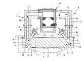
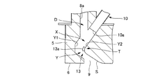
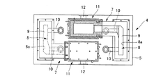
図2は、本実施形態に係る壁面輻射式バーナーユニット4の要部縦断面図であり、図3は、図2中A部拡大図であり、図4は、壁面輻射式バーナーユニット4の上面図である。図4では、後述する燃料噴射部10を省略して、空気流路8等を示している。壁面輻射式バーナーユニット4は図2に示すように、加熱炉1の内面としての天井面6を有し耐熱材でなる炉体エレメント5と、天井面6に沿う扁平火炎fを形成して当該天井面6を加熱する一対の蓄熱交番燃焼式のバーナー装置7とを備える。
2 is a longitudinal sectional view of a main part of the wall surface radiant burner unit 4 according to the present embodiment, FIG. 3 is an enlarged view of a portion A in FIG. 2, and FIG. 4 is an upper surface of the wall surface radiant burner unit 4. FIG. In FIG. 4, a
炉体エレメント5は、加熱炉1内に搬送される処理材2の搬送方向と直交する方向が長手方向となるほぼ長方形の天井面6を有する直方体状をなし、空気流路8を構成する第1流路8aが上方へ突出している。
The
炉体エレメント5の天井面6には、その長手方向の両端部側に、搬送方向に沿うスリット状に、開口部9がそれぞれ開口形成される。一対のリジェネレイティブバーナー装置7は、一方の燃焼動作時にその開口部9から扁平火炎fを吹き出し、他方の排気動作時にその開口部9から排気Eを吸引し、これら2つの開口部9で挟まれる領域が、扁平火炎fによって加熱されて固体輻射を生じる輻射壁面Zとなる。
炉体エレメント5には、開口部9を介して燃焼時に火炎fを噴き出し排気時に排気Eを吸引する空気流路8の一部と、空気流路8内に向かって燃料を噴射する燃料噴射部10と、点火用のパイロットバーナー(図示せず)とが備えられ、これらによってバーナー装置7が構成される。空気流路8は、上記第1流路8aと、炉体エレメント5の上側に設けられ蓄熱部11に接続された第2流路8bとから構成される。蓄熱部11には、吸排気用の連通管12が接続される。
In the
蓄熱交番燃焼式のバーナー装置7は上述したように、2台一組で構成される。一方のバーナー装置7の空気流路8を、燃料F及び燃焼用空気Cを供給する燃焼ガス供給路として使用する場合には、他方のバーナー装置7の空気流路8を、排気Eを排出する排気排出路として用い、切替操作で切り替えて交番燃焼される。各空気流路8と連通管12との間に設けられた蓄熱部11では、排気動作時に排気Eを排出する際の排熱を蓄熱し、燃焼動作時には、燃焼用空気Cが流通するときにこれを加熱するようになっている。これらバーナー装置7は、炉体エレメント5上に、対称な形状・構造で配置される。
As described above, the regenerative alternating
空気流路8と輻射壁面Zとは、開口部9を介して、連続する曲面Sによって・がるように形成される。空気流路8には、曲面Sの奥に位置させて、当該曲面Sに対し折り返す方向へ向けて湾曲経路Yが形成される。図示例では、空気流路8の第1流路8aは、下向きの直進経路Dと、開口部9側に・がって、炉体エレメント5の長手方向において、輻射壁面Zから反対側に張り出すように湾曲する湾曲経路Yとを有している。すなわち、第1流路8aは、上部では下向きに直進し、天井面6側となる下部では、天井面6と直交する方向より、輻射壁面Zに対し反対側へ張り出すように湾曲している。さらに詳しくは、湾曲経路Yは図3に示すように、直進経路D側では、輻射壁面Zから離れつつ天井面6側へ向かうように湾曲し、開口部9側では、輻射壁面Zに接近しつつ天井面6側へ向かうように湾曲している。これにより、燃焼動作時には、開口部9からは、燃焼用空気C及び燃料Fが、輻射壁面Zに沿って斜めに吹き出される。
The
蓄熱部11に接続される空気流路8の第2流路8bの水平部分は断面円形状である。他方、第1流路8aと接続される第2流路8bの鉛直部分は図4に示すように、開口部9の形状に合わせた第1流路8aの形状と合うように、下方へ向かって次第に幅広な矩形状に形成される。これによって、開口部9から吹き出す火炎fは、厚さの薄い扁平形状になる。開口部9の開口面積は、第1流路8aの断面積よりもわずかに小さく設定され、開口部9での流速が高められる。
A horizontal portion of the
各バーナー装置7の燃料噴射部10は、各開口部9の長手方向両端側に一対設けられ、湾曲経路Yに沿って空気流路8内へ燃料Fを噴射する。燃料噴射部10は、第1流路8aの輻射壁面Z側に設けられ、湾曲されて張り出した外側湾曲面Y1に向かって燃料Fが噴射される。燃料噴射部10の燃料噴射口10aは、直進経路D下部に位置されて、これにより、燃焼用空気Cと燃料Fは、湾曲経路Yの上流側を合流部Xとして合流される。
A pair of
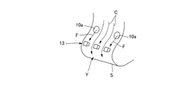
図5に示すように、空気流路8には、燃料噴射部10からの燃料Fと燃焼用空気Cとが合流する合流部Xよりも下流側であって、曲面Sが湾曲経路Yへ向かって折り返される反転部位T周辺に、燃料Fと燃焼用空気Cを撹拌混合するためのバッフル部13が形成される。図示例では、湾曲経路Yよりも直進経路D側において、外側湾曲面Y1と対向する内側湾曲面Y2から突出する突起としてのバッフル13aが開口部9の長手方向に適宜間隔を隔てて設けられる。燃焼用空気C及び燃料Fは、バッフル13aにより撹拌され混合が促進される。バッフル13aを避けてスムーズに流通する燃焼用空気Cは、撹拌混合された燃焼用空気C及び燃料Fを随伴して、開口部9から勢いよく吹き出すようになっている。この両方の作用により、扁平火炎fであっても、燃料/空気の混合と、流速の双方を維持できる。なお、燃料噴射部10は一対(2台)とは限らず、1台でも、3台以上であってもよい。
As shown in FIG. 5, the
開口部9から吹き出す火炎fは、輻射壁面Zに・がる曲面Sによって燃焼用空気Cの空気流に作用するコアンダ効果により、天井面6の輻射壁面Zに沿って進む扁平形状の火炎fとなる。さらに本実施形態では、一方のバーナー装置7の排気吸引動作に伴って生成される輻射壁面Zに沿う気流により、他方のバーナー装置7の燃焼動作による扁平火炎fが当該輻射壁面Zに確実に沿い、天井面6全体が光輝状態となる。これらにより、輻射壁面Z全面を効率よく熱して、固体輻射を生じさせて、処理材2を均一に加熱することができる。
The flame f blown out from the
本実施形態に係る壁面輻射式バーナーユニット4によれば、炉体エレメント5の輻射壁面Zを、蓄熱交番燃焼式の一対のバーナー装置7で生成される扁平火炎fにより加熱し、加熱された輻射壁面Z全面からの輻射熱により処理材2を加熱するので、バーナーの火炎を直接当てて加熱する場合よりも、均一に処理材2を加熱することができる。
According to the wall surface radiation type burner unit 4 according to the present embodiment, the radiation wall surface Z of the
扁平火炎fを、コアンダ効果を生じる燃焼用空気Cの空気流により輻射壁面Zに沿わせるようにしたので、効率よく輻射壁面Zを加熱することができる。また、一方のバーナー装置7の排気吸引動作に伴って生成される輻射壁面Zに沿う気流により、他方のバーナー装置7の燃焼動作による扁平火炎fを当該輻射壁面Zに沿わせることができ、これによっても輻射壁面Zを扁平火炎fで効率的に加熱することができる。
Since the flat flame f is caused to follow the radiation wall surface Z by the air flow of the combustion air C that causes the Coanda effect, the radiation wall surface Z can be efficiently heated. Further, the flat flame f generated by the combustion operation of the
詳細には、バーナー装置7に、炉体エレメント5に開口形成され、扁平火炎fを吹き出す開口部9と、炉体エレメント5に形成され、開口部9に接続されて燃焼用空気Cが流通される空気流路8とを備え、空気流路8と輻射壁面Zとを、開口部9を介して、連続する曲面Sで繋げて構成したので、開口部9から吹き出す火炎fをコアンダ効果により輻射壁面Zに沿わせることができる。そして、一対の蓄熱交番燃焼式のバーナー装置7により、扁平火炎fは、一方の開口部9から吹き出し、輻射壁面Zに沿って他方の開口部9へと吸引されるという一連の気流が生じており、扁平火炎fはその気流に伴って輻射壁面Zに沿って延びるので、確実かつ効率よく輻射壁面Zを加熱することができる。
Specifically, the
開口部9からの火炎fは、扁平状であるので、輻射壁面Zをより広くかつ均一に加熱できる。炉体エレメント5と処理材2との間に形成する火炎fが扁平状であるので、処理材2と天井面6等の炉体1a内面との間隔を狭く(図では、加熱炉1の高さを低く)することができ、加熱炉1を小型化することができる。
Since the flame f from the
バーナー装置7の空気流路8には、曲面Sの奥に位置させて、当該曲面Sに対し折り返す方向へ向けて湾曲経路Yが形成されているので、火炎fが開口部9から吹き出す際に、火炎fに、輻射壁面Zへ近づくように旋回作用を生じさせることができ、火炎fによる輻射壁面Zの加熱作用をさらに向上することができる。
Since the curved path Y is formed in the
バーナー装置7は、湾曲経路Yに沿って空気流路8内へ燃料Fを噴射する燃料噴射部10を有しているので、燃焼用空気Cのスムーズな流れを確保しつつこれら燃料Fと燃焼用空気Cとの合流を円滑化でき、流速の速い火炎fを開口部9から吹き出すことができる。
Since the
バーナー装置7の空気流路8には、燃料噴射部10からの燃料Fと燃焼用空気Cとが合流する合流部Xよりも下流側であって、曲面Sが湾曲経路Yへ向かって折り返される反転部位T周辺に、燃料Fと燃焼用空気Cを撹拌混合するためのバッフル部13が形成されているので、燃料Fと燃焼用空気Cの混合を高めることができ、高効率の燃焼を確保することができる。
In the
バッフル部13をスムーズに流れた燃焼用空気C及び燃料Fは、気流の勢いが維持されていて、コアンダ効果を十分に発揮させることができ、輻射壁面Zを適切に加熱して十分な輻射熱で処理材2を処理することができる。
Combustion air C and fuel F that flowed smoothly through the
また、上記実施形態のように、炉体エレメント5(図では、炉天井部)とバーナー装置7を含む壁面輻射式バーナーユニット4をユニット化することにより、これらを連設して炉天井部等の炉体1aを形成することで容易に加熱炉1を構成することができる。上記実施形態にあっては、炉体エレメント5を、炉天井部を構成するものとしたが、炉床部や炉壁部を構成するものであってもよいことはもちろんである。
Further, as in the above embodiment, the furnace body element 5 (furnace ceiling part in the figure) and the wall surface radiation type burner unit 4 including the
1 加熱炉
1a 炉体
2 処理材
3 搬送部
4 壁面輻射式バーナーユニット
5 炉体エレメント
6 天井面
7 リジェネレイティブバーナー装置
8 空気流路
8a 第1流路
8b 第2流路
9 開口部
10 燃料噴射部
10a 燃料噴射口
11 蓄熱部
12 連通管
13 バッフル部
13a バッフル
C 燃焼用空気
D 直進経路
E 排気
F 燃料
f 扁平火炎
S 曲面
T 反転部位
X 合流部
Y 湾曲経路
Y1 外側湾曲面
Y2 内側湾曲面
Z 輻射壁面
DESCRIPTION OF SYMBOLS 1
Claims (5)
前記バーナーは、前記炉体エレメントに形成され、扁平火炎を吹き出す開口部と、上記炉体エレメントに形成され、上記開口部に接続されて燃焼用空気が流通される空気流路とを備え、該空気流路と前記輻射壁面とは、上記開口部を介して、連続する曲面で繋がっていて、
前記バーナーの前記空気流路には、前記曲面の奥に位置させて、当該曲面に対し折り返す方向へ向けて湾曲経路が形成されていることを特徴とする壁面輻射式バーナーユニット。 A furnace element that forms a radiant wall facing the treatment material, and a burner that forms a flat flame along the radiant wall of the furnace element and heats the radiant wall, and is treated by radiant heat from the radiant wall. Heating the material ,
The burner includes an opening that is formed in the furnace body element and blows out a flat flame, and an air passage that is formed in the furnace body element and is connected to the opening and through which combustion air flows. The air flow path and the radiation wall surface are connected by a continuous curved surface through the opening,
A wall surface radiant burner unit characterized in that a curved path is formed in the air flow path of the burner so as to be located at the back of the curved surface and to be turned back with respect to the curved surface.
一方の上記リジェネレイティブバーナー装置の排気吸引動作に伴って生成される該輻射壁面に沿う気流により、他方の上記リジェネレイティブバーナー装置の燃焼動作による上記扁平火炎を当該輻射壁面に沿わせることを特徴とする請求項1〜4いずれかの項に記載の壁面輻射式バーナーユニット。 The burner has a heat storage section that warms combustion air with exhaust, and is configured by arranging a pair of regenerative burner devices that alternately perform combustion operation and exhaust operation with the radiation wall surface interposed therebetween,
The flat flame caused by the combustion operation of the other regenerative burner device is caused to flow along the radiation wall surface by the air flow along the radiation wall surface generated by the exhaust suction operation of the one regenerative burner device. The wall surface radiation type burner unit according to any one of claims 1 to 4, wherein
Priority Applications (5)
| Application Number | Priority Date | Filing Date | Title |
|---|---|---|---|
| JP2011213456A JP5774431B2 (en) | 2011-09-28 | 2011-09-28 | Wall surface radiant burner unit |
| KR1020147000986A KR101959098B1 (en) | 2011-09-28 | 2012-09-11 | Radiant wall burner unit |
| CN201280041924.5A CN103765101B (en) | 2011-09-28 | 2012-09-11 | Radiant wall burner unit |
| PCT/JP2012/073140 WO2013047183A1 (en) | 2011-09-28 | 2012-09-11 | Radiant wall burner unit |
| TW101134651A TWI548840B (en) | 2011-09-28 | 2012-09-21 | Wall surface heat radiation type burner unit |
Applications Claiming Priority (1)
| Application Number | Priority Date | Filing Date | Title |
|---|---|---|---|
| JP2011213456A JP5774431B2 (en) | 2011-09-28 | 2011-09-28 | Wall surface radiant burner unit |
Publications (3)
| Publication Number | Publication Date |
|---|---|
| JP2013072612A JP2013072612A (en) | 2013-04-22 |
| JP2013072612A5 JP2013072612A5 (en) | 2014-09-04 |
| JP5774431B2 true JP5774431B2 (en) | 2015-09-09 |
Family
ID=47995218
Family Applications (1)
| Application Number | Title | Priority Date | Filing Date |
|---|---|---|---|
| JP2011213456A Expired - Fee Related JP5774431B2 (en) | 2011-09-28 | 2011-09-28 | Wall surface radiant burner unit |
Country Status (5)
| Country | Link |
|---|---|
| JP (1) | JP5774431B2 (en) |
| KR (1) | KR101959098B1 (en) |
| CN (1) | CN103765101B (en) |
| TW (1) | TWI548840B (en) |
| WO (1) | WO2013047183A1 (en) |
Families Citing this family (6)
| Publication number | Priority date | Publication date | Assignee | Title |
|---|---|---|---|---|
| JP5878420B2 (en) * | 2012-04-19 | 2016-03-08 | 中外炉工業株式会社 | Wall radiant burner |
| JP2019527332A (en) | 2016-07-08 | 2019-09-26 | ノヴァ ケミカルズ(アンテルナショナル)ソシエテ アノニム | Metal burner components |
| FR3066508B1 (en) * | 2017-05-22 | 2021-02-12 | Matisa Materiel Ind Sa | PROCEDURE FOR LAYING A RAILWAY RAIL, INCLUDING HEATING OF THE RAIL, AND WORK TRAIN FOR IMPLEMENTING THE LAYING PROCEDURE |
| JP6727729B2 (en) * | 2017-07-07 | 2020-07-22 | 中外炉工業株式会社 | Heat treatment furnace |
| EP3598000B1 (en) * | 2018-07-20 | 2021-04-28 | Solaronics | Gas fired radiant emitter comprising a radiant screen |
| CN109487053A (en) * | 2019-01-10 | 2019-03-19 | 韩天臣 | Glowing furnace for daggers and swords |
Family Cites Families (20)
| Publication number | Priority date | Publication date | Assignee | Title |
|---|---|---|---|---|
| US4146357A (en) * | 1975-07-30 | 1979-03-27 | Hotwork International Limited | Fuel fired burners |
| JPS58185713A (en) * | 1982-04-24 | 1983-10-29 | Daido Steel Co Ltd | Heater |
| JPS5953620A (en) * | 1982-09-21 | 1984-03-28 | Sumitomo Metal Ind Ltd | Heating furnace |
| JPH0616260Y2 (en) * | 1988-02-03 | 1994-04-27 | 大阪瓦斯株式会社 | Radiant cup burner |
| AU7258391A (en) * | 1990-02-02 | 1991-08-21 | Glasstech Inc. | Gas fired radiant heater for furnace floor |
| GB2253576A (en) * | 1991-01-24 | 1992-09-16 | S & C Thermofluids Ltd | Catalytic Coanda combustion |
| CN2109497U (en) * | 1991-09-16 | 1992-07-08 | 中国科学院力学研究所 | Double wall mounted jet burner |
| JP2521386B2 (en) * | 1991-10-31 | 1996-08-07 | 日本ファーネス工業株式会社 | Steel heating furnace |
| CN1059027C (en) * | 1994-07-04 | 2000-11-29 | 中国科学院力学研究所 | Wall adsorption jet smooth burning method and premix burner thereof |
| FR2724217B1 (en) * | 1994-09-07 | 1996-10-25 | Air Liquide | DEVICE FOR SPREADING A FLAME BY COANDA EFFECT AND OVEN COMPRISING THIS DEVICE |
| JPH08159420A (en) * | 1994-12-03 | 1996-06-21 | Osaka Gas Co Ltd | Flat plane flame gas burner |
| JPH09101008A (en) * | 1995-10-03 | 1997-04-15 | Babcock Hitachi Kk | Radiation burner |
| JP2000046319A (en) * | 1998-07-28 | 2000-02-18 | Daido Steel Co Ltd | Method for controlling temperature of furnace provided with heat storage burner |
| FR2790309B1 (en) * | 1999-02-25 | 2001-05-11 | Stein Heurtey | IMPROVEMENTS IN OR RELATING TO FLAT BURNERS |
| TW546453B (en) * | 2000-09-07 | 2003-08-11 | John Zink Co Llc | High capacity/low NOx radiant wall burner |
| US6796789B1 (en) * | 2003-01-14 | 2004-09-28 | Petro-Chem Development Co. Inc. | Method to facilitate flameless combustion absent catalyst or high temperature oxident |
| US20070169513A1 (en) * | 2004-06-03 | 2007-07-26 | Yan Zhao | Glass Sheet Heating Surface |
| JP4969464B2 (en) * | 2008-01-08 | 2012-07-04 | 三菱重工業株式会社 | Burner structure |
| US8485813B2 (en) * | 2008-01-11 | 2013-07-16 | Hauck Manufacturing Company | Three stage low NOx burner system with controlled stage air separation |
| US20100021853A1 (en) * | 2008-07-25 | 2010-01-28 | John Zink Company, Llc | Burner Apparatus And Methods |
-
2011
- 2011-09-28 JP JP2011213456A patent/JP5774431B2/en not_active Expired - Fee Related
-
2012
- 2012-09-11 CN CN201280041924.5A patent/CN103765101B/en not_active Expired - Fee Related
- 2012-09-11 WO PCT/JP2012/073140 patent/WO2013047183A1/en active Application Filing
- 2012-09-11 KR KR1020147000986A patent/KR101959098B1/en active IP Right Grant
- 2012-09-21 TW TW101134651A patent/TWI548840B/en not_active IP Right Cessation
Also Published As
| Publication number | Publication date |
|---|---|
| CN103765101B (en) | 2016-03-09 |
| WO2013047183A1 (en) | 2013-04-04 |
| CN103765101A (en) | 2014-04-30 |
| TW201323787A (en) | 2013-06-16 |
| TWI548840B (en) | 2016-09-11 |
| JP2013072612A (en) | 2013-04-22 |
| KR101959098B1 (en) | 2019-03-15 |
| KR20140072011A (en) | 2014-06-12 |
Similar Documents
| Publication | Publication Date | Title |
|---|---|---|
| JP5774431B2 (en) | Wall surface radiant burner unit | |
| US9562682B2 (en) | Burner with a series of fuel gas ejectors and a perforated flame holder | |
| JP4808133B2 (en) | Gas burner | |
| JP2001000849A (en) | Premixer | |
| TWI614455B (en) | Heat gun for lifting the diversion effect | |
| JP5386230B2 (en) | Fuel burner and swirl combustion boiler | |
| CN212692482U (en) | Burner and industrial plant for firing ceramic articles | |
| EP3044509B1 (en) | Combustion method and industrial burner | |
| RU2606671C2 (en) | Device for transferring metallurgical material | |
| US20100024794A1 (en) | Direct-fired ductable heater | |
| RU2602573C2 (en) | Device for pre-heating of transported scrap | |
| JP5887430B2 (en) | High temperature FGR ultra-low NOx combustion system using Coanda effect | |
| JPH08208240A (en) | Glass-melting oven | |
| JP4860676B2 (en) | Continuous heating furnace | |
| JP5878420B2 (en) | Wall radiant burner | |
| JP2010060157A (en) | Exhausting equipment of heating furnace | |
| JP4459112B2 (en) | Burner apparatus and medium heating apparatus provided with the same | |
| JP5808120B2 (en) | Alternating combustion apparatus and alternating combustion method using the alternating combustion apparatus | |
| KR101506726B1 (en) | Furnace with gas nozzle | |
| JP4249510B2 (en) | Heating apparatus and heating method | |
| JP4145469B2 (en) | Side fired furnace equipped with a regenerative alternating combustion device | |
| JP2004286282A (en) | Hot air generating burner | |
| JP2007218557A (en) | Pulverized coal boiler | |
| JPH01118092A (en) | Furnace device | |
| CA2638435A1 (en) | Direct-fired ductable heater |
Legal Events
| Date | Code | Title | Description |
|---|---|---|---|
| A521 | Request for written amendment filed |
Free format text: JAPANESE INTERMEDIATE CODE: A523 Effective date: 20140723 |
|
| A621 | Written request for application examination |
Free format text: JAPANESE INTERMEDIATE CODE: A621 Effective date: 20140806 |
|
| TRDD | Decision of grant or rejection written | ||
| A01 | Written decision to grant a patent or to grant a registration (utility model) |
Free format text: JAPANESE INTERMEDIATE CODE: A01 Effective date: 20150623 |
|
| A61 | First payment of annual fees (during grant procedure) |
Free format text: JAPANESE INTERMEDIATE CODE: A61 Effective date: 20150701 |
|
| R150 | Certificate of patent or registration of utility model |
Ref document number: 5774431 Country of ref document: JP Free format text: JAPANESE INTERMEDIATE CODE: R150 |
|
| R250 | Receipt of annual fees |
Free format text: JAPANESE INTERMEDIATE CODE: R250 |
|
| R250 | Receipt of annual fees |
Free format text: JAPANESE INTERMEDIATE CODE: R250 |
|
| LAPS | Cancellation because of no payment of annual fees |