JP4459112B2 - Burner apparatus and medium heating apparatus provided with the same - Google Patents
Burner apparatus and medium heating apparatus provided with the same Download PDFInfo
- Publication number
- JP4459112B2 JP4459112B2 JP2005156675A JP2005156675A JP4459112B2 JP 4459112 B2 JP4459112 B2 JP 4459112B2 JP 2005156675 A JP2005156675 A JP 2005156675A JP 2005156675 A JP2005156675 A JP 2005156675A JP 4459112 B2 JP4459112 B2 JP 4459112B2
- Authority
- JP
- Japan
- Prior art keywords
- combustion
- gas
- mixing
- fuel
- combustion air
- Prior art date
- Legal status (The legal status is an assumption and is not a legal conclusion. Google has not performed a legal analysis and makes no representation as to the accuracy of the status listed.)
- Expired - Fee Related
Links
Images


Landscapes
- Gas Burners (AREA)
Description
本発明は、給湯器などに適用されるバーナ装置及びこれを備えた媒体加熱装置に関する。 The present invention relates to a burner device applied to a water heater or the like and a medium heating device provided with the burner device.
従来、給湯器、ボイラ、加熱炉、ストーブなどの燃焼装置においては、燃料用ガスを燃料として用いるバーナ装置が広く用いられている。このバーナ装置の一例として、全一次空気式バーナ装置が知られている。この全一次バーナ装置は、混合室を有するバーナ本体と、複数の炎孔を有する燃焼プレートと、混合室に燃料用ガスを供給するための燃料用ガス供給手段と、混合室に燃焼用空気を供給するための燃焼用空気供給手段と、を備え、燃焼プレートはフェルト状金属繊維板、多孔質セラミック板、多数の炎孔(例えば円形状孔)を設けた金属プレートなどから構成される。 Conventionally, in a combustion apparatus such as a water heater, a boiler, a heating furnace, and a stove, a burner apparatus using a fuel gas as a fuel is widely used. As an example of this burner device, an all-primary pneumatic burner device is known. This all-primary burner device comprises a burner body having a mixing chamber, a combustion plate having a plurality of flame holes, fuel gas supply means for supplying fuel gas to the mixing chamber, and combustion air to the mixing chamber. Combustion air supply means for supplying, and the combustion plate is formed of a felt-like metal fiber plate, a porous ceramic plate, a metal plate provided with a number of flame holes (for example, circular holes), and the like.
このような全一次空気式バーナ装置においては、燃料用ガス供給手段からの燃料用ガスと燃焼用空気供給手段からの燃焼用空気とが混合室内で実質上均一に混合され、均一に混合された混合ガス(燃料用ガスと燃焼用空気とが混合したガス)が燃焼プレートの多数の炎孔から噴出して燃焼する。 In such an all primary air burner apparatus, the fuel gas from the fuel gas supply means and the combustion air from the combustion air supply means are substantially uniformly mixed and uniformly mixed in the mixing chamber. A mixed gas (a gas in which fuel gas and combustion air are mixed) is ejected from many flame holes of the combustion plate and burned.
この種の全一次空気式バーナ装置では、予混合燃焼である高空気比燃焼(平均の空気比が1以上である燃焼)が実現できるために、燃焼の低NOx化を図ることができるとともに、バーナ装置自体の構造が簡単になるために、バーナ装置のコンパクト化を図ることができる。 In this kind of all primary air burner device, high air ratio combustion that is premixed combustion (combustion with an average air ratio of 1 or more) can be realized, so that it is possible to achieve low NOx combustion, Since the structure of the burner device itself is simplified, the burner device can be made compact.
しかし、燃料用ガスと燃焼用空気とを予め均一に混合した高空気比混合ガスを小さい炎孔から噴出させて燃焼させるために、燃焼プレート表面の燃焼面上に形成される各火炎(各炎孔から噴出する混合ガスの燃焼による火炎)の空気比が実質上等しく、それ故に、各火炎のバランスが揃って互いに干渉して燃焼振動が発生し易く、この燃焼振動による共鳴音が発生し易くなる。 However, each flame (each flame) formed on the combustion surface of the combustion plate surface in order to inject and burn a high air ratio mixed gas in which fuel gas and combustion air are uniformly mixed in advance from a small flame hole. The air ratio of the flames (combustion of the mixed gas ejected from the holes) is substantially equal. Therefore, the flames are balanced and interfere with each other, and combustion vibrations are likely to occur. Resonance noise due to these combustion vibrations is likely to occur. Become.
このような燃焼振動の発生を抑えるために、バーナ本体の混合室における燃料用ガスと燃焼用空気との混合状態が不均一になるように構成したバーナ装置が提案されている(例えば、特許文献1参照)。このバーナ装置では、燃焼プレートの複数の炎孔から噴出する混合ガスの空気比にムラが存在し、それ故に、燃焼プレートの燃焼面上に形成される火炎が不均一になり、各火炎の固有の振動周波数が異なるようになる。従って、燃焼火炎が相互に干渉することがなく、これによって、燃焼振動の発生が抑えられ、燃焼振動による共鳴音の発生を防止することができる。 In order to suppress the occurrence of such combustion vibration, there has been proposed a burner device configured such that the mixing state of the fuel gas and the combustion air in the mixing chamber of the burner body is non-uniform (for example, Patent Documents). 1). In this burner device, there is unevenness in the air ratio of the mixed gas ejected from the plurality of flame holes of the combustion plate. Therefore, the flame formed on the combustion surface of the combustion plate becomes non-uniform, and each flame has its own characteristic. The vibration frequency becomes different. Accordingly, the combustion flames do not interfere with each other, thereby suppressing the generation of combustion vibrations and preventing the generation of resonance noise due to the combustion vibrations.
しかしながら、空気比ムラを存在させた全一次空気式バーナ装置においては、高負荷燃焼時に燃焼用空気の流速分布が不均一であると、燃焼用空気の流速が速い領域では空気流量自体も多くなり、それ故に、この領域における混合ガスの濃度が相対的に薄くなる(空気比が高くなる)。また、燃焼用空気の流速が速い領域では燃焼プレートの炎孔から噴出する混合ガスの噴出流速も速くなり、これらのことに起因して、燃焼プレートでの火炎の保炎が難しくなる。また、低負荷燃焼時では燃料用ガスの供給を絞るとともに、これに合わせて燃焼用空気の供給量を絞るために、燃焼プレートの炎孔から噴出する混合ガスの流速が遅くなる。このように流速が遅くなると、各炎孔の火炎が燃焼プレートに近づき、燃焼プレートの温度が高くなり、その表面が赤熱する傾向になる。 However, in an all-primary air burner system that has air ratio unevenness, if the flow velocity distribution of combustion air is not uniform during high-load combustion, the air flow rate itself increases in the region where the combustion air flow velocity is high. Therefore, the concentration of the mixed gas in this region is relatively thin (the air ratio is high). In addition, in the region where the flow velocity of the combustion air is high, the flow velocity of the mixed gas ejected from the flame hole of the combustion plate is also increased, which makes it difficult to hold the flame on the combustion plate. Further, at the time of low-load combustion, the supply of the fuel gas is restricted, and the supply amount of the combustion air is restricted accordingly, so that the flow rate of the mixed gas ejected from the flame hole of the combustion plate becomes slow. Thus, when the flow velocity becomes slow, the flame of each flame hole approaches the combustion plate, the temperature of the combustion plate increases, and the surface tends to become red hot.
この高負荷燃焼時の保炎に関する問題を解消するためには、混合室内に整流板を配設する、混合室内に整流部を設けるなどすればよいが、整流板を設けるように構成した場合、整流板が抵抗となるために、燃焼用空気供給手段を構成する空気供給ファンの駆動動力が増大し、バーナ装置としての総合的な効率が低下するという問題が生じる。また、整流部を設けるように構成した場合、全一次空気式バーナ装置の長所であるコンパクト性が損なわれる。また、低負荷燃焼時の燃焼プレートの赤熱に関する問題を解消するためには、燃焼用空気の供給量を幾分増大して各炎孔の火炎を燃焼プレートから離すようにすればよいが、このようにした場合、混合ガスの空気比が高くなり(燃料用ガスが薄くなる)、混合ガスの燃焼が不安定になるという問題が生じる。 In order to solve the problem related to flame holding during high-load combustion, a rectifying plate may be provided in the mixing chamber, a rectifying unit may be provided in the mixing chamber, but when the rectifying plate is provided, Since the rectifying plate becomes a resistance, the driving power of the air supply fan constituting the combustion air supply means increases, resulting in a problem that the overall efficiency of the burner device is lowered. Moreover, when comprised so that a rectification | straightening part may be provided, the compactness which is the advantage of all the primary air type burner apparatuses is impaired. Moreover, in order to solve the problem related to the red heat of the combustion plate at the time of low load combustion, it is only necessary to increase the supply amount of the combustion air somewhat so that the flame of each flame hole is separated from the combustion plate. In such a case, there is a problem that the air ratio of the mixed gas becomes high (the fuel gas becomes thin) and the combustion of the mixed gas becomes unstable.
本発明の目的は、高負荷燃焼時においては燃焼用空気の流速分布が不均一であっても燃焼プレートでの保炎を良好に保つことができるとともに、低負荷燃焼時においては燃焼プレート表面の赤熱を回避しながら安定して燃焼させることができるバーナ装置を提供することである。 The object of the present invention is to maintain good flame holding on the combustion plate even when the flow velocity distribution of the combustion air is non-uniform during high-load combustion, and the surface of the combustion plate during low-load combustion. It is an object of the present invention to provide a burner device that can stably burn while avoiding red heat.
また、本発明の他の目的は、低負荷燃焼から高負荷燃焼にわたって安定して燃焼して媒体を加熱することができる媒体加熱装置を提供することである。 Another object of the present invention is to provide a medium heating apparatus that can stably burn and heat a medium from low load combustion to high load combustion.
本発明の請求項1に記載のバーナ装置は、燃料用ガスと燃焼用空気とを混合するための混合部と、複数の炎孔を有する燃焼プレートと、前記混合部に燃料用ガスを供給するための燃料用ガス供給手段と、前記混合部に燃焼用空気を供給するための燃焼用空気供給手段と、を備え、前記燃料用ガス供給手段から供給される燃料用ガスと前記燃焼用空気供給手段から供給される燃焼用空気とが前記混合部にて混合され、この混合された混合ガスが前記燃焼プレートの前記複数の炎孔から噴出して燃焼するバーナ装置であって、
前記混合部は所定方向に並設された複数の混合ユニットから構成され、前記複数の混合ユニットの各々は、それぞれ、前記燃焼プレートに向けて流れる燃焼用空気に燃料用ガスを混合するための第1及び第2混合流路と、燃料用ガスを噴出するためのガス噴出口を有する燃料噴出ノズルとを備えており、
各混合ユニットの前記第1及び第2混合流路は仕切壁を介して相互に隣接して設けられ、前記燃料噴出ノズルは前記第1混合流路に配設され、前記仕切壁には前記燃料噴出ノズルの前記ガス噴出口に対応してガス供給孔が設けられており、
高負荷燃焼時には、前記燃料噴出ノズルの前記ガス噴出口から噴出される燃料用ガスの噴出量が多く、前記ガス噴出口からの燃料用ガスの噴出量の多くが前記仕切壁の前記ガス供給孔を通して前記第2混合流路に供給され、また低負荷燃焼時には、前記燃料噴出ノズルの前記ガス噴出口から噴出される燃料用ガスの噴出量が少なく、前記ガス噴出口からの燃料用ガスの噴出量の多くが前記第1混合流路に供給されることを特徴とする。
The burner device according to
The mixing unit includes a plurality of mixing units arranged in parallel in a predetermined direction, and each of the plurality of mixing units is configured to mix a fuel gas with combustion air flowing toward the combustion plate. 1 and a second mixing flow path, and a fuel ejection nozzle having a gas ejection port for ejecting fuel gas,
The first and second mixing channels of each mixing unit are provided adjacent to each other via a partition wall, the fuel ejection nozzle is disposed in the first mixing channel, and the fuel A gas supply hole is provided corresponding to the gas outlet of the jet nozzle,
During high-load combustion, the amount of fuel gas ejected from the gas ejection port of the fuel ejection nozzle is large, and the amount of fuel gas ejection from the gas ejection port is large in the gas supply hole of the partition wall In the low-load combustion, the amount of fuel gas ejected from the gas ejection port of the fuel ejection nozzle is small, and the fuel gas ejection from the gas ejection port A large amount is supplied to the first mixing channel.
また、本発明の請求項2に記載のバーナ装置は、請求項1に記載のバーナ装置と、前記バーナ装置の前記燃焼プレートの前記複数の炎孔における混合ガスの燃焼によって生成される燃焼ガスが流れる燃焼ガス流路と、熱を受ける受熱媒体が流れる受熱管と、を備え、前記受熱管が前記燃焼ガス流路内に配設され、前記燃焼ガス流路を流れる燃焼ガスと前記受熱管を流れる受熱媒体との間で熱交換が行われることを特徴とする。 A burner device according to a second aspect of the present invention includes a burner device according to the first aspect, and a combustion gas generated by combustion of a mixed gas in the plurality of flame holes of the combustion plate of the burner device. A combustion gas flow path that flows, and a heat receiving pipe through which a heat receiving medium that receives heat flows. The heat receiving pipe is disposed in the combustion gas flow path, and the combustion gas flowing through the combustion gas flow path and the heat receiving pipe Heat exchange is performed with the flowing heat receiving medium.
本発明の請求項1に記載のバーナ装置によれば、バーナ本体の混合部は複数の混合ユニットから構成され、各混合ユニットは、燃焼用空気に燃料用ガスを混合するための第1及び第2混合流路と、燃料用ガスを噴出するためのガス噴出口を有する燃料噴出ノズルとを備え、燃料噴出ノズルが第1混合流路に配設され、燃料噴出ノズルのガス噴出口からの燃料用ガスは、第1及び第2混合流路を流れる燃焼用空気とガス噴出口から噴出される燃料用ガスとの運動エネルギーを利用して第1及び第2混合流路に分配供給されるように構成されている。 According to the burner device of the first aspect of the present invention, the mixing section of the burner body is composed of a plurality of mixing units, and each mixing unit has a first and a second for mixing the fuel gas with the combustion air. A fuel jet nozzle having a gas jet nozzle for jetting fuel gas, the fuel jet nozzle being disposed in the first mix channel, and fuel from the gas jet port of the fuel jet nozzle The gas for use is distributed and supplied to the first and second mixing channels using the kinetic energy of the combustion air flowing through the first and second mixing channels and the fuel gas ejected from the gas outlet. It is configured.
高負荷燃焼時においては、燃料噴出ノズルのガス噴出口から噴出される燃料用ガスの噴出量が多く、その運動エネルギーは大きいために、燃料用ガスの噴出量の多くが仕切壁のガス供給孔を通して第2混合流路に供給される。従って、混合ユニットの第2混合流路を通して炎孔から噴出される混合ガスの空気比と混合ユニットの第1混合流路を通して炎孔から噴出される混合ガスの空気比とに差異が生じるようになる。その結果、燃焼プレートの燃焼火炎の相互干渉が抑えられ、相互干渉による燃焼振動の発生を防止することができる。 During high-load combustion, the amount of fuel gas ejected from the gas ejection port of the fuel ejection nozzle is large and its kinetic energy is large, so that most of the fuel gas ejection amount is the gas supply hole in the partition wall. Through the second mixing channel. Accordingly, the air ratio of the mixed gas ejected from the flame hole through the second mixing flow path of the mixing unit is different from the air ratio of the mixed gas ejected from the flame hole through the first mixing flow path of the mixing unit. Become. As a result, the mutual interference of the combustion flame of the combustion plate is suppressed, and the generation of combustion vibration due to the mutual interference can be prevented.
また、この高負荷燃焼時において燃焼用空気の流速分布が不均一になって一部の混合ユニットにおいて燃焼用空気の流量が幾分多くなったときには、この混合ユニット(第1混合流路及び第2混合流路)を流れる燃焼用空気の流速が幾分速くなり、燃焼プレートの炎孔から噴出する混合ガスの流速も幾分速くなり、炎孔における燃焼火炎の保炎がし難い状態となる。この状態においては、第1混合流路を流れる燃焼用空気の流速が幾分速く、この燃焼用空気の運動エネルギーも、燃焼用空気の流量が幾分少ない状態と比較して、幾分大きくなっている。このような状態にあるので、燃焼用空気の流量が幾分多い状態は、燃焼用空気の流量が幾分少ない状態に比して、燃料噴出ノズルのガス噴出口から噴出される燃料用ガスは、第1混合流路へ幾分多く分配されるようになる。その結果、燃焼用空気の流量が幾分少ない状態に比して、第1混合流路における混合ガスの空気比が幾分低くなり(燃料用ガスの濃度が幾分高くなる)、第1混合流路の炎孔から噴出する混合ガスの流速が幾分速いにもかかわらず、この第1混合流路の炎孔から噴出する混合ガスの燃焼火炎は安定し、この安定した燃焼火炎でもって、第2混合流路の炎孔から噴出する混合ガスの燃焼火炎を安定させることができる。また、この高負荷燃焼時において燃焼用空気の流速分布が不均一になって一部の混合ユニットにおいて燃焼用空気の流量が幾分少なくなったときには、この混合ユニット(第1混合流路及び第2混合流路)を流れる燃焼用空気の流速が幾分遅くなり、燃焼プレートの炎孔から噴出する混合ガスの流速も幾分遅くなり、炎孔における燃焼火炎の保炎がし易い状態となる。この状態においては、第1混合流路を流れる燃焼用空気の流速も幾分遅く、この燃焼用空気の運動エネルギーも、燃焼用空気の流量が幾分多い状態と比較して、幾分小さくなっている。このような状態にあるので、燃焼用空気の流量が幾分少ない状態は、燃焼用空気の流量が幾分多い状態に比して、燃料噴出ノズルのガス噴出口から噴出される燃料用ガスは、第1混合流路へ幾分少なく分配されるようになる。その結果、燃焼用空気の流量が幾分多い状態に比して、第1混合流路における混合ガスの空気比が幾分高くなる(燃料用ガスの濃度が幾分低くなる)が、第1混合流路の炎孔から噴出する混合ガスの流速が幾分遅いために、このような状態においても第1混合流路の炎孔から噴出する混合ガスの燃焼火炎は安定し、この安定した燃焼火炎でもって、第2混合流路の炎孔から噴出する混合ガスの燃焼火炎を安定させることができる。このように高負荷燃焼時に燃焼用空気の流速分布が不均一になったとしても、燃焼プレートの炎孔から噴出する混合ガスの燃焼火炎を安定させることができる。 Further, when the flow velocity distribution of the combustion air becomes non-uniform during the high load combustion and the flow rate of the combustion air is somewhat increased in some mixing units, the mixing unit (the first mixing flow path and the first mixing flow path) 2) The flow velocity of the combustion air flowing through the two mixing channels) is somewhat faster, the flow velocity of the mixed gas ejected from the flame holes of the combustion plate is also somewhat faster, and it becomes difficult to hold the combustion flame in the flame holes. . In this state, the flow velocity of the combustion air flowing through the first mixing channel is somewhat faster, and the kinetic energy of this combustion air is also somewhat higher than in the state where the flow rate of the combustion air is somewhat lower. ing. In such a state, when the flow rate of the combustion air is somewhat high, the fuel gas injected from the gas outlet of the fuel injection nozzle is smaller than when the flow rate of the combustion air is somewhat low. , Somewhat more distribution into the first mixing channel. As a result, the air ratio of the mixed gas in the first mixing flow path is somewhat lower (the concentration of the fuel gas is somewhat higher) than in the state where the flow rate of the combustion air is somewhat lower, and the first mixing Although the flow velocity of the mixed gas ejected from the flame hole of the flow path is somewhat high, the combustion flame of the mixed gas ejected from the flame hole of the first mixed flow path is stable, and with this stable combustion flame, The combustion flame of the mixed gas ejected from the flame hole of the second mixing channel can be stabilized. Further, when the flow velocity distribution of the combustion air becomes non-uniform during the high-load combustion and the flow rate of the combustion air is somewhat reduced in some of the mixing units, the mixing unit (the first mixing flow path and the first mixing flow path). 2) The flow velocity of the combustion air flowing through the two mixing channels) is somewhat slow, the flow velocity of the mixed gas ejected from the flame holes of the combustion plate is also somewhat slow, and it becomes easy to hold the combustion flame in the flame holes. . In this state, the flow velocity of the combustion air flowing through the first mixing channel is also somewhat slower, and the kinetic energy of this combustion air is also somewhat smaller than in the state where the flow rate of the combustion air is somewhat higher. ing. In this state, when the flow rate of the combustion air is somewhat low, the fuel gas injected from the gas outlet of the fuel injection nozzle is less than when the flow rate of the combustion air is somewhat high. , Somewhat less distributed to the first mixing channel. As a result, the air ratio of the mixed gas in the first mixing channel is somewhat higher (the concentration of the fuel gas is somewhat lower) than in the state where the flow rate of the combustion air is somewhat higher. Since the flow velocity of the mixed gas ejected from the flame hole of the mixing channel is somewhat slow, even in such a state, the combustion flame of the mixed gas ejected from the flame hole of the first mixing channel is stable, and this stable combustion With the flame, the combustion flame of the mixed gas ejected from the flame hole of the second mixing channel can be stabilized. Thus, even if the flow velocity distribution of the combustion air becomes non-uniform during high load combustion, the combustion flame of the mixed gas ejected from the flame holes of the combustion plate can be stabilized.
更に、低負荷燃焼時には、燃焼用空気の流量を絞り過ぎずに幾分多めに設定した状態にて燃料用ガスの供給量を絞るようになる。このような供給状態では、燃料噴出ノズルのガス噴出口から噴出される燃料用ガスの噴出量が少なくてその運動エネルギーが小さく、また第1混合流路を流れる燃焼用空気の運動エネルギーも小さいが、燃焼用空気の流量は絞り過ぎずに幾分多めに設定されているので、ガス噴出口からの燃料用ガスの噴出量の比較的多く(この場合、噴出量の大部分)が第1混合流路に供給される。その結果、第1混合流路の混合ガスの空気比が高く(燃料用ガスの濃度が薄く)なり過ぎず、この混合ガスの燃焼を安定させることができる。また、このときには、燃焼用空気の流量が少なくて燃焼プレート表面が赤熱する傾向にあるが、燃焼用空気の流量が幾分多めに設定されているために、燃焼火炎が燃焼プレートから離れ、安定した燃焼状態を保ちながらこの赤熱の発生を回避することができる。 Further, at the time of low load combustion, the supply amount of the fuel gas is reduced in a state where the flow rate of the combustion air is set somewhat higher without being excessively reduced. In such a supply state, the amount of fuel gas ejected from the gas ejection port of the fuel ejection nozzle is small and its kinetic energy is small, and the kinetic energy of the combustion air flowing through the first mixing channel is also small. The flow rate of the combustion air is set to be slightly higher without being restricted too much, so that a relatively large amount of fuel gas is ejected from the gas outlet (in this case, the majority of the ejection amount) is the first mixture. Supplied to the flow path. As a result, the air ratio of the mixed gas in the first mixing channel does not become too high (the concentration of the fuel gas is too thin), and the combustion of this mixed gas can be stabilized. In this case, the combustion air flow rate is low and the surface of the combustion plate tends to become red hot. However, since the combustion air flow rate is set somewhat higher, the combustion flame is separated from the combustion plate and stabilized. The generation of red heat can be avoided while maintaining the burned state.
また、本発明の請求項2に記載の媒体加熱装置によれば、上述したバーナ装置を備えているので、高負荷燃焼時には燃焼用空気の流速分布が不均一になったとしても、良好な保炎状態を保って燃焼プレートでの燃焼火炎を安定させることができ、また低負荷燃焼時には燃焼プレートの赤熱を回避しながら燃焼火炎を安定させることができ、燃焼火炎が安定した媒体加熱装置を提供することができる。尚、この媒体加熱装置は例えば給湯器であり、この場合、受熱媒体は例えば水(水道水)である。 Further, according to the medium heating device of the second aspect of the present invention, since the above-described burner device is provided, even when the flow velocity distribution of the combustion air becomes non-uniform during high load combustion, good maintenance is achieved. Provides a medium heating device that can stabilize the combustion flame on the combustion plate while maintaining the flame state, and can stabilize the combustion flame while avoiding the red heat of the combustion plate during low load combustion. can do. The medium heating device is, for example, a water heater, and in this case, the heat receiving medium is, for example, water (tap water).
以下、添付図面を参照して、本発明に従うバーナ装置及びこれを備えた媒体加熱装置について説明する。図1は、本発明に従うバーナ装置を一部切り欠いて示す断面図であり、図2は、図1のバーナ装置を示す平面から見た断面図であり、図3は、図1のバーナ装置における一つの混合ユニット及びその近傍を示す断面図であり、図4は、低負荷燃焼時の混合ユニットの燃料用ガスの流れを説明するための断面図であり、図5は、高負荷燃焼時の燃焼用空気の流量が幾分多いときの混合ユニットにおける燃料用ガスの流れを説明するための断面図であり、図6は、高負荷燃焼時の燃焼用空気の流量が幾分少ないときの混合ユニットにおける燃料用ガスの流れを説明するための断面図であり、図7は、図1のバーナ装置を備えた媒体加熱装置を一部切り欠いて示す正面断面図である。 Hereinafter, a burner device according to the present invention and a medium heating device including the same will be described with reference to the accompanying drawings. FIG. 1 is a cross-sectional view of the burner device according to the present invention, partly cut away, FIG. 2 is a cross-sectional view of the burner device of FIG. 1 as seen from the plane, and FIG. 3 is the burner device of FIG. FIG. 4 is a cross-sectional view for explaining the flow of fuel gas in the mixing unit during low-load combustion, and FIG. 5 is a view during high-load combustion. FIG. 6 is a cross-sectional view for explaining the flow of fuel gas in the mixing unit when the flow rate of combustion air is somewhat high, and FIG. 6 is a view when the flow rate of combustion air during high load combustion is somewhat low FIG. 7 is a cross-sectional view for explaining the flow of fuel gas in the mixing unit, and FIG. 7 is a front cross-sectional view showing a part of the medium heating device including the burner device of FIG.
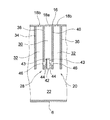
図1及び図2において、図示のバーナ装置2は方形枠状のバーナ本体4を備え、バーナ本体4は矩形状の底壁6及びこの底壁6から上方に延びる4側壁8,10,12,14を有し、このバーナ本体4の上端部(4側壁8,10,12,14の上端部)に燃焼プレート16が設けられている。燃焼プレート16は例えば金属プレートから構成され、その実質上全域に複数の小さい炎孔18が設けられている。これら炎孔18は、例えば円形状、楕円形状などの適宜の形状でよく、例えば打抜き加工などで形成することができる。
1 and 2, the illustrated
この実施形態では、バーナ本体4内の上部に燃料用ガスと燃焼用空気とを混合するための混合部20が設けられ、バーナ本体4の下部(混合部20の下側)には、混合部20に向けて燃焼用空気が流れる空気流路部22が設けられている。またバーナ本体4の底壁6には、燃焼用空気供給手段24を構成する送風ファン26が取り付けられ、かかる送風ファン26からの空気(燃焼用空気として利用される)がバーナ本体4の底壁6に設けられた供給開口(図示せず)を通して流入し、かく流入した燃焼用空気は空気流路部22を通して混合部20に送給される。
In this embodiment, a mixing
この実施形態では、混合部20は複数(図示の例では、6個)の混合ユニット28から構成されている。混合ユニット28はバーナ本体4内に所定方向(図1及び図2において左右方向)に並設して設けられ、これら混合ユニット28にて燃料用ガスと燃焼用空気とが後述する如く混合され、かく混合された混合ガスが燃焼プレート16の複数の炎孔18から噴出される。複数の混合ユニット28は実質上同一の構成であり、図3をも参照して、これら混合ユニット28の一つについて説明する。
In this embodiment, the mixing
図示の混合ユニット28は、少なくとも一つの第1混合流路30と、この第1混合流路30に隣接して並設された少なくとも一つの第2混合流路32とを有し、図示の形態では、第1混合流路30の両側に第2混合流路32が配設されている。各混合ユニット28は一対のユニット壁34,36と、一対のユニット壁34,36の内側に配設された一対の仕切壁38,40を備え、一対の仕切壁38,40の間に第1混合流路30が規定され、片側(図1〜図3において左側)のユニット壁34(図1及び図2において左端に位置する混合ユニット28においては、バーナ本体4の側壁14をこのユニット壁として用いるようにしてもよい)と片側の仕切壁38との間に一方の第2混合流路32が規定され、他側(図1〜図3において右側)のユニット壁36(図1及び図2において右端に位置する混合ユニット28においては、バーナ本体4の側壁10をこのユニット壁として用いるようにしてもよい)と他側の仕切壁40との間に他方の第2混合流路32が規定されている。これら第1及び第2混合流路30,32の上流端(下端)は空気流路部22に連通しており、それらの下流端(上端)には燃焼プレート16が設けられ、混合ユニット28の第1及び第2混合流路30,32に対応して複数の炎孔18が設けられている。この形態では、燃焼プレート16の第1混合流路30を覆う部位には炎孔18a(図3参照)が設けられ、炎孔18aは第1混合流路30の奥行き方向(図1において左下から右上の方向、図2において上下方向、図3において紙面に垂直な方向)に間隔をおいて複数設けられている。また、燃焼プレート16の第2混合流路32を覆う部位には炎孔18b(図3参照)が設けられ、炎孔18bは第2混合流路32の奥行き方向に間隔をおいて複数設けられている。
The illustrated
各混合ユニット28の第1混合流路30には、燃料用ガスが噴出する燃料噴出ノズル42が配設されている。燃料噴出ノズル42は例えば断面形状が矩形状の筒状部材から構成され、一対の仕切壁38,40間を仕切壁38,40に沿って実質上平行に奥行き方向に延び、その先端は閉塞されている。燃料噴出ノズル42は第1混合流路30の上流部に配置され、一対の仕切壁38,40に対向する側壁部43にガス噴出口44が設けられ、かかるガス噴出口44は燃料噴出ノズル42の長手方向(即ち、第1混合流路30の奥行き方向)に間隔をおいて複数設けられている。燃料噴出ノズル42は、断面形状が円形状、楕円形状などの適宜の形状でよく、またガス噴出口44も、円形状、楕円形状などの適宜の形状でよい。
A
燃料噴射ノズル42の各ガス噴出口44に対応して、一対の仕切壁38,40の所定部位にはガス供給孔46が設けられている。即ち、燃料噴出ノズル42の片側(図3において左側)に設けられた各ガス噴出口44に対応して、片側の仕切壁38の各ガス噴出口44に対向する部位にガス供給孔46が設けられ、また燃料噴出ノズル42の他側(図3において右側)に設けられた各ガス噴出口44に対応して、他側の仕切壁40の各ガス噴出口44に対向する部位にガス供給孔46が設けられている。各ガス供給孔46の大きさは燃料噴出ノズル42のガス噴出口44の大きさよりも大きく、これらガス噴出口44から後述する如く噴出された燃料用ガスは、ガス供給孔46を通して第2混合流路32に流れ易くなっている。
Corresponding to each
バーナ本体4の側壁8の外側には、燃料用ガス供給手段50を構成するガス供給管52が設けられ、ガス供給管52はバーナ本体4の横方向(図1及び図2において左右方向である幅方向)に延びている。各混合ユニット28に配設された燃料噴出ノズル42の一端側はバーナ本体4の側壁8を貫通してガス供給管52内に連通され、ガス供給管52はガスボンベ、ガス埋設管などのガス供給源に接続され、ガス供給源からの燃料用ガス(例えば、都市ガス、LPガスなど)が、矢印54で示すように、ガス供給管52を通して各混合ユニット28の燃料噴出ノズル42に供給される。
A
次に、主として図1とともに図4〜図6を参照して、上述したバーナ装置2の燃焼について説明する。バーナ装置2を燃焼させるときには、ガス供給源(図示せず)からの燃料用ガスがガス供給管52に供給されるとともに、送風ファン26からの燃焼用空気がバーナ本体4の空気流路部22に供給される。ガス供給管52に供給された燃料は、各混合ユニット28の燃料噴出ノズル42に送給され、各燃料噴出ノズル42内を先端に向けて流れ、各燃料噴出ノズル44から噴出する。また、バーナ本体4の空気流路部22に供給された燃焼用空気は、各混合ユニット28の第1及び第2混合流路30,32に流れ、第1及び第2混合流路30,32を流れる燃焼用空気に、燃料噴出ノズル42からの燃料用ガスが噴出されて混合され、混合ユニット28の第1混合流路30にて混合された混合ガス(燃料用ガスと燃焼用空気とが混合されたガス)は燃焼プレート16の炎孔18aから噴出して燃焼され、燃料噴出ノズル42から仕切壁38,40のガス供給孔46を通して供給された燃料用ガスと第2混合流路32にて混合された混合ガスは燃焼プレート16の炎孔18bから噴出して燃焼される。
Next, the combustion of the
このようなバーナ装置2においては、低負荷燃焼時、図4に示すような燃焼状態となる。図4において、この低負荷燃焼時では、燃焼用空気の流量が絞り過ぎずに幾分多めに設定され、このような状態にて燃料用ガスの供給量が絞られるようになる。このような状態では、燃料噴出ノズル42のガス噴出口44から噴出される燃料用ガスの噴出量が少なくてその運動エネルギーが小さく、また第1混合流路30を流れる燃焼用空気の運動エネルギーも小さいが、燃焼用空気の流量は絞り過ぎずに幾分多めに設定されているので、ガス噴出口44からの燃料用ガスの噴出量の大部分が第1混合流路30に供給され、仕切壁38,40のガス供給孔46を通して第2混合流路32に供給されることはほとんどない。従って、燃料噴出ノズル42からの燃料用ガスは第1混合流路30を流れる燃焼用空気に混合され、かく混合された混合ガスは燃焼プレート16の炎孔18aを通して噴出して燃焼される。この第1混合流路30の混合ガスは、絞り過ぎずに幾分多めに設定されているために、空気比が高く(燃料用ガスの濃度が薄く)なり過ぎず、この混合ガスを安定して燃焼させることができる。また、このときには、燃焼用空気の流量が少なくて燃焼プレート表面が赤熱する傾向にあるが、燃焼用空気の流量が幾分多めに設定されているために、燃焼火炎が燃焼プレートから離れ、安定した燃焼状態を保ちながらこの赤熱の発生を回避することができる。
In such a
また、高負荷燃焼時においては、図5及び図6に示すような燃焼状態となる。高負荷燃焼時では、燃料噴出ノズル42のガス噴出口44から噴出される燃料用ガスの供給量が多く、その運動エネルギーが大きくなるために、これらガス噴出口44から噴出される燃料用ガスの噴出量の比較的多くが仕切壁38,40のガス供給孔46を通して第2混合流路32に供給される。従って、混合ユニット28の第2混合流路32を通して炎孔18bから噴出される混合ガスの空気比と、また混合ユニット28の第1混合流路30を通して炎孔18aから噴出される混合ガスの空気比とに差異が生じるようになる。その結果、燃焼プレート16の複数の炎孔18a,18bの火炎の燃焼状態が異なり、燃焼プレート16の燃焼火炎の相互干渉が抑えられ、相互干渉による燃焼振動の発生を防止することができる。
Further, during high-load combustion, the combustion state is as shown in FIGS. During high load combustion, the amount of fuel gas ejected from the
この高負荷燃焼時において燃焼用空気の流速分布が不均一になって一部の混合ユニット28において燃焼用空気の流量が幾分多くなったときには、図5(a)に示す燃焼状態となる。図5(a)において、このような燃焼用空気の供給状態においては、混合ユニット28の第1及び混合流路30,32を流れる燃焼用空気の流速が幾分速くなり、燃焼プレート16の炎孔18a,18bから噴出する混合ガスの流速も幾分速くなり、炎孔18a,18bにおける燃焼火炎の保炎がし難い状態となる。このような状態においては、第1混合流路30を流れる燃焼用空気の流速が幾分速く、この燃焼用空気の運動エネルギーも、燃焼用空気の流量が幾分少ない状態と比較して、幾分大きくなっている。このような状態にあるので、燃焼用空気の流量が幾分多い状態は、燃焼用空気の流量が幾分少ない状態に比して、燃料噴出ノズル42のガス噴出口44から噴出される燃料用ガスは、第1混合流路30へ幾分多く分配されるようになる。その結果、燃焼用空気の流量が幾分少ない状態に比して、第1混合流路30における混合ガスの空気比が幾分低くなり(燃料用ガスの濃度が幾分高くなる)、第1混合流路30の炎孔18aから噴出する混合ガスの流速が幾分速いにもかかわらず、この第1混合流路30の炎孔18aから噴出する混合ガスの燃焼火炎は安定し、この安定した燃焼火炎でもって、第2混合流路32の炎孔18bから噴出する混合ガスの燃焼火炎を安定させることができる。
When the flow velocity distribution of the combustion air becomes non-uniform during the high-load combustion and the flow rate of the combustion air slightly increases in some of the mixing
また、この高負荷燃焼時において燃焼用空気の流速分布が不均一になって一部の混合ユニット28において燃焼用空気の流量が幾分少なくなったときには、図6(a)に示す燃焼状態となる。図6(a)において、このような燃焼用空気の供給状態においては、混合ユニット28の第1及び第2混合流路30,32を流れる燃焼用空気の流速が幾分遅くなり、燃焼プレート16の炎孔18a,18bから噴出する混合ガスの流速も幾分遅くなり、炎孔18a,18bにおける燃焼火炎の保炎がし易い状態となる。この状態においては、第1混合流路30を流れる燃焼用空気の流速が幾分遅く、この燃焼用空気の運動エネルギーも、燃焼用空気の流量が幾分多い状態と比較して、幾分小さくなっている。このような状態にあるので、燃焼用空気の流量が幾分少ない状態は、燃焼用空気の流量が幾分多い状態に比して、燃料噴出ノズル42のガス噴出口44から噴出される燃料用ガスは、第1混合流路30へ幾分少なく分配されるようになる。その結果、燃焼用空気の流量が幾分多い状態に比して、第1混合流路30における混合ガスの空気比が幾分高くなる(燃料用ガスの濃度が幾分低くなる)が、第1混合流路30の炎孔18aから噴出する混合ガスの流速が幾分遅いために、このような状態においても第1混合流路30の炎孔18aから噴出する混合ガスの燃焼火炎は安定し、この安定した燃焼火炎でもって、第2混合流路32の炎孔18bから噴出する混合ガスの燃焼火炎を安定させることができる。
Further, when the flow velocity distribution of the combustion air becomes non-uniform during the high load combustion and the flow rate of the combustion air is somewhat reduced in some of the mixing
上述したように、このバーナ装置4においては、高負荷燃焼時に燃焼用空気の流速分布が不均一になったとしても、燃焼プレート16の炎孔18a,18bから噴出する混合ガスの燃焼火炎を安定させることができる。
As described above, in the
上述したバーナ装置4は、例えば、図7に示す媒体加熱装置に適用することができる。図7において、給湯器の如き媒体加熱装置102には、上述したバーナ装置2が装備され、媒体加熱装置102の装置本体104の底部に取り付けられている。このバーナ装置2の構成は、上述したと同様であり、その説明を省略する。
The
この装置本体104の前面上端部には排気口106が設けられ、装置本体104内には、バーナ装置2の燃焼により発生する燃焼ガスを排気口106に導く燃焼ガス流路108が設けられている。燃焼ガス流路108内には、所要の通りに湾曲した受熱管110が配設され、この受熱管110は、燃焼ガスとの間で熱交換する熱交換器112を構成する。この受熱管110を通して受熱媒体、例えば水(水道水)が矢印で示すように流れる。
An
この媒体加熱装置102においては、バーナ装置2が燃焼すると、燃焼によって生成される燃焼ガスは燃焼ガス流路108を通して排気口106から外部に排出される。このとき、受熱媒体(例えば、水)は受熱管110を通して流れ、かく受熱管110を通して流れる間に、受熱管110を流れる受熱媒体と燃焼ガス流路108を流れる燃焼ガスとの間で熱交換が行われて加熱され、加熱された受熱媒体が受熱管110から排出さる。この媒体加熱装置102では、上述したバーナ装置2を備えているので、受熱媒体の加熱時における燃焼振動を抑え、燃焼共鳴音の発生を防止することができる。
In the
この媒体加熱装置102においては、バーナ装置2を下部に、熱交換器112を上部に配設した形態のものに適用して説明したが、これとは反対に、バーナ装置2を上部に、熱交換器112を下部に配設し、バーナ装置2を下向きに燃焼させる形態の媒体加熱装置にも同様に適用することができる。
In this
以上、本発明に従うバーナ装置及びそれを備えた媒体加熱装置の一実施形態について説明したが、本発明はかかる実施形態に限定されるものではなく、本発明の範囲を逸脱することなく種々の変形乃至修正が可能である。 As mentioned above, although one embodiment of a burner device according to the present invention and a medium heating device provided with the burner device has been described, the present invention is not limited to such an embodiment, and various modifications can be made without departing from the scope of the present invention. Or it can be modified.
例えば、上述した実施形態では、第1混合流路30の両外側に第2混合流路32を設けているが、このような構成に限定されず、第1混合流路30の片側に第2混合流路32を設けるようにしてもよい。
For example, in the above-described embodiment, the second
2 バーナ装置
4 バーナ本体
16 燃焼プレート
18,18a,18b 炎孔
20 混合部
24 燃焼用空気供給手段
28 混合ユニット
30 第1混合流路
32 第2混合流路
34,36 ユニット壁
38,40 仕切壁
42 燃料噴出ノズル
44 ガス噴出口
46 ガス供給孔
50 燃料用ガス供給手段
102 媒体加熱装置
104 装置本体
108 燃焼ガス流路
110 受熱管
2
Claims (2)
前記混合部は所定方向に並設された複数の混合ユニットから構成され、前記複数の混合ユニットの各々は、それぞれ、前記燃焼プレートに向けて流れる燃焼用空気に燃料用ガスを混合するための第1及び第2混合流路と、燃料用ガスを噴出するためのガス噴出口を有する燃料噴出ノズルとを備えており、
各混合ユニットの前記第1及び第2混合流路は仕切壁を介して相互に隣接して設けられ、前記燃料噴出ノズルは前記第1混合流路に配設され、前記仕切壁には前記燃料噴出ノズルの前記ガス噴出口に対応してガス供給孔が設けられており、
高負荷燃焼時には、前記燃料噴出ノズルの前記ガス噴出口から噴出される燃料用ガスの噴出量が多く、前記ガス噴出口からの燃料用ガスの噴出量の多くが前記仕切壁の前記ガス供給孔を通して前記第2混合流路に供給され、また低負荷燃焼時には、前記燃料噴出ノズルの前記ガス噴出口から噴出される燃料用ガスの噴出量が少なく、前記ガス噴出口からの燃料用ガスの噴出量の多くが前記第1混合流路に供給されることを特徴とするバーナ装置。 A mixing section for mixing fuel gas and combustion air, a combustion plate having a plurality of flame holes, a fuel gas supply means for supplying fuel gas to the mixing section, and a mixing section Combustion air supply means for supplying combustion air, the fuel gas supplied from the fuel gas supply means and the combustion air supplied from the combustion air supply means A burner device in which the mixed gas is jetted from the plurality of flame holes of the combustion plate and burned.
The mixing unit includes a plurality of mixing units arranged in parallel in a predetermined direction, and each of the plurality of mixing units is configured to mix a fuel gas with combustion air flowing toward the combustion plate. 1 and a second mixing flow path, and a fuel ejection nozzle having a gas ejection port for ejecting fuel gas,
The first and second mixing channels of each mixing unit are provided adjacent to each other via a partition wall, the fuel ejection nozzle is disposed in the first mixing channel, and the fuel A gas supply hole is provided corresponding to the gas outlet of the jet nozzle,
During high-load combustion, the amount of fuel gas ejected from the gas ejection port of the fuel ejection nozzle is large, and the amount of fuel gas ejection from the gas ejection port is large in the gas supply hole of the partition wall In the low-load combustion, the amount of fuel gas ejected from the gas ejection port of the fuel ejection nozzle is small, and the fuel gas ejection from the gas ejection port A burner apparatus characterized in that a large amount is supplied to the first mixing channel.
Priority Applications (1)
| Application Number | Priority Date | Filing Date | Title |
|---|---|---|---|
| JP2005156675A JP4459112B2 (en) | 2005-05-30 | 2005-05-30 | Burner apparatus and medium heating apparatus provided with the same |
Applications Claiming Priority (1)
| Application Number | Priority Date | Filing Date | Title |
|---|---|---|---|
| JP2005156675A JP4459112B2 (en) | 2005-05-30 | 2005-05-30 | Burner apparatus and medium heating apparatus provided with the same |
Publications (2)
| Publication Number | Publication Date |
|---|---|
| JP2006329564A JP2006329564A (en) | 2006-12-07 |
| JP4459112B2 true JP4459112B2 (en) | 2010-04-28 |
Family
ID=37551430
Family Applications (1)
| Application Number | Title | Priority Date | Filing Date |
|---|---|---|---|
| JP2005156675A Expired - Fee Related JP4459112B2 (en) | 2005-05-30 | 2005-05-30 | Burner apparatus and medium heating apparatus provided with the same |
Country Status (1)
| Country | Link |
|---|---|
| JP (1) | JP4459112B2 (en) |
Families Citing this family (2)
| Publication number | Priority date | Publication date | Assignee | Title |
|---|---|---|---|---|
| CN111550790A (en) * | 2020-06-05 | 2020-08-18 | 珠海格力电器股份有限公司 | Combustor and gas heater |
| CN115143456B (en) * | 2022-06-06 | 2024-04-19 | 武汉科技大学 | Porous medium burner with multilayer structure and preparation method thereof |
-
2005
- 2005-05-30 JP JP2005156675A patent/JP4459112B2/en not_active Expired - Fee Related
Also Published As
| Publication number | Publication date |
|---|---|
| JP2006329564A (en) | 2006-12-07 |
Similar Documents
| Publication | Publication Date | Title |
|---|---|---|
| JP4808133B2 (en) | Gas burner | |
| JP4751754B2 (en) | Flat burner and combustion apparatus using the same | |
| JP5380304B2 (en) | Gas boiler burner | |
| KR101831060B1 (en) | Combustion deⅵce | |
| JP3814604B2 (en) | Gas combustion burner realizing multi-stage control | |
| US20110053105A1 (en) | Bunsen burner using lean-rich combustion type | |
| JP6207740B2 (en) | Rich lean combustion system | |
| JP4459112B2 (en) | Burner apparatus and medium heating apparatus provided with the same | |
| JP2008185240A (en) | Thick and thin fuel combustion burner and combustion device using the same | |
| JP4892270B2 (en) | Regenerative burner and furnace | |
| JP4179761B2 (en) | Burner device and fluid heating device including the same | |
| JP4664180B2 (en) | Boiler equipment | |
| WO2018094752A1 (en) | Burner and gas water heater provided with same | |
| JP2007120805A (en) | Rich-lean burner | |
| JP3946574B2 (en) | Air heat burner | |
| JP5211767B2 (en) | Coal fired boiler | |
| JP3946575B2 (en) | Air heat burner | |
| JP3620646B2 (en) | Gas combustion equipment | |
| JP2011214768A (en) | Low nox burner and gas water heater using the same | |
| JPH07293836A (en) | Burner device, reduced in generation of nitrogen oxide | |
| JP2011145027A (en) | Gas burner unit and combustion apparatus | |
| JP2805000B2 (en) | Combustion equipment | |
| JP2000346317A (en) | Mixer in premixing plane combustion burner | |
| CN112682779A (en) | Flat burner | |
| JPH0933011A (en) | Burner and burner device |
Legal Events
| Date | Code | Title | Description |
|---|---|---|---|
| A621 | Written request for application examination |
Free format text: JAPANESE INTERMEDIATE CODE: A621 Effective date: 20080125 |
|
| A977 | Report on retrieval |
Free format text: JAPANESE INTERMEDIATE CODE: A971007 Effective date: 20090202 |
|
| TRDD | Decision of grant or rejection written | ||
| A01 | Written decision to grant a patent or to grant a registration (utility model) |
Free format text: JAPANESE INTERMEDIATE CODE: A01 Effective date: 20100209 |
|
| A01 | Written decision to grant a patent or to grant a registration (utility model) |
Free format text: JAPANESE INTERMEDIATE CODE: A01 |
|
| A61 | First payment of annual fees (during grant procedure) |
Free format text: JAPANESE INTERMEDIATE CODE: A61 Effective date: 20100209 |
|
| R150 | Certificate of patent or registration of utility model |
Free format text: JAPANESE INTERMEDIATE CODE: R150 |
|
| FPAY | Renewal fee payment (event date is renewal date of database) |
Free format text: PAYMENT UNTIL: 20130219 Year of fee payment: 3 |
|
| LAPS | Cancellation because of no payment of annual fees |