JP5772000B2 - Medical multi-chamber container - Google Patents

Medical multi-chamber container Download PDF

Info

Publication number
JP5772000B2
JP5772000B2 JP2011005855A JP2011005855A JP5772000B2 JP 5772000 B2 JP5772000 B2 JP 5772000B2 JP 2011005855 A JP2011005855 A JP 2011005855A JP 2011005855 A JP2011005855 A JP 2011005855A JP 5772000 B2 JP5772000 B2 JP 5772000B2
Authority
JP
Japan
Prior art keywords
protection mechanism
handle
storage chamber
discharge port
chamber container
Prior art date
Legal status (The legal status is an assumption and is not a legal conclusion. Google has not performed a legal analysis and makes no representation as to the accuracy of the status listed.)
Active
Application number
JP2011005855A
Other languages
Japanese (ja)
Other versions
JP2012143485A (en
Inventor
満隆 上田
満隆 上田
Current Assignee (The listed assignees may be inaccurate. Google has not performed a legal analysis and makes no representation or warranty as to the accuracy of the list.)
Nipro Corp
Original Assignee
Nipro Corp
Priority date (The priority date is an assumption and is not a legal conclusion. Google has not performed a legal analysis and makes no representation as to the accuracy of the date listed.)
Filing date
Publication date
Application filed by Nipro Corp filed Critical Nipro Corp
Priority to JP2011005855A priority Critical patent/JP5772000B2/en
Publication of JP2012143485A publication Critical patent/JP2012143485A/en
Application granted granted Critical
Publication of JP5772000B2 publication Critical patent/JP5772000B2/en
Active legal-status Critical Current
Anticipated expiration legal-status Critical

Links

Images

Description

本発明は、薬液または薬剤を別個に収容しておき、必要時に混合して使用することのできる医療用複室容器に関する。   The present invention relates to a medical multi-chamber container in which a chemical solution or a medicine is stored separately and can be mixed and used when necessary.

従来、混合した状態で保管しておくと、変質などによって保存性が悪くなる薬剤や薬液を使用直前に無菌混合させるべく、複室容器が用いられている。これは、容易に剥離可能な弱シール部によって区画される複数の収容室内に複数の内容物を別々に保存しておき、使用の直前に容器を手で圧縮するなどして弱シール部を剥離させ、複数の収容室を連通させて内容物を無菌状態で混合あるいは溶解させるというものである。   Conventionally, a multi-chamber container has been used in order to aseptically mix a medicine or a chemical solution whose storage stability is deteriorated due to alteration or the like when stored in a mixed state immediately before use. This means that multiple contents are stored separately in multiple containment chambers that are partitioned by weakly peelable parts that can be easily peeled off, and the weakly sealed parts are peeled off by compressing the container by hand immediately before use. The contents are mixed or dissolved under aseptic conditions by communicating a plurality of storage chambers.

この種の複室容器においては、使用する際に、弱シール部の開通操作は必須であり、弱シール部未開通で輸液すると一液のみの輸液となり誤作業となる。そこで、このような誤作業を未然に防止するため、特許文献1の様な排出口に薬剤排出阻止具を備え、収容室を連通させた際に薬剤排出阻止具が解除されるものが開示されている。   In this type of multi-chamber container, the opening operation of the weak seal portion is indispensable when used, and if the infusion is performed without the weak seal portion being opened, only one solution is infused, resulting in an erroneous operation. Therefore, in order to prevent such erroneous work, a medicine discharge prevention device is disclosed in Patent Document 1, and the medicine discharge prevention device is released when the storage chamber is communicated. ing.

特許文献1に示される複室容器は、薬剤バッグを弱シール部により複数の隔室に区画し、複数の隔室の一つに開口する排出口を備え、更に、薬剤バッグの外部に排出口からの薬剤の排出を阻止するための薬剤排出阻止具が装着され、前記薬剤排出阻止具は弱シール部開通の瞬間に薬剤バッグ内に惹起される衝撃的な流体力により解除され、薬剤バッグからの薬剤の排出が許容されることを特徴とするものである。   The multi-chamber container shown in Patent Document 1 divides a medicine bag into a plurality of compartments by a weak seal portion, and includes a discharge opening that opens to one of the plurality of compartments. A medicine discharge prevention device for preventing discharge of the medicine from the medicine bag is mounted, and the medicine discharge prevention device is released by a shocking fluid force generated in the medicine bag at the moment of opening the weak seal portion, and is released from the medicine bag. It is characterized in that the drug can be discharged.

WO2005/097039号WO2005 / 097039

特許文献1に示される複室容器を使用する際は、台などの上に複室容器を置き、一方の隔室を押圧することで、押圧した隔室内の圧が高まり、弱シール部を剥離し、複数の隔室を連通させる。その後、複室容器をガートル台等の支持台に吊り下げ、排出口に輸液回路などを接続し、使用するものである。そのため、使用する際に、複室容器を置いて押圧するための台などが必要であること、複室容器を使用できる状態にするまでの操作に手間がかかることが問題であった。特に容量が大きな複室容器である場合にこの問題点は顕著となる。更に、隔室を押圧し、複数の隔室を連通させても、薬剤バッグ内に惹起される流体力が不十分なため薬剤排出阻止具が解除されず、使用できないことがあることが問題であった。   When using the multi-chamber container shown in Patent Document 1, placing the multi-chamber container on a table or the like and pressing one of the compartments increases the pressure in the pressed compartment and peels off the weak seal portion. The plurality of compartments communicate with each other. Thereafter, the multi-chamber container is suspended from a support base such as a gartle stand, and an infusion circuit or the like is connected to the discharge port for use. Therefore, when using, the stand for placing and pressing a multi-chamber container is required, and it takes time to operate until the multi-chamber container can be used. This problem is particularly noticeable when the capacity is a multi-chamber container. Furthermore, even if the compartments are pressed and the plurality of compartments communicate with each other, the fluid discharge induced in the medicine bag is insufficient, so that the medicine discharge prevention tool is not released and may not be used. there were.

本発明は、上記の問題を鑑みてなされたものであり、複室容器による輸液に際して、複室容器の各収容室を連通させるための作業台を必要とせず、更に、排出口に、排出口への接続を阻止する保護機構を有し、収容室の連通操作と保護機構の取り外しを、一度の操作で行うことが可能な構成の医療用複室容器を提供することを目的とする。   The present invention has been made in view of the above-described problems, and does not require a work table for communicating each storage chamber of the multi-chamber container in infusion with the multi-chamber container. An object of the present invention is to provide a medical multi-chamber container having a protection mechanism that prevents connection to the container, and having a configuration in which the communication operation of the storage chamber and the removal of the protection mechanism can be performed by a single operation.

請求項1に係る発明は、薬剤を収容可能な薬剤収容室を有するバッグ本体と、前記薬剤収容室内の薬剤を排出可能な排出口を有する接続部を備え、前記バッグ本体には、薬剤収容室を複数の収容室に区画する弱シール部が設けられた薬剤バッグにおいて、前記収容室及び/または前記弱シール部外方に取っ手を有し、前記接続部に、通常は前記排出口への接続を阻止する保護機構を有し、前記保護機構が、連結部材により前記取っ手と連結され、前記取っ手を前記バッグ本体の外方向に引っ張った際に、前記弱シール部が剥離し前記複数の収容室が連通すると共に、前記保護機構が前記連結部材により前記取っ手と連結されているため、前記複数の収容室が連通するのと同時に前記保護機構が前記排出口から外れることを特徴とする医療用複室容器である。

The invention according to claim 1 includes a bag body having a medicine storage chamber capable of containing a medicine, and a connecting portion having a discharge port capable of discharging the medicine in the medicine storage chamber. In a medicine bag provided with a weak seal part that divides the container into a plurality of storage chambers, the drug bag has a handle outside the storage chamber and / or the weak seal part, and the connection part is normally connected to the discharge port. The protection mechanism is connected to the handle by a connecting member, and when the handle is pulled outward of the bag body, the weak seal portion peels off and the plurality of storage chambers medical multi but characterized by communicated with, for the protection mechanism is connected to the handle by the connecting member, said plurality of storage chambers is at the same time the protection mechanism as communicated outside from the discharge port It is a container.

請求項2に係る発明は、前記保護機構が、前記接続部を覆うように取り付けられてもよい。   In the invention according to claim 2, the protection mechanism may be attached so as to cover the connection portion.

請求項3に係る発明は、前記保護機構が、前記排出口の露出を阻止するように取り付けられてもよい。   In the invention according to claim 3, the protection mechanism may be attached so as to prevent the discharge port from being exposed.

請求項4に係る発明は、前記取っ手が、前記収容室の中央部よりも前記弱シール部の近傍に設けられてもよい。   In the invention according to claim 4, the handle may be provided in the vicinity of the weak seal portion rather than the central portion of the storage chamber.

請求項5に係る発明は、前記取っ手が、前記弱シール部上に設けられてもよい。   In the invention according to claim 5, the handle may be provided on the weak seal portion.

本発明によれば、収容室及び/または弱シール部外方に設けられた取っ手を引っ張ることで、収容室を隔てる弱シール部が剥離し、区画された収容室が連通すると共に、接続部に設けられた排出口への接続を阻止する保護機構が外れるため、本発明の医療用複室容器を使用する際は、ガートル台等の支持台に吊り下げた後、取っ手を引っ張るだけで使用できる状態にすることが可能となる。   According to the present invention, by pulling the handle provided outside the storage chamber and / or the weak seal portion, the weak seal portion separating the storage chamber is peeled off, and the partitioned storage chamber communicates with the connection portion. Since the protection mechanism that prevents connection to the provided outlet is removed, when using the medical multi-chamber container of the present invention, it can be used by simply pulling the handle after hanging on a support base such as a gartle base It becomes possible to be in a state.

本発明の第一の実施態様としての医療用複室容器の正面図。The front view of the medical multiple-chamber container as a 1st embodiment of this invention. 図1における医療用複室容器の側面図。The side view of the medical multiple-chamber container in FIG. 本発明の第一の実施態様としての医療用複室容器の連通前の側面図。The side view before the communication of the medical multi-chamber container as a 1st embodiment of this invention. 本発明の第一の実施態様としての医療用複室容器の連通後の側面図。The side view after the communication of the medical multi-chamber container as a 1st embodiment of this invention. (a)図3における接続部の正面方向からの拡大図。(b)図4における接続部の正面方向からの拡大図。(A) The enlarged view from the front direction of the connection part in FIG. (B) The enlarged view from the front direction of the connection part in FIG. (a)本発明の第二の実施態様としての医療用複室容器の連通前の接続部の正面方向からの拡大図。(b) 本発明の第二の実施態様としての医療用複室容器の連通後の接続部の正面方向からの拡大図。(A) The enlarged view from the front direction of the connection part before the communication of the medical multi-chamber container as a 2nd embodiment of this invention. (B) The enlarged view from the front direction of the connection part after the communication of the medical multi-chamber container as a 2nd embodiment of this invention. (a)本発明の第三の実施態様としての医療用複室容器の連通前の接続部の正面方向からの拡大図。(b)本発明の第三の実施態様としての医療用複室容器の連通後の接続部の正面方向からの拡大図。(A) The enlarged view from the front direction of the connection part before the communication of the medical multi-chamber container as a 3rd embodiment of this invention. (B) The enlarged view from the front direction of the connection part after the communication of the medical multi-chamber container as a 3rd embodiment of this invention. (a)本発明の第四の実施態様としての医療用複室容器の連通前の接続部の正面方向からの拡大図。(b)本発明の第四の実施態様としての医療用複室容器の連通後の接続部の正面方向からの拡大図。(A) The enlarged view from the front direction of the connection part before the communication of the medical multi-chamber container as a 4th embodiment of this invention. (B) The enlarged view from the front direction of the connection part after the communication of the medical multi-chamber container as a 4th embodiment of this invention. (a)本発明の第五の実施態様としての医療用複室容器の連通前の接続部の正面方向からの拡大図。(b)本発明の第五の実施態様としての医療用複室容器の連通後の接続部の正面方向からの拡大図。(A) The enlarged view from the front direction of the connection part before the communication of the medical multi-chamber container as a 5th embodiment of this invention. (B) The enlarged view from the front direction of the connection part after the communication of the medical multi-chamber container as a 5th embodiment of this invention.

以下、本発明の実施態様について、図面を参照しつつ説明する。   Hereinafter, embodiments of the present invention will be described with reference to the drawings.

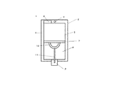
図1は、本発明の第一の実施態様としての医療用複室容器1の正面図であり、図2は、図1における医療用複室容器1の側面図である。医療用複室容器1はバッグ本体2を備え、バッグ本体2は外周縁にシール部6を設けることで薬剤収容室が形成される。シール部6は、図1における上方に、医療用複室容器1を支持台に吊り下げるための懸垂孔9を備える。薬剤収容室は、仕切部となる弱シール部7によって、第一の収容室4と第二の収容室5とに区切られ、それぞれの収容室には所定の薬液や薬剤等が収容される。第一の収容室4は、図1における下方に、輸液回路などを接続するための接続部13を備え、接続部13は、刺通針などを接続し、薬剤を排出するための排出口14を有し、排出口14への接続を阻止するための保護機構3を備える。第二収容画室5は、図1における上方に、薬剤の充填に使用される充填口8を備える。更に、バッグ本体2は、薬剤収容室及び/または弱シール部7外方に取っ手10を備え、取っ手10は、連結部材11によって保護機構3と連結される。   FIG. 1 is a front view of a medical multi-chamber container 1 as a first embodiment of the present invention, and FIG. 2 is a side view of the medical multi-chamber container 1 in FIG. The medical multi-chamber container 1 includes a bag main body 2, and the bag main body 2 is provided with a seal portion 6 on the outer peripheral edge to form a medicine storage chamber. The seal portion 6 includes a suspension hole 9 for suspending the medical multi-chamber container 1 on the support base at the upper side in FIG. The drug storage chamber is divided into a first storage chamber 4 and a second storage chamber 5 by a weak seal portion 7 serving as a partition, and a predetermined drug solution, drug, or the like is stored in each of the storage chambers. The first storage chamber 4 includes a connecting portion 13 for connecting an infusion circuit or the like below in FIG. 1, and the connecting portion 13 connects a piercing needle or the like and discharges a discharge port 14 for discharging a medicine. And a protection mechanism 3 for preventing connection to the discharge port 14. The second storage compartment 5 is provided with a filling port 8 used for filling medicine in the upper part in FIG. Further, the bag body 2 includes a handle 10 outside the drug storage chamber and / or the weak seal portion 7, and the handle 10 is connected to the protection mechanism 3 by a connecting member 11.

医療用複室容器1は、バッグ本体2が熱可塑性樹脂フィルムからなる袋体であって、外周縁にシール部6を設けることで、薬剤収容室を形成している。バッグ本体2は、シート状フィルムを重ねて、外周縁にシール部6を設けることで袋体としても良いし、筒状フィルムの開口端にシール部6を設けることで袋体としても良く、薬剤収容室を形成しうるものであれば、特に限定されるものではない。シール部6は、接着剤などで接着することで設けても良いし、熱溶着などで溶着することで設けても良く、特に限定されるものではない。
更に、薬剤収容室を仕切っている弱シール部7は、フィルムの上下の内面同士を熱接着させた構成である。弱シール部7をフィルムに熱シール可能な別のフィルムシートを介して互いに溶着した構成とすることも可能であり、引っ張ることで剥離させることができるものであれば、特に限定されるものではない。
熱可塑性樹脂フィルムとしては、ポリエチレン、ポリプロピレン、ポリエチレンテレフタレート、ポリエチレンテレナフタレート、ポリビニルアルコール、エチレンビニルアルコール共重合体、ポリ塩化ビニリデン、ナイロンなどの熱可塑性樹脂及びこれらの混合物から生成されるフィルムが挙げられる。また、これらの材料の積層体など医療用容器の材質として使用されるものであれば、特に限定はされないが、一般的には、ポリエチレン、ポリプロピレン、ポリエチレン及びポリプロピレンの混合物が好適に採用可能である。
The medical multi-chamber container 1 is a bag body in which the bag body 2 is made of a thermoplastic resin film, and a seal portion 6 is provided on the outer peripheral edge to form a medicine storage chamber. The bag body 2 may be a bag by stacking sheet films and providing a seal 6 on the outer periphery, or a bag by providing a seal 6 at the open end of the tubular film. There is no particular limitation as long as the storage chamber can be formed. The seal portion 6 may be provided by bonding with an adhesive or the like, or may be provided by welding by heat welding or the like, and is not particularly limited.
Furthermore, the weak seal part 7 which partitions off the chemical | medical agent storage chamber is the structure which heat-bonded the upper and lower inner surfaces of a film. The weak seal portion 7 may be configured to be welded to each other via another film sheet that can be heat sealed to the film, and is not particularly limited as long as it can be peeled off by pulling. .
Examples of the thermoplastic resin film include films produced from thermoplastic resins such as polyethylene, polypropylene, polyethylene terephthalate, polyethylene terephthalate, polyvinyl alcohol, ethylene vinyl alcohol copolymer, polyvinylidene chloride, nylon, and mixtures thereof. . In addition, the material is not particularly limited as long as it is used as a material for a medical container such as a laminate of these materials. In general, polyethylene, polypropylene, a mixture of polyethylene and polypropylene can be suitably used. .

懸垂孔9は、医療用複室容器1を支持台に吊り下げるためのものであり、設ける部位については、特に限定されるものではなく、図1における上方に設けても良いし、側方に設けても良い。使用時に薬剤を排出しやすい様に、排出口を下方にした状態を維持できるものであれば特に限定されるものではなく、好ましくは、接続部の対局に設けた構造である。   The suspension hole 9 is for suspending the medical multi-chamber container 1 on the support base, and the portion to be provided is not particularly limited, and may be provided above in FIG. It may be provided. The structure is not particularly limited as long as it can maintain the state in which the discharge port is positioned downward so that the medicine can be easily discharged during use, and is preferably a structure provided in the game of the connecting portion.

排出口14は、薬剤の排出するために設けられたもので、血液回路などを装着して薬剤の排出をすることができるものである。排出口14は、刺通針などを穿刺し、接続できるものであっても良いし、ニードルレス接続可能なものであっても良く、特に限定されるものではない。加えて、排出口14は、接続した刺通針などを介して、薬剤の充填を行うこともできる。   The discharge port 14 is provided for discharging a drug, and can discharge a drug by attaching a blood circuit or the like. The discharge port 14 may be pierced with a piercing needle or the like and may be connected, or may be connectable with a needleless connection, and is not particularly limited. In addition, the discharge port 14 can be filled with a medicine through a connected piercing needle or the like.

保護機構3は、排出口14に刺通針などを接続することを物理的に阻止するために設けられ、保護機構3が解除された際には、排出口14が露出し、刺通針などによる接続が可能となるものである。保護機構3は、物理的に排出口14との接続を阻止するものであれば、図5から図6に示される様に、接続部13全体を覆う様な形状であってもよいし、図7から図9に示される様に、排出口14を外部に露出させない様な形状であってもよい。   The protection mechanism 3 is provided to physically prevent a piercing needle or the like from being connected to the discharge port 14. When the protection mechanism 3 is released, the discharge port 14 is exposed and the puncture needle or the like is exposed. Connection by is possible. As long as the protection mechanism 3 physically blocks the connection with the discharge port 14, the protection mechanism 3 may have a shape that covers the entire connection portion 13 as shown in FIGS. 5 to 6. As shown in FIG. 7 to FIG. 9, the discharge port 14 may not be exposed to the outside.

充填口8は、薬剤の充填を行うためのものであり、薬剤を充填した後は、薬剤が漏れない様に閉じられる。充填口8を閉じる方法は、接着剤などで接着しても良いし、熱溶着などで溶着しても良く、特に限定されるものではない。
薬剤の充填については、排出口14及び充填口8を介して行っても良いし、第一収容室4及び第二収容画室5のそれぞれの側方に充填口を設け、側方から薬剤を充填しても良く、特に限定されるものではない。
The filling port 8 is for filling a medicine, and after filling the medicine, it is closed so that the medicine does not leak. The method of closing the filling port 8 may be bonded with an adhesive or the like, or may be welded with heat welding or the like, and is not particularly limited.
The filling of the medicine may be performed through the discharge port 14 and the filling port 8, or a filling port is provided in each side of the first storage chamber 4 and the second storage room 5, and the medicine is filled from the side. There is no particular limitation.

取っ手10は、バッグ本体2の収容室及び/または弱シール部外方に設けられる。本発明においては、図1及び図2で示される様に、バッグ本体2の両側にそれぞれ取っ手10a、10bとして設けられるが、取っ手10の数は、2個に限定されるものではなく、1個であっても良いし、3個以上であっても良く、引っ張ることで弱シール部7を剥離及び保護機構3の解除が行える数であれば、特に限定されるものではない。更に、取っ手10の形状は、引っ張ることで弱シール部7を剥離及び保護機構3の解除が行える形状であれば、特に限定されるものではない。
また、バッグ本体2には、取っ手10が設けられ、取っ手10はバッグ本体2と一体に作られても良いし、接着あるいは熱溶着などにより別途取り付けられても良い。
取っ手10を別途取り付ける場合、バッグ本体2と接着できるものであれば特に材質は問わないが、好ましくはバッグ本体2と熱溶着できる材質であり、更に好ましくは、熱可塑性樹脂フィルムである。
The handle 10 is provided outside the storage chamber of the bag body 2 and / or the weak seal portion. In the present invention, as shown in FIGS. 1 and 2, the handles 10a and 10b are provided on both sides of the bag body 2, respectively. However, the number of the handles 10 is not limited to two, but one It may be three or more, and is not particularly limited as long as it is a number capable of peeling the weak seal portion 7 and releasing the protection mechanism 3 by pulling. Furthermore, the shape of the handle 10 is not particularly limited as long as it is a shape capable of peeling the weak seal portion 7 and releasing the protection mechanism 3 by pulling.
The bag body 2 is provided with a handle 10, and the handle 10 may be made integrally with the bag body 2 or may be attached separately by adhesion or heat welding.
When the handle 10 is separately attached, the material is not particularly limited as long as it can be bonded to the bag body 2, but a material that can be thermally welded to the bag body 2 is preferable, and a thermoplastic resin film is more preferable.

連結部材11は、保護機構3と取っ手10とを連結するものであり、連結部材11は、保護機構3及び取っ手10と、別体としても良いし、どちらか一方あるいは両方と一体で成形されるものであっても良い。形状については、紐状、帯状、鎖状など特に形状は限定されない。材質についても、金属、樹脂、糸など特に限定されるものではないが、好ましくは、保護機構3及び取っ手10と接着できる素材であり、更に好ましくは、保護機構3及び取っ手10と熱溶着できる熱可塑性樹脂である。   The connecting member 11 connects the protection mechanism 3 and the handle 10, and the connecting member 11 may be separated from the protection mechanism 3 and the handle 10, or may be formed integrally with one or both of them. It may be a thing. Regarding the shape, the shape is not particularly limited, such as a string shape, a belt shape, or a chain shape. The material is not particularly limited, such as metal, resin, and thread, but is preferably a material that can be bonded to the protection mechanism 3 and the handle 10, and more preferably heat that can be thermally welded to the protection mechanism 3 and the handle 10. It is a plastic resin.

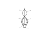
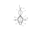
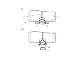
図3は、本発明の第一の実施態様としての医療用複室容器の連通前の側面図であり、医療用複室容器1を支持台のフック12に吊り下げ、取っ手10a及び10bを引っ張る前の状態を示している。図4は、本発明の第一の実施態様としての医療用複室容器の連通後の側面図であり、バッグ本体2においては、取っ手10a及び10bを引っ張った後の第一の収容室4及び第二の収容室5が連通し、且つ保護機構3が外れ、排出口14が露出した状態を示している。
使用に際しては、図3に示される様に、医療用複室容器1をフック12に吊り下げ、バッグ本体2の両側に設けられた取っ手10a及び10bを把持して、図中の矢印A−A´方向に引き離すように引っ張る。その結果、図4で示される様に、弱シール部7が剥離し、第一の収容室4及び第二の収容室5を連通させることができる。更には、取っ手10a及び10bは、それぞれ連結部材11a及び11bを介して、保護機構3と連結されており、取っ手10a及び10bを引っ張った際に、保護機構3が接続部13から外れることで、排出口14への接続が可能となる。
FIG. 3 is a side view of the medical multi-chamber container according to the first embodiment of the present invention before communication, in which the medical multi-chamber container 1 is suspended from the hook 12 of the support base and the handles 10a and 10b are pulled. The previous state is shown. FIG. 4 is a side view after communication of the medical multi-chamber container according to the first embodiment of the present invention. In the bag body 2, the first storage chamber 4 after pulling the handles 10a and 10b and A state is shown in which the second storage chamber 5 communicates, the protection mechanism 3 is detached, and the discharge port 14 is exposed.
In use, as shown in FIG. 3, the medical multi-chamber container 1 is suspended from the hook 12 and grips 10 a and 10 b provided on both sides of the bag body 2 are held, and arrows AA in the figure are shown. Pull it away in the ´ direction. As a result, as shown in FIG. 4, the weak seal portion 7 is peeled off, and the first storage chamber 4 and the second storage chamber 5 can be communicated with each other. Furthermore, the handles 10a and 10b are connected to the protection mechanism 3 via the connecting members 11a and 11b, respectively, and when the handles 10a and 10b are pulled, the protection mechanism 3 is detached from the connection portion 13, Connection to the outlet 14 is possible.

図5乃至図8には、本発明の第一乃至第四の実施態様としての医療用複室容器の接続部の拡大図である。第二乃至第四の実施態様としての医療用複室容器における外観は、図1及び図2で示される医療用複室容器と同様であり、保護機構3及び接続部13の形状が異なるものである。   5 to 8 are enlarged views of the connecting portion of the medical multi-chamber container according to the first to fourth embodiments of the present invention. The appearance of the medical multi-chamber container as the second to fourth embodiments is the same as that of the medical multi-chamber container shown in FIGS. 1 and 2, and the shapes of the protection mechanism 3 and the connecting portion 13 are different. is there.

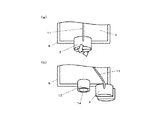
図5a及び図5bは、本発明の第一の実施態様としての医療用複室容器1の接続部13の拡大図である。図5aは、第一の収容室4及び第二の収容室5が連通する前の状態であり、保護機構3が接続部13を覆った状態を示している。図5bは、第一の収容室4及び第二の収容室5が連通した後の状態であり、保護機構3が接続部13から外れた状態を示している。保護機構3は、接続部13全体を覆う様に設けられ、連結部材11を介して、取っ手10と連結されている。連通前において、保護機構3は、接続部13全体を覆うことで排出口14への接続を阻止している。取っ手10を引っ張った際(連通操作)に、連結部材11によって連結された保護機構3が図中の矢印の方向に引っ張られ、保護機構3が接続部13から外れることで、排出口14への接続が可能となる。   5a and 5b are enlarged views of the connecting portion 13 of the medical multi-chamber container 1 according to the first embodiment of the present invention. FIG. 5 a shows a state before the first storage chamber 4 and the second storage chamber 5 communicate with each other, and shows a state in which the protection mechanism 3 covers the connection portion 13. FIG. 5 b shows a state after the first storage chamber 4 and the second storage chamber 5 communicate with each other, and shows a state where the protection mechanism 3 is detached from the connection portion 13. The protection mechanism 3 is provided so as to cover the entire connection portion 13 and is coupled to the handle 10 via the coupling member 11. Prior to communication, the protection mechanism 3 covers the entire connection portion 13 to prevent connection to the discharge port 14. When the handle 10 is pulled (communication operation), the protection mechanism 3 connected by the connection member 11 is pulled in the direction of the arrow in the figure, and the protection mechanism 3 is detached from the connection portion 13, so that Connection is possible.

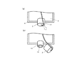
図6a及び図6bは、本発明の第二の実施態様としての医療用複室容器1の接続部13の拡大図である。図6aは、第一の収容室4及び第二の収容室5が連通する前の状態であり、保護機構3が接続部13を覆った状態を示している。図6bは、第一の収容室4及び第二の収容室5が連通した後の状態であり、保護機構3が接続部13から外れた状態を示している。保護機構3は、接続部13全体を覆う様に設けられ、連結部材11を介して、取っ手10と連結されている。連通前において、保護機構3は、接続部13全体を覆うことで排出口14への接続を阻止している。取っ手10を引っ張った際に、連結部材11によって連結された保護機構3が図中の矢印の方向に引っ張られ、保護機構3が接続部13から外れることで、排出口14への接続が可能となる。   6a and 6b are enlarged views of the connecting portion 13 of the medical multi-chamber container 1 according to the second embodiment of the present invention. FIG. 6 a shows a state before the first storage chamber 4 and the second storage chamber 5 communicate with each other, and shows a state where the protection mechanism 3 covers the connection portion 13. FIG. 6 b shows a state after the first storage chamber 4 and the second storage chamber 5 communicate with each other, and shows a state where the protection mechanism 3 is detached from the connection portion 13. The protection mechanism 3 is provided so as to cover the entire connection portion 13 and is coupled to the handle 10 via the coupling member 11. Prior to communication, the protection mechanism 3 covers the entire connection portion 13 to prevent connection to the discharge port 14. When the handle 10 is pulled, the protection mechanism 3 coupled by the coupling member 11 is pulled in the direction of the arrow in the figure, and the protection mechanism 3 is detached from the connection portion 13 so that the connection to the discharge port 14 is possible. Become.

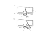
図7a及び図7bは、本発明の第三の実施態様としての医療用複室容器1の接続部13の拡大図である。図7aは、第一の収容室4及び第二の収容室5が連通する前の状態であり、保護機構3が排出口14の露出を阻止した状態を示している。図7bは、第一の収容室4及び第二の収容室5が連通した後の状態であり、保護機構3が排出口14から外れた状態を示している。保護機構3は、接続部13の排出口14を外部に露出させない様に設けられており、連結部材11を介して、取っ手10と連結されている。取っ手10を引っ張った際に、連結部材11によって連結された保護機構3が図中の矢印の方向に引っ張られ、保護機構3が外れ、排出口14が露出することで、排出口14への接続が可能となる。   7a and 7b are enlarged views of the connecting portion 13 of the medical multi-chamber container 1 according to the third embodiment of the present invention. FIG. 7 a shows a state before the first storage chamber 4 and the second storage chamber 5 communicate with each other, and shows a state where the protection mechanism 3 prevents the discharge port 14 from being exposed. FIG. 7 b shows a state after the first storage chamber 4 and the second storage chamber 5 communicate with each other, and shows a state where the protection mechanism 3 is detached from the discharge port 14. The protection mechanism 3 is provided so as not to expose the discharge port 14 of the connection portion 13 to the outside, and is connected to the handle 10 via the connecting member 11. When the handle 10 is pulled, the protection mechanism 3 connected by the connecting member 11 is pulled in the direction of the arrow in the figure, the protection mechanism 3 is detached, and the discharge port 14 is exposed, so that the connection to the discharge port 14 is established. Is possible.

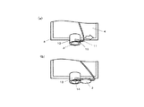
図8a及び図8bは、本発明の第四の実施態様としての医療用複室容器1の接続部13の拡大図である。図8aは、第一の収容室4及び第二の収容室5が連通する前の状態であり、保護機構3が排出口14の露出を阻止した状態を示している。図8bは、第一の収容室4及び第二の収容室5が連通した後の状態であり、保護機構3が排出口14から外れた状態を示している。接続部13の側方には側孔13が設けられている。保護機構3は、接続部13の排出口14を外部に露出させない様に設けられており、連結部材11を介して、取っ手10と連結されている。取っ手10を引っ張った際に、連結部材11によって連結された保護機構3が図中の矢印の方向に引っ張られ、保護機構3が側孔13の外方にスライドし、排出口14が露出することで、排出口14への接続が可能となる。   8a and 8b are enlarged views of the connecting portion 13 of the medical multi-chamber container 1 according to the fourth embodiment of the present invention. FIG. 8 a shows a state before the first storage chamber 4 and the second storage chamber 5 communicate with each other, and shows a state where the protection mechanism 3 prevents the discharge port 14 from being exposed. FIG. 8 b shows a state after the first storage chamber 4 and the second storage chamber 5 communicate with each other, and shows a state where the protection mechanism 3 is detached from the discharge port 14. Side holes 13 are provided on the sides of the connecting portion 13. The protection mechanism 3 is provided so as not to expose the discharge port 14 of the connection portion 13 to the outside, and is connected to the handle 10 via the connecting member 11. When the handle 10 is pulled, the protective mechanism 3 connected by the connecting member 11 is pulled in the direction of the arrow in the figure, and the protective mechanism 3 slides outward from the side hole 13 so that the discharge port 14 is exposed. Thus, connection to the discharge port 14 becomes possible.

図9a及び図9bは、本発明の第五の実施態様としての医療用複室容器1の接続部13の拡大図である。図9aは、第一の収容室4及び第二の収容室5が連通する前の状態であり、保護機構3が排出口14の露出を阻止した状態を示している。9bは、第一の収容室4及び第二の収容室5が連通した後の状態であり、保護機構3が排出口14から外れた状態を示している。保護機構3は、取っ手10を引っ張ることで解除可能なロック機構16を備えている。保護機構3は、接続部13の排出口14を外部に露出させない様に設けられており、ロック機構16は、連結部材11を介して、取っ手10と連結されている。取っ手10を引っ張った際に、保護機構3が外れ、排出口14が露出することで、排出口14への接続が可能となる。   9a and 9b are enlarged views of the connecting portion 13 of the medical multi-chamber container 1 according to the fifth embodiment of the present invention. FIG. 9 a shows a state before the first storage chamber 4 and the second storage chamber 5 communicate with each other, and shows a state where the protection mechanism 3 prevents the discharge port 14 from being exposed. 9b is a state after the first storage chamber 4 and the second storage chamber 5 communicate with each other, and shows a state in which the protection mechanism 3 is detached from the discharge port 14. The protection mechanism 3 includes a lock mechanism 16 that can be released by pulling the handle 10. The protection mechanism 3 is provided so as not to expose the discharge port 14 of the connection portion 13 to the outside, and the lock mechanism 16 is coupled to the handle 10 via the coupling member 11. When the handle 10 is pulled, the protection mechanism 3 is detached and the discharge port 14 is exposed, so that the connection to the discharge port 14 becomes possible.

保護機構3の形状は、図5及び図6に示される様に、接続部13全体を覆うものであっても良いし、図7及び図9に示される様に、排出口14を外部に露出させないものであっても良い。
更に、接続部13全体を覆う保護機構3については、図5で示される様に、引っ張ることで二つに分離し、解除される形状であっても良いし、引っ張ることで開裂し、解除される形状であっても良い。
更に、排出口14を外部に露出させない保護機構3については、図7で示される様に下方に引っ張る形状であっても良いし、図8で示される様に横方向にスライドさせる形状であっても良い。図8で示される様な横方向にスライドさせる形状においては、保護機構3を接続部13から完全に取り外せる形状であっても良いし、スライド後、接続部13に係合した状態で取り外せない形状であっても良い。
また、保護機構3は、図9で示される様に保護機構3に設けられたロック機構18を引っ張ることで解除される形状であっても良く、接続部13の接続阻止が解除された際は、保護機構3を接続部13から分離される形状であっても良いし、保護機構3の一部が接続部13と連結され、排出口14を露出させるだけの形状であっても良い。
また、これ以外の形状であっても同様の働きをするものであれば特に限定されるものではない。
The shape of the protection mechanism 3 may cover the entire connection portion 13 as shown in FIGS. 5 and 6, and the discharge port 14 is exposed to the outside as shown in FIGS. 7 and 9. It may not be allowed.
Further, as shown in FIG. 5, the protection mechanism 3 covering the entire connecting portion 13 may be separated into two parts by being pulled and released, or may be broken and released by being pulled. It may be a shape.
Further, the protection mechanism 3 that does not expose the discharge port 14 to the outside may have a shape that pulls downward as shown in FIG. 7 or a shape that slides in the horizontal direction as shown in FIG. Also good. The shape that is slid in the lateral direction as shown in FIG. 8 may be a shape that allows the protection mechanism 3 to be completely removed from the connection portion 13, or a shape that cannot be removed after being slid and engaged with the connection portion 13. It may be.
Further, the protection mechanism 3 may have a shape that is released by pulling the lock mechanism 18 provided in the protection mechanism 3 as shown in FIG. 9. When the connection blocking of the connection portion 13 is released, The protection mechanism 3 may be separated from the connection portion 13, or a part of the protection mechanism 3 may be connected to the connection portion 13 and the discharge port 14 may be exposed.
Moreover, even if it is a shape other than this, if it acts similarly, it will not specifically limit.

1:医療用複室容器、2:バッグ本体、3:保護機構、4:第一の収容室、5:第二の収容室、6:シール部、7:弱シール部、8:充填口、9:懸垂孔、10:取っ手、11:連結部材、12:フック、13:接続部、14:排出口、15:側孔、16:ロック機構 1: medical multi-chamber container, 2: bag body, 3: protection mechanism, 4: first storage chamber, 5: second storage chamber, 6: seal portion, 7: weak seal portion, 8: filling port, 9: suspension hole, 10: handle, 11: coupling member, 12: hook, 13: connection part, 14: outlet, 15: side hole, 16: lock mechanism

Claims (5)

薬剤を収容可能な薬剤収容室を有するバッグ本体と、
前記薬剤収容室内の薬剤を排出可能な排出口を有する接続部を備え、前記バッグ本体には、薬剤収容室を複数の収容室に区画する弱シール部が設けられた薬剤バッグにおいて、
前記収容室及び/または前記弱シール部外方に取っ手を有し、
前記接続部に、通常は前記排出口への接続を阻止する保護機構を有し、
前記保護機構が、連結部材により前記取っ手と連結され、
前記取っ手を前記バッグ本体の外方向に引っ張った際に、前記弱シール部が剥離し前記複数の収容室が連通すると共に、前記保護機構が前記連結部材により前記取っ手と連結されているため、前記複数の収容室が連通するのと同時に前記保護機構が前記排出口から外れることを特徴とする医療用複室容器。
A bag body having a medicine storage chamber capable of containing a medicine;
In the drug bag provided with a connection portion having a discharge port capable of discharging the drug in the drug storage chamber, the bag body is provided with a weak seal portion that divides the drug storage chamber into a plurality of storage chambers,
Having a handle outside the storage chamber and / or the weak seal portion,
The connection portion has a protection mechanism that normally prevents connection to the outlet,
The protective mechanism is connected to the handle by a connecting member;
When the handle is pulled outward of the bag body, the weak seal portion is peeled off and the plurality of storage chambers communicate with each other, and the protection mechanism is connected to the handle by the connecting member. The medical multi-chamber container, wherein the protection mechanism is detached from the discharge port at the same time as the plurality of storage chambers communicate with each other .
前記保護機構が、前記接続部を覆うように取り付けられていることを特徴とする請求項1に記載の医療用複室容器。 The medical multi-chamber container according to claim 1, wherein the protection mechanism is attached so as to cover the connection portion. 前記保護機構が、前記排出口の露出を阻止するように取り付けられていることを特徴とする請求項1に記載の医療用複室容器。 The medical multi-chamber container according to claim 1, wherein the protection mechanism is attached so as to prevent the discharge port from being exposed. 前記取っ手が、前記収容室の中央部よりも前記弱シール部の近傍に設けられていることを特徴とする請求項1乃至3に記載の医療用複室容器。 The medical multi-chamber container according to claim 1, wherein the handle is provided in the vicinity of the weak seal portion rather than a central portion of the storage chamber. 前記取っ手が、前記弱シール部上に設けられていることを特徴とする請求項1乃至4に記載の医療用複室容器。 The medical multi-chamber container according to claim 1, wherein the handle is provided on the weak seal portion.
JP2011005855A 2011-01-14 2011-01-14 Medical multi-chamber container Active JP5772000B2 (en)

Priority Applications (1)

Application Number Priority Date Filing Date Title
JP2011005855A JP5772000B2 (en) 2011-01-14 2011-01-14 Medical multi-chamber container

Applications Claiming Priority (1)

Application Number Priority Date Filing Date Title
JP2011005855A JP5772000B2 (en) 2011-01-14 2011-01-14 Medical multi-chamber container

Publications (2)

Publication Number Publication Date
JP2012143485A JP2012143485A (en) 2012-08-02
JP5772000B2 true JP5772000B2 (en) 2015-09-02

Family

ID=46787688

Family Applications (1)

Application Number Title Priority Date Filing Date
JP2011005855A Active JP5772000B2 (en) 2011-01-14 2011-01-14 Medical multi-chamber container

Country Status (1)

Country Link
JP (1) JP5772000B2 (en)

Family Cites Families (2)

* Cited by examiner, † Cited by third party
Publication number Priority date Publication date Assignee Title
DE4447626C5 (en) * 1994-03-29 2007-01-25 Fresenius Ag Medical multi-chamber bag
JP4619274B2 (en) * 2005-11-18 2011-01-26 株式会社大塚製薬工場 Medical multi-chamber container

Also Published As

Publication number Publication date
JP2012143485A (en) 2012-08-02

Similar Documents

Publication Publication Date Title
JP2828505B2 (en) Flexible container and method of forming the same
EP1838272B1 (en) Medical liquid container and preparation-containing medical liquid container
TWI453009B (en) Multi-chamber bag
JPH11263354A (en) Packaging bag
JP5772000B2 (en) Medical multi-chamber container
JP2014023772A (en) Dual-chamber container
JP2007217052A (en) Packaging bag having spout
JP4708234B2 (en) Medical multi-chamber container
JP2007260252A (en) Medical container
JP4649854B2 (en) Drug bag
JP2008200367A (en) Medical container
JP2008029529A (en) Medical multi-chamber container
JP2009195470A (en) Medical multi-chamber container
JP2007130358A (en) Medical multi-chamber container
JP5078370B2 (en) Medical container
JP2009160266A (en) Medical multi-chamber container
JPWO2007055355A1 (en) Multi-chamber container
JP2005187030A (en) Flexible multi-chamber container
JP2016131577A (en) Medical multi-chamber container
JP4476598B2 (en) Multi-chamber infusion container and multi-chamber infusion container with drug
JP3932427B2 (en) Manufacturing method of medical multi-chamber container
JP2020503914A (en) Medical bag with two compartments and tabs
JP4609791B2 (en) Multi-chamber container
JP5446914B2 (en) Medical multi-chamber container
JP2005211481A (en) Medical double-chamber vessel

Legal Events

Date Code Title Description
A621 Written request for application examination

Free format text: JAPANESE INTERMEDIATE CODE: A621

Effective date: 20131220

A131 Notification of reasons for refusal

Free format text: JAPANESE INTERMEDIATE CODE: A131

Effective date: 20140909

A977 Report on retrieval

Free format text: JAPANESE INTERMEDIATE CODE: A971007

Effective date: 20140912

A521 Written amendment

Free format text: JAPANESE INTERMEDIATE CODE: A523

Effective date: 20141110

TRDD Decision of grant or rejection written
A01 Written decision to grant a patent or to grant a registration (utility model)

Free format text: JAPANESE INTERMEDIATE CODE: A01

Effective date: 20150602

A61 First payment of annual fees (during grant procedure)

Free format text: JAPANESE INTERMEDIATE CODE: A61

Effective date: 20150615

R150 Certificate of patent or registration of utility model

Ref document number: 5772000

Country of ref document: JP

Free format text: JAPANESE INTERMEDIATE CODE: R150

R250 Receipt of annual fees

Free format text: JAPANESE INTERMEDIATE CODE: R250

R250 Receipt of annual fees

Free format text: JAPANESE INTERMEDIATE CODE: R250