JP5771277B2 - System and method for fixation or fixation of compression implants using bone - Google Patents
System and method for fixation or fixation of compression implants using bone Download PDFInfo
- Publication number
- JP5771277B2 JP5771277B2 JP2013532916A JP2013532916A JP5771277B2 JP 5771277 B2 JP5771277 B2 JP 5771277B2 JP 2013532916 A JP2013532916 A JP 2013532916A JP 2013532916 A JP2013532916 A JP 2013532916A JP 5771277 B2 JP5771277 B2 JP 5771277B2
- Authority
- JP
- Japan
- Prior art keywords
- bone
- anchor
- assembly
- implant structure
- region
- Prior art date
- Legal status (The legal status is an assumption and is not a legal conclusion. Google has not performed a legal analysis and makes no representation as to the accuracy of the status listed.)
- Active
Links
Images


Classifications
-
- A—HUMAN NECESSITIES
- A61—MEDICAL OR VETERINARY SCIENCE; HYGIENE
- A61B—DIAGNOSIS; SURGERY; IDENTIFICATION
- A61B17/00—Surgical instruments, devices or methods, e.g. tourniquets
- A61B17/16—Bone cutting, breaking or removal means other than saws, e.g. Osteoclasts; Drills or chisels for bones; Trepans
- A61B17/1659—Surgical rasps, files, planes, or scrapers
-
- A—HUMAN NECESSITIES
- A61—MEDICAL OR VETERINARY SCIENCE; HYGIENE
- A61B—DIAGNOSIS; SURGERY; IDENTIFICATION
- A61B17/00—Surgical instruments, devices or methods, e.g. tourniquets
- A61B17/16—Bone cutting, breaking or removal means other than saws, e.g. Osteoclasts; Drills or chisels for bones; Trepans
- A61B17/17—Guides or aligning means for drills, mills, pins or wires
- A61B17/1739—Guides or aligning means for drills, mills, pins or wires specially adapted for particular parts of the body
- A61B17/1757—Guides or aligning means for drills, mills, pins or wires specially adapted for particular parts of the body for the spine
-
- A—HUMAN NECESSITIES
- A61—MEDICAL OR VETERINARY SCIENCE; HYGIENE
- A61B—DIAGNOSIS; SURGERY; IDENTIFICATION
- A61B17/00—Surgical instruments, devices or methods, e.g. tourniquets
- A61B17/16—Bone cutting, breaking or removal means other than saws, e.g. Osteoclasts; Drills or chisels for bones; Trepans
- A61B17/1613—Component parts
- A61B17/1615—Drill bits, i.e. rotating tools extending from a handpiece to contact the worked material
-
- A—HUMAN NECESSITIES
- A61—MEDICAL OR VETERINARY SCIENCE; HYGIENE
- A61B—DIAGNOSIS; SURGERY; IDENTIFICATION
- A61B17/00—Surgical instruments, devices or methods, e.g. tourniquets
- A61B17/16—Bone cutting, breaking or removal means other than saws, e.g. Osteoclasts; Drills or chisels for bones; Trepans
- A61B17/1662—Bone cutting, breaking or removal means other than saws, e.g. Osteoclasts; Drills or chisels for bones; Trepans for particular parts of the body
- A61B17/1664—Bone cutting, breaking or removal means other than saws, e.g. Osteoclasts; Drills or chisels for bones; Trepans for particular parts of the body for the hip
-
- A—HUMAN NECESSITIES
- A61—MEDICAL OR VETERINARY SCIENCE; HYGIENE
- A61B—DIAGNOSIS; SURGERY; IDENTIFICATION
- A61B17/00—Surgical instruments, devices or methods, e.g. tourniquets
- A61B17/16—Bone cutting, breaking or removal means other than saws, e.g. Osteoclasts; Drills or chisels for bones; Trepans
- A61B17/1662—Bone cutting, breaking or removal means other than saws, e.g. Osteoclasts; Drills or chisels for bones; Trepans for particular parts of the body
- A61B17/1671—Bone cutting, breaking or removal means other than saws, e.g. Osteoclasts; Drills or chisels for bones; Trepans for particular parts of the body for the spine
-
- A—HUMAN NECESSITIES
- A61—MEDICAL OR VETERINARY SCIENCE; HYGIENE
- A61B—DIAGNOSIS; SURGERY; IDENTIFICATION
- A61B17/00—Surgical instruments, devices or methods, e.g. tourniquets
- A61B17/56—Surgical instruments or methods for treatment of bones or joints; Devices specially adapted therefor
- A61B17/58—Surgical instruments or methods for treatment of bones or joints; Devices specially adapted therefor for osteosynthesis, e.g. bone plates, screws, setting implements or the like
- A61B17/68—Internal fixation devices, including fasteners and spinal fixators, even if a part thereof projects from the skin
- A61B17/686—Plugs, i.e. elements forming interface between bone hole and implant or fastener, e.g. screw
-
- A—HUMAN NECESSITIES
- A61—MEDICAL OR VETERINARY SCIENCE; HYGIENE
- A61B—DIAGNOSIS; SURGERY; IDENTIFICATION
- A61B17/00—Surgical instruments, devices or methods, e.g. tourniquets
- A61B17/56—Surgical instruments or methods for treatment of bones or joints; Devices specially adapted therefor
- A61B17/58—Surgical instruments or methods for treatment of bones or joints; Devices specially adapted therefor for osteosynthesis, e.g. bone plates, screws, setting implements or the like
- A61B17/68—Internal fixation devices, including fasteners and spinal fixators, even if a part thereof projects from the skin
- A61B17/70—Spinal positioners or stabilisers ; Bone stabilisers comprising fluid filler in an implant
- A61B17/7055—Spinal positioners or stabilisers ; Bone stabilisers comprising fluid filler in an implant connected to sacrum, pelvis or skull
-
- A—HUMAN NECESSITIES
- A61—MEDICAL OR VETERINARY SCIENCE; HYGIENE
- A61B—DIAGNOSIS; SURGERY; IDENTIFICATION
- A61B17/00—Surgical instruments, devices or methods, e.g. tourniquets
- A61B17/56—Surgical instruments or methods for treatment of bones or joints; Devices specially adapted therefor
- A61B17/58—Surgical instruments or methods for treatment of bones or joints; Devices specially adapted therefor for osteosynthesis, e.g. bone plates, screws, setting implements or the like
- A61B17/68—Internal fixation devices, including fasteners and spinal fixators, even if a part thereof projects from the skin
- A61B17/84—Fasteners therefor or fasteners being internal fixation devices
- A61B17/86—Pins or screws or threaded wires; nuts therefor
- A61B17/8625—Shanks, i.e. parts contacting bone tissue
- A61B17/863—Shanks, i.e. parts contacting bone tissue with thread interrupted or changing its form along shank, other than constant taper
-
- A—HUMAN NECESSITIES
- A61—MEDICAL OR VETERINARY SCIENCE; HYGIENE
- A61B—DIAGNOSIS; SURGERY; IDENTIFICATION
- A61B17/00—Surgical instruments, devices or methods, e.g. tourniquets
- A61B17/56—Surgical instruments or methods for treatment of bones or joints; Devices specially adapted therefor
- A61B17/58—Surgical instruments or methods for treatment of bones or joints; Devices specially adapted therefor for osteosynthesis, e.g. bone plates, screws, setting implements or the like
- A61B17/68—Internal fixation devices, including fasteners and spinal fixators, even if a part thereof projects from the skin
- A61B17/84—Fasteners therefor or fasteners being internal fixation devices
- A61B17/86—Pins or screws or threaded wires; nuts therefor
- A61B17/864—Pins or screws or threaded wires; nuts therefor hollow, e.g. with socket or cannulated
-
- A—HUMAN NECESSITIES
- A61—MEDICAL OR VETERINARY SCIENCE; HYGIENE
- A61B—DIAGNOSIS; SURGERY; IDENTIFICATION
- A61B17/00—Surgical instruments, devices or methods, e.g. tourniquets
- A61B17/56—Surgical instruments or methods for treatment of bones or joints; Devices specially adapted therefor
- A61B17/58—Surgical instruments or methods for treatment of bones or joints; Devices specially adapted therefor for osteosynthesis, e.g. bone plates, screws, setting implements or the like
- A61B17/68—Internal fixation devices, including fasteners and spinal fixators, even if a part thereof projects from the skin
- A61B17/84—Fasteners therefor or fasteners being internal fixation devices
- A61B17/86—Pins or screws or threaded wires; nuts therefor
- A61B17/866—Material or manufacture
-
- A—HUMAN NECESSITIES
- A61—MEDICAL OR VETERINARY SCIENCE; HYGIENE
- A61B—DIAGNOSIS; SURGERY; IDENTIFICATION
- A61B17/00—Surgical instruments, devices or methods, e.g. tourniquets
- A61B17/56—Surgical instruments or methods for treatment of bones or joints; Devices specially adapted therefor
- A61B17/58—Surgical instruments or methods for treatment of bones or joints; Devices specially adapted therefor for osteosynthesis, e.g. bone plates, screws, setting implements or the like
- A61B17/68—Internal fixation devices, including fasteners and spinal fixators, even if a part thereof projects from the skin
- A61B17/84—Fasteners therefor or fasteners being internal fixation devices
- A61B17/86—Pins or screws or threaded wires; nuts therefor
- A61B17/8665—Nuts
-
- A—HUMAN NECESSITIES
- A61—MEDICAL OR VETERINARY SCIENCE; HYGIENE
- A61B—DIAGNOSIS; SURGERY; IDENTIFICATION
- A61B17/00—Surgical instruments, devices or methods, e.g. tourniquets
- A61B17/56—Surgical instruments or methods for treatment of bones or joints; Devices specially adapted therefor
- A61B17/58—Surgical instruments or methods for treatment of bones or joints; Devices specially adapted therefor for osteosynthesis, e.g. bone plates, screws, setting implements or the like
- A61B17/68—Internal fixation devices, including fasteners and spinal fixators, even if a part thereof projects from the skin
- A61B17/84—Fasteners therefor or fasteners being internal fixation devices
- A61B17/86—Pins or screws or threaded wires; nuts therefor
- A61B17/8685—Pins or screws or threaded wires; nuts therefor comprising multiple separate parts
-
- A—HUMAN NECESSITIES
- A61—MEDICAL OR VETERINARY SCIENCE; HYGIENE
- A61B—DIAGNOSIS; SURGERY; IDENTIFICATION
- A61B17/00—Surgical instruments, devices or methods, e.g. tourniquets
- A61B17/56—Surgical instruments or methods for treatment of bones or joints; Devices specially adapted therefor
- A61B17/58—Surgical instruments or methods for treatment of bones or joints; Devices specially adapted therefor for osteosynthesis, e.g. bone plates, screws, setting implements or the like
- A61B17/68—Internal fixation devices, including fasteners and spinal fixators, even if a part thereof projects from the skin
- A61B17/84—Fasteners therefor or fasteners being internal fixation devices
- A61B17/86—Pins or screws or threaded wires; nuts therefor
- A61B17/8695—Washers
-
- A—HUMAN NECESSITIES
- A61—MEDICAL OR VETERINARY SCIENCE; HYGIENE
- A61B—DIAGNOSIS; SURGERY; IDENTIFICATION
- A61B17/00—Surgical instruments, devices or methods, e.g. tourniquets
- A61B17/56—Surgical instruments or methods for treatment of bones or joints; Devices specially adapted therefor
- A61B17/58—Surgical instruments or methods for treatment of bones or joints; Devices specially adapted therefor for osteosynthesis, e.g. bone plates, screws, setting implements or the like
- A61B17/88—Osteosynthesis instruments; Methods or means for implanting or extracting internal or external fixation devices
- A61B17/8897—Guide wires or guide pins
-
- A—HUMAN NECESSITIES
- A61—MEDICAL OR VETERINARY SCIENCE; HYGIENE
- A61F—FILTERS IMPLANTABLE INTO BLOOD VESSELS; PROSTHESES; DEVICES PROVIDING PATENCY TO, OR PREVENTING COLLAPSING OF, TUBULAR STRUCTURES OF THE BODY, e.g. STENTS; ORTHOPAEDIC, NURSING OR CONTRACEPTIVE DEVICES; FOMENTATION; TREATMENT OR PROTECTION OF EYES OR EARS; BANDAGES, DRESSINGS OR ABSORBENT PADS; FIRST-AID KITS
- A61F2/00—Filters implantable into blood vessels; Prostheses, i.e. artificial substitutes or replacements for parts of the body; Appliances for connecting them with the body; Devices providing patency to, or preventing collapsing of, tubular structures of the body, e.g. stents
- A61F2/02—Prostheses implantable into the body
- A61F2/30—Joints
- A61F2/44—Joints for the spine, e.g. vertebrae, spinal discs
- A61F2/4455—Joints for the spine, e.g. vertebrae, spinal discs for the fusion of spinal bodies, e.g. intervertebral fusion of adjacent spinal bodies, e.g. fusion cages
-
- A—HUMAN NECESSITIES
- A61—MEDICAL OR VETERINARY SCIENCE; HYGIENE
- A61B—DIAGNOSIS; SURGERY; IDENTIFICATION
- A61B17/00—Surgical instruments, devices or methods, e.g. tourniquets
- A61B17/56—Surgical instruments or methods for treatment of bones or joints; Devices specially adapted therefor
- A61B17/58—Surgical instruments or methods for treatment of bones or joints; Devices specially adapted therefor for osteosynthesis, e.g. bone plates, screws, setting implements or the like
- A61B17/68—Internal fixation devices, including fasteners and spinal fixators, even if a part thereof projects from the skin
- A61B17/683—Internal fixation devices, including fasteners and spinal fixators, even if a part thereof projects from the skin comprising bone transfixation elements, e.g. bolt with a distal cooperating element such as a nut
-
- A—HUMAN NECESSITIES
- A61—MEDICAL OR VETERINARY SCIENCE; HYGIENE
- A61B—DIAGNOSIS; SURGERY; IDENTIFICATION
- A61B17/00—Surgical instruments, devices or methods, e.g. tourniquets
- A61B17/56—Surgical instruments or methods for treatment of bones or joints; Devices specially adapted therefor
- A61B17/58—Surgical instruments or methods for treatment of bones or joints; Devices specially adapted therefor for osteosynthesis, e.g. bone plates, screws, setting implements or the like
- A61B17/88—Osteosynthesis instruments; Methods or means for implanting or extracting internal or external fixation devices
- A61B17/8875—Screwdrivers, spanners or wrenches
- A61B17/8886—Screwdrivers, spanners or wrenches holding the screw head
- A61B17/8891—Screwdrivers, spanners or wrenches holding the screw head at its periphery
-
- A—HUMAN NECESSITIES
- A61—MEDICAL OR VETERINARY SCIENCE; HYGIENE
- A61B—DIAGNOSIS; SURGERY; IDENTIFICATION
- A61B17/00—Surgical instruments, devices or methods, e.g. tourniquets
- A61B17/56—Surgical instruments or methods for treatment of bones or joints; Devices specially adapted therefor
- A61B17/58—Surgical instruments or methods for treatment of bones or joints; Devices specially adapted therefor for osteosynthesis, e.g. bone plates, screws, setting implements or the like
- A61B17/68—Internal fixation devices, including fasteners and spinal fixators, even if a part thereof projects from the skin
- A61B2017/681—Alignment, compression, or distraction mechanisms
-
- A—HUMAN NECESSITIES
- A61—MEDICAL OR VETERINARY SCIENCE; HYGIENE
- A61B—DIAGNOSIS; SURGERY; IDENTIFICATION
- A61B17/00—Surgical instruments, devices or methods, e.g. tourniquets
- A61B17/56—Surgical instruments or methods for treatment of bones or joints; Devices specially adapted therefor
- A61B17/58—Surgical instruments or methods for treatment of bones or joints; Devices specially adapted therefor for osteosynthesis, e.g. bone plates, screws, setting implements or the like
- A61B17/68—Internal fixation devices, including fasteners and spinal fixators, even if a part thereof projects from the skin
- A61B17/84—Fasteners therefor or fasteners being internal fixation devices
- A61B17/86—Pins or screws or threaded wires; nuts therefor
- A61B17/8665—Nuts
- A61B2017/867—Nuts with integral locking or clamping means
- A61B2017/8675—Nuts with integral locking or clamping means clamping effect due to tapering, e.g. conical thread
-
- A—HUMAN NECESSITIES
- A61—MEDICAL OR VETERINARY SCIENCE; HYGIENE
- A61F—FILTERS IMPLANTABLE INTO BLOOD VESSELS; PROSTHESES; DEVICES PROVIDING PATENCY TO, OR PREVENTING COLLAPSING OF, TUBULAR STRUCTURES OF THE BODY, e.g. STENTS; ORTHOPAEDIC, NURSING OR CONTRACEPTIVE DEVICES; FOMENTATION; TREATMENT OR PROTECTION OF EYES OR EARS; BANDAGES, DRESSINGS OR ABSORBENT PADS; FIRST-AID KITS
- A61F2/00—Filters implantable into blood vessels; Prostheses, i.e. artificial substitutes or replacements for parts of the body; Appliances for connecting them with the body; Devices providing patency to, or preventing collapsing of, tubular structures of the body, e.g. stents
- A61F2/0077—Special surfaces of prostheses, e.g. for improving ingrowth
-
- A—HUMAN NECESSITIES
- A61—MEDICAL OR VETERINARY SCIENCE; HYGIENE
- A61F—FILTERS IMPLANTABLE INTO BLOOD VESSELS; PROSTHESES; DEVICES PROVIDING PATENCY TO, OR PREVENTING COLLAPSING OF, TUBULAR STRUCTURES OF THE BODY, e.g. STENTS; ORTHOPAEDIC, NURSING OR CONTRACEPTIVE DEVICES; FOMENTATION; TREATMENT OR PROTECTION OF EYES OR EARS; BANDAGES, DRESSINGS OR ABSORBENT PADS; FIRST-AID KITS
- A61F2/00—Filters implantable into blood vessels; Prostheses, i.e. artificial substitutes or replacements for parts of the body; Appliances for connecting them with the body; Devices providing patency to, or preventing collapsing of, tubular structures of the body, e.g. stents
- A61F2/02—Prostheses implantable into the body
- A61F2/28—Bones
-
- A—HUMAN NECESSITIES
- A61—MEDICAL OR VETERINARY SCIENCE; HYGIENE
- A61F—FILTERS IMPLANTABLE INTO BLOOD VESSELS; PROSTHESES; DEVICES PROVIDING PATENCY TO, OR PREVENTING COLLAPSING OF, TUBULAR STRUCTURES OF THE BODY, e.g. STENTS; ORTHOPAEDIC, NURSING OR CONTRACEPTIVE DEVICES; FOMENTATION; TREATMENT OR PROTECTION OF EYES OR EARS; BANDAGES, DRESSINGS OR ABSORBENT PADS; FIRST-AID KITS
- A61F2/00—Filters implantable into blood vessels; Prostheses, i.e. artificial substitutes or replacements for parts of the body; Appliances for connecting them with the body; Devices providing patency to, or preventing collapsing of, tubular structures of the body, e.g. stents
- A61F2/02—Prostheses implantable into the body
- A61F2/30—Joints
- A61F2/30767—Special external or bone-contacting surface, e.g. coating for improving bone ingrowth
-
- A—HUMAN NECESSITIES
- A61—MEDICAL OR VETERINARY SCIENCE; HYGIENE
- A61F—FILTERS IMPLANTABLE INTO BLOOD VESSELS; PROSTHESES; DEVICES PROVIDING PATENCY TO, OR PREVENTING COLLAPSING OF, TUBULAR STRUCTURES OF THE BODY, e.g. STENTS; ORTHOPAEDIC, NURSING OR CONTRACEPTIVE DEVICES; FOMENTATION; TREATMENT OR PROTECTION OF EYES OR EARS; BANDAGES, DRESSINGS OR ABSORBENT PADS; FIRST-AID KITS
- A61F2/00—Filters implantable into blood vessels; Prostheses, i.e. artificial substitutes or replacements for parts of the body; Appliances for connecting them with the body; Devices providing patency to, or preventing collapsing of, tubular structures of the body, e.g. stents
- A61F2/02—Prostheses implantable into the body
- A61F2/30—Joints
- A61F2/44—Joints for the spine, e.g. vertebrae, spinal discs
- A61F2/4455—Joints for the spine, e.g. vertebrae, spinal discs for the fusion of spinal bodies, e.g. intervertebral fusion of adjacent spinal bodies, e.g. fusion cages
- A61F2/4465—Joints for the spine, e.g. vertebrae, spinal discs for the fusion of spinal bodies, e.g. intervertebral fusion of adjacent spinal bodies, e.g. fusion cages having a circular or kidney shaped cross-section substantially perpendicular to the axis of the spine
-
- A—HUMAN NECESSITIES
- A61—MEDICAL OR VETERINARY SCIENCE; HYGIENE
- A61F—FILTERS IMPLANTABLE INTO BLOOD VESSELS; PROSTHESES; DEVICES PROVIDING PATENCY TO, OR PREVENTING COLLAPSING OF, TUBULAR STRUCTURES OF THE BODY, e.g. STENTS; ORTHOPAEDIC, NURSING OR CONTRACEPTIVE DEVICES; FOMENTATION; TREATMENT OR PROTECTION OF EYES OR EARS; BANDAGES, DRESSINGS OR ABSORBENT PADS; FIRST-AID KITS
- A61F2/00—Filters implantable into blood vessels; Prostheses, i.e. artificial substitutes or replacements for parts of the body; Appliances for connecting them with the body; Devices providing patency to, or preventing collapsing of, tubular structures of the body, e.g. stents
- A61F2/02—Prostheses implantable into the body
- A61F2/30—Joints
- A61F2/44—Joints for the spine, e.g. vertebrae, spinal discs
- A61F2/4455—Joints for the spine, e.g. vertebrae, spinal discs for the fusion of spinal bodies, e.g. intervertebral fusion of adjacent spinal bodies, e.g. fusion cages
- A61F2/447—Joints for the spine, e.g. vertebrae, spinal discs for the fusion of spinal bodies, e.g. intervertebral fusion of adjacent spinal bodies, e.g. fusion cages substantially parallelepipedal, e.g. having a rectangular or trapezoidal cross-section
-
- A—HUMAN NECESSITIES
- A61—MEDICAL OR VETERINARY SCIENCE; HYGIENE
- A61F—FILTERS IMPLANTABLE INTO BLOOD VESSELS; PROSTHESES; DEVICES PROVIDING PATENCY TO, OR PREVENTING COLLAPSING OF, TUBULAR STRUCTURES OF THE BODY, e.g. STENTS; ORTHOPAEDIC, NURSING OR CONTRACEPTIVE DEVICES; FOMENTATION; TREATMENT OR PROTECTION OF EYES OR EARS; BANDAGES, DRESSINGS OR ABSORBENT PADS; FIRST-AID KITS
- A61F2/00—Filters implantable into blood vessels; Prostheses, i.e. artificial substitutes or replacements for parts of the body; Appliances for connecting them with the body; Devices providing patency to, or preventing collapsing of, tubular structures of the body, e.g. stents
- A61F2/02—Prostheses implantable into the body
- A61F2/30—Joints
- A61F2002/30001—Additional features of subject-matter classified in A61F2/28, A61F2/30 and subgroups thereof
- A61F2002/30003—Material related properties of the prosthesis or of a coating on the prosthesis
- A61F2002/3006—Properties of materials and coating materials
- A61F2002/30062—(bio)absorbable, biodegradable, bioerodable, (bio)resorbable, resorptive
-
- A—HUMAN NECESSITIES
- A61—MEDICAL OR VETERINARY SCIENCE; HYGIENE
- A61F—FILTERS IMPLANTABLE INTO BLOOD VESSELS; PROSTHESES; DEVICES PROVIDING PATENCY TO, OR PREVENTING COLLAPSING OF, TUBULAR STRUCTURES OF THE BODY, e.g. STENTS; ORTHOPAEDIC, NURSING OR CONTRACEPTIVE DEVICES; FOMENTATION; TREATMENT OR PROTECTION OF EYES OR EARS; BANDAGES, DRESSINGS OR ABSORBENT PADS; FIRST-AID KITS
- A61F2/00—Filters implantable into blood vessels; Prostheses, i.e. artificial substitutes or replacements for parts of the body; Appliances for connecting them with the body; Devices providing patency to, or preventing collapsing of, tubular structures of the body, e.g. stents
- A61F2/02—Prostheses implantable into the body
- A61F2/30—Joints
- A61F2002/30001—Additional features of subject-matter classified in A61F2/28, A61F2/30 and subgroups thereof
- A61F2002/30108—Shapes
- A61F2002/3011—Cross-sections or two-dimensional shapes
- A61F2002/30138—Convex polygonal shapes
- A61F2002/30156—Convex polygonal shapes triangular
-
- A—HUMAN NECESSITIES
- A61—MEDICAL OR VETERINARY SCIENCE; HYGIENE
- A61F—FILTERS IMPLANTABLE INTO BLOOD VESSELS; PROSTHESES; DEVICES PROVIDING PATENCY TO, OR PREVENTING COLLAPSING OF, TUBULAR STRUCTURES OF THE BODY, e.g. STENTS; ORTHOPAEDIC, NURSING OR CONTRACEPTIVE DEVICES; FOMENTATION; TREATMENT OR PROTECTION OF EYES OR EARS; BANDAGES, DRESSINGS OR ABSORBENT PADS; FIRST-AID KITS
- A61F2/00—Filters implantable into blood vessels; Prostheses, i.e. artificial substitutes or replacements for parts of the body; Appliances for connecting them with the body; Devices providing patency to, or preventing collapsing of, tubular structures of the body, e.g. stents
- A61F2/02—Prostheses implantable into the body
- A61F2/30—Joints
- A61F2002/30001—Additional features of subject-matter classified in A61F2/28, A61F2/30 and subgroups thereof
- A61F2002/30108—Shapes
- A61F2002/3011—Cross-sections or two-dimensional shapes
- A61F2002/30159—Concave polygonal shapes
- A61F2002/30179—X-shaped
-
- A—HUMAN NECESSITIES
- A61—MEDICAL OR VETERINARY SCIENCE; HYGIENE
- A61F—FILTERS IMPLANTABLE INTO BLOOD VESSELS; PROSTHESES; DEVICES PROVIDING PATENCY TO, OR PREVENTING COLLAPSING OF, TUBULAR STRUCTURES OF THE BODY, e.g. STENTS; ORTHOPAEDIC, NURSING OR CONTRACEPTIVE DEVICES; FOMENTATION; TREATMENT OR PROTECTION OF EYES OR EARS; BANDAGES, DRESSINGS OR ABSORBENT PADS; FIRST-AID KITS
- A61F2/00—Filters implantable into blood vessels; Prostheses, i.e. artificial substitutes or replacements for parts of the body; Appliances for connecting them with the body; Devices providing patency to, or preventing collapsing of, tubular structures of the body, e.g. stents
- A61F2/02—Prostheses implantable into the body
- A61F2/30—Joints
- A61F2002/30001—Additional features of subject-matter classified in A61F2/28, A61F2/30 and subgroups thereof
- A61F2002/30108—Shapes
- A61F2002/30199—Three-dimensional shapes
- A61F2002/30224—Three-dimensional shapes cylindrical
- A61F2002/3023—Three-dimensional shapes cylindrical wedge-shaped cylinders
-
- A—HUMAN NECESSITIES
- A61—MEDICAL OR VETERINARY SCIENCE; HYGIENE
- A61F—FILTERS IMPLANTABLE INTO BLOOD VESSELS; PROSTHESES; DEVICES PROVIDING PATENCY TO, OR PREVENTING COLLAPSING OF, TUBULAR STRUCTURES OF THE BODY, e.g. STENTS; ORTHOPAEDIC, NURSING OR CONTRACEPTIVE DEVICES; FOMENTATION; TREATMENT OR PROTECTION OF EYES OR EARS; BANDAGES, DRESSINGS OR ABSORBENT PADS; FIRST-AID KITS
- A61F2/00—Filters implantable into blood vessels; Prostheses, i.e. artificial substitutes or replacements for parts of the body; Appliances for connecting them with the body; Devices providing patency to, or preventing collapsing of, tubular structures of the body, e.g. stents
- A61F2/02—Prostheses implantable into the body
- A61F2/30—Joints
- A61F2002/30001—Additional features of subject-matter classified in A61F2/28, A61F2/30 and subgroups thereof
- A61F2002/30108—Shapes
- A61F2002/30199—Three-dimensional shapes
- A61F2002/30224—Three-dimensional shapes cylindrical
- A61F2002/30235—Three-dimensional shapes cylindrical tubular, e.g. sleeves
-
- A—HUMAN NECESSITIES
- A61—MEDICAL OR VETERINARY SCIENCE; HYGIENE
- A61F—FILTERS IMPLANTABLE INTO BLOOD VESSELS; PROSTHESES; DEVICES PROVIDING PATENCY TO, OR PREVENTING COLLAPSING OF, TUBULAR STRUCTURES OF THE BODY, e.g. STENTS; ORTHOPAEDIC, NURSING OR CONTRACEPTIVE DEVICES; FOMENTATION; TREATMENT OR PROTECTION OF EYES OR EARS; BANDAGES, DRESSINGS OR ABSORBENT PADS; FIRST-AID KITS
- A61F2/00—Filters implantable into blood vessels; Prostheses, i.e. artificial substitutes or replacements for parts of the body; Appliances for connecting them with the body; Devices providing patency to, or preventing collapsing of, tubular structures of the body, e.g. stents
- A61F2/02—Prostheses implantable into the body
- A61F2/30—Joints
- A61F2002/30001—Additional features of subject-matter classified in A61F2/28, A61F2/30 and subgroups thereof
- A61F2002/30316—The prosthesis having different structural features at different locations within the same prosthesis; Connections between prosthetic parts; Special structural features of bone or joint prostheses not otherwise provided for
- A61F2002/30329—Connections or couplings between prosthetic parts, e.g. between modular parts; Connecting elements
- A61F2002/30405—Connections or couplings between prosthetic parts, e.g. between modular parts; Connecting elements made by screwing complementary threads machined on the parts themselves
-
- A—HUMAN NECESSITIES
- A61—MEDICAL OR VETERINARY SCIENCE; HYGIENE
- A61F—FILTERS IMPLANTABLE INTO BLOOD VESSELS; PROSTHESES; DEVICES PROVIDING PATENCY TO, OR PREVENTING COLLAPSING OF, TUBULAR STRUCTURES OF THE BODY, e.g. STENTS; ORTHOPAEDIC, NURSING OR CONTRACEPTIVE DEVICES; FOMENTATION; TREATMENT OR PROTECTION OF EYES OR EARS; BANDAGES, DRESSINGS OR ABSORBENT PADS; FIRST-AID KITS
- A61F2/00—Filters implantable into blood vessels; Prostheses, i.e. artificial substitutes or replacements for parts of the body; Appliances for connecting them with the body; Devices providing patency to, or preventing collapsing of, tubular structures of the body, e.g. stents
- A61F2/02—Prostheses implantable into the body
- A61F2/30—Joints
- A61F2002/30001—Additional features of subject-matter classified in A61F2/28, A61F2/30 and subgroups thereof
- A61F2002/30316—The prosthesis having different structural features at different locations within the same prosthesis; Connections between prosthetic parts; Special structural features of bone or joint prostheses not otherwise provided for
- A61F2002/30329—Connections or couplings between prosthetic parts, e.g. between modular parts; Connecting elements
- A61F2002/30476—Connections or couplings between prosthetic parts, e.g. between modular parts; Connecting elements locked by an additional locking mechanism
- A61F2002/305—Snap connection
-
- A—HUMAN NECESSITIES
- A61—MEDICAL OR VETERINARY SCIENCE; HYGIENE
- A61F—FILTERS IMPLANTABLE INTO BLOOD VESSELS; PROSTHESES; DEVICES PROVIDING PATENCY TO, OR PREVENTING COLLAPSING OF, TUBULAR STRUCTURES OF THE BODY, e.g. STENTS; ORTHOPAEDIC, NURSING OR CONTRACEPTIVE DEVICES; FOMENTATION; TREATMENT OR PROTECTION OF EYES OR EARS; BANDAGES, DRESSINGS OR ABSORBENT PADS; FIRST-AID KITS
- A61F2/00—Filters implantable into blood vessels; Prostheses, i.e. artificial substitutes or replacements for parts of the body; Appliances for connecting them with the body; Devices providing patency to, or preventing collapsing of, tubular structures of the body, e.g. stents
- A61F2/02—Prostheses implantable into the body
- A61F2/30—Joints
- A61F2002/30001—Additional features of subject-matter classified in A61F2/28, A61F2/30 and subgroups thereof
- A61F2002/30316—The prosthesis having different structural features at different locations within the same prosthesis; Connections between prosthetic parts; Special structural features of bone or joint prostheses not otherwise provided for
- A61F2002/30535—Special structural features of bone or joint prostheses not otherwise provided for
- A61F2002/30576—Special structural features of bone or joint prostheses not otherwise provided for with extending fixation tabs
-
- A—HUMAN NECESSITIES
- A61—MEDICAL OR VETERINARY SCIENCE; HYGIENE
- A61F—FILTERS IMPLANTABLE INTO BLOOD VESSELS; PROSTHESES; DEVICES PROVIDING PATENCY TO, OR PREVENTING COLLAPSING OF, TUBULAR STRUCTURES OF THE BODY, e.g. STENTS; ORTHOPAEDIC, NURSING OR CONTRACEPTIVE DEVICES; FOMENTATION; TREATMENT OR PROTECTION OF EYES OR EARS; BANDAGES, DRESSINGS OR ABSORBENT PADS; FIRST-AID KITS
- A61F2/00—Filters implantable into blood vessels; Prostheses, i.e. artificial substitutes or replacements for parts of the body; Appliances for connecting them with the body; Devices providing patency to, or preventing collapsing of, tubular structures of the body, e.g. stents
- A61F2/02—Prostheses implantable into the body
- A61F2/30—Joints
- A61F2002/30001—Additional features of subject-matter classified in A61F2/28, A61F2/30 and subgroups thereof
- A61F2002/30316—The prosthesis having different structural features at different locations within the same prosthesis; Connections between prosthetic parts; Special structural features of bone or joint prostheses not otherwise provided for
- A61F2002/30535—Special structural features of bone or joint prostheses not otherwise provided for
- A61F2002/30604—Special structural features of bone or joint prostheses not otherwise provided for modular
-
- A—HUMAN NECESSITIES
- A61—MEDICAL OR VETERINARY SCIENCE; HYGIENE
- A61F—FILTERS IMPLANTABLE INTO BLOOD VESSELS; PROSTHESES; DEVICES PROVIDING PATENCY TO, OR PREVENTING COLLAPSING OF, TUBULAR STRUCTURES OF THE BODY, e.g. STENTS; ORTHOPAEDIC, NURSING OR CONTRACEPTIVE DEVICES; FOMENTATION; TREATMENT OR PROTECTION OF EYES OR EARS; BANDAGES, DRESSINGS OR ABSORBENT PADS; FIRST-AID KITS
- A61F2/00—Filters implantable into blood vessels; Prostheses, i.e. artificial substitutes or replacements for parts of the body; Appliances for connecting them with the body; Devices providing patency to, or preventing collapsing of, tubular structures of the body, e.g. stents
- A61F2/02—Prostheses implantable into the body
- A61F2/30—Joints
- A61F2002/30001—Additional features of subject-matter classified in A61F2/28, A61F2/30 and subgroups thereof
- A61F2002/30621—Features concerning the anatomical functioning or articulation of the prosthetic joint
- A61F2002/30622—Implant for fusing a joint or bone material
-
- A—HUMAN NECESSITIES
- A61—MEDICAL OR VETERINARY SCIENCE; HYGIENE
- A61F—FILTERS IMPLANTABLE INTO BLOOD VESSELS; PROSTHESES; DEVICES PROVIDING PATENCY TO, OR PREVENTING COLLAPSING OF, TUBULAR STRUCTURES OF THE BODY, e.g. STENTS; ORTHOPAEDIC, NURSING OR CONTRACEPTIVE DEVICES; FOMENTATION; TREATMENT OR PROTECTION OF EYES OR EARS; BANDAGES, DRESSINGS OR ABSORBENT PADS; FIRST-AID KITS
- A61F2/00—Filters implantable into blood vessels; Prostheses, i.e. artificial substitutes or replacements for parts of the body; Appliances for connecting them with the body; Devices providing patency to, or preventing collapsing of, tubular structures of the body, e.g. stents
- A61F2/02—Prostheses implantable into the body
- A61F2/30—Joints
- A61F2/30767—Special external or bone-contacting surface, e.g. coating for improving bone ingrowth
- A61F2/30771—Special external or bone-contacting surface, e.g. coating for improving bone ingrowth applied in original prostheses, e.g. holes or grooves
- A61F2002/30772—Apertures or holes, e.g. of circular cross section
- A61F2002/30777—Oblong apertures
-
- A—HUMAN NECESSITIES
- A61—MEDICAL OR VETERINARY SCIENCE; HYGIENE
- A61F—FILTERS IMPLANTABLE INTO BLOOD VESSELS; PROSTHESES; DEVICES PROVIDING PATENCY TO, OR PREVENTING COLLAPSING OF, TUBULAR STRUCTURES OF THE BODY, e.g. STENTS; ORTHOPAEDIC, NURSING OR CONTRACEPTIVE DEVICES; FOMENTATION; TREATMENT OR PROTECTION OF EYES OR EARS; BANDAGES, DRESSINGS OR ABSORBENT PADS; FIRST-AID KITS
- A61F2/00—Filters implantable into blood vessels; Prostheses, i.e. artificial substitutes or replacements for parts of the body; Appliances for connecting them with the body; Devices providing patency to, or preventing collapsing of, tubular structures of the body, e.g. stents
- A61F2/02—Prostheses implantable into the body
- A61F2/30—Joints
- A61F2/30767—Special external or bone-contacting surface, e.g. coating for improving bone ingrowth
- A61F2/30771—Special external or bone-contacting surface, e.g. coating for improving bone ingrowth applied in original prostheses, e.g. holes or grooves
- A61F2002/30772—Apertures or holes, e.g. of circular cross section
- A61F2002/30784—Plurality of holes
- A61F2002/30785—Plurality of holes parallel
-
- A—HUMAN NECESSITIES
- A61—MEDICAL OR VETERINARY SCIENCE; HYGIENE
- A61F—FILTERS IMPLANTABLE INTO BLOOD VESSELS; PROSTHESES; DEVICES PROVIDING PATENCY TO, OR PREVENTING COLLAPSING OF, TUBULAR STRUCTURES OF THE BODY, e.g. STENTS; ORTHOPAEDIC, NURSING OR CONTRACEPTIVE DEVICES; FOMENTATION; TREATMENT OR PROTECTION OF EYES OR EARS; BANDAGES, DRESSINGS OR ABSORBENT PADS; FIRST-AID KITS
- A61F2/00—Filters implantable into blood vessels; Prostheses, i.e. artificial substitutes or replacements for parts of the body; Appliances for connecting them with the body; Devices providing patency to, or preventing collapsing of, tubular structures of the body, e.g. stents
- A61F2/02—Prostheses implantable into the body
- A61F2/30—Joints
- A61F2/30767—Special external or bone-contacting surface, e.g. coating for improving bone ingrowth
- A61F2/30771—Special external or bone-contacting surface, e.g. coating for improving bone ingrowth applied in original prostheses, e.g. holes or grooves
- A61F2002/30772—Apertures or holes, e.g. of circular cross section
- A61F2002/30784—Plurality of holes
- A61F2002/30787—Plurality of holes inclined obliquely with respect to each other
-
- A—HUMAN NECESSITIES
- A61—MEDICAL OR VETERINARY SCIENCE; HYGIENE
- A61F—FILTERS IMPLANTABLE INTO BLOOD VESSELS; PROSTHESES; DEVICES PROVIDING PATENCY TO, OR PREVENTING COLLAPSING OF, TUBULAR STRUCTURES OF THE BODY, e.g. STENTS; ORTHOPAEDIC, NURSING OR CONTRACEPTIVE DEVICES; FOMENTATION; TREATMENT OR PROTECTION OF EYES OR EARS; BANDAGES, DRESSINGS OR ABSORBENT PADS; FIRST-AID KITS
- A61F2/00—Filters implantable into blood vessels; Prostheses, i.e. artificial substitutes or replacements for parts of the body; Appliances for connecting them with the body; Devices providing patency to, or preventing collapsing of, tubular structures of the body, e.g. stents
- A61F2/02—Prostheses implantable into the body
- A61F2/30—Joints
- A61F2/30767—Special external or bone-contacting surface, e.g. coating for improving bone ingrowth
- A61F2/30771—Special external or bone-contacting surface, e.g. coating for improving bone ingrowth applied in original prostheses, e.g. holes or grooves
- A61F2002/3082—Grooves
-
- A—HUMAN NECESSITIES
- A61—MEDICAL OR VETERINARY SCIENCE; HYGIENE
- A61F—FILTERS IMPLANTABLE INTO BLOOD VESSELS; PROSTHESES; DEVICES PROVIDING PATENCY TO, OR PREVENTING COLLAPSING OF, TUBULAR STRUCTURES OF THE BODY, e.g. STENTS; ORTHOPAEDIC, NURSING OR CONTRACEPTIVE DEVICES; FOMENTATION; TREATMENT OR PROTECTION OF EYES OR EARS; BANDAGES, DRESSINGS OR ABSORBENT PADS; FIRST-AID KITS
- A61F2/00—Filters implantable into blood vessels; Prostheses, i.e. artificial substitutes or replacements for parts of the body; Appliances for connecting them with the body; Devices providing patency to, or preventing collapsing of, tubular structures of the body, e.g. stents
- A61F2/02—Prostheses implantable into the body
- A61F2/30—Joints
- A61F2/30767—Special external or bone-contacting surface, e.g. coating for improving bone ingrowth
- A61F2/30771—Special external or bone-contacting surface, e.g. coating for improving bone ingrowth applied in original prostheses, e.g. holes or grooves
- A61F2002/30841—Sharp anchoring protrusions for impaction into the bone, e.g. sharp pins, spikes
-
- A—HUMAN NECESSITIES
- A61—MEDICAL OR VETERINARY SCIENCE; HYGIENE
- A61F—FILTERS IMPLANTABLE INTO BLOOD VESSELS; PROSTHESES; DEVICES PROVIDING PATENCY TO, OR PREVENTING COLLAPSING OF, TUBULAR STRUCTURES OF THE BODY, e.g. STENTS; ORTHOPAEDIC, NURSING OR CONTRACEPTIVE DEVICES; FOMENTATION; TREATMENT OR PROTECTION OF EYES OR EARS; BANDAGES, DRESSINGS OR ABSORBENT PADS; FIRST-AID KITS
- A61F2/00—Filters implantable into blood vessels; Prostheses, i.e. artificial substitutes or replacements for parts of the body; Appliances for connecting them with the body; Devices providing patency to, or preventing collapsing of, tubular structures of the body, e.g. stents
- A61F2/02—Prostheses implantable into the body
- A61F2/30—Joints
- A61F2/30767—Special external or bone-contacting surface, e.g. coating for improving bone ingrowth
- A61F2/30771—Special external or bone-contacting surface, e.g. coating for improving bone ingrowth applied in original prostheses, e.g. holes or grooves
- A61F2002/3085—Special external or bone-contacting surface, e.g. coating for improving bone ingrowth applied in original prostheses, e.g. holes or grooves with a threaded, e.g. self-tapping, bone-engaging surface, e.g. external surface
-
- A—HUMAN NECESSITIES
- A61—MEDICAL OR VETERINARY SCIENCE; HYGIENE
- A61F—FILTERS IMPLANTABLE INTO BLOOD VESSELS; PROSTHESES; DEVICES PROVIDING PATENCY TO, OR PREVENTING COLLAPSING OF, TUBULAR STRUCTURES OF THE BODY, e.g. STENTS; ORTHOPAEDIC, NURSING OR CONTRACEPTIVE DEVICES; FOMENTATION; TREATMENT OR PROTECTION OF EYES OR EARS; BANDAGES, DRESSINGS OR ABSORBENT PADS; FIRST-AID KITS
- A61F2/00—Filters implantable into blood vessels; Prostheses, i.e. artificial substitutes or replacements for parts of the body; Appliances for connecting them with the body; Devices providing patency to, or preventing collapsing of, tubular structures of the body, e.g. stents
- A61F2/02—Prostheses implantable into the body
- A61F2/30—Joints
- A61F2/42—Joints for wrists or ankles; for hands, e.g. fingers; for feet, e.g. toes
- A61F2/4225—Joints for wrists or ankles; for hands, e.g. fingers; for feet, e.g. toes for feet, e.g. toes
- A61F2002/4238—Joints for wrists or ankles; for hands, e.g. fingers; for feet, e.g. toes for feet, e.g. toes for tarso-metatarsal joints, i.e. TMT joints
-
- A—HUMAN NECESSITIES
- A61—MEDICAL OR VETERINARY SCIENCE; HYGIENE
- A61F—FILTERS IMPLANTABLE INTO BLOOD VESSELS; PROSTHESES; DEVICES PROVIDING PATENCY TO, OR PREVENTING COLLAPSING OF, TUBULAR STRUCTURES OF THE BODY, e.g. STENTS; ORTHOPAEDIC, NURSING OR CONTRACEPTIVE DEVICES; FOMENTATION; TREATMENT OR PROTECTION OF EYES OR EARS; BANDAGES, DRESSINGS OR ABSORBENT PADS; FIRST-AID KITS
- A61F2/00—Filters implantable into blood vessels; Prostheses, i.e. artificial substitutes or replacements for parts of the body; Appliances for connecting them with the body; Devices providing patency to, or preventing collapsing of, tubular structures of the body, e.g. stents
- A61F2/02—Prostheses implantable into the body
- A61F2/30—Joints
- A61F2/44—Joints for the spine, e.g. vertebrae, spinal discs
- A61F2002/448—Joints for the spine, e.g. vertebrae, spinal discs comprising multiple adjacent spinal implants within the same intervertebral space or within the same vertebra, e.g. comprising two adjacent spinal implants
-
- A—HUMAN NECESSITIES
- A61—MEDICAL OR VETERINARY SCIENCE; HYGIENE
- A61F—FILTERS IMPLANTABLE INTO BLOOD VESSELS; PROSTHESES; DEVICES PROVIDING PATENCY TO, OR PREVENTING COLLAPSING OF, TUBULAR STRUCTURES OF THE BODY, e.g. STENTS; ORTHOPAEDIC, NURSING OR CONTRACEPTIVE DEVICES; FOMENTATION; TREATMENT OR PROTECTION OF EYES OR EARS; BANDAGES, DRESSINGS OR ABSORBENT PADS; FIRST-AID KITS
- A61F2210/00—Particular material properties of prostheses classified in groups A61F2/00 - A61F2/26 or A61F2/82 or A61F9/00 or A61F11/00 or subgroups thereof
- A61F2210/0004—Particular material properties of prostheses classified in groups A61F2/00 - A61F2/26 or A61F2/82 or A61F9/00 or A61F11/00 or subgroups thereof bioabsorbable
-
- A—HUMAN NECESSITIES
- A61—MEDICAL OR VETERINARY SCIENCE; HYGIENE
- A61F—FILTERS IMPLANTABLE INTO BLOOD VESSELS; PROSTHESES; DEVICES PROVIDING PATENCY TO, OR PREVENTING COLLAPSING OF, TUBULAR STRUCTURES OF THE BODY, e.g. STENTS; ORTHOPAEDIC, NURSING OR CONTRACEPTIVE DEVICES; FOMENTATION; TREATMENT OR PROTECTION OF EYES OR EARS; BANDAGES, DRESSINGS OR ABSORBENT PADS; FIRST-AID KITS
- A61F2220/00—Fixations or connections for prostheses classified in groups A61F2/00 - A61F2/26 or A61F2/82 or A61F9/00 or A61F11/00 or subgroups thereof
- A61F2220/0025—Connections or couplings between prosthetic parts, e.g. between modular parts; Connecting elements
-
- A—HUMAN NECESSITIES
- A61—MEDICAL OR VETERINARY SCIENCE; HYGIENE
- A61F—FILTERS IMPLANTABLE INTO BLOOD VESSELS; PROSTHESES; DEVICES PROVIDING PATENCY TO, OR PREVENTING COLLAPSING OF, TUBULAR STRUCTURES OF THE BODY, e.g. STENTS; ORTHOPAEDIC, NURSING OR CONTRACEPTIVE DEVICES; FOMENTATION; TREATMENT OR PROTECTION OF EYES OR EARS; BANDAGES, DRESSINGS OR ABSORBENT PADS; FIRST-AID KITS
- A61F2230/00—Geometry of prostheses classified in groups A61F2/00 - A61F2/26 or A61F2/82 or A61F9/00 or A61F11/00 or subgroups thereof
- A61F2230/0002—Two-dimensional shapes, e.g. cross-sections
- A61F2230/0017—Angular shapes
- A61F2230/0023—Angular shapes triangular
-
- A—HUMAN NECESSITIES
- A61—MEDICAL OR VETERINARY SCIENCE; HYGIENE
- A61F—FILTERS IMPLANTABLE INTO BLOOD VESSELS; PROSTHESES; DEVICES PROVIDING PATENCY TO, OR PREVENTING COLLAPSING OF, TUBULAR STRUCTURES OF THE BODY, e.g. STENTS; ORTHOPAEDIC, NURSING OR CONTRACEPTIVE DEVICES; FOMENTATION; TREATMENT OR PROTECTION OF EYES OR EARS; BANDAGES, DRESSINGS OR ABSORBENT PADS; FIRST-AID KITS
- A61F2230/00—Geometry of prostheses classified in groups A61F2/00 - A61F2/26 or A61F2/82 or A61F9/00 or A61F11/00 or subgroups thereof
- A61F2230/0002—Two-dimensional shapes, e.g. cross-sections
- A61F2230/0028—Shapes in the form of latin or greek characters
- A61F2230/0058—X-shaped
-
- A—HUMAN NECESSITIES
- A61—MEDICAL OR VETERINARY SCIENCE; HYGIENE
- A61F—FILTERS IMPLANTABLE INTO BLOOD VESSELS; PROSTHESES; DEVICES PROVIDING PATENCY TO, OR PREVENTING COLLAPSING OF, TUBULAR STRUCTURES OF THE BODY, e.g. STENTS; ORTHOPAEDIC, NURSING OR CONTRACEPTIVE DEVICES; FOMENTATION; TREATMENT OR PROTECTION OF EYES OR EARS; BANDAGES, DRESSINGS OR ABSORBENT PADS; FIRST-AID KITS
- A61F2230/00—Geometry of prostheses classified in groups A61F2/00 - A61F2/26 or A61F2/82 or A61F9/00 or A61F11/00 or subgroups thereof
- A61F2230/0063—Three-dimensional shapes
- A61F2230/0069—Three-dimensional shapes cylindrical
-
- A—HUMAN NECESSITIES
- A61—MEDICAL OR VETERINARY SCIENCE; HYGIENE
- A61F—FILTERS IMPLANTABLE INTO BLOOD VESSELS; PROSTHESES; DEVICES PROVIDING PATENCY TO, OR PREVENTING COLLAPSING OF, TUBULAR STRUCTURES OF THE BODY, e.g. STENTS; ORTHOPAEDIC, NURSING OR CONTRACEPTIVE DEVICES; FOMENTATION; TREATMENT OR PROTECTION OF EYES OR EARS; BANDAGES, DRESSINGS OR ABSORBENT PADS; FIRST-AID KITS
- A61F2310/00—Prostheses classified in A61F2/28 or A61F2/30 - A61F2/44 being constructed from or coated with a particular material
- A61F2310/00005—The prosthesis being constructed from a particular material
- A61F2310/00011—Metals or alloys
- A61F2310/00017—Iron- or Fe-based alloys, e.g. stainless steel
-
- A—HUMAN NECESSITIES
- A61—MEDICAL OR VETERINARY SCIENCE; HYGIENE
- A61F—FILTERS IMPLANTABLE INTO BLOOD VESSELS; PROSTHESES; DEVICES PROVIDING PATENCY TO, OR PREVENTING COLLAPSING OF, TUBULAR STRUCTURES OF THE BODY, e.g. STENTS; ORTHOPAEDIC, NURSING OR CONTRACEPTIVE DEVICES; FOMENTATION; TREATMENT OR PROTECTION OF EYES OR EARS; BANDAGES, DRESSINGS OR ABSORBENT PADS; FIRST-AID KITS
- A61F2310/00—Prostheses classified in A61F2/28 or A61F2/30 - A61F2/44 being constructed from or coated with a particular material
- A61F2310/00005—The prosthesis being constructed from a particular material
- A61F2310/00011—Metals or alloys
- A61F2310/00023—Titanium or titanium-based alloys, e.g. Ti-Ni alloys
-
- A—HUMAN NECESSITIES
- A61—MEDICAL OR VETERINARY SCIENCE; HYGIENE
- A61F—FILTERS IMPLANTABLE INTO BLOOD VESSELS; PROSTHESES; DEVICES PROVIDING PATENCY TO, OR PREVENTING COLLAPSING OF, TUBULAR STRUCTURES OF THE BODY, e.g. STENTS; ORTHOPAEDIC, NURSING OR CONTRACEPTIVE DEVICES; FOMENTATION; TREATMENT OR PROTECTION OF EYES OR EARS; BANDAGES, DRESSINGS OR ABSORBENT PADS; FIRST-AID KITS
- A61F2310/00—Prostheses classified in A61F2/28 or A61F2/30 - A61F2/44 being constructed from or coated with a particular material
- A61F2310/00005—The prosthesis being constructed from a particular material
- A61F2310/00011—Metals or alloys
- A61F2310/00029—Cobalt-based alloys, e.g. Co-Cr alloys or Vitallium
-
- A—HUMAN NECESSITIES
- A61—MEDICAL OR VETERINARY SCIENCE; HYGIENE
- A61F—FILTERS IMPLANTABLE INTO BLOOD VESSELS; PROSTHESES; DEVICES PROVIDING PATENCY TO, OR PREVENTING COLLAPSING OF, TUBULAR STRUCTURES OF THE BODY, e.g. STENTS; ORTHOPAEDIC, NURSING OR CONTRACEPTIVE DEVICES; FOMENTATION; TREATMENT OR PROTECTION OF EYES OR EARS; BANDAGES, DRESSINGS OR ABSORBENT PADS; FIRST-AID KITS
- A61F2310/00—Prostheses classified in A61F2/28 or A61F2/30 - A61F2/44 being constructed from or coated with a particular material
- A61F2310/00005—The prosthesis being constructed from a particular material
- A61F2310/00011—Metals or alloys
- A61F2310/00035—Other metals or alloys
- A61F2310/00131—Tantalum or Ta-based alloys
-
- A—HUMAN NECESSITIES
- A61—MEDICAL OR VETERINARY SCIENCE; HYGIENE
- A61F—FILTERS IMPLANTABLE INTO BLOOD VESSELS; PROSTHESES; DEVICES PROVIDING PATENCY TO, OR PREVENTING COLLAPSING OF, TUBULAR STRUCTURES OF THE BODY, e.g. STENTS; ORTHOPAEDIC, NURSING OR CONTRACEPTIVE DEVICES; FOMENTATION; TREATMENT OR PROTECTION OF EYES OR EARS; BANDAGES, DRESSINGS OR ABSORBENT PADS; FIRST-AID KITS
- A61F2310/00—Prostheses classified in A61F2/28 or A61F2/30 - A61F2/44 being constructed from or coated with a particular material
- A61F2310/00005—The prosthesis being constructed from a particular material
- A61F2310/00179—Ceramics or ceramic-like structures
-
- A—HUMAN NECESSITIES
- A61—MEDICAL OR VETERINARY SCIENCE; HYGIENE
- A61F—FILTERS IMPLANTABLE INTO BLOOD VESSELS; PROSTHESES; DEVICES PROVIDING PATENCY TO, OR PREVENTING COLLAPSING OF, TUBULAR STRUCTURES OF THE BODY, e.g. STENTS; ORTHOPAEDIC, NURSING OR CONTRACEPTIVE DEVICES; FOMENTATION; TREATMENT OR PROTECTION OF EYES OR EARS; BANDAGES, DRESSINGS OR ABSORBENT PADS; FIRST-AID KITS
- A61F2310/00—Prostheses classified in A61F2/28 or A61F2/30 - A61F2/44 being constructed from or coated with a particular material
- A61F2310/00005—The prosthesis being constructed from a particular material
- A61F2310/00329—Glasses, e.g. bioglass
-
- A—HUMAN NECESSITIES
- A61—MEDICAL OR VETERINARY SCIENCE; HYGIENE
- A61F—FILTERS IMPLANTABLE INTO BLOOD VESSELS; PROSTHESES; DEVICES PROVIDING PATENCY TO, OR PREVENTING COLLAPSING OF, TUBULAR STRUCTURES OF THE BODY, e.g. STENTS; ORTHOPAEDIC, NURSING OR CONTRACEPTIVE DEVICES; FOMENTATION; TREATMENT OR PROTECTION OF EYES OR EARS; BANDAGES, DRESSINGS OR ABSORBENT PADS; FIRST-AID KITS
- A61F2310/00—Prostheses classified in A61F2/28 or A61F2/30 - A61F2/44 being constructed from or coated with a particular material
- A61F2310/00389—The prosthesis being coated or covered with a particular material
- A61F2310/00592—Coating or prosthesis-covering structure made of ceramics or of ceramic-like compounds
- A61F2310/00796—Coating or prosthesis-covering structure made of a phosphorus-containing compound, e.g. hydroxy(l)apatite
-
- A—HUMAN NECESSITIES
- A61—MEDICAL OR VETERINARY SCIENCE; HYGIENE
- A61F—FILTERS IMPLANTABLE INTO BLOOD VESSELS; PROSTHESES; DEVICES PROVIDING PATENCY TO, OR PREVENTING COLLAPSING OF, TUBULAR STRUCTURES OF THE BODY, e.g. STENTS; ORTHOPAEDIC, NURSING OR CONTRACEPTIVE DEVICES; FOMENTATION; TREATMENT OR PROTECTION OF EYES OR EARS; BANDAGES, DRESSINGS OR ABSORBENT PADS; FIRST-AID KITS
- A61F2310/00—Prostheses classified in A61F2/28 or A61F2/30 - A61F2/44 being constructed from or coated with a particular material
- A61F2310/00389—The prosthesis being coated or covered with a particular material
- A61F2310/0097—Coating or prosthesis-covering structure made of pharmaceutical products, e.g. antibiotics
Landscapes
- Health & Medical Sciences (AREA)
- Orthopedic Medicine & Surgery (AREA)
- Life Sciences & Earth Sciences (AREA)
- Surgery (AREA)
- Biomedical Technology (AREA)
- Engineering & Computer Science (AREA)
- Veterinary Medicine (AREA)
- Heart & Thoracic Surgery (AREA)
- Animal Behavior & Ethology (AREA)
- General Health & Medical Sciences (AREA)
- Public Health (AREA)
- Medical Informatics (AREA)
- Molecular Biology (AREA)
- Nuclear Medicine, Radiotherapy & Molecular Imaging (AREA)
- Neurology (AREA)
- Oral & Maxillofacial Surgery (AREA)
- Dentistry (AREA)
- Cardiology (AREA)
- Transplantation (AREA)
- Vascular Medicine (AREA)
- Neurosurgery (AREA)
- Prostheses (AREA)
- Surgical Instruments (AREA)
Description
本出願は、2005年5月24日に出願されて同時係属中の米国特許出願第11/136,141の一部継続出願である。当該一部継続出願は、2004年8月9日に出願された米国特許出願第10/914,629号の一部継続出願である(現在は放棄されている)。 This application is a continuation-in-part of co-pending US patent application Ser. No. 11 / 136,141, filed May 24, 2005. The continuation-in-part is a continuation-in-part of US patent application Ser. No. 10 / 914,629, filed Aug. 9, 2004 (currently abandoned).
本出願は、一般的には、骨の定着または固定に関する。 The present application relates generally to bone fixation or fixation.
骨折した骨を定着させるため、および固定すべき骨を定着させるため(関節固定)、多くのタイプのハードウェアを利用することができる。 Many types of hardware can be used to establish a fractured bone and to establish the bone to be fixed (joint fixation).
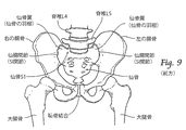
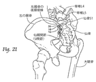
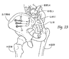
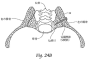
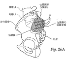
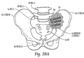
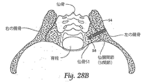
例えば、人間の腰帯(hip girdle)は3つの大きな骨から構成されていて、これらの骨は、相対的に不動の3つの関節によって連結されている(図9および10を参照)。これら3つの骨のうちの1つは仙骨と呼ばれ、腰椎の下端に位置しており、ここに脊椎L5が接続する。他の2つの骨は、一般には寛骨(hip bone)と呼ばれ、技術的には、右の腸骨および左の腸骨と呼ばれる。仙骨は、仙腸関節(SI関節)において、両方の寛骨に接続する。 For example, the human hip girdle is composed of three large bones that are connected by three relatively stationary joints (see FIGS. 9 and 10). One of these three bones is called the sacrum and is located at the lower end of the lumbar vertebra, to which the spine L5 is connected. The other two bones are commonly referred to as hip bones and are technically referred to as the right and left iliacs. The sacrum connects to both hipbones at the sacroiliac joint (SI joint).
SI関節は、背骨から低位の末端まで(あるいは、その逆方向に)力を伝達する機能を果たす。背中の下方部位の痛みは、その22%までがSI関節が原因であると説明されてきた。 The SI joint functions to transmit force from the spine to the lower end (or vice versa). Up to 22% of the pain in the lower part of the back has been described as being caused by the SI joint.
SI関節から生じる痛みを和らげるため、仙腸関節固定は、代表的な外科治療とされてきた。例えば、変性の仙腸関節炎(degenerative sacroiliitis)、炎症性の仙腸関節炎(inflammatory sacroiliitis)、医原性の仙腸関節の不安定(iatrogenic instability of the sacroiliac joint)、骨炎(osteitis condensans ilii)、あるいは骨盤の外傷性骨折変位(traumatic fracture dislocation of the pelvis)である。
現在、仙腸関節固定には、スクリュー、およびプレート付きスクリューが使用されている。同時に、SI関節の「滑膜関節」部分から、軟骨を取り除かなければならない。そのために大きな切り口を開ける必要がある。これは、損傷を受けた、亜脱臼した、変位した、骨折した、あるいは退位した関節にアプローチするためである。
Sacroiliac joint fixation has been considered a typical surgical treatment to relieve the pain arising from SI joints. For example, degenerative sacroiliitis, inflammatory sacroiliitis, iatrogenic instability of the sacroiliac joint, osteoitis condensans ilii, Or it is traumatic fracture dislocation of the pelvis.
Currently, screws and plate screws are used for sacroiliac joint fixation. At the same time, the cartilage must be removed from the “synovial joint” part of the SI joint. Therefore, it is necessary to open a large cut. This is to approach a damaged, subluxated, displaced, fractured or displaced joint.
本発明は、最小侵襲的な方法で隣接する骨セグメントを安定させるための、骨定着/固定システム、器具、およびそれに関連する方法を提供する。隣接する骨セグメントとは、骨折した1つの骨の複数の部分であってもよいし、あるいは隙間または関節によって隔てられた2以上の別々の骨であってもよい。
ここで使用する「隣接する骨セグメント(bone segments)」あるいは「隣接する骨領域」とは、次のいずれの状態をも意味している。例えば、1つの骨の骨折ライン(器具は定着のために用いられる)、あるいは、異なる骨領域間の隙間または関節(器具は、関節固定または固定のために用いられる)。したがって器具は、2またはそれ以上の骨を定着させる機能、1つの骨の2またはそれ以上の部分を固定する機能、あるいはその両方の機能を果たすことができる。
The present invention provides bone anchoring / fixation systems, instruments, and related methods for stabilizing adjacent bone segments in a minimally invasive manner. Adjacent bone segments may be multiple portions of a fractured bone, or two or more separate bones separated by a gap or joint.
As used herein, “adjacent bone segments” or “adjacent bone region” means any of the following states. For example, one bone fracture line (the instrument is used for anchoring), or a gap or joint between different bone regions (the instrument is used for joint fixation or fixation). Thus, the instrument can perform the function of anchoring two or more bones, the function of fixing two or more parts of a bone, or both.
本発明の1局面によれば、骨折ラインまたは関節によって隔てられた第1骨セグメントと第2骨セグメントを含む骨構造部を定着または固定するためのアセンブリ、およびそれに関連する方法が提供される。
本発明のアセンブリおよび関連する方法は、第1骨セグメントおよび第2骨セグメント内に導入できるよう、そのサイズおよび形状が定められたアンカー本体を含む。アンカー本体は、第2骨セグメントの内部領域に位置する末端部と、第1骨セグメントの外部領域に位置する基端部と、第1骨セグメントと第2骨セグメントの間の骨折ラインまたは関節を渡って延在する中間領域と、を備える。
本発明のアセンブリおよび関連する方法は末端側アンカーを含んでいて、当該末端側アンカーは、第2骨セグメントの内部領域に固定されていて、アンカー本体の上記末端部に連結されることで当該末端部を第2骨セグメント内に係止する。
本発明のアセンブリおよび関連する方法はさらに基端側アンカーを含んでいて、当該基端側アンカーは、第1骨セグメントの外部領域に固定されていて、アンカー本体の上記基端部に連結されることで、上記末端側アンカーと協働して、アンカー本体を圧縮状態に置き、第1骨セグメントおよび第2骨セグメントを骨折ラインまたは関節に沿って定着させる。
本発明のアセンブリおよび関連する方法はさらに細長いインプラント構造体を含んでいて、当該細長いインプラント構造体は、アンカー本体の上記中間領域に支持されて、第1骨セグメントと第2骨セグメントの間の骨折ラインまたは関節を渡って延在しており、当該インプラント構造体に沿って骨の内部成長または貫通成長を与えるよう処理された外表面領域を含んでいて、アンカー本体によって圧縮状態に保持されて定着されるべき第1骨セグメントおよび第2骨セグメントの定着または固定を促進する。
According to one aspect of the present invention, an assembly for fixing or securing a bone structure including a first bone segment and a second bone segment separated by a fracture line or joint and a method related thereto are provided.
The assembly and associated method of the present invention includes an anchor body that is sized and shaped for introduction into a first bone segment and a second bone segment. The anchor body includes a distal end located in the inner region of the second bone segment, a proximal end located in the outer region of the first bone segment, and a fracture line or joint between the first bone segment and the second bone segment. An intermediate region extending across.
The assembly and associated method of the present invention includes a distal anchor that is anchored to the interior region of the second bone segment and connected to the distal end of the anchor body for the distal end. The part is locked in the second bone segment.
The assembly and associated method of the present invention further includes a proximal anchor that is secured to the outer region of the first bone segment and connected to the proximal portion of the anchor body. Thus, in cooperation with the distal anchor, the anchor body is placed in a compressed state, and the first bone segment and the second bone segment are established along the fracture line or joint.
The assembly and associated method of the present invention further includes an elongated implant structure that is supported in the intermediate region of the anchor body to provide a fracture between the first bone segment and the second bone segment. Includes an outer surface region that extends across the line or joint and is treated to provide bone ingrowth or penetration growth along the implant structure and is held in compression and anchored by the anchor body Facilitates fixation or fixation of the first bone segment and the second bone segment to be performed.
本発明による骨定着/固定システム、器具、およびそれらに関連する方法は、SI関節において隣接する骨セグメント同士を安定させるのによく適している。 The bone anchoring / fixing system, instrument, and methods associated therewith according to the present invention are well suited for stabilizing adjacent bone segments in an SI joint.
従って、本発明の別の局面により、腸骨と仙骨の間の仙腸関節を固定するための方法が提供される。
本発明の方法は、腸骨、仙腸関節、および仙骨を通過して延在する挿通経路を形成する工程を含む。
本発明の方法は、上記挿通経路を通して横方向に腸骨および仙骨内に導入できるよう、サイズおよび形状が決められたアンカー本体を用意する工程を含む。当該アンカー本体は、仙骨の内部領域に位置するようそのサイズおよび形状が定められた末端部と、腸骨の外部領域に位置するようそのサイズおよび形状が定められた基端部と、仙腸関節を渡って延在するようそのサイズおよび形状が定められた中間領域と、を備える。
本発明の方法は、上記アンカー本体上に通されて腸骨と仙骨の間の仙腸関節を渡すことができるよう、そのサイズおよび形状が決められた細長いインプラント構造体を用意する工程を含む。当該細長いインプラント構造体は、当該インプラント構造体に沿って骨の内部成長または貫通成長を与えるよう処理された外表面領域を含んでいる。
本発明の方法は、上記挿通経路を通して、腸骨から、仙腸関節を通って、仙骨内へと、アンカー本体を導入する工程を含む。
本発明の方法は、アンカー本体の末端部を仙骨の内部領域に係止する工程を含む。
本発明の方法は、上記細長いインプラント構造体をアンカー本体上に通して、腸骨と仙骨の間の仙腸関節を渡す工程を含む。さらに、アンカー本体の基端部を腸骨の外部領域に係止して、上記係止された末端部との協働により、アンカー本体を圧縮状態に置くことで、仙腸関節を圧縮および定着させ、これにより、当該インプラント構造体における骨を内部成長または貫通成長させる領域が、アンカー本体によって圧縮保持され定着されるべき仙腸関節の定着または固定を促進する工程を含む。
Thus, according to another aspect of the invention, a method is provided for securing the sacroiliac joint between the iliac and sacrum.
The method of the present invention includes forming an insertion path extending through the iliac, sacroiliac joint, and sacrum.
The method of the present invention includes the step of providing an anchor body that is sized and shaped for introduction into the iliac and sacrum laterally through the insertion path. The anchor body has a distal end that is sized and shaped to be located in the inner area of the sacrum, a proximal end that is sized and shaped to be located in the outer area of the iliac, and the sacroiliac joint And an intermediate region that is sized and shaped to extend across.
The method of the invention includes providing an elongated implant structure sized and shaped to be passed over the anchor body to pass the sacroiliac joint between the iliac and sacrum. The elongate implant structure includes an outer surface region that is treated to provide bone ingrowth or penetration through the implant structure.
The method of the present invention includes the step of introducing the anchor body through the insertion path, from the iliac bone, through the sacroiliac joint, and into the sacrum.
The method of the present invention includes the step of locking the distal end of the anchor body to the internal region of the sacrum.
The method of the present invention includes passing the elongated implant structure over the anchor body and passing the sacroiliac joint between the iliac and sacrum. Furthermore, by locking the proximal end of the anchor body to the external region of the iliac and cooperating with the locked distal end, the anchor body is placed in a compressed state to compress and fix the sacroiliac joint And thereby promoting the anchorage or fixation of the sacroiliac joint where the bone ingrowth or penetration growth in the implant structure is to be compressed and held by the anchor body.
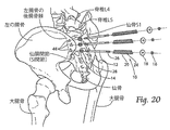
本発明の別の局面により、腸骨と仙骨の間の仙腸関節を固定するための方法であって、腸骨、仙腸関節、および仙骨を横方向に通過して延在する横方向挿通経路を形成することを含む方法が提供される。この方法は、骨定着インプラントを用意して、当該インプラントを、腸骨から、仙腸関節を通って、仙骨内へと横方向に、挿通経路内に導入する工程を含む。この方法は、骨定着インプラントを仙骨の内部領域に係止して、仙腸関節を定着させる工程を含む。 According to another aspect of the present invention, a method for securing a sacroiliac joint between an iliac and a sacrum, wherein the iliac, sacroiliac joint, and lateral insertion extending laterally through the sacrum A method is provided that includes forming a pathway. The method includes providing a bone anchoring implant and introducing the implant from the iliac bone, through the sacroiliac joint, laterally into the sacrum, and into the insertion path. The method includes locking the bone anchoring implant to an internal region of the sacrum to anchor the sacroiliac joint.
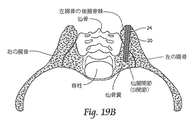
本発明の別の局面により、腸骨と仙骨の間の仙腸関節を固定するための方法であって、腸骨の後腸骨棘から入って、仙腸関節を通過して、仙骨翼で終わる後横方向挿通経路を形成することを含む方法が提供される。この方法は、骨定着インプラントを用意して、当該インプラントを、上記後横方向挿通経路内に導入する工程を含む。この方法は、骨定着インプラントを仙骨翼の内部領域に係止して、仙腸関節を定着させる工程を含む。 According to another aspect of the present invention, a method for fixing a sacroiliac joint between the iliac and sacrum, entering from the posterior iliac spine of the iliac, passing through the sacroiliac joint, and with a sacral wing A method is provided that includes forming a lateral insertion path after finishing. The method includes providing a bone anchoring implant and introducing the implant into the posterior transverse insertion path. The method includes locking the bone anchoring implant to an internal region of the sacral wing to anchor the sacroiliac joint.
一実施形態では、骨定着インプラントは、スクリューのような構造を含む。 In one embodiment, the bone anchoring implant includes a screw-like structure.
一実施形態では、骨定着インプラントは、固定ケージ構造を含む。 In one embodiment, the bone anchoring implant includes a fixed cage structure.
一実施形態では、骨定着インプラントは、細長いインプラント構造体を含む。このインプラント構造体は、直線で構成される断面形状を有しており、当該インプラント構造体に沿って、骨の内部成長または貫通成長を与えるよう処理された外表面領域を含んでいる。 In one embodiment, the bone anchoring implant includes an elongated implant structure. The implant structure has a cross-sectional shape comprised of straight lines and includes an outer surface region that is treated along the implant structure to provide bone ingrowth or penetration.
一実施形態では、挿通経路は、前もって軟骨を除去することなく、最少侵襲的な方法で形成される。 In one embodiment, the insertion path is formed in a minimally invasive manner without prior removal of the cartilage.
一実施形態では、挿通経路の内腔は、骨定着インプラントの最大外寸とほぼ同じか、ほぼそれに近い寸法とされる。 In one embodiment, the lumen of the insertion path is sized approximately the same as or close to the maximum outer dimension of the bone anchoring implant.
明細書中での開示は詳述で正確であるが、これは当業者が本発明を実施できるようにするためである。ここに開示した物理的な具体例は、単なる例示であって、他の具体的な構造をもって具体化されてもよいものである。好ましい具体例を説明しているが、その詳細は、請求項の記載で特定される本発明から逸脱することなく変更可能である。 The disclosure in the specification is precise in detail and is intended to enable those skilled in the art to practice the invention. The physical specific examples disclosed herein are merely examples, and may be embodied with other specific structures. While preferred embodiments have been described, the details can be changed without departing from the invention, which is specified in the claims.
I. 圧縮ステム・アセンブリ
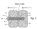
図1、2は、それぞれ組立図および分解図であって、圧縮ステム・アセンブリ10の代表的な形態を示している。このアセンブリ10のサイズおよび形状は、骨の断片の定着のために(すなわち、1つの骨の異なる部分を定着させるために)、あるいは固定されるべき各骨の定着のために(すなわち、隣接する、および(または)関節によって連結された2以上の各骨を定着させるために)、決定されている。
説明を簡便にするため、アセンブリ10を骨定着/固定圧縮アセンブリと呼ぶこともある。これは、当該アセンブリが、2またはそれ以上の各骨を定着させる機能も、また、1つの骨の2以上の部分を固定する機能も、あるいはその両方の機能も、いずれをも行ない得ることを示している。ここに使用されるように、「隣接する骨セグメント(bone segments)」あるいは「隣接する骨領域」とは、次のいずれの状態をも意味している。すなわち、1つの骨の骨折ライン、あるいは、異なる骨領域間の隙間または関節である。
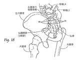
図1において、骨セグメントまたは隣接する骨領域は、図示を目的として、解剖学的詳細を伴わず概略的に示している。後の説明では(例えば、図13〜16、図20〜22において)、骨セグメントまたは隣接する骨領域は、骨盤の仙骨と腸骨の間の関を含む特定の解剖学的詳細と一緒に図示している。当該関節は、解剖学的には、仙腸関節(SI関節)と呼ばれる。
I. Compression Stem Assembly FIGS. 1 and 2 are an assembled view and an exploded view, respectively, showing a representative form of the
For ease of explanation, the
In FIG. 1, bone segments or adjacent bone regions are shown schematically without anatomical details for purposes of illustration. In a later description (eg, in FIGS. 13-16, 20-22), a bone segment or adjacent bone region is illustrated with specific anatomical details including the relationship between the pelvic sacrum and iliac bone. Show. The joint is anatomically called the sacroiliac joint (SI joint).
図1、2に示したように、圧縮ステム・アセンブリ10は、アンカー本体12を含む。アンカー本体12は、(図1に示したように)隣接する骨セグメントまたは骨領域内に、圧縮状態で配置できるように、そのサイズおよび形状が決められている。図示した具体例では、アンカー本体12は、円筒状のアンカー・ピン、あるいはロッドの形態を為している。しかしながら、アンカー本体12は、他の幾何形状を為していてもよい。
As shown in FIGS. 1 and 2, the
アンカー本体12の末端は、末端側アンカー・スクリュー14に係止される。このアンカー・スクリュー14は、上記隙間または関節の一側方において骨の内部領域に連結されている。当該隙間または関節の他の一側方においては、アンカー本体12の基端が、アンカー・ナット16およびアンカー・ワッシャ18を用いて、骨の外部領域に固定される。
末端側アンカー・スクリュー14とアンカー・ナット16によって、アンカー本体12は圧縮状で保持される。そして、そのようにされている限りは、アンカー本体12は、隣接する骨セグメントあるいは骨領域を圧縮し、定着させる。
The distal end of the
The
骨領域あるいはセグメントの内部において、アンカー本体12は、細長いステムのような、カニューレ状インプラント構造体20を保持する。インプラント構造体20は内腔部22を有していて、アンカー本体12上をスライドさせて配置することができる。図2に示すように、インプラント構造体20は、少なくともその長さの一部に渡って形成された領域24を含んでいる。この領域24は、当該構造体の表面上へ、または表面内部へと骨が成長することを促進する。あるいは、当該構造体の一部または全体に渡って骨が成長することを促進する。
インプラント構造体20の表面に沿って形成された、骨を内部成長(in-growth)または貫通成長(through-growth)させるための領域24は、インプラント構造体20の表面上に、またはその内部へ、あるいはこれを貫通して、骨が内部成長(in-growth)または貫通成長(through-growth)することを促進する。
インプラント構造体20の表面上に、またはその内部へ、あるいはこれを貫通して、骨が内部成長(in-growth)または貫通成長(through-growth)することは、アンカー本体12で圧縮保持されている骨セグメントあるいは骨領域の固定プロセスまたは骨折治癒時間を速めることを助ける。
Within the bone region or segment, the
A
In-growth or through-growth of bone on or into the surface of the
A. アンカー本体、ナット、およびワッシャ
アンカー本体12、ナット16およびワッシャ18は、人工補綴の分野において使用可能な材料から、例えば、機械加工、型成形、押出しによって作ることができる。使用可能な材料は、圧縮力が作用した状態で埋め込むことが可能であって、周囲の骨または組織に長時間さらされても、重大な生物学的吸収(bio-absorption)あるいは再吸収(resorption)が生じることのない材料である。アンカー本体12、ナット16、およびワッシャ18は、骨折した部位あるいは固定すべき部位を安定させるのに十分な一定時間の間、所定位置に留まることが意図されている。
そのような材料としては、それらに限定されるものではないが、チタン、チタン合金、タンタル、クロム・コバルト、医療用鋼材(surgical steel)、あるいは他の総合関節置換金属(total joint replacement metal)、および(または)セラミック、焼結ガラス、人工骨、何らかの非接合金属(uncemented metal)、またはセラミック表面、あるいはそれらの組み合わせを挙げることができる。
A. Anchor body, nut and washer The
Such materials include, but are not limited to, titanium, titanium alloys, tantalum, chromium cobalt, medical steel, or other total joint replacement metal, And / or ceramic, sintered glass, artificial bone, any uncemented metal, or ceramic surface, or combinations thereof.
長さに関しては(図1を参照)、アンカー本体12は、隣接する一方の骨セグメントあるいは領域から、その間の隙間または関節を超えて、隣接する他方の骨セグメントあるいは領域内に少なくとも部分的に入り込み得る長さにサイズ決めされている。アンカー本体12の長さおよび直径は、解剖部位に従ってサイズ決めされる。
局所構造の形態論は、医療専門家であれば、人間解剖学のテキストブックを使用し、かつその部位における疾患または外傷に関する知識に基づいて、一般的に理解できる。医師は、目的とする骨領域の形態論に関して以前に示された分析に基づき、例えば、単純なフィルムX線、透視検査用X線、MRI、あるいはCTスキャンを使用して、アンカー本体12の寸法を確認することができる。アンカー本体12用の代表的な直径は、3.2mm〜3.5mmである。
With respect to length (see FIG. 1), the
The morphology of the local structure can generally be understood by medical professionals using a human anatomy textbook and based on knowledge about the disease or trauma at the site. Based on the analysis previously shown with respect to the bone area morphology of interest, the physician can determine the dimensions of the
図2に最も良く示されているように、アンカー本体12の少なくとも基端領域および末端領域は、その筒状本体の回り形成された外部螺旋形畝あるいはスクリュー・ネジ26、28を含んでいる。望まれる場合には代わりの構成として、アンカー本体12の全長に沿ってネジを切ってもよい。望ましくは、スクリュー・ネジ26、28は、アンカー本体12の基端および末端において同方向に形成される。例えば、右方向ネジが望ましい。
As best shown in FIG. 2, at least the proximal and distal regions of the
ネジ26が形成されたアンカー本体12の基端部は、使用時に、隣接する1つの骨セグメントまたは領域の外側に一定距離だけ延在するよう、その寸法が決められる。このようにして、基端側領域は、使用時にアンカー・ナット16およびワッシャ18を取り付けることができるよう外部に露出する。アンカー・ナット16は相補的な内ネジを含んでいて、この内ネジは、アンカー本体12の基端側外面に形成された外ネジ26と係合するように、そのサイズおよび形状が決められている。
3.2mmのアンカー本体12に対しては、アンカー・ナット16およびアンカー・ワッシャ18の代表的な直径は、それぞれ、3.2mmおよび8mmである。
The proximal end of the
For a 3.2
ネジ28が形成されたアンカー本体12の末端部は、隣接する他方の骨セグメントあるいは領域内へと少なくとも部分的に入り込み得るように、そのサイズが決められている。そこでアンカー本体12の末端部は、アンカー・スクリュー14に連結されることとなるが、これについて次に説明する。
The distal end of the
B. アンカー・スクリュー
アンカー本体12、ナット16、およびワッシャ18と同様に、アンカー・スクリュー14は、人工補綴の分野において使用可能な耐久性材料から、例えば、機械加工、型成形によって作ることができる。使用可能な材料は、骨内にネジ込むことが可能であって、周囲の骨または組織に長時間さらされても、重大な生物学的吸収(bio-absorption)あるいは再吸収(resorption)が生じることのない材料である。
アンカー・スクリュー14は、圧縮アセンブリ10の他の構成要素と同様に、骨折した部位あるいは固定すべき部位を安定させるのに十分な一定時間の間、所定位置に留まることが意図されている。そのような材料としては、それらに限定されるものではないが、チタン、チタン合金、タンタル、クロム・コバルト、医療用鋼材(surgical steel)、あるいは他の総合関節置換金属(total joint replacement metal)、および(または)セラミック、あるいはそれらの組み合わせを挙げることができる。
B. Anchor Screw Similar to the
The
アンカー・スクリュー14は、隣接する他方の骨セグメントあるいは領域内において、アンカー本体12のネジ切りされた末端領域28の終端と係合し得る距離だけ延在するよう、そのサイズが決められている。図2に最も良く示されているように、アンカー・スクリュー14は、その筒状本体の回りに形成された外部螺旋形畝あるいはスクリュー・ネジ30を含んでいる。
外ネジ30は、骨内で回転した時にある目的を達成するために、そのサイズおよび形状が決められている。すなわち、アンカー・スクリュー14が、骨内にネジ込まれることによって前進配置される。骨内に配置されたアンカー・スクリュー14は、軸方向への移動および分離に対して抵抗する。アンカー・スクリュー14の代表的な長さ範囲は5mm〜20mmであるが、これも局所的解剖学見地からの要求によって変更され得る。アンカー・スクリュー14の代表的な直径は約7mmである。
The
The
アンカー・スクリュー14はさらに、その内腔に形成された内部螺旋形畝あるいはスクリュー・ネジ32を含んでいる。内側のスクリュー・ネジ32は、アンカー本体12の末端側に形成された相補的な外部スクリュー・ネジ28と係合するよう、そのサイズおよび形状が決められている。
アンカー・スクリュー14の内側スクリュー・ネジ32と係合したとき、アンカー・スクリュー14は、アンカー本体12の末端領域を骨に係止して、アンカー本体12が軸方向に移動するのを阻む。前に説明したように、アンカー・スクリュー14(末端領域上)、およびアンカー・ナット16とアンカー・ワッシャ18(基端領域上)が、アンカー本体12を圧縮状態で保持し、それによって、隣接する骨セグメントあるいは骨領域を圧縮・定着させる。
The
When engaged with the
別例として、アンカー・スクリュー14に代えて、内部にネジが切られた構成要素(外側にネジが無くてもよい)が、最も末端側の骨セグメントに形成した内腔の中にしっかりと固定できるように(例えば、締まり嵌めや、接着剤を利用する)、そのサイズおよび形状が決められてもよい。最も末端側の骨セグメントとは、上記内腔が終結している骨セグメントである。
アンカー・スクリュー14と同様に、締まり嵌めおよび(または)接着剤は、インプラント構造体の全体を係止する。アンカー・スクリュー14と組み合わせて接着剤を使用することも可能である。
As an alternative, instead of the
As with the
C. インプラント構造体
インプラント構造体20は、人工補綴の分野において使用可能な材料から、例えば、機械加工、型成形、押出しによって作ることができる。使用可能な材料は、周囲の骨または組織に長時間さらされても、重大な生物学的吸収(bio-absorption)あるいは再吸収(resorption)が生じることのない材料である。インプラント構造体20は、圧縮アセンブリ10の他の構成要素と同様に、骨折した部位あるいは固定すべき部位を安定させるのに十分な一定時間の間、所定位置に留まることが意図されている。
そのような材料としては、それらに限定されるものではないが、チタン、チタン合金、タンタル、チバニウム(アルミニウム、バナジウムおよびチタン)、クロム・コバルト、医療用鋼材(surgical steel)、あるいは他の総合関節置換金属(total joint replacement metal)、および(または)セラミック、焼結ガラス、人工骨、何らかの非接合金属(uncemented metal)、またはセラミック表面、あるいはそれらの組み合わせを挙げることができる。
別例として、インプラント構造体20は、適切な耐久性を有する生物学材料、または金属と生物学材料の組合せから形成されてもよい。例えば、生体適合性の骨充填材料である。インプラント構造体20は、例えばアクリル性の骨セメント等、流動性のある生物学的材料から型成形されてもよい。当該アクリル性の骨セメント等は、例えばUVライトによって硬化されて、流動性の無い固体材料となる。
C. Implant structure The
Such materials include, but are not limited to, titanium, titanium alloys, tantalum, cibanium (aluminum, vanadium and titanium), chrome cobalt, medical steel, or other general joints. There may be mentioned total joint replacement metal and / or ceramic, sintered glass, artificial bone, some uncemented metal, or ceramic surface, or combinations thereof.
As another example, the
インプラント構造体20は、解剖部位に従ってサイズ決めされる。局所構造の形態論は、医療専門家であれば、人間解剖学のテキストブックを使用し、かつその部位における疾患または外傷に関する知識に基づいて、一般的に理解できる。医師は、目的とする骨領域の形態論に関して以前に示された分析に基づき、例えば、単純なフィルムX線、透視検査用X線、MRI、あるいはCTスキャンを使用して、インプラント構造体20の寸法を確認することができる。
The
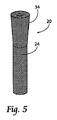
図3〜7に示すように、インプラント構造体20は、様々な外形および断面形状を有することができる。インプラント構造体20は、例えば、大略曲線(丸、楕円形)の断面を有していてもよいし(図3参照)、または全体的に直線で構成された断面(正方形、長方形、三角形)を有していてもよい(図4参照)し、あるいはそれらの組合せからなる断面を有していてもよい。
図2では、インプラント構造体20を断面三角形に描いているが、このような形状であれは、埋め込まれると、回転および微少変位を有効に防ぐことができる。
As shown in FIGS. 3-7, the
In FIG. 2, the
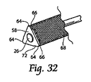
図5、6に示すように、インプラント構造体20は、曲線状(図5)か直線状(図6)である場合、その軸方向に沿う少なくとも一部分にテーパ領域34を含んでいてもよい。これは、インプラント構造体20の幅または直径が、軸方向に沿って徐々に増加するということを意味している。
望ましくは、テーパ領域34は、使用に際して、インプラント構造体20の基端領域(すなわち、インプラント構造体20の骨内に進入する最終部分)に対応する。幅または直径の増加割合は変更可能である。例えば、7mmの通常直径のインプラント構造体20の場合は、最大増加割合は、約0.25mmから1.25mmまでとすることができる。テーパ領域34が存在することで、隣接する骨セグメントまたは領域における圧縮力の生成および維持をさらに確実なものとなる。
As shown in FIGS. 5 and 6, when the
Desirably, the tapered
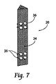
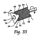
隣接する骨セグメントまたは領域における圧縮力の生成および維持をさらに確実なものとするため(図7参照)、インプラント構造体20は、曲線状、直線状、あるいはテーパ状のいずれの形態である場合にも、(歯、ウイング、その他の形態の)突出する骨グリップ面36を含むことができる。
歯またはウイング36は、インプラント構造体20の表面から例えば2〜4mm突出することができ、インプラント構造体20の基端および末端において圧縮力の方向に面を向ける。これにより、圧縮アセンブリによって圧縮されたときに、骨セグメント中に進入し易くなる。
In order to further ensure the generation and maintenance of compressive forces in adjacent bone segments or regions (see FIG. 7), the
The teeth or
図1、2で示したように、骨を内部成長(in-growth)または貫通成長(through-growth)させる領域24は、インプラント構造体20の全外表面に渡って延在している。あるいは、当該領域24は、隣接する骨セグメントの両側(または骨折ライン)において一定の距離部分だけをカバーしていてもよい。
骨を内部成長(in-growth)または貫通成長(through-growth)させる領域24は、例えば、貫通孔、および(または)多様な表面パターン、および(または)多様な表面性状、および(または)細孔、またはそれらの組合せを含んでいてもよい。当該領域24の形状は、変更することが勿論可能である。例示すると、当該領域24は、オープンメッシュ構造、ビード形状、小柱形状を含んでいてもよく、または、孔あるいは窓(fenestration)を含んでいてもよい。
骨を内部成長(in-growth)または貫通成長(through-growth)させるものであれば、どのような構造であって十分である。
As shown in FIGS. 1 and 2, a
Any structure that allows the bone to grow in-growth or through-growth is sufficient.
骨を内部成長(in-growth)または貫通成長(through-growth)させる領域24は、コーティング、ラッピング、または表面処理を施されることで、骨を内部成長または貫通成長させる。あるいは、当該領域24は、それ自体が本質的に骨の内部成長または貫通成長を促進する構造を有する材料から形成してもよい。例えば、多孔性メッシュ、ヒドロキシアパタイト、または他の多孔性表面である。領域24は、当該領域を貫通して骨が成長するための孔を含んでいてもよい。
The
好ましい具体例においては、骨を内部成長(in-growth)または貫通成長(through-growth)させる領域24は、インプラント構造体20上に、多孔性プラズマ・スプレー・コーティングを有する。これによって生体力学的に厳格な定着/固定システムが形成されるが、これは、信頼性の高い定着/固定、および大荷重耐性キャパシティーをサポートするよう設計されたものである。
In a preferred embodiment, the
骨を内部成長(in-growth)または貫通成長(through-growth)させる領域24は、他の多様なコーティングで覆われていてもよい。例えば、抗菌剤、抗血栓剤、骨形成誘発剤(osteoinductive agent)、あるいはそれらの組合せである。望まれる場合には、それらを用いてインプラント構造体20の全体をコーティングしてもよい。
The
D. 圧縮ステム・アセンブリのインプランテーション
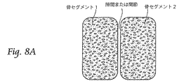
図8A〜8Lは、圧縮ステム・アセンブリ10をインプラントするための代表的な行程を、図解を目的として概略的に示している。より詳述には、圧縮ステム・アセンブリ10のSI関節への特定のインプラント技術について、解剖学的に重きを置いた説明を後述する。
D. Compression Stem Assembly Implantation FIGS. 8A-8L schematically illustrate, for purposes of illustration, a typical process for implanting
医師は、定着あるいは固定すべき(関節固定)隣接する骨セグメントあるいは骨領域を特定する(図8A)。
従来の可視化技術の助けを借りて、すなわち例えば、TVスクリーンに表示されるライブ映像を作り出す(Cアームまたはフルオロスコープ等の)X線画像インテンシファイヤを使用して、ガイド・ピン38が従来の手段によって導入される(図8B)。ガイド・ピン38は、隣接する1つの骨セグメントあるいは領域を貫通し、中間の隙間または関節を通過し、隣接する他方の骨セグメントあるいは領域内へと部分的に進入する。
The doctor identifies adjacent bone segments or bone regions to be anchored or fixed (joint fixation) (FIG. 8A).
With the help of conventional visualization techniques, i.e., using an X-ray image intensifier (such as a C-arm or fluoroscope) that produces live video displayed on a TV screen, for example, the
筒状のドリル・ビット40をガイド・ピン38上に通し(図8C)、案内挿入経路または内腔部42を形成する。この内腔部42は、隣接する1つの骨セグメントあるいは領域を貫通し、中間の隙間または関節を通過し、隣接する他方の骨セグメントあるいは領域内へと部分的に進入する。
単一のドリル・ビットまたは複数のドリル・ビット40を使用して、骨の断片または表面を貫通するようドリル加工し、所望のサイズおよび形状の案内内腔部42を形成する。案内内腔部42から末端側にある骨の部位は、ドリル加工せずにそのまま残され、そこにアンカー・スクリュー14が装着される。案内内腔部42が完成すれば、筒状のドリル・ビット40を取り外す。
A
A single drill bit or
インプラント構造体20の外形および寸法に適合する外形および寸法を有するブローチ44(図示した実施形態では三角形)を、ガイド・ピン38上でタップして、案内内腔部42に通す(図8D)。
当該形状のブローチ44が案内内腔部42のエッジに沿ってカッティングを行い、所望のプロファイルを作り出す(図示した実施形態では三角形)。当該プロファイルによって、インプラント構造体20は、隣接する1つの骨セグメントあるいは領域を貫通し、中間の隙間または関節を通過し、隣接する他方の骨セグメントあるいは領域内へと部分的に進入して、保持される。
A broach 44 (in the illustrated embodiment, a triangle) having an outline and dimensions that match the outline and dimensions of the
The shaped
ブローチ44を引き抜く(図8E)。そして、アンカー・スクリュー14(その内部スクリュー・ネジ32は、筒状ネジ・スクリュー・ドライバー46の末端部に係合している)を、ガイド・ピン38上に通し、さらに末端側の骨セグメント内のブローチ加工された内腔48の終端部にまで通す。アンカー・スクリュー14は、ブローチ加工された内腔48の終点を超えて、ドリル加工されずそのまま残された骨内に、スクリュー・ドライバー46を操作することによって、ネジ込まれる(図8F)。
例えば、アンカー・スクリュー14は、ブローチ加工された内腔48の終点を少なくとも5mm超えて、骨内に前進し、埋め込まれる。
The
For example, the
ネジ・スクリュー・ドライバー46は、逆回転させることによって、アンカー・スクリュー14から外される。そして、ガイド・ピン38が外される(図8G)。アンカー本体12が挿入され、そのネジ切りされた末端部28が、アンカー・スクリュー14の内側スクリュー・ネジ32とネジ係合する(図8H)。
The screw and screw
図8Hに示したように、その推奨されるサイズおよび形状により、ネジ切りされた末端部28がアンカー・スクリュー14と適切にネジ係合するとき、アンカー本体12のネジ切りされた基端部26は、ブローチ加工された内腔48の基端部外側に一定距離だけ突出する。
As shown in FIG. 8H, due to its recommended size and shape, the threaded
インプラント構造体20は、インプラント構造体20の末端側がアンカー・スクリュー14の基端側に当接するまでアンカー本体12上をスライドさせることで、当該アンカー本体12上に通される(図8I)。
The
アンカー・ワッシャ18は、突出しているアンカー本体12のネジ切りされた基端部26上をスライドさせて通され、骨の外表面に当接する(図8J)。アンカー本体12のネジ切りされた基端部26に、アンカー・ナット16をネジ係合させる(図8K)。所望の圧縮力がアセンブリ10によって骨領域に負荷されるまで、手動(または電動)チャック50を使用して、アンカー・ナット16をアンカー・ワッシャ18に対して締め付ける(図8L)。
圧縮により、隣接する骨セグメント間の距離が短くなり、同時に、インプラント構造体20は、ブローチ加工された内腔48内に圧縮状態で配置される。これにより、骨を内部成長させる領域24と、ブローチ加工された内腔内部の骨とが、密接に接触することが確実となる。
The
Compression reduces the distance between adjacent bone segments, while simultaneously placing the
骨を内部成長または貫通成長させる領域24において、インプラント構造体20の表面に沿って圧縮により作り出される密接な接触は、インプラント構造体20上への、同構造体内への、または同構造体内を貫通しての、内部成長または貫通成長を促進させ、したがって、固定行程または骨折治癒時間が短くなる。
In the
後により詳しく説明するように、ある1つの骨セグメントに対して、2以上の圧縮ステム・アセンブリ10をインプラントすることが可能である。例えば、後述するように(例えば、図20)、1つのSI関節を固定するために、そのような圧縮ステム・アセンブリを3つインプラントすることが可能である。
As will be described in more detail later, it is possible to implant more than one
E.他の実施形態
(1) 末端側のアンカープレート
圧縮ステム・アセンブリ10の別例を図31〜図33に示している。使用において、圧縮ステム・アセンブリ10は、既に説明したように、骨の定着または関節固定を目的として、隙間または関節によって隔てられた隣接する骨セグメントまたは領域内にインプラントできるように、そのサイズおよび形状が決められている。
E. Other Embodiments (1) Terminal Anchor Plate Another example of the
この実施形態(図31)では、アンカー本体12、ナット16、およびワッシャ18は、既に説明したのと同じようにして、そのサイズおよび形状が決められる。同様に、インプラント構造体20は、全体的に直線で構成される断面形状を有するように、そのサイズおよび形状が決められている。これも、図4を参照して既に説明した通りである。
In this embodiment (FIG. 31), the
この実施形態では、ネジが切られたアンカー・スクリュー14に代えて、全体的に直線で構成されたアンカープレート58によって、アセンブリ10の末端部が骨内に係止される。アンカープレート58は、人工補綴の分野において使用可能な硬質で耐久性のある材料から、例えば機械加工または型成形によって作ることができる。使用可能な材料は、骨の内部に切り込んで進入可能であって、周囲の骨または組織に長時間さらされても、重大な生物学的吸収(bio-absorption)あるいは再吸収(resorption)が生じることのない材料である。
In this embodiment, instead of the threaded
図31、32に最も良く示しているように、直線から構成されるアンカープレート58は、インプラント構造体自体の直線状の断面形状に適合するように、そのサイズおよび形状が決められている。
図示した構成においては、インプラント構造体20は、ほぼ三角形の断面形状を有しており、アンカープレート58もまたそのような形態を為している。そのため、アンカープレート58は、3つの頂点64を含んでいる。アンカープレート58の各頂点間の辺は、鋭く加工されていて、骨カッティングエッジ72を構成している。
As best shown in FIGS. 31 and 32, the
In the illustrated configuration, the
アンカープレート58は、その幾何学的中心位置に腔60を含んでいる(図31)。内部螺旋状畝あるいはネジ62が、腔60の内面に形成されている。この内部スクリュー・ネジ62は、アンカー本体12の末端領域に形成された相補的な外部スクリュー・ネジ28と適合するように、そのサイズおよび形状が決められている。
これによって、アンカー本体12の末端領域は、アンカープレート58とネジ係合できる(図32)。アンカー本体12にネジ係合されると、アンカープレート58は、アンカー本体12と共に回転する(図33)。
The
This allows the distal region of the
既に説明した方法によって(図8A〜図8D)ブローチ加工された内腔48内にインプラント構造体20を導入するに先立って、アンカー本体12は、インプラント構造体20の内腔22内に通され、そして、アンカー本体12の末端側のネジ切りされた部分28に、アンカープレート58がネジ係合される。ネジ切りされた部分28は、インプラント構造体20の末端部を越えて突出するように、そのサイズが決められている。
さらに、図32に示すように、アンカープレート58は、インプラント構造体20の末端部と整合するように回転方向の位置も決められている。この整合した位置においては(図32)、アンカープレート58の3つの頂点64は、インプラント構造体20の末端部の3つの頂点66と重なって、一致する。インプラント構造体20、アンカー本体12、およびアンカープレート58は、1つのユニットとして、ブローチ加工された内腔48内に、図32に示した姿勢で導入される。整合した位置では、アンカープレート58は、ブローチ加工された内腔48内にインプラント構造体20を通すことを妨げることはない。
Prior to introducing the
Further, as shown in FIG. 32, the
ブローチ加工された内腔の終点に接触すると、アンカー本体58の基端部を60°回転させる(図33)。この回転によって、アンカープレート58は、張り出た骨グリップ位置へと移動する。この位置では、アンカープレート58はもはや、インプラント構造体20の末端部とは整合していない(図33)。
この張り出た骨グリップ位置において、三角形のアンカープレート58の頂点64は、インプラント構造体20の三角形の辺68から半径方向外側に張り出している。アンカープレート58は、インプラント構造体20の末端部において、拡張された横方向面積を与える。この面積は、インプラント構造体自体の断面積よりも大きい。
When the end point of the broached lumen is contacted, the proximal end portion of the
In this protruding bone grip position, the apex 64 of the
アンカープレート58を骨グリップ位置へと回転させている間、アンカープレート58のカッティングエッジ72は、骨内部へと前進し、骨を切断する。これにより、アンカープレート58は、骨セグメントあるいは領域において、骨内部に据え付けられる(図34)。骨グリップ位置にあるアンカープレート58は、アンカー本体12の末端部を骨内に係止する。アンカープレート58は、アンカー・スクリュー14とほとんど同じ方法で、軸方向の移動および分離を防止する。
While rotating the
インプラント構造体20の辺68は、当該構造体20の末端部において、切欠き70を含んでいることが好ましい(図31、32)。アンカープレート58がその骨グリップ位置にまで回転したとき、アンカープレート58の本体が頂点間の戻り止めに隣接して、切欠き70内に位置することとなるように(図33)、切欠き70は、そのサイズおよび形状が決められている。
切欠き70内に位置したとき、アンカー本体12の基端部において、既に説明したようにしてアンカー・ナット16およびワッシャ18でさらに締め付けると、アンカープレート58は、骨をグリップする係止位置にロックされる。アンカー・ナットを締め付けることによって、インプラント構造体20は、末端側のアンカープレート58と基端側のナット/ワッシャの間で圧縮され(図34)、それにより、圧縮ステム・アセンブリ10を構成する。
The
When positioned within the
(2) 2ピースで構成される圧縮インプラント構造体
圧縮インプラント構造体の他の実施形態を図35A、35Bに示した。既に説明したように、使用に際して、インプラント構造体は、隙間または関節によって分離されている隣接する骨セグメントの内部に植設され、骨定着または関節固定を行うことを目的として、そのサイズおよび形状が決められる。
(2) Compression Implant Structure Consisting of Two Pieces Another embodiment of a compression implant structure is shown in FIGS. 35A and 35B. As already described, in use, the implant structure is implanted within adjacent bone segments separated by a gap or joint and is sized and shaped for the purpose of bone fixation or joint fixation. It is decided.
この実施形態(図35A)では、既に説明したのと同様に、インプラント構造体は、円または曲線で構成される断面形状を有することができる。既に説明したインプラント構造体とは異なり、図35Aに示したインプラント構造体20は、一緒に使用する2つのインプラント構成要素74、78からなる。
In this embodiment (FIG. 35A), as already described, the implant structure can have a cross-sectional shape comprised of a circle or a curve. Unlike the previously described implant structure, the
既に説明したのと同様に、インプラント構成要素74、78のそれぞれは、人工補綴の分野において使用可能な耐久性のある材料から、例えば、機械加工、型成形、押出しによって作ることができる。使用可能な材料は、周囲の骨または組織に長時間さらされても、重大な生物学的吸収(bio-absorption)あるいは再吸収(resorption)が生じることのない材料である。
インプラント構成要素74、78のそれぞれは、既に説明したのと同様に、骨を内部成長または貫通成長させる領域を外面に備えている。
As already described, each of the
Each of the
インプラント構造体を導入するに先立って、隣接する骨セグメントを貫通するように、ブローチ加工された内腔が、既に説明したのと同じやり方(図8A〜図8D)で形成される。インプラント構成要素74は、最も末端側の骨セグメントにブローチ加工された内腔の終端部にしっかりと固定できるように、そのサイズおよび形状が決められている。この固定は、例えば締まり嵌め、および(または)接着剤を使用して行われる。インプラント構成要素74によって、インプラント構造体の全体が係止される。
Prior to introducing the implant structure, a broached lumen is formed in the same manner as previously described (FIGS. 8A-8D) to penetrate adjacent bone segments. The
インプラント構成要素74は、さらにポスト76を含んでいる。このポストは、ブローチ加工された内腔を通って、ブローチ加工された内腔が始まる最も基端側の骨セグメント内にまで延在している。ポスト76は内ネジ80を含んでいる。
The
第2のインプラント構成要素78は、最も基端側の骨セグメントにブローチ加工された内腔内に導入され得るよう、そのサイズおよび形状が決められている。第2のインプラント構成要素78は内腔を含んでいて、その結果図35Bに示したように、当該インプラント構成要素78は、第1のインプラント構成要素74のポスト76上にスライドさせるようにして装着することができる。
The second implant component 78 is sized and shaped so that it can be introduced into a lumen broached into the most proximal bone segment. The second implant component 78 includes a lumen so that the implant component 78 is slid onto the
アンカー・スクリュー16(ワッシャ18と共に使用することが望ましい)は、外部スクリュー・ネジを含んでいる。この外部スクリュー・ネジは、ポスト76内に形成された相補的な内部スクリュー・ネジ80と係合し得るように、そのサイズおよび形状が決められている。アンカー・スクリュー16を締めると、第1および第2のインプラント構成要素74、78が互いに引き寄せられて、その結果、インプラント構造体が圧縮状態となる(図35B)。
Anchor screw 16 (preferably used with washer 18) includes an external screw screw. The external screw screw is sized and shaped to engage a complementary
(3) 半径方向圧縮
(スプリット・インプラント構造体)
他の実施形態であるインプラント構造体82を図36A、36Bに示した。既に説明したように、使用に際して、インプラント構造体82は、隙間または関節によって分離されている隣接する骨セグメントの内部に植設され、骨定着または関節固定を行うことを目的として、そのサイズおよび形状が決められる。
インプラント構造体82は、半径方向圧縮を行うべく配置されるよう、そのサイズおよび形状が決められている。
(3) Radial compression (split implant structure)
Another embodiment of an
The
既に説明したのと同様に、インプラント構造体82は、円または曲線で構成される断面形状を有する本体を含むことができる。既に説明したのと同様に、インプラント構造体82は、人工補綴の分野において使用可能な材料から、例えば、機械加工、型成形、押出しによって作ることができる。使用可能な材料は、周囲の骨または組織に長時間さらされても、重大な生物学的吸収(bio-absorption)あるいは再吸収(resorption)が生じることのない材料である。
インプラント構造体82は、既に説明したのと同様に、骨を内部成長または貫通成長させる領域を外面に1または2以上備えている。
Similar to that previously described, the
As already described, the
既に説明したインプラント構造体とは異なり、インプラント構造体82の基端部は、スプリット84を有する弱められた軸方向領域を含んでいる。セルフタッピング−スクリュー16がさらに含まれている。スクリュー16は、ネジが切られたテーパ状の本体を含んでいる。テーパ状本体は、スクリューヘッドに向かうにつれて直径が増加する楔型の形態を為している。
スクリュー16は、セルフタッピングタイプのものであって、スプリット84内にネジ込まれるとき、自身のためのネジ部を作り出しながら徐々に前進し得るように、そのサイズおよび形状が決められている(図36B)。
Unlike the previously described implant structure, the proximal end of the
The
インプラント構造体84を導入するに先立って、隣接する骨セグメントを貫通するように、ブローチ加工された内腔が、既に説明したのと同じやり方(図8A〜図8D)で形成される。図36Aに示したように、インプラント構造体84は、ブローチ加工された内腔内に導入される。
インプラント構成要素84は、最も末端側の骨セグメントにブローチ加工された内腔の終端部にしっかりと固定できるように、そのサイズおよび形状が決められている。この固定は、例えば締まり嵌め、および(または)接着剤を使用して行われる。締まり嵌め、および(または)接着剤によって、インプラント構造体84の全体が係止される。
Prior to introduction of the
The
ブローチ加工された内腔内にインプラント構造体84が導入された後、タッピンネジ16(ワッシャ18と共に使用することが望ましい)は、回転させられることによってスプリット84内へと徐々に前進する。図36Bに示したように、スクリュー16のネジ切りされた本体の楔形状によって、インプラント構造体84の本体は、スプリット84に沿って半径方向外側へと拡げられる。
スプリット84の回りでインプラント構造体82の本体の直径が拡がることにより、インプラント構造体82の基端部が隣接する骨に押し付けられる。スプリット84の回りでインプラント構造体82の本体が半径方向に拡張することで、インプラント構造体82の基端部が骨に押し付けられる。
このような半径方向への押し付けにより、ブローチ加工された内腔内において、骨の内部成長領域と骨とが確実に圧接し、同時に、骨セグメント内でのインプラント構造体82の回転および軸方向移動が防止される。
After the
As the diameter of the body of the
Such radial pressing ensures that the bone ingrowth region and the bone are in pressure contact within the broached lumen while simultaneously rotating and axially moving the
F. 圧縮を利用しないインプラント構造体
ここで説明した圧縮ステム・アセンブリ10を利用することなく、あるいは、インプラント構造体の圧縮を達成するための他の手段を利用することなく、骨折部位の定着させるために(つまり、同じ骨の異なる部分の定着)、または固定すべき骨を本体全体に渡って定着させるために(関節固定)、図2に示したような骨を内部成長および(または)貫通成長させる領域を有する細長いステム状のインプラント構造体20のサイズおよび形状が決められてもよい。
ここで説明ような圧縮ステム・アセンブリ10を利用することなく、骨折部位を定着させるために(つまり、同じ骨の異なる部分の定着)、または固定すべき骨を本体全体に渡って定着させるための、骨を内部成長および(または)貫通成長させる領域24を有する細長いステム状のインプラント構造体20が、例えば、2005年5月24日に出願された米国特許出願第11/136,141号において説明されている。当該内容は、言及することにより、本件明細書中に取り込まれる。
F. Implant structure that does not utilize compression To establish a fracture site without utilizing the
For anchoring a fracture site (ie, anchoring different parts of the same bone) or for anchoring the bone to be fixed throughout the body without using the
II. インプラント構造体を使用した仙腸関節の関節固定
図2(および他の別形態)に示したような細長いステム状のインプラント構造体20により、最小侵襲的な方法で、圧縮ステム・アセンブリ10を利用して、あるいはそれを利用することなく、SI関節(図9、10において、前方斜視図および後方斜視図を示している)の固定が可能となる。
これらのインプラント構造体20は、選択的に使用可能な2つの外科アプローチを使用して有効に植設することが可能である。すなわち、(i)横方向からのアプローチ、または(ii)後横方向からのアプローチである。いずれの手続においても従来の、横方向からの、および(または)後横方向からの可視化技術による支援を伴うことが望ましい。例えば、TVスクリーンに表示されるライブ映像を作り出す(Cアームまたはフルオロスコープ等の)X線画像インテンシファイヤによる支援である。
II. Arthrodesis of the sacroiliac joint using the implant structure The elongated stem-
These
A. 横方向からのアプローチ
(1) 圧縮ステム・アセンブリを使用しない場合
横方向からのアプローチの一実施形態においては(図11、12、13A/B)、1または2以上のインプラント構造体20が、腸骨からSI関節、そして仙骨S1内へと横方向に貫通するように導入される(その際、圧縮ステム・アセンブリ10は使用しない)。この経路およびインプラント構造体20の最終的な配置は、図12および図13A/Bに最も良く示されている。
図示した実施形態では、このような方法で3つのインプラント構造体20が配置されている。さらに、図示した実施形態では、インプラント構造体20は断面形状が三角形であるが、既に説明したような他の断面形状を有するインプラント構造体20を使用してもよい。
A. Lateral Approach (1) Without Compression Stem Assembly In one embodiment of the lateral approach (FIGS. 11, 12, 13A / B), one or
In the illustrated embodiment, three
横方向からのインプラント手続を試みる前に、医師は、定着または固定すべきSI関節セグメントを特定する(関節固定)。これには例えば、ファーバーテスト(Faber Test)、CTガイデド・インジェクション(CT-guided injection)、またはSI関節のX線/MRIを使用する。 Prior to attempting a lateral implant procedure, the physician identifies the SI joint segment to be established or fixed (joint fixation). For this, for example, Faber Test, CT-guided injection, or X-ray / MRI of SI joint is used.
横方向および前後方向(A-P)のCアームに支援されて、かつ、患者を(腹を下にして)うつ伏せにさせて、医師は、(横方向からの視覚化を使用して)大坐骨切痕(greater sciatic notch)の位置合わせをして、真の横位置を実現する。仙骨管の後方皮質と整合する位置からスタートし、それに続いて血液組織分離を行い、腸骨まで至る3cmの切り口を形成する。
横方向から見ると、腸骨上に配置されたガイド・ピン38(スリーブ付き)(例えば、シュタインマンピン)は、仙骨S1端部プレートより下方から始まって、仙骨管のちょうど前方位置にまで延在している。前後および横方向から見ると、ガイド・ピン38は、前方へ浅い角度で(図13Aに示すように、例えば、水平方向から15°〜20°)、S1端部プレートと平行となるべきである。
横方向から見ると、ガイド・ピン38は、仙骨前壁の後方に位置すべきである。前後方向に見ると、ガイド・ピン38は、下方のS1小孔よりも上方に位置するとともに、中央ラインの横方向に位置すべきである。このことは、図8A、図8Bに示したシーケンスにほぼ相当している。ガイド・ピン38を取り外す前に、軟組織プロテクタ(図示せず)をガイド・ピン38上にスライドさせて、腸骨に対してしっかりと押し付けることが望ましい。
Assisted by the lateral and anteroposterior (AP) C-arms and with the patient lying on its stomach (down on the stomach), the physician can make a sciatica (using lateral visualization) Aligns the great sciatic notch to achieve a true lateral position. Start from a position that matches the posterior cortex of the sacral canal, followed by blood tissue separation to form a 3 cm cut to the iliac.
Viewed laterally, a guide pin 38 (with a sleeve) (eg, a Steinman pin) placed on the iliac bone starts from below the sacral S1 end plate and extends to just anterior position of the sacral canal. Exist. When viewed from the front and back and from the side, the
When viewed from the side, the
ガイド・ピン38上を(かつ軟組織プロテクタを通して)、案内内腔42が、既に説明したようなやり方で、ドリル形成される(図8Cに概略的に示している)。案内内腔42は、腸骨を貫通して、SI関節を貫通して、そしてS1内へと延在する。ドリル刃先40が除去される。
Over the guide pin 38 (and through the soft tissue protector), the
ある形状のブローチ44が、ガイド・ピン38上を(かつ軟組織プロテクタを通して)案内内腔42内にネジ込まれて、ブローチ加工された内腔48を形成する。この内腔48は、インプラント構造体20に適したプロファイルを有する。プロファイルは、図示した形態においては三角形である。これは、図8Dに示したシーケンスにほぼ相当している。ブローチ加工された内腔48の三角形のプロファイルは図11に示している。
A shaped
図11、12に示したように(この実施形態では、圧縮スリーブ・アセンブリを使用せずに)、三角形のインプラント構造体20は、ガイド・ピン38上の軟組織プロテクタを通して、腸骨を通過して、SI関節を横切り、そしてS1へとたたき込むことができる。そして、インプラント構造体20の基端が腸骨の横壁に対して面一となる(図13A、13Bも参照)。
インプラント構造体20を腸骨の横壁と面一の状態(図13A、13B参照)でブローチ加工した経路内に残したまま、ガイド・ピン38および軟組織プロテクタを引き抜く。図示した実施形態では、さらに2つのインプラント構造体20がこのやり方で植設される(図12に最も良く示されている)。
As shown in FIGS. 11 and 12 (in this embodiment, without using a compression sleeve assembly), the
The
インプラント構造体20は、局所的解剖学に従ってそのサイズが決められる。SI関節に対しては、代表的なインプラント構造体20のサイズは、局所的解剖学によって、長さが約35mm〜約55mm、直径が約7mmである。
局所構造の形態論は、医療専門家であれば、人間解剖学のテキストブックを使用し、かつその部位における疾患または外傷に関する知識に基づいて、一般的に理解できる。医師は、目的とする骨領域の形態論に関して以前に示された分析に基づき、例えば、単純なフィルムX線、透視検査用X線、MRI、あるいはCTスキャンを使用して、インプラント構造体20の寸法を確認することができる。
The
The morphology of the local structure can generally be understood by medical professionals using a human anatomy textbook and based on knowledge about the disease or trauma at the site. Based on the analysis previously shown with respect to the bone area morphology of interest, the physician uses, for example, simple film X-rays, fluoroscopy X-rays, MRI, or CT scans of the
(2) 圧縮ステム・アセンブリを使用する場合
図14〜16A/Bに示したように、横方向からのアプローチにおいては、既に説明したような圧縮ステム・アセンブリ10を使用して、1または2以上のインプラント構造体20を、腸骨、SI関節、そして仙骨S1へと、横方向に貫通させて導入することもできる。その経路および最終的なインプラント構造体の配置は、図16A、16Bに最も良く示されている。
図11〜13A/Bに示した実施形態と同じようにして、3つのインプラント構造体が配置される。さらに、図11〜13A/Bに示した実施形態と同じようにインプラント構造体の断面形状は三角形であるが、既に説明したように、他の断面形状のものを使用してもよい。
横方向からアプローチするこの実施形態では、ブローチ加工された内腔48が形成された後直ちにインプラント構造体20が挿入されるのではない。そうではなく、圧縮ステム・アセンブリ10の構成要素が最初に内腔48内に設置されて、そこに、インプラント構造体20を受け入れる。
(2) When using a compression stem assembly As shown in FIGS. 14 to 16A / B, in the lateral approach, one or more of the
In the same manner as the embodiment shown in FIGS. 11-13A / B, three implant structures are arranged. Furthermore, the cross-sectional shape of the implant structure is a triangle as in the embodiment shown in FIGS. 11 to 13A / B, but other cross-sectional shapes may be used as described above.
In this embodiment approaching laterally, the
より詳しくは、ブローチ加工された内腔48を既に説明したように形成した後、軟組織プロテクタを所定位置に残したまま、ガイド・ピン38を外す。圧縮ステム・アセンブリ10のアンカー・スクリュー14は、仙骨S1内でブローチ加工された内腔48の終端を超えた位置に、図8G〜8Eに概略的に示した方法で配置される。
この構成では、圧縮ステム・アセンブリ10のアンカー・スクリュー14を配置するために、案内内腔42およびブローチ加工された内腔48の終点を越えた領域において、仙骨S1内の一定量の骨が、ドリル加工されずにそのまま残される。アンカー・スクリュー14は、仙骨S1内の当該ドリル加工されずに残された領域内へと前進して、図16A、16Bに示したように埋められる。そして、アンカー本体12のネジ切りされた末端部28と連結される。
More specifically, after forming the broached
In this configuration, in order to place the
既に説明し図8Hに示したように、アンカー本体12のネジ切りされた末端部28は、仙骨S1内のアンカー・スクリュー14とネジ係合する。このとき、アンカー本体12の他の部分は、基端側へ向かってSI関節および腸骨を貫通し、図16A、16Bに示すように、腸骨の横壁から一定距離だけ外側に突出する。
この後、既に説明し図8Iに示したように、インプラント構造体20は、アンカー本体12上をスライドさせて腸骨の横壁と面一の状態に設置される。そして、既に説明し図8J〜8Lに示したように、アンカー・ワッシャ18およびナットをアンカー本体12の基端部に取り付けて、締め付ける。これにより、アセンブリ10が圧縮状態となる。最終的な組立状態を、図15および16A/Bに示している。
As already described and shown in FIG. 8H, the threaded
Thereafter, as already described and shown in FIG. 8I, the
図14、15に示したように、3つの圧縮ステム・アセンブリ10は、横方向アプローチによって、SI関節を横切って設置することができる。アンカー・ナット16を締め付けることで各圧縮ステム・アセンブリが圧縮状態とされると、近隣する圧縮ステム・アセンブリのインプラント構造体が前進して、腸骨の横壁の向こう側へとわずかに突出し得る。これが生じた場合には、突き出たインプラント構造体20は、アンカー・ピン12上でさらに腸骨内へと、ゆっくりと叩き込むことができる。
As shown in FIGS. 14 and 15, the three
B. 後横方向からのアプローチ
(1) 圧縮ステム・アセンブリを使用しない場合
図17〜19A/Bに示したように、1または2以上のインプラント構造体は、(圧縮ステム・アセンブリ10を使用せずに)後横方向からのアプローチによって導入することができ、腸骨の後腸骨棘から入って、SI関節を通過して、仙骨翼まで延在する。この経路および最終的なインプラント構造体20の配置は、図18および19A/Bに最も良く示されている。
図示した実施形態では、このようなやり方で3つのインプラント構造体20が配置される。さらに、図示した実施形態では、インプラント構造体20の断面形状は三角形であるが、既に説明したように、他の断面形状であってもよい。
B. Rear Lateral Approach (1) Without Compression Stem Assembly As shown in FIGS. 17-19A / B, one or more implant structures can be used (without using
In the illustrated embodiment, three
後横方向からのアプローチにおいては、エントリー・ポイントである腸骨の後腸骨棘に存在する軟組織が少ないが故に、横方向からのアプローチの場合よりも軟組織の破壊が少ない。したがって、この部位からインプラント構造体20を導入すると、切り口をより小さく、より流動的なものとすることが可能となる。
さらに、インプラント構造体20は、後横方向からのルートに沿って、厳密な横方向ルートからの場合よりも多くの骨を通過する。そのため、SI関節のより多くの表面積がその部分に含まれることとなり、その結果、SI関節をより良好に定着または固定することができる。さらに、後横方向からのアプローチを採用すれば、L5神経根を含むすべての神経根を避けて通ることが可能となる。
In the posterior lateral approach, there is less soft tissue destruction than in the lateral approach because there is less soft tissue present in the posterior iliac spines of the iliac, which is the entry point. Therefore, when the
Furthermore, the
後横方向からのアプローチのためのセット・アップは、大略的には、横方向からのアプローチの場合と同じである。セット・アップには、定着または固定すべきSI関節セグメント(関節固定)を特定することが含まれており、例えば、ファーバーテスト(Faber Test)、CTガイデド・インジェクション(CT-guided injection)、またはSI関節のX線/MRIを使用して行う。これらは、患者が(腹を下にして)うつ伏せの状態で、かつ横方向Cアームおよび前後方向Cアームで援助されながら、行われるのが望ましい。
同じ器具を使用して、ガイド・ピン38上に案内内腔42が形成される。ただし、案内内腔42は、腸骨の後腸骨棘から始まって、SI関節を通過して、仙骨翼で終わる。案内内腔42は、既に説明したように(図17参照)、ブローチを使用して、所望のプロファイルを有する形状とされる。そして、インプラント構造体20が、図18および19A/Bに示した方法で、ブローチ加工された内腔48内に挿入される。
三角形のインプラント構造体20が、(この実施形態では、圧縮スリーブ・アセンブリ10を使用することなく)、ガイド・ピン38上を、軟組織プロテクタを通して、腸骨の後腸骨棘から、SI関節を通過して、仙骨翼で終わるところまで叩き込まれる。そのときインプラント構造体20の基端部は、図18に示したように、腸骨の後腸骨棘と面一になる。図17および図19A/Bに示したように、3つのインプラント構造体20が、このようなやり方で導入される。後ろからの横方向ルートに沿う骨の解剖学的形態論により、異なるサイズのインプラント構造体を導入することが推奨される(最も長いものと、それよりも短い他のもの)。
The setup for the rear lateral approach is generally the same as the lateral approach. Setup includes identifying the SI joint segment (joint fixation) to be fixed or fixed, eg, Faber Test, CT-guided injection, or SI Perform using X-ray / MRI of the joint. These are preferably done while the patient is lying prone (with the belly down) and assisted by the lateral and anteroposterior C-arms.
A
A triangular implant structure 20 (in this embodiment, without using the compression sleeve assembly 10) passes over the SI joint from the posterior iliac spine of the iliac, over the
(2) 圧縮ステム・アセンブリを使用する場合
図20〜22A/Bに示したように、後横方向からのアプローチにおいては、既に説明したような圧縮ステム・アセンブリ10を使用して、1または2以上のインプラント構造体20を、腸骨の後腸骨棘から入って、SI関節を通過して、仙骨翼内に進入するように導入することもできる。その経路および圧縮ステム・アセンブリ10を備えたインプラント構造体20の最終的な配置は、図22A/Bに最も良く示されている。
図17〜19A/Bに示した実施形態と同じようにして、3つのインプラント構造体が配置される。さらに、図17〜19A/Bに示した実施形態と同じようにインプラント構造体の断面形状は三角形であるが、既に説明したように、他の断面形状のものを使用してもよい。
後横方向からアプローチするこの実施形態では、ブローチ加工された内腔48が形成された後直ちにインプラント構造体20が挿入されるのではない。そうではなく、図20に示して既に説明したように、圧縮ステム・アセンブリ10の構成要素が最初に内腔48内に設置されて、そこに、インプラント構造体20を受け入れる。
(2) When using a compression stem assembly As shown in FIGS. 20 to 22A / B, in the rear lateral approach, the
Three implant structures are placed in the same manner as the embodiment shown in FIGS. Furthermore, although the cross-sectional shape of the implant structure is a triangle as in the embodiment shown in FIGS. 17 to 19A / B, other cross-sectional shapes may be used as described above.
In this embodiment approaching from the posterior lateral direction, the
既に説明したように、後横方向からのアプローチのためのセット・アップは、大略的には、横方向からのアプローチの場合と同じであって、患者が(腹を下にして)うつ伏せの状態で、かつ横方向Cアームおよび前後方向Cアームで援助されながら、行われるのが望ましい。同じ器具を使用して、ガイド・ピン38上に案内内腔42が形成される。案内内腔42は、腸骨の後腸骨棘から始まって、SI関節を通過して、仙骨翼で終わる。案内内腔42は、既に説明したように(図20参照)、ブローチを使用して、所望のプロファイルを有する形状とされる。
この構成では、圧縮ステム・アセンブリ10のアンカー・スクリュー14を配置するために、案内内腔42およびブローチ加工された内腔48の終点を越えた領域において、仙骨翼内の一定量の骨が、ドリル加工されずにそのまま残される。アンカー・スクリュー14は、仙骨翼内の当該ドリル加工されずに残された領域内へと前進して、図22A/Bに示したように埋められる。そして、アンカー本体12のネジ切りされた末端部28と連結される。
仙骨翼の形態論によれば、アンカー・スクリュー14は、横方向アプローチにおいて仙骨S1内に埋められる場合よりも短くてもよい。
As already explained, the setup for the posterior lateral approach is generally the same as for the lateral approach, with the patient lying down (with the belly down) And with the aid of the lateral C-arm and the longitudinal C-arm. A
In this configuration, in order to place the
According to the sacral wing morphology, the
既に説明し図8Hに示したように、アンカー本体12のネジ切りされた末端部28が、仙骨翼内のアンカー・スクリュー14とネジ係合する。そして、図21〜22A/Bに示したように、アンカー本体12の他の部分は、SI関節を貫通して基端側へと延在して、腸骨の上腸骨棘の外側に一定距離だけ突出する。
この後、既に説明し図8Iに示したように、インプラント構造体20は、アンカー本体12上をスライドさせて腸骨の上腸骨棘と面一の状態に設置される。そして、既に説明し図8J〜8Lに示したように、アンカー・ワッシャ18およびナットをアンカー本体12の基端部に取り付けて、締め付ける。これにより、アセンブリ10が圧縮状態となる。最終的な組立状態を、図21および22A/Bに示している。
As already described and shown in FIG. 8H, the threaded
Thereafter, as already described and shown in FIG. 8I, the
図20、21に示したように、3つの圧縮ステム・アセンブリ10は、後横方向アプローチによって、SI関節を横切って設置することができる。前に説明したように、アンカー・ナット16を締め付けることで各圧縮ステム・アセンブリが圧縮状態とされると、近隣する圧縮ステム・アセンブリ10のインプラント構造体20が前進して、腸骨の上腸骨棘の向こう側へとわずかに突出し得る。これが生じた場合には、突き出たインプラント構造体20は、アンカー本体12上でさらに上腸骨棘へと、ゆっくりと叩き込むことができる。
As shown in FIGS. 20 and 21, the three
C. 結論
後方からのアプローチ、あるいは後横方向からのアプローチのいずれかを使用すれば、既に説明したように、1または2以上のインプラント構造体20のそれぞれを、圧縮ステム・アセンブリ10を使用して、または使用せずに、あるいはその組み合わせによって、最少侵襲的な方法で、SI関節を横切るよう挿入することができる。
組織にアクセスする従来の器具、栓子、カニューレ、および(または)ドリルは、この目的に使用することができる。挿入経路を形成する前、あるいはインプラント構造体20の挿入前において、開先加工(joint preparation)、軟骨組織の除去、あるいはスクレーピングは必要ない。したがって、インプラント構造体20の最大外径と同じ、またはほぼそれに近いサイズで形成された最小侵襲的な挿入経路を形成する必要はある。
C. CONCLUSION If either the posterior approach or the posterior lateral approach is used, each of one or
Conventional instruments, obturators, cannulas, and / or drills that access tissue can be used for this purpose. There is no need for joint preparation, removal of cartilage tissue, or scraping before forming the insertion path or prior to insertion of the
圧縮ステム・アセンブリ10の使用を伴う、あるいは伴わないインプラント構造体20を使用することで、自己由来の骨移植材、追加的な茎状スクリューおよび(または)ロッド、中空のモジュラー固定スクリュー、カニューレ状の圧縮スクリュー、ジョイント内でネジが切られたケージ、あるいは骨折定着スクリューが不要となる。
By using the
代表的な処置では、患者の体格およびインプラント構造体20のサイズに応じて、1〜6個、あるいは多分8個のインプラント構造体20が必要となる。インプラント後、固定が行われる間、患者は、SI関節に負荷が作用するのを避けるよう助言されるであろう。その期間は、患者の健康状態および術後プロトコルの遵守度合いに依存し、6〜12週間またはそれ以上である。
A typical procedure will require 1-6, or perhaps eight,
インプラント構造体20を使用することで、従来の開腹手術の場合よりも侵襲性の少ない外科技術が可能となり、広範囲に渡る軟組織の除去は不要となる。SI関節に対して横方向からアプローチおよび後横方向からアプローチすることで、直線的な外科アプローチが提供され、これは、最小侵襲性の外科技術を補う。
インプラント構造体20のプロファイルおよびデザインは、回転および微少移動を最小限にする。チタンから作った硬質のインプラント構造体20を使用すれば、術後直ぐにSI関節が安定する。骨を内部成長させる領域24は、不規則な表面に多孔性のプラズ・マスプレー・コーティングが施されていて、安定した骨の定着/固定を支援する。インプラント構造体20および外科アプローチによって、術後の耐荷重キャパシティーが最大限となるよう設計された大きな固定表面積が実現され、かつ、大きな負荷がかかるSI関節を安定させるよう設計された、生物力学的に厳格なインプラントが提供される。
By using the
The profile and design of the
III. 他の構造体を使用した仙腸関節の関節固定
従来の横方向および(または)前後方向(A−P)での可視化技術の援助下で、SI関節に対して横方向からのアプローチおよび後横方向からのアプローチを行うことで、他の形態の定着/固定構造体を使用して、最小侵襲的な方法によるSI関節の定着が可能となる。
いずれのアプローチによっても、切り口のサイズが最少限となり、軟組織の除去が最小限となり、腱への刺激が最少限となり、痛みが少なく、感染症および合併症のリスクが少なく、失血が最小限となる。
III. Joint fixation of sacroiliac joints using other structures With lateral and / or anteroposterior (AP) visualization techniques, lateral approach and posterior lateral to SI joints By approaching from the direction, SI joints can be anchored in a minimally invasive manner using other forms of anchoring / fixing structures.
Either approach minimizes cut size, minimizes soft tissue removal, minimizes tendon irritation, reduces pain, reduces the risk of infection and complications, and minimizes blood loss. Become.
例えば(図23および図24A/Bを参照)、1または2以上のスクリュー状構造体52(例えば、中空のモジュラー係止スクリュー、カニューレ状の圧縮スクリュー、あるいは骨折定着スクリュー)を、本明細書で説明した横方向からのアプローチによって、腸骨を貫通し、SI関節を通過し、そして仙骨S1内へと横方向に導入することができる。この経路および最終的なスクリュー状構造体52の配置を、図23および図24A/Bに示している。
既に説明したように、スクリュー状構造体は、植設後に回転しないようにそのサイズおよび形状が決められているとともに、骨を内部成長させる材料、あるいは骨を貫通成長させる構造を備えていることが望ましい。
For example (see FIGS. 23 and 24A / B), one or more screw-like structures 52 (eg, hollow modular locking screws, cannulated compression screws, or fracture fixation screws) may be used herein. The described lateral approach can penetrate the iliac, pass through the SI joint, and be introduced laterally into the sacrum S1. This path and the final screw-
As already described, the size and shape of the screw-like structure are determined so as not to rotate after implantation, and the screw-like structure is provided with a material that allows bone to grow internally or a structure that allows bone to grow through. desirable.
同様に、1または2以上のスクリュー状構造体52は、本明細書で説明した後横方向からのアプローチによって、腸骨の後腸骨棘から入って、SI関節を通過して、仙骨翼で終わるよう、導入することができる。この経路および最終的なスクリュー状構造体52の配置を、図25および図26A/Bに示している。
既に説明したように、スクリュー状構造体52は、植設後に回転しないようにそのサイズおよび形状が決められているとともに、骨を内部成長させる材料、あるいは骨を貫通成長させる構造を備えていることが望ましい。
Similarly, one or more screw-
As already described, the size and shape of the screw-
別の例として、骨移植材料を含んでいる1または2以上の固定ケージ構造体54を、本明細書で説明した横方向からのアプローチによって、腸骨を貫通し、SI関節を通過し、そして仙骨S1内へと横方向に導入することができる。この経路および最終的な固定ケージ構造体54の配置を、図27および図28A/Bに示している。
そのような構造体54は、図27および図28A/Bに示しているように、仙骨S1内に植設されるアンカー・スクリュー要素56を含んでいてもよい。
As another example, one or more
Such a
同様に、1または2以上の固定ケージ構造体54は、本明細書で説明した後横方向からのアプローチによって、腸骨の後腸骨棘から入って、SI関節を通過して、仙骨翼で終わるよう、導入することができる。この経路および最終的な固定ケージ構造体54の配置を、図29および図30A/Bに示している。
そのような構造体54は、図27および図28A/Bに示しているように、仙骨翼内に植設されるアンカー・スクリュー要素56を含んでいてもよい。
Similarly, one or more
Such a
IV. 結論
以上の説明は、本発明の原理を図示することを目的としたものに過ぎないと、理解されるべきである。さらに、この分野における当業者にとっては、多数の修正および変更が容易であるが故に、ここに図示し説明した構造および操作そのままのものとして本発明が限定されるのは望ましくない。好ましい具体例について説明してきたが、その詳細は、特許請求の範囲で特定される本発明から逸脱することなく、変更することが可能である。
IV. Conclusion It should be understood that the foregoing description is only intended to illustrate the principles of the invention. Further, since many modifications and changes will be apparent to those skilled in the art, it is not desirable to limit the invention to the exact construction and operation shown and described herein. While preferred embodiments have been described, the details can be changed without departing from the invention as defined in the claims.
Claims (22)
アンカー本体は、第1骨セグメントおよび第2骨セグメント内に導入できるよう、そのサイズおよび形状が定められていて、第2骨セグメントの内部領域に位置する末端部と、第1骨セグメントの外部領域に位置する基端部と、第1骨セグメントと第2骨セグメントの間の骨折ラインまたは関節を渡って延在する中間領域と、を備える。
末端側アンカーは、第2骨セグメントの内部領域に固定されていて、アンカー本体の上記末端部に連結されることで当該末端部を第2骨セグメント内に係止する。
基端側アンカーは、第1骨セグメントの外部領域に固定されていて、アンカー本体の上記基端部に連結されることで、上記末端側アンカーと協働して、アンカー本体を圧縮状態に置き、第1骨セグメントおよび第2骨セグメントを骨折ラインまたは関節に沿って定着させる。
細長いインプラント構造体は、アンカー本体の上記中間領域に支持されて、第1骨セグメントと第2骨セグメントの間の骨折ラインまたは関節を渡って延在しており、当該インプラント構造体に沿って骨の内部成長または貫通成長を与えるよう処理された外表面領域を含んでいて、アンカー本体によって圧縮状態に保持されて定着されるべき第1骨セグメントおよび第2骨セグメントの定着または固定を促進する。
上記基端側アンカーは、末端側アンカーと協働して、インプラント構造体を圧縮状態に置き、それによって、骨の内部成長または貫通成長を与える領域を第1骨セグメントおよび第2骨セグメント内の骨に密接させる。
An assembly for anchoring or securing a bone structure including a first bone segment and a second bone segment separated by a fracture line or joint, comprising: an anchor body, a distal anchor, a proximal anchor, and an elongated An assembly comprising an implant structure.
The anchor body is sized and shaped to be introduced into the first bone segment and the second bone segment, a distal end located in the internal region of the second bone segment, and an external region of the first bone segment And an intermediate region extending across the fracture line or joint between the first bone segment and the second bone segment.
The distal anchor is fixed to the inner region of the second bone segment and is connected to the distal end of the anchor body to lock the distal end in the second bone segment.
The proximal anchor is fixed to the outer region of the first bone segment and is connected to the proximal end of the anchor body so that the anchor body is placed in a compressed state in cooperation with the distal anchor. The first and second bone segments are established along the fracture line or joint.
An elongated implant structure is supported in the intermediate region of the anchor body and extends across the fracture line or joint between the first bone segment and the second bone segment, and the bone structure along the implant structure. Including an outer surface region that is treated to provide ingrowth or penetration growth of the first and second bone segments that are to be held in compression by the anchor body and to be anchored.
The proximal anchor cooperates with the distal anchor to place the implant structure in a compressed state, thereby providing a region in the first and second bone segments that provides bone ingrowth or penetration. Close to bone.
The assembly of claim 1, wherein the distal anchor comprises an external thread.
The assembly of claim 2, wherein the anchor body is threaded at a distal end, and the threaded portion engages a screw formed in a screw lumen.
The assembly of claim 1, wherein the distal anchor includes an interference fit between the distal end of the anchor body and the bone in the interior region of the second bone segment.
The assembly of claim 1, wherein the distal anchor includes an adhesive applied between the distal end of the anchor body and the bone in the interior region of the second bone segment.
The assembly of claim 1, wherein the distal anchor includes a plate having a bone cutting edge that rotates into the bone.
The assembly of claim 1, wherein the distal anchor includes a triangular plate having a vertex and a bone cutting edge that rotates to bite into the bone.
The assembly of claim 1, wherein the distal anchor includes a plate that is rotatable to a bone grip position as the distal end of the anchor body rotates.
プレート領域は、骨グリップ位置にあるときに切欠き内に位置する、請求項8記載のアセンブリ。
The implant structure includes an end region having a notch adjacent to the plate,
9. The assembly of claim 8, wherein the plate region is located in the notch when in the bone grip position.
The assembly of claim 1, wherein the proximal anchor includes a nut.
The assembly of claim 10, wherein the proximal anchor further comprises a washer between the nut and the outer surface of the first bone segment.
The assembly of claim 10, wherein the anchor body is threaded at a proximal end and the threaded portion engages a screw formed in the lumen of the nut.
The assembly of claim 12, wherein the proximal anchor includes a washer between the nut and the outer surface of the first bone segment.
The assembly of claim 1, wherein the implant structure has a cross-sectional shape entirely surrounded by a curve.
The assembly of claim 1, wherein the implant structure has a cross-sectional shape entirely surrounded by a straight line.
The assembly of claim 1, wherein the implant structure has a generally triangular cross-sectional shape.
The assembly of claim 1, wherein the implant structure includes a tapered region.
The assembly of claim 1, wherein the implant structure includes a tapered region proximally.
The assembly of claim 1, wherein the cross-sectional shape of the implant structure is larger as it is closer to the proximal anchor than to the distal anchor.
The assembly of claim 1, wherein the implant structure includes a bone gripping surface on the outside.
The assembly of claim 1, wherein the region providing bone ingrowth or penetration in the implant structure comprises a porous plasma maspray coating.
Applications Claiming Priority (6)
| Application Number | Priority Date | Filing Date | Title |
|---|---|---|---|
| US10/914,629 US20060036251A1 (en) | 2004-08-09 | 2004-08-09 | Systems and methods for the fixation or fusion of bone |
| US12/924,784 US8388667B2 (en) | 2004-08-09 | 2010-10-05 | Systems and methods for the fixation or fusion of bone using compressive implants |
| US12/924,782 US8986348B2 (en) | 2004-08-09 | 2010-10-05 | Systems and methods for the fusion of the sacral-iliac joint |
| US12/924,782 | 2010-10-05 | ||
| US12/924,784 | 2010-10-05 | ||
| PCT/US2011/054935 WO2012048008A1 (en) | 2004-08-09 | 2011-10-05 | Systems and methods for the fixation or fusion of bone using compressive implants |
Related Child Applications (1)
| Application Number | Title | Priority Date | Filing Date |
|---|---|---|---|
| JP2015111540A Division JP2015211849A (en) | 2004-08-09 | 2015-06-01 | System and method for fixation or fusion of bone using compressive implants |
Publications (3)
| Publication Number | Publication Date |
|---|---|
| JP2013542775A JP2013542775A (en) | 2013-11-28 |
| JP2013542775A5 JP2013542775A5 (en) | 2014-06-05 |
| JP5771277B2 true JP5771277B2 (en) | 2015-08-26 |
Family
ID=57354022
Family Applications (2)
| Application Number | Title | Priority Date | Filing Date |
|---|---|---|---|
| JP2013532916A Active JP5771277B2 (en) | 2004-08-09 | 2011-10-05 | System and method for fixation or fixation of compression implants using bone |
| JP2015111540A Pending JP2015211849A (en) | 2004-08-09 | 2015-06-01 | System and method for fixation or fusion of bone using compressive implants |
Family Applications After (1)
| Application Number | Title | Priority Date | Filing Date |
|---|---|---|---|
| JP2015111540A Pending JP2015211849A (en) | 2004-08-09 | 2015-06-01 | System and method for fixation or fusion of bone using compressive implants |
Country Status (6)
| Country | Link |
|---|---|
| US (6) | US8388667B2 (en) |
| EP (1) | EP2624772B1 (en) |
| JP (2) | JP5771277B2 (en) |
| CN (1) | CN103237514B (en) |
| BR (1) | BR112013008227A2 (en) |
| WO (1) | WO2012048008A1 (en) |
Families Citing this family (192)
| Publication number | Priority date | Publication date | Assignee | Title |
|---|---|---|---|---|
| US7955357B2 (en) | 2004-07-02 | 2011-06-07 | Ellipse Technologies, Inc. | Expandable rod system to treat scoliosis and method of using the same |
| US9662158B2 (en) * | 2004-08-09 | 2017-05-30 | Si-Bone Inc. | Systems and methods for the fixation or fusion of bone at or near a sacroiliac joint |
| US8444693B2 (en) * | 2004-08-09 | 2013-05-21 | Si-Bone Inc. | Apparatus, systems, and methods for achieving lumbar facet fusion |
| US20180228621A1 (en) | 2004-08-09 | 2018-08-16 | Mark A. Reiley | Apparatus, systems, and methods for the fixation or fusion of bone |
| US8388667B2 (en) | 2004-08-09 | 2013-03-05 | Si-Bone, Inc. | Systems and methods for the fixation or fusion of bone using compressive implants |
| US20070156241A1 (en) * | 2004-08-09 | 2007-07-05 | Reiley Mark A | Systems and methods for the fixation or fusion of bone |
| US9949843B2 (en) | 2004-08-09 | 2018-04-24 | Si-Bone Inc. | Apparatus, systems, and methods for the fixation or fusion of bone |
| US20060036251A1 (en) | 2004-08-09 | 2006-02-16 | Reiley Mark A | Systems and methods for the fixation or fusion of bone |
| US8425570B2 (en) | 2004-08-09 | 2013-04-23 | Si-Bone Inc. | Apparatus, systems, and methods for achieving anterior lumbar interbody fusion |
| US8470004B2 (en) | 2004-08-09 | 2013-06-25 | Si-Bone Inc. | Apparatus, systems, and methods for stabilizing a spondylolisthesis |
| US8414648B2 (en) * | 2004-08-09 | 2013-04-09 | Si-Bone Inc. | Apparatus, systems, and methods for achieving trans-iliac lumbar fusion |
| WO2006034436A2 (en) | 2004-09-21 | 2006-03-30 | Stout Medical Group, L.P. | Expandable support device and method of use |
| FR2884406B1 (en) | 2005-04-14 | 2008-10-17 | Memometal Technologies Soc Par | INTRAMEDULAR OSTEOSYNTHESIS DEVICE OF TWO BONE PARTS, IN PARTICULAR HAND AND / OR FOOT |
| DE102005053819A1 (en) * | 2005-11-11 | 2007-05-16 | Khd Humboldt Wedag Gmbh | Rotary kiln burner |
| US8728387B2 (en) | 2005-12-06 | 2014-05-20 | Howmedica Osteonics Corp. | Laser-produced porous surface |
| JP5542273B2 (en) | 2006-05-01 | 2014-07-09 | スタウト メディカル グループ,エル.ピー. | Expandable support device and method of use |
| US7862502B2 (en) | 2006-10-20 | 2011-01-04 | Ellipse Technologies, Inc. | Method and apparatus for adjusting a gastrointestinal restriction device |
| US11202707B2 (en) | 2008-03-25 | 2021-12-21 | Nuvasive Specialized Orthopedics, Inc. | Adjustable implant system |
| FR2935601B1 (en) | 2008-09-09 | 2010-10-01 | Memometal Technologies | INTRAMEDULLARY IMPLANT RESORBABLE BETWEEN TWO BONE OR TWO BONE FRAGMENTS |
| US8382756B2 (en) | 2008-11-10 | 2013-02-26 | Ellipse Technologies, Inc. | External adjustment device for distraction device |
| US20100211176A1 (en) | 2008-11-12 | 2010-08-19 | Stout Medical Group, L.P. | Fixation device and method |
| US20100204795A1 (en) | 2008-11-12 | 2010-08-12 | Stout Medical Group, L.P. | Fixation device and method |
| US10779958B2 (en) * | 2014-12-22 | 2020-09-22 | Beacon Biomedical, Llc | Sacroiliac joint fusion systems and methods |
| US8821555B2 (en) | 2009-02-11 | 2014-09-02 | Howmedica Osteonics Corp. | Intervertebral implant with integrated fixation |
| US9241798B2 (en) * | 2009-03-20 | 2016-01-26 | David A. Petersen | Surgical methods and tools |
| US9622792B2 (en) | 2009-04-29 | 2017-04-18 | Nuvasive Specialized Orthopedics, Inc. | Interspinous process device and method |
| US9078701B2 (en) * | 2009-11-09 | 2015-07-14 | Centinel Spine, Inc. | System and method for stabilizing a posterior fusion over motion segments |
| US8348950B2 (en) * | 2010-01-04 | 2013-01-08 | Zyga Technology, Inc. | Sacroiliac fusion system |
| BR112012017259A2 (en) | 2010-01-13 | 2016-08-23 | Jcbd Llc | sacroiliac joint fusion and fixation system |
| US9421109B2 (en) * | 2010-01-13 | 2016-08-23 | Jcbd, Llc | Systems and methods of fusing a sacroiliac joint |
| WO2014015309A1 (en) | 2012-07-20 | 2014-01-23 | Jcbd, Llc | Orthopedic anchoring system and methods |
| US9381045B2 (en) | 2010-01-13 | 2016-07-05 | Jcbd, Llc | Sacroiliac joint implant and sacroiliac joint instrument for fusing a sacroiliac joint |
| US9333090B2 (en) | 2010-01-13 | 2016-05-10 | Jcbd, Llc | Systems for and methods of fusing a sacroiliac joint |
| WO2012174485A1 (en) | 2011-06-17 | 2012-12-20 | Jcbd, Llc | Sacroiliac joint implant system |
| CA2793185C (en) | 2010-03-16 | 2019-02-12 | Pinnacle Spine Group, Llc | Intervertebral implants and graft delivery systems and methods |
| US8900251B2 (en) | 2010-05-28 | 2014-12-02 | Zyga Technology, Inc | Radial deployment surgical tool |
| US9248043B2 (en) | 2010-06-30 | 2016-02-02 | Ellipse Technologies, Inc. | External adjustment device for distraction device |
| WO2012015976A1 (en) * | 2010-07-27 | 2012-02-02 | Ginn Richard S | System for sacro-iliac stabilization |
| EP2608747A4 (en) | 2010-08-24 | 2015-02-11 | Flexmedex Llc | Support device and method for use |
| US9149286B1 (en) | 2010-11-12 | 2015-10-06 | Flexmedex, LLC | Guidance tool and method for use |
| US9138219B2 (en) * | 2010-12-29 | 2015-09-22 | Tarsus Medical Inc. | Methods and devices for treating a syndesmosis injury |
| WO2012112396A2 (en) | 2011-02-14 | 2012-08-23 | Ellipse Technologies, Inc. | Device and method for treating fractured bones |
| US9687278B2 (en) * | 2011-03-21 | 2017-06-27 | Ronald Childs | Sleeve for bone fixation device |
| JP2014519369A (en) | 2011-05-05 | 2014-08-14 | ザイガ テクノロジー インコーポレイテッド | Sacroiliac fusion system |
| US8900279B2 (en) | 2011-06-09 | 2014-12-02 | Zyga Technology, Inc. | Bone screw |
| US8998925B2 (en) | 2011-06-20 | 2015-04-07 | Rdc Holdings, Llc | Fixation system for orthopedic devices |
| WO2012177759A1 (en) | 2011-06-20 | 2012-12-27 | Rdc Holdings, Llc | System and method for repairing joints |
| EP2726002B1 (en) | 2011-06-28 | 2019-04-17 | Spinologics Inc. | Bone screw fixation system |
| US20130018427A1 (en) * | 2011-07-15 | 2013-01-17 | Khiem Pham | Screw Implants For Bone Fusion |
| US10335216B2 (en) | 2011-07-15 | 2019-07-02 | Globus Medical, Inc. | Screw implants for bone fusion |
| US10925653B2 (en) | 2011-07-15 | 2021-02-23 | Globus Medical, Inc. | Screw implants for bone fusion |
| FR2978343B1 (en) * | 2011-07-25 | 2013-08-23 | Medicrea International | ANCHORING BODY FOR VERTEBRAL OSTEOSYNTHESIS EQUIPMENT |
| JP2014529445A (en) | 2011-08-23 | 2014-11-13 | フレックスメデックス,エルエルシー | Tissue removal apparatus and method |
| US9113972B2 (en) | 2011-08-24 | 2015-08-25 | Pioneer Surgical Technology, Inc. | Apparatus and methods for immobilization and fusion of a synovial joint |
| JP2015500667A (en) * | 2011-09-21 | 2015-01-08 | フレックスメデックス,エルエルシー | Support apparatus and method |
| US10743794B2 (en) | 2011-10-04 | 2020-08-18 | Nuvasive Specialized Orthopedics, Inc. | Devices and methods for non-invasive implant length sensing |
| US9820788B2 (en) | 2011-10-05 | 2017-11-21 | H. Lee Moffitt Cancer Center And Research Institute, Inc. | Bone fusion system |
| US10799367B2 (en) | 2011-10-05 | 2020-10-13 | H. Lee Moffitt Cancer Center And Research Institute, Inc. | Bone fusion system |
| US9615856B2 (en) * | 2011-11-01 | 2017-04-11 | Imds Llc | Sacroiliac fusion cage |
| WO2013066946A1 (en) | 2011-11-01 | 2013-05-10 | Ellipse Technologies, Inc. | Adjustable magnetic devices and methods of using same |
| US9380932B1 (en) | 2011-11-02 | 2016-07-05 | Pinnacle Spine Group, Llc | Retractor devices for minimally invasive access to the spine |
| US20130158610A1 (en) * | 2011-12-16 | 2013-06-20 | Depuy Mitek, Inc. | Bone graft fixation systems and methods |
| EP2809252A4 (en) | 2012-01-31 | 2016-02-17 | Univ Toledo | Bioactive fusion device |
| US20130245703A1 (en) * | 2012-03-02 | 2013-09-19 | Interventional Spine, Inc. | Method and apparatus for sacroiliac joint fixation |
| CN104334102A (en) | 2012-03-09 | 2015-02-04 | 西-博恩公司 | Integrated implant |
| WO2013134682A1 (en) | 2012-03-09 | 2013-09-12 | Si-Bone Inc. | Artificial si joint |
| US20140276846A1 (en) * | 2013-03-15 | 2014-09-18 | Richard G. Mauldin | Systems and methods for implanting bone graft and implant |
| JP2015509435A (en) * | 2012-03-09 | 2015-03-30 | エスアイ−ボーン・インコーポレイテッドSi−Bone, Inc. | Threaded implant |
| US10363140B2 (en) | 2012-03-09 | 2019-07-30 | Si-Bone Inc. | Systems, device, and methods for joint fusion |
| CN104334092A (en) * | 2012-05-04 | 2015-02-04 | 西-博恩公司 | Fenestrated implant |
| US20140012340A1 (en) * | 2012-07-05 | 2014-01-09 | Warsaw Orthopedic, Inc. | Sacro-iliac joint implant system and method |
| CN103536348A (en) * | 2012-07-10 | 2014-01-29 | 北京爱康宜诚医疗器材股份有限公司 | Integration anchoring bone nail |
| US20140031934A1 (en) * | 2012-07-26 | 2014-01-30 | Warsaw Orthopedic, Inc. | Sacro-iliac joint implant system and method |
| US9295488B2 (en) * | 2012-08-09 | 2016-03-29 | Wilson T. Asfora | Joint fusion |
| US20140067069A1 (en) | 2012-08-30 | 2014-03-06 | Interventional Spine, Inc. | Artificial disc |
| DE202012103384U1 (en) | 2012-09-05 | 2012-09-24 | Signus Medizintechnik Gmbh | Pelvic ring implant |
| CN104902854B (en) | 2012-10-29 | 2017-10-03 | 诺威适骨科专科公司 | The adjustable apparatus scorching for treating knee endoprosthesis |
| WO2014078321A1 (en) * | 2012-11-13 | 2014-05-22 | Greenberg Louis E | Orthopedic implant having non-circular cross section and method of use thereof |
| US20140188179A1 (en) * | 2012-12-27 | 2014-07-03 | Wright Medical Technology, Inc. | Percutaneous flaring hammertoe fixation implant and instrument |
| AU2013373795B2 (en) * | 2013-01-15 | 2017-03-30 | Friedrich Müller | MTV implantation set |
| US9186155B2 (en) * | 2013-03-14 | 2015-11-17 | NuTech Spine, Inc. | Sacroiliac joint stabilization method |
| WO2014159739A1 (en) | 2013-03-14 | 2014-10-02 | Pinnacle Spine Group, Llc | Interbody implants and graft delivery systems |
| US10433880B2 (en) | 2013-03-15 | 2019-10-08 | Jcbd, Llc | Systems and methods for fusing a sacroiliac joint and anchoring an orthopedic appliance |
| US9119732B2 (en) | 2013-03-15 | 2015-09-01 | Orthocision, Inc. | Method and implant system for sacroiliac joint fixation and fusion |
| US9717539B2 (en) | 2013-07-30 | 2017-08-01 | Jcbd, Llc | Implants, systems, and methods for fusing a sacroiliac joint |
| US9510872B2 (en) | 2013-03-15 | 2016-12-06 | Jcbd, Llc | Spinal stabilization system |
| WO2014145772A2 (en) * | 2013-03-15 | 2014-09-18 | Si-Bone Inc. | Long implant for sacroiliac joint fusion |
| US9826986B2 (en) | 2013-07-30 | 2017-11-28 | Jcbd, Llc | Systems for and methods of preparing a sacroiliac joint for fusion |
| WO2014145902A1 (en) | 2013-03-15 | 2014-09-18 | Si-Bone Inc. | Implants for spinal fixation or fusion |
| US10245087B2 (en) | 2013-03-15 | 2019-04-02 | Jcbd, Llc | Systems and methods for fusing a sacroiliac joint and anchoring an orthopedic appliance |
| WO2014146018A1 (en) | 2013-03-15 | 2014-09-18 | Jcbd, Llc | Systems and methods for fusing a sacroiliac joint and anchoring an orthopedic appliance |
| JP2015000208A (en) * | 2013-06-17 | 2015-01-05 | 株式会社ジーシー | Fracture part treatment member |
| US9743961B2 (en) * | 2013-06-24 | 2017-08-29 | The University Of Toledo | Bioactive fusion device |
| US9522028B2 (en) | 2013-07-03 | 2016-12-20 | Interventional Spine, Inc. | Method and apparatus for sacroiliac joint fixation |
| DE102013107881A1 (en) * | 2013-07-23 | 2015-01-29 | Aesculap Ag | System for anchoring a pedicle screw, associated kit, spacer and Pedikelaugmentat |
| WO2015017593A1 (en) | 2013-07-30 | 2015-02-05 | Jcbd, Llc | Systems for and methods of fusing a sacroiliac joint |
| US9717538B2 (en) * | 2013-09-16 | 2017-08-01 | Spinefrontier, Inc | System and method for bone fusing implants and implant insertion tools |
| US10751094B2 (en) | 2013-10-10 | 2020-08-25 | Nuvasive Specialized Orthopedics, Inc. | Adjustable spinal implant |
| US9839448B2 (en) * | 2013-10-15 | 2017-12-12 | Si-Bone Inc. | Implant placement |
| US11147688B2 (en) | 2013-10-15 | 2021-10-19 | Si-Bone Inc. | Implant placement |
| US10314631B2 (en) | 2013-12-17 | 2019-06-11 | H. Lee Moffitt Cancer Center And Research Institute, Inc. | Transdiscal screw |
| US9861375B2 (en) | 2014-01-09 | 2018-01-09 | Zyga Technology, Inc. | Undercutting system for use in conjunction with sacroiliac fusion |
| CN106456215B (en) | 2014-04-28 | 2020-04-10 | 诺威适骨科专科公司 | External adjustment device for adjusting a medical implant |
| WO2015168478A1 (en) * | 2014-05-01 | 2015-11-05 | Lorio Morgan Packard | Sacroiliac joint fastener, systems, and methods of using the same |
| US10064670B2 (en) * | 2014-05-12 | 2018-09-04 | DePuy Synthes Products, Inc. | Sacral fixation system |
| EP3142578B1 (en) * | 2014-05-12 | 2019-03-13 | DePuy Synthes Products, Inc. | Sacral fixation system |
| US9801546B2 (en) | 2014-05-27 | 2017-10-31 | Jcbd, Llc | Systems for and methods of diagnosing and treating a sacroiliac joint disorder |
| US10045803B2 (en) | 2014-07-03 | 2018-08-14 | Mayo Foundation For Medical Education And Research | Sacroiliac joint fusion screw and method |
| WO2016019241A1 (en) | 2014-08-01 | 2016-02-04 | H. Lee Moffitt Cancer Center And Research Institute, Inc. | Expandable intervertebral cage |
| US9907593B2 (en) | 2014-08-05 | 2018-03-06 | Woven Orthopedic Technologies, Llc | Woven retention devices, systems and methods |
| WO2016044739A1 (en) * | 2014-09-18 | 2016-03-24 | Si-Bone Inc. | Matrix implant |
| WO2016044731A1 (en) | 2014-09-18 | 2016-03-24 | Si-Bone Inc. | Implants for bone fixation or fusion |
| US9452056B2 (en) | 2014-09-29 | 2016-09-27 | Biomet C.V. | Implants for fixation of the distal tibia |
| US10166022B2 (en) | 2014-09-29 | 2019-01-01 | Biomet C.V. | Method and apparatus for bone fixation |
| US10420652B2 (en) | 2014-10-09 | 2019-09-24 | Dr. Panagiotis Pedoulias | Bone scaffold improvements |
| US10383733B2 (en) | 2014-10-22 | 2019-08-20 | Biomet C.V. | Method and apparatus for bone fixation |
| US9974573B2 (en) | 2014-10-24 | 2018-05-22 | Mis Ip Holdings Llc | Minimally invasive approaches, methods and apparatuses to accomplish sacroiliac fusion |
| US9931141B2 (en) | 2014-11-26 | 2018-04-03 | Ex Technology, Llc | Method and apparatus for joint fusion |
| BR112017013834A2 (en) | 2014-12-26 | 2019-11-19 | Nuvasive Specialized Orthopedics Inc | distraction systems and methods |
| AU2016200179B2 (en) | 2015-01-14 | 2020-09-17 | Stryker European Operations Holdings Llc | Spinal implant with porous and solid surfaces |
| US10603182B2 (en) | 2015-01-14 | 2020-03-31 | Stryker European Holdings I, Llc | Spinal implant with fluid delivery capabilities |
| WO2016134326A2 (en) | 2015-02-19 | 2016-08-25 | Nuvasive, Inc. | Systems and methods for vertebral adjustment |
| US9757168B2 (en) | 2015-03-03 | 2017-09-12 | Howmedica Osteonics Corp. | Orthopedic implant and methods of implanting and removing same |
| US9763800B2 (en) * | 2015-03-18 | 2017-09-19 | Biomet C. V. | Implant configured for hammertoe and small bone fixation |
| US10376206B2 (en) | 2015-04-01 | 2019-08-13 | Si-Bone Inc. | Neuromonitoring systems and methods for bone fixation or fusion procedures |
| US10449051B2 (en) | 2015-04-29 | 2019-10-22 | Institute for Musculoskeletal Science and Education, Ltd. | Implant with curved bone contacting elements |
| JP6768001B2 (en) | 2015-04-29 | 2020-10-14 | インスティテュート フォー マスキュロスケレタル サイエンス アンド エジュケイション,リミテッド | Coiled implants and systems and how to make them |
| CA2930123A1 (en) | 2015-05-18 | 2016-11-18 | Stryker European Holdings I, Llc | Partially resorbable implants and methods |
| WO2017024277A1 (en) | 2015-08-05 | 2017-02-09 | Woven Orthopedic Technologies, Llc | Tapping devices, systems and methods for use in bone tissue |
| BR112018007347A2 (en) | 2015-10-16 | 2018-10-23 | Nuvasive Specialized Orthopedics, Inc. | adjustable devices for the treatment of knee arthritis |
| CN108289699A (en) * | 2015-10-27 | 2018-07-17 | K·A·卡普隆 | From compression implantation material |
| EP4275631A3 (en) | 2015-12-10 | 2024-02-28 | NuVasive Specialized Orthopedics, Inc. | External adjustment device for distraction device |
| ES2879405T3 (en) | 2016-01-28 | 2021-11-22 | Nuvasive Specialized Orthopedics Inc | Bone transport systems |
| US10299837B2 (en) | 2016-03-08 | 2019-05-28 | West End Bay Partners, Llc | Sacroiliac joint stabilization and fixation devices and related methods |
| US10413332B2 (en) | 2016-04-25 | 2019-09-17 | Imds Llc | Joint fusion implant and methods |
| US10751071B2 (en) | 2016-04-25 | 2020-08-25 | Imds Llc | Joint fusion instrumentation and methods |
| US10470807B2 (en) | 2016-06-03 | 2019-11-12 | Stryker European Holdings I, Llc | Intramedullary implant and method of use |
| CN110114041B (en) | 2016-06-23 | 2022-02-25 | 弗兰克·H·贝姆 | Minimally invasive surgical system for fusing sacroiliac joints |
| DE102016011947A1 (en) * | 2016-10-05 | 2018-04-05 | Bluewater Medical GmbH | Screw with a head part, a threaded part and a connecting part |
| US10441317B2 (en) | 2016-10-26 | 2019-10-15 | SIGN Fracture Care International | Bone fixation system and method using a clamping instrument to guide fastener placement |
| US10667923B2 (en) | 2016-10-31 | 2020-06-02 | Warsaw Orthopedic, Inc. | Sacro-iliac joint implant system and method |
| WO2018107114A1 (en) | 2016-12-09 | 2018-06-14 | Woven Orthopedic Technologies, LLC. | Retention devices, lattices and related systems and methods |
| CN108236516A (en) * | 2016-12-23 | 2018-07-03 | 重庆润泽医药有限公司 | Porous tantalum tantalum stick equipment |
| CN108236515A (en) * | 2016-12-23 | 2018-07-03 | 重庆润泽医药有限公司 | A kind of porous tantalum tantalum stick equipment |
| CN108236523A (en) * | 2016-12-26 | 2018-07-03 | 重庆润泽医药有限公司 | For the tantalum bar system of operation |
| CN108236521A (en) * | 2016-12-26 | 2018-07-03 | 重庆润泽医药有限公司 | A kind of tantalum stick equipment for operation |
| CN108236522A (en) * | 2016-12-26 | 2018-07-03 | 重庆润泽医药有限公司 | A kind of tantalum bar device for operation |
| CN108236520A (en) * | 2016-12-26 | 2018-07-03 | 重庆润泽医药有限公司 | A kind of tantalum bar system for operation |
| CN108236519A (en) * | 2016-12-26 | 2018-07-03 | 重庆润泽医药有限公司 | For the tantalum bar device of operation |
| CN108236524A (en) * | 2016-12-26 | 2018-07-03 | 重庆润泽医药有限公司 | For the tantalum stick equipment of operation |
| CN108236525A (en) * | 2016-12-27 | 2018-07-03 | 重庆润泽医药有限公司 | A kind of bone surgery tantalum bar system |
| CN108245285A (en) * | 2016-12-28 | 2018-07-06 | 重庆润泽医药有限公司 | A kind of orthopedic operating tantalum bar system |
| CN108245287A (en) * | 2016-12-28 | 2018-07-06 | 重庆润泽医药有限公司 | A kind of orthopedic operating tantalum stick equipment |
| CN108245286A (en) * | 2016-12-28 | 2018-07-06 | 重庆润泽医药有限公司 | A kind of orthopedic operating tantalum bar device |
| CN108261260A (en) * | 2016-12-30 | 2018-07-10 | 重庆润泽医药有限公司 | Small-sized orthopedic operating tantalum bar system |
| CN108261265A (en) * | 2016-12-30 | 2018-07-10 | 重庆润泽医药有限公司 | A kind of small-sized orthopedic operating tantalum bar system |
| CN108261267A (en) * | 2016-12-30 | 2018-07-10 | 重庆润泽医药有限公司 | Tantalum bar system with protection pipe |
| CN108261263A (en) * | 2016-12-30 | 2018-07-10 | 重庆润泽医药有限公司 | A kind of tantalum bar device with protection pipe |
| CN108261264A (en) * | 2016-12-30 | 2018-07-10 | 重庆润泽医药有限公司 | A kind of small-sized orthopedic operating tantalum bar device |
| CN110678150B (en) | 2017-02-21 | 2021-11-05 | 拜欧米特制造有限责任公司 | Implant for bridging a bone defect |
| US10512549B2 (en) | 2017-03-13 | 2019-12-24 | Institute for Musculoskeletal Science and Education, Ltd. | Implant with structural members arranged around a ring |
| US20180303520A1 (en) * | 2017-04-21 | 2018-10-25 | Sharad Rajpal | Methods, implants, and tools for fusion of sacroiliac joints |
| EP4245234A3 (en) | 2017-04-21 | 2023-11-29 | Stryker Corporation | Stabilization system and implant for preventing relative motion between sections of tissue |
| US11191645B2 (en) * | 2017-09-05 | 2021-12-07 | ExsoMed Corporation | Small bone tapered compression screw |
| US11147681B2 (en) | 2017-09-05 | 2021-10-19 | ExsoMed Corporation | Small bone angled compression screw |
| EP3678602A4 (en) | 2017-09-08 | 2021-10-06 | Pioneer Surgical Technology, Inc. | Intervertebral implants, instruments, and methods |
| CN109481091A (en) * | 2017-09-13 | 2019-03-19 | 重庆润泽医药有限公司 | Tantalum stick |
| US10603055B2 (en) | 2017-09-15 | 2020-03-31 | Jcbd, Llc | Systems for and methods of preparing and fusing a sacroiliac joint |
| US10835388B2 (en) | 2017-09-20 | 2020-11-17 | Stryker European Operations Holdings Llc | Spinal implants |
| WO2019067584A1 (en) | 2017-09-26 | 2019-04-04 | Si-Bone Inc. | Systems and methods for decorticating the sacroiliac joint |
| USD907771S1 (en) | 2017-10-09 | 2021-01-12 | Pioneer Surgical Technology, Inc. | Intervertebral implant |
| US10744001B2 (en) | 2017-11-21 | 2020-08-18 | Institute for Musculoskeletal Science and Education, Ltd. | Implant with improved bone contact |
| US10940015B2 (en) | 2017-11-21 | 2021-03-09 | Institute for Musculoskeletal Science and Education, Ltd. | Implant with improved flow characteristics |
| US10864029B2 (en) | 2018-01-26 | 2020-12-15 | West End Bay Partners, Llc | Sacroiliac joint stabilization and fixation devices and related methods |
| WO2019191505A1 (en) | 2018-03-28 | 2019-10-03 | Si-Bone Inc. | Threaded implants and methods of use across bone segments |
| DE102018113810A1 (en) * | 2018-06-11 | 2019-12-12 | Cortronik GmbH | Function marker element and method for its production |
| US11272967B2 (en) | 2018-07-11 | 2022-03-15 | Medline Industries, Lp | Bone plate system and method |
| US11129655B2 (en) | 2018-07-20 | 2021-09-28 | Kic Ventures, Llc | System and method for bone fusing implants |
| CN109363760A (en) * | 2018-10-19 | 2019-02-22 | 北京罗森博特科技有限公司 | A kind of hollow compression spike devices |
| JP2022520101A (en) | 2019-02-14 | 2022-03-28 | エスアイ-ボーン・インコーポレイテッド | Implants for spinal fixation and / or fusion |
| US11369419B2 (en) | 2019-02-14 | 2022-06-28 | Si-Bone Inc. | Implants for spinal fixation and or fusion |
| USD967959S1 (en) | 2019-07-10 | 2022-10-25 | Medline Industries, Lp | Bone plate |
| US11344354B2 (en) | 2019-09-09 | 2022-05-31 | Warsaw Orthopedic, Inc. | Surgical instrument and method |
| US11564812B2 (en) | 2019-09-09 | 2023-01-31 | Warsaw Orthopedic, Inc. | Surgical instrument and method |
| US11426154B2 (en) | 2019-09-11 | 2022-08-30 | Medline Industries, Lp | Orthopedic stabilization device, kit, and method |
| US11058550B2 (en) | 2019-10-04 | 2021-07-13 | Pain TEQ, LLC | Allograft implant for fusing a sacroiliac joint |
| AU2020357181B2 (en) | 2019-10-04 | 2024-03-28 | Ptl Opco Llc | Multimodal abrading device for fusing a sacroiliac joint |
| US11154402B1 (en) | 2019-10-04 | 2021-10-26 | Pain TEQ, LLC | Instrumentation for fusing a sacroiliac joint |
| WO2021108590A1 (en) | 2019-11-27 | 2021-06-03 | Si-Bone, Inc. | Bone stabilizing implants and methods of placement across si joints |
| JP2023553120A (en) | 2020-12-09 | 2023-12-20 | エスアイ-ボーン・インコーポレイテッド | Sacroiliac joint stabilization implants and implant methods |
| TR2021015278A2 (en) * | 2021-09-30 | 2021-10-21 | Hakan Cici | ORTHOPEDIC EXPANDABLE BLADE SCREW ANCHOR SYSTEM |
| US11931053B2 (en) | 2022-08-04 | 2024-03-19 | PTL Opco, LLC | Single-use joint decorticator apparatus |
Family Cites Families (435)
| Publication number | Priority date | Publication date | Assignee | Title |
|---|---|---|---|---|
| US2675801A (en) * | 1954-04-20 | Intramedbllary nail | ||
| US1951278A (en) * | 1932-02-13 | 1934-03-13 | Ericsson Ernst Axel Johan | Fracture nail |
| US2136471A (en) | 1937-06-30 | 1938-11-15 | Rudolph H Schneider | Bone pin |
| US2243717A (en) * | 1938-09-20 | 1941-05-27 | Moreira Franciseo Elias Godoy | Surgical device |
| US2414882A (en) | 1943-09-24 | 1947-01-28 | Herschel Leiter H | Fracture reduction apparatus |
| US2562419A (en) | 1948-04-05 | 1951-07-31 | George L Ferris | Expansion nut setting tool |
| US2697433A (en) | 1951-12-04 | 1954-12-21 | Max A Zehnder | Device for accurately positioning and guiding guide wires used in the nailing of thefemoral neck |
| US3076453A (en) | 1961-01-16 | 1963-02-05 | Raymond G Tronzo | Hip nail |
| US3506982A (en) * | 1965-06-21 | 1970-04-21 | Cleveland Clinic | Endoprosthetic joints |
| US3709218A (en) * | 1970-04-24 | 1973-01-09 | W Halloran | Combination intramedullary fixation and external bone compression apparatus |
| US3694821A (en) | 1970-11-02 | 1972-10-03 | Walter D Moritz | Artificial skeletal joint |
| US3744488A (en) | 1971-06-08 | 1973-07-10 | J Cox | Bone splint |
| US4059115A (en) | 1976-06-14 | 1977-11-22 | Georgy Stepanovich Jumashev | Surgical instrument for operation of anterior fenestrated spondylodessis in vertebral osteochondrosis |
| US4156943A (en) | 1977-08-24 | 1979-06-05 | Collier John P | High-strength porous prosthetic device and process for making the same |
| AT358715B (en) | 1978-09-04 | 1980-09-25 | Plansee Metallwerk | BUTCHING AND REJECTING DEVICE FOR BONE MARKING NAIL |
| US4341206A (en) * | 1978-12-19 | 1982-07-27 | Synthes Ag | Device for producing a hole in a bone |
| DE2901962A1 (en) | 1979-01-19 | 1980-07-24 | Max Bernhard Ulrich | DEVICE FOR ILIOSACRAL TRANSFIXATION OF A POOL FRACTURE |
| EP0023787B1 (en) | 1979-07-25 | 1983-07-20 | University Of Exeter | Plugs for the medullary canal of a bone |
| US4399813A (en) * | 1981-01-22 | 1983-08-23 | Barber Forest C | Apparatus and method for removing a prosthesis embedded in skeletal bone |
| US4501269A (en) | 1981-12-11 | 1985-02-26 | Washington State University Research Foundation, Inc. | Process for fusing bone joints |
| DE8214493U1 (en) | 1982-05-18 | 1982-09-09 | Howmedica International, Inc. Zweigniederlassung Kiel, 2301 Schönkirchen | Bone nail for the treatment of fractures in the proximal thigh area |
| US4475545A (en) | 1982-12-06 | 1984-10-09 | Ender Hans G | Bone-nail |
| JPS59200642A (en) | 1983-04-28 | 1984-11-14 | 三菱鉱業セメント株式会社 | Bone fixing nail |
| US4569338A (en) | 1984-02-09 | 1986-02-11 | Edwards Charles C | Sacral fixation device |
| US4612918A (en) | 1984-10-16 | 1986-09-23 | Barclay Slocum | Method of eliminating canine cauda equina syndrome |
| FR2575059B1 (en) | 1984-12-21 | 1988-11-10 | Daher Youssef | SHORING DEVICE FOR USE IN A VERTEBRAL PROSTHESIS |
| US4622959A (en) | 1985-03-05 | 1986-11-18 | Marcus Randall E | Multi-use femoral intramedullary nail |
| US4638799A (en) | 1985-06-13 | 1987-01-27 | Moore Robert R | Needle guide apparatus for discolysis procedures |
| US4773402A (en) | 1985-09-13 | 1988-09-27 | Isola Implants, Inc. | Dorsal transacral surgical implant |
| US4743256A (en) * | 1985-10-04 | 1988-05-10 | Brantigan John W | Surgical prosthetic implant facilitating vertebral interbody fusion and method |
| US4787378A (en) | 1986-09-08 | 1988-11-29 | Sodhi Jitendra S | Self-retaining nail for fracture of neck of femur |
| JPS6368155A (en) | 1986-09-11 | 1988-03-28 | グンゼ株式会社 | Bone bonding pin |
| IT1214567B (en) | 1986-12-02 | 1990-01-18 | Cremascoli G S P A | ENDOMIDOLLAR NAIL STRUCTURE, AND EQUIPMENT FOR ITS INSERTION INTO THE BONE. |
| US4834757A (en) | 1987-01-22 | 1989-05-30 | Brantigan John W | Prosthetic implant |
| US4790303A (en) | 1987-03-11 | 1988-12-13 | Acromed Corporation | Apparatus and method for securing bone graft |
| GB8718627D0 (en) * | 1987-08-06 | 1987-09-09 | Showell A W Sugicraft Ltd | Spinal implants |
| US4846162A (en) * | 1987-09-14 | 1989-07-11 | Moehring H David | Orthopedic nail and method of bone fracture fixation |
| DE3734111A1 (en) | 1987-10-06 | 1989-04-20 | Mecron Med Prod Gmbh | INTERMEDIATE NAIL FOR TREATMENT OF BONE BREAKS ACCORDING TO THE PRINCIPLE OF MARBLE NAILING AND MARNEL TOOL |
| US6770074B2 (en) | 1988-06-13 | 2004-08-03 | Gary Karlin Michelson | Apparatus for use in inserting spinal implants |
| US7491205B1 (en) | 1988-06-13 | 2009-02-17 | Warsaw Orthopedic, Inc. | Instrumentation for the surgical correction of human thoracic and lumbar spinal disease from the lateral aspect of the spine |
| AU7139994A (en) | 1988-06-13 | 1995-01-03 | Karlin Technology, Inc. | Apparatus and method of inserting spinal implants |
| US7534254B1 (en) * | 1988-06-13 | 2009-05-19 | Warsaw Orthopedic, Inc. | Threaded frusto-conical interbody spinal fusion implants |
| US7452359B1 (en) | 1988-06-13 | 2008-11-18 | Warsaw Orthopedic, Inc. | Apparatus for inserting spinal implants |
| US7431722B1 (en) | 1995-02-27 | 2008-10-07 | Warsaw Orthopedic, Inc. | Apparatus including a guard member having a passage with a non-circular cross section for providing protected access to the spine |
| US5609635A (en) | 1988-06-28 | 1997-03-11 | Michelson; Gary K. | Lordotic interbody spinal fusion implants |
| US4961740B1 (en) | 1988-10-17 | 1997-01-14 | Surgical Dynamics Inc | V-thread fusion cage and method of fusing a bone joint |
| SE462137B (en) | 1988-10-18 | 1990-05-14 | Freddy Rafael Astudillo Ley | DEVICE FOR CONNECTING AN OPENING IN STERNUM |
| DE3844661C2 (en) | 1988-12-10 | 1994-05-11 | Imz Fertigung Vertrieb | Implantable fastener for extraoral applications |
| US5066296A (en) | 1989-02-02 | 1991-11-19 | Pfizer Hopsital Products Group, Inc. | Apparatus for treating a fracture |
| US4950270A (en) * | 1989-02-03 | 1990-08-21 | Boehringer Mannheim Corporation | Cannulated self-tapping bone screw |
| US5034013A (en) | 1989-04-24 | 1991-07-23 | Zimmer Inc. | Intramedullary nail |
| US5041118A (en) * | 1989-04-28 | 1991-08-20 | Implant Technology Inc. | Femoral broach |
| US5139500A (en) | 1989-05-08 | 1992-08-18 | Schwartz Nathan H | Bone attachment system |
| US5458638A (en) | 1989-07-06 | 1995-10-17 | Spine-Tech, Inc. | Non-threaded spinal implant |
| US5290558A (en) | 1989-09-21 | 1994-03-01 | Osteotech, Inc. | Flowable demineralized bone powder composition and its use in bone repair |
| US5059193A (en) | 1989-11-20 | 1991-10-22 | Spine-Tech, Inc. | Expandable spinal implant and surgical method |
| CH683065A5 (en) * | 1990-03-20 | 1994-01-14 | Synthes Ag | Tibial intramedullary nail with adapted cross-section. |
| US5108397A (en) | 1990-04-19 | 1992-04-28 | Joseph White | Method and apparatus for stabilization of pelvic fractures |
| US5053035A (en) | 1990-05-24 | 1991-10-01 | Mclaren Alexander C | Flexible intramedullary fixation rod |
| US5034011A (en) | 1990-08-09 | 1991-07-23 | Advanced Spine Fixation Systems Incorporated | Segmental instrumentation of the posterior spine |
| US5122141A (en) | 1990-08-30 | 1992-06-16 | Zimmer, Inc. | Modular intramedullary nail |
| US5147402A (en) | 1990-12-05 | 1992-09-15 | Sulzer Brothers Limited | Implant for ingrowth of osseous tissue |
| US5190551A (en) * | 1990-12-14 | 1993-03-02 | Zimmer, Inc. | Controlled apparatus and method for extracting cement mantles from bone recesses |
| US5147367A (en) | 1991-02-22 | 1992-09-15 | Ellis Alfred B | Drill pin guide and method for orthopedic surgery |
| US5390683A (en) | 1991-02-22 | 1995-02-21 | Pisharodi; Madhavan | Spinal implantation methods utilizing a middle expandable implant |
| CA2062012C (en) | 1991-03-05 | 2003-04-29 | Randall D. Ross | Bioabsorbable interference bone fixation screw |
| GB9113578D0 (en) | 1991-06-24 | 1991-08-14 | Howmedica | Intramedullary intertrochanteric fracture fixation appliance |
| EP0523926A3 (en) | 1991-07-15 | 1993-12-01 | Smith & Nephew Richards Inc | Prosthetic implants with bioabsorbable coating |
| US5242444A (en) | 1991-11-04 | 1993-09-07 | University Of Florida | Lumbosacral fixation and fusion method and device |
| US5443466A (en) * | 1991-12-13 | 1995-08-22 | Shah; Mrugesh K. | Method and apparatus for treating fractures of a bone |
| US5171279A (en) | 1992-03-17 | 1992-12-15 | Danek Medical | Method for subcutaneous suprafascial pedicular internal fixation |
| US5197961A (en) * | 1992-05-12 | 1993-03-30 | Castle Tris S | Toenail extender |
| US5433718A (en) | 1992-08-20 | 1995-07-18 | Brinker; Mark | Antibiotic eluding intramedullary nail apparatus |
| SE510158C2 (en) | 1992-10-29 | 1999-04-26 | Medevelop Ab | Anchorage elements for supporting prostheses and the use of such anchorage elements for fixing dentures |
| FR2697742B1 (en) | 1992-11-06 | 1994-12-16 | Biomat | Osteosynthesis device for spinal consolidation. |
| US6984235B2 (en) * | 1993-01-21 | 2006-01-10 | Acumed Llc | System for fusing joints |
| DE69434145T2 (en) | 1993-06-10 | 2005-10-27 | Karlin Technology, Inc., Saugus | Wirbeldistraktor |
| US5334205A (en) | 1993-06-30 | 1994-08-02 | The United States Of America As Represented By The Secretary Of The Air Force | Sacroiliac joint fixation guide |
| US5480402A (en) | 1993-08-05 | 1996-01-02 | Kim; Andrew C. | Shoulder compression interlocking system |
| JPH09503138A (en) * | 1993-10-04 | 1997-03-31 | エンドカレ・アクチェンゲゼルシャフト | Drill part, Kirschner wire with such a drill part, bone router, etc. |
| US7722678B2 (en) | 1993-11-01 | 2010-05-25 | Biomet Manufacturing Corp. | Intramedullary compliant fixation |
| ES2144606T3 (en) * | 1994-05-23 | 2000-06-16 | Sulzer Spine Tech Inc | IMPLANT FOR INTERVERTEBRAL FUSION. |
| AU4089697A (en) | 1994-05-25 | 1998-03-19 | Roger P Jackson | Apparatus and method for spinal fixation and correction of spinal deformities |
| US5489284A (en) | 1994-07-15 | 1996-02-06 | Smith & Nephew Richards Inc. | Cannulated modular intramedullary nail |
| FR2722980B1 (en) | 1994-07-26 | 1996-09-27 | Samani Jacques | INTERTEPINOUS VERTEBRAL IMPLANT |
| US5716358A (en) * | 1994-12-02 | 1998-02-10 | Johnson & Johnson Professional, Inc. | Directional bone fixation device |
| CN1134810A (en) | 1995-02-17 | 1996-11-06 | 索发默达纳集团股份有限公司 | Improved interbody spinal fusion implants |
| US5591235A (en) | 1995-03-15 | 1997-01-07 | Kuslich; Stephen D. | Spinal fixation device |
| ES2236792T3 (en) | 1995-03-27 | 2005-07-16 | Sdgi Holdings, Inc. | IMPLANTS OF SPINAL FUSION AND INSTRUMENTS FOR INSERTION AND REVIEW. |
| US5782919A (en) | 1995-03-27 | 1998-07-21 | Sdgi Holdings, Inc. | Interbody fusion device and method for restoration of normal spinal anatomy |
| US5626616A (en) | 1995-05-31 | 1997-05-06 | Speece; Conrad A. | Sacroiliac joint mobilization device |
| US5683391A (en) | 1995-06-07 | 1997-11-04 | Danek Medical, Inc. | Anterior spinal instrumentation and method for implantation and revision |
| US5667510A (en) | 1995-08-03 | 1997-09-16 | Combs; C. Robert | Joint fixation system and method |
| FR2737968B1 (en) * | 1995-08-23 | 1997-12-05 | Biomat | IMPLANT FOR OSTEOSYNTHESIS OF SUPERIOR FEMALE EPIPHYSIS |
| US5643264A (en) | 1995-09-13 | 1997-07-01 | Danek Medical, Inc. | Iliac screw |
| US5766174A (en) * | 1995-09-26 | 1998-06-16 | Orthologic Corporation | Intramedullary bone fixation device |
| US6423095B1 (en) * | 1995-10-16 | 2002-07-23 | Sdgi Holdings, Inc. | Intervertebral spacers |
| US6143031A (en) | 1995-10-20 | 2000-11-07 | Synthes (U.S.A.) | Intervertebral implant with compressible shaped hollow element |
| IT1276590B1 (en) | 1995-11-03 | 1997-11-03 | Fernando Ricci | OSTEO INTEGRATED DENTAL IMPLANT WITH HYBRID ANCHORAGE |
| JPH09149906A (en) | 1995-11-29 | 1997-06-10 | Nagoya Rashi Seisakusho:Kk | Tool for curing bone disease |
| US5709683A (en) | 1995-12-19 | 1998-01-20 | Spine-Tech, Inc. | Interbody bone implant having conjoining stabilization features for bony fusion |
| US5672178A (en) | 1996-01-05 | 1997-09-30 | Petersen; Thomas D. | Fixation pin |
| US5766261A (en) * | 1996-02-01 | 1998-06-16 | Osteonics Corp. | Femoral revision broach with modular trial components and method |
| US5868749A (en) | 1996-04-05 | 1999-02-09 | Reed; Thomas M. | Fixation devices |
| DE29612269U1 (en) | 1996-07-15 | 1996-09-12 | Aesculap Ag | Vertebral fusion implant |
| US6159214A (en) | 1996-07-31 | 2000-12-12 | Michelson; Gary K. | Milling instrumentation and method for preparing a space between adjacent vertebral bodies |
| JP3263806B2 (en) | 1996-09-18 | 2002-03-11 | タキロン株式会社 | Osteosynthesis pin |
| US5941885A (en) | 1996-10-08 | 1999-08-24 | Jackson; Roger P. | Tools for use in installing osteosynthesis apparatus utilizing set screw with break-off head |
| US6602293B1 (en) | 1996-11-01 | 2003-08-05 | The Johns Hopkins University | Polymeric composite orthopedic implant |
| US6632224B2 (en) | 1996-11-12 | 2003-10-14 | Triage Medical, Inc. | Bone fixation system |
| US5961554A (en) | 1996-12-31 | 1999-10-05 | Janson; Frank S | Intervertebral spacer |
| US5836948A (en) | 1997-01-02 | 1998-11-17 | Saint Francis Medical Technologies, Llc | Spine distraction implant and method |
| US6068630A (en) | 1997-01-02 | 2000-05-30 | St. Francis Medical Technologies, Inc. | Spine distraction implant |
| US7306628B2 (en) | 2002-10-29 | 2007-12-11 | St. Francis Medical Technologies | Interspinous process apparatus and method with a selectably expandable spacer |
| WO1998034552A1 (en) | 1997-02-06 | 1998-08-13 | Surgical Dynamics | Expandable non-threaded spinal fusion device |
| DE69838856T2 (en) | 1997-02-11 | 2008-12-11 | Warsaw Orthopedic, Inc., Warsaw | Plate for the anterior cervical spine with fixation system for one screw |
| US7066956B2 (en) * | 1997-02-12 | 2006-06-27 | Arthrex, Inc. | Transverse fixation technique for ACL reconstruction using bone-tendon-bone graft |
| US5713904A (en) | 1997-02-12 | 1998-02-03 | Third Millennium Engineering, Llc | Selectively expandable sacral fixation screw-sleeve device |
| US5800440A (en) | 1997-03-18 | 1998-09-01 | Johnson & Johnson Professional, Inc. | Device for inserting a surgical pin |
| US5897556A (en) | 1997-06-02 | 1999-04-27 | Sdgi Holdings, Inc. | Device for supporting weak bony structures |
| US7048762B1 (en) | 1997-08-27 | 2006-05-23 | Regeneration Technologies, Inc. | Elongated cortical bone implant |
| US5961522A (en) | 1997-11-10 | 1999-10-05 | Mehdizadeh; Hamid M. | Laminectomy chisel and guide apparatus |
| US6214049B1 (en) | 1999-01-14 | 2001-04-10 | Comfort Biomedical, Inc. | Method and apparatus for augmentating osteointegration of prosthetic implant devices |
| US6036696A (en) * | 1997-12-19 | 2000-03-14 | Stryker Technologies Corporation | Guide-pin placement device and method of use |
| DE19801219A1 (en) | 1998-01-15 | 1999-07-22 | Holger K Dr Essiger | Bone nail |
| AU729213B2 (en) | 1998-03-05 | 2001-01-25 | Synthes Gmbh | Medullar pin with locking opening |
| US5928239A (en) | 1998-03-16 | 1999-07-27 | University Of Washington | Percutaneous surgical cavitation device and method |
| EP1067873A1 (en) | 1998-04-01 | 2001-01-17 | Bionx Implants Oy | Bioabsorbable surgical fastener for tissue treatment |
| US6241729B1 (en) | 1998-04-09 | 2001-06-05 | Sdgi Holdings, Inc. | Method and instrumentation for posterior interbody fusion |
| US6264657B1 (en) | 1998-04-21 | 2001-07-24 | Depuy Acromed, Inc. | Method for removing devices from bone |
| US6241769B1 (en) | 1998-05-06 | 2001-06-05 | Cortek, Inc. | Implant for spinal fusion |
| US6800093B2 (en) | 1998-05-06 | 2004-10-05 | Cortek, Inc. | Device for spinal fusion |
| JPH11318931A (en) | 1998-05-20 | 1999-11-24 | Ikufumi Yamada | Intramedullary nail facilitating distal lateral fixing and nail pulling |
| US6010507A (en) | 1998-07-24 | 2000-01-04 | Rudloff; David A. C. | Repair of bone fracture using flexible fully or partially cannulated compression/decompression fixation element |
| EP1102568A1 (en) | 1998-08-06 | 2001-05-30 | SDGI Holdings, Inc. | Composited intervertebral bone spacers |
| US6605294B2 (en) | 1998-08-14 | 2003-08-12 | Incept Llc | Methods of using in situ hydration of hydrogel articles for sealing or augmentation of tissue or vessels |
| US6406498B1 (en) | 1998-09-04 | 2002-06-18 | Bionx Implants Oy | Bioactive, bioabsorbable surgical composite material |
| CA2344891C (en) | 1998-10-30 | 2008-01-08 | Gary Karlin Michelson | Self-broaching, rotatable, push-in interbody fusion implant and method for deployment thereof |
| US6241732B1 (en) | 1998-11-03 | 2001-06-05 | David W. Overaker | Biocompatible absorbable rivets and pins for use in surgical procedures |
| US6120504A (en) | 1998-12-10 | 2000-09-19 | Biomet Inc. | Intramedullary nail having dual distal bore formation |
| US6517541B1 (en) | 1998-12-23 | 2003-02-11 | Nenad Sesic | Axial intramedullary screw for the osteosynthesis of long bones |
| US6197062B1 (en) * | 1999-01-11 | 2001-03-06 | Howmedica Osteonics, Corp. | Modular shoulder prosthesis system |
| ATE464847T1 (en) * | 1999-01-25 | 2010-05-15 | Warsaw Orthopedic Inc | INSTRUMENT FOR CREATION OF AN INTERVERBEL SPACE FOR ACCOMMODATION OF AN IMPLANT |
| US6086589A (en) | 1999-02-02 | 2000-07-11 | Spineology, Inc. | Method and device for fixing spondylolisthesis posteriorly |
| US6053916A (en) * | 1999-02-17 | 2000-04-25 | Moore; Michael R. | Sacroiliac implant |
| US6056749A (en) * | 1999-03-15 | 2000-05-02 | Spineology, Inc. | Method and device for fixing and correcting spondylolisthesis anteriorly |
| US6558423B1 (en) * | 1999-05-05 | 2003-05-06 | Gary K. Michelson | Interbody spinal fusion implants with multi-lock for locking opposed screws |
| US6607530B1 (en) | 1999-05-10 | 2003-08-19 | Highgate Orthopedics, Inc. | Systems and methods for spinal fixation |
| US6221074B1 (en) | 1999-06-10 | 2001-04-24 | Orthodyne, Inc. | Femoral intramedullary rod system |
| US6575991B1 (en) | 1999-06-17 | 2003-06-10 | Inrad, Inc. | Apparatus for the percutaneous marking of a lesion |
| US6497707B1 (en) | 1999-07-23 | 2002-12-24 | Ethicon, Inc. | Graft fixation device combination |
| US6447516B1 (en) | 1999-08-09 | 2002-09-10 | Peter M. Bonutti | Method of securing tissue |
| US8323341B2 (en) * | 2007-09-07 | 2012-12-04 | Intrinsic Therapeutics, Inc. | Impaction grafting for vertebral fusion |
| US6432107B1 (en) | 2000-01-15 | 2002-08-13 | Bret A. Ferree | Enhanced surface area spinal fusion devices |
| US20040260286A1 (en) | 1999-10-08 | 2004-12-23 | Ferree Bret A. | Intradiscal devices with anti-extrusion keels |
| US7537616B1 (en) | 1999-10-20 | 2009-05-26 | Warsaw Orthopedic, Inc. | Impacted orthopedic bone support implant |
| JP4326134B2 (en) * | 1999-10-20 | 2009-09-02 | ウォーソー・オーソペディック・インコーポレーテッド | Method and apparatus for performing a surgical procedure |
| EP1854433B1 (en) | 1999-10-22 | 2010-05-12 | FSI Acquisition Sub, LLC | Facet arthroplasty devices |
| US6673116B2 (en) | 1999-10-22 | 2004-01-06 | Mark A. Reiley | Intramedullary guidance systems and methods for installing ankle replacement prostheses |
| US20030130815A1 (en) * | 1999-11-05 | 2003-07-10 | Adam Cohen | Air flow sensing and control for animal confinement system |
| US6827740B1 (en) | 1999-12-08 | 2004-12-07 | Gary K. Michelson | Spinal implant surface configuration |
| WO2001041681A1 (en) | 1999-12-10 | 2001-06-14 | Nuvasive, Inc. | Facet screw and bone allograft intervertebral support and fusion system |
| US6558386B1 (en) | 2000-02-16 | 2003-05-06 | Trans1 Inc. | Axial spinal implant and method and apparatus for implanting an axial spinal implant within the vertebrae of the spine |
| US6409768B1 (en) * | 2000-03-16 | 2002-06-25 | Slobodan Tepic | Screw anchored joint prosthesis |
| US6565566B1 (en) | 2000-03-22 | 2003-05-20 | Spinal Concepts, Inc. | Sacral screw assembly and method |
| DE60117377T2 (en) | 2000-05-25 | 2006-10-12 | Orthoplex Llc, Boston | ANCHORING SYSTEM FOR FIXING OBJECTS TO BONE |
| EP1292239B1 (en) | 2000-06-23 | 2013-02-13 | University Of Southern California | Percutaneous vertebral fusion system |
| US6579293B1 (en) * | 2000-08-02 | 2003-06-17 | Rama E. Chandran | Intramedullary rod with interlocking oblique screw for tibio-calcaneal arthrodesis |
| US20020038123A1 (en) * | 2000-09-20 | 2002-03-28 | Visotsky Jeffrey L. | Osteotomy implant |
| US6527775B1 (en) * | 2000-09-22 | 2003-03-04 | Piper Medical, Inc. | Intramedullary interlocking fixation device for the distal radius |
| US20040073216A1 (en) | 2000-10-05 | 2004-04-15 | The Cleveland Clinic Foundation | Apparatus and method for attaching adjacent bones |
| ATE296073T1 (en) | 2000-10-11 | 2005-06-15 | Michael D Mason | TRANSPLANTLESS SPINE FUSION DEVICE |
| US6605090B1 (en) | 2000-10-25 | 2003-08-12 | Sdgi Holdings, Inc. | Non-metallic implant devices and intra-operative methods for assembly and fixation |
| US6740088B1 (en) | 2000-10-25 | 2004-05-25 | Sdgi Holdings, Inc. | Anterior lumbar plate and method |
| DE10055891A1 (en) | 2000-11-10 | 2002-06-06 | Biedermann Motech Gmbh | bone screw |
| FR2817463B1 (en) | 2000-12-05 | 2003-04-04 | Stryker Spine Sa | IN-SITU DISTRACTABLE SPINAL INTERSOMATIC IMPLANT |
| US20020169507A1 (en) | 2000-12-14 | 2002-11-14 | David Malone | Interbody spine fusion cage |
| US6692501B2 (en) | 2000-12-14 | 2004-02-17 | Gary K. Michelson | Spinal interspace shaper |
| US6743257B2 (en) | 2000-12-19 | 2004-06-01 | Cortek, Inc. | Dynamic implanted intervertebral spacer |
| FR2818530B1 (en) | 2000-12-22 | 2003-10-31 | Spine Next Sa | INTERVERTEBRAL IMPLANT WITH DEFORMABLE SHIM |
| US6635059B2 (en) | 2001-01-03 | 2003-10-21 | Bernard L. Randall | Cannulated locking screw system especially for transiliac implant |
| US6306140B1 (en) | 2001-01-17 | 2001-10-23 | Synthes (Usa) | Bone screw |
| DE60224850T2 (en) | 2001-02-04 | 2009-01-22 | Warsaw Orthopedic, Inc., Warsaw | Instrumentation for introducing and positioning an expandable intervertebral fusion implant |
| DE60214170T2 (en) | 2001-02-13 | 2007-07-19 | T. Teresa San Jose Yeung | Compression device and trocar for repairing an intervertebral prosthesis |
| US20030078660A1 (en) | 2001-02-15 | 2003-04-24 | Dale Clifford | Orthopedic implant and method for orthopedic treatment |
| US6989032B2 (en) | 2001-07-16 | 2006-01-24 | Spinecore, Inc. | Artificial intervertebral disc |
| US7235081B2 (en) | 2001-07-16 | 2007-06-26 | Spinecore, Inc. | Wedge plate inserter/impactor and related methods for use in implanting an artificial intervertebral disc |
| US6673075B2 (en) * | 2001-02-23 | 2004-01-06 | Albert N. Santilli | Porous intervertebral spacer |
| US6663656B2 (en) | 2001-02-26 | 2003-12-16 | Arthrex, Inc. | Torque driver for interference screw |
| US6896680B2 (en) | 2001-03-01 | 2005-05-24 | Gary K. Michelson | Arcuate dynamic lordotic guard with movable extensions for creating an implantation space posteriorly in the lumbar spine |
| ATE556661T1 (en) * | 2001-03-01 | 2012-05-15 | Warsaw Orthopedic Inc | DYNAMIC LORDOSIC PROTECTION WITH MOVABLE EXTENSIONS FOR CREATING A POSTERIOR IMPLANTATION SPACE IN THE LUMBAR SPINE AND METHOD OF USE THEREOF |
| DE50208067D1 (en) * | 2001-03-02 | 2006-10-19 | Woodwelding Ag | Implants and device for connecting tissue parts |
| US6666868B2 (en) | 2001-03-02 | 2003-12-23 | Medicinelodge, Inc. | Two-part orthopedic fastener |
| US6595998B2 (en) | 2001-03-08 | 2003-07-22 | Spinewave, Inc. | Tissue distraction device |
| US7066943B2 (en) | 2001-03-30 | 2006-06-27 | Zirkle Jr Lewis G | Method and apparatus for locating and stabilizing an orthopedic implant |
| US6511481B2 (en) | 2001-03-30 | 2003-01-28 | Triage Medical, Inc. | Method and apparatus for fixation of proximal femoral fractures |
| JP4499310B2 (en) | 2001-04-12 | 2010-07-07 | 経憲 武井 | Surgical instruments |
| US6471707B1 (en) | 2001-05-11 | 2002-10-29 | Biomet | Bone screw having bioresorbable proximal shaft portion |
| US20020183858A1 (en) | 2001-06-05 | 2002-12-05 | Contiliano Joseph H. | Attachment of absorbable tissue scaffolds to scaffold fixation devices |
| US20040176287A1 (en) | 2001-06-08 | 2004-09-09 | Harrison Andrew James | Bmp binding proteins for use in bone or cartilage regeneration |
| DE10129490A1 (en) | 2001-06-21 | 2003-01-02 | Helmut Mueckter | Implantable screw for stabilization of joint or bone fracture, has flexible shaft which interconnects proximal head portion and distal insertion portion of elongated screw body |
| JP4197158B2 (en) * | 2001-07-16 | 2008-12-17 | デピュイ・プロダクツ・インコーポレイテッド | Devices with naturally occurring biologically derived materials |
| US6652528B2 (en) * | 2001-07-17 | 2003-11-25 | Biomet, Inc. | Intramedullary nail with modular sleeve |
| US6524314B1 (en) * | 2001-08-24 | 2003-02-25 | John C. Dean | Interlocking intramedullary nail |
| CA2356535A1 (en) | 2001-09-04 | 2003-03-04 | Sylvio Quesnel | Intervertebral fusion device |
| US6916321B2 (en) | 2001-09-28 | 2005-07-12 | Ethicon, Inc. | Self-tapping resorbable two-piece bone screw |
| US6835197B2 (en) * | 2001-10-17 | 2004-12-28 | Christoph Andreas Roth | Bone fixation system |
| US6709439B2 (en) | 2001-10-30 | 2004-03-23 | Depuy Spine, Inc. | Slaphammer tool |
| US7008431B2 (en) * | 2001-10-30 | 2006-03-07 | Depuy Spine, Inc. | Configured and sized cannula |
| US6723099B1 (en) * | 2001-11-08 | 2004-04-20 | Biomet, Inc. | Three sided tack for bone fixation |
| FR2832054B1 (en) | 2001-11-15 | 2004-09-10 | Rene Louis | POSTERIOR VERTEBRAL JOINT PROSTHESIS |
| US6572620B1 (en) * | 2001-11-16 | 2003-06-03 | Lew C. Schon | Modular, blade-rod, intramedullary fixation device |
| US6991461B2 (en) | 2001-12-28 | 2006-01-31 | Gittleman Neal B | Expandable dental implant apparatus |
| US6740118B2 (en) * | 2002-01-09 | 2004-05-25 | Sdgi Holdings, Inc. | Intervertebral prosthetic joint |
| US7527649B1 (en) | 2002-02-15 | 2009-05-05 | Nuvasive, Inc. | Intervertebral implant and related methods |
| US20030181982A1 (en) | 2002-03-04 | 2003-09-25 | Spineology, Inc. | No-profile, lumbo-sacral fixation device and method |
| US7819869B2 (en) | 2004-11-15 | 2010-10-26 | Kimberly-Clark Inc. | Methods of treating the sacroilac region of a patient's body |
| ES2287460T3 (en) * | 2002-03-11 | 2007-12-16 | Spinal Concepts Inc. | INSTRUMENTATION TO IMPLEMENT COLUMN IMPLANTS. |
| US6991653B2 (en) | 2002-03-21 | 2006-01-31 | Sdgi Holdings, Inc. | Vertebral body and disc space replacement devices |
| US20040010315A1 (en) | 2002-03-29 | 2004-01-15 | Song John K. | Self-expanding intervertebral device |
| US8696749B2 (en) | 2002-04-25 | 2014-04-15 | Blackstone Medical, Inc. | Artificial intervertebral disc |
| US6770095B2 (en) | 2002-06-18 | 2004-08-03 | Depuy Acroned, Inc. | Intervertebral disc |
| ATE389359T1 (en) | 2002-06-26 | 2008-04-15 | Synthes Gmbh | BONE FIXATION ELEMENT |
| US7175663B1 (en) * | 2003-10-08 | 2007-02-13 | Biomet Manufacturing Corp. | Shoulder implant assembly |
| WO2004008976A1 (en) | 2002-07-19 | 2004-01-29 | Osteotech, Inc. | Chisels and procedure for insertion of spinal implant in a spinal disc space |
| AU2003261286B2 (en) | 2002-07-19 | 2009-10-29 | Interventional Spine, Inc. | Method and apparatus for spinal fixation |
| US7001386B2 (en) * | 2002-07-23 | 2006-02-21 | Advanced Orthopaedic Solutions, Inc. | Intramedullary nail for long bone fractures |
| US20040087948A1 (en) | 2002-08-29 | 2004-05-06 | Loubert Suddaby | Spinal facet fixation device |
| ES2343951T3 (en) | 2002-09-24 | 2010-08-13 | Bogomir Gorensek | STABILIZING DEVICE FOR INTERVERTEBRAL DISK AND METHODS FOR IT. |
| DE10246386B4 (en) | 2002-10-04 | 2008-08-07 | Biedermann Motech Gmbh | Bone screw, bone fixation device and retaining element |
| US6966929B2 (en) | 2002-10-29 | 2005-11-22 | St. Francis Medical Technologies, Inc. | Artificial vertebral disk replacement implant with a spacer |
| US20060030852A1 (en) | 2002-11-13 | 2006-02-09 | Sevrain Lionel C | Anchoring system for fixing objects to bones |
| US7641677B2 (en) | 2002-11-20 | 2010-01-05 | Orthopediatrics Corp. | Compression bone fragment wire |
| US7175625B2 (en) | 2002-11-25 | 2007-02-13 | Triage Medical | Soft tissue anchor and method of using same |
| US20050124993A1 (en) | 2002-12-02 | 2005-06-09 | Chappuis James L. | Facet fusion system |
| US7223269B2 (en) | 2002-12-02 | 2007-05-29 | Chappuis James L | Facet fusion system |
| US7776042B2 (en) | 2002-12-03 | 2010-08-17 | Trans1 Inc. | Methods and apparatus for provision of therapy to adjacent motion segments |
| US7204852B2 (en) | 2002-12-13 | 2007-04-17 | Spine Solutions, Inc. | Intervertebral implant, insertion tool and method of inserting same |
| AU2003297195A1 (en) * | 2002-12-17 | 2004-07-22 | Amedica Corporation | Total disc implant |
| DE10260222B4 (en) | 2002-12-20 | 2008-01-03 | Biedermann Motech Gmbh | Tubular element for an implant and implant to be used in spine or bone surgery with such an element |
| US7500991B2 (en) * | 2002-12-31 | 2009-03-10 | Depuy Acromed, Inc. | Banana cage |
| US7048764B2 (en) | 2003-01-07 | 2006-05-23 | Ferree Bret A | Artificial disc replacements with articulating components |
| USD493533S1 (en) | 2003-02-14 | 2004-07-27 | Nuvasive, Inc. | Intervertebral implant |
| US6669529B1 (en) | 2003-02-25 | 2003-12-30 | Joseph L. Scaries | Turkey call |
| US20040176853A1 (en) | 2003-03-05 | 2004-09-09 | Sennett Andrew R. | Apparatus and method for spinal fusion using posteriorly implanted devices |
| WO2004080356A2 (en) * | 2003-03-07 | 2004-09-23 | Smart Disc, Inc. | Spinal implant with securement spikes |
| US7648509B2 (en) | 2003-03-10 | 2010-01-19 | Ilion Medical Llc | Sacroiliac joint immobilization |
| AU2003213968A1 (en) * | 2003-04-10 | 2004-11-01 | Synthes Ag Chur | Device for the temporary splinting of toes |
| US7601155B2 (en) | 2003-05-20 | 2009-10-13 | Petersen Thomas D | Instruments and method for minimally invasive surgery for total hips |
| JP4054291B2 (en) * | 2003-07-11 | 2008-02-27 | スミス・アンド・ネフュー株式会社 | Ligament reconstruction tool and ligament reconstruction method |
| US7575572B2 (en) | 2003-07-15 | 2009-08-18 | Spinal Generations, Llc | Method and device for delivering medicine to bone |
| EP1648348B1 (en) | 2003-07-24 | 2015-06-17 | Tecomet Inc. | Assembled non-random foams |
| FR2858546B1 (en) | 2003-08-04 | 2006-04-28 | Spine Next Sa | INTERVERTEBRAL DISC PROSTHESIS |
| US8062365B2 (en) | 2003-08-04 | 2011-11-22 | Warsaw Orthopedic, Inc. | Bone supporting devices with bio-absorbable end members |
| GB0320287D0 (en) * | 2003-08-29 | 2003-10-01 | Stanmore Implants Worldwide | Shoulder joint prosthetic system |
| US9254137B2 (en) | 2003-08-29 | 2016-02-09 | Lanterna Medical Technologies Ltd | Facet implant |
| US8388690B2 (en) * | 2003-10-03 | 2013-03-05 | Linvatec Corporation | Osteotomy system |
| US20050080415A1 (en) * | 2003-10-14 | 2005-04-14 | Keyer Thomas R. | Polyaxial bone anchor and method of spinal fixation |
| US7896917B2 (en) | 2003-10-15 | 2011-03-01 | Biomet Sports Medicine, Llc | Method and apparatus for graft fixation |
| US7530993B2 (en) * | 2003-10-23 | 2009-05-12 | Trans1 Inc. | Method of spinal fixation |
| US7699852B2 (en) * | 2003-11-19 | 2010-04-20 | Zimmer Spine, Inc. | Fenestrated bone tap and method |
| US20050149192A1 (en) | 2003-11-20 | 2005-07-07 | St. Francis Medical Technologies, Inc. | Intervertebral body fusion cage with keels and implantation method |
| US7723395B2 (en) | 2004-04-29 | 2010-05-25 | Kensey Nash Corporation | Compressed porous materials suitable for implant |
| US7753937B2 (en) | 2003-12-10 | 2010-07-13 | Facet Solutions Inc. | Linked bilateral spinal facet implants and methods of use |
| US7785328B2 (en) * | 2003-12-30 | 2010-08-31 | Depuy Products, Inc. | Minimally invasive bone miller apparatus |
| CN1909848B (en) | 2004-01-16 | 2012-05-23 | 扩展整形外科公司 | Bone fracture treatment devices |
| WO2005072301A2 (en) | 2004-01-26 | 2005-08-11 | Reiley Mark A | Percutaneous spine distraction implant systems and methods |
| US20100191292A1 (en) | 2004-02-17 | 2010-07-29 | Demeo Joseph | Oriented polymer implantable device and process for making same |
| US7819902B2 (en) | 2004-02-27 | 2010-10-26 | Custom Spine, Inc. | Medialised rod pedicle screw assembly |
| KR20050088522A (en) * | 2004-03-02 | 2005-09-07 | 김영민 | Hybrid axis wind turbine syetem with single rotor |
| US20060062825A1 (en) | 2004-04-19 | 2006-03-23 | Maria Maccecchini | Method of implanting a sterile, active agent-coated material and composition made according to same |
| US7338500B2 (en) * | 2004-04-20 | 2008-03-04 | Chappuis James L | Internal pedicle insulator apparatus and method of use |
| FR2871362B1 (en) | 2004-06-11 | 2007-05-25 | Michel Allard | PIN FOR ATTACHING A SUPPORT ON A BONE |
| US7175626B2 (en) | 2004-06-15 | 2007-02-13 | Board Of Regents Of The University Of Nebraska | Dynamic compression device and driving tool |
| DE502004008054D1 (en) | 2004-06-24 | 2008-10-23 | Synthes Gmbh | MARK NAGEL |
| US7632273B2 (en) * | 2004-06-29 | 2009-12-15 | Depuy Products, Inc. | Minimally invasive bone broach |
| ES2398085T3 (en) * | 2004-06-30 | 2013-03-13 | Synergy Disc Replacement Inc. | Artificial intervertebral disc |
| US20090324678A1 (en) | 2004-07-16 | 2009-12-31 | Spinal Restoration, Inc. | Methods and kits for treating joints and soft tissues |
| US8470004B2 (en) | 2004-08-09 | 2013-06-25 | Si-Bone Inc. | Apparatus, systems, and methods for stabilizing a spondylolisthesis |
| US9662158B2 (en) | 2004-08-09 | 2017-05-30 | Si-Bone Inc. | Systems and methods for the fixation or fusion of bone at or near a sacroiliac joint |
| US8414648B2 (en) | 2004-08-09 | 2013-04-09 | Si-Bone Inc. | Apparatus, systems, and methods for achieving trans-iliac lumbar fusion |
| US8425570B2 (en) | 2004-08-09 | 2013-04-23 | Si-Bone Inc. | Apparatus, systems, and methods for achieving anterior lumbar interbody fusion |
| US8388667B2 (en) * | 2004-08-09 | 2013-03-05 | Si-Bone, Inc. | Systems and methods for the fixation or fusion of bone using compressive implants |
| US20060036251A1 (en) * | 2004-08-09 | 2006-02-16 | Reiley Mark A | Systems and methods for the fixation or fusion of bone |
| US8444693B2 (en) | 2004-08-09 | 2013-05-21 | Si-Bone Inc. | Apparatus, systems, and methods for achieving lumbar facet fusion |
| US20070156241A1 (en) | 2004-08-09 | 2007-07-05 | Reiley Mark A | Systems and methods for the fixation or fusion of bone |
| US20060089647A1 (en) * | 2004-08-20 | 2006-04-27 | Culbert Brad S | Method and apparatus for delivering an agent |
| US7799081B2 (en) | 2004-09-14 | 2010-09-21 | Aeolin, Llc | System and method for spinal fusion |
| US20060054171A1 (en) | 2004-09-15 | 2006-03-16 | Bruce Dall | Method and apparatus of approaching a joint |
| WO2006034436A2 (en) | 2004-09-21 | 2006-03-30 | Stout Medical Group, L.P. | Expandable support device and method of use |
| US8298235B2 (en) * | 2004-09-30 | 2012-10-30 | Depuy Spine, Inc. | Instrument and method for the insertion and alignment of an intervertebral implant |
| FI20041340A0 (en) * | 2004-10-15 | 2004-10-15 | Jurilab Ltd Oy | Procedure and test package for detecting the risk of a sudden heart attack |
| US7452369B2 (en) | 2004-10-18 | 2008-11-18 | Barry Richard J | Spine microsurgery techniques, training aids and implants |
| US20060089656A1 (en) * | 2004-10-22 | 2006-04-27 | Sdgi Holdings, Inc. | Revision instruments |
| JP2008517733A (en) * | 2004-10-25 | 2008-05-29 | アルファスパイン インコーポレイテッド | Pedicle screw system and assembly / installation method of the system |
| US20060089646A1 (en) | 2004-10-26 | 2006-04-27 | Bonutti Peter M | Devices and methods for stabilizing tissue and implants |
| US9463012B2 (en) * | 2004-10-26 | 2016-10-11 | P Tech, Llc | Apparatus for guiding and positioning an implant |
| US20060111779A1 (en) | 2004-11-22 | 2006-05-25 | Orthopedic Development Corporation, A Florida Corporation | Minimally invasive facet joint fusion |
| US7857832B2 (en) * | 2004-12-08 | 2010-12-28 | Interventional Spine, Inc. | Method and apparatus for spinal stabilization |
| US20060142772A1 (en) | 2004-12-29 | 2006-06-29 | Ralph James D | Surgical fasteners and related implant devices having bioabsorbable components |
| US20060178673A1 (en) | 2005-02-09 | 2006-08-10 | Arthrocare Corporation | Lockable slide hammer and gripping apparatus |
| US20060217717A1 (en) | 2005-03-24 | 2006-09-28 | Dale Whipple | Methods and devices for stabilizing a bone anchor |
| US8273086B2 (en) * | 2005-03-24 | 2012-09-25 | Depuy Spine, Inc. | Low profile spinal tethering devices |
| US7771441B2 (en) | 2005-04-20 | 2010-08-10 | Arthroscopic Innovations Llc | Method and apparatus for providing suture in a passageway |
| US8292967B2 (en) | 2005-04-21 | 2012-10-23 | Biomet Manufacturing Corp. | Method and apparatus for use of porous implants |
| US7951198B2 (en) | 2005-05-10 | 2011-05-31 | Acumed Llc | Bone connector with pivotable joint |
| US20060293667A1 (en) | 2005-05-19 | 2006-12-28 | Agnes Vignery | Bone implant device and methods of using same |
| US7837688B2 (en) | 2005-06-13 | 2010-11-23 | Globus Medical | Spinous process spacer |
| US7727235B2 (en) | 2005-06-29 | 2010-06-01 | Ethicon, Inc. | Medical fixation devices with improved torsional drive head |
| WO2007009107A2 (en) | 2005-07-14 | 2007-01-18 | Stout Medical Group, P.L. | Expandable support device and method of use |
| US20070027544A1 (en) | 2005-07-28 | 2007-02-01 | Altiva Corporation | Spinal cage implant |
| WO2007021772A2 (en) * | 2005-08-09 | 2007-02-22 | Trans1, Inc. | Exchange system for axial spinal procedures |
| KR100741293B1 (en) * | 2005-08-30 | 2007-07-23 | 주식회사 솔고 바이오메디칼 | Spinal Pedicle Screw |
| GB2430396A (en) * | 2005-09-23 | 2007-03-28 | Thomas Hoogland | A surgical drill |
| WO2007041648A2 (en) | 2005-10-03 | 2007-04-12 | Abdou Samy M | Devices and methods for inter-vertebral orthopedic device placement |
| US7678114B2 (en) * | 2005-12-20 | 2010-03-16 | Warsaw Orthopedic, Inc. | Vertebral implant inserter and method of use |
| US9301792B2 (en) | 2006-01-27 | 2016-04-05 | Stryker Corporation | Low pressure delivery system and method for delivering a solid and liquid mixture into a target site for medical treatment |
| US7780704B2 (en) | 2006-03-10 | 2010-08-24 | Custom Spine, Inc. | Spinal cross-connector |
| ES2333146T3 (en) | 2006-04-06 | 2010-02-17 | Biedermann Motech Gmbh | ANGULAR OSEO ANCHORAGE POLYAXIAL DEVICE. |
| US20070270879A1 (en) | 2006-04-19 | 2007-11-22 | Depuy Spine, Inc. | Sacroiliac joint fusion alignment guide |
| US20070250166A1 (en) | 2006-04-25 | 2007-10-25 | Sdgi Holdings, Inc. | Facet fusion implants and methods of use |
| US20080140082A1 (en) | 2006-07-17 | 2008-06-12 | Eren Erdem | Kit and methods for medical procedures within a sacrum |
| US20080021456A1 (en) | 2006-07-21 | 2008-01-24 | Depuy Spine, Inc. | Sacral or iliac cross connector |
| US8002799B2 (en) | 2006-07-21 | 2011-08-23 | Spinefrontier Lls | System and method for spine fixation |
| US20080021454A1 (en) | 2006-07-21 | 2008-01-24 | Depuy Spine, Inc. | Sacral or iliac connector |
| US20080021455A1 (en) | 2006-07-21 | 2008-01-24 | Depuy Spine, Inc. | Articulating Sacral or Iliac Connector |
| US7967847B2 (en) | 2006-07-24 | 2011-06-28 | Warsaw Orthopedic, Inc. | Spinal stabilization and reconstruction with fusion rods |
| US8377133B2 (en) | 2006-09-15 | 2013-02-19 | Pioneer Surgical Technology, Inc. | Systems and methods for sizing, inserting and securing an implant in intervertebral space |
| US20080161810A1 (en) | 2006-10-18 | 2008-07-03 | Warsaw Orthopedic, Inc. | Guide and Cutter for Contouring Facet Joints and Methods of Use |
| US7850732B2 (en) | 2006-12-11 | 2010-12-14 | Warsaw Orthopedic, Inc. | Sacral prosthesis and surgical method |
| US8734452B2 (en) | 2006-12-15 | 2014-05-27 | Spinefrontier, Inc | Guidance system,tools and devices for spinal fixation |
| US20080154374A1 (en) | 2006-12-20 | 2008-06-26 | Robert David Labrom | Joint implant and a surgical method associated therewith |
| US8221479B2 (en) | 2007-01-19 | 2012-07-17 | Pbj, Llc | Orthopedic screw insert |
| US8425602B2 (en) * | 2007-02-09 | 2013-04-23 | Alphatec Spine, Inc. | Curvilinear spinal access method and device |
| US8133261B2 (en) | 2007-02-26 | 2012-03-13 | Depuy Spine, Inc. | Intra-facet fixation device and method of use |
| US20080255664A1 (en) | 2007-04-10 | 2008-10-16 | Mdesign International | Percutaneously deliverable orthopedic joint device |
| US7901439B2 (en) | 2007-04-13 | 2011-03-08 | Horton Kenneth L | Allograft spinal facet fusion system |
| US8197513B2 (en) | 2007-04-13 | 2012-06-12 | Depuy Spine, Inc. | Facet fixation and fusion wedge and method of use |
| US7955336B2 (en) | 2007-04-13 | 2011-06-07 | Warsaw Orthopedic, Inc. | Cutting instrument and method of use for preparing an osteochondral plug for implantation |
| US8043334B2 (en) | 2007-04-13 | 2011-10-25 | Depuy Spine, Inc. | Articulating facet fusion screw |
| US8894685B2 (en) | 2007-04-13 | 2014-11-25 | DePuy Synthes Products, LLC | Facet fixation and fusion screw and washer assembly and method of use |
| WO2008131310A1 (en) | 2007-04-18 | 2008-10-30 | Nuvasive, Inc. | Textile-based surgical implant and related methods |
| US20080275454A1 (en) | 2007-05-04 | 2008-11-06 | Geibel Paul T | Lumbar pedicular-facet fixation system and instrumentation |
| EP2155124A4 (en) | 2007-05-22 | 2013-04-03 | Vg Innovations Llc | Method and apparatus for spinal facet fusion |
| US9095391B2 (en) | 2007-06-11 | 2015-08-04 | Aeolin Llc | Osseointegration and biointegration coatings for bone screw implants |
| US8500811B2 (en) | 2007-07-02 | 2013-08-06 | Spinal Elements, Inc. | Device and method for delivery of multiple heterogenous orthopedic implants |
| US20090163920A1 (en) | 2007-07-03 | 2009-06-25 | Stephen Hochschuler | Facet fusion implant |
| US7938834B2 (en) | 2007-07-13 | 2011-05-10 | Thomas F Roush | Hybrid fusion/arthroplasty device |
| US20090024174A1 (en) | 2007-07-17 | 2009-01-22 | Stark John G | Bone screws and particular applications to sacroiliac joint fusion |
| US8052728B2 (en) | 2007-07-31 | 2011-11-08 | Zimmer Spine, Inc. | Method for stabilizing a facet joint |
| WO2009029074A1 (en) | 2007-08-31 | 2009-03-05 | Ilion Medical Llc | Sacroiliac joint immobilzation |
| US8894651B2 (en) | 2007-09-11 | 2014-11-25 | Kamran Aflatoon | Method of lateral facet approach, decompression and fusion using screws and staples as well as arthroplasty |
| US20090082869A1 (en) | 2007-09-14 | 2009-03-26 | Slemker Tracy C | Double ended pyramid adapter |
| US8343189B2 (en) | 2007-09-25 | 2013-01-01 | Zyga Technology, Inc. | Method and apparatus for facet joint stabilization |
| US8551171B2 (en) | 2007-10-12 | 2013-10-08 | Globus Medical, Inc. | Methods of stabilizing the sacroiliac joint |
| US8398683B2 (en) | 2007-10-23 | 2013-03-19 | Pioneer Surgical Technology, Inc. | Rod coupling assembly and methods for bone fixation |
| US8109971B2 (en) * | 2007-10-29 | 2012-02-07 | Horace Winston Hale | Orthopedic fixation mechanism |
| US8961571B2 (en) | 2007-11-19 | 2015-02-24 | David Lee | Method and apparatus for spinal facet joint fusion using irregularly shaped cortical bone implants |
| US20090187247A1 (en) * | 2008-01-23 | 2009-07-23 | Metcalf Jr Newton H | Spinal implant having a resorbable anchor device for temporarily securing an interbody device to adjacent upper and lower vertebrae |
| US8740912B2 (en) | 2008-02-27 | 2014-06-03 | Ilion Medical Llc | Tools for performing less invasive orthopedic joint procedures |
| CA2721962C (en) | 2008-04-21 | 2017-05-23 | Total Connect Spine, Llc | Posterior spinal fastener |
| US8080046B2 (en) | 2008-04-24 | 2011-12-20 | Loubert Suddaby | Facet joint fixation device |
| FR2931054A1 (en) | 2008-05-13 | 2009-11-20 | Warsaw Orthopedic Inc | SPINAL CONNECTOR SYSTEM AND SPINAL SURGICAL SYSTEM USING THE SAME |
| US8246654B2 (en) | 2008-06-16 | 2012-08-21 | U.S. Spine, Inc. | Transfacet fixation assembly and related surgical methods |
| US8172878B2 (en) | 2008-08-27 | 2012-05-08 | Yue James J | Conical interspinous apparatus and a method of performing interspinous distraction |
| BRPI0916548A2 (en) | 2008-09-02 | 2017-06-27 | Synthes Gmbh | Intervertebral implant with blades to connect to adjacent vertebral bodies. |
| DE102008049012A1 (en) * | 2008-09-25 | 2010-04-22 | Bagambisa, Frank, Dr. | Device for explanting a dental implant from a human or animal bone |
| US8177785B2 (en) | 2008-10-09 | 2012-05-15 | Rahul Vaidya | Method for minimally invasive treatment of unstable pelvic ring injuries with an internal anterior fixator and posterior iliosacral screws |
| US8398635B2 (en) | 2008-10-09 | 2013-03-19 | Rahul Vaidya | Method and apparatus for minimally invasive treatment of unstable pelvic ring injuries |
| AU2009222580B2 (en) | 2008-10-10 | 2014-11-27 | Depuy Mitek, Inc. | Method for replacing a ligament in a knee |
| US8506601B2 (en) | 2008-10-14 | 2013-08-13 | Pioneer Surgical Technology, Inc. | Low profile dual locking fixation system and offset anchor member |
| CN102202611B (en) | 2008-10-21 | 2015-07-22 | Ww技术股份公司 | Fusion device and tool set for fusing a human or animal joint |
| CA2742077A1 (en) * | 2008-10-30 | 2010-05-06 | Depuy Spine, Inc. | Systems and methods for delivering bone cement to a bone anchor |
| WO2010050252A1 (en) | 2008-10-31 | 2010-05-06 | 株式会社ロバート・リード商会 | Bone fixing material and thighbone fixing system |
| JP2010137016A (en) | 2008-12-15 | 2010-06-24 | Kobayashi Pharmaceut Co Ltd | Osteosynthesis implement |
| AU2009335771B2 (en) | 2008-12-18 | 2015-01-29 | 4-Web, Inc. | Truss implant |
| FR2940760B1 (en) | 2009-01-08 | 2010-12-31 | Memometal Technologies | ORTHOPEDIC IMPLANT FOR DIGITAL ARTHROPLASTY |
| US9592131B2 (en) | 2010-01-22 | 2017-03-14 | Frontier Medical Devices, Inc. | Apparatus and method for stabilizing adjacent bone portions |
| US8734497B2 (en) | 2009-03-13 | 2014-05-27 | The University Of Toledo | Removable anchoring pedicle screw |
| US9241798B2 (en) | 2009-03-20 | 2016-01-26 | David A. Petersen | Surgical methods and tools |
| US9408715B2 (en) | 2009-04-15 | 2016-08-09 | DePuy Synthes Products, Inc. | Arcuate fixation member |
| US8529608B2 (en) | 2009-04-28 | 2013-09-10 | Osteomed Llc | Bone plate with a transfixation screw hole |
| US8439925B2 (en) | 2009-05-11 | 2013-05-14 | Trinity Orthopedics, Llc | Transiliac-transsacral method of performing lumbar spinal interventions |
| US8486084B2 (en) | 2009-06-24 | 2013-07-16 | Donald HUENE | Surgical slap hammer |
| CA2766292A1 (en) | 2009-06-26 | 2010-12-29 | Safe Wire Holding, Llc | K-wire and method for surgical procedures |
| US8394125B2 (en) | 2009-07-24 | 2013-03-12 | Zyga Technology, Inc. | Systems and methods for facet joint treatment |
| EP2467099B1 (en) * | 2009-08-19 | 2019-05-15 | Synthes GmbH | Apparatus for augmenting bone |
| US8868635B2 (en) * | 2009-08-24 | 2014-10-21 | Nbcuniversal Media, Llc | System and method for near-optimal media sharing |
| US8574273B2 (en) | 2009-09-09 | 2013-11-05 | Innovision, Inc. | Bone screws and methods of use thereof |
| WO2011031416A1 (en) | 2009-09-14 | 2011-03-17 | Synthes Usa, Llc | Humeral head fixation device for osteoporotic bone |
| US8579947B2 (en) | 2009-09-14 | 2013-11-12 | Yangguan Wu | Polyporous hollow bone screw |
| US20110098817A1 (en) | 2009-10-28 | 2011-04-28 | Warsaw Orthopedic, Inc. | Sacro-iliac joint implant system and method |
| US20110098816A1 (en) | 2009-10-28 | 2011-04-28 | Warsaw Orthopedic, Inc. | Sacro-iliac joint implant system and method |
| US8430917B2 (en) | 2009-10-30 | 2013-04-30 | Warsaw Orthopedic, Inc. | Bone engaging implant with adjustment saddle |
| WO2011057032A2 (en) | 2009-11-06 | 2011-05-12 | Mark Crawford | Spinal surgery apparatus and method |
| US8608802B2 (en) | 2009-11-20 | 2013-12-17 | Zimmer Knee Creations, Inc. | Implantable devices for subchondral treatment of joint pain |
| US8348950B2 (en) | 2010-01-04 | 2013-01-08 | Zyga Technology, Inc. | Sacroiliac fusion system |
| US9333090B2 (en) | 2010-01-13 | 2016-05-10 | Jcbd, Llc | Systems for and methods of fusing a sacroiliac joint |
| WO2012174485A1 (en) | 2011-06-17 | 2012-12-20 | Jcbd, Llc | Sacroiliac joint implant system |
| US9421109B2 (en) | 2010-01-13 | 2016-08-23 | Jcbd, Llc | Systems and methods of fusing a sacroiliac joint |
| US9381045B2 (en) | 2010-01-13 | 2016-07-05 | Jcbd, Llc | Sacroiliac joint implant and sacroiliac joint instrument for fusing a sacroiliac joint |
| BR112012017259A2 (en) | 2010-01-13 | 2016-08-23 | Jcbd Llc | sacroiliac joint fusion and fixation system |
| US20110184518A1 (en) | 2010-01-22 | 2011-07-28 | Warsaw Orthopedic, Inc. | Sacro-iliac joint implant |
| US8221428B2 (en) * | 2010-01-26 | 2012-07-17 | Warsaw Orthopedic, Inc. | Sacro-iliac joint implant system, method and instrument |
| US20110184520A1 (en) * | 2010-01-27 | 2011-07-28 | Warsaw Orthopedic, Inc. | Sacro-iliac joint implant, method and apparatus |
| GB201004068D0 (en) | 2010-03-11 | 2010-04-28 | Goodfellow John | Tibial prosthetic component for a partial or unicondylar meniscal bearing knee replacement,method of selecting such a tibial prosthetic component |
| US8945224B2 (en) | 2010-03-18 | 2015-02-03 | Warsaw, Orthopedic, Inc. | Sacro-iliac implant system, method and apparatus |
| US20110238181A1 (en) | 2010-03-29 | 2011-09-29 | Warsaw Orthopedic, Inc., A Indiana Corporation | Sacro-iliac joint implant system and method |
| EP2575691B1 (en) | 2010-05-27 | 2015-12-30 | Flexmedex, LLC | Support device |
| US8900251B2 (en) | 2010-05-28 | 2014-12-02 | Zyga Technology, Inc | Radial deployment surgical tool |
| US20110295370A1 (en) | 2010-06-01 | 2011-12-01 | Sean Suh | Spinal Implants and Methods of Use Thereof |
| WO2011153454A2 (en) | 2010-06-03 | 2011-12-08 | The University Of North Carolina At Chapel Hill | Threaded elastic intramedullary nails devices and methods |
| US20110313532A1 (en) | 2010-06-18 | 2011-12-22 | Jessee Hunt | Bone implant interface system and method |
| US8945193B2 (en) | 2010-07-20 | 2015-02-03 | X-Spine Systems, Inc. | Minimally invasive spinal facet compression screw and system for bone joint fusion and fixation |
| MX343149B (en) | 2010-07-23 | 2016-10-26 | Privelop-Spine Ag * | Surgical implant. |
| WO2012015976A1 (en) | 2010-07-27 | 2012-02-02 | Ginn Richard S | System for sacro-iliac stabilization |
| EP2420834A1 (en) | 2010-08-16 | 2012-02-22 | Medizinische Hochschule Hannover | Methods and means for diagnosing spondyloarthritis using autoantibody markers |
| EP2608747A4 (en) | 2010-08-24 | 2015-02-11 | Flexmedex Llc | Support device and method for use |
| JP6077998B2 (en) | 2010-10-05 | 2017-02-08 | ロリオ,モーガン,ピー. | Minimally invasive intervertebral system and method |
| JP2014519369A (en) | 2011-05-05 | 2014-08-14 | ザイガ テクノロジー インコーポレイテッド | Sacroiliac fusion system |
| US20130237988A1 (en) | 2012-03-09 | 2013-09-12 | Richard G. Mauldin | Revision tool and method |
| US20140276851A1 (en) | 2013-03-15 | 2014-09-18 | Bret W. SCHNEIDER | Systems and methods for removing an implant |
| US20140277462A1 (en) | 2013-03-15 | 2014-09-18 | Scott A. Yerby | Implants for facet fusion |
| CN104334102A (en) | 2012-03-09 | 2015-02-04 | 西-博恩公司 | Integrated implant |
| US20140276846A1 (en) | 2013-03-15 | 2014-09-18 | Richard G. Mauldin | Systems and methods for implanting bone graft and implant |
| WO2013134682A1 (en) | 2012-03-09 | 2013-09-12 | Si-Bone Inc. | Artificial si joint |
| WO2013134773A1 (en) | 2012-03-09 | 2013-09-12 | Si-Bone Inc. | Tissue dilator and protector |
| US20130267961A1 (en) | 2012-03-09 | 2013-10-10 | Richard G. Mauldin | Impactor |
| WO2013134775A1 (en) | 2012-03-09 | 2013-09-12 | Si-Bone Inc. | Guide pin |
| JP2015509435A (en) | 2012-03-09 | 2015-03-30 | エスアイ−ボーン・インコーポレイテッドSi−Bone, Inc. | Threaded implant |
| CN104334092A (en) | 2012-05-04 | 2015-02-04 | 西-博恩公司 | Fenestrated implant |
| WO2014145772A2 (en) | 2013-03-15 | 2014-09-18 | Si-Bone Inc. | Long implant for sacroiliac joint fusion |
| WO2014146018A1 (en) | 2013-03-15 | 2014-09-18 | Jcbd, Llc | Systems and methods for fusing a sacroiliac joint and anchoring an orthopedic appliance |
| WO2014145902A1 (en) | 2013-03-15 | 2014-09-18 | Si-Bone Inc. | Implants for spinal fixation or fusion |
| US9839448B2 (en) | 2013-10-15 | 2017-12-12 | Si-Bone Inc. | Implant placement |
-
2010
- 2010-10-05 US US12/924,784 patent/US8388667B2/en active Active
- 2010-10-05 US US12/924,782 patent/US8986348B2/en active Active
-
2011
- 2011-10-05 EP EP11831524.1A patent/EP2624772B1/en active Active
- 2011-10-05 WO PCT/US2011/054935 patent/WO2012048008A1/en active Application Filing
- 2011-10-05 CN CN201180058533.XA patent/CN103237514B/en not_active Expired - Fee Related
- 2011-10-05 BR BR112013008227A patent/BR112013008227A2/en not_active IP Right Cessation
- 2011-10-05 JP JP2013532916A patent/JP5771277B2/en active Active
-
2013
- 2013-03-05 US US13/786,037 patent/US8734462B2/en active Active
-
2014
- 2014-05-09 US US14/274,486 patent/US9486264B2/en active Active
- 2014-05-16 US US14/280,436 patent/US9039743B2/en active Active
-
2015
- 2015-05-08 US US14/707,817 patent/US9662128B2/en active Active
- 2015-06-01 JP JP2015111540A patent/JP2015211849A/en active Pending
Also Published As
| Publication number | Publication date |
|---|---|
| BR112013008227A2 (en) | 2016-06-14 |
| US20130184769A1 (en) | 2013-07-18 |
| US20140257298A1 (en) | 2014-09-11 |
| US20110087296A1 (en) | 2011-04-14 |
| JP2013542775A (en) | 2013-11-28 |
| US9039743B2 (en) | 2015-05-26 |
| US8986348B2 (en) | 2015-03-24 |
| EP2624772B1 (en) | 2018-11-21 |
| US20110087294A1 (en) | 2011-04-14 |
| EP2624772A4 (en) | 2017-09-20 |
| US9662128B2 (en) | 2017-05-30 |
| CN103237514A (en) | 2013-08-07 |
| US9486264B2 (en) | 2016-11-08 |
| WO2012048008A1 (en) | 2012-04-12 |
| US20140249589A1 (en) | 2014-09-04 |
| EP2624772A1 (en) | 2013-08-14 |
| US8734462B2 (en) | 2014-05-27 |
| US20150238205A1 (en) | 2015-08-27 |
| CN103237514B (en) | 2016-04-13 |
| US8388667B2 (en) | 2013-03-05 |
| JP2015211849A (en) | 2015-11-26 |
Similar Documents
| Publication | Publication Date | Title |
|---|---|---|
| JP5771277B2 (en) | System and method for fixation or fixation of compression implants using bone | |
| US11633292B2 (en) | Apparatus, systems, and methods for the fixation or fusion of bone | |
| US9949843B2 (en) | Apparatus, systems, and methods for the fixation or fusion of bone | |
| US11850156B2 (en) | Systems, devices, and methods for joint fusion | |
| US10004547B2 (en) | Systems and methods for the fixation or fusion of bone at or near a sacroiliac joint | |
| US9375323B2 (en) | Apparatus, systems, and methods for achieving trans-iliac lumbar fusion | |
| US9492201B2 (en) | Apparatus, systems and methods for achieving anterior lumbar interbody fusion | |
| US20130245763A1 (en) | Threaded implant | |
| US20090171394A1 (en) | Devices And Methods For The Treatment Of Facet Joint Disease | |
| JP2003522588A (en) | Axial spinal implant and device for implanting an axial spinal implant into the vertebrae of the spinal column |
Legal Events
| Date | Code | Title | Description |
|---|---|---|---|
| A521 | Request for written amendment filed |
Free format text: JAPANESE INTERMEDIATE CODE: A523 Effective date: 20140417 |
|
| A621 | Written request for application examination |
Free format text: JAPANESE INTERMEDIATE CODE: A621 Effective date: 20140417 |
|
| A977 | Report on retrieval |
Free format text: JAPANESE INTERMEDIATE CODE: A971007 Effective date: 20141128 |
|
| A131 | Notification of reasons for refusal |
Free format text: JAPANESE INTERMEDIATE CODE: A131 Effective date: 20141202 |
|
| A601 | Written request for extension of time |
Free format text: JAPANESE INTERMEDIATE CODE: A601 Effective date: 20150227 |
|
| A601 | Written request for extension of time |
Free format text: JAPANESE INTERMEDIATE CODE: A601 Effective date: 20150401 |
|
| A521 | Request for written amendment filed |
Free format text: JAPANESE INTERMEDIATE CODE: A523 Effective date: 20150601 |
|
| TRDD | Decision of grant or rejection written | ||
| A01 | Written decision to grant a patent or to grant a registration (utility model) |
Free format text: JAPANESE INTERMEDIATE CODE: A01 Effective date: 20150623 |
|
| A61 | First payment of annual fees (during grant procedure) |
Free format text: JAPANESE INTERMEDIATE CODE: A61 Effective date: 20150626 |
|
| R150 | Certificate of patent or registration of utility model |
Ref document number: 5771277 Country of ref document: JP Free format text: JAPANESE INTERMEDIATE CODE: R150 |
|
| R250 | Receipt of annual fees |
Free format text: JAPANESE INTERMEDIATE CODE: R250 |
|
| R250 | Receipt of annual fees |
Free format text: JAPANESE INTERMEDIATE CODE: R250 |
|
| R250 | Receipt of annual fees |
Free format text: JAPANESE INTERMEDIATE CODE: R250 |
|
| R250 | Receipt of annual fees |
Free format text: JAPANESE INTERMEDIATE CODE: R250 |
|
| R250 | Receipt of annual fees |
Free format text: JAPANESE INTERMEDIATE CODE: R250 |
|
| R250 | Receipt of annual fees |
Free format text: JAPANESE INTERMEDIATE CODE: R250 |