JP5768240B2 - Game machine - Google Patents
Game machine Download PDFInfo
- Publication number
- JP5768240B2 JP5768240B2 JP2011082595A JP2011082595A JP5768240B2 JP 5768240 B2 JP5768240 B2 JP 5768240B2 JP 2011082595 A JP2011082595 A JP 2011082595A JP 2011082595 A JP2011082595 A JP 2011082595A JP 5768240 B2 JP5768240 B2 JP 5768240B2
- Authority
- JP
- Japan
- Prior art keywords
- game
- special
- return ball
- display
- state
- Prior art date
- Legal status (The legal status is an assumption and is not a legal conclusion. Google has not performed a legal analysis and makes no representation as to the accuracy of the status listed.)
- Expired - Fee Related
Links
Images


Landscapes
- Pinball Game Machines (AREA)
Description
本発明は、前面側に遊技領域が形成された遊技盤と、遊技領域の前面を覆う透明部材と、発射装置により弾発された遊技球を遊技領域内に案内する発射流路と、を有し、当該発射流路の先端出口部分に戻り球防止手段を備えた遊技機に関する。 The present invention includes a game board having a game area formed on the front side, a transparent member that covers the front surface of the game area, and a launch channel that guides a game ball bulleted by the launch device into the game area. In addition, the present invention relates to a gaming machine provided with a return ball preventing means at a tip outlet portion of the launch flow path.
従来、遊技機の代表例としてパチンコ機がある。このパチンコ機は、通常、発射装置により弾発された遊技球を遊技領域内に案内する円弧状の発射流路を有し、当該発射流路の出口部分に戻り球防止手段を備えている。 Conventionally, there is a pachinko machine as a representative example of a gaming machine. This pachinko machine usually has an arc-shaped launch channel for guiding a game ball bulleted by the launch device into the game area, and is provided with return ball prevention means at the exit portion of the launch channel.
具体的には、例えば、発射流路(誘導路)を形成する内レール部材(内側誘導レール)から外レール部材(外側誘導レール)に向かって斜めに延出された戻り球防止弁(弾性薄片)、或いは、遊技盤上の遊技領域の前面を覆う透明部材側から当該遊技盤側に向かって斜めに延出された戻り球防止弁(弾性薄片)を有する戻り球防止手段(戻り防止具)を備えたパチンコ機が知られている(例えば、特許文献1参照)。このパチンコ機によれば、発射流路から遊技領域へと飛び出す遊技球は、戻り球防止弁を押しのけるように弾性変形させることによって、戻り球防止手段を通過する。一方、遊技球は、遊技領域から発射流路へと戻ろうとすると戻り球防止弁に衝突し、これにより、戻り球防止弁は弾性変形して発射流路を閉鎖する。このようにして、戻り球防止手段によって、遊技球の発射流路への逆戻りを防止している。 Specifically, for example, a return ball prevention valve (elastic thin piece) extending obliquely from an inner rail member (inner guide rail) that forms a launch channel (guide passage) toward an outer rail member (outer guide rail) ) Or return ball prevention means (return prevention tool) having a return ball prevention valve (elastic thin piece) extending obliquely from the transparent member side covering the front of the game area on the game board toward the game board side There is known a pachinko machine equipped with (see, for example, Patent Document 1). According to this pachinko machine, the game ball that jumps out from the launch channel to the game area passes through the return ball prevention means by elastically deforming so as to push the return ball prevention valve. On the other hand, the game ball collides with the return ball prevention valve when returning from the game area to the launch flow path, whereby the return ball prevention valve is elastically deformed and closes the launch flow path. In this way, the return ball preventing means prevents the game ball from returning back to the launch channel.
また、例えば、発射流路(発射球通路)の出口部分(終端部)を塞ぐ回動自在な回動板と、当該回動板の回動支点となる回動支軸とを有し、回動支軸が内レール部材と外レール部材との間に架け渡された戻り球防止手段(戻り球防止装置)を備えたパチンコ機も知られている(例えば、特許文献2参照)。このパチンコ機によれば、発射流路から遊技領域へと飛び出す遊技球は、回動板を押しのけるように回動させることによって、戻り球防止手段を通過する。一方、遊技球は、遊技領域から発射流路へと戻ろうとすると回動板に衝突するが、その際、回動板は、内レール部材や外レール部材に当接して回動が制限されて発射流路を閉鎖する。このようにして、戻り球防止手段によって、遊技球の発射流路への逆戻りを防止している。 In addition, for example, it has a rotatable rotating plate that closes the exit portion (end portion) of the launch channel (firing ball passage), and a rotating support shaft that serves as a rotating fulcrum of the rotating plate. There is also known a pachinko machine including a return ball prevention means (return ball prevention device) in which a moving support shaft is bridged between an inner rail member and an outer rail member (see, for example, Patent Document 2). According to this pachinko machine, the game ball that jumps out from the launch flow path to the game area passes through the return ball prevention means by rotating so as to push away the rotation plate. On the other hand, the game ball collides with the rotating plate when trying to return from the game area to the launch flow path, but at this time, the rotating plate abuts against the inner rail member or the outer rail member and the rotation is restricted. Close the firing channel. In this way, the return ball preventing means prevents the game ball from returning back to the launch channel.
しかしながら、特許文献1に記載のパチンコ機では、戻り球防止弁によって発射流路を閉鎖する際に、戻り球防止弁の先端部が発射流路を形成する部材や遊技盤などに当接する長さに戻り球防止弁が構成されている。
したがって、発射された遊技球が遊技領域へ到達する際に戻り球防止弁(弾性薄片25)と接する(押しのけるように弾性変形させる)期間が長く、戻り球防止弁(弾性薄片25)との干渉による影響が大きくなる。
However, in the pachinko machine described in Patent Document 1, when the launching passage is closed by the return ball prevention valve, the length at which the tip of the return ball prevention valve abuts on a member forming the launch passage, a game board, or the like. The ball prevention valve is constructed.
Accordingly, when the launched game ball reaches the game area, the return ball prevention valve (elastic thin piece 25) is in contact with (elastically deformed so as to be pushed away), and the return ball prevention valve (elastic thin piece 25) interferes. The effect of increases.
また、特許文献2に記載のパチンコ機も同様に、発射装置から遊技球が発射された場合は、発射球との当接に応じてゲート部材が遊技領域側へ退避動作し、発射球の遊技領域への飛び出しが許容される。このとき、発射球には、ゲート部材との当接による発射抵抗が作用する。 Similarly, in the pachinko machine described in Patent Document 2, when a game ball is launched from the launching device , the gate member retreats to the game area side in response to contact with the launch ball, and the game of the launch ball Jumping into the area is allowed. At this time, a launch resistance by contact with the gate member acts on the launch ball.
本発明の課題は、安定した遊技球の遊技領域への飛び出しを可能にする遊技機を提供することにある。 An object of the present invention is to provide a gaming machine that allows a stable game ball to jump out to a game area.
上記の課題を解決するため、請求項1に記載の発明は、
前面側に遊技領域が形成された遊技盤と、前記遊技領域の前面を覆う透明部材と、前記遊技領域に向けて遊技球を弾発する発射装置と、を有し、前記遊技領域と前記発射装置の間に形成される発射流路の先端出口部分に戻り球防止手段を備えた遊技機において、
前記戻り球防止手段は、常態において前記発射流路を塞ぐ方向に各々延出して観音開き状に開閉可能な一対の戻り球防止弁を備え、
前記一対の戻り球防止弁は、互いに対向する先端同士の間隔が遊技球の直径よりも小さく、かつ、互いに接触しないようにそれぞれの長さが設定されていることを特徴とする。
In order to solve the above problems, the invention described in claim 1
It includes a game board the player region is formed on the front side, a transparent member that covers the front of the game area, and a firing equipment for elastically game balls toward the game area, the firing and the game region In a gaming machine provided with a return ball prevention means at the tip outlet portion of the launch channel formed between the devices ,
The return ball prevention means includes a pair of return ball prevention valves that normally extend in the direction of closing the firing flow path and can be opened and closed in a double-spread shape ,
It said pair of return ball valve is smaller than the diameter of the spacing gaming ball between the tips facing each other, and characterized that you have set the respective length so as not to contact with each other.
ここで、「透明部材」とは、透明であれば、ガラスで形成された部材であってもよいし、樹脂等で形成された部材であってもよい。 Here, as long as it is transparent, the “transparent member” may be a member formed of glass or a member formed of resin or the like.
請求項1に記載の発明によれば、常態において発射流路を塞ぐ方向に各々延出して観音開き状に開閉可能な一対の戻り球防止弁は、互いに対向する先端同士の間隔が遊技球の直径よりも小さく、かつ、互いに接触しないようにそれぞれの長さが設定されているので、一対の戻り球防止弁が互いに接触する長さで延出している場合や、戻り球防止手段が有する戻り球防止弁が1枚だけである場合と比較して、戻り球防止弁の長さを短くすることが可能となる。したがって、戻り球防止弁の長さが短い分、戻り球防止弁の耐久性が向上する。また、戻り球防止弁の長さが短い分、戻り球防止弁を押しのけるために必要な力が小さくて済むので、特に遊技球を遊技領域の左側に発射したい場合(いわゆる弱打ちをしたい場合)等に、遊技球の発射調整が行い易くなる。すなわち、遊技の際に最も重要な遊技球の発射調整が行い易くなる。 According to the first aspect of the present invention, in the normal state, the pair of return ball prevention valves that extend in the direction of closing the launch flow path and can be opened and closed in a double-spread shape are such that the distance between the tips facing each other is the diameter of the game ball The lengths of the return ball prevention valves extend so as to contact each other, or the return ball of the return ball prevention means. Compared with the case where there is only one prevention valve, the length of the return ball prevention valve can be shortened. Accordingly, the durability of the return ball prevention valve is improved by the shorter length of the return ball prevention valve. Also, since the length of the return ball prevention valve is short, the force required to push the return ball prevention valve is small, so especially when you want to launch the game ball to the left of the game area (so-called weak hitting) Thus, it becomes easier to adjust the launch of the game ball. That is, it becomes easy to perform the launch adjustment of the most important game ball in the game.
本発明によれば、常態において発射流路を塞ぐ方向に各々延出して観音開き状に開閉可能な一対の戻り球防止弁は、互いに対向する先端同士の間隔が遊技球の直径よりも小さく、かつ、互いに接触しないようにそれぞれの長さが設定されているので、戻り球防止弁を押しのけるために必要な力が小さくて済み、遊技球の遊技領域への飛び出しを安定させることが可能となる。 According to the present invention, the pair of return ball prevention valves that normally extend in the direction of closing the firing flow path and can be opened and closed in a double-spread manner are such that the distance between the tips facing each other is smaller than the diameter of the game ball, and Since the respective lengths are set so as not to contact each other, the force required to push back the return ball prevention valve is small, and it is possible to stabilize the game ball jumping out to the game area.
以下、本発明の好適な実施の形態を図面に基づいて説明する。
図1は、本発明の実施形態の遊技機の説明図である。
DESCRIPTION OF EXEMPLARY EMBODIMENTS Hereinafter, preferred embodiments of the invention will be described with reference to the drawings.
FIG. 1 is an explanatory diagram of a gaming machine according to an embodiment of the present invention.
本実施形態の遊技機10は前面枠12を備え、該前面枠12は本体枠(外枠)11にヒンジ13を介して開閉回動可能に組み付けられている。遊技盤30(図2参照)は前面枠12の表側に形成された収納部(図示省略)に収納されている。また、前面枠(内枠)12には、遊技盤30の前面を覆うカバーガラス(透明部材)14を備えたガラス枠15が取り付けられている。
The
また、ガラス枠15の上部には、ランプ及びモータを内蔵した照明装置(ムービングライト)16や払出異常報知用のランプ(LED)17が設けられている。また、ガラス枠15の左右にはランプ等を内蔵し装飾や演出のための発光をする枠装飾装置18や、音響(例えば、効果音)を発するスピーカ(上スピーカ)19aが設けられている。さらに、前面枠12の下部にもスピーカ(下スピーカ)19bが設けられている。
Further, an illuminating device (moving light) 16 incorporating a lamp and a motor and a lamp (LED) 17 for notifying a dispensing abnormality are provided on the upper part of the
また、前面枠12の下部には、図示しない打球発射装置に遊技球を供給する上皿21、遊技機10の裏面側に設けられている球払出装置から払い出された遊技球が流出する上皿球出口22、上皿21が一杯になった状態で払い出された遊技球を貯留する下皿23、打球発射装置の操作部24等が設けられている。さらに、上皿21の上縁部には、遊技者からの操作入力を受け付けるための操作スイッチを内蔵した演出ボタン25が設けられている。さらに、前面枠12下部右側には、前面枠12を開放したり施錠したりするための鍵26が設けられている。
In addition, at the lower part of the
この実施形態の遊技機10においては、遊技者が上記操作部24を回動操作することによって、発射制御装置210(図3参照)によって制御される打球発射装置が、上皿21から供給される遊技球を遊技盤30前面の遊技領域32(図2参照)に向かって発射する。また、遊技者が演出ボタン25を操作することによって、表示装置41(図2参照)における変動表示ゲーム(飾り特図変動表示ゲーム)において、遊技者の操作を介入させた演出等を行わせることができる。さらに、上皿21上方のガラス枠15の前面には、遊技者が隣接する球貸機から球貸しを受ける場合に操作する球貸ボタン27、球貸機のカードユニットからプリペイドカードを排出させるために操作する排出ボタン28、プリペイドカードの残高を表示する残高表示部(図示省略)等が設けられている。
In the
次に、図2を用いて遊技盤30の一例について説明する。
図2は、本実施形態の遊技盤30の正面斜視図である。
Next, an example of the
FIG. 2 is a front perspective view of the
遊技盤30の表面には、円弧状の外レール部材31a及び内レール部材31bと、外レール部材31aに連続する円弧状のガイドレール31cとで囲われた略円形状の遊技領域32が形成されている。遊技領域32は、遊技盤30の四隅に各々設けられた樹脂製のサイドケース33と、外レール部材31a、内レール部材31b及びガイドレール31cとに囲繞されて構成される。遊技領域32には、ほぼ中央に表示装置41を備えたセンターケース40が配置されている。表示装置41は、センターケース40に設けられた凹部に、当該センターケース40の前面より奥まった位置に取り付けられている。即ち、センターケース40は表示装置41の表示領域の周囲を囲い、表示装置41の表示面よりも前方へ突出するように形成されている。
On the surface of the
表示装置41は、例えば、LCD(液晶表示器)、CRT(ブラウン管)等の表示画面を有する装置で構成されている。表示画面の画像を表示可能な領域(表示領域)には、複数の識別情報(特別図柄)や特図変動表示ゲームを演出するキャラクタや演出効果を高める背景画像等が表示される。表示装置41の表示画面においては、識別情報として割り当てられた複数の特別図柄が変動表示(可変表示)されて、特図変動表示ゲームに対応した飾り特図変動表示ゲームが行われる。また、表示画面には遊技の進行に基づく演出のための画像(例えば、大当り表示画像、ファンファーレ表示画像、エンディング表示画像等)が表示される。
The
遊技領域32のセンターケース40の右側には、普通図柄始動ゲート(普図始動ゲート)34が設けられている。センターケース40の左下側には、三つの一般入賞口35が配置され、センターケース40の右下側には、一つの一般入賞口35が配置されている。
これら一般入賞口35、…には、各一般入賞口35に入った遊技球を検出するための入賞口スイッチ35a〜35n(図3参照)が配設されている。
On the right side of the
In each of the general winning
また、センターケース40の下方には、特図変動表示ゲームの開始条件を与える始動入賞口36が設けられ、その直下には上部に逆「ハ」の字状に開いて遊技球が流入し易い状態に変換する一対の可動部材37b,37bを備えるとともに内部に第2始動入賞口を有する普通変動入賞装置(普電)37が配設されている。
A
普通変動入賞装置37の一対の可動部材37b,37bは、常時は遊技球の直径程度の間隔をおいて閉じた閉状態(遊技者にとって不利な状態)を保持している。ただし、普通変動入賞装置37の上方には、始動入賞口36が設けられているので、閉じた状態では遊技球が入賞できないようになっている。
そして、普図変動表示ゲームの結果が所定の停止表示態様となった場合には、駆動装置としての普電ソレノイド37c(図3参照)によって、逆「ハ」の字状に開いて普通変動入賞装置37に遊技球が流入し易い開状態(遊技者にとって有利な状態)に変化させられるようになっている。
The pair of
When the result of the normal variation display game becomes a predetermined stop display mode, it is opened in a reverse “C” shape by a general
また、普通変動入賞装置37の下方には、特図変動表示ゲームの結果によって遊技球を受け入れない状態と受け入れ易い状態とに変換可能な特別変動入賞装置(大入賞口)38が配設されている。
Also, below the ordinary variable winning
特別変動入賞装置38は、上端側が手前側に倒れる方向に回動して開放可能になっているアタッカ形式の開閉扉38cを有しており、補助遊技としての特図変動表示ゲームの結果如何によって大入賞口を閉じた状態(遊技者にとって不利な閉塞状態)から開放状態(遊技者にとって有利な状態)に変換する。
即ち、特別変動入賞装置38は、例えば、駆動装置としての大入賞口ソレノイド38b(図3参照)により駆動される開閉扉38cによって開閉される大入賞口を備え、特別遊技状態中は、大入賞口を閉じた状態から開いた状態に変換することにより大入賞口内への遊技球の流入を容易にさせ、遊技者に所定の遊技価値(賞球)を付与するようになっている。
The special
That is, the special variable winning
なお、大入賞口の内部(入賞領域)には、当該大入賞口に入った遊技球を検出する検出手段としてのカウントスイッチ38a(図3参照)が配設されている。
特別変動入賞装置38の下方には、入賞口などに入賞しなかった遊技球を回収するアウト口39が設けられている。
In addition, a
Below the special variable winning
また、遊技領域32の外側(例えば、遊技盤30の右下部)には、特図変動表示ゲームをなす第1特図変動表示ゲームや第2特図変動表示ゲーム及び普図始動ゲート34への入賞をトリガとする普図変動表示ゲームを一箇所で実行する一括表示装置(図示省略)が設けられている。
In addition, on the outside of the game area 32 (for example, in the lower right part of the game board 30), the first special figure fluctuation display game, the second special figure fluctuation display game, and the general figure start
一括表示装置は、図示は省略するが、7セグメント型の表示器(LEDランプ)等で構成された第1特図変動表示ゲーム用の第1特図変動表示部(第1特図表示器)及び第2特図変動表示ゲーム用の第2特図変動表示部(第2特図表示器)を備える。
また、一括表示装置には、図示は省略するが、普図変動表示ゲーム用の変動表示部(普図表示器)、LEDランプ4つで構成された特図1変動表示ゲームの始動記憶数報知用の特図1保留表示器及び特図2変動表示ゲームの始動記憶数報知用の特図2保留表示器、LEDランプ2つで構成された普図変動表示ゲームの始動記憶数報知用の普図保留表示器、大当りが発生すると点灯して大当り発生を報知する第1遊技状態表示器、時短状態が発生すると点灯して時短状態発生を報知する第2遊技状態表示器、遊技機10の電源投入時に大当りの確率状態が高確率状態となっていることを表示する高確率報知器、大当り時のラウンド数(特別変動入賞装置38の開閉回数)を表示するラウンド数表示器が設けられている。
Although the illustration of the collective display device is omitted, a first special figure fluctuation display unit (first special figure display) for a first special figure fluctuation display game constituted by a 7-segment display (LED lamp) or the like. And a second special figure fluctuation display unit (second special figure display) for the second special figure fluctuation display game.
In addition, although not shown in the collective display device, a start display memory number notification of a special figure 1 variable display game composed of a variable display section (common figure display) for a normal figure variable display game and four LED lamps is provided. Special Figure 1 Hold Indicator for Special Use and Special Figure 2 Special Display 2 Hold Indicator for Notification of Start Memory Number of Fluctuation Display Game, General Memory for Notification of Start Memory Number of Multi Figure Change Display Game Consisting of Two LED Lamps Fig. 2 is a holding display, a first game state indicator that lights up when a big hit occurs and notifies the occurrence of a big hit, a second game state indicator that lights up when a short time state occurs and notifies the occurrence of a short time state, and the power supply of the gaming machine 10 A high-probability alarm that displays that the probability status of the jackpot is a high-probability state at the time of insertion, and a round-number indicator that displays the number of rounds at the time of jackpot (the number of opening / closing of the special variable winning device 38) are provided. .
第1特図表示器と第2特図表示器における特図変動表示ゲームは、例えば変動表示ゲームの実行中、即ち、表示装置41において飾り特図変動表示ゲームを行っている間は、中央のセグメントを点滅駆動させて変動中であることを表示する。そして、ゲームの結果が「はずれ」のときは、はずれの結果態様として例えば中央のセグメントを点灯状態にし、ゲームの結果が「大当り」のときは、当りの結果態様(特別結果態様)としてはずれの結果態様以外の結果態様(例えば「3」や「7」の数字等)を点灯状態にしてゲーム結果を表示する。
The special figure fluctuation display game on the first special figure display and the second special figure display is, for example, during the execution of the fluctuation display game, that is, while the decoration special figure fluctuation display game is being performed on the
本実施形態の遊技機10では、発射制御装置210(図3参照)によって制御される打球発射装置から遊技領域32に向けて遊技球(パチンコ球)が打ち出されることによって遊技が行われる。打ち出された遊技球は、遊技領域32内の各所に配置された障害釘や風車などの方向転換部材によって転動方向を変えながら遊技領域32を流下し、普図始動ゲート34、一般入賞口35、始動入賞口36、普通変動入賞装置37又は特別変動入賞装置38に入賞するか、遊技領域32の最下部に設けられたアウト口39へ流入し遊技領域32から排出される。そして、一般入賞口35、始動入賞口36、普通変動入賞装置37又は特別変動入賞装置38に遊技球が入賞すると、入賞した入賞口の種類に応じた数の賞球が、払出制御装置200(図3参照)によって制御される払出ユニットから、前面枠12の上皿21又は下皿23に排出される。
In the
一方、普図始動ゲート34内には、該普図始動ゲート34を通過した遊技球を検出するための非接触型のスイッチなどからなるゲートスイッチ34a(図3参照)が設けられており、遊技領域32内に打ち込まれた遊技球が普図始動ゲート34内を通過すると、ゲートスイッチ34aにより検出されて普図変動表示ゲームが行われる。
また、普図変動表示ゲームを開始できない状態、例えば、既に普図変動表示ゲームが行われ、その普図変動表示ゲームが終了していない状態や、普図変動表示ゲームが当って普通変動入賞装置37が開状態に変換されている場合に、普図始動ゲート34を遊技球が通過すると、普図始動記憶数の上限数未満でならば、普図始動記憶数が加算(+1)されて普図始動記憶が1つ記憶されることとなる。この普図始動入賞の記憶数は、一括表示装置の始動入賞数報知用の普図保留表示器に表示される。
また、普図始動記憶には、普図変動表示ゲームの当りはずれを決定するための当り判定用乱数値が記憶されるようになっていて、この当り判定用乱数値が判定値と一致した場合に、当該普図変動表示ゲームが当りとなって特定の結果態様(特定結果)が導出されることとなる。
On the other hand, a
In addition, the normal variation display game cannot be started, for example, the normal variation display game has already been played and the normal variation display game has not been completed, When 37 is converted to the open state and the game ball passes through the general figure start
In addition, in the normal chart start memory, a random number value for hit determination for determining a hit error of the normal figure fluctuation display game is stored, and when the random number value for hit determination coincides with the determination value In addition, a specific result mode (specific result) is derived by hitting the common map fluctuation display game.
普図変動表示ゲームは、一括表示装置に設けられた変動表示部(普図表示器)で実行されるようになっている。普図表示器は、普通識別情報(普図、普通図柄)として点灯状態の場合に当りを示し、消灯状態の場合にはずれを示すLEDから構成され、このLEDを点滅表示することで普通識別情報の変動表示を行い、所定の変動表示時間の経過後、LEDを点灯又は消灯することで結果を表示するようになっている。
なお、普通識別情報として例えば数字、記号、キャラクタ図柄などを用い、これを所定時間変動表示させた後、停止表示させることにより行うように構成しても良い。この普図変動表示ゲームの停止表示が特定結果となれば、普図の当りとなって、普通変動入賞装置37の一対の可動部材37bが所定時間(例えば、0.3秒間)開放される開状態となる。これにより、普通変動入賞装置37の内部の第2始動入賞口へ遊技球が入賞し易くなり、第2特図変動表示ゲームが実行される回数が多くなる。
The universal map display game is executed by a variable display unit (general map display) provided in the collective display device. The general-purpose indicator is composed of LEDs indicating normal identification information (general and normal symbols) in the lit state and indicating a shift in the unlit state, and the normal identification information is displayed by blinking this LED. The fluctuation display is performed, and after a predetermined fluctuation display time has elapsed, the LED is turned on or off to display the result.
Note that, for example, numbers, symbols, character designs, and the like may be used as the normal identification information, which is displayed by variably displaying for a predetermined time and then stopped. If the stop display of this normal figure change display game is a specific result, the pair of
普図始動ゲート34への通過検出時に抽出した普図乱数値が当り値であるときには、普図表示器に表示される普通図柄が当り状態で停止し、当り状態となる。このとき、普通変動入賞装置37は、内蔵されている普電ソレノイド37c(図3参照)が駆動されることにより、可動部材37bが所定の時間(例えば、0.3秒間)だけ開放する状態に変換され、遊技球の入賞が許容される。
When the random number value extracted at the time of detection of the passage to the universal figure start
始動入賞口36への入賞球及び普通変動入賞装置37への入賞球は、それぞれは内部に設けられた始動口1スイッチ36aと始動口2スイッチ37aによって検出される。始動入賞口36へ入賞した遊技球は第1特図変動表示ゲームの始動入賞球として検出され、所定の上限数(例えば、4個)を限度に記憶されるとともに、普通変動入賞装置37へ入賞した遊技球は第2特図変動表示ゲームの始動入賞球として検出され、所定の上限数(例えば、4個)を限度に記憶される。
また、この始動入賞球の検出時にそれぞれ大当り乱数値や大当り図柄乱数値、並びに各変動パターン乱数値が抽出され、抽出された乱数値は、遊技制御装置100(図3参照)内の特図記憶領域(RAMの一部)に特図始動記憶として各々所定回数(例えば、最大で4回分)を限度に記憶される。そして、この特図始動記憶の記憶数は、一括表示装置の始動入賞数報知用の特図1、特図2保留表示器に表示されるとともに、センターケース40の表示装置41においても表示される。
The winning ball to the
In addition, when the starting winning ball is detected, a big hit random number value, a big hit symbol random number value, and each variation pattern random number value are extracted, and the extracted random number value is stored in a special figure memory in the game control device 100 (see FIG. 3). Each area (a part of the RAM) is stored as a special figure start memory for a predetermined number of times (for example, a maximum of four times). The number stored in the special figure start memory is displayed on the special figure 1 and special figure 2 on-hold display for notifying the start winning number of the collective display device, and also on the
遊技制御装置100は、始動入賞口36若しくは普通変動入賞装置37への入賞、又はそれらの始動記憶に基づいて、第1特図表示器又は第2特図表示器で第1又は第2特図変動表示ゲームを行う。
第1特図変動表示ゲーム及び第2特図変動表示ゲームは、複数の特別図柄(特図、識別情報)を変動表示したのち、所定の結果態様を停止表示することで行われる。また、表示装置41にて各特図変動表示ゲームに対応して複数種類の識別情報(例えば、数字、記号、キャラクタ図柄等)を変動表示させる飾り特図変動表示ゲームが実行されるようになっている。
そして、特図変動表示ゲームの結果として、第1特図表示器若しくは第2特図表示器の表示態様が特別結果態様となった場合には、大当りとなって特別遊技状態(いわゆる、大当り状態)となる。また、これに対応して表示装置41の表示態様も特別結果態様となる。
The
The first special figure fluctuation display game and the second special figure fluctuation display game are performed by variably displaying a plurality of special symbols (special figures, identification information) and then stopping and displaying a predetermined result form. In addition, a decorative special figure fluctuation display game for displaying a plurality of types of identification information (for example, numbers, symbols, character designs, etc.) in a variable manner corresponding to each special figure fluctuation display game on the
When the display form of the first special figure display or the second special figure display becomes a special result form as a result of the special figure change display game, a special game state (so-called big hit state) ) Correspondingly, the display mode of the
表示装置41における飾り特図変動表示ゲームは、例えば前述した数字等で構成される飾り特別図柄(識別情報)が左(第一特別図柄)、右(第二特別図柄)、中(第三特別図柄)の順に変動表示を開始して、所定時間後に変動している図柄を順次停止させて、特図変動表示ゲームの結果を表示することで行われる。また、表示装置41では、特図始動記憶数に対応する飾り特別図柄による変動表示ゲームを行うとともに、興趣向上のためにキャラクタの出現など多様な演出表示が行われる。
In the decorative special symbol variation display game on the
なお、第1特図表示器、第2特図表示器は、別々の表示器でも良いし同一の表示器でも良いが、各々独立して、また、同時には実行しないように各特図変動表示ゲームが表示される。また、表示装置41も、第1特図変動表示ゲームと第2特図変動表示ゲームで別々の表示装置や別々の表示領域を使用するとしても良いし、同一の表示装置や表示領域を使用するとしても良いが、各々独立して、また、同時には実行しないように飾り特図変動表示ゲームが表示される。また、遊技機10に第1特図表示器、第2特図表示器を備えずに、表示装置41のみで特図変動表示ゲームを実行するようにしても良い。
また、第2特図変動表示ゲームは、第1特図変動表示ゲームよりも優先して実行されるようになっている。即ち、第1特図変動表示ゲームと第2特図変動表示ゲームの始動記憶がある場合であって、特図変動表示ゲームの実行が可能となった場合は、第2特図変動表示ゲームが実行されるようになっている。
The first special figure display and the second special figure display may be separate displays or the same display, but each special figure change display is not performed independently or simultaneously. The game is displayed. In addition, the
Further, the second special figure variation display game is executed with priority over the first special figure variation display game. That is, if there is a start memory of the first special figure fluctuation display game and the second special figure fluctuation display game, and the execution of the special figure fluctuation display game becomes possible, the second special figure fluctuation display game is It is supposed to be executed.
また、第1特図変動表示ゲーム(第2特図変動表示ゲーム)が開始可能な状態で、且つ、始動記憶数が0の状態で、始動入賞口36(若しくは、普通変動入賞装置37)に遊技球が入賞すると、始動権利の発生に伴って始動記憶が記憶されて、始動記憶数が1加算されるととともに、直ちに始動記憶に基づいて、第1特図変動表示ゲーム(第2特図変動表示ゲーム)が開始され、この際に始動記憶数が1減算される。 In addition, in the state where the first special figure fluctuation display game (second special figure fluctuation display game) can be started and the number of start memories is zero, the start winning opening 36 (or the normal fluctuation prize winning device 37) is entered. When the game ball wins, the start memory is stored as the start right is generated, the start memory number is incremented by 1, and the first special figure variation display game (second special figure) is immediately added based on the start memory. (Variable display game) is started, and at this time, the start memory number is decremented by one.
一方、第1特図変動表示ゲーム(第2特図変動表示ゲーム)が直ちに開始できない状態、例えば、既に第1若しくは第2特図変動表示ゲームが行われ、その特図変動表示ゲームが終了していない状態や、特別遊技状態となっている場合に、始動入賞口36(若しくは、普通変動入賞装置37)に遊技球が入賞すると、始動記憶数が上限数未満ならば、始動記憶数が1加算されて始動記憶が1つ記憶されることになる。そして、始動記憶数が1以上となった状態で、第1特図変動表示ゲーム(第2特図変動表示ゲーム)が開始可能な状態(前回の特図変動表示ゲームの終了若しくは特別遊技状態の終了)となると、始動記憶数が1減算されるとともに、記憶された始動記憶に基づいて第1特図変動表示ゲーム(第2特図変動表示ゲーム)が開始される。
以下の説明において、第1特図変動表示ゲームと第2特図変動表示ゲームを区別しない場合は、単に特図変動表示ゲームと称する。
On the other hand, a state in which the first special figure fluctuation display game (second special figure fluctuation display game) cannot be started immediately, for example, the first or second special figure fluctuation display game has already been performed, and the special figure fluctuation display game has ended. If the game ball is won in the start winning opening 36 (or the normal variable prize winning device 37) in a state that is not in the special game state or in the special game state, the start memory number is 1 if the start memory number is less than the upper limit number. By adding, one start memory is stored. Then, in a state where the starting memory number becomes 1 or more, a state in which the first special figure fluctuation display game (second special figure fluctuation display game) can be started (the end of the previous special figure fluctuation display game or the special game state) (End), the start memory number is decremented by 1, and the first special figure fluctuation display game (second special figure fluctuation display game) is started based on the stored start memory.
In the following description, when the first special figure fluctuation display game and the second special figure fluctuation display game are not distinguished, they are simply referred to as a special figure fluctuation display game.
なお、特に限定されるわけではないが、上記始動入賞口36内の始動口1スイッチ36a、普通変動入賞装置37内の始動口2スイッチ37a、ゲートスイッチ34a、一般入賞口スイッチ35a〜35n、カウントスイッチ38aには、磁気検出用のコイルを備え該コイルに金属が近接すると磁界が変化する現象を利用して遊技球を検出する非接触型の磁気近接センサ(以下、近接スイッチと称する)が使用されている。遊技機10のガラス枠15等に設けられた前枠開放検出スイッチ63や前面枠(遊技枠)12等に設けられた遊技枠開放検出スイッチ64には、機械的な接点を有するマイクロスイッチを用いることができる。
Although not particularly limited, the starting port 1
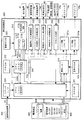
図3は、本実施形態の遊技機10の制御システムのブロック図である。
遊技機10は遊技制御装置100を備え、遊技制御装置100は、遊技を統括的に制御する主制御装置(主基板)であって、遊技用マイクロコンピュータ(以下、遊技用マイコンと称する)111を有するCPU部110と、入力ポートを有する入力部120と、出力ポートやドライバなどを有する出力部130、CPU部110と入力部120と出力部130との間を接続するデータバス140などからなる。
FIG. 3 is a block diagram of the control system of the
The
上記CPU部110は、アミューズメントチップ(IC)と呼ばれる遊技用マイコン(CPU)111と、入力部120内の近接スイッチ用のインタフェースチップ(近接I/F)121からの信号(始動入賞検出信号)を論理反転して遊技用マイコン111に入力させるインバータなどからなる反転回路112と、水晶振動子のような発振子を備え、CPUの動作クロックやタイマ割込み、乱数生成回路の基準となるクロックを生成する発振回路(水晶発振器)113などを有する。遊技制御装置100及び該遊技制御装置100によって駆動されるソレノイドやモータなどの電子部品には、電源装置400で生成されたDC32V,DC12V,DC5Vなど所定のレベルの直流電圧が供給されて動作可能にされる。
The
電源装置400は、24Vの交流電源から上記DC32Vの直流電圧を生成するAC−DCコンバータやDC32Vの電圧からDC12V,DC5Vなどのより低いレベルの直流電圧を生成するDC−DCコンバータなどを有する通常電源部410と、遊技用マイコン111の内部のRAMに対して停電時に電源電圧を供給するバックアップ電源部420と、停電監視回路や初期化スイッチを有し遊技制御装置100に停電の発生、回復を知らせる停電監視信号や初期化スイッチ信号、リセット信号などの制御信号を生成して出力する制御信号生成部430などを備える。
The
この実施形態では、電源装置400は、遊技制御装置100と別個に構成されているが、バックアップ電源部420及び制御信号生成部430は、別個の基板上あるいは遊技制御装置100と一体、即ち、主基板上に設けるように構成してもよい。遊技盤30及び遊技制御装置100は機種変更の際に交換の対象となるので、実施例のように、電源装置400若しくは主基板とは別の基板にバックアップ電源部420及び制御信号生成部430を設けることにより、交換の対象から外しコストダウンを図ることができる。
In this embodiment, the
上記バックアップ電源部420は、電解コンデンサのような大容量のコンデンサ1つで構成することができる。バックアップ電源は、遊技制御装置100の遊技用マイコン111(特に内蔵RAM)に供給され、停電中あるいは電源遮断後もRAMに記憶されたデータが保持されるようになっている。制御信号生成部430は、例えば通常電源部410で生成された32Vの電圧を監視してそれが例えば17V以下に下がると停電発生を検出して停電監視信号を変化させるとともに、所定時間後にリセット信号を出力する。また、電源投入時や停電回復時にもその時点から所定時間経過後にリセット信号を出力する。
The backup
初期化スイッチ信号は初期化スイッチがオン状態にされたときに生成される信号で、遊技用マイコン111内のRAM111C及び払出制御装置200内のRAMに記憶されている情報を強制的に初期化する。特に限定されるわけではないが初期化スイッチ信号は電源投入時に読み込まれ、停電監視信号は遊技用マイコン111が実行するメインプログラムのメインループの中で繰り返し読み込まれる。リセット信号は強制割込み信号の一種であり、制御システム全体をリセットさせる。
The initialization switch signal is a signal generated when the initialization switch is turned on, and forcibly initializes information stored in the
遊技用マイコン111は、遊技を統括的に制御する制御手段を構成している。具体的には、遊技用マイコン111は、CPU(中央処理ユニット:マイクロプロセッサ)111A、読出し専用のROM(リードオンリメモリ)111B及び随時読出し書込み可能なRAM(ランダムアクセスメモリ)111Cを備える。
The
ROM111Bは、遊技制御のための不変の情報(プログラム、固定データ、各種乱数の判定値等)を不揮発的に記憶し、RAM111Cは、遊技制御時にCPU111Aの作業領域や各種信号や乱数値の記憶領域として利用される。ROM111B又はRAM111Cとして、EEPROMのような電気的に書換え可能な不揮発性メモリを用いてもよい。
The
また、ROM111Bは、例えば、特図変動表示ゲームの実行時間、演出内容、リーチ状態の発生の有無などを規定する変動パターンを決定するための変動パターンテーブルを記憶している。
変動パターンテーブルとは、始動記憶として記憶されている変動パターン乱数1〜3をCPU111Aが参照して変動パターンを決定するためのテーブルである。また、変動パターンテーブルには、結果がはずれとなる場合に選択されるはずれ変動パターンテーブル、結果が15R確変当りや2R確変当りとなる場合に選択される大当り変動パターンテーブル等が含まれる。
In addition, the
The variation pattern table is a table for the
また、リーチ(リーチ状態)とは、表示状態が変化可能な表示装置を有し、該表示装置が時期を異ならせて複数の表示結果を導出表示し、該複数の表示結果が予め定められた特別結果態様となった場合に、遊技状態が遊技者にとって有利な遊技状態(特別遊技状態)となる遊技機10において、複数の表示結果の一部がまだ導出表示されていない段階で、既に導出表示されている表示結果が特別結果態様となる条件を満たしている表示状態をいう。また、別の表現をすれば、リーチ状態とは、表示装置の変動表示制御が進行して表示結果が導出表示される前段階にまで達した時点でも、特別結果態様となる表示条件からはずれていない表示態様をいう。そして、例えば、特別結果態様が揃った状態を維持しながら複数の変動表示領域による変動表示を行う状態(いわゆる全回転リーチ)もリーチ状態に含まれる。また、リーチ状態とは、表示装置の表示制御が進行して表示結果が導出表示される前段階にまで達した時点での表示状態であって、表示結果が導出表示される以前に決定されている複数の変動表示領域の表示結果の少なくとも一部が特別結果態様となる条件を満たしている場合の表示状態をいう。
Reach (reach state) has a display device whose display state can change, and the display device derives and displays a plurality of display results at different times, and the plurality of display results are predetermined. In the
よって、例えば、特図変動表示ゲームに対応して表示装置に表示される飾り特図変動表示ゲームが、表示装置における左、中、右の変動表示領域の各々で所定時間複数の識別情報を変動表示した後、左、右、中の順で変動表示を停止して結果態様を表示するものである場合、左、右の変動表示領域で、特別結果態様となる条件を満たした状態(例えば、同一の識別情報)で変動表示が停止した状態がリーチ状態となる。またこの他に、すべての変動表示領域の変動表示を一旦停止した時点で、左、中、右のうち何れか二つの変動表示領域で特別結果態様となる条件を満たした状態(例えば、同一の識別情報となった状態、ただし特別結果態様は除く)をリーチ状態とし、このリーチ状態から残りの一つの変動表示領域を変動表示するようにしても良い。そして、このリーチ状態には複数のリーチ演出が含まれ、特別結果態様が導出される可能性が異なる(信頼度が異なる)リーチ演出として、ノーマルリーチ、スペシャル1リーチ、スペシャル2リーチ、スペシャル3リーチ等が設定されている。 Thus, for example, a decorative special figure fluctuation display game displayed on a display device corresponding to a special figure fluctuation display game fluctuates a plurality of identification information for a predetermined time in each of the left, middle, and right fluctuation display areas on the display device. After displaying, when the display of the result mode is stopped in the order of left, right, and middle, the condition that becomes the special result mode is satisfied in the left and right variable display areas (for example, The state in which the variable display is stopped with the same identification information) is the reach state. In addition to this, when the variable display of all the variable display areas is temporarily stopped, the condition that the special result mode is satisfied in any two of the left, middle, and right variable display areas (for example, the same The state in which the identification information is obtained (except for the special result mode) may be set as the reach state, and the remaining one variable display area may be variably displayed from the reach state. This reach state includes a plurality of reach effects, and the possibility of deriving a special result mode is different (having different reliability), such as normal reach, special 1 reach, special 2 reach, special 3 reach, etc. Is set.
なお、信頼度は、リーチなし<ノーマルリーチ<スペシャル1リーチ<スペシャル2リーチ<スペシャル3リーチの順に高くなるようになっている。また、このリーチ状態は、少なくとも特図変動表示ゲームで特別結果態様が導出される場合(大当りとなる場合)における変動表示態様に含まれるようになっている。即ち、特図変動表示ゲームで特別結果態様が導出されないと判定する場合(はずれとなる場合)における変動表示態様に含まれることもある。よって、リーチ状態が発生した状態は、リーチ状態が発生しない場合に比べて大当りとなる可能性の高い状態である。 The reliability increases in the order of no reach <normal reach <special 1 reach <special 2 reach <special 3 reach. In addition, this reach state is included in a variable display mode at least in a case where a special result mode is derived in a special figure variable display game (when a big hit is achieved). That is, it may be included in the variable display mode when it is determined that the special result mode is not derived in the special figure variable display game (when it is out of place). Therefore, the state in which the reach state has occurred is a state that is more likely to be a big hit than the case in which the reach state does not occur.
CPU111Aは、ROM111B内の遊技制御用プログラムを実行して、払出制御装置200や演出制御装置300に対する制御信号(コマンド)を生成したりソレノイドや表示装置の駆動信号を生成して出力して遊技機10全体の制御を行う。
また、図示しないが、遊技用マイコン111は、特図変動表示ゲームの大当り判定用乱数や大当りの図柄を決定するための大当り図柄用乱数、普図変動表示ゲームの当り判定用乱数等を生成するための乱数生成回路と、発振回路113からの発振信号(原クロック信号)に基づいてCPU111Aに対する所定周期(例えば、4ミリ秒)のタイマ割込み信号や乱数生成回路の更新タイミングを与えるクロックを生成するクロックジェネレータを備えている。
The
Although not shown, the
また、CPU111Aは、特図ゲーム処理における始動口スイッチ監視処理や特図普段処理にて、ROM111Bに記憶されている複数の変動パターンテーブルの中から、何れか一の変動パターンテーブルを取得する。具体的には、CPU111Aは、特図変動表示ゲームの遊技結果(大当り或いははずれ)や、現在の遊技状態としての特図変動表示ゲームの確率状態(通常確率状態或いは高確率状態)、現在の遊技状態としての普通変動入賞装置37の動作状態(通常動作状態或いは時短動作状態)、始動記憶数などに基づいて、複数の変動パターンテーブルの中から、何れか一の変動パターンテーブルを選択して取得する。
Further, the
払出制御装置200は、図示しないが、CPU、ROM、RAM、入力インタフェース、出力インタフェース等を備え、遊技制御装置100からの賞球払出し指令(コマンドやデータ)に従って、払出ユニットの払出モータを駆動させ、賞球を払い出させるための制御を行う。また、払出制御装置200は、カードユニットからの貸球要求信号に基づいて払出ユニットの払出モータを駆動させ、貸球を払い出させるための制御を行う。
Although not shown, the
遊技用マイコン111の入力部120には、始動入賞口36内の始動口1スイッチ36a、普通変動入賞装置37内の始動口2スイッチ37a、普図始動ゲート34内のゲートスイッチ34a、一般入賞口スイッチ35a〜35n、カウントスイッチ38aに接続され、これらのスイッチから供給されるハイレベルが11Vでロウレベルが7Vのような負論理の信号が入力され、0V−5Vの正論理の信号に変換するインタフェースチップ(近接I/F)121が設けられている。近接I/F121は、入力の範囲が7V−11Vとされることで、近接スイッチのリード線が不正にショートされたり、スイッチがコネクタから外されたり、リード線が切断されてフローティングになったような異常な状態を検出することができ、異常検知信号を出力するように構成されている。
The
近接I/F121の出力はすべて第2入力ポート122へ供給されデータバス140を介して遊技用マイコン111に読み込まれるとともに、主基板100から中継基板70を介して図示しない試射試験装置へ供給されるようになっている。また、近接I/F121の出力のうち始動口1スイッチ36aと始動口2スイッチ37aの検出信号は、第2入力ポート122の他、反転回路112を介して遊技用マイコン111へ入力されるように構成されている。反転回路112を設けているのは、遊技用マイコン111の信号入力端子が、マイクロスイッチなどからの信号が入力されることを想定し、かつ負論理、即ち、ロウレベル(0V)を有効レベルとして検知するように設計されているためである。
All the outputs of the proximity I /
従って、始動口1スイッチ36aと始動口2スイッチ37aとしてマイクロスイッチを使用する場合には、反転回路112を設けずに直接遊技用マイコン111へ検出信号を入力させるように構成することができる。つまり、始動口1スイッチ36aと始動口2スイッチ37aからの負論理の信号を直接遊技用マイコン111へ入力させたい場合には、近接スイッチを使用することはできない。上記のように近接I/F121は、信号のレベル変換機能を有する。このようなレベル変換機能を可能にするため、近接I/F121には、電源装置400から通常のICの動作に必要な例えば5Vのような電圧の他に、12Vの電圧が供給されるようになっている。
Therefore, when a micro switch is used as the start port 1
また、入力部120には、遊技機10の前面枠12等に設けられた不正検出用の磁気センサスイッチ61及び振動センサスイッチ62からの信号及び上記近接I/F121により変換された始動入賞口36内の始動口1スイッチ36a、普通変動入賞装置37内の始動口2スイッチ37a、ゲートスイッチ34a、一般入賞口スイッチ35a〜35n、カウントスイッチ38aからの信号を取り込んでデータバス140を介して遊技用マイコン111に供給する第2入力ポート122が設けられている。第2入力ポート122が保持しているデータは、遊技用マイコン111が第2入力ポート122に割り当てられているアドレスをデコードすることによってイネーブル信号CE1をアサート(有効レベルに変化)することよって、読み出すことができる。後述の他のポートも同様である。
Further, the
さらに、入力部120には、遊技機10のガラス枠15等に設けられた前枠開放検出スイッチ63及び前面枠(遊技枠)12等に設けられた遊技枠開放検出スイッチ64からの信号及び払出制御装置200からの払出異常を示すステータス信号や払出し前の遊技球の不足を示すシュート球切れスイッチ信号、オーバーフローを示すオーバーフロースイッチ信号を取り込んでデータバス140を介して遊技用マイコン111に供給する第1入力ポート123が設けられている。オーバーフロースイッチ信号は、下皿23に遊技球が所定量以上貯留されていること(満杯になったこと)を検出したときに出力される信号である。
Further, the
また、入力部120には、電源装置400からの停電監視信号や初期化スイッチ信号、リセット信号などの信号を遊技用マイコン111等に入力するためのシュミットトリガ回路124が設けられており、シュミットトリガ回路124はこれらの入力信号からノイズを除去する機能を有する。電源装置400からの信号のうち停電監視信号と初期化スイッチ信号は、一旦第1入力ポート123に入力され、データバス140を介して遊技用マイコン111に取り込まれる。つまり、前述の各種スイッチからの信号と同等の信号として扱われる。遊技用マイコン111に設けられている外部からの信号を受ける端子の数には制約があるためである。
Further, the
一方、シュミットトリガ回路124によりノイズ除去されたリセット信号RSTは、遊技用マイコン111に設けられているリセット端子に直接入力されるとともに、出力部130の各ポートに供給される。また、リセット信号RSTは出力部130を介さずに直接中継基板70に出力することで、試射試験装置へ出力するために中継基板70のポート(図示省略)に保持される試射試験信号をオフするように構成されている。また、リセット信号RSTを中継基板70を介して試射試験装置へ出力可能に構成するようにしてもよい。なお、リセット信号RSTは入力部120の各ポート122,123には供給されない。リセット信号RSTが入る直前に遊技用マイコン111によって出力部130の各ポートに設定されたデータはシステムの誤動作を防止するためリセットする必要があるが、リセット信号RSTが入る直前に入力部120の各ポートから遊技用マイコン111が読み込んだデータは、遊技用マイコン111のリセットによって廃棄されるためである。
On the other hand, the reset signal RST from which noise has been removed by the
出力部130は、データバス140に接続され払出制御装置200へ出力する4ビットのデータ信号とデータの有効/無効を示す制御信号(データストローブ信号)及び演出制御装置300へ出力するデータストローブ信号SSTBを生成する第1出力ポート131と、演出制御装置300へ出力する8ビットのデータ信号を生成する第2出力ポート132とを備える。遊技制御装置100から払出制御装置200及び演出制御装置300へは、パラレル通信でデータが送信される。また、出力部130には、演出制御装置300の側から遊技制御装置100へ信号を入力できないようにするため、即ち、片方向通信を担保するために第1出力ポート131からの上記データストローブ信号SSTB及び第2出力ポート132からの8ビットのデータ信号を出力する単方向のバッファ133が設けられている。なお、第1出力ポート131から払出制御装置200へ出力する信号に対してもバッファを設けるようにしてもよい。
The output unit 130 is connected to the
さらに、出力部130には、データバス140に接続され図示しない認定機関の試射試験装置へ変動表示ゲームの特図図柄情報を知らせるデータや大当りの確率状態を示す信号などを中継基板70を介して出力するバッファ134が実装可能に構成されている。このバッファ134は遊技店に設置される実機(量産販売品)としてのパチンコ遊技機の遊技制御装置(主基板)には実装されない部品である。なお、前記近接I/F121から出力される始動口スイッチなど加工の必要のないスイッチの検出信号は、バッファ134を通さずに中継基板70を介して試射試験装置へ供給される。
In addition, the output unit 130 is connected to the
一方、磁気センサスイッチ61や振動センサスイッチ62のようにそのままでは試射試験装置へ供給できない検出信号は、一旦遊技用マイコン111に取り込まれて他の信号若しくは情報に加工されて、例えば遊技機が遊技制御できない状態であることを示すエラー信号としてデータバス140からバッファ134、中継基板70を介して試射試験装置へ供給される。なお、中継基板70には、上記バッファ134から出力された信号を取り込んで試射試験装置へ供給するポートや、バッファを介さないスイッチの検出信号の信号線を中継して伝達するコネクタなどが設けられている。中継基板70上のポートには、遊技用マイコン111から出力されるチップイネーブル信号CEも供給され、該信号CEにより選択制御されたポートの信号が試射試験装置へ供給されるようになっている。
On the other hand, detection signals such as the
また、出力部130には、データバス140に接続され特別変動入賞装置38を開成させるソレノイド(大入賞口ソレノイド)38bや普通変動入賞装置37の可動部材37bを開成させるソレノイド(普電ソレノイド)37cの開閉データと、一括表示装置のLEDのカソード端子が接続されているデジット線のオン/オフデータを出力するための第3出力ポート135、一括表示装置に表示する内容に応じてLEDのアノード端子が接続されているセグメント線のオン/オフデータを出力するための第4出力ポート136、大当り情報など遊技機10に関する情報を外部情報端子71へ出力するための第5出力ポート137が設けられている。外部情報端子71から出力された遊技機10に関する情報は、例えば遊技店に設置された情報収集端末や遊技場内部管理装置(図示省略)に供給される。
In addition, the output unit 130 is connected to the
さらに、出力部130には、第3出力ポート135から出力される大入賞口ソレノイド38bの開閉データ信号を受けてソレノイド駆動信号や普電ソレノイド37cの開閉データ信号を受けてソレノイド駆動信号を生成し出力する第1ドライバ(駆動回路)138a、第3出力ポート135から出力される一括表示装置の電流引き込み側のデジット線のオン/オフ駆動信号を出力する第2ドライバ138b、第4出力ポート136から出力される一括表示装置の電流供給側のセグメント線のオン/オフ駆動信号を出力する第3ドライバ138c、第5出力ポート137から管理装置等の外部装置へ供給する外部情報信号を外部情報端子71へ出力する第4ドライバ138dが設けられている。
Further, the output unit 130 receives the opening / closing data signal of the big
上記第1ドライバ138aには、32Vで動作するソレノイドを駆動できるようにするため、電源電圧としてDC32Vが電源装置400から供給される。また、一括表示装置のセグメント線を駆動する第3ドライバ138cには、DC12Vが供給される。デジット線を駆動する第2ドライバ138bは、表示データに応じたデジット線を電流で引き抜くためのものであるため、電源電圧は12V又は5Vのいずれであってもよい。12Vを出力する第3ドライバ138cによりセグメント線を介してLEDのアノード端子に電流を流し込み、接地電位を出力する第2ドライバ138bによりカソード端子よりセグメント線を介して電流を引き抜くことで、ダイナミック駆動方式で順次選択されたLEDに電源電圧が流れて点灯される。外部情報信号を外部情報端子71へ出力する第4ドライバ138dは、外部情報信号に12Vのレベルを与えるため、DC12Vが供給される。なお、バッファ134や第3出力ポート135、第1ドライバ138a等は、遊技制御装置100の出力部130、即ち、主基板ではなく、中継基板70側に設けるようにしてもよい。
The first driver 138a is supplied with DC32V from the
さらに、出力部130には、外部の検査装置500へ各遊技機の識別コードやプログラムなどの情報を送信するためのフォトカプラ139が設けられている。フォトカプラ139は、遊技用マイコン111が検査装置500との間でシリアル通信によってデータの送受信を行えるように双方通信可能に構成されている。なお、かかるデータの送受信は、通常の汎用マイクロプロセッサと同様に遊技用マイコン111が有するシリアル通信端子を利用して行われるため、入力ポート122,123のようなポートは設けられていない。
Further, the output unit 130 is provided with a
次に、図4を用いて、演出制御装置300の構成について説明する。
演出制御装置300は、遊技用マイコン111と同様にアミューズメントチップ(IC)からなる主制御用マイコン(1stCPU)311と、該1stCPU311の制御下でもっぱら映像制御を行う映像制御用マイコン(2ndCPU)312と、該2ndCPU312からのコマンドやデータに従って表示装置41への映像表示のための画像処理を行うグラフィックプロセッサとしてのVDP(Video Display Processor)313と、各種のメロディや効果音などをスピーカ19a,19bから再生させるため音の出力を制御する音源LSI314を備えている。
Next, the configuration of the
The
上記主制御用マイコン(1stCPU)311と映像制御用マイコン(2ndCPU)312には、各CPUが実行するプログラムを格納したPROM(プログラマブルリードオンリメモリ)からなるプログラムROM321、322がそれぞれ接続され、VDP313にはキャラクタ画像や映像データが記憶された画像ROM323が接続され、音源LSI314には音声データが記憶された音声ROM324が接続されている。主制御用マイコン(1stCPU)311は、遊技用マイコン111からのコマンドを解析し、演出内容を決定して映像制御用マイコン312へ出力映像の内容を指示したり、音源LSI314への再生音の指示、装飾ランプの点灯、モータの駆動制御、演出時間の管理などの処理を実行する。主制御用マイコン(1stCPU)311と映像制御用マイコン(2ndCPU)312の作業領域を提供するRAMは、それぞれのチップ内部に設けられている。なお、作業領域を提供するRAMはチップの外部に設けるようにしてもよい。
The main control microcomputer (1st CPU) 311 and the video control microcomputer (2nd CPU) 312 are connected to program
特に限定されるわけではないが、主制御用マイコン(1stCPU)311と映像制御用マイコン(2ndCPU)312との間、主制御用マイコン(1stCPU)311と音源LSI314との間は、それぞれシリアル方式でデータの送受信が行われ、映像制御用マイコン(2ndCPU)312との間、主制御用マイコン(1stCPU)311とVDP313との間は、パラレル方式でデータの送受信が行われるように構成されている。パラレル方式でデータを送受信することで、シリアルの場合よりも短時間にコマンドやデータを送信することができる。VDP313には、画像ROM323から読み出されたキャラクタなどの画像データを展開したり加工したりするのに使用される超高速なVRAM(ビデオRAM)313aや、画像を拡大、縮小処理するためのスケーラ313b、LVDS(小振幅信号伝送)方式で表示装置41へ送信する映像信号を生成する信号変換回路313cなどが設けられている。
Although not particularly limited, a serial system is used between the main control microcomputer (1st CPU) 311 and the video control microcomputer (2nd CPU) 312 and between the main control microcomputer (1st CPU) 311 and the
VDP313から主制御用マイコン311へは表示装置41の映像と前面枠12や遊技盤30に設けられている装飾ランプの点灯を同期させるために垂直同期信号VSYNCが入力される。さらに、VDP313から映像制御用マイコン312へは、VRAMへの描画の終了等処理状況を知らせるため割込み信号INT0〜n及び映像制御用マイコン312からのコマンドやデータの受信待ちの状態にあることを知らせるためのウェイト信号WAITが入力される。また、映像制御用マイコン312から主制御用マイコン311へは、映像制御用マイコン312が正常に動作していることを知らせるとともにコマンドの送信タイミングを与える同期信号SYNCが入力される。主制御用マイコン311と音源LSI314との間は、ハンドシェイク方式でコマンドやデータの送受信を行うために、呼び掛け(コール)信号CTSと応答(レスポンス)信号RTSが交換される。
A vertical synchronization signal VSYNC is input from the
なお、映像制御用マイコン(2ndCPU)312には、主制御用マイコン(1stCPU)311よりも高速なつまり高価なCPUが使用されている。主制御用マイコン(1stCPU)311とは別に映像制御用マイコン(2ndCPU)312を設けて処理を分担させることによって、主制御用マイコン(1stCPU)311のみでは実現困難な大画面で動きの速い映像を表示装置41に表示させることが可能となるとともに、映像制御用マイコン(2ndCPU)312と同等な処理能力を有するCPUを2個使用する場合に比べてコストの上昇を抑制することができる。また、CPUを2つ設けることによって、2つのCPUの制御プログラムを別々に並行して開発することが可能となり、これによって新機種の開発期間を短縮することができる。
Note that the video control microcomputer (2ndCPU) 312 uses a CPU that is faster or more expensive than the main control microcomputer (1stCPU) 311. By providing a video control microcomputer (2ndCPU) 312 separately from the main control microcomputer (1stCPU) 311 and sharing the processing, it is possible to display a fast moving image on a large screen that is difficult to achieve with the main control microcomputer (1stCPU) 311 alone. It is possible to display on the
また、演出制御装置300には、遊技制御装置100から送信されてくるコマンドを受信するインタフェースチップ(コマンドI/F)331が設けられている。このコマンドI/F331を介して、遊技制御装置100から演出制御装置300へ送信された変動開始コマンド、始動口入賞演出コマンド、始動口入賞演出図柄コマンド、客待ちデモコマンド、ファンファーレコマンド、確率情報コマンド、変動停止コマンド、大当り終了コマンド、エラー指定コマンド等を、演出制御指令信号として受信する。遊技制御装置100の遊技用マイコン111はDC5Vで動作し、演出制御装置300の主制御用マイコン(1stCPU)311はDC3.3Vで動作するため、コマンドI/F331には信号のレベル変換の機能が設けられている。
In addition, the
また、演出制御装置300には、遊技盤30(センターケース40を含む)に設けられているLED(発光ダイオード)を有する盤装飾装置42を駆動制御する盤装飾LED制御回路332、前面枠12に設けられているLED(発光ダイオード)を有する枠装飾装置(例えば枠装飾装置18等)を駆動制御する枠装飾LED制御回路333、遊技盤30(センターケース40を含む)に設けられている盤演出装置44(例えば表示装置41における演出表示と協働して演出効果を高める電動役物等)を駆動制御する盤演出モータ/SOL制御回路334、前面枠12に設けられている枠演出装置45(例えば前記ムービングライト16を動作させるモータ等)を駆動制御する枠演出モータ制御回路335が設けられている。なお、ランプやモータ及びソレノイドなどを駆動制御するこれらの制御回路332〜335は、アドレス/データバス340を介して主制御用マイコン(1stCPU)311と接続されている。
The
さらに、演出制御装置300には、前面枠12に設けられた演出ボタン25に内蔵されているスイッチ25aや上記盤演出装置44内のモータの初期位置を検出する演出モータスイッチのオン/オフ状態を検出して主制御用マイコン(1stCPU)311へ検出信号を入力するスイッチ入力回路336、前面枠12に設けられた上スピーカ19aを駆動するオーディオパワーアンプなどからなるアンプ回路337a、前面枠12に設けられた下スピーカ19bを駆動するアンプ回路337bが設けられている。
Further, the
電源装置400の通常電源部410は、上記のような構成を有する演出制御装置300やそれによって制御される電子部品に対して所望のレベルの直流電圧を供給するため、モータやソレノイドを駆動するためのDC32V、液晶パネル等からなる表示装置41を駆動するためのDC12V、コマンドI/F331の電源電圧となるDC5Vの他に、LEDやスピーカを駆動するためのDC18Vやこれらの直流電圧の基準としたり電源モニタランプを点灯させるのに使用するNDC24Vの電圧を生成するように構成されている。さらに、主制御用マイコン(1stCPU)311や映像制御用マイコン(2ndCPU)312として、3.3Vあるいは1.2Vのような低電圧で動作するLSIを使用する場合には、DC5Vに基づいてDC3.3VやDC1.2Vを生成するためのDC−DCコンバータが演出制御装置300に設けられる。なお、DC−DCコンバータは通常電源部410に設けるようにしてもよい。
The normal
電源装置400の制御信号生成部430により生成されたリセット信号RSTは、主制御用マイコン311、映像制御用マイコン312、VDP313、音源LSI314、ランプやモータなどを駆動制御する制御回路332〜335、スピーカを駆動するアンプ回路337a,337bに供給され、これらをリセット状態にする。また、この実施例においては、映像制御用マイコン312の有する汎用のポートを利用して、VDP313に対するリセット信号を生成して供給する機能を有するように構成されている。これにより、映像制御用マイコン312とVDP313の動作の連携性を向上させることができる。
The reset signal RST generated by the control
次に、これらの制御回路において行われる遊技制御について説明する。
遊技制御装置100の遊技用マイコン111のCPU111Aでは、普図始動ゲート34に備えられたゲートスイッチ34aからの遊技球の検出信号の入力に基づき、普図の当り判定用乱数値を抽出してROM111Bに記憶されている判定値と比較し、普図変動表示ゲームの当りはずれを判定する処理を行う。そして、普図表示器に、識別情報を所定時間変動表示した後、停止表示する普図変動表示ゲームを表示する処理を行う。この普図変動表示ゲームの結果が当りの場合は、普図表示器に特別の結果態様を表示するとともに、普電ソレノイド37cを動作させ、普通変動入賞装置37の可動部材37b,37bを所定時間(例えば、0.3秒間)前述のように開放する制御を行う。
なお、普図変動表示ゲームの結果がはずれの場合は、普図表示器にはずれの結果態様を表示する制御を行う。
Next, game control performed in these control circuits will be described.
The
In addition, when the result of the normal map change display game is out of control, control is performed to display the result form of the shift on the general map display.
また、始動入賞口36に備えられた始動口1スイッチ36aからの遊技球の検出信号の入力に基づき始動入賞(始動記憶)をRAM111C等に記憶し、この始動記憶に基づき、第1特図変動表示ゲームの大当り判定用乱数値を抽出してROM111Bに記憶されている判定値と比較し、第1特図変動表示ゲームの当りはずれを判定する処理を行う。
また、普通変動入賞装置37に備えられた始動口2スイッチ37aからの遊技球の検出信号の入力に基づき始動記憶をRAM111C等に記憶し、この始動記憶に基づき、第2特図変動表示ゲームの大当り判定用乱数値を抽出してROM111Bに記憶されている判定値と比較し、第2特図変動表示ゲームの当りはずれを判定する処理を行う。
Further, based on the input of the game ball detection signal from the start port 1
In addition, the start memory is stored in the
そして、遊技制御装置100のCPU111Aは、上記の第1特図変動表示ゲームや第2特図変動表示ゲームの判定結果を含む制御信号(演出制御コマンド)を、演出制御装置300に出力する。そして、第1特図表示器や第2特図表示器に、識別情報を所定時間変動表示した後、停止表示する特図変動表示ゲームを表示する処理を行う。
また、演出制御装置300では、遊技制御装置100からの制御信号に基づき、表示装置41で特図変動表示ゲームに対応した飾り特図変動表示ゲームを表示する処理を行う。
さらに、演出制御装置300では、遊技制御装置100からの制御信号に基づき、スピーカ19a,19bからの音の出力、各種LEDの発光を制御する処理等を行う。
Then, the
In addition, in the
Furthermore, in the
そして、遊技制御装置100のCPU111Aは、特図変動表示ゲームの結果が大当りの場合は、第1特図表示器や第2特図表示器に特別結果態様を表示するとともに、特別遊技状態を発生させる処理を行う。
例えば、この特図変動表示ゲームの結果として、第1特図表示器もしくは第2特図表示器の表示態様が特別結果態様(例えば「7」)となった場合には、大当りとなって特別遊技状態(いわゆる、大当り状態)となる。
Then, the
For example, if the display form of the first special figure display or the second special figure display becomes a special result form (for example, “7”) as a result of the special figure fluctuation display game, a special hit is given. It becomes a gaming state (so-called big hit state).
特別遊技状態を発生させる処理においては、CPU111Aは、例えば、大入賞口ソレノイド38bにより特別変動入賞装置38の開閉扉38cを開放させ、大入賞口内への遊技球の流入を可能とする制御を行う。
そして、特図変動表示ゲームの結果が大当りの場合は、大入賞口に所定個数(例えば、10個)の遊技球が入賞するか、大入賞口の開放から所定時間(例えば、25秒又は0.5秒)が経過するかの何れかの条件が達成されるまで大入賞口を開放することを1ラウンドとし、これを所定ラウンド回数(例えば、15回又は2回)継続する(繰り返す)制御(サイクル遊技)を行う。
また、特図変動表示ゲームの結果がはずれの場合は、第1特図表示器や第2特図表示器にはずれの結果態様を表示する制御を行う。
In the process of generating the special game state, the
Then, when the result of the special figure variation display game is a big hit, a predetermined number (for example, 10) of game balls wins the big winning opening, or a predetermined time (for example, 25 seconds or 0) from the opening of the big winning opening. .5 seconds) until one of the conditions is achieved, a round is defined as opening a winning prize opening, and this is repeated (repeated) for a predetermined number of rounds (for example, 15 or 2 times). (Cycle game) is performed.
When the result of the special figure variation display game is out of order, control is performed to display the result form of the deviation on the first special figure display or the second special figure display.
また、遊技制御装置100は、特図変動表示ゲームの結果態様に基づき、特別遊技状態の終了後に、遊技状態として確変状態を発生可能となっている。
この確変状態は、特図変動表示ゲームにて当り結果となる確率が、通常確率状態に比べて高い状態(高確率状態)である。また、第1特図変動表示ゲーム及び第2特図変動表示ゲームのどちらの特図変動表示ゲームの結果態様に基づき確変状態となっても、第1特図変動表示ゲーム及び第2特図変動表示ゲームの両方が確変状態となる。
In addition, the
This probability variation state is a state (high probability state) in which the probability of a hit result in the special figure variation display game is higher than the normal probability state. In addition, the first special figure variation display game and the second special figure variation display game, regardless of which one of the first special figure variation display game and the second special figure variation display game results in a certain variation state. Both display games are in a probable state.
また、遊技制御装置100は、特図変動表示ゲームの結果態様に基づき、特別遊技状態の終了後に、遊技状態として時短状態を発生可能となっている。
この時短状態においては、普図変動表示ゲーム及び普通変動入賞装置37を時短動作状態とする制御を行う。具体的には、時短状態においては、前述の普図変動表示ゲームの実行時間が第1の変動表示時間よりも短い第2の変動表示時間となるように制御され(例えば、10秒が1秒)、これにより、単位時間当りの普通変動入賞装置37の開放回数が実質的に多くなるように制御される。また、時短状態においては、普図変動表示ゲームが当り結果となって普通変動入賞装置37が開放される場合に、開放時間が通常状態の第1開放時間よりも長い第2開放時間となるように制御される(例えば、0.3秒が1.7秒)。また、時短状態においては、普図変動表示ゲームの1回の当り結果に対して、普通変動入賞装置37の開放回数が1回の第1開放回数ではなく、2回以上の複数回(例えば、3回)の第2開放回数に設定される。
なお、普図変動表示ゲームの実行時間を第2の変動表示時間(例えば、1秒)とする制御と、普通変動入賞装置37の開放態様を開放時間が第2開放時間(例えば、1.7秒)とし、且つ、普図変動表示ゲームの1回の当り結果に対する開放回数が第2開放回数(例えば、3回)とする制御は、何れか一方のみを行っても良いし、両方を行っても良い。また、時短動作状態においては、普図変動表示ゲームの当り結果となる確率が通常動作状態より高くなるように制御してもよい。
これにより、普通変動入賞装置37に遊技球が入賞し易くなり、第2特図変動表示ゲームの始動が容易となる。
In addition, the
In this time-short state, control is performed so that the normal-variation display game and the normal
It should be noted that the execution time of the normal variation display game is set to the second variation display time (for example, 1 second), and the release mode of the normal
As a result, the game ball can easily win the normal
なお、確変状態と普図変動表示ゲーム及び普通変動入賞装置37の時短動作状態は、それぞれ独立して発生可能であり、両方を同時に発生することも可能であるし、一方のみを発生させることも可能である。
In addition, the time variation operation state of the probability variation state, the normal variation display game, and the normal variation
次に、本実施形態の遊技機10が特徴とする戻り球防止手段80について説明する。
遊技機10は、図2や図5や図6に示すように、発射制御装置210(図3参照)によって制御される打球発射装置(発射装置)により弾発された遊技球を遊技領域32内に案内する円弧状の発射流路Rを有している。この発射流路Rは、遊技領域32を区画する内レール部材31bの外面と、当該内レール部材31bの外側に配設された外レール部材31aの内面との間に形成されている。
そして、遊技機10は、発射流路Rの先端出口部分に戻り球防止手段80を備えている。
Next, the return ball prevention means 80 characterized by the
As shown in FIG. 2, FIG. 5, or FIG. 6, the
The
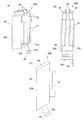
戻り球防止手段80は、一枚の金属板を塑性加工することによって形成されている。
具体的には、戻り球防止手段80は、図7(A)〜(E)や図8(A),(B)や図9(A),(B)に示すように、常態において発射流路Rを塞ぐ方向に各々延出して観音開き状に開閉可能な一対の戻り球防止弁81,81と、当該戻り球防止手段80を発射流路Rの先端出口部分に取り付けるための取付部82,82と、戻り球防止弁81,81及び取付部82,82が設けられたベース部材83とを備えて構成される。
なお、図7〜図13では、便宜上、実際よりも厚みのある金属板で形成された戻り球防止手段80を図示しているが、戻り球防止手段80を形成する金属板の厚さは、実際は0.1mm前後である。
The return ball preventing means 80 is formed by plastic working a single metal plate.
Specifically, as shown in FIGS. 7A to 7E, FIGS. 8A and 8B, and FIGS. 9A and 9B, the return ball preventing means 80 is normally launched in the normal state. A pair of return
In addition, in FIGS. 7-13, although the return ball | bowl prevention means 80 formed with the metal plate thicker than actual is shown for convenience, the thickness of the metal plate which forms the return sphere prevention means 80 is as follows. Actually, it is around 0.1 mm.
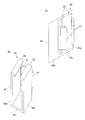
ベース部材83は、図5や図6に示すように、発射流路Rの先端出口部分の遊技盤30側とカバーガラス14(透明部材)側とのそれぞれを覆うように構成されている。
具体的には、ベース部材83は、図7(A)〜(E)や図8(A),(B)や図9(A),(B)に示すように、発射流路Rの先端出口部分の遊技盤30側を覆う略平行四辺形状の第1ベース本体部83aと、発射流路Rの先端出口部分のカバーガラス14側を覆う略平行四辺形状の第2ベース本体部83bと、当該第1ベース本体部83aの下端部(内レール部材31b側の端部)と当該第2ベース本体部83bの下端部(内レール部材31b側の端部)とを連結する略矩形状の連結部83cとを備えて構成される。
As shown in FIGS. 5 and 6, the
Specifically, as shown in FIGS. 7A to 7E, FIGS. 8A and 8B, and FIGS. 9A and 9B, the
戻り球防止手段80が発射流路Rの先端出口部分に正しく取り付けられた状態において、第1ベース本体部83aの左端部(発射流路R側の端部)及び右端部(遊技領域32側の端部)と、第2ベース本体部83bの左端部(発射流路R側の端部)及び右端部(遊技領域32側の端部)とは、遊技機10の上下方向に略沿っている。すなわち、戻り球防止手段80は、遊技機10の上下方向に略沿った状態で、発射流路Rの先端出口部分に取り付けられる。
In a state where the return ball preventing means 80 is correctly attached to the tip outlet portion of the firing flow path R, the left end portion (the end portion on the firing flow path R side) and the right end portion (on the
戻り球防止手段80が、遊技機10の上下方向に対して傾いた状態で、発射流路Rの先端出口部分に取り付けられる場合、発射流路Rから遊技領域32へと飛び出そうとする遊技球や、遊技領域32から発射流路Rへと戻ろうとする遊技球などが、戻り球防止手段80に載置される等して滞ってしまう虞がある。このような問題を回避するために、本実施形態では、戻り球防止手段80を、遊技機10の上下方向に略沿った状態で、発射流路Rの先端出口部分に取り付けるように構成している。
When the return ball prevention means 80 is attached to the tip outlet portion of the launch channel R in a state inclined with respect to the vertical direction of the
また、戻り球防止手段80が発射流路Rの先端出口部分に正しく取り付けられた状態において、連結部83cは、内レール部材31bの内面側(遊技領域32側)に配設されている。
そして、戻り球防止手段80が発射流路Rの先端出口部分に正しく取り付けられた状態において、連結部83cの上面(発射流路R側の面)と、内レール部材31bの内面とが略当接するように、第1ベース本体部83aの下端部(内レール部材31b側の端部)と、第2ベース本体部83bの下端部(内レール部材31b側の端部)とは、発射流路Rの先端出口部分における内レール部材31bの傾斜に略沿っている。
In addition, in a state where the return ball preventing means 80 is correctly attached to the tip outlet portion of the firing flow path R, the connecting
Then, in a state where the return ball prevention means 80 is correctly attached to the tip outlet portion of the firing channel R, the upper surface of the connecting
このように、戻り球防止手段80が発射流路Rの先端出口部分に正しく取り付けられた状態において、連結部83cの上面と、内レール部材31bの内面とが略当接するので、戻り球防止手段80の位置決めを的確に行うことが可能となる。したがって、戻り球防止手段80は正しい取り付け位置に装着されるので、より安定した遊技球の遊技領域32への飛び出しが可能となる。
Thus, in the state where the return ball prevention means 80 is correctly attached to the tip outlet portion of the firing flow path R, the upper surface of the connecting
取付部82,82は、ベース部材83の上端部(外レール部材31a側の端部)に設けられている。
具体的には、図7(A)〜(E)や図8(A),(B)や図9(A),(B)に示すように、取付部82,82のうちの一方は、ベース部材83を構成する第1ベース本体部83aの上端部(外レール部材31a側の端部)から前方(カバーガラス14の方)へ突出するように設けられている。また、取付部82,82のうちの他方は、ベース部材83を構成する第2ベース本体部83bの上端部(外レール部材31a側の端部)から後方(遊技盤30の方)へ突出するように設けられている。
The
Specifically, as shown in FIGS. 7A to 7E, FIGS. 8A and 8B, and FIGS. 9A and 9B, one of the
戻り球防止手段80が発射流路Rの先端出口部分に正しく取り付けられた状態において、取付部82,82は、外レール部材31aの外面側に配設されるように、ベース部材83に設けられている。
そして、戻り球防止手段80が発射流路Rの先端出口部分に正しく取り付けられた状態において、取付部82,82の下面(発射流路R側の面)と、外レール部材31aの外面とが略当接するように、第1ベース本体部83aの上端部(外レール部材31a側の端部)と、第2ベース本体部83bの上端部(外レール部材31a側の端部)とは、発射流路Rの先端出口部分における外レール部材31aの傾斜に略沿っている。
すなわち、戻り球防止手段80は、取付部82,82によって外レール部材31aにぶら下がるようにして、発射流路Rの先端出口部分に取り付けられる。
In a state where the return ball preventing means 80 is correctly attached to the tip outlet portion of the firing flow path R, the
Then, in a state where the return ball preventing means 80 is correctly attached to the tip outlet portion of the firing flow path R, the lower surfaces (surfaces on the firing flow path R side) of the
That is, the return ball preventing means 80 is attached to the tip outlet portion of the firing flow path R so as to be suspended from the
このように、戻り球防止手段80が発射流路Rの先端出口部分に正しく取り付けられた状態において、取付部82,82の下面と、外レール部材31aの外面とが略当接するので、戻り球防止手段80の位置決めを的確に行うことが可能となる。したがって、戻り球防止手段80は正しい取り付け位置に装着されるので、より安定した遊技球の遊技領域32への飛び出しが可能となる。
In this way, in a state where the return ball preventing means 80 is correctly attached to the tip outlet portion of the firing flow path R, the lower surfaces of the
なお、本実施形態では、取付部82,82を、外レール部材31aの外面側に配設するように構成したが、これに限定されるものではない。例えば、取付部82,82を、内レール部材31bの内面側に配設するように構成することも可能である。この場合、ベース部材83の連結部83cは、例えば、外レール部材31aの外面側に配設される。また、例えば、取付部82,82を、外レール部材31aの外面側と、内レール部材31bの内面側との双方に配設するように構成することも可能である。
In addition, in this embodiment, although the attaching
ここで、取付部82,82は互いに対向する先端同士が接触しないように離間している。この離間間隔が狭すぎると、遊技機10の製造工程のうち、戻り球防止手段80を発射流路Rの先端出口部分に取り付ける工程(より具体的には、取付部82,82を外レール部材31aに引っ掛ける工程等)が行い難くなる。一方、この離間間隔が広すぎると、戻り球防止手段80を正しい取り付け位置に固定した状態を安定的に維持できず、例えば、遊技を繰り返し行ううちに、戻り球防止手段80が正しい取り付け位置からずれてしまったり外れてしまったりする虞がある。
したがって、取付部82,82の互いに対向する先端同士の離間間隔は、戻り球防止手段80を発射流路Rの先端出口部分に取り付ける工程が行い易く、かつ、戻り球防止手段80を正しい取り付け位置に固定した状態を安定的に維持できる間隔に設定されている。
Here, the
Accordingly, the spacing between the tips of the mounting
戻り球防止弁81,81は、ベース部材83の右端部(遊技領域32側の端部)に設けられている。
具体的には、図7(A)〜(E)や図8(A),(B)や図9(A),(B)に示すように、戻り球防止弁81,81のうちの一方は、ベース部材83を構成する第1ベース本体部83aの右端部(遊技領域32側の端部)から前方(カバーガラス14の方)右側へ突出するように設けられている。また、戻り球防止弁81,81のうちの他方は、ベース部材83を構成する第2ベース本体部83bの右端部(遊技領域32側の端部)から後方(遊技盤30の方)右側へ突出するように設けられている。
すなわち、一対の戻り球防止弁81,81は、一方が遊技盤30側からカバーガラス14側へ、他方がカバーガラス14側から遊技盤30側へと延出している。
The return
Specifically, as shown in FIGS. 7A to 7E, FIGS. 8A and 8B, and FIGS. 9A and 9B, one of the return
That is, one of the pair of return
戻り球防止弁81は、当該戻り球防止弁81の基端部(ベース部材83と接続する側の端部)を軸として回動するように弾性変形可能となっている。
そして、発射流路Rから遊技領域32へと飛び出す遊技球は、戻り球防止弁81,81を押しのけるように弾性変形させることによって、戻り球防止手段80を通過する。一方、遊技球は、遊技領域32から発射流路Rへと戻ろうとすると戻り球防止弁81,81に衝突し、これにより、戻り球防止弁81,81は弾性変形して発射流路Rを閉鎖する。このようにして、戻り球防止手段80は、戻り球防止弁81,81が観音開きする(観音開き状に開放する)ことによって、遊技球の遊技領域32への飛び出しを可能にし、戻り球防止弁81,81が観音開き状に閉鎖することによって、遊技球の発射流路Rへの逆戻りを防止している。
The return
Then, the game ball that jumps out from the launch flow path R to the
ここで、戻り球防止弁81,81は、常態(弾性変形していない状態)において、当該戻り球防止弁81,81の基端部よりも先端部の方が右側(遊技領域32側)に位置するように、遊技機10の前後方向に対して略同角度で延出している。
したがって、戻り球防止弁81,81が、常態において遊技機10の前後方向に対して略同角度で延出しているので、遊技盤30とカバーガラス14とのちょうど真ん中あたりに遊技球を飛び出させることができる。そのため、より安定した遊技球の遊技領域32への飛び出しが可能となる。
また、戻り球防止弁81,81が、常態において当該戻り球防止弁81,81の基端部よりも先端部の方が右側(遊技領域32側)に位置するように延出しているので、常態において基端部よりも先端部の方が左側(発射流路R側)に位置するように延出している場合や、常態において基端部の位置と先端部の位置とが遊技機10の左右方向で略一致するように延出している場合(戻り球防止弁81,81が遊技機10の前後方向に略沿うように延出している場合)と比較して、戻り球防止弁81,81を押しのけるように弾性変形させるために必要な力が小さくて済むので、特に遊技球を遊技領域32の左側に発射したい場合(いわゆる弱打ちをしたい場合)に、遊技球の発射調整が行い易くなる。すなわち、遊技の際に最も重要な遊技球の発射調整が行い易くなる。
Here, in the normal state (the state where the return
Accordingly, the return
In addition, since the return
また、戻り球防止弁81,81は、少なくとも常態において互いに接触しないようにそれぞれの長さが設定されている。具体的には、戻り球防止弁81,81は、少なくとも常態において、互いに対向する先端同士の間隔が遊技球の直径よりも小さく、かつ、互いに接触しないようにそれぞれの長さが設定されている。
The return
したがって、戻り球防止弁81,81は少なくとも常態において互いに接触しないので、戻り球防止弁81,81同士の接触により戻り球防止弁81に傷が付くことを抑制することが可能となる。そのため、戻り球防止弁81の傷が原因で発射流路Rから遊技領域32へと飛び出す遊技球が安定せずムラ飛びを起こし易くなる等の問題を回避でき、より安定した遊技球の遊技領域32への飛び出しが可能となる。
なお、「少なくとも常態において互いに接触しない」には、戻り球防止弁81,81の常態時及び閉鎖時に互いに接触しない場合と、戻り球防止弁81,81の常態時では互いに接触しないが戻り球防止弁81,81の閉鎖時には互いに接触する場合との両方が含まれるが、戻り球防止弁81の傷付き防止等の観点から、常態時及び閉鎖時に互いに接触しない方が好ましい。
Accordingly, since the return
Note that “at least do not contact each other in the normal state” means that the return
また、戻り球防止弁81,81が少なくとも常態において互いに接触しないので、常態において戻り球防止弁が互いに接触する場合や、戻り球防止手段が有する戻り球防止弁が1枚である場合と比較して、戻り球防止弁81の長さを短くすることが可能となる。したがって、戻り球防止弁81の長さが短い分、戻り球防止弁81の耐久性が向上する。また、戻り球防止弁81の長さが短い分、戻り球防止弁81を押しのけるように弾性変形させるために必要な力が小さくて済むので、特に遊技球を遊技領域32の左側に発射したい場合(いわゆる弱打ちをしたい場合)に、遊技球の発射調整が行い易くなる。すなわち、遊技の際に最も重要な遊技球の発射調整が行い易くなる。
Further, since the return
また、戻り球防止弁81と取付部82との間に遊技球が挟まってしまうことがないように、戻り球防止弁81と取付部82との間の間隔G1(図7(D)参照)は、遊技球の直径未満の長さ(具体的には、例えば、遊技球0.8個分程度の長さ)に設定されている。同様に、戻り球防止弁81と連結部83cとの間に遊技球が挟まってしまうことがないように、戻り球防止弁81と連結部83cとの間の間隔G2(図7(D)参照)は、遊技球の直径未満の長さ(具体的には、例えば、遊技球0.8個分程度の長さ)に設定されている。これにより、発射流路Rから遊技領域32へと飛び出そうとする遊技球や、遊技領域32から発射流路Rへと戻ろうとする遊技球などが、戻り球防止手段80に引っ掛かる等して滞ってしまう虞を回避することが可能となる。
In addition, a gap G1 between the return
以上説明した本実施形態の遊技機10によれば、前面側に遊技領域32が形成された遊技盤30と、遊技領域32の前面を覆うカバーガラス14(透明部材)と、打球発射装置(発射装置)により弾発された遊技球を遊技領域32内に案内する発射流路Rと、を有し、当該発射流路Rの先端出口部分に戻り球防止手段80を備えた遊技機10において、戻り球防止手段80は、常態において発射流路Rを塞ぐ方向に各々延出して観音開き状に開閉可能な一対の戻り球防止弁81,81を備えている。
According to the
したがって、常態において発射流路Rを塞ぐ方向に各々延出して観音開き状に開閉可能な一対の戻り球防止弁81,81を備えているので、戻り球防止弁81,81が、発射流路Rを形成する部材(外レール部材31a、内レール部材31b)や遊技盤30と接することがない。したがって、戻り球防止弁81によって、発射流路Rを形成する部材や遊技盤30などを傷付けてしまう心配がないので、発射流路Rを形成する部材や遊技盤30などの傷が原因で発射流路Rから遊技領域32へと飛び出す遊技球が安定せずムラ飛びを起こし易くなる等の問題を回避することが可能となる。そのため、安定した遊技球の遊技領域32への飛び出しが可能となる。
Therefore, since the pair of return
また、以上説明した本実施形態の遊技機10によれば、一対の戻り球防止弁81,81は、一方が遊技盤30側からカバーガラス14側へ、他方がカバーガラス14側から遊技盤30側へと延出するとともに、常態において遊技機10の前後方向に対して略同角度で延出し、かつ、互いに接触しないようにそれぞれの長さが設定されている。
Also, according to the
したがって、一対の戻り球防止弁81,81は、一方が遊技盤30側からカバーガラス14側へ、他方がカバーガラス14側から遊技盤30側へと延出するとともに、常態において遊技機10の前後方向に対して略同角度で延出しているので、遊技盤30とカバーガラス14とのちょうど真ん中あたりに遊技球を飛び出させることができる。そのため、より安定した遊技球の遊技領域32への飛び出しが可能となる。
Accordingly, one of the pair of return
さらに、一対の戻り球防止弁81,81は少なくとも常態において互いに接触しないようにそれぞれの長さが設定されているので、戻り球防止弁81,81同士の接触により戻り球防止弁81に傷が付いてしまう心配がない。そのため、戻り球防止弁81の傷が原因で発射流路Rから遊技領域32へと飛び出す遊技球が安定せずムラ飛びを起こし易くなる等の問題を回避でき、より安定した遊技球の遊技領域32への飛び出しが可能となる。
また、一対の戻り球防止弁81,81は少なくとも常態において互いに接触しないようにそれぞれの長さが設定されているので、常態において一対の戻り球防止弁が互いに接触する長さで延出している場合や、戻り球防止手段が有する戻り球防止弁が1枚だけである場合と比較して、戻り球防止弁81の長さを短くすることが可能となる。したがって、戻り球防止弁81の長さが短い分、戻り球防止弁81の耐久性が向上する。また、戻り球防止弁81の長さが短い分、戻り球防止弁81を押しのけるように弾性変形させるために必要な力が小さくて済むので、特に遊技球を遊技領域32の左側に発射したい場合(いわゆる弱打ちをしたい場合)等に、遊技球の発射調整が行い易くなる。すなわち、遊技の際に最も重要な遊技球の発射調整が行い易くなる。
Further, since the lengths of the pair of return
In addition, since the lengths of the pair of return
また、以上説明した本実施形態の遊技機10によれば、戻り球防止手段80は、当該戻り球防止手段80を発射流路Rの先端出口部分に取り付けるための取付部82,82を備え、遊技盤30は、遊技領域32を区画する内レール部材31bと、当該内レール部材31bの外側に配設された外レール部材31aと、を備え、発射流路Rは、内レール部材31bの外面と、外レール部材31aの内面と、の間に形成され、取付部82,82は、外レール部材31aの外面側及び/又は内レール部材31bの内面側(本実施形態の場合は、外レール部材31aの外面側)に配設されるように構成されている。
In addition, according to the
したがって、取付部82,82が外レール部材31aの外面側及び/又は内レール部材31bの内面側、すなわち発射流路R外に配設されるので、戻り球防止手段80が発射流路Rを通過する遊技球の邪魔になる心配がない。
また、取付部82,82が外レール部材31aの外面側及び/又は内レール部材31bの内面側、すなわち発射流路R外に配設されるので、取付部82,82と発射流路Rを形成する部材(外レール部材31a又は内レール部材31b)との接触により発射流路R内に傷が付いてしまう心配がない。
そのため、戻り球防止手段80が邪魔で発射流路Rから遊技領域32へと飛び出す遊技球が安定せずムラ飛びを起こし易くなる等の問題や、発射流路R内の傷が原因で発射流路Rから遊技領域32へと飛び出す遊技球が安定せずムラ飛びを起こし易くなる等の問題を回避でき、より安定した遊技球の遊技領域32への飛び出しが可能となる。
Therefore, since the
Further, since the mounting
For this reason, the game ball that jumps out from the launch flow path R to the
また、以上説明した本実施形態の遊技機10によれば、戻り球防止手段80は、発射流路Rの先端出口部分の遊技盤30側とカバーガラス14側とのそれぞれを覆うベース部材83を備え、戻り球防止弁81,81は、ベース部材83に設けられている。そして、取付部82は、外レール部材31aの外面側に配設されるようにベース部材83に設けられ、ベース部材83は、発射流路Rの先端出口部分の遊技盤30側を覆う第1ベース本体部83aと、発射流路Rの先端出口部分のカバーガラス14側を覆う第2ベース本体部83bと、内レール部材31bの内面側に配設され、当該第1ベース本体部83aと当該第2ベース本体部83bとを連結する連結部83cと、を備えている。
Further, according to the
したがって、発射流路Rの先端出口部分の遊技盤30側とカバーガラス14側とのそれぞれがベース部材83によって覆われているので、例えば、遊技球に糸を巻き付けて行う不正(いわゆる釣り糸ゴト)が行われている際に、発射流路Rの先端出口部分とその前後の部分とにおいて当該糸が見え隠れする。その結果、当該糸が目立ち易くなり、遊技店の店員等に当該糸が発見され易くなるため、釣り糸ゴト等の不正を抑制することが可能となる。
Accordingly, since the
また、以上説明した本実施形態の遊技機10によれば、戻り球防止手段80は、一枚の金属板を塑性加工することによって形成されている。
Further, according to the
したがって、戻り球防止手段80は一枚の金属板を塑性加工することによって形成されているので、簡易かつ低コストで製造することができる。
また、戻り球防止手段が複数の部材で形成されていると、当該戻り球防止手段を正しい取り付け位置に装着する際等に、当該戻り球防止手段を形成する一部の部材がずれたり外れたりして、戻り球防止手段の装着等が行い難いという問題が生じる場合があるが、戻り球防止手段80は一枚の金属板で形成されているので、このような問題を生じることがない。
Therefore, since the return ball preventing means 80 is formed by plastic processing a single metal plate, it can be manufactured easily and at low cost.
In addition, when the return ball prevention means is formed of a plurality of members, some members forming the return ball prevention means may be displaced or detached when the return ball prevention means is mounted at the correct mounting position. Then, there may be a problem that it is difficult to mount the return ball prevention means. However, since the return ball prevention means 80 is formed of a single metal plate, such a problem does not occur.
<変形例1>
次に、上記実施形態の変形例1について説明する。
戻り球防止手段80が備える戻り球防止弁81,81の形状は、上記実施形態のものに限定されるものではなく、発射流路Rを塞ぐ方向に各々延出して観音開き状に開閉可能であれば任意である。具体的には、例えば、図10(A)〜(C)に示す戻り球防止手段80Aのように、先端部が折れ曲がった一対の戻り球防止弁81A,81Aを備えるように構成することも可能である。
<Modification 1>
Next, the modification 1 of the said embodiment is demonstrated.
The shape of the return
遊技領域32から発射流路Rへと戻ろうとする遊技球は、遊技盤30の前面上を転動して、或いは、カバーガラス14の後面上を転動して、戻り球防止弁81,81に衝突する。遊技盤30の前面上を転動して戻り球防止弁81,81に衝突する場合、遊技球は、主に一対の戻り球防止弁81,81のうち遊技盤30側の戻り球防止弁81(すなわち、ベース部材83の第1ベース本体部83aに接続された戻り球防止弁81)に衝突する。また、カバーガラス14の後面上を転動して戻り球防止弁81,81に衝突する場合、遊技球は、主に一対の戻り球防止弁81,81のうちカバーガラス14側の戻り球防止弁81(すなわち、ベース部材83の第2ベース本体部83bに接続された戻り球防止弁81)に衝突する。したがって、一対の戻り球防止弁81,81のうち何れか一方が当該衝突時に大きな衝撃を受けることになるため、何れか一方のみが変形してしまう等の虞がある。
A game ball to be returned from the
これに対し、変形例1の戻り球防止手段80Aのように、遊技領域32から逆戻りする遊技球(すなわち、遊技領域32から発射流路Rへと戻ろうとする遊技球)を当該一対の戻り球防止弁81A,81A同士の中間へと誘導可能となるように、先端部が折れ曲がった一対の戻り球防止弁81A,81Aを備えることで、遊技盤30の前面上を転動してきた遊技球も、カバーガラス14の後面上を転動してきた遊技球も、戻り球防止弁81Aの先端部に沿って、一対の戻り球防止弁81A,81Aの間に到達する。そのため、遊技領域32から発射流路Rへと戻ろうとする遊技球を、両方の戻り球防止弁81Aの先端部で受け止めることができるので、一対の戻り球防止弁81,81のうち何れか一方のみが変形してしまう等の虞を回避することが可能となる。
On the other hand, like the return ball prevention means 80A of the modified example 1, a game ball that returns backward from the game area 32 (that is, a game ball that attempts to return from the
以上説明した変形例1の遊技機10によれば、一対の戻り球防止弁81A,81Aは、遊技領域32から逆戻りする遊技球を当該一対の戻り球防止弁81A,81A同士の中間へと誘導可能となるように、先端部が折り曲げられている。
したがって、一対の戻り球防止弁81A,81Aは、遊技領域32から逆戻りする遊技球を当該一対の戻り球防止弁81A,81A同士の中間へと誘導可能なので、遊技領域32から発射流路Rへと戻ろうとする遊技球からの衝撃の偏りを緩和することが可能となる。したがって、一対の戻り球防止弁81A,81のうち何れか一方のみが変形してしまう等の虞を回避することが可能となる。
なお、一対の戻り球防止弁81A,81Aの形状は、図10に示すものに限定されるものではなく、遊技領域32から逆戻りする遊技球を当該一対の戻り球防止弁81A,81A同士の中間へと誘導可能な形状であれば任意である。
According to the
Therefore, the pair of return
The shape of the pair of return
<変形例2>
次に、上記実施形態の変形例2について説明する。
戻り球防止手段80の固定の仕方は、上記実施形態のものに限定されるものではなく、戻り球防止手段80を正しい取り付け位置に固定でき、かつ当該固定した状態を安定的に維持可能であれば任意である。具体的には、例えば、図11(A)〜(C)に示す戻り球防止手段80Bのように、突起部84と固定部85との双方(或いは、何れか一方のみであってもよい。)を備えるように構成することも可能である。
<Modification 2>
Next, Modification 2 of the above embodiment will be described.
The method of fixing the return ball prevention means 80 is not limited to that of the above embodiment, and the return ball prevention means 80 can be fixed at the correct mounting position and the fixed state can be stably maintained. Is optional. Specifically, for example, both the protruding
突起部84は、取付部82の先端部から上方へ突出するように設けられている。
一方、図示は省略するが、遊技盤30のうち、戻り球防止手段80Bが発射流路Rの先端出口部分に正しく取り付けられた状態において突起部84に対応する位置には、当該突起部84と係合可能な係合部が設けられている。
そして、遊技盤30に設けられた当該係合部に、突起部84を係合させることによって、戻り球防止手段80Bを正しい取り付け位置に固定すれば、当該固定状態をより安定的に維持することが可能となる。
なお、突起部84を、取付部82の先端部に配設するように構成したが、これに限定されるものではなく、突起部84の配設位置は任意である。
The
On the other hand, although not shown, in the
And if the return ball | bowl prevention means 80B is fixed to the correct attachment position by engaging the
In addition, although the
また、固定部85は、ベース部材83の底面部のうち後側部分(遊技盤30側の部分)から下方へ突出するように設けられている。そして、固定部85には、前後方向に沿って貫通するネジ孔85aが設けられている。
一方、図示は省略するが、遊技盤30のうち、戻り球防止手段80が発射流路Rの先端出口部分に正しく取り付けられた状態において固定部85のネジ孔85aに対応する位置には、当該ネジ孔85aに挿通されたネジと螺合可能なネジ受け部が設けられている。
そして、遊技盤30に設けられた当該ネジ受け部に、固定部85のネジ孔85aに挿通されたネジを螺合させることによって、戻り球防止手段80Bを正しい取り付け位置に固定すれば、当該固定状態をより安定的に維持することが可能となる。
Further, the fixing
On the other hand, although not shown in the drawing, the position corresponding to the
And if the return ball prevention means 80B is fixed to the correct attachment position by screwing the screw inserted into the
なお、図11では、ベース部材83の連結部83cの一部を利用して固定部85を形成するように構成したが、これに限定されるものではない。例えば、ベース部材83と固定部85とを別部材で形成してベース部材83の連結部83cと固定部85とを接合するように構成することも可能である。
また、固定部85を、ベース部材83の底面部のうち後側部分に配設するように構成したが、これに限定されるものではなく、固定部85の配設位置は任意である。
In addition, in FIG. 11, although it comprised so that the fixing | fixed
Moreover, although the fixing | fixed
以上説明した変形例2の遊技機10によれば、取付部82に設けられた突起部84によって、戻り球防止手段80Bを正しい取り付け位置に固定することができる。
したがって、戻り球防止手段80Bを正しい取り付け位置に固定した状態をより安定的に維持することが可能となる。
According to the
Therefore, it is possible to more stably maintain the state where the return ball preventing means 80B is fixed at the correct mounting position.
また、以上説明した変形例2の遊技機10によれば、固定部85のネジ孔85aに挿通されたネジによって、戻り球防止手段80Bを正しい取り付け位置に固定することができる。
したがって、戻り球防止手段80Bを正しい取り付け位置に固定した状態をより安定的に維持することが可能となる。
Moreover, according to the
Therefore, it is possible to more stably maintain the state where the return ball preventing means 80B is fixed at the correct mounting position.
<変形例3>
次に、上記実施形態の変形例3について説明する。
近年では、テグスと呼ばれる釣り糸等を遊技球に巻き付け、糸が巻き付けられた遊技球を遊技領域に発射し、その遊技球を磁石により誘導して入賞口に入賞させた後に、遊技球に巻き付けた糸を操作して遊技球を球検出センサの検出領域内で上下させて何度もセンシングさせ、出球を獲得するような不正(いわゆる釣り糸ゴト)が発生している。
そこで、例えば、図12(A),(B)に示す戻り球防止手段80Cや、図13(A),(B)に示すような戻り球防止手段80Dのように、遊技球の巻き付けられた糸を切断することが可能な鋭利な刃部86aが内側に設けられた切欠部86を備えるように構成することも可能である。
<Modification 3>
Next, Modification 3 of the above embodiment will be described.
In recent years, fishing lines called tegus are wrapped around a game ball, the game ball wound with the thread is launched into the game area, the game ball is guided by a magnet to win a winning opening, and then wound around the game ball An illegal act (so-called fishing line goto) has occurred in which a game ball is moved up and down within the detection area of the ball detection sensor to sense a number of times by manipulating the thread and acquiring a ball.
Therefore, for example, a game ball is wound around the return ball prevention means 80C shown in FIGS. 12A and 12B or the return ball prevention means 80D shown in FIGS. 13A and 13B. It is also possible to configure so that a
具体的には、図12(A),(B)に示す変形例3の戻り球防止手段80Cにおいては、ベース部材83の連結部83cのうち右側部分(遊技領域32側の部分)に、左方(発射流路Rの方)へと延在する切欠部86が設けられている。この切欠部86は、先端部がカバーガラス14側に向けて屈曲したスリット状に形成され、当該先端部に鋭利な刃部86aが設けられている。
なお、図12では、切欠部86を、ベース部材83の連結部83cのうち右側部分に配設するように構成したが、これに限定されるものではなく、切欠部86の配設位置は任意である。
Specifically, in the return ball preventing means 80C of Modification 3 shown in FIGS. 12A and 12B, the left side of the connecting
In FIG. 12, the
また、図13(A),(B)に示す変形例3の戻り球防止手段80Dにおいては、ベース部材83の底面部のうち右側部分(遊技領域32側の部分)から下方へ突出するように突出部86bが設けられており、当該突出部86bに、下方へと延在する切欠部86が設けられている。この切欠部86は、先端部がカバーガラス14側に向けて屈曲したスリット状に形成され、当該先端部に鋭利な刃部86aが設けられている。
Further, in the return ball preventing means 80D of the modified example 3 shown in FIGS. 13A and 13B, the
なお、図13では、ベース部材83の連結部83cの一部を利用して突出部86bを形成するように構成したが、これに限定されるものではない。例えば、ベース部材83と突出部86bとを別部材で形成してベース部材83の連結部83cと突出部86bとを接合するように構成することも可能である。
また、突出部86bを、ベース部材83の底面部のうち右側部分に配設するように構成したが、これに限定されるものではなく、鋭利な刃部86aが内側に設けられた切欠部86を有する突出部86bの配設位置は任意である。
また、図12および図13では、切欠部86を、先端部がカバーガラス14側に向けて屈曲したスリット状に形成するように構成したが、これに限定されるものではなく、切欠部86の形状は任意である。
In FIG. 13, the protruding
Moreover, although the
12 and 13, the
以上説明した変形例3の遊技機10によれば、連結部83cは、当該連結部83cの特定部位に配設され、内側に鋭利な刃部86aが設けられた切欠部86を備えている。
したがって、戻り球防止手段80C,80Dは内側に鋭利な刃部86aが設けられた切欠部86を備えているので、例えば、遊技球に糸を巻き付けて行う不正(いわゆる釣り糸ゴト)が行われて、遊技球が磁石により誘導されている際等に、当該糸を鋭利な刃部86aで切断することが可能となる。そのため、釣り糸ゴト等の不正を抑制することが可能となる。
また、鋭利な刃部86aが切欠部86の内側に設けられているので、遊技機10の清掃やメンテナンスを行う者(遊技店の店員等)の手等を刃部86aで傷付けてしまう心配がない。
According to the
Therefore, since the return ball preventing means 80C, 80D includes the
Moreover, since the
また、以上説明した変形例3の遊技機10によれば、切欠部86は、先端部がカバーガラス14側に向けて屈曲したスリット状に形成され、当該先端部に鋭利な刃部86aが設けられている。
したがって、切欠部86は先端部がカバーガラス14側に向けて屈曲したスリット状に形成され、当該先端部に鋭利な刃部86aが設けられているので、例えば、遊技球に糸を巻き付けて行う不正(いわゆる釣り糸ゴト)が行われて、遊技球が磁石により誘導されている際等に、当該糸を鋭利な刃部86aで的確に切断することが可能となる。すなわち、遊技球は磁石によりカバーガラス14側にくっついた状態で誘導されるので、当該遊技球に巻き付けられた糸は、先端部がカバーガラス14側に向けて屈曲したスリット状に形成された切欠部86に引っ掛かり易い。そのため、当該先端部に設けられた鋭利な刃部86aで当該糸を的確に切断できるので、釣り糸ゴト等の不正を抑制することが可能となる。
Further, according to the
Therefore, the
なお、今回開示された実施の形態はすべての点で例示であって制限的なものではないと考えられるべきである。また、上述の実施形態及び変形例の構成を組み合わせて適用しても良い。本発明の範囲は上記した説明ではなくて特許請求の範囲によって示され、特許請求の範囲と均等の意味及び範囲内でのすべての変更が含まれることが意図される。 The embodiment disclosed this time should be considered as illustrative in all points and not restrictive. Moreover, you may apply combining the structure of the above-mentioned embodiment and modification. The scope of the present invention is defined by the terms of the claims, rather than the description above, and is intended to include any modifications within the scope and meaning equivalent to the terms of the claims.
例えば、発射流路Rの形状は円弧状に限定されるものではない。
また、上記実施形態では、戻り球防止手段80を、一枚の金属板を塑性加工することによって形成するように構成したが、これに限定されるものではない。例えば、戻り球防止弁81,81や取付部82,82、ベース部材83などをそれぞれ別の金属板等で形成し、これらを接合することによって、戻り球防止手段80を形成するように構成することも可能である。各変形例においても同様である。
For example, the shape of the launch channel R is not limited to an arc shape.
Moreover, in the said embodiment, although the return ball | bowl prevention means 80 was comprised so that it might form by carrying out plastic processing of the metal plate of 1 sheet, it is not limited to this. For example, the return
また、上記実施形態では、戻り球防止弁81,81の一方が遊技盤30側からカバーガラス14側へと延出するとともに、他方がカバーガラス14側から遊技盤30側へと延出するように構成したが、これに限定されるものではない。例えば、戻り球防止弁81,81の一方が外レール部材31a側から内レール部材31b側へと延出するとともに、他方が内レール部材31b側から外レール部材31a側へと延出するように構成することも可能である。各変形例においても同様である。
In the above embodiment, one of the return
また、上記実施形態では、常態において、戻り球防止弁81,81の基端部よりも先端部の方が右側(遊技領域32側)に位置するように構成したが、これに限定されるものではない。例えば、常態において、戻り球防止弁81,81の基端部よりも先端部の方が左側(発射流路R側)に位置するように構成することも可能であるし、戻り球防止弁81,81の基端部の位置と先端部の位置とが遊技機10の左右方向で略一致するように構成することも可能である。各変形例においても同様である。
Further, in the above embodiment, in the normal state, the distal end portion is positioned on the right side (the
また、上記実施形態では、常態において、戻り球防止弁81,81が遊技機10の前後方向に対して略同角度で延出するように構成したが、これに限定されるものではない。例えば、常態において、戻り球防止弁81,81が遊技機10の前後方向に対して互いに異なる角度で延出するように構成することも可能である。各変形例においても同様である。
In the above embodiment, the return
また、上記実施形態では、少なくとも常態において、戻り球防止弁81,81が互いに接触しないように構成したが、これに限定されるものではない。例えば、常態において、戻り球防止弁81,81が互いに接触するように構成することも可能である。各変形例においても同様である。
Moreover, in the said embodiment, although it comprised so that the return ball |
また、本発明の遊技機は、上記実施形態に示されるようなパチンコ遊技機に限定されるものではなく、例えば、その他のパチンコ遊技機、アレンジボール遊技機、雀球遊技機などの遊技機を使用する全ての遊技機に適用可能である。 In addition, the gaming machine of the present invention is not limited to the pachinko gaming machine as shown in the above embodiment, for example, other pachinko gaming machines, arrange ball gaming machines, sparrow ball gaming machines, etc. Applicable to all used gaming machines.
10 遊技機
14 カバーガラス(透明部材)
30 遊技盤
31a 外レール部材
31b 内レール部材
32 遊技領域
80,80A,80B,80C,80D 戻り球防止手段
81,81A 戻り球防止弁
82 取付部
83 ベース部材
83a 第1ベース本体部
83b 第2ベース本体部
83c 連結部
86 切欠部
86a 刃部
R 発射流路
10
30
Claims (1)
前記戻り球防止手段は、常態において前記発射流路を塞ぐ方向に各々延出して観音開き状に開閉可能な一対の戻り球防止弁を備え、
前記一対の戻り球防止弁は、互いに対向する先端同士の間隔が遊技球の直径よりも小さく、かつ、互いに接触しないようにそれぞれの長さが設定されていることを特徴とする遊技機。 It includes a game board the player region is formed on the front side, a transparent member that covers the front of the game area, and a firing equipment for elastically game balls toward the game area, the firing and the game region In a gaming machine provided with a return ball prevention means at the tip outlet portion of the launch channel formed between the devices ,
The return ball prevention means includes a pair of return ball prevention valves that normally extend in the direction of closing the firing flow path and can be opened and closed in a double-spread shape ,
It said pair of return ball valve is smaller than the diameter of the spacing gaming ball between the tips facing each other, and a game machine, characterized that you have set the respective length so as not to contact with each other.
Priority Applications (1)
| Application Number | Priority Date | Filing Date | Title |
|---|---|---|---|
| JP2011082595A JP5768240B2 (en) | 2011-04-04 | 2011-04-04 | Game machine |
Applications Claiming Priority (1)
| Application Number | Priority Date | Filing Date | Title |
|---|---|---|---|
| JP2011082595A JP5768240B2 (en) | 2011-04-04 | 2011-04-04 | Game machine |
Publications (3)
| Publication Number | Publication Date |
|---|---|
| JP2012217463A JP2012217463A (en) | 2012-11-12 |
| JP2012217463A5 JP2012217463A5 (en) | 2014-01-09 |
| JP5768240B2 true JP5768240B2 (en) | 2015-08-26 |
Family
ID=47269677
Family Applications (1)
| Application Number | Title | Priority Date | Filing Date |
|---|---|---|---|
| JP2011082595A Expired - Fee Related JP5768240B2 (en) | 2011-04-04 | 2011-04-04 | Game machine |
Country Status (1)
| Country | Link |
|---|---|
| JP (1) | JP5768240B2 (en) |
Families Citing this family (2)
| Publication number | Priority date | Publication date | Assignee | Title |
|---|---|---|---|---|
| JP2014072995A (en) | 2012-09-28 | 2014-04-21 | Suzuki Motor Corp | Ipm type electric rotary machine |
| JP6578761B2 (en) * | 2015-06-29 | 2019-09-25 | 株式会社三洋物産 | Game machine |
Family Cites Families (2)
| Publication number | Priority date | Publication date | Assignee | Title |
|---|---|---|---|---|
| JP3927588B2 (en) * | 2005-06-09 | 2007-06-13 | 有限会社コスモ設計 | Bathroom waste disposal equipment |
| JP2007236717A (en) * | 2006-03-10 | 2007-09-20 | Jb:Kk | Pachinko game machine |
-
2011
- 2011-04-04 JP JP2011082595A patent/JP5768240B2/en not_active Expired - Fee Related
Also Published As
| Publication number | Publication date |
|---|---|
| JP2012217463A (en) | 2012-11-12 |
Similar Documents
| Publication | Publication Date | Title |
|---|---|---|
| JP5768235B2 (en) | Game machine | |
| JP6101901B2 (en) | Game machine | |
| JP6439103B2 (en) | Game machine | |
| JP5700432B2 (en) | Game machine | |
| JP5462767B2 (en) | Game machine | |
| JP5266886B2 (en) | Game machine | |
| JP5374477B2 (en) | Game machine | |
| JP5343205B2 (en) | Game machine | |
| JP2011115452A (en) | Game machine | |
| JP2017039004A (en) | Game machine | |
| JP2012100972A (en) | Game machine | |
| JP5272520B2 (en) | Game machine | |
| JP2012100976A (en) | Game machine | |
| JP5647708B2 (en) | Game machine | |
| JP5768240B2 (en) | Game machine | |
| JP5343204B2 (en) | Game machine | |
| JP5555951B2 (en) | Game machine | |
| JP5938671B2 (en) | Game machine | |
| JP5644027B2 (en) | Game machine | |
| JP2021053292A (en) | Game machine | |
| JP5134041B2 (en) | Game machine | |
| JP5715464B2 (en) | Game machine | |
| JP6101903B2 (en) | Game machine | |
| JP5663078B2 (en) | Game machine | |
| JP5886716B2 (en) | Game machine |
Legal Events
| Date | Code | Title | Description |
|---|---|---|---|
| A521 | Request for written amendment filed |
Free format text: JAPANESE INTERMEDIATE CODE: A523 Effective date: 20131025 |
|
| A621 | Written request for application examination |
Free format text: JAPANESE INTERMEDIATE CODE: A621 Effective date: 20131025 |
|
| A521 | Request for written amendment filed |
Free format text: JAPANESE INTERMEDIATE CODE: A523 Effective date: 20131108 |
|
| A131 | Notification of reasons for refusal |
Free format text: JAPANESE INTERMEDIATE CODE: A131 Effective date: 20150203 |
|
| A521 | Request for written amendment filed |
Free format text: JAPANESE INTERMEDIATE CODE: A523 Effective date: 20150401 |
|
| RD02 | Notification of acceptance of power of attorney |
Free format text: JAPANESE INTERMEDIATE CODE: A7422 Effective date: 20150401 |
|
| TRDD | Decision of grant or rejection written | ||
| A01 | Written decision to grant a patent or to grant a registration (utility model) |
Free format text: JAPANESE INTERMEDIATE CODE: A01 Effective date: 20150512 |
|
| A61 | First payment of annual fees (during grant procedure) |
Free format text: JAPANESE INTERMEDIATE CODE: A61 Effective date: 20150515 |
|
| R150 | Certificate of patent or registration of utility model |
Ref document number: 5768240 Country of ref document: JP Free format text: JAPANESE INTERMEDIATE CODE: R150 |
|
| R250 | Receipt of annual fees |
Free format text: JAPANESE INTERMEDIATE CODE: R250 |
|
| R250 | Receipt of annual fees |
Free format text: JAPANESE INTERMEDIATE CODE: R250 |
|
| R250 | Receipt of annual fees |
Free format text: JAPANESE INTERMEDIATE CODE: R250 |
|
| LAPS | Cancellation because of no payment of annual fees |