JP2014072995A - Ipm type electric rotary machine - Google Patents
Ipm type electric rotary machine Download PDFInfo
- Publication number
- JP2014072995A JP2014072995A JP2012217463A JP2012217463A JP2014072995A JP 2014072995 A JP2014072995 A JP 2014072995A JP 2012217463 A JP2012217463 A JP 2012217463A JP 2012217463 A JP2012217463 A JP 2012217463A JP 2014072995 A JP2014072995 A JP 2014072995A
- Authority
- JP
- Japan
- Prior art keywords
- permanent magnet
- magnetic flux
- rotor
- magnetic
- armature
- Prior art date
- Legal status (The legal status is an assumption and is not a legal conclusion. Google has not performed a legal analysis and makes no representation as to the accuracy of the status listed.)
- Pending
Links
Images


Classifications
-
- H—ELECTRICITY
- H02—GENERATION; CONVERSION OR DISTRIBUTION OF ELECTRIC POWER
- H02K—DYNAMO-ELECTRIC MACHINES
- H02K1/00—Details of the magnetic circuit
- H02K1/06—Details of the magnetic circuit characterised by the shape, form or construction
- H02K1/22—Rotating parts of the magnetic circuit
- H02K1/27—Rotor cores with permanent magnets
- H02K1/2706—Inner rotors
- H02K1/272—Inner rotors the magnetisation axis of the magnets being perpendicular to the rotor axis
- H02K1/274—Inner rotors the magnetisation axis of the magnets being perpendicular to the rotor axis the rotor consisting of two or more circumferentially positioned magnets
- H02K1/2753—Inner rotors the magnetisation axis of the magnets being perpendicular to the rotor axis the rotor consisting of two or more circumferentially positioned magnets the rotor consisting of magnets or groups of magnets arranged with alternating polarity
- H02K1/276—Magnets embedded in the magnetic core, e.g. interior permanent magnets [IPM]
- H02K1/2766—Magnets embedded in the magnetic core, e.g. interior permanent magnets [IPM] having a flux concentration effect
Abstract
Description
本発明は、IPM型電動回転機に関し、詳しくは、高効率な回転駆動を実現するものに関する。 The present invention relates to an IPM type electric rotating machine, and more particularly to an apparatus that realizes highly efficient rotational driving.
各種装置に搭載する電動回転機には、搭載装置に応じた特性が要求される。
例えば、駆動源として内燃機関と共にハイブリッド自動車(HEV:Hybrid Electric Vehicle)に搭載されたり、単独の駆動源として電気自動車(EV:Electric Vehicle)に搭載される、駆動用モータの場合には、低速回転域で大トルクを発生するのと同時に、広い可変速特性を備えることが要求される。
Electric rotating machines mounted on various devices are required to have characteristics corresponding to the mounted devices.
For example, in the case of a drive motor mounted on a hybrid vehicle (HEV: Hybrid Electric Vehicle) together with an internal combustion engine as a drive source, or mounted on an electric vehicle (EV: Electric Vehicle) as a single drive source, the motor rotates at a low speed. It is required to have a wide variable speed characteristic at the same time as generating a large torque in the region.
この種の車両には、燃費向上のために、電動回転機を含めて各コンポーネントにエネルギ変換効率の向上が要求されており、特に、車載の電動回転機においては、常用領域における効率向上が望まれている。さらに、車載の電動回転機には、設置空間の制約や軽量化の観点から、より小型化した高エネルギ密度の構造が求められている。
ところで、HEVやEVでは、一般的に、電動回転機の低速回転・低負荷領域が常用領域である。このことから、車載の電動回転機のトルクに貢献する割合は、電機子電流の大小に応じたリラクタンストルクよりもマグネットトルクの方が大きくなり、高効率化のために高磁力の永久磁石を多く使用する傾向にある。
このような傾向から、電動回転機としては、エネルギ変換効率の向上、特に、低速回転・低負荷領域の常用領域における効率向上のために、高残留磁束密度のネオジム磁石を回転子の鉄心内部に埋め込んだ永久磁石式の同期モータであるIPM(Interior Permanent Magnet)型が多用されている。このIPM型電動回転機では、外周面側に向かって開くV字形になるように永久磁石を回転子内に埋め込むことにより、マグネットトルクに加えて、リラクタンストルクも積極的に利用できる磁気回路にすることが提案されている(例えば、特許文献1、2)。
This type of vehicle is required to improve the energy conversion efficiency of each component, including the electric rotating machine, in order to improve the fuel efficiency. In particular, the in-vehicle electric rotating machine is expected to improve the efficiency in the normal range. It is rare. Furthermore, in-vehicle electric rotating machines are required to have a smaller and higher energy density structure from the viewpoints of installation space restrictions and weight reduction.
By the way, in HEV and EV, generally, a low-speed rotation / low load region of an electric rotating machine is a regular region. For this reason, the ratio of contribution to the torque of the in-vehicle electric rotating machine is larger for the magnet torque than for the reluctance torque according to the magnitude of the armature current, and many high-magnetism permanent magnets are used for higher efficiency. Tend to use.
Because of this tendency, for electric rotating machines, neodymium magnets with a high residual magnetic flux density are placed inside the rotor core in order to improve the energy conversion efficiency, especially in the normal range of low-speed rotation and low load range. An IPM (Interior Permanent Magnet) type which is an embedded permanent magnet type synchronous motor is frequently used. In this IPM type electric rotating machine, a permanent magnet is embedded in the rotor so as to have a V-shape that opens toward the outer peripheral surface, thereby forming a magnetic circuit that can actively use reluctance torque in addition to magnet torque. (For example,
ところで、近年の電動回転機には、磁力を高めるためにNd、Dy、Tbなどのレアアースを含む永久磁石が多用されているが、その稀少性に伴う価格高騰とその流通量の不安定さから、レアアース使用量を低減しつつ高効率化する必要性が高まっている。
しかしながら、HEVやEVでは、電動回転機の常用領域が低速回転・低負荷領域であることから、その領域に寄与するマグネットトルクを大きくするために、高磁力の永久磁石の使用量を多くする傾向にある。これは、レアアースの使用量の低減という課題の解決を妨げる方向である。
そこで、本発明は、永久磁石の使用量を削減しつつ高効率な回転駆動を実現して、低コストかつ高エネルギ密度の電動回転機を提供することを目的としている。
By the way, in recent electric rotating machines, permanent magnets containing rare earth such as Nd, Dy, and Tb are frequently used in order to increase the magnetic force. However, due to the rarity in price and instability of the circulation amount. There is a growing need for higher efficiency while reducing the amount of rare earth used.
However, in HEV and EV, the regular area of the electric rotating machine is the low speed rotation / low load area, and therefore, in order to increase the magnet torque that contributes to the area, the amount of use of the high magnetic permanent magnet tends to increase. It is in. This is a direction that hinders the solution of the problem of reducing the amount of rare earth used.
Therefore, an object of the present invention is to provide a low-cost and high-energy density electric rotating machine that realizes highly efficient rotational driving while reducing the amount of permanent magnets used.
上記課題を解決するIPM型電動回転機に係る発明の第1の態様は、 永久磁石を埋め込んだ回転子と、該回転子を相対回転自在に収納して当該回転子に対面する複数のティース間のスロットにコイルを収容して電機子として機能する固定子と、を備えるIPM型電動回転機であって、前記永久磁石が形成する磁極毎の該永久磁石の中心軸に一致する磁束方向のd軸側まで当該永久磁石を存在させた場合に、該d軸側において前記電機子が発生する電機子磁束を打ち消す方向の磁石磁束を発生する範囲の前記永久磁石を、透磁率の小さな空隙に置き換えたことを特徴とするものである。 A first aspect of the invention relating to an IPM type electric rotating machine that solves the above-described problem is that a rotor embedded with a permanent magnet, and a plurality of teeth that face the rotor are housed so that the rotor is relatively rotatable. And a stator functioning as an armature by accommodating a coil in the slot of the motor, wherein the magnetic rotating direction d coincides with the central axis of the permanent magnet for each magnetic pole formed by the permanent magnet. When the permanent magnet is present up to the shaft side, the permanent magnet in a range in which the magnet magnetic flux is generated in the direction to cancel the armature magnetic flux generated by the armature on the d-axis side is replaced with a gap having a small magnetic permeability. It is characterized by that.
上記課題を解決するIPM型電動回転機に係る発明の第2の態様は、上記第1の態様の特定事項に加え、毎極毎相スロット数q=2の構造の場合、前記回転子の半径方向の前記永久磁石の大きさをWpm、前記回転子の外周面までの半径をR、前記永久磁石が形成する磁極数をPとしたとき、1.38≦(P×Wpm)/R<1.84を満たすことを特徴とするものである。 The second aspect of the invention relating to the IPM type electric rotating machine that solves the above-mentioned problem is that, in addition to the specific matter of the first aspect, in the case of the structure of the number of slots per phase per pole q = 2, the radius of the rotor 1.38 ≦ (P × Wpm) / R <1 where Wpm is the size of the permanent magnet in the direction, R is the radius to the outer peripheral surface of the rotor, and P is the number of magnetic poles formed by the permanent magnet. .84 is satisfied.
このように、本発明の上記の第1の態様によれば、d軸側で、電機子磁束を打ち消す方向の磁石磁束を発生する範囲の永久磁石を、透磁率の小さな空隙に置き換えたので、d軸側で磁石磁束と電機子磁束が干渉(相殺)してしまうことなく、また、その範囲内を電機子磁束が通過してしまうことも制限することができる。したがって、d軸側で電機子磁束を無駄にする磁石磁束をなくし、マグネットトルクと共にリラクタンストルクを有効活用することができ、d軸側永久磁石の置換前以上のトルクを得つつ永久磁石自体の使用量を削減することができる。
さらに、永久磁石を空隙に置換することで、磁石磁束を低減して高速回転側での誘起電圧定数を低減することができ、高速回転側での出力を向上させることができる。また、軽量化することができ、イナーシャを低減することができる。
また、磁石磁束の低減により、弱め界磁領域を削減(弱め界磁量を低減)することができ、磁気歪みとなる空間高調波を低減することができる。このため、永久磁石内での渦電流の発生を制限して発熱を抑えることができ、永久磁石の温度変化による減磁を抑制して耐熱グレードを下げて低コスト化することができる。
この結果、高エネルギ密度で高品質に回転駆動する低コストの電動回転機を実現することができる。
As described above, according to the first aspect of the present invention, the permanent magnet in the range that generates the magnet magnetic flux in the direction of canceling the armature magnetic flux on the d-axis side is replaced with a gap having a small magnetic permeability. The magnet magnetic flux and the armature magnetic flux do not interfere (cancel) on the d-axis side, and the armature magnetic flux can be restricted from passing through the range. Therefore, the magnet magnetic flux that wastes the armature magnetic flux on the d-axis side can be eliminated, the reluctance torque can be effectively used together with the magnet torque, and the permanent magnet itself can be used while obtaining the torque more than before the replacement of the d-axis side permanent magnet. The amount can be reduced.
Furthermore, by replacing the permanent magnet with a gap, the magnet magnetic flux can be reduced, the induced voltage constant on the high speed rotation side can be reduced, and the output on the high speed rotation side can be improved. Further, the weight can be reduced and the inertia can be reduced.
Further, by reducing the magnetic flux of the magnet, the field weakening region can be reduced (the amount of field weakening can be reduced), and the spatial harmonics that cause magnetostriction can be reduced. For this reason, generation | occurrence | production of an eddy current in a permanent magnet can be restrict | limited, heat_generation | fever can be suppressed, demagnetization by the temperature change of a permanent magnet can be suppressed, a heat-resistant grade can be lowered | hung and cost can be reduced.
As a result, it is possible to realize a low-cost electric rotating machine that rotates with high energy density and high quality.
本発明の上記の第2の態様によれば、毎極毎相スロット数q=2の構造の場合、永久磁石の大きさWpm×磁極数P/回転子半径Rを1.38以上で1.84未満にすることで、d軸側まで永久磁石を存在させた場合よりもその永久磁石自体の使用量を削減することができる。特に、1.38のときには同等以上の最大トルクを得つつ永久磁石の使用量を24.7%削減することができる。 According to the second aspect of the present invention, when the number of slots per phase per pole is q = 2, the size of the permanent magnet Wpm × the number of magnetic poles P / the rotor radius R is 1.38 or more. By using less than 84, it is possible to reduce the amount of use of the permanent magnet itself as compared with the case where the permanent magnet exists up to the d-axis side. In particular, at 1.38, the amount of permanent magnet used can be reduced by 24.7% while obtaining the same or greater maximum torque.
以下、図面を参照して、本発明の実施形態について詳細に説明する。図1〜図17は本発明に係るIPM型電動回転機の一実施形態を示す図である。ここで、本実施形態の説明では、固定子に対して回転子を反時計回り(CCW:counterclockwise)方向に回転させる場合を一例にしてその回転方向を図示する。
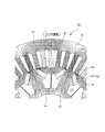
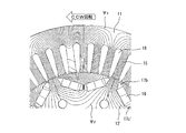
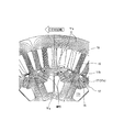
図1において、電動回転機(モータ)10は、概略円筒形状に形成された固定子(ステータ)11と、この固定子11内に回転自在に収納されて軸心に一致する回転駆動軸13が固設されている回転子(ロータ)12と、を備えている。この電動回転機10は、例えば、ハイブリッド自動車(HEV)や電気自動車(EV)において、内燃機関と同様の駆動源として、あるいは車輪ホイール内に搭載するのに好適な性能を有している。
Hereinafter, embodiments of the present invention will be described in detail with reference to the drawings. 1 to 17 are views showing an embodiment of an IPM type electric rotating machine according to the present invention. Here, in the description of the present embodiment, the rotation direction is illustrated by taking as an example a case where the rotor is rotated counterclockwise (CCW) with respect to the stator.
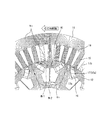
In FIG. 1, an electric rotating machine (motor) 10 includes a stator (stator) 11 formed in a substantially cylindrical shape, and a
固定子11には、回転子12の外周面12aにギャップGを介して内周面15a側を対面させるように軸心の法線方向に延在する複数本のステータティース15が形成されている。このステータティース15には、内部に対面収納されている回転子12を回転駆動させる磁束を発生させるコイルを構成する3相巻線(不図示)が分布巻により巻付形成されている。
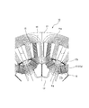
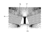
回転子12は、外周面12aに向かって開くV字型になるように、一対で1組の永久磁石16を1磁極として埋め込むIPM(Interior Permanent Magnet)構造になるように作製されている。この回転子12は、図面の表裏方向に延在する平板状の永久磁石16の角部16aを嵌め込んで不動状態に収容するV字空間17が外周面12aに対面するように形成されている。
V字空間17は、永久磁石16を嵌め込み収容する空間17aと、その永久磁石16の幅方向の両側方に位置して磁束の回り込みを制限するフラックスバリアとして機能する空間17b、17c(以下ではフラックスバリア17b、17cともいう)と、を備えるように形成されている。このV字空間17には、永久磁石16を高速回転時の遠心力に抗して位置決め保持することができるように、空間17c間で法線方向に延長されて外周側と内周側とを連結支持するセンタブリッジ20が形成されている。
The
The
The V-shaped
この電動回転機10は、固定子11側のステータティース15間の空間が、巻線を通して巻き掛けることによりコイルを形成するためのスロット18を構成している。これに対して、回転子12は、8組の永久磁石16のそれぞれに、固定子11側の6本のステータティース15が対面している。要するに、この電動回転機10では、回転子12側の一対の永久磁石16側が構成する1磁極に、固定子11側の6スロット18が対応するように構築されている。すなわち、電動回転機10は、隣接する1磁極毎に永久磁石16のN極とS極の表裏を交互にした、8極(4極対)、48スロットで、単相分布巻5ピッチで巻線した3相IPMモータに作製されている。言い換えると、電動回転機10は、毎極毎相スロット数q=(スロット数/極数)/相数=2のIPM型構造に作製されている。
これにより、電動回転機10は、固定子11のスロット18内のコイルに通電してステータティース15から対面する回転子12内に磁束を通すことにより回転駆動させることができる。このとき、電動回転機10(固定子11と回転子12)は、永久磁石16との間に生じる吸引力と反発力に起因するマグネットトルクに加えて、磁束が通過する磁路を最短にしようとするリラクタンストルクとの総合トルクにより回転駆動することができる。よって、電動回転機10は、通電入力する電気的エネルギを、固定子11に対して回転子12と一体回転する回転駆動軸13から、機械的エネルギとして出力することができる。
なお、固定子11と回転子12は、ケイ素鋼などの電磁鋼板材料の薄板を所望の出力トルクに応じた厚さになるように軸方向に重ねており、その積層状態を維持するようにカシメ19などにより一体物に作製されている。
In the electric
Thus, the electric
In addition, the
ここで、この電動回転機10は、図2に磁束線図として図示するように、1磁極を構成する一対の永久磁石16に対応する複数のステータティース15毎に、固定子11の外周側(ステータティース15の背面側)から回転子12内を通過する経路の磁路(電機子磁束)を形成するように、スロット18内に巻線コイルが分布巻きされている。その永久磁石16は、電機子磁束Ψrの磁路に沿うように、言い換えると、その電機子磁束Ψrの形成を妨げないように、形成されているV字空間17の嵌込空間17a内に収容されている。
この永久磁石16の磁路(磁石磁束Ψm)は、図3に磁束線図として図示するように、1磁極を構成する一対の永久磁石16の表裏面のN極とS極から鉛直方向に出て繋げる経路を取り、特に、固定子11側では対応するステータティース15からその背面側を通過する経路になる。
Here, as shown in FIG. 2 as a magnetic flux diagram, the electric
The magnetic path (magnet magnetic flux Ψm) of the
そして、回転子12内に永久磁石16をV字に埋め込んだIPM構造では、磁極が作る磁束の方向、すなわち、V字の永久磁石16間の中心軸をd軸とし、また、そのd軸と電気的・磁気的に直交する、隣接する磁極間の永久磁石16間の中心軸をq軸とする。この回転子12は、V字空間17のd軸側に位置する内側の空間17cを、軸心に向かう大きな空隙に拡大されてフラックスバリア17cとして機能するように形成されている。
これにより、この電動回転機10では、図2に示すように、ステータティース15から回転子12内に進入する電機子磁束Ψrを、V字空間17の外周側に回り込まないように大きく内周(軸心)側に迂回させてステータティース15に戻る経路を取るように形成されている。要するに、電動回転機10は、回転子12がd軸空隙付きV字型IPMモータに構築されている。
また、この電動回転機10は、d軸に対応するステータティース15から進入する電機子磁束Ψrの密度が飽和してしまわないように、回転子12側の外周面に、そのステータティース15の内周面15aと平行方向(軸心方向)に延長されるセンタ溝21が形成されている。
In the IPM structure in which the
As a result, in the electric
Further, the electric
このように、回転子12内に永久磁石16をV字型に埋め込むIPM構造の電動回転機10の場合、トルクTは、下記の式(1)で表すことができ、図4に示すように、マグネットトルクTmとリラクタンストルクTrとの和が最大となる電流位相にて駆動することで高トルク・高効率運転を実現している。

Pp:極対数、Ψm:電機子(ステータティース15)鎖交磁石磁束、
id:線電流のd軸成分、iq:線電流のq軸成分、
Ld:d軸インダクタンス、Lq:q軸インダクタンス
As described above, in the case of the electric
Pp: number of pole pairs, Ψm: armature (stator teeth 15) interlinkage magnet magnetic flux,
id: d-axis component of line current, iq: q-axis component of line current,
Ld: d-axis inductance, Lq: q-axis inductance
ところで、d軸側空隙のフラックスバリア17cに代えて、V字空間17の外側のフラックスバリア17bと同等のフラックスバリア17c´を備える関連技術の回転子12´の場合には、図5Aの磁束線図に図示する永久磁石16の磁路が形成され、その磁石磁束Ψmは、図5Bの磁束ベクトル図に図示する向きのベクトルVmになっている。また、スロット18への通電により発生する電機子磁束Ψrは、図6Aの磁束線図に図示する磁路に形成され、図6Bの磁束ベクトル図に図示する向きのベクトルVrになっている。
この種の電動回転機では、最大負荷駆動時には高トルク・高効率駆動の実現のために電流位相角を進角させて駆動させている。関連技術の回転子12´では、図5Bおよび図6Bの磁束ベクトル図に示すように、V字空間17(磁極)の外周側に位置するd軸付近の小領域A1において、磁石磁束Ψmと電機子磁束Ψrが逆磁界の関係になって、リラクタンストルクTrがマグネットトルクTmを打ち消し(相殺し)つつ駆動する状態にある。要するに、この磁極外周側小領域A1は、図7に示すように、磁石磁束Ψmと電機子磁束Ψrとが挟角90度以上で逆向きの位置関係で対向する干渉領域であり、この磁極外周側小領域A1に隣接する永久磁石16のd軸側の範囲Bで発生する磁石磁束Ψmを抑え込む(打ち消す)のに電機子磁束Ψrが浪費されている。
このことから、この磁極外周側小領域A1に対応する永久磁石16のd軸側範囲Bは、トルクTに積極的に寄与していないと言うことができ、その永久磁石16におけるd軸側範囲Bの部分を削減しつつ同等の突極比を維持する磁気回路とすることで、永久磁石16自体の磁石量を低減することができる。
ここで、トルクTは、上記式(1)であるため、永久磁石16の磁石量を減らした場合にはリラクタンストルクTrを大きくすることで、永久磁石16の磁石量を減らさない場合と同等にすることができる。このリラクタンストルクTrは、d軸インダクタンスLdとq軸インダクタンスLqとの差、すなわち、突極比を大きくすることで増加させることができる。
よって、本実施形態の回転子12では、永久磁石16のd軸側範囲Bを透磁率の小さな空隙(制限領域)に置き換えることで、永久磁石16の磁石量を低減しつつ突極比を増加させて置換前と同等以上のトルクTを得ることができる。見方を換えると、リラクタンストルクTrは、永久磁石16のd軸側範囲Bで発生する磁石磁束Ψmを抑え込むのに浪費されていた電機子磁束Ψrを有効活用することで大きくすることができ、永久磁石16の磁石量を削減しても同等のトルクTを得ることができる。
By the way, in the case of the
In this type of electric rotating machine, at the time of maximum load driving, the current phase angle is advanced to achieve high torque and high efficiency driving. In the related art rotor 12 ', as shown in the magnetic flux vector diagrams of FIGS. 5B and 6B, in the small region A1 near the d-axis located on the outer peripheral side of the V-shaped space 17 (magnetic pole), the magnetic flux Ψm and the electric machine The reluctance torque Tr is driven while canceling (cancelling) the magnet torque Tm because the child magnetic flux Ψr has a reverse magnetic field relationship. In short, as shown in FIG. 7, the magnetic pole outer peripheral side small area A1 is an interference area where the magnet magnetic flux Ψm and the armature magnetic flux Ψr face each other in a reverse positional relationship at an included angle of 90 degrees or more. The armature magnetic flux Ψr is wasted to suppress (cancel) the magnetic flux Ψm generated in the range B on the d-axis side of the
From this, it can be said that the d-axis side range B of the
Here, since the torque T is expressed by the above equation (1), when the magnet amount of the
Therefore, in the
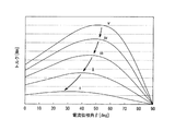
なお、トルクTは、下記の式(2)のように表すこともでき、電流値Iaが小さな低負荷領域ではマグネットトルクTmの割合が高くなり、図8に示すように、電流値Iaが低いほど最大トルク時の電流位相βはゼロに近くなる。この図8中の波形i〜vは、各電流値Ia(i)〜Ia(v)における電流位相−トルク特性を示しており、電流値Iaの大きさは、i<ii<iii<iv<vの関係となっている。よって、低負荷駆動時には、マグネットトルクTmの割合(依存)が自ずと高くなるが、そのマグネットトルクTmを最大限に有効活用する磁気回路が望ましい。
β:電流位相角度、Ia:相電流値
The torque T can also be expressed as in the following formula (2). In the low load region where the current value Ia is small, the ratio of the magnet torque Tm is high, and the current value Ia is low as shown in FIG. The current phase β at the maximum torque becomes closer to zero. Waveforms i to v in FIG. 8 indicate current phase-torque characteristics at the respective current values Ia (i) to Ia (v), and the magnitude of the current value Ia is i <ii <iii <iv <iv <. The relationship is v. Therefore, the ratio (dependence) of the magnet torque Tm naturally increases during low-load driving, but a magnetic circuit that effectively uses the magnet torque Tm to the maximum is desirable.
β: current phase angle, Ia: phase current value
関連技術の回転子12´では、図9に示すように、低電流値の低負荷領域では電流位相βがゼロに近い条件で駆動させるため、電機子磁束Ψrの磁束量がq軸となる磁極間(隣接する別磁極の永久磁石16の間)で多くなる。このため、この電機子磁束Ψrに磁石磁束Ψmを合成した磁束Ψsの経路としては、図10に示す磁路MP1、MP2を通過する磁気回路とするのが好適である。これにより、合成磁束Ψsは、q軸磁路(磁束)を分散化させて(飽和することを回避して)q軸インダクタンスLqを大きくすることができ、リラクタンストルクTrを積極的に利用可能にすることができる。
磁路MP1は、固定子11側のステータティース15からエアギャップGを介して回転子12´に鎖交して磁極間に進入した後に、回転方向進行側(図中左側)の磁極を形成する近接側の永久磁石16を内周側から抜ける経路を取る。さらに、この磁路MP1は、その磁極の外周側領域A2を通過して、再度エアギャップGを介してステータティース15に戻る経路を取る。
磁路MP2は、磁路MP1と同様に磁極間に進入した後に、回転方向進行側の磁極を形成する離隔側の永久磁石16を内周側から抜けて、その磁極の外周側領域A2を通過して、再度エアギャップGを介してステータティース15に戻る経路を取る。
In the related art rotor 12 ', as shown in FIG. 9, in the low load region with a low current value, the current phase β is driven under a condition close to zero, so the magnetic flux amount of the armature magnetic flux Ψr is q-axis. (Between adjacent
The magnetic path MP1 forms a magnetic pole on the traveling side in the rotation direction (left side in the figure) after interlinking from the
The magnetic path MP2 enters between the magnetic poles in the same manner as the magnetic path MP1, and then passes through the outer peripheral side area A2 of the magnetic pole through the separation-side
例えば、この磁路MP1、MP2では、一対の永久磁石16の両端側(磁極外端部)を削って内側に寄せた場合には、その両端側に大きなフラックスバリアが存在して磁極の中心付近に集中することになり、特に、磁極外周側領域A2の右側の経路が取り難くなって、その領域A2全体を有効に利用できない。
反対に、一対の永久磁石16の中心側(磁極内端部)を削って外側に寄せた場合には、その中心側に大きなフラックスバリアが存在して磁極の両側に磁束経路を分散させることができ、磁極外周側領域A2の右側の経路も含めて積極的に有効活用してその領域A2を満遍なく磁束が通過できる。この構造の場合には、回転方向後進側の磁極の永久磁石16を外周側から内周側に向かって抜けた後、隣接する磁極の永久磁石16のN極・S極間を結合する磁路MP3も取ることができる。この磁路MP3では、磁路MP1と同様の経路を通って、回転方向進行側の磁極の外周側領域A2を通過することができ、磁束の分散化効率が高い。
このことから、回転子12は、磁極を形成する一対の永久磁石16の埋設構造として、リラクタンストルクTrを発生させる電機子磁束Ψrを妨げないようにV字型を維持しつつ、両端側(磁極外端部)に寄せる形状を採用するのが好適である。さらに、その一対の永久磁石16の間(磁極内端部)には、磁束が短絡経路を取るのを制限するフラックスバリア17cを形成する構造を採用するのが好適である。また、回転子12のd軸上の外周面には、固定子11側のステータティース15から進入する電機子磁束Ψrの飽和を制限する、言い換えると、その磁束Ψrを分散させるセンタ溝21を形成する構造を採用するのが好適である。このような構造を採用することにより、回転子12は、q軸磁路(磁束)を分散化させてq軸インダクタンスLqを大きくし、リラクタンストルクTrを積極的に利用することができる。
For example, in the magnetic paths MP1 and MP2, when both end sides (magnetic pole outer end portions) of the pair of
On the other hand, when the center side (the inner end of the magnetic pole) of the pair of
Therefore, the
この永久磁石16は、図面内の長手方向の長さ(幅)Wpmの最適値を、その長さWpmを短縮しない場合を基準にして比較決定する。
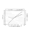
具体的には、極数Pと、回転子12の軸心から外周面までの外半径Rとを固定値として、磁極外端部に設置する永久磁石16の長さWpmを変数(内端側端辺の位置を変位)とし、下記の式(3)で算出する比率δを変化させて決定する。この決定要素として、比率δに対する、最大負荷時のトルクTのper unit単位での変化と、そのトルクTの変動幅であるトルクリプル(torque ripple)の低減率の変化とを磁界解析してグラフ表示すると、図11のようになる。なお、per unit単位では、例えば、1.0[p.u.]の場合に同等であることを意味している。
δ=(P×Wpm)/R ・・・(3)
図11では、比率δ=1.84が長さWpmを短縮しない形状寸法(磁石低減量0%)の永久磁石16の場合であり、比率δ=1.38の寸法形状(磁石低減量24.7%)の場合に非短縮時と同等(1.0[p.u.])のトルクTを得ることができることが分かる。この永久磁石16は、常用の低速回転負荷時においても、比率δ=1.38とすることで、同等のトルクTを得ることができる。
ここで、この図11では、V字空間17の内外端側に同等の大きさのフラックスバリア17b、17c´を備える関連技術の回転子12´を比較対象としている。これに対して、本実施形態の回転子12の場合には、フラックスバリア17cとセンタ溝21を備えることで、電機子磁束Ψrを効果的に分割して振り分けることができる。このため、この回転子12では、リラクタンストルクTrを有効に発生させることができ、永久磁石16が同等の長さWpmである比率δ=1.84でもトルクTが向上するとともにトルクリプルも低減されている。すなわち、図11では、この回転子12の構造で永久磁石16の長さWpmを短縮させて、比率δに対するトルクTとトルクリプルの変化を図示している。なお、関連技術の回転子12´の構造のまま永久磁石16の長さWpmを短縮する場合には、比率δ=1.84から比率δ=1.38付近までトルクTの大きな変化はない(1.0[p.u.])ものと想定される。
The
Specifically, with the number of poles P and the outer radius R from the axis of the
δ = (P × Wpm) / R (3)
In FIG. 11, the ratio δ = 1.84 is the case of the
Here, in FIG. 11, a
また、電動回転機では、回転子の回転に伴って、埋設する永久磁石量に応じた誘起電圧(逆起電圧)が発生して弱め界磁に起因する磁気歪みの空間高調波が重畳することになる。この空間高調波は、5次、7次、11次、13次の成分がトルクリプルの発生要因になり、鉄損の増加原因となっている。このことから、比率δに対する、例えば、5次の空間高調波の発生をper unit単位でグラフ化すると、図12のようになり、比率δ=1.75以下にするほど、その5次の空間高調波の発生を抑えることができることが分かる。この場合には、永久磁石16の磁石量を4.7%以上削減することができ、また、磁気歪みの空間高調波の低減により鉄損を低減して駆動効率を向上させつつ永久磁石16内での渦電流の発生を制限して発熱を抑えることができる。
Moreover, in the electric rotating machine, an induced voltage (counterelectromotive voltage) corresponding to the amount of the permanent magnet to be embedded is generated with the rotation of the rotor, and spatial harmonics of magnetostriction caused by the field weakening are superimposed. become. In this spatial harmonic, the fifth, seventh, eleventh, and thirteenth components cause torque ripple and cause an increase in iron loss. From this, for example, when the generation of fifth-order spatial harmonics with respect to the ratio δ is graphed in units of per unit, the result is as shown in FIG. 12, and the fifth-order space becomes smaller as the ratio δ = 1.75 or less. It can be seen that the generation of harmonics can be suppressed. In this case, the magnet amount of the
このことからすると、本実施形態の回転子12では、関連技術の回転子12´と同等のトルクTを得つつ永久磁石16の使用量を削減するには、その永久磁石16の長さWpmを短縮(磁石量を24.7%削減)して比率δ=1.38程度にするのが好適であり、トルクリプルも低減することができる。要するに、永久磁石16は、トルクTやトルクリプル等の所望の特性に応じて比率δ=1.38(磁石低減量24.7%)から1.75(磁石低減量4.7%)の範囲内の寸法形状で適宜選択すればよい。
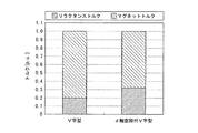
そこで、電動回転機10は、同等のトルクTとなる、永久磁石16の長さWpmを短縮して比率δ=1.38の寸法形状に形成するd軸空隙付きV字型のIPMモータの場合と、永久磁石16を短縮しないV字型のIPMモータの場合とで磁界解析すると、図13および図14に示すように、マグネットトルクTmとリラクタンストルクTrの比率が変化して同等のトルクTを出力可能なことが分かる。なお、d軸空隙付きV字型のIPMモータは、大きな空隙のフラックスバリア17cをd軸側に備える構造であり、単なるV字型のIPMモータは、小さなフラックスバリア17c´をd軸側に備える構造である。
この図13は、低負荷領域でのトルクTm、Trの割合を図示しており、図14は、最大負荷領域でのトルクTm、Trの割合を図示している。いずれでも、d軸空隙付きV字型のIPMモータの場合には、永久磁石16を短縮するためにマグネットトルクTmが小さくなるのに代わって、リラクタンストルクTrが大きくなっていることが分かる。すなわち、電動回転機10は、d軸付近の永久磁石16に置換して大きな空隙空間のフラックスバリア17cやセンタ溝21を形成することで、図6Bと図7に示す磁極外周側小領域A1で電機子磁束Ψrを打ち消す磁石磁束Ψmを少なくすることができている。この結果、電動回転機10は、q軸インダクタンスLqを大きくしてd軸インダクタンスLdとの差(突極比)を非短縮V字型のIPMモータよりも大きくすることができ、リラクタンストルクTrを有効活用して同等のトルクTを確保することができている。
From this, in the
Therefore, the electric
FIG. 13 illustrates the ratios of torques Tm and Tr in the low load region, and FIG. 14 illustrates the ratios of torques Tm and Tr in the maximum load region. In any case, in the case of a V-shaped IPM motor with a d-axis gap, it can be seen that the reluctance torque Tr is increased instead of decreasing the magnet torque Tm in order to shorten the
この構造により、電動回転機10は、図15に磁束線図として図示するように、磁極を形成する一対の永久磁石16の外周側の小領域A1に集中していた電機子磁束Ψrを、その磁極外周側小領域A1を通過する磁路Mr1からV字空間17のd軸側空間17cの内周側を迂回する磁路Mr2にも効果的に分割(分流)させることができる。この結果、電動回転機10は、磁石磁束Ψmと電機子磁束Ψr(d軸・q軸)の磁気的干渉を低減して、磁極外周側小領域A1の回転方向進行側(図中左側)で局所的に磁気飽和状態になってしまうことを回避してトルクTの発生に効果的に寄与させることができる。
With this structure, as shown in FIG. 15 as a magnetic flux diagram, the electric
したがって、電動回転機10は、図16の磁束線図に図示するように、低負荷駆動時には磁石磁束Ψmと電機子磁束Ψrの合成磁束Ψsが主に永久磁石16を通過する磁路MP0を通過するのに対して、最大負荷駆動時にはその合成磁束Ψsは図17の磁束線図に図示するように、磁路MP1、磁路MP2に分割させることができる。この結果、磁気的干渉の低減と共に局所的な磁気飽和状態の回避を実現して、永久磁石16の磁石量を低減しつつ同等以上のトルクTを効率よく発生させることができる。なお、低負荷駆動時の合成磁束Ψsは、電機子磁束Ψrよりも磁石磁束Ψmの割合が大きい。
また、電動回転機10は、永久磁石16を、例えば、比率δ=1.44の寸法形状にして低透磁率のフラックスバリア17cに置換(磁石磁束Ψmを低減)し磁石量を23%削減すると、イナーシャ(慣性力)の低減と共に、誘起電圧定数も13.4%程度低減することができ、高速回転側での出力を増加させることができる。さらに、この電動回転機10では、磁気歪みとなる空間高調波が低減されることで、永久磁石16内で発生する渦電流による発熱や鉄損および電磁騒音を抑えることができる。
Therefore, as shown in the magnetic flux diagram of FIG. 16, the electric
Further, the electric
このように本実施形態においては、永久磁石16のd軸側範囲Bを削減して大きなフラックスバリア17cに置き換えたので、電機子磁束Ψrを打ち消す方向の磁石磁束Ψmをなくして互いに干渉(相殺)してしまうことをなくすことができ、また、その範囲B内を電機子磁束Ψrが通過してしまうことも制限することができる。
したがって、永久磁石16の使用量を削減しつつ、d軸側での電機子磁束Ψrや磁石磁束Ψmを有効に活用して、大きなマグネットトルクTmとリラクタンストルクTrを得ることができる。また、誘起電圧定数の低減による高速回転側での出力の増加を図ることができるとともに、永久磁石16の渦電流に起因する発熱を抑えて温度変化による減磁を抑制して耐熱グレードを下げることによるコスト削減をすることができる。
この結果、固定子11内の回転子12を低コストに作製して高エネルギ密度で高品質に回転駆動させることができる。
As described above, in the present embodiment, the d-axis side range B of the
Therefore, a large magnet torque Tm and a reluctance torque Tr can be obtained by effectively using the armature magnetic flux Ψr and the magnet magnetic flux Ψm on the d-axis side while reducing the amount of
As a result, the
ここで、本実施形態では、8極48スロットモータの構成の電動回転機10を一例にして説明するが、これに限るものではなく、毎極毎相スロット数q=2の構造であれば、そのまま好適に適用することができ、例えば、6極36スロット、4極24スロット、10極60スロットのモータ構造にもそのまま適用することができる。
本発明の範囲は、図示され記載された例示的な実施形態に限定されるものではなく、本発明が目的とするものと均等な効果をもたらすすべての実施形態をも含む。さらに、本発明の範囲は、各請求項により画される発明の特徴の組み合わせに限定されるものではなく、すべての開示されたそれぞれの特徴のうち特定の特徴のあらゆる所望する組み合わせによって画されうる。
Here, in this embodiment, the electric
The scope of the present invention is not limited to the illustrated and described exemplary embodiments, but includes all embodiments that provide the same effects as those intended by the present invention. Further, the scope of the invention is not limited to the combinations of features of the invention defined by the claims, but may be defined by any desired combination of particular features among all the disclosed features. .
これまで本発明の一実施形態について説明したが、本発明は上述の実施形態に限定されず、その技術的思想の範囲内において種々異なる形態にて実施されてよいことは言うまでもない。 Although one embodiment of the present invention has been described so far, it is needless to say that the present invention is not limited to the above-described embodiment, and may be implemented in various forms within the scope of the technical idea.
10 電動回転機(IPM型)
11 固定子
12 回転子
12a 外周面
13 回転駆動軸
15 ステータティース
16 永久磁石
16a 角部
17 V字空間
17b、17c フラックスバリア
18 スロット
20 センタブリッジ
21 センタ溝
A1 磁極外周側小領域
A2 磁極外周側領域
B d軸側範囲
G エアギャップ
MP0、MP1〜MP3、Mr1、Mr2 磁路
Ψm 磁石磁束
Ψr 電機子磁束
Ψs 合成磁束
10 Electric rotating machine (IPM type)
11
Claims (2)
前記永久磁石が形成する磁極毎の該永久磁石の中心軸に一致する磁束方向のd軸側まで当該永久磁石を存在させた場合に、該d軸側において前記電機子が発生する電機子磁束を打ち消す方向の磁石磁束を発生する範囲の前記永久磁石を、透磁率の小さな空隙に置き換えたことを特徴とするIPM型電動回転機。 An IPM comprising: a rotor in which a permanent magnet is embedded; and a stator that functions as an armature by accommodating the rotor so as to be relatively rotatable and accommodating a coil in a slot between a plurality of teeth facing the rotor. Type electric rotating machine,
The armature magnetic flux generated by the armature on the d-axis side when the permanent magnet exists up to the d-axis side in the magnetic flux direction coinciding with the central axis of the permanent magnet for each magnetic pole formed by the permanent magnet. An IPM type electric rotating machine characterized in that the permanent magnet in a range in which a magnetic flux in the direction of cancellation is generated is replaced with a gap having a small magnetic permeability.
前記回転子の半径方向の前記永久磁石の大きさをWpm、前記回転子の外周面までの半径をR、前記永久磁石が形成する磁極数をPとしたとき、
1.38≦(P×Wpm)/R<1.84
を満たすことを特徴とする請求項1に記載のIPM型電動回転機。 In the case of a structure with the number of slots per phase per phase q = 2,
When the size of the permanent magnet in the radial direction of the rotor is Wpm, the radius to the outer peripheral surface of the rotor is R, and the number of magnetic poles formed by the permanent magnet is P,
1.38 ≦ (P × Wpm) / R <1.84
The IPM type electric rotating machine according to claim 1, wherein:
Priority Applications (16)
| Application Number | Priority Date | Filing Date | Title |
|---|---|---|---|
| JP2012217463A JP2014072995A (en) | 2012-09-28 | 2012-09-28 | Ipm type electric rotary machine |
| US14/031,226 US20140091664A1 (en) | 2012-09-28 | 2013-09-19 | Interior permanent magnet electric rotating machine |
| DE102013219067.0A DE102013219067B4 (en) | 2012-09-28 | 2013-09-23 | ELECTRIC LATHE WITH INSIDE PERMANENT MAGNETS |
| DE102013219022.0A DE102013219022B4 (en) | 2012-09-28 | 2013-09-23 | Electric lathe with permanent magnets inside |
| DE102013219058.1A DE102013219058B4 (en) | 2012-09-28 | 2013-09-23 | ELECTRIC LATHE WITH INSIDE PERMANENT MAGNETS |
| DE102013219020.4A DE102013219020B4 (en) | 2012-09-28 | 2013-09-23 | Electric lathe with permanent magnets inside |
| DE102013219106.5A DE102013219106B4 (en) | 2012-09-28 | 2013-09-24 | ELECTRIC LATHE WITH INSIDE PERMANENT MAGNETS |
| DE102013219260.6A DE102013219260B4 (en) | 2012-09-28 | 2013-09-25 | Electric lathe with permanent magnets inside |
| DE102013219222.3A DE102013219222B4 (en) | 2012-09-28 | 2013-09-25 | Electric lathe with permanent magnets inside |
| CN201310451355.8A CN103715851B (en) | 2012-09-28 | 2013-09-27 | IPM type turning motor |
| CN201310449982.8A CN103715797B (en) | 2012-09-28 | 2013-09-27 | IPM rotary motor |
| CN201310451713.5A CN103715800B (en) | 2012-09-28 | 2013-09-27 | IPM rotary motor |
| CN201310451292.6A CN103715798B (en) | 2012-09-28 | 2013-09-27 | IPM rotary motor |
| CN201310451587.3A CN103715799B (en) | 2012-09-28 | 2013-09-27 | IPM rotary motor |
| CN201310451855.1A CN103715801B (en) | 2012-09-28 | 2013-09-27 | IPM rotary motor |
| CN201310451456.5A CN103715852B (en) | 2012-09-28 | 2013-09-27 | IPM rotary motor |
Applications Claiming Priority (1)
| Application Number | Priority Date | Filing Date | Title |
|---|---|---|---|
| JP2012217463A JP2014072995A (en) | 2012-09-28 | 2012-09-28 | Ipm type electric rotary machine |
Publications (1)
| Publication Number | Publication Date |
|---|---|
| JP2014072995A true JP2014072995A (en) | 2014-04-21 |
Family
ID=50276481
Family Applications (1)
| Application Number | Title | Priority Date | Filing Date |
|---|---|---|---|
| JP2012217463A Pending JP2014072995A (en) | 2012-09-28 | 2012-09-28 | Ipm type electric rotary machine |
Country Status (4)
| Country | Link |
|---|---|
| US (1) | US20140091664A1 (en) |
| JP (1) | JP2014072995A (en) |
| CN (1) | CN103715801B (en) |
| DE (1) | DE102013219020B4 (en) |
Cited By (2)
| Publication number | Priority date | Publication date | Assignee | Title |
|---|---|---|---|---|
| JP2017139864A (en) * | 2016-02-02 | 2017-08-10 | 株式会社デンソー | Rotary electric machine |
| JP2020137139A (en) * | 2019-02-12 | 2020-08-31 | トヨタ自動車株式会社 | Rotary electric machine |
Families Citing this family (22)
| Publication number | Priority date | Publication date | Assignee | Title |
|---|---|---|---|---|
| EP2680401B1 (en) * | 2012-06-29 | 2020-09-02 | GE Renewable Technologies Wind B.V. | Permanent magnet rotor |
| FR3002091B1 (en) * | 2013-02-14 | 2016-07-15 | Moteurs Leroy-Somer | ROTATING ELECTRIC MACHINE. |
| WO2015045069A1 (en) * | 2013-09-26 | 2015-04-02 | 三菱電機株式会社 | Permanent magnet embedded electric motor, compressor, and refrigerating and air-conditioning device |
| JP5962632B2 (en) * | 2013-11-15 | 2016-08-03 | 株式会社デンソー | Rotor for rotating electrical machine and method for manufacturing the same |
| JP6226196B2 (en) * | 2014-04-15 | 2017-11-08 | 株式会社デンソー | Rotating electrical machine rotor |
| EP3457546B1 (en) | 2016-05-10 | 2021-04-28 | Mitsubishi Electric Corporation | Permanent magnet motor |
| US10293804B2 (en) | 2016-05-19 | 2019-05-21 | GM Global Technology Operations LLC | Hybrid vehicle engine starter systems and methods |
| US10184442B2 (en) | 2016-05-19 | 2019-01-22 | GM Global Technology Operations LLC | Permanent magnet electric machine |
| US10505415B2 (en) | 2016-05-19 | 2019-12-10 | GM Global Technology Operations LLC | Permanent magnet electric machine |
| DE102016209711A1 (en) | 2016-06-02 | 2018-01-04 | Volkswagen Aktiengesellschaft | rotor core |
| DE102016209709A1 (en) | 2016-06-02 | 2017-12-21 | Volkswagen Aktiengesellschaft | rotor core |
| US10523072B2 (en) | 2016-06-15 | 2019-12-31 | Ford Global Technologies, Llc | Electric machine rotor |
| JP2018061392A (en) * | 2016-10-07 | 2018-04-12 | 株式会社デンソー | Armature and rotary electric machine |
| US10605217B2 (en) | 2017-03-07 | 2020-03-31 | GM Global Technology Operations LLC | Vehicle engine starter control systems and methods |
| US10608487B2 (en) * | 2017-03-07 | 2020-03-31 | Ford Global Technologies, Llc | Electric machine rotor |
| US10355537B2 (en) | 2017-03-27 | 2019-07-16 | Ford Global Technologies, Llc | Method for adjusting magnetic permeability of electrical steel |
| TWM576750U (en) | 2017-07-25 | 2019-04-11 | 美商米沃奇電子工具公司 | Electrical composition, electric device system, battery pack, electric motor, motor assembly and electric motor assembly |
| US10879775B2 (en) * | 2018-05-23 | 2020-12-29 | Ford Global Technologies, Llc | Surface treatments of electrical steel core devices |
| DE102018123706A1 (en) * | 2018-09-26 | 2020-03-26 | Dr. Ing. H.C. F. Porsche Aktiengesellschaft | Rotor for a synchronous machine |
| DE102018132502A1 (en) * | 2018-12-17 | 2020-06-18 | Valeo Siemens Eautomotive Germany Gmbh | Rotor plate, rotor and electrical machine and method for producing a rotor |
| US11780061B2 (en) | 2019-02-18 | 2023-10-10 | Milwaukee Electric Tool Corporation | Impact tool |
| DE102019206088A1 (en) * | 2019-04-29 | 2020-10-29 | Volkswagen Aktiengesellschaft | Rotor sheet metal, in particular sheet metal cut, for a rotor of an electrical machine and electrical machine |
Family Cites Families (21)
| Publication number | Priority date | Publication date | Assignee | Title |
|---|---|---|---|---|
| US4486679A (en) * | 1983-10-28 | 1984-12-04 | General Electric Company | Permanent magnet rotor and method of making same |
| MY155225A (en) | 1995-05-31 | 2015-09-30 | Panasonic Corp | Motor with built-in permanent magnets |
| JP4363746B2 (en) * | 2000-05-25 | 2009-11-11 | 株式会社東芝 | Permanent magnet type reluctance type rotating electrical machine |
| JP3708855B2 (en) | 2000-09-13 | 2005-10-19 | 山洋電気株式会社 | Synchronous motor with built-in permanent magnet |
| JP4490047B2 (en) | 2003-04-28 | 2010-06-23 | トヨタ自動車株式会社 | Electric motor |
| JP4311182B2 (en) | 2003-12-08 | 2009-08-12 | 日産自動車株式会社 | Rotating electric machine rotor |
| JP4449035B2 (en) * | 2004-03-10 | 2010-04-14 | 日立オートモティブシステムズ株式会社 | Permanent magnet rotating electric machine for electric vehicles |
| JP2006254629A (en) | 2005-03-11 | 2006-09-21 | Toyota Motor Corp | Rotor of rotating electric machine, rotating electric machine, and vehicle driving apparatus |
| US20080258573A1 (en) | 2005-03-11 | 2008-10-23 | Toyota Jidosha Kabushiki Kaisha | Rotor of Rotating Electric Machine, Rotating Electric Machine and Vehicle Drive Apparatus |
| CN101283499A (en) * | 2005-08-31 | 2008-10-08 | 株式会社东芝 | Rotary electric machine |
| JP4815967B2 (en) * | 2005-09-21 | 2011-11-16 | トヨタ自動車株式会社 | Permanent magnet rotating electric machine |
| JP4898201B2 (en) * | 2005-12-01 | 2012-03-14 | アイチエレック株式会社 | Permanent magnet rotating machine |
| JP5288698B2 (en) | 2006-10-20 | 2013-09-11 | 株式会社東芝 | Permanent magnet type reluctance type rotating electrical machine |
| JP4492681B2 (en) * | 2007-11-16 | 2010-06-30 | 株式会社デンソー | Synchronous machine |
| JP5238231B2 (en) * | 2007-11-28 | 2013-07-17 | 株式会社東芝 | Rotating electrical machine rotor |
| US9431860B2 (en) | 2009-12-22 | 2016-08-30 | Toyota Jidosha Kabushiki Kaisha | Rotor and method of manufacturing rotor |
| JP5479978B2 (en) * | 2010-03-30 | 2014-04-23 | アイシン・エィ・ダブリュ株式会社 | Rotating electric machine |
| JP5708181B2 (en) * | 2010-05-12 | 2015-04-30 | 株式会社デンソー | Rotating electrical machine rotor |
| JP5482544B2 (en) | 2010-07-28 | 2014-05-07 | トヨタ自動車株式会社 | Rotating electric machine |
| JP5480176B2 (en) * | 2011-02-03 | 2014-04-23 | アイシン・エィ・ダブリュ株式会社 | Rotating machine rotor |
| JP5768240B2 (en) | 2011-04-04 | 2015-08-26 | 株式会社ソフイア | Game machine |
-
2012
- 2012-09-28 JP JP2012217463A patent/JP2014072995A/en active Pending
-
2013
- 2013-09-19 US US14/031,226 patent/US20140091664A1/en not_active Abandoned
- 2013-09-23 DE DE102013219020.4A patent/DE102013219020B4/en active Active
- 2013-09-27 CN CN201310451855.1A patent/CN103715801B/en active Active
Cited By (4)
| Publication number | Priority date | Publication date | Assignee | Title |
|---|---|---|---|---|
| JP2017139864A (en) * | 2016-02-02 | 2017-08-10 | 株式会社デンソー | Rotary electric machine |
| US10424981B2 (en) | 2016-02-02 | 2019-09-24 | Denso Corporation | Rotating electric machine with magnetic gaps |
| JP2020137139A (en) * | 2019-02-12 | 2020-08-31 | トヨタ自動車株式会社 | Rotary electric machine |
| JP7107243B2 (en) | 2019-02-12 | 2022-07-27 | トヨタ自動車株式会社 | Rotating electric machine |
Also Published As
| Publication number | Publication date |
|---|---|
| DE102013219020A1 (en) | 2014-04-03 |
| CN103715801B (en) | 2016-03-09 |
| DE102013219020B4 (en) | 2020-08-06 |
| CN103715801A (en) | 2014-04-09 |
| US20140091664A1 (en) | 2014-04-03 |
Similar Documents
| Publication | Publication Date | Title |
|---|---|---|
| JP2014072995A (en) | Ipm type electric rotary machine | |
| CN104185938B (en) | Motor | |
| JP5479978B2 (en) | Rotating electric machine | |
| EP3457534B1 (en) | Rotating electric machine | |
| EP3534496B1 (en) | Permanent magnet motor | |
| WO2014155438A1 (en) | Permanent magnet reluctance dynamo-electric machine | |
| JP5958305B2 (en) | IPM type electric rotating machine | |
| JP2009219331A (en) | Permanent magnet type generator and hybrid vehicle using the same | |
| CN108336837A (en) | A kind of composite excitation direct driving motor | |
| JP5450472B2 (en) | Permanent magnet generator and hybrid vehicle using it | |
| JPWO2019050050A1 (en) | Rotor and rotating electric machine | |
| Wang et al. | Design of new dual-stator field modulation machines | |
| JP5323592B2 (en) | Permanent magnet rotating electric machine and electric vehicle using the same | |
| JP6070032B2 (en) | IPM type electric rotating machine | |
| JP6015350B2 (en) | IPM type electric rotating machine | |
| JP6437706B2 (en) | IPM type electric rotating machine | |
| JP6592525B2 (en) | Magnet rotor, rotating electric machine including magnet rotor, and electric vehicle including rotating electric machine | |
| JP6760014B2 (en) | Rotating electric machine | |
| JP2018061379A (en) | Dynamo-electric machine | |
| Zhang et al. | A permanent magnet traction machine with wide high efficiency range for EV application | |
| JP6711082B2 (en) | Rotating electric machine | |
| KR20220044429A (en) | Electric motor having stacked different rotor segments and method for designing the same | |
| JP6075034B2 (en) | IPM type electric rotating machine | |
| JP5612632B2 (en) | Permanent magnet rotating electric machine | |
| JP6015331B2 (en) | IPM type electric rotating machine |