JP5762804B2 - Mask manufacturing method, mask - Google Patents
Mask manufacturing method, mask Download PDFInfo
- Publication number
- JP5762804B2 JP5762804B2 JP2011086758A JP2011086758A JP5762804B2 JP 5762804 B2 JP5762804 B2 JP 5762804B2 JP 2011086758 A JP2011086758 A JP 2011086758A JP 2011086758 A JP2011086758 A JP 2011086758A JP 5762804 B2 JP5762804 B2 JP 5762804B2
- Authority
- JP
- Japan
- Prior art keywords
- mask
- main body
- ear
- extension direction
- mask main
- Prior art date
- Legal status (The legal status is an assumption and is not a legal conclusion. Google has not performed a legal analysis and makes no representation as to the accuracy of the status listed.)
- Active
Links
Images


Classifications
-
- A—HUMAN NECESSITIES
- A62—LIFE-SAVING; FIRE-FIGHTING
- A62B—DEVICES, APPARATUS OR METHODS FOR LIFE-SAVING
- A62B18/00—Breathing masks or helmets, e.g. affording protection against chemical agents or for use at high altitudes or incorporating a pump or compressor for reducing the inhalation effort
- A62B18/08—Component parts for gas-masks or gas-helmets, e.g. windows, straps, speech transmitters, signal-devices
-
- A—HUMAN NECESSITIES
- A62—LIFE-SAVING; FIRE-FIGHTING
- A62B—DEVICES, APPARATUS OR METHODS FOR LIFE-SAVING
- A62B23/00—Filters for breathing-protection purposes
- A62B23/02—Filters for breathing-protection purposes for respirators
- A62B23/025—Filters for breathing-protection purposes for respirators the filter having substantially the shape of a mask
-
- A—HUMAN NECESSITIES
- A62—LIFE-SAVING; FIRE-FIGHTING
- A62B—DEVICES, APPARATUS OR METHODS FOR LIFE-SAVING
- A62B18/00—Breathing masks or helmets, e.g. affording protection against chemical agents or for use at high altitudes or incorporating a pump or compressor for reducing the inhalation effort
- A62B18/02—Masks
-
- A—HUMAN NECESSITIES
- A41—WEARING APPAREL
- A41D—OUTERWEAR; PROTECTIVE GARMENTS; ACCESSORIES
- A41D13/00—Professional, industrial or sporting protective garments, e.g. surgeons' gowns or garments protecting against blows or punches
- A41D13/05—Professional, industrial or sporting protective garments, e.g. surgeons' gowns or garments protecting against blows or punches protecting only a particular body part
- A41D13/11—Protective face masks, e.g. for surgical use, or for use in foul atmospheres
- A41D13/1107—Protective face masks, e.g. for surgical use, or for use in foul atmospheres characterised by their shape
- A41D13/1115—Protective face masks, e.g. for surgical use, or for use in foul atmospheres characterised by their shape with a horizontal pleated pocket
Description
本発明は、マスク着用者の顔に装着されるマスクに関するものである。 The present invention relates to a mask worn on the face of a mask wearer.
従来、例えば下記特許文献1には、マスク着用者の顔に装着されるマスクの製造方法が開示されている。この製造方法では、概してマスク着用者の顔面を覆うマスク本体部と、当該マスク着用者の耳に引っ掛けられる耳掛け部とをそれぞれ連続して搬送する一方、マスク本体部と耳掛け部を互いに接合することによって複数のマスクが連続的に製造される。ところで、この種のマスクでは、マスク本体部や耳掛け部が相対的に伸長し易い方向があり、これによりマスク製造時の搬送の際、マスク本体部や耳掛け部の変形、歪み、位置ずれ等が生じる不具合が想定される。そこで、この種のマスクの設計に際しては、マスク製造時の取り扱いを容易にするべく、マスク本体部や耳掛け部の伸張方向を考慮した上でマスクや当該マスクの製造方法を構築することが要請される。 Conventionally, for example, Patent Document 1 below discloses a method for manufacturing a mask to be worn on the face of a mask wearer. In this manufacturing method, the mask main body part that generally covers the face of the mask wearer and the ear hook part that is hooked on the ear of the mask wearer are continuously conveyed, while the mask main body part and the ear hook part are joined to each other. By doing so, a plurality of masks are continuously manufactured. By the way, in this type of mask, there is a direction in which the mask main body part and the ear hook part are relatively easily stretched, so that the mask main body part and the ear hook part are deformed, distorted, and misaligned during transport during mask manufacture. It is assumed that there is a problem that causes Therefore, when designing this type of mask, in order to facilitate handling during mask manufacturing, it is required to construct a mask and a method for manufacturing the mask in consideration of the extending direction of the mask body and the ear hook. Is done.
そこで、本発明は、かかる点に鑑みてなされたものであり、マスク着用者の顔に装着されるマスクにおいて、マスク製造時の取り扱いを容易にすることを課題とする。 Therefore, the present invention has been made in view of such points, and an object of the present invention is to facilitate handling at the time of manufacturing a mask in a mask to be mounted on the face of the mask wearer.
上記課題を達成するため、各請求項記載の発明が構成される。 In order to achieve the above object, the invention described in each claim is configured.
本発明に係るマスクの製造方法は、マスク本体部と、マスク本体部に連接される耳掛け部と、を備えるマスクの製造方法であって、第1の搬送ステップ、第2の搬送ステップ、接合ステップ、相対位置変更ステップを含む。
第1の搬送ステップは、所定の低伸長方向と交差する高伸長方向に伸長し易いマスク本体部を準備し、このマスク本体部を当該マスク本体部の低伸長方向に沿って搬送するステップとされる。第2の搬送ステップは、所定の低伸長方向と交差する高伸長方向に伸長し易い耳掛け部を準備し、この耳掛け部を当該耳掛け部の低伸長方向に沿って搬送するステップとされる。接合ステップは、第1の搬送ステップで搬送のマスク本体部と、第2の搬送ステップで搬送の耳掛け部を互いに接合するステップとされる。この接合ステップは、マスク本体部や耳掛け部の搬送ステップと同時並行で遂行されてもよいし、或いは当該搬送ステップとは別個に遂行されてもよい。相対位置変更ステップは、接合ステップの前に、マスク本体部の低伸長方向と耳掛け部の高伸長方向とが概ね合致するように、マスク本体部及び耳掛け部の相対位置を変更するステップとされる。このステップには、マスク本体部を耳掛け部に対して移動させる態様や、耳掛け部をマスク本体部に対して移動させる態様、またマスク本体部と耳掛け部の双方を移動させる態様が包含される。これにより、マスク本体部及び耳掛け部をそれぞれ伸長し難い方向に沿って搬送した後に、マスク本体部の低伸長方向と耳掛け部の高伸長方向とを概ね合致させた状態で、マスク本体部と耳掛け部を互いに接合させることができる。即ち、マスク本体部及び耳掛け部の相対位置が、搬送時と接合時とで異なるように変更される。従って、マスク製造時の搬送の際、マスク本体部や耳掛け部の変形、歪み、位置ずれ等が生じるのを抑えることができ、マスク製造時の取り扱いが容易になる。
A method for manufacturing a mask according to the present invention is a method for manufacturing a mask comprising a mask main body and an ear hook connected to the mask main body. The first transport step, the second transport step, and the bonding Including a step and a relative position changing step.
The first transport step is a step of preparing a mask body portion that is easy to stretch in a high stretch direction that intersects a predetermined low stretch direction, and transporting the mask body portion along the low stretch direction of the mask body portion. The The second transport step is a step of preparing an ear hook that is easily extended in a high extension direction intersecting a predetermined low extension direction, and transporting the ear hook along the low extension direction of the ear hook. The The joining step is a step of joining the mask main body portion transported in the first transport step and the ear hooking portion transported in the second transport step. This joining step may be performed concurrently with the transporting step of the mask main body part or the ear hooking part, or may be performed separately from the transporting step. The relative position changing step is a step of changing the relative positions of the mask body and the ear hook so that the low extension direction of the mask main body and the high extension direction of the ear hook are substantially matched before the joining step; Is done. This step includes a mode in which the mask main body is moved with respect to the ear hook, a mode in which the ear hook is moved with respect to the mask main body, and a mode in which both the mask main body and the ear hook are moved. Is done. Thus, after the mask main body and the ear hook are transported along the direction in which they are difficult to extend, the mask main body in a state where the low extension direction of the mask main body and the high extension direction of the ear hook are substantially matched. And the ear hook can be joined to each other. That is, the relative positions of the mask main body and the ear hook are changed so as to be different between the time of conveyance and the time of bonding. Accordingly, it is possible to suppress the deformation, distortion, misalignment and the like of the mask main body part and the ear hooking part during transport during mask manufacture, and handling during mask manufacture becomes easy.
本発明に係る更なる形態のマスクの製造方法では、相対位置変更ステップは、マスク本体部と耳掛け部のいずれか一方の搬送方向を、その低伸長方向に沿った方向からその高伸長方向に沿った方向へと転換することで、マスク本体部及び耳掛け部の相対位置を変更するステップとされるのが好ましい。これにより、マスク本体部や耳掛け部の搬送方向を転換することによって、マスク本体部及び耳掛け部の相対位置を容易に変更することができる。 In the mask manufacturing method according to a further aspect of the present invention, the relative position changing step changes the transport direction of either the mask main body part or the ear hooking part from the direction along the low extension direction to the high extension direction. It is preferable to change the relative position of the mask main body and the ear hook by changing the direction in the direction along the direction. Thereby, the relative position of a mask main-body part and an ear hook part can be changed easily by changing the conveyance direction of a mask main-body part or an ear hook part.
本発明に係る更なる形態のマスクの製造方法では、マスク本体部はシート状に構成され、相対位置変更ステップは、第1の搬送ステップで搬送のマスク本体部を、そのシート延在面上でほぼ90度回転させることによって、当該マスク本体部の搬送方向を、その低伸長方向に沿った方向からその高伸長方向に沿った方向へと転換するステップとされるのが好ましい。これにより、マスク本体部の回転動作で当該マスク本体部の搬送方向を転換することによって、マスク本体部及び耳掛け部の相対位置を容易に変更することができる。 In a further aspect of the mask manufacturing method according to the present invention, the mask main body is configured in a sheet shape, and the relative position changing step includes the first main transport step of transporting the mask main body on the sheet extending surface. It is preferable that the rotation direction of the mask main body is changed from the direction along the low extension direction to the direction along the high extension direction by rotating the mask main body portion by approximately 90 degrees. Thereby, the relative position of a mask main-body part and an ear hooking part can be easily changed by changing the conveyance direction of the said mask main-body part by rotation operation of a mask main-body part.
本発明に係るマスクは、前述の製造方法によって製造されたマスクとして構成される。このマスクでは、マスク本体部及び耳掛け部は、いずれもシート状不織布によって構成され、マスク本体部は、当該マスク本体部の低伸長方向上の端部領域に耳掛け部が、熱や超音波による融着によって接合され、これによって当該マスク本体部の低伸長方向が耳掛け部の高伸長方向と概ね合致するように構成されているのが好ましい。これにより、マスク本体部や耳掛け部の変形、歪み、位置ずれ等が生じるのを抑えた状態で製造され、マスク本体部の低伸長方向が耳掛け部の高伸長方向と概ね合致する構成のマスクを提供できる。 The mask according to the present invention is configured as a mask manufactured by the above-described manufacturing method. In this mask, the mask main body part and the ear hook part are both made of sheet-like nonwoven fabric, and the mask main body part has an ear hook part in the end region in the low extension direction of the mask main body part, and heat or ultrasonic waves. It is preferable that the mask body is configured so that the low extension direction of the mask main body substantially coincides with the high extension direction of the ear hook. As a result, it is manufactured in a state in which the deformation, distortion, misalignment, etc. of the mask main body part or the ear hook part is suppressed, and the low extension direction of the mask main body part substantially matches the high extension direction of the ear hook part. A mask can be provided.
本発明に係る更なる形態のマスクでは、マスク本体部は、当該マスク本体部の低伸長方向上の両端部領域間の中間領域と、中間領域に当該マスク本体部の低伸長方向に延在して形成される襞と、を有し、中間領域において襞の当該マスク本体部の高伸長方向に沿った展開動作が可能とされ、これにより当該マスク本体部がその高伸長方向に伸長し易い構成とされるのが好ましい。これにより、マスク本体部の中間領域における変形、歪み、位置ずれ等が生じるのを抑えた状態で製造され、マスク本体部の低伸長方向が耳掛け部の高伸長方向と概ね合致する構成のマスクを提供できる。 In the mask of the further form which concerns on this invention, a mask main-body part is extended in the low extension direction of the said mask main-body part to the intermediate | middle area | region between the both-ends area | regions in the low extension direction of the said mask main-body part, and an intermediate | middle area. And a fold formed in the middle region, and the unfolding operation along the high extension direction of the mask main body portion of the heel is enabled in the intermediate region, whereby the mask main body portion is easily extended in the high extension direction. It is preferable that As a result, the mask is manufactured in a state in which deformation, distortion, misalignment and the like in the intermediate region of the mask main body portion are suppressed, and the mask body portion is configured so that the low extension direction of the mask main body portion substantially matches the high extension direction of the ear hook portion. Can provide.
本発明に係るマスクは、マスク本体部と、このマスク本体部に連接される耳掛け部と、を備えるマスクとして構成される。マスク本体部は、シート状不織布で形成されるとともに、所定の第1の方向及びその第1の方向と交差する第2の方向にそれぞれ延在する平面部と、第1の方向上の端部領域と、を有する。耳掛け部は、シート状不織布で形成されるとともに、端部領域に、熱や超音波による融着によって接合される。このマスクは、マスク本体部が第1の方向よりも第2の方向に伸長し易く、且つ耳掛け部が第2の方向よりも第1の方向に伸長し易い構成とされる。なお、マスク本体部の低伸長方向は耳掛け部の高伸長方向と合致するように構成されている。これにより、マスク製造時の搬送の際、第1の方向よりも第2の方向に伸長し易いマスク本体部を、伸長し難い第1の方向に沿って搬送し、第2の方向よりも第1の方向に伸長し易い耳掛け部を、搬送し難い第2の方向も沿って搬送することで、マスク本体部や耳掛け部の変形、歪み、位置ずれ等が生じるのを抑えることができ、従ってマスク製造時の取り扱いが容易になる。 The mask which concerns on this invention is comprised as a mask provided with a mask main-body part and the ear hook part connected with this mask main-body part. The mask body is formed of a sheet-like nonwoven fabric, and extends in a predetermined first direction and a second direction intersecting the first direction, and an end in the first direction. A region. The ear hook is formed of a sheet-like nonwoven fabric and is joined to the end region by heat or ultrasonic fusion. This mask is configured such that the mask main body portion is easier to extend in the second direction than the first direction, and the ear hooking portion is easier to extend in the first direction than the second direction. Note that the low extension direction of the mask body is configured to match the high extension direction of the ear hook. As a result, the mask main body that is easier to extend in the second direction than the first direction is transported along the first direction that is difficult to extend, and is transported in the second direction relative to the second direction. By transporting the ear hook part that is easy to extend in the direction of 1 along the second direction that is difficult to transport, it is possible to suppress the deformation, distortion, misalignment, etc. of the mask main body part and the ear hook part. Therefore, handling during mask manufacturing becomes easy.
本発明に係る更なる形態のマスクでは、マスク本体部は、第1の方向上の両端部領域間の中間領域と、中間領域に第1の方向に延在して形成される襞と、を有し、中間領域において襞の第2の方向に沿った展開動作が可能とされ、これにより第1の方向よりも第2の方向に伸長し易い構成とされているのが好ましい。これにより、マスク製造時の搬送の際、中間領域にて第1の方向に延在する襞によって第1の方向よりも第2の方向に伸長し易いマスク本体部を、伸長し難い第1の方向に沿って搬送することで、特にマスク本体部の変形、歪み、位置ずれ等が生じるのを抑えることができる。 In the mask of the further form according to the present invention, the mask main body includes an intermediate region between both end regions in the first direction, and a ridge formed to extend in the first direction in the intermediate region. It is preferable that in the middle region, the unfolding operation along the second direction of the heel can be performed, and thereby, the structure is more easily extended in the second direction than in the first direction. As a result, the mask main body portion that is easier to extend in the second direction than the first direction by the ridges extending in the first direction in the intermediate region at the time of transport during mask manufacturing is not easily extended. By carrying along the direction, it is possible to suppress the occurrence of deformation, distortion, displacement, etc. of the mask main body.
以上のように、本発明によれば、マスク着用者の顔に装着されるマスクにおいて、マスク製造時の取り扱いを容易にすることが可能となった。 As described above, according to the present invention, it is possible to easily handle a mask worn on the face of the mask wearer when manufacturing the mask.
以下、本発明に係る「マスク」の実施形態について、図面を参照しつつ詳細に説明する。ここでいう「マスク」は、マスク着用者の顔に装着されることによって少なくとも口元を覆うように構成される。 Hereinafter, embodiments of a “mask” according to the present invention will be described in detail with reference to the drawings. The “mask” here is configured to cover at least the mouth by being worn on the face of the mask wearer.
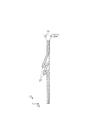
図1には、本実施の形態のマスク10を外面側から視た様子が、また図2にはこのマスク10を内面側から視た様子が示されている。ここで、マスク10の内面は、マスク装着時にマスク着用者の顔と対向する面として規定され、その反対側の面がマスク10の外面として規定される。これら図1及び図2によれば、マスク10は、特にマスク着用者の口(口元)及び鼻(鼻腔)を主体に被覆するマスク本体部20と、マスク本体部20に連接されマスク着用者の耳への引っ掛けに用いる一対の耳掛け部30,30を含む構成とされる。このマスク10は、1回ないし数回の使用を想定した使い捨てマスクとして使用されるのが好ましく、その用途として典型的には、風邪などのウィルス対策、花粉対策等が挙げられる。ここでいうマスク本体部20及び一対の耳掛け部30,30がそれぞれ、本発明における「マスク本体部」及び「耳掛け部」に相当する。
FIG. 1 shows a state in which the
マスク本体部20は、図1に示すように、第1の方向11及びその第1の方向11と交差する第2の方向12にそれぞれ延在する平坦状の平面部20aを有する。ここでいう平面部20aが、本発明における「平面部」に相当する。また、ここでいう第1の方向11及び第2の方向12がそれぞれ、本発明における「第1の方向」及び「第2の方向」に相当する。マスク本体部20が横幅L1で縦幅L2(<L1)の長方形とされている場合には、第1の方向11はマスク本体部20の横幅方向としても規定され、また第2の方向12はマスク本体部20の縦幅方向としても規定される。このマスク本体部20の第1の方向11上の2つの端部領域21,21にはそれぞれ、接合点22が第2の方向12に沿って直線状に延在している。この接合点22は、マスク本体部20と各耳掛け部30とを互いに融着(「溶着」ともいう)する接合部分として構成される。この場合の融着として、熱によるものや超音波によるものを適宜用いることができる。また、マスク本体部20の第2の方向12上の一方の端部領域23には、それぞれ第1の方向11に沿って直線状に延在する2つの接合点24,24が略平行に配置されている。これら接合点24,24によってマスク本体部20の内部に収容空間25が形成され、この収容空間25には、マスク着用者の鼻上部の形状に適合するように変形可能なノーズフィット部材26が収容されている。なお、上記の接合点22,24における各融着に代えて、或いは加えて、接着剤による接合を用いることもできる。
As shown in FIG. 1, the mask
マスク本体部20は、平面部20a上を第1の方向11に延在して形成される複数の襞(プリーツ)27を備えている。これらの襞27は、端部領域21においては襞付けされた状態で接合点22によって接合されており、従って端部領域21での第2の方向12に沿った展開動作が阻止され、且つ第1の方向11上の両端部領域21,21間の中間領域28にて当該展開動作が可能となるように構成される。ここでいう襞27及び中間領域28がそれぞれ、本発明における「襞」及び「中間領域」に相当する。
The
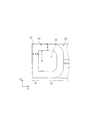
図2に示すように、一対の耳掛け部30,30は、マスク本体部20の内面側に接合された耳掛けシート30aによって形成されている。この耳掛けシート30aは、単一のシート状不織布からなる。即ち、この耳掛けシート30aでは、2つの耳掛け部30,30が互いに連接しつつ同一平面上に延在している。また、マスク10は、当該マスク10の平面視でマスク本体部20の外形内に耳掛けシート30aが収まるように構成されている。これにより、マスク本体部20と各耳掛け部30との重なり部分をそのまま接合することによって、マスクを製造することができ、特にマスクを連続的に製造する際の取り扱いが容易になる。また、単一シート状の耳掛けシート30aによって両耳掛け部30,30が構成されるため、マスク製造時の部品点数を抑えることができる。この場合、マスク本体部20の第1の方向11又は第2の方向12の長さが、耳掛けシート30a(耳掛け部30)の第1の方向11又は第2の方向12の長さと概ね合致する構成であってもよいし、或いはマスク本体部20の第1の方向11又は第2の方向12の長さが、耳掛けシート30a(耳掛け部30)の第1の方向11又は第2の方向12の長さを上回る構成であってもよい。これにより、マスク10の平面視でマスク本体部20の外形内に一対の耳掛け部30,30が収まることとなる。
As shown in FIG. 2, the pair of ear hooks 30, 30 is formed by an
耳掛けシート30aの各耳掛け部30は、単一のシート状不織布で互いに一体状に形成された接合部31及び環状部32を有し、さらに接合部31がマスク本体部20の端部領域21に接合点22を介して融着によって接合されている。即ち、マスク本体部20の一方の端部領域21に一方の耳掛け部30の接合部31が接合され、またマスク本体部20の他方の端部領域21に他方の耳掛け部30の接合部31が接合されている。これにより、耳掛け部30の構造、及び接合部31と端部領域21との接合構造を簡素化できる。特に、接合部31は、第2の方向12について端部領域21のほぼ全体にわたり延在しつつ、接合点22を介して端部領域21に融着された部位として構成される。この場合、マスク本体部20の端部領域21の第2の方向12についての2つの角部(図2中の上下の角部)はそれぞれ、耳掛け部30の接合部31の第2の方向12についての2つの角部(図2中の上下の角部)に合致するのが好ましい。
Each
各耳掛け部30の接合部31及び環状部32は互いに環状に連接されており、これにより当該耳掛け部30の開口部分である耳掛け空間33を形成している。即ち、環状部32は、接合部31とともに耳掛け空間33を形成する部位として構成される。この耳掛け空間33は、接合部31と環状部32との間に閉じた状態で形成され、環状部32がマスク着用者の耳に引っ掛けられた場合に当該耳を収容する機能を果たす。これにより、耳掛け空間33を有する耳掛け部30を、耳掛け空間33に対応した簡単な形状の打ち抜き部材による打ち抜き加工によって製造することができる。その変更例として、耳掛け部30が切り込み加工された開口部分によって耳掛け空間33を形成することもできる。
The
また、耳掛けシート30aは、一方の耳掛け部30の環状部32と、他方の耳掛け部30の環状部32との連接部分に接続部34が設けられている。これにより、単一シート状の耳掛けシート30aにおいて両耳掛け部30,30が環状部32にて互いに連接した構成が実現される。この接続部34は、一方の耳掛け部30と他方の耳掛け部30を、マスク本体部20の外形内で互いに接続する接続部分として構成されている。これにより、両耳掛け部30,30が予め接続部34で接続されて一体化された状態での取り扱いが可能となる。また、両耳掛け部30,30を互いに接続する接続部34を設けることで、マスク10が未使用状態であることが容易に認識される。また、この接続部34は、各耳掛け部30を手で引っ張ることによって当該接続部34の接続が解除可能となるように、即ち規定の引っ張り荷重を下回る接続強度を有するように構成されている。このため、典型的には、一方の環状部32と他方の環状部32とをミシン目や接着剤を介して互いに接続する形態などを用いることによって接続部34を構成するのが好ましい。これにより、マスク着用者は、一対の耳掛け部30,30の接続部34での接続を容易に解除してマスクの使用に備えることができる。この接続部34は、1点又は複数点からなる接続部分であってもよいし、第2の方向12に沿って延在する線状の接続部分であってもよい。また、接続部34は、ハサミやカッター等での切断処理を要する程度の接続強度を有する接続部分あってもよい。また、両耳掛け部30,30は、単一の耳掛けシート30aによって一体状に構成される形態に代えて、それぞれ別体に構成される形態であってもよい。別体の場合は、両耳掛け部30,30が接続部で互いに接続された状態で同一平面上に延在する構成であってもよいし、或いは接続部において互いに重なり合う構成であってもよい。
Further, the
上記構成のマスク本体部20の断面構造については、図3及び図4が参照される。これらの図面に示す第3の方向13は、第1の方向11及び第2の方向12の双方に交差する方向として構成される。この第3の方向13は、マスク本体部20又は耳掛けシート30a(耳掛け部30)のシート厚み方向として、或いはマスク本体部30と耳掛けシート30a(耳掛け部30)との重ね合わせ方向としても規定される。図3によれば、複数の襞27は、マスク本体部20の外面側は折り山(「折り目」ないし「襞山」ともいう)が上下に外側に折られ、マスク本体部20の内面側の折り山が突合せ状に形成された襞付けの形態(「箱折り」ともう)として構成される。なお、図3に示すこの襞付けの形態は、必要に応じて適宜に選択が可能であり、例えば図4に示すような、マスク本体部20の外面側に折り山を繰り返し作る襞付けの形態や、図5に示すような、マスク本体部20の内面側に折り山を繰り返し作る襞付けの形態を採用することもできる。
3 and 4 are referred to for the cross-sectional structure of the mask
図6に示すように、図3中のマスク本体部20は、更にいずれもシート状不織布からなる外側シート20b、及び中間シート20c及び内側シート20dを含み、これらシートが第3の方向13について順次重ねられた3層構造になっている。
As shown in FIG. 6, the mask
外側シート20bは、マスク本体部20の外面、即ちマスク着用状態で外側に露出する面を有する。内側シート20dは、マスク本体部20の内面、即ちマスク着用状態でマスク着用者に対向する面を有する。これら外側シート20b及び内側シート20dはいずれも、既知のスパンボンド(SB)不織布、ポイントボンド(PB)不織布、スパンレース(SL)不織布、エアスルー(AT)不織布などによって構成され、その目付が例えば10〜100g/m2の範囲で適宜設定されるのが好ましい。これによりマスク本体部20の所望の通気性が確保される。
The
中間シート20cは、塵埃、細菌、ウィルスなどについて所定の捕集性を有するフィルターシートとして構成される。この中間シート20cは、既知のメルトブロー(MB)不織布などによって構成され、その目付が例えば1〜50g/m2の範囲で適宜設定されるのが好ましい。これによりマスク本体部20の所望の通気性が確保され、且つ所望の捕集性が確保される。なお、この中間シート20cを、ホットメルト接着剤(HMA)を用いて外側シート20bと一体化された構成を採用することもできる。
The
一方、耳掛け部30の材質として、既知の伸縮スパンボンド(SB)不織布、伸縮スパンボンド・マイクロウェブ・スパンボンド(SMS)不織布、伸縮スパンボンド・フイルム・スパンボンド不織布、伸張性スパンレース不織布、伸縮ホットメルト接着剤(HMA)不織布などを用いることができ、また当該不織布の目付が例えば20〜120g/m2の範囲で適宜設定されるのが好ましい。これにより耳掛け部30の所望の伸縮性が確保される。
On the other hand, as the material of the
図7には、マスク本体部20の複数の襞27が第2の方向12に沿って展開動作した様子が示されている。図7に示すように、マスク使用時においてマスク本体部20は、各端部領域21では複数の襞27の第2の方向12に沿った展開動作が阻止される一方で、中間領域28では、複数の襞27の第2の方向12に沿った展開動作(「マスク展開部20の展開動作」ともいう)が可能とされている。このとき、各端部領域21は、第2の方向12の沿った長さが拡張されることなく湾曲形状をなす一方で、中間領域28は、第2の方向12の沿った長さL3を拡張しつつ湾曲形状をなす。これにより、マスク本体部20は、マスク着用者側が凹んだ立体形状をなし、マスク本体部20の内面とマスク着用者との間に所定の口元空間29が形成される。
FIG. 7 illustrates a state in which the plurality of
図8には、図7に示す状態のマスク10を着用したマスク着用者を横から視た様子が示されている。図8によれば、耳掛け部30の環状部32がマスク着用者の耳に引っ掛けられることによって、当該マスク着用者の顔面がマスク本体部20によって被覆される。このとき、マスク本体部20の端部領域21が湾曲形状をなすため、当該端部領域21とマスク着用者の頬部との間に隙間が生じ易い。そこで本実施の形態のマスク10は、この隙間を抑えるべく以下に説明する構成(以下、「隙間抑制機構」ともいう)を有している。
FIG. 8 shows a state where the mask wearer wearing the
<長尺延在部>
即ち、本実施の形態のマスク10では、隙間抑制機構は、耳掛け部30の接合部31が、第2の方向12について端部領域21のほぼ全体にわたり長尺状に延在するように構成された長尺延在部を含む。これにより、マスク着用時に環状部32に生じる張力が接合部31に作用することで、接合部31がマスク着用者の頬部の形状に追従して当該頬部との密着性を高めることができ、図8に示すように、特に端部領域21とマスク着用者の顔面との間の境界部41に隙間が生じるのを抑えることができる。また、このとき、耳掛け部30の接合部31の上側の角部が、マスク本体部20の端部領域21の上側の角部に連接し、また耳掛け部30の接合部31の下側の角部が、マスク本体部20の端部領域21の下側の角部に連接する。これにより、図8に示すように、境界部41の両側の境界部42,43において、端部領域21とマスク着用者の顔面との間に隙間が生じるのを接合部31の上下の角部によって抑えることができる。かくして、マスク本体部20の端部領域21とマスク着用者の顔面との間に隙間が生じるのを、耳掛け部30の接合部31により第2の方向12について境界部41〜43の広範囲にわたって抑えることができる。
<Long extension part>
That is, in the
更に、隙間抑制機構は、マスク本体部20又は耳掛け部30の構成を以下のように具現化した種々の寸法設定部や湾曲部を含むことによって、更なる隙間抑制効果を発揮することが可能となる。
Furthermore, the gap suppression mechanism can exhibit a further gap suppression effect by including various dimension setting parts and curved parts that embody the configuration of the mask
<第1の寸法設定部>
図9に示すように、本実施の形態では、接合部31の第1の方向11の長さをa[mm]とし、接合部31のうち耳掛け空間33の第2の方向12の距離を規定する長さをb[mm]とし、さらに10mmから70mmまでの寸法値から予め選択された定数値をC[mm]とした場合に、b=2a+Cの関係が成り立つように設定された耳掛け部30によって、第1の寸法設定部が構成されるのが好ましい。これにより、マスク着用者の頬部の形状に対する接合部31の追従効果を高めることで、前述の境界部41〜43に生じる隙間を確実に抑えることが可能な耳掛け部の寸法設定を実現できる。
<First dimension setting unit>
As shown in FIG. 9, in the present embodiment, the length of the
<第2の寸法設定部>
また、接合部31の第1の方向11の長さaを30mm以下の寸法値となるように設定された耳掛け部30によって、第2の寸法設定部が構成されるのが好ましい。即ち、耳掛け部30の接合部31は、第1の方向11に関し所定範囲内の延在長さを有するのが好ましい。これにより、一方では長さaを増やすことによって特に前述の境界部41に生じる隙間が抑えられるという作用効果が得られ、且つ、他方では長さaの増やし過ぎで接合部31にしわが発生するのを抑えることで、見栄えが悪くなるのを阻止できるという作用効果が得られる。
<Second dimension setting unit>
Moreover, it is preferable that the second dimension setting section is configured by the
<第3の寸法設定部>
また、環状部32のシート幅d[mm]が10mmから30mmまでの寸法値となるように設定された耳掛け部30によって、第3の寸法設定部が構成されるのが好ましい。即ち、耳掛け部30の環状部32は、所定範囲内のシート幅を有するのが好ましい。これにより、一方では環状部32のシート幅dが細過ぎて耳が痛くなりそうな印象をマスク着用者に与えるのを阻止できるという作用効果が得られ、且つ、他方では環状部32のシート幅dが太過ぎて見栄えが悪くなるのを阻止できるという作用効果が得られる。
<Third dimension setting unit>
In addition, it is preferable that the third dimension setting unit is configured by the
<第4の寸法設定部>
また、第1の方向11の長さL1[mm]が100mmから180mmまでの寸法値となるように設定されたマスク本体部20によって、第4の寸法設定部が構成されるのが好ましい。即ち、マスク本体部20は、第1の方向11に関し所定範囲内の延在長さを有するのが好ましい。これにより、一方では、マスク本体部20の第1の方向11の寸法が小さ過ぎるという不安感をマスク着用者に与えるのを阻止できるという作用効果が得られ、且つ、他方ではマスク本体部20が第1の方向11に大きくなり過ぎて隙間が生じたりフィット感が悪化し、また見栄えが悪くなるのを阻止できるという作用効果が得られる。
<Fourth dimension setting section>
In addition, it is preferable that the fourth dimension setting unit is configured by the mask
<第5の寸法設定部>
また、第2の方向12の長さL2[mm]が70mmから100mmまでの寸法値となるように設定されたマスク本体部20によって、第5の寸法設定部が構成されるのが好ましい。即ち、マスク本体部20は、第2の方向12に関し所定範囲内の延在長さを有するのが好ましい。これにより、一方では、マスク本体部20の第2の方向12の寸法が小さ過ぎるという不安感をマスク着用者に与えるのを阻止できるという作用効果が得られ、且つ、他方ではマスク本体部20が第2の方向12に大きくなり過ぎて隙間が生じたりフィット感が悪化し、また見栄えが悪くなるのを阻止できるという作用効果が得られる。
<5th dimension setting part>
In addition, it is preferable that the fifth dimension setting unit is configured by the mask
<第6の寸法設定部>
また、複数の襞27が展開動作で展開したときの中間領域28の第2の方向12に沿った展開長さL3[mm]が135mmから175mmまでの寸法値となるように設定されたマスク本体部20によって、第6の寸法設定部が構成されるのが好ましい。即ち、マスク本体部20は、第2の方向12に沿った所定範囲内の展開長さで展開するように襞27が構成されるのが好ましい。これにより、マスク着用者の顔面に対するマスク本体部20のフィット感を高めることで隙間を抑制できるという作用効果が得られる。
<Sixth dimension setting unit>
Further, the mask main body is set such that the development length L3 [mm] along the
<湾曲部>
マスク本体部20は、中間領域28における複数の襞27の展開動作に伴って端部領域21が湾曲し、これによって接合部31とマスク着用者の顔面との隙間を抑える湾曲部を備えるのが好ましい。この湾曲部は、典型的には湾曲時の曲率半径が相対的に大きくなるように設定された、或いは湾曲時の第2の方向12に沿った長さL2が相対的に小さくなるように設定された端部領域21によって構成される。これにより、マスク装着時にマスク本体部20の端部領域21が湾曲した場合、マスク着用者の頬部の形状に対する端部領域21の追従効果を高めることで、この湾曲によって生じる隙間の発生を抑えることが可能となる。また、この湾曲部は、端部領域21の前述の湾曲時の曲率半径をR[mm]とした場合に、当該曲率半径に対する端部領域21の第2の方向12に沿った長さL2[mm]の比率(L2/R)が2から3.5までの値となるように設定された端部領域21によって構成されるのが好ましい。これにより、マスク装着時にマスク本体部の端部領域が湾曲した場合に生じる隙間の発生を抑えることが可能な湾曲部の好適な寸法設定を実現できる。
<Curved part>
The mask
上記構成のマスク10に係る製造装置及び製造方法について、図10〜図13を参照しつつ以下に説明する。
A manufacturing apparatus and a manufacturing method according to the
図10には、マスク製造装置100の概要が示されている。この製造装置100は、外側シート供給装置101、内側シート供給装置102、中間シート供給装置103、シート重ね装置104、ノーズフィット差し込み装置105、襞付け装置106、エンドカット装置107、耳掛けシート供給装置121、打ち抜き装置122、方向転換装置131、保持ロール141、接合装置151を含む構成とされる。このマスク製造装置100では、当該装置を構成する上記の各構成要素が適宜に省略されてもよいし、或いは別の構成要素が付加されてもよい。
FIG. 10 shows an outline of the
外側シート供給装置101は、前述の外側シート20bを形成するための長尺帯状の外側シート帯101aを準備して供給する装置として構成される。同様に、内側シート供給装置102は、前述の内側シート20dを形成するための長尺帯状の内側シート帯102aを準備して供給する装置とされ、また中間シート供給装置103は、前述の中間シート20cを形成するための長尺帯状の中間シート帯103aを準備して供給する装置として構成される。シート重ね装置104は、外側シート帯101aと内側シート帯102aとの間に中間シート帯103aが挟み込まれるように積層された3層構造の積層シート帯104aを形成しつつ当該積層シート帯104aを搬送するための装置として構成される。ノーズフィット差し込み装置105は、前述のノーズフィット部材26(図1参照)を形成するための差し込み部材105aを積層シート帯104aの収容空間に差し込むための装置として構成される。差し込み部材105aが差し込まれた積層シート帯104aは、襞付け装置106によって襞27の襞付け処理がなされ、その後にエンドカット装置107で、個別のマスク本体部20にカットされる。各マスク本体部20は、その後に方向転換装置131で所定の方向転換がなされ、更に保持ロール141で保持されつつ接合装置151へと搬送される。
The outer
上述のように、外側シート供給装置101、内側シート供給装置102及び中間シート供給装置103から、シート重ね装置104、ノーズフィット差し込み装置105、襞付け装置106、エンドカット装置107及び方向転換装置131を経て保持ロール141へと至る一連の設備は、所定の低伸長方向(図1中の第1の方向11)と交差する高伸長方向(図1中の第2の方向12)に伸長し易いマスク本体部20を準備し、そのマスク本体部20を当該マスク本体部20の低伸長方向(図1中の第1の方向11)に沿って搬送する搬送ステップ(第1の搬送ステップ)を行うべく制御される。この搬送ステップが、本発明における「第1の搬送ステップ」に相当する。
As described above, from the outer
一方、耳掛けシート供給装置121は、耳掛けシート30a(一対の耳掛け部30,30)を複数形成するための長尺帯状の耳掛けシート帯121aを準備して供給する装置として構成される。即ち、この耳掛けシート帯121aには、複数対の耳掛け部30,30が含まれる。耳掛けシート帯121aは、その長尺延在方向(「低伸長方向」ともいう)よりも当該長尺延在方向と交差する方向(「高伸長方向」ともいう)に伸長し易い不織布シートとして構成されている。この耳掛けシート帯121aは、その低伸長方向に沿って搬送されつつ打ち抜き装置122によって打ち抜き処理される。打ち抜き装置122は、ダイカッター123及びアンビルロール125からなる。ダイカッター123は、吸引装置(図示省略)によってシート保持面124に耳掛けシート帯121aを保持しつつ、シート保持面124の凸状打ち抜き刃を、アンビルロール125のロール表面126に回転押圧することで、当該耳掛けシート帯121aを打ち抜き処理する。具体的には、この打ち抜き処理によって、耳掛けシート帯121aのうち耳掛け部30に相当する部位以外が打ち抜かれ、これにより図2中の耳掛けシート30aを複数含む、即ち複数対の耳掛け部30を含む耳掛けシート帯121bが形成される。打ち抜き処理がなされたこの耳掛けシート帯121bは、その後に、保持ロール141によって保持されているマスク本体部20とともに接合装置151へと搬送される。
On the other hand, the ear hanger
上述のように、耳掛けシート供給装置121から、打ち抜き装置122を経て接合装置151へと至る一連の設備は、所定の低伸長方向(図1中の第2の方向12)と交差する高伸長方向(図2中の第1の方向11)に伸長し易い耳掛けシート帯121b(複数対の耳掛け部30を含む耳掛けシート帯)を準備し、その耳掛けシート帯121bを耳掛け部30の低伸長方向(図1中の第2の方向12)に沿って搬送する搬送ステップ(第2の搬送ステップ)を行うべく制御される。この搬送ステップが、本発明における「第2の搬送ステップ」に相当する。
As described above, a series of equipment from the ear hooking
その後、各マスク本体部20は耳掛けシート帯121bとともに接合装置151に連続的に導入されて、耳掛けシート帯121bに接合される。即ち、この接合装置151は、前述の第1の搬送ステップで搬送のマスク本体部20と、前述の第2の搬送ステップで搬送の耳掛けシート帯121b(複数対の耳掛け部30を含む不織布シート)を互いに接合する接合ステップを行うべく制御される。この接合ステップは、マスク本体部20や耳掛けシート帯121bの搬送ステップと同時並行で遂行されてもよいし、或いは当該搬送ステップとは別個に遂行されてもよい。この接合ステップが、本発明における「接合ステップ」に相当する。その後、余分なはみ出し部分をカットする処理等、種々の最終的な後処理がなされることによって、マスク本体部20及び一対の耳掛け部30からなる図1中のマスク10が製造される。
Then, each mask main-
上記の方向転換装置131及び保持ロール141の具体的な構成については図11が参照される。図11によれば、方向転換装置131は、図中の矢印130方向(反時計まわりに)に回転動作される回転体132と、その回転体132の外周面に支持軸133を介してそれぞれ取り付けられた複数の(図11では12つの)方向転換部134を備える。各方向転換部134は、吸引装置(図示省略)によってシート保持面135に1つのマスク本体部20を吸引保持した状態で支持軸133まわりに回転動作することで、当該マスク本体部20の方向転換処理を行うとともに、回転体132の回転動作に伴って当該マスク本体部20を保持ロール141側へと搬送する。保持ロール141は、図中の矢印140方向(時計まわりに)に回転動作される回転体142を有し、方向転換装置131から搬送された複数のマスク本体部20を、吸引装置(図示省略)によってシート保持面142に保持しつつ回転動作される。
FIG. 11 is referred to for specific configurations of the
ところで、各マスク本体部20は、襞27等の影響によって第1の方向11よりも第2の方向12に伸長し易く、これによりマスク製造時の搬送の際、当該マスク本体部20の変形、歪み、位置ずれ等が生じる不具合が想定される。ここで、マスク本体部20については、図1中の第1の方向11が相対的に伸長度合の低い低伸長方向とされ、図1中の第2の方向12が相対的に伸長度合の高い高伸長方向として構成される。一方、各耳掛け部30については、図2中の第2の方向12が相対的に伸長度合の低い低伸長方向とされ、図2中の第1の方向11が相対的に伸長度合の高い高伸長方向として構成される。前述の不具合を抑えるためには、当該マスク本体部20を第2の方向12よりも伸長し難い第1の方向11に沿って搬送する必要がある。一方で、各マスク本体部20は、耳掛けシート帯121bとの接合に際しては、当該マスク本体部20の低伸長方向と耳掛けシート帯121bの高伸長方向とが概ね合致するように、即ちマスク本体部20と一対の耳掛け部30が図2に示すように配置される必要がある。
By the way, each mask
そこで、本実施の形態では、前述の第1の搬送ステップでの各マスク本体部20の搬送方向を、当該マスク本体部20の低伸長方向(図1中の第1の方向11)に沿った方向とすることを基本としている。これにより、マスク製造時の搬送の際、マスク本体部20の変形、歪み、位置ずれ等が生じるのを抑えることができ、従って、マスク製造時の取り扱いが容易になる。一方で、各マスク本体部20と耳掛けシート帯121bを互いに接合する前述の接合ステップの直前において、方向転換装置131によって、耳掛けシート帯121bに対する各マスク本体部20の相対位置を変更するように、より具体的には各マスク本体部20の搬送方向を、その低伸長方向に沿った方向からその高伸長方向に沿った方向へと転換するようにしている。これにより、接合ステップの前に、マスク本体部20の低伸長方向と耳掛けシート帯121b(耳掛け部30)の高伸長方向とが概ね合致するように、マスク本体部20及び耳掛けシート帯121b(耳掛け部30)の相対位置が変更される。従って、方向転換装置131によるこのステップが、本発明における「相対位置変更ステップ」に相当する。なお、耳掛けシート帯121bの代わりに前述の耳掛けシート30aを用い、この耳掛けシート30a又はマスク本体部20の搬送方向を、その低伸長方向に沿った方向からその高伸長方向に沿った方向へと転換することによって、マスク本体部20及び耳掛け部30の相対位置を変更するように構成することもできる。
Therefore, in the present embodiment, the transport direction of each
ここで、上記方向転換装置131における各方向転換部134の具体的な処理については図12が参照される。図12では、方向転換部134が12時の位置にある場合を図中の(a)で示し、方向転換部134が9時の位置にある場合を図中の(b)で示し、方向転換部134が6時の位置にある場合を図中の(c)で示している。図12によれば、各方向転換部134は、回転体132のまわりを12時の位置(上死点)から9時の位置を経て6時の位置(下死点)まで矢印130方向に沿って回転動作する過程で、支持軸133を中心に時計まわりにほぼ90度回転動作することで方向転換処理がなされる。これにより、各方向転換部134のシート保持面135上に保持されているマスク本体部20は、そのシート延在面上でほぼ90度回転される。各方向転換部134は、6時の位置(下死点)まで回転動作したときに、各マスク本体部20を保持ロール141側へと受け渡す。その後、各方向転換部134は、各マスク本体部20の保持を解除した状態で、回転体132のまわりを6時の位置(上死点)から3時の位置を経て12時の位置(下死点)まで矢印130方向に沿って回転動作するとともに、支持軸133を中心に時計まわりに90度回転動作する。かくして、各方向転換部134は、再び12時の位置(上死点)まで回転動作することで、次のマスク本体部20の保持を行う。
Here, FIG. 12 is referred to for specific processing of each
マスク本体部20と耳掛けシート帯121bが所定の配置態様で互いに重ね合わされる様子については、図13が参照される。図13によれば、保持ロール141のシート保持面142では、各マスク本体部20は、襞27の延在方向と交差する送り方向(矢印140方向)に沿って、即ち当該マスク本体部20の高伸張方向に沿って送られる。一方で、ダイカッター123のシート保持面124では、耳掛けシート帯121bは、一対の耳掛け部30の連接方向と交差する送り方向(矢印120方向)に沿って、即ち当該耳掛けシート帯121b(耳掛け部30)の低伸張方向に沿って送られる。これにより、各マスク本体部20及び耳掛けシート帯121bは、マスク本体部20の低伸長方向と耳掛けシート帯121b(耳掛け部30)の高伸長方向が概ね合致するように配置された配置状態で互いに重ねられ、その配置状態のまま接合装置151へと搬送されて互いに接合される。従って、本実施の形態によれば、マスク本体部20及び耳掛けシート帯121bをそれぞれ伸長し難い方向に沿って搬送した後に、マスク本体部20の低伸長方向と耳掛けシート帯121b(耳掛け部30)の高伸長方向とを概ね合致させた状態で、マスク本体部20と耳掛けシート帯121bを互いに接合させることができる。
FIG. 13 is referred to for the manner in which the mask
上記の製造方法では、マスク本体部20と耳掛け部30(耳掛けシート帯121b)の接合に際し、これらマスク本体部20と耳掛け部30の双方を移動させて両者の相対位置を変更する場合について記載したが、本発明では、固定された状態のマスク本体部20に対して耳掛け部30を移動させることによって、或いは固定された状態の耳掛け部30に対してマスク本体部20を移動させることによって、両者の相対位置を変更するようにしてもよい。
In the above manufacturing method, when the mask
(他の実施の形態)
なお、本発明は上記の実施の形態のみに限定されるものではなく、種々の応用や変形が考えられる。例えば、上記実施の形態を応用した次の各形態を実施することもできる。
(Other embodiments)
In addition, this invention is not limited only to said embodiment, A various application and deformation | transformation can be considered. For example, each of the following embodiments to which the above embodiment is applied can be implemented.
上記実施の形態では、マスク本体部20を3層のシート不織布からなる3層構造とする場合について記載したが、本発明では、シート不織布の数、種類、積層数については必要に応じて適宜選択が可能である。
In the said embodiment, although the case where the mask main-
また、上記実施の形態では、一回使用ないし数回使用を目安とした使い捨てタイプのマスクについて記載したが、マスク本体部20や耳掛け部30の素材を適宜選択することによって、洗濯などを行ったうえで繰り返し使用することが可能なタイプのマスクに対し本発明を適用することもできる。
Further, in the above embodiment, the disposable type mask that is intended to be used once or several times has been described. However, by appropriately selecting the material of the mask
上記実施の形態や種々の変更例の記載に基づいた場合、本発明では、以下の各態様を採用することができる。 In the present invention, the following aspects can be employed based on the description of the above embodiment and various modified examples.
(態様1)
「マスク本体部と、前記マスク本体部に連接される耳掛け部と、を備えるマスクの製造方法であって、
所定の低伸長方向と交差する高伸長方向に伸長し易いマスク本体部を準備し、前記マスク本体部を当該マスク本体部の低伸長方向に沿って搬送する第1の搬送ステップと、
所定の低伸長方向と交差する高伸長方向に伸長し易い耳掛け部を準備し、前記耳掛け部を当該耳掛け部の低伸長方向に沿って搬送する第2の搬送ステップと、
前記第1の搬送ステップで搬送の前記マスク本体部と、前記第2の搬送ステップで搬送の前記耳掛け部を互いに接合する接合ステップと、
前記接合ステップの前に、前記マスク本体部の低伸長方向と前記耳掛け部の高伸長方向とが概ね合致するように、前記マスク本体部及び前記耳掛け部の相対位置を変更する相対位置変更ステップと、
を含むことを特徴とする、マスクの製造方法」という態様を採り得る。
(Aspect 1)
“A mask manufacturing method comprising a mask body and an ear hook connected to the mask body,
Preparing a mask main body portion that is easy to extend in a high extension direction intersecting a predetermined low extension direction, and transferring the mask main body portion along the low extension direction of the mask main body portion;
A second transporting step of preparing an ear hook that is easy to extend in a high extension direction that intersects a predetermined low extension direction, and transporting the ear hook along the low extension direction of the ear hook;
A joining step for joining the mask main body part for transportation in the first transportation step and the ear hooking part for transportation in the second transportation step;
Relative position change for changing the relative positions of the mask main body and the ear hook so that the low extension direction of the mask main body and the high extension direction of the ear hook substantially match before the joining step. Steps,
The method of manufacturing a mask characterized by including "can be adopted.
(態様2)
「態様1に記載の、マスクの製造方法であって、
前記相対位置変更ステップは、前記マスク本体部と前記耳掛け部のいずれか一方の搬送方向を、その低伸長方向に沿った方向からその高伸長方向に沿った方向へと転換することで、前記マスク本体部及び前記耳掛け部の相対位置を変更するステップとされることを特徴とする、マスクの製造方法」という態様を採り得る。
(Aspect 2)
“A method of manufacturing a mask according to aspect 1,
In the relative position changing step, the transfer direction of either the mask body part or the ear hooking part is changed from a direction along the low extension direction to a direction along the high extension direction, A mode of “a method of manufacturing a mask,” which is a step of changing the relative positions of the mask main body portion and the ear hooking portion can be employed.
(態様3)
「態様2に記載の、マスクの製造方法であって、
前記マスク本体部はシート状に構成され、
前記相対位置変更ステップは、前記第1の搬送ステップで搬送の前記マスク本体部を、そのシート延在面上でほぼ90度回転させることによって、当該マスク本体部の搬送方向を、その低伸長方向に沿った方向からその高伸長方向に沿った方向へと転換するステップとされることを特徴とする、マスクの製造方法」という態様を採り得る。
(Aspect 3)
“A method of manufacturing a mask according to aspect 2,
The mask body is configured in a sheet shape,
In the relative position changing step, the mask main body portion transported in the first transport step is rotated by approximately 90 degrees on the sheet extending surface, thereby changing the transport direction of the mask main body portion in the low extension direction. It is possible to adopt a mode of “a method of manufacturing a mask,” which is a step of changing from a direction along the direction to a direction along the high extension direction.
(態様4)
「態様1から3のうちのいずれかに記載の製造方法によって製造されたマスクであって、
前記マスク本体部及び前記耳掛け部は、いずれもシート状不織布によって構成され、
前記マスク本体部は、当該マスク本体部の低伸長方向上の端部領域に前記耳掛け部が融着によって接合され、これによって当該マスク本体部の低伸長方向が前記耳掛け部の高伸長方向と概ね合致するように構成されていることを特徴とするマスク」という態様を採り得る。
(Aspect 4)
"A mask manufactured by the manufacturing method according to any one of aspects 1 to 3,
The mask main body and the ear hook are both composed of a sheet-like nonwoven fabric,
The mask body is joined to the end region in the low extension direction of the mask body by fusion bonding, whereby the low extension direction of the mask body is the high extension direction of the ear hook. And a “mask characterized by being configured so as to substantially match”.
(態様5)
「態様4に記載のマスクであって、
前記マスク本体部は、当該マスク本体部の低伸長方向上の両端部領域間の中間領域と、前記中間領域に当該マスク本体部の低伸長方向に延在して形成される襞と、を有し、前記中間領域において前記襞の当該マスク本体部の高伸長方向に沿った展開動作が可能とされ、これにより当該マスク本体部がその高伸長方向に伸長し易い構成とされていることを特徴とするマスク」という態様を採り得る。
(Aspect 5)
“The mask according to aspect 4,
The mask main body has an intermediate region between both end regions in the low extension direction of the mask main body, and a ridge formed in the intermediate region so as to extend in the low extension direction of the mask main body. In the intermediate region, the wrinkle can be unfolded along the high extension direction of the mask main body portion, whereby the mask main body portion is easily extended in the high extension direction. The aspect of “a mask” can be taken.
(態様6)
「マスク本体部と、前記マスク本体部に連接される耳掛け部と、を備えるマスクであって、
前記マスク本体部は、シート状不織布で形成されるとともに、所定の第1の方向及び前記第1の方向と交差する第2の方向にそれぞれ延在する平面部と、前記第1の方向上の端部領域と、を有し、
前記耳掛け部は、シート状不織布で形成されるとともに、前記端部領域に融着によって接合され、
前記マスク本体部が前記第1の方向よりも前記第2の方向に伸長し易く、且つ前記耳掛け部が前記第2の方向よりも前記第1の方向に伸長し易い構成であることを特徴とするマスク」という態様を採り得る。
(Aspect 6)
“A mask comprising a mask main body and an ear hook connected to the mask main body,
The mask body is formed of a sheet-like non-woven fabric, and extends in a predetermined first direction and a second direction intersecting the first direction, and on the first direction. An end region, and
The ear hook is formed of a sheet-like non-woven fabric and joined to the end region by fusion,
The mask main body portion is configured to be easier to extend in the second direction than the first direction, and the ear hooking portion is easier to extend in the first direction than the second direction. The aspect of “a mask” can be taken.
(態様7)
「態様6に記載のマスクであって、
前記マスク本体部は、前記第1の方向上の両端部領域間の中間領域と、前記中間領域に前記第1の方向に延在して形成される襞と、を有し、前記中間領域において前記襞の前記第2の方向に沿った展開動作が可能とされ、これにより前記第1の方向よりも前記第2の方向に伸長し易い構成とされていることを特徴とするマスク」という態様を採り得る。
(Aspect 7)
“The mask according to aspect 6,
The mask main body includes an intermediate region between both end regions in the first direction, and a ridge formed in the intermediate region so as to extend in the first direction. A mode of “a mask characterized in that the unfolding movement of the ridge along the second direction is possible, and the structure is thus easier to extend in the second direction than in the first direction”. Can be taken.
(態様8)
「態様1から3のうちのいずれかに記載の、マスクの製造方法であって、
前記マスク本体部は、外側シートと内側シートとの間に中間シートを配した構成であり、前記第1の搬送ステップは、前記外側シートを形成するための長尺帯状の外側シート帯と、前記内側シートを形成するための長尺帯状の内側シート帯との間に前記中間シートを形成するための長尺帯状の中間シート帯が挟み込まれるように積層された3層構造の積層シート帯を形成しつつ、当該積層シート帯を個別の前記マスク本体部にカットするステップを含むことを特徴とする、マスクの製造方法」という態様を採り得る。
(Aspect 8)
“A method of manufacturing a mask according to any one of aspects 1 to 3,
The mask main body has a configuration in which an intermediate sheet is disposed between an outer sheet and an inner sheet, and the first conveying step includes an elongated outer sheet band for forming the outer sheet, A three-layer laminated sheet band is formed in which a long band-shaped intermediate sheet band for forming the intermediate sheet is sandwiched between a long band-shaped inner sheet band for forming an inner sheet. However, an aspect of “a method for manufacturing a mask” including a step of cutting the laminated sheet band into the individual mask main body portions can be adopted.
(態様9)
「態様8に記載の、マスクの製造方法であって、
前記第1の搬送ステップは、マスク着用者の鼻上部の形状に適合するように変形可能なノーズフィット部材を形成するための差し込み部材を前記積層シート帯の収容空間に差し込むステップを含むことを特徴とする、マスクの製造方法」という態様を採り得る。
(Aspect 9)
“A method of manufacturing a mask according to aspect 8,
The first conveying step includes a step of inserting an insertion member for forming a nose-fit member that can be deformed so as to conform to the shape of the upper nose of the mask wearer into the accommodation space of the laminated sheet band. And a method of manufacturing a mask.
(態様10)
「態様8又は9に記載の、マスクの製造方法であって、
前記第1の搬送ステップは、前記積層シート帯に所定方向に延在する襞を形成するステップを含むことを特徴とする、マスクの製造方法」という態様を採り得る。
(Aspect 10)
“A method of manufacturing a mask according to aspect 8 or 9,
The first transporting step can take an aspect of “a method for manufacturing a mask” including a step of forming a ridge extending in a predetermined direction on the laminated sheet strip.
(態様11)
「態様1から3のうちのいずれかに記載の、マスクの製造方法であって、
前記第2の搬送ステップは、複数対の前記耳掛け部が含まれる長尺帯状の耳掛けシート帯を搬送するステップを含むことを特徴とする、マスクの製造方法」という態様を採り得る。
(Aspect 11)
“A method of manufacturing a mask according to any one of aspects 1 to 3,
The second transporting step may adopt a mode of “a method for manufacturing a mask” including a step of transporting a long strip-like ear-hanging sheet band including a plurality of pairs of the ear-hooking portions.
(態様12)
「態様11に記載の、マスクの製造方法であって、
前記第2の搬送ステップは、前記耳掛けシート帯のうち前記耳掛け部に相当する部位以外を打ち抜くステップを含むことを特徴とする、マスクの製造方法」という態様を採り得る。
(Aspect 12)
“A method of manufacturing a mask according to
The second transporting step may take a form of “a method of manufacturing a mask” including a step of punching a portion other than the portion corresponding to the ear hooking portion of the ear hooking sheet band.
(態様13)
「態様3に記載の、マスクの製造方法であって、
前記相対位置変更ステップは、前記マスク本体部を方向転換部のシート保持面に吸引保持した状態で、所定の支持軸まわりに前記方向転換部を90度回転動作することで、前記マスク本体部をそのシート延在面上でほぼ90度回転させるステップとされることを特徴とする、マスクの製造方法」という態様を採り得る。
(Aspect 13)
“A method of manufacturing a mask according to aspect 3,
In the relative position changing step, the mask main body portion is rotated 90 degrees around a predetermined support axis in a state where the mask main body portion is sucked and held on the sheet holding surface of the direction changing portion. It is possible to adopt an aspect of “a method of manufacturing a mask, which is characterized in that it is a step of rotating approximately 90 degrees on the sheet extending surface”.
(態様14)
「態様6又は7に記載のマスクであって、
前記マスク本体部の前記第2の方向上の一方の端部領域に、マスク着用者の鼻上部の形状に適合するように変形可能なノーズフィット部材が設けられていることを特徴とするマスク」という態様を採り得る。
(Aspect 14)
“The mask according to aspect 6 or 7,
A mask characterized in that a deformable nose fit member is provided in one end region of the mask main body in the second direction so as to conform to the shape of the upper part of the nose of the mask wearer. It can take the form.
(態様15)
「態様6又は7に記載のマスクであって、
前記耳掛け部は、前記第2の方向について前記端部領域のほぼ全体にわたり長尺状に延在しつつ当該端部領域に接合された接合部と、前記接合部と一体状に形成されるとともに、前記接合部とともに耳掛け空間を形成する環状部とを、有することを特徴とするマスク」という態様を採り得る。
(Aspect 15)
“The mask according to aspect 6 or 7,
The ear hooking portion is formed integrally with the joint portion and a joint portion joined to the end region while extending in an elongated shape over substantially the entire end region in the second direction. In addition, it is possible to adopt an aspect of “a mask characterized by having an annular portion that forms an ear-hanging space together with the joint portion”.
(態様16)
「態様15に記載のマスクであって、
前記マスク本体部の前記端部領域の前記第2の方向についての2つの角部はそれぞれ、前記耳掛け部の前記接合部の前記第2の方向についての2つの角部に合致するように構成されていることを特徴とするマスク」という態様を採り得る。
(Aspect 16)
“The mask according to aspect 15,
The two corners in the second direction of the end region of the mask main body are configured to match the two corners in the second direction of the joint of the ear hook. It is possible to adopt a mode of “a mask characterized by being applied”.
(態様17)
「態様15又は16に記載のマスクであって、
前記耳掛け部は、前記耳掛け空間に対応した形状の打ち抜き部材による打ち抜き加工によって形成されていることを特徴とするマスク」という態様を採り得る。
(Aspect 17)
“A mask according to aspect 15 or 16,
The said ear hook part can take the aspect of "the mask characterized by being formed by the punching process by the punching member of the shape corresponding to the said ear hook space".
(態様18)
「態様6又は7に記載のマスクであって、
前記耳掛け部は、前記マスク本体部の前記第1の方向上の両端部領域のそれぞれに接合され、
当該マスクの平面視で前記マスク本体部の外形内に前記両端部領域に接合された両耳掛け部が収まるように構成されていることを特徴とするマスク」という態様を採り得る。
(Aspect 18)
“The mask according to aspect 6 or 7,
The ear hook is joined to each of both end regions on the first direction of the mask main body,
It is possible to adopt an aspect of “a mask characterized by being configured such that both ear hooks joined to the both end regions are accommodated within the outer shape of the mask main body in a plan view of the mask”.
(態様19)
「態様18に記載のマスクであって、
前記両耳掛け部を、前記マスク本体部の外形内で互いに接続する接続部を有することを特徴とするマスク」という態様を採り得る。
(Aspect 19)
“The mask according to aspect 18,
A mode of “a mask characterized by having a connecting portion that connects the both ear hanging portions to each other within the outer shape of the mask main body portion” may be adopted.
(態様20)
「態様19に記載のマスクであって、
当該マスクの平面視で前記マスク本体部の外形内に収まるように接合された単一シート状の耳掛けシートを備え、
前記耳掛けシートは、前記両耳掛け部が前記接続部で互いに接続された状態で同一平面上に延在するように構成されており、これにより当該マスクの平面視で前記マスク本体部の外形内に前記両耳掛け部が収まることを特徴とするマスク」という態様を採り得る。
(Aspect 20)
“The mask according to aspect 19,
A single sheet-like ear-hanging sheet joined so as to fit within the outer shape of the mask body in a plan view of the mask;
The ear hook sheet is configured to extend on the same plane in a state where the both ear hook portions are connected to each other at the connection portion, whereby the outer shape of the mask main body portion in a plan view of the mask. A mode of “a mask characterized in that the both ear hooks are contained in the inside” can be adopted.
(態様21)
「態様20に記載のマスクであって、
前記耳掛けシートは、一方の前記耳掛け部の前記環状部と、他方の前記耳掛け部の前記環状部とが互いに連接する構成であり、その連接部分に前記接続部が設けられていることを特徴とするマスク」という態様を採り得る。
(Aspect 21)
“The mask according to
The ear hook sheet has a configuration in which the annular portion of one of the ear hook portions and the annular portion of the other ear hook portion are connected to each other, and the connecting portion is provided in the connecting portion. May be adopted.
(態様22)
「態様19から21のうちのいずれかに記載のマスクであって、
前記接続部は、各耳掛け部を手で引っ張ることによって当該接続部の接続が解除可能となるように構成されていることを特徴とするマスク」という態様を採り得る。
(Aspect 22)
“A mask according to any one of aspects 19 to 21,
The connection portion may take a form of a “mask that is configured such that the connection of the connection portion can be released by pulling each ear hook portion by hand”.
(態様23)
「態様19から22のうちのいずれかに記載のマスクであって、
前記接続部は、1又は複数の接続点によって構成されていることを特徴とするマスク」という態様を採り得る。
(Aspect 23)
“A mask according to any of aspects 19 to 22,
The connection portion may take a form of “a mask characterized by being configured by one or a plurality of connection points”.
10 マスク
11 第1の方向
12 第2の方向
13 第3の方向
20 マスク本体部
20a 平面部
20b 外側シート
20c 中間シート
20d 内側シート
21 端部領域
22 接合点
23 端部領域
24 接合点
25 収容空間
26 ノーズフィット部材
27 襞
28 中間領域
29 口元空間
30 耳掛け部
30a 耳掛けシート
31 接合部
32 環状部
33 耳掛け空間
41,42,43 境界部
100 マスク製造装置
101 外側シート供給装置
101a 外側シート帯
102 内側シート供給装置
102a 内側シート帯
103 中間シート供給装置
103a 中間シート帯
104 シート重ね装置
104a 積層シート帯
105 ノーズフィット差し込み装置
105a 差し込み部材
106 襞付け装置
107 エンドカット装置
121 耳掛けシート供給装置
121a,121b 耳掛けシート帯
122 打ち抜き装置
123 ダイカッター
124 シート保持面
125 アンビルロール
126 ロール表面
131 方向転換装置
132 回転体
133 支持軸
134 方向転換部
135 シート保持面
141 保持ロール
142 シート保持面
151 接合装置
DESCRIPTION OF
Claims (7)
所定の低伸長方向と交差する高伸長方向に伸長し易いマスク本体部を準備し、前記マスク本体部を当該マスク本体部の低伸長方向に沿って搬送する第1の搬送ステップと、
所定の低伸長方向と交差する高伸長方向に伸長し易い耳掛け部を準備し、前記耳掛け部を当該耳掛け部の低伸長方向に沿って搬送する第2の搬送ステップと、
前記第1の搬送ステップで搬送の前記マスク本体部と、前記第2の搬送ステップで搬送の前記耳掛け部を互いに接合する接合ステップと、
前記接合ステップの前に、前記マスク本体部の低伸長方向と前記耳掛け部の高伸長方向とが概ね合致するように、前記マスク本体部及び前記耳掛け部の相対位置を変更する相対位置変更ステップと、
を含むことを特徴とするマスクの製造方法。 A mask manufacturing method comprising: a mask body part; and an ear hook part connected to the mask body part,
Preparing a mask main body portion that is easy to extend in a high extension direction intersecting a predetermined low extension direction, and transferring the mask main body portion along the low extension direction of the mask main body portion;
A second transporting step of preparing an ear hook that is easy to extend in a high extension direction that intersects a predetermined low extension direction, and transporting the ear hook along the low extension direction of the ear hook;
A joining step for joining the mask main body part for transportation in the first transportation step and the ear hooking part for transportation in the second transportation step;
Relative position change for changing the relative positions of the mask main body and the ear hook so that the low extension direction of the mask main body and the high extension direction of the ear hook substantially match before the joining step. Steps,
A method for manufacturing a mask, comprising:
前記相対位置変更ステップは、前記マスク本体部と前記耳掛け部のいずれか一方の搬送方向を、その低伸長方向に沿った方向からその高伸長方向に沿った方向へと転換することで、前記マスク本体部及び前記耳掛け部の相対位置を変更するステップとされることを特徴とするマスクの製造方法。 It is a manufacturing method of the mask according to claim 1, Comprising:
In the relative position changing step, the transfer direction of either the mask body part or the ear hooking part is changed from a direction along the low extension direction to a direction along the high extension direction, A method for manufacturing a mask, comprising the step of changing a relative position between a mask main body and the ear hook.
前記マスク本体部はシート状に構成され、
前記相対位置変更ステップは、前記第1の搬送ステップで搬送の前記マスク本体部を、そのシート延在面上でほぼ90度回転させることによって、当該マスク本体部の搬送方向を、その低伸長方向に沿った方向からその高伸長方向に沿った方向へと転換するステップとされることを特徴とするマスクの製造方法。 It is a manufacturing method of the mask according to claim 2, Comprising:
The mask body is configured in a sheet shape,
In the relative position changing step, the mask main body portion transported in the first transport step is rotated by approximately 90 degrees on the sheet extending surface, thereby changing the transport direction of the mask main body portion in the low extension direction. A method of manufacturing a mask, characterized in that it is a step of changing from a direction along the direction to a direction along the high extension direction.
前記マスク本体部及び前記耳掛け部は、いずれもシート状不織布によって構成され、
前記マスク本体部は、当該マスク本体部の低伸長方向上の端部領域に前記耳掛け部が融着によって接合され、これによって当該マスク本体部の低伸長方向が前記耳掛け部の高伸長方向と概ね合致するように構成されていることを特徴とするマスク。 A mask manufactured by the manufacturing method according to any one of claims 1 to 3,
The mask main body and the ear hook are both composed of a sheet-like nonwoven fabric,
The mask body is joined to the end region in the low extension direction of the mask body by fusion bonding, whereby the low extension direction of the mask body is the high extension direction of the ear hook. A mask characterized by being configured to generally match.
前記マスク本体部は、当該マスク本体部の低伸長方向上の両端部領域間の中間領域と、前記中間領域に当該マスク本体部の低伸長方向に延在して形成される襞と、を有し、
前記中間領域において前記襞の当該マスク本体部の高伸長方向に沿った展開動作が可能とされ、これにより当該マスク本体部がその高伸長方向に伸長し易い構成とされていることを特徴とするマスク。 The mask according to claim 4,
The mask main body has an intermediate region between both end regions in the low extension direction of the mask main body, and a ridge formed in the intermediate region so as to extend in the low extension direction of the mask main body. And
The unfolding operation of the mask main body portion along the high extension direction of the fold is enabled in the intermediate region, whereby the mask main body portion is configured to easily extend in the high extension direction. mask.
前記マスク本体部は、シート状不織布で形成されるとともに、所定の第1の方向及び前記第1の方向と交差する第2の方向にそれぞれ延在する平面部と、前記第1の方向上の端部領域と、を有し、
前記耳掛け部は、シート状不織布で形成されるとともに、前記端部領域に融着によって接合され、
前記マスク本体部が前記第1の方向よりも前記第2の方向に伸長し易く、且つ前記耳掛け部が前記第2の方向よりも前記第1の方向に伸長し易い構成であるとともに、前記マスク本体部の低伸長方向が前記耳掛け部の高伸長方向と合致するように構成されていることを特徴とするマスク。 A mask comprising a mask body and an ear hook connected to the mask body,
The mask body is formed of a sheet-like non-woven fabric, and extends in a predetermined first direction and a second direction intersecting the first direction, and on the first direction. An end region, and
The ear hook is formed of a sheet-like non-woven fabric and joined to the end region by fusion,
The mask body is liable to extend in the second direction than the first direction, and together with the ear shell is extended easily configured in the first direction than the second direction, the A mask characterized in that a low extension direction of the mask main body portion is configured to match a high extension direction of the ear hook portion .
前記マスク本体部は、前記第1の方向上の両端部領域間の中間領域と、前記中間領域に前記第1の方向に延在して形成される襞と、を有し、
前記中間領域において前記襞の前記第2の方向に沿った展開動作が可能とされ、これにより前記第1の方向よりも前記第2の方向に伸長し易い構成とされていることを特徴とするマスク。 The mask according to claim 6,
The mask body has an intermediate region between both end regions in the first direction, and a ridge formed in the intermediate region so as to extend in the first direction,
The unfolding operation along the second direction of the scissors is possible in the intermediate region, and thereby, it is configured to easily extend in the second direction as compared with the first direction. mask.
Priority Applications (4)
| Application Number | Priority Date | Filing Date | Title |
|---|---|---|---|
| JP2011086758A JP5762804B2 (en) | 2011-04-08 | 2011-04-08 | Mask manufacturing method, mask |
| PCT/JP2012/059572 WO2012137944A1 (en) | 2011-04-08 | 2012-04-06 | Mask manufacturing method, and mask |
| CN201280024882.4A CN103561821B (en) | 2011-04-08 | 2012-04-06 | The manufacture method of mask, mask |
| KR1020137028535A KR20140033032A (en) | 2011-04-08 | 2012-04-06 | Mask manufacturing method, and mask |
Applications Claiming Priority (1)
| Application Number | Priority Date | Filing Date | Title |
|---|---|---|---|
| JP2011086758A JP5762804B2 (en) | 2011-04-08 | 2011-04-08 | Mask manufacturing method, mask |
Publications (3)
| Publication Number | Publication Date |
|---|---|
| JP2012217651A JP2012217651A (en) | 2012-11-12 |
| JP2012217651A5 JP2012217651A5 (en) | 2015-02-26 |
| JP5762804B2 true JP5762804B2 (en) | 2015-08-12 |
Family
ID=46969332
Family Applications (1)
| Application Number | Title | Priority Date | Filing Date |
|---|---|---|---|
| JP2011086758A Active JP5762804B2 (en) | 2011-04-08 | 2011-04-08 | Mask manufacturing method, mask |
Country Status (4)
| Country | Link |
|---|---|
| JP (1) | JP5762804B2 (en) |
| KR (1) | KR20140033032A (en) |
| CN (1) | CN103561821B (en) |
| WO (1) | WO2012137944A1 (en) |
Cited By (3)
| Publication number | Priority date | Publication date | Assignee | Title |
|---|---|---|---|---|
| WO2021200080A1 (en) | 2020-04-03 | 2021-10-07 | 株式会社瑞光 | Mask and method for producing same |
| WO2022118596A1 (en) * | 2020-12-04 | 2022-06-09 | 株式会社瑞光 | Mask production method and production apparatus |
| JP7237757B2 (en) | 2019-07-05 | 2023-03-13 | ホシザキ株式会社 | heating cooker |
Families Citing this family (14)
| Publication number | Priority date | Publication date | Assignee | Title |
|---|---|---|---|---|
| EP3171724B1 (en) * | 2015-10-16 | 2019-05-22 | O&M Halyard International Unlimited Company | Method and system for cutting and placing nose wires in a facemask manufacturing process |
| JP6829551B2 (en) * | 2016-04-28 | 2021-02-10 | ユニ・チャーム株式会社 | mask |
| JP7122849B2 (en) | 2018-04-06 | 2022-08-22 | ユニ・チャーム株式会社 | Sanitary product manufacturing method and sanitary product |
| KR102055606B1 (en) * | 2019-02-28 | 2020-01-14 | 용환기 | Process and Device for Manufacturing Health Mask |
| CN111296975A (en) * | 2020-02-25 | 2020-06-19 | 广东金悦来自动化设备有限公司 | Mask manufacturing process and mask |
| CN111184291B (en) * | 2020-03-02 | 2020-09-29 | 黄山富田精工智造股份有限公司 | Continuous manufacturing method of mask |
| CN111227374B (en) * | 2020-03-19 | 2022-02-22 | 深圳市六方吉星科技有限公司 | Automatic device for efficiently producing safe easily-torn mask and production method thereof |
| CN111329152A (en) * | 2020-03-28 | 2020-06-26 | 芜湖悠派护理用品科技股份有限公司 | Rapid mask production method |
| JP7350999B2 (en) | 2020-04-30 | 2023-09-26 | 株式会社瑞光 | Method for manufacturing ear hook members for masks and device for manufacturing ear hook members for masks |
| KR102147860B1 (en) * | 2020-06-10 | 2020-08-26 | 주식회사 엘엠에스 | Apparatus for manufacturing mask |
| CN114504147A (en) * | 2020-11-16 | 2022-05-17 | 织创流行科技控股有限公司 | Gauze mask made of knitted fabric |
| USD987196S1 (en) | 2020-11-16 | 2023-05-23 | Bedford Industries, Inc. | Facial shield |
| KR20230021489A (en) | 2021-08-05 | 2023-02-14 | 주식회사 그린동화 | Dust blocking composition, dust mask using same, and manufacturing method thereof |
| JP7458599B1 (en) | 2022-10-11 | 2024-04-01 | 原田 昭彦 | Masks that are not bulky when stored |
Family Cites Families (23)
| Publication number | Priority date | Publication date | Assignee | Title |
|---|---|---|---|---|
| US4300549A (en) * | 1980-01-07 | 1981-11-17 | Surgikos | Operating room face mask |
| US5467765A (en) * | 1994-10-06 | 1995-11-21 | Maturaporn; Thawatchai | Disposable face mask with multiple liquid resistant layers |
| CN2320284Y (en) * | 1997-09-30 | 1999-05-26 | 陈洪和 | Mouthpiece making machine |
| JP3824461B2 (en) * | 2000-01-24 | 2006-09-20 | ユニ・チャーム株式会社 | Disposable mask and manufacturing method thereof |
| CN2528478Y (en) * | 2002-04-02 | 2003-01-01 | 陈洪和 | Structure of forming machine of C-shaped mask |
| KR200301992Y1 (en) * | 2002-09-27 | 2003-01-29 | 이상호 | dustproof mask easy to ware and remove |
| JP4917763B2 (en) * | 2005-06-14 | 2012-04-18 | 株式会社瑞光 | Mask, ear-hanging sheet and mask manufacturing method |
| CN1907160A (en) * | 2005-08-01 | 2007-02-07 | 邱俊亮 | Mouthpiece composition and method for production thereof |
| JP2007054381A (en) * | 2005-08-25 | 2007-03-08 | Kurashiki Seni Kako Kk | Cubical mask |
| CN2862746Y (en) * | 2005-11-15 | 2007-01-31 | 邱俊亮 | Combined gauze mask |
| JP2007312963A (en) * | 2006-05-25 | 2007-12-06 | Zuiko Corp | Manufacturing method of mask |
| US20080035153A1 (en) * | 2006-08-14 | 2008-02-14 | Flora Lin | Facemask roll and method for manufacturing the same |
| CN200977738Y (en) * | 2006-11-08 | 2007-11-21 | 陈洪和 | Mouthpiece processing device with packing and transporting function |
| JP2009118960A (en) * | 2007-11-13 | 2009-06-04 | Kowa Co | Mask for female |
| JP5038938B2 (en) * | 2008-02-28 | 2012-10-03 | 積水化成品工業株式会社 | Sanitary mask |
| JP4990228B2 (en) * | 2008-03-03 | 2012-08-01 | 積水化成品工業株式会社 | Sanitary mask |
| CN101537237B (en) * | 2008-03-21 | 2011-12-28 | 康那香企业股份有限公司 | Mouth mask provided with elastic non-woven fabric ear bands and method for manufacturing same |
| KR101424019B1 (en) * | 2008-04-24 | 2014-07-28 | 슌스케 미야오 | Multilayered mask |
| KR101459743B1 (en) * | 2008-08-04 | 2014-11-10 | (주)아모레퍼시픽 | Non-woven fabric using multi-layer cellulose and the mask containing the same |
| CN201430977Y (en) * | 2009-04-28 | 2010-03-31 | 东莞市宏祥机械设备有限公司 | Ear loop heat sealing mechanism for automatic dust-proof outer ear loop mask heat sealing machines |
| CN201550642U (en) * | 2009-11-25 | 2010-08-18 | 刘轩 | Stereoscopic mask |
| JP4528881B1 (en) * | 2009-12-21 | 2010-08-25 | 株式会社杉山 | Mask ear hook |
| CN101904587B (en) * | 2010-08-04 | 2012-06-13 | 湖北工业大学 | Copying plane face mask wearing method and equipment |
-
2011
- 2011-04-08 JP JP2011086758A patent/JP5762804B2/en active Active
-
2012
- 2012-04-06 WO PCT/JP2012/059572 patent/WO2012137944A1/en active Application Filing
- 2012-04-06 CN CN201280024882.4A patent/CN103561821B/en active Active
- 2012-04-06 KR KR1020137028535A patent/KR20140033032A/en not_active Application Discontinuation
Cited By (4)
| Publication number | Priority date | Publication date | Assignee | Title |
|---|---|---|---|---|
| JP7237757B2 (en) | 2019-07-05 | 2023-03-13 | ホシザキ株式会社 | heating cooker |
| WO2021200080A1 (en) | 2020-04-03 | 2021-10-07 | 株式会社瑞光 | Mask and method for producing same |
| JP7293499B2 (en) | 2020-04-03 | 2023-06-19 | 株式会社瑞光 | Mask and its manufacturing method |
| WO2022118596A1 (en) * | 2020-12-04 | 2022-06-09 | 株式会社瑞光 | Mask production method and production apparatus |
Also Published As
| Publication number | Publication date |
|---|---|
| KR20140033032A (en) | 2014-03-17 |
| CN103561821B (en) | 2017-03-15 |
| CN103561821A (en) | 2014-02-05 |
| WO2012137944A1 (en) | 2012-10-11 |
| JP2012217651A (en) | 2012-11-12 |
Similar Documents
| Publication | Publication Date | Title |
|---|---|---|
| JP5762804B2 (en) | Mask manufacturing method, mask | |
| JP5762802B2 (en) | mask | |
| JP5762803B2 (en) | mask | |
| JP2012217651A5 (en) | ||
| JP2012217649A5 (en) | ||
| JP2012217650A5 (en) | ||
| JP4920424B2 (en) | Method for producing disposable wearing article | |
| JP6816075B2 (en) | Masks and mask manufacturing methods | |
| KR101730124B1 (en) | Method for fabricating three dimensional shape folding type dustproof mask | |
| JP7383129B2 (en) | Mask and mask manufacturing method | |
| WO2012011366A1 (en) | Disposable wearing article previously formed as pull-up article and method for manufacturing same | |
| JP5038938B2 (en) | Sanitary mask | |
| JP6883956B2 (en) | mask | |
| JP2019183341A (en) | Production method of sheet-state mask | |
| JP2018204146A (en) | Manufacturing method of sheet-like mask | |
| JP6081725B2 (en) | mask | |
| WO2013002225A1 (en) | Mask | |
| WO2023176930A1 (en) | Garment production method | |
| JP7350999B2 (en) | Method for manufacturing ear hook members for masks and device for manufacturing ear hook members for masks | |
| WO2021220878A1 (en) | Recloseable underwear-type disposable article for wearing and manufacturing method therefor | |
| WO2016031850A1 (en) | Disposable wearable article and method for manufacturing same | |
| JP2018102432A (en) | Production method of absorbent article | |
| JP2022178654A (en) | Manufacturing method of mask, and mask | |
| JP2022180782A (en) | Manufacturing method of mask, and mask | |
| JP2023014459A (en) | Sheet-like mask and manufacturing method thereof |
Legal Events
| Date | Code | Title | Description |
|---|---|---|---|
| A621 | Written request for application examination |
Free format text: JAPANESE INTERMEDIATE CODE: A621 Effective date: 20140314 |
|
| A521 | Request for written amendment filed |
Free format text: JAPANESE INTERMEDIATE CODE: A523 Effective date: 20150108 |
|
| A871 | Explanation of circumstances concerning accelerated examination |
Free format text: JAPANESE INTERMEDIATE CODE: A871 Effective date: 20150108 |
|
| A975 | Report on accelerated examination |
Free format text: JAPANESE INTERMEDIATE CODE: A971005 Effective date: 20150119 |
|
| A131 | Notification of reasons for refusal |
Free format text: JAPANESE INTERMEDIATE CODE: A131 Effective date: 20150318 |
|
| A521 | Request for written amendment filed |
Free format text: JAPANESE INTERMEDIATE CODE: A523 Effective date: 20150515 |
|
| TRDD | Decision of grant or rejection written | ||
| A01 | Written decision to grant a patent or to grant a registration (utility model) |
Free format text: JAPANESE INTERMEDIATE CODE: A01 Effective date: 20150601 |
|
| A61 | First payment of annual fees (during grant procedure) |
Free format text: JAPANESE INTERMEDIATE CODE: A61 Effective date: 20150610 |
|
| R150 | Certificate of patent or registration of utility model |
Ref document number: 5762804 Country of ref document: JP Free format text: JAPANESE INTERMEDIATE CODE: R150 |
|
| R250 | Receipt of annual fees |
Free format text: JAPANESE INTERMEDIATE CODE: R250 |
|
| R250 | Receipt of annual fees |
Free format text: JAPANESE INTERMEDIATE CODE: R250 |
|
| R250 | Receipt of annual fees |
Free format text: JAPANESE INTERMEDIATE CODE: R250 |
|
| R250 | Receipt of annual fees |
Free format text: JAPANESE INTERMEDIATE CODE: R250 |
|
| R250 | Receipt of annual fees |
Free format text: JAPANESE INTERMEDIATE CODE: R250 |
|
| R250 | Receipt of annual fees |
Free format text: JAPANESE INTERMEDIATE CODE: R250 |