WO2021200080A1 - Mask and method for producing same - Google Patents
Mask and method for producing same Download PDFInfo
- Publication number
- WO2021200080A1 WO2021200080A1 PCT/JP2021/010429 JP2021010429W WO2021200080A1 WO 2021200080 A1 WO2021200080 A1 WO 2021200080A1 JP 2021010429 W JP2021010429 W JP 2021010429W WO 2021200080 A1 WO2021200080 A1 WO 2021200080A1
- Authority
- WO
- WIPO (PCT)
- Prior art keywords
- mask
- extension
- ear hook
- continuous
- woven fabric
- Prior art date
Links
Images


Classifications
-
- A—HUMAN NECESSITIES
- A41—WEARING APPAREL
- A41D—OUTERWEAR; PROTECTIVE GARMENTS; ACCESSORIES
- A41D13/00—Professional, industrial or sporting protective garments, e.g. surgeons' gowns or garments protecting against blows or punches
- A41D13/05—Professional, industrial or sporting protective garments, e.g. surgeons' gowns or garments protecting against blows or punches protecting only a particular body part
- A41D13/11—Protective face masks, e.g. for surgical use, or for use in foul atmospheres
- A41D13/1161—Means for fastening to the user's head
-
- A—HUMAN NECESSITIES
- A41—WEARING APPAREL
- A41D—OUTERWEAR; PROTECTIVE GARMENTS; ACCESSORIES
- A41D13/00—Professional, industrial or sporting protective garments, e.g. surgeons' gowns or garments protecting against blows or punches
- A41D13/05—Professional, industrial or sporting protective garments, e.g. surgeons' gowns or garments protecting against blows or punches protecting only a particular body part
- A41D13/11—Protective face masks, e.g. for surgical use, or for use in foul atmospheres
- A41D13/1107—Protective face masks, e.g. for surgical use, or for use in foul atmospheres characterised by their shape
- A41D13/1115—Protective face masks, e.g. for surgical use, or for use in foul atmospheres characterised by their shape with a horizontal pleated pocket
-
- A—HUMAN NECESSITIES
- A41—WEARING APPAREL
- A41H—APPLIANCES OR METHODS FOR MAKING CLOTHES, e.g. FOR DRESS-MAKING OR FOR TAILORING, NOT OTHERWISE PROVIDED FOR
- A41H3/00—Patterns for cutting-out; Methods of drafting or marking-out such patterns, e.g. on the cloth
-
- A—HUMAN NECESSITIES
- A62—LIFE-SAVING; FIRE-FIGHTING
- A62B—DEVICES, APPARATUS OR METHODS FOR LIFE-SAVING
- A62B23/00—Filters for breathing-protection purposes
- A62B23/02—Filters for breathing-protection purposes for respirators
- A62B23/025—Filters for breathing-protection purposes for respirators the filter having substantially the shape of a mask
Definitions
- the present invention relates to a mask and a method for manufacturing the same, and more particularly to a mask in which a pair of ear hooks are joined to a mask body and a method for manufacturing the mask.
- FIG. 11 is a plan view of such a mask 110, showing a state in which an unused mask 110 is viewed from the skin surface side.
- an ear hook sheet 130a forming a pair of ear hook portions 130 is joined to the mask main body 120.
- the pair of ear hook portions 130 have a joint portion 131 and an annular portion 132, respectively.
- the joint portion 131 is joined to the end region 121 of the mask body 120 via a joint point 122 by fusion.
- the annular portions 132 of the pair of ear hook portions 130 are joined to each other at the joint portion 134.
- Ear hook holes 133 are formed inside the joint portion 131 and the annular portion 132.
- FIG. 12 is an explanatory diagram of the manufacturing process of the mask 110.
- each mask main body 120 is conveyed in the direction of the arrow 140 while being held by the sheet holding surface 142 of the holding roll 141.
- the sheet holding surface 124 of the die cutter 123 conveys the sheet continuum 121b forming the portion to be the ear hook sheet 130a in the direction indicated by the arrow 220.
- the mask body 120 on the holding roll 141 and the portion of the sheet continuum 121b that becomes the ear hook sheet 130a are overlapped and joined to each other and then cut to divide the individual pieces of the mask 110 (for example, the patent). Reference 1).
- the problem to be solved by the present invention is to provide a mask which can reduce waste of materials and can be manufactured at high speed and a manufacturing method thereof.
- the present invention provides a mask configured as follows in order to solve the above problems.
- the mask is (a) a mask having first and second peripheral edges extending in a first direction and third and fourth peripheral edges extending in a second direction intersecting the first direction.
- the main body (b) a first ear hook portion joined to a first side edge portion adjacent to the third peripheral edge of the mask main body, and (c) adjacent to the fourth peripheral edge of the mask main body.
- a second ear hook joined to the second side edge To be equipped.
- the first ear hook portion (i) one end portion thereof is joined to the first side edge portion, and the first peripheral edge portion or the first peripheral portion is provided so as to be spaced from each other in the second direction.
- the first and second extension portions extending along the peripheral edge of the second in the first direction and (ii) the other end of each of the first and second extension portions are joined to the above. It has a first connecting portion that extends in the second direction and is separate from the first and second extending portions. In the second ear hook portion, (i) one end portion thereof is joined to the second side edge portion, and the second peripheral edge portion or the first peripheral portion or the first peripheral portion is provided so as to be spaced from each other in the second direction. It is joined to the third and fourth extension portions extending along the peripheral edge of the second in the first direction and (ii) the other end of each of the third and fourth extension portions. It has a second connecting portion that extends in the second direction and is separate from the third and fourth extending portions.
- a first ear hook hole surrounded by the first and second extension portions of the first ear hook portion and the first connection portion is partitioned.
- a second ear hook hole surrounded by the third and fourth extension portions of the second ear hook portion and the second connection portion is partitioned.
- the first and second extension portions and the first connection portion are separate bodies, and the third and fourth extension portions and the second connection portion are separate bodies.
- the ear hook continuum for forming the first and second ear hooks can be configured to be transported at high speed, and the mask can be manufactured at high speed. Further, since it is not necessary to cut off the portion corresponding to the entire ear hook hole from the material, waste of the material can be reduced.
- the mask is (a) the other end of the first extension of the first ear hook and the third of the second ear hook.
- the other end of the extension portion is separably connected at the center of the mask body in the first direction
- the other end and the other end of the fourth extension of the second ear hook are separably connected at the center of the mask body in the first direction.
- (C) The first connection portion of the first ear hook portion and the second connection portion of the second ear hook portion can be separated at the center of the mask body in the first direction. It is connected to. When the mask is used, the first and second ear hooks are separated at the center of the mask body in the first direction.
- the mask can be manufactured continuously and efficiently.
- the first and second ear hooks are arranged on the non-skin surface side of the mask body.
- the mask can be worn without touching the skin side of the mask body, which is hygienic.
- the mask in an unused state, is viewed from a third direction perpendicular to the first and second directions, the first connecting portion of the first ear hook portion and the second connecting portion.
- the end of the ear hook with the second connection on the same side in the second direction protrudes from the mask body.
- the first connecting portion of the first ear hook portion is the first and second extending portion of the first ear hook portion.
- the mask body is arranged on the opposite side, and (b) the second connection portion of the second ear hook portion is the third and fourth extension portion of the second ear hook portion. It is located on the opposite side of the mask body.
- the first and second ear hooks are connected to each other at the center of the mask body in the first direction.
- the first and second ear hooks are separated at the center of the mask body in the first direction and folded back to the outside of the mask body in the first direction. ..
- the folded portions of the first to fourth extension portions tend to expand, so that the first and second side edges of the mask body are on the face.
- the mask body is easily pressed against the face.
- the first and second extension portions of the first ear hook portion and the third and fourth extension portions of the second ear hook portion are made of two non-woven fabrics, respectively. It is composed of a member in which an elastic member that can be expanded and contracted in the first direction is sandwiched between the sheets or between one folded non-woven fabric sheet.
- the tension of the elastic member can be used to bring the mask body into close contact with the face.
- the present invention provides a method for manufacturing a mask configured as follows in order to solve the above problems.
- the mask manufacturing method includes (a) first and second peripheral edges extending in the first direction, and third and fourth peripheral edges extending in the second direction intersecting the first direction.
- a mask body having the above, (b) a first ear hook portion joined to a first side edge portion adjacent to the third peripheral edge of the mask body, and (c) the fourth of the mask body.
- a second ear hook portion joined to a second side edge portion adjacent to the peripheral edge is provided, and the first and second ear hook portions are (i) spaced from each other in the second direction. Extending along the first peripheral edge or the second peripheral edge, one end of each is joined to the first side edge of the mask body, and the other end of each is the mask.
- the first and second extending members joined to the second side edge of the main body, and (ii) extending in the second direction at the center of the first direction of the mask main body, said. It is composed of a connecting member that is joined to the first and second extension members and is separate from the first and second extension members, and the first and second extension members and the connection. It is a method of manufacturing a mask in which first and second ear hook holes surrounded by members are partitioned.
- the method for manufacturing a mask is as follows: (i) It has first and second side edges that are parallel to each other, and the first side edge forms the first peripheral edge of the mask body, and the second side is formed.
- the edge forms the second peripheral edge of the mask body, and when cut in a direction intersecting the first and second side edges, the third peripheral edge of the mask body and the other mask body are described.
- a plurality of the connecting members are provided with a predetermined interval in the direction in which the first and second extension continuous bodies are conveyed so as to straddle between the two extension continuous bodies, and the first and second extension portions continuous bodies are provided.
- the first extension continuum of the ear hook continuum is along the first side edge of the mask body continuum
- the second extension continuum of the ear hook continuum is The first and second extending portions of the ear hook continuum are overlapped with each other along the second side edge of the mask body continuum, and in the middle between the connecting members adjacent to each other.
- a fifth step of obtaining a piece of the mask by cutting in a direction intersecting with the mask is provided.
- the ear hook continuum can be conveyed at high speed because the first and second extension continuums are continuous, and the mask can be manufactured at high speed accordingly. Since the ear hook continuum can be formed without cutting the portion corresponding to the entire ear hook hole, waste of the material can be reduced.
- the first and second extension continuums having elastic elasticity are extended in the direction in which the first and second extension continuums are conveyed. It is transported in the state of being.
- the first and second extension continuums of the ear hook continuum contract in the direction in which the first and second extension continuums are conveyed. It is transported in the state of being.
- the first extension continuous body includes a non-woven fabric sheet between two continuous non-woven fabric sheets in the direction in which the first extension continuous body is conveyed or a folded non-woven fabric sheet.
- a first elastic that is stretchable and continuous in the direction in which the first extending portion continuum is conveyed, sandwiched between the two non-woven fabric sheets or between the folded one non-woven fabric sheets. It has a member and.
- the second extension continuous body is between two other non-woven fabric sheets continuous in the direction in which the second extension continuous body is conveyed, or with another folded non-woven fabric sheet. , Stretchable and continuous in the direction in which the second extension continuous body is conveyed by being sandwiched between the other two non-woven fabric sheets or between the other folded non-woven fabric sheets. It has a second elastic member and a non-woven fabric.
- the first and second extending portion continuums can be conveyed at a higher speed than when the first and second extending portion continuums are composed of only elastic members, and the mask can be manufactured at a higher speed.
- the first extension continuous body includes a non-woven fabric sheet between two continuous non-woven fabric sheets in the direction in which the first extension continuous body is conveyed or a folded non-woven fabric sheet.
- a first elastic member sandwiched between the two non-woven fabric sheets or between the folded one non-woven fabric sheets and continuous in the direction in which the first extending portion continuum is conveyed.
- the second extension continuous body is between two other non-woven fabric sheets continuous in the direction in which the second extension continuous body is conveyed, or with another folded non-woven fabric sheet.
- the first extension continuous body is stretched in the direction in which the first extension continuous body is conveyed, and the first extension is extended. Elasticity is imparted in the direction in which the continuous body is conveyed, and the second extension continuous body is stretched in the direction in which the second extension continuous body is conveyed. Elasticity is imparted in the direction in which the second extension continuous body is conveyed.
- the first and second elastic members of the first and second extension continuums do not have to be in the stretched state.
- the first and second extension continuums conveyed in the second step are between the two continuous non-woven sheets or one folded and continuous in the direction of the fold line.
- the first and second elastic members are spaced between the non-woven sheets so as to be continuous in the continuous direction of the two non-woven sheets or the one non-woven sheet to form a common continuum.
- the common continuum is formed so that the common continuum is divided into the first extension continuum including the first elastic member and the second extension continuum including the second elastic member. It is formed by cutting between the first and second elastic members in a continuous direction of the first and second elastic members.
- first and second extension continuums can be formed more efficiently than when the first and second extension continuums are formed separately.
- the first and second elastic members are rubber threads or elastic films.
- the first and second extension members having elasticity can be easily formed.
- the connecting member is formed by cutting a continuous sheet into strips.
- the waste of the material forming the connecting member can be reduced.
- the connecting member is pre-cut into a curved shape so that the outer shapes of the connecting member on both sides in the first direction come close to each other in the intermediate portion in the second direction.
- the first and second ear hooks are easier to follow the ears and the mask is less likely to come off.
- both the first and second extension continuous bodies of the connecting member are intermediate in the direction in which the connecting member is conveyed.
- a notch is formed in the portion in a direction orthogonal to the above-mentioned direction.
- the first and second ear hooks of the mask can be easily separated along the notch.
- the notch includes a perforation formed in the middle portion of the connecting member in the second direction.
- first and second ear hooks can be easily separated by starting cutting from the perforation of the connecting member.
- waste of materials can be reduced and masks can be manufactured at high speed.
- FIG. 1 is a front view of an unused mask.
- FIG. 2 is a rear view of the mask in an unused state.
- FIG. 3 is a schematic cross-sectional view of the mask in an unused state.
- FIG. 4A is a front view of the mask in the used state
- FIG. 4B is a schematic cross-sectional view of the mask in the used state.
- FIG. 5 is an explanatory diagram of a process of forming the first and second extension portion continuums.
- FIG. 6 is an explanatory diagram of a process of forming an ear hook continuum.
- FIG. 1 is a front view of an unused mask.
- FIG. 2 is a rear view of the mask in an unused state.
- FIG. 3 is a schematic cross-sectional view of the mask in an unused state.
- FIG. 4A is a front view of the mask in the used state
- FIG. 4B is a schematic cross-sectional view of the mask in the used state.
- FIG. 5
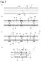
- FIG. 7 is an explanatory diagram of a process of forming a mask continuum to obtain individual pieces of the mask.
- FIG. 8 is an explanatory diagram of a process of forming a connecting member.
- FIG. 9 is an explanatory diagram of a process of forming the first and second extension portion continuums.
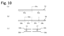
- FIG. 10 is an explanatory diagram of a process of forming the first and second extension portion continuums.
- FIG. 11 is a plan view of the mask.
- FIG. 12 is an explanatory diagram of a mask manufacturing process. (Conventional example 1)
- Example 1 The mask of Example 1 and the manufacturing method thereof will be described with reference to FIGS. 1 to 8.
- FIG. 1 is a front view of the unused mask 10 as viewed from the non-skin surface side.
- FIG. 2 is a rear view of the unused mask 10 as viewed from the skin surface side.
- FIG. 3A is a schematic diagram conceptually showing the configuration of a cross section cut along the line AA of FIG.
- FIG. 3B is a schematic diagram conceptually showing the configuration of a cross section cut along the line BB of FIG.
- FIG. 3C is a schematic diagram conceptually showing the configuration of a cross section cut along the line CC of FIG.
- FIG. 4A is a front view of the mask 10 in a used state as viewed from the non-skin surface side.
- FIG. 4B is a schematic diagram conceptually showing the configuration of a cross section cut along the XX line of FIG. 4A.
- the first and second ear hook portions 11a and 11b are arranged on the non-skin surface 12s of the mask main body 12 in an unused state. As shown in FIG. 4, when the mask 10 is in use, the first and second ear hook portions 11a and 11b are separated.
- the mask body 12 has first and second peripheral edges 12a and 12b extending in the left-right direction (that is, the first direction 10x) of the mask 10 and the vertical direction of the mask 10. It has third and fourth peripheral edges 12c, 12d extending in (ie, a second direction 10y intersecting the first direction 10x).
- the mask body 12 is configured by using, for example, a composite sheet in which a filter sheet is laminated between two non-woven fabric sheets.
- the composite sheet is folded in a fold shape so that a plurality of folding lines 12x, 12y extending in the first direction 10x are arranged so as to be displaced in the second direction 10y, and heat-sealed (heat welding, heat fusion). ), Ultrasonic seal (ultrasonic welding, ultrasonic welding), etc., to make the main body joints 12m, 12n, 12u, 12v, 12w (see FIG. 2) along the first to fourth peripheral edges 12a to 12d. It is formed.
- the layers are joined to each other and integrated at the main body joints 12m, 12n, 12u, 12v, 12w.
- a wire-shaped fit member 11 that is plastically deformable is arranged so as to extend along the first peripheral edge 12a.
- the fit member 11 is surrounded by the main body joints 12m and 12w.
- the mask body 12 widens the distance between the first and second peripheral edges 12a and 12b near the center of the first direction 10x, unfolds the folded folds of the mask body 12, and causes the mask body 12 to expand. Is made into a hemispherical three-dimensional shape, and the fitting member 11 is deformed along the raised shape of the nose so as to be brought into close contact with the face.
- the mask body 12 may be appropriately configured by using an appropriate sheet.
- the mask body 12 may be configured with only one sheet.
- the sheet constituting the mask body 12 may not be folded.
- the first ear hook portion 11a extends in the first and second extending portions 14a and 16a extending in the first direction 10x with a distance from each other in the second direction 10y, and extends in the second direction 10y. It has a first connecting portion 18a that is present.
- the first extending portion 14a extends along the first peripheral edge 12a of the mask body 12, and the second extending portion 16a extends along the second peripheral edge 12b of the mask body 12.
- One end portion 14p, 16p of each of the first and second extension portions 14a, 16a is joined to the first side edge portion 12p adjacent to the third peripheral edge 12c of the mask body 12 by the first side edge joint. It is joined via the portion 22a.
- a first connecting portion 18a is joined to the other end portions 14s and 16s of the first and second extending portions 14a and 16a via a first central joining portion 20a.
- the first connecting portion 18a is separate from the first and second extending portions 14a and 16a.
- the second ear hook portion 11b extends in the second direction 10y with the third and fourth extending portions 14b and 16b extending in the first direction 10x at intervals from each other in the second direction 10y. It has a second connecting portion 18b that is present.
- the third extension 14c extends along the first peripheral edge 12a of the mask body 12, and the fourth extension 14d extends along the second peripheral edge 12b of the mask body 12.
- One end portion 14q, 16q of each of the third and fourth extension portions 14c, 16d is joined to the second side edge portion 12q adjacent to the fourth peripheral edge 12d of the mask body 12 with a second side edge. It is joined via the portion 22b.
- a second connecting portion 18b is joined to the other end portions 14t and 16t of the third and fourth extending portions 14c and 16d, respectively, via a second central joining portion 20b.
- the second connecting portion 18b is separate from the first and second extending portions 14b and 16b.
- the first and second side edge joints 22a and 22b and the first and second central joints 20a and 20b are formed by an ultrasonic seal or a heat seal.
- the first and second ear hook portions 11a and 11b are composed of a first extending member 14, a second extending member 16, and a connecting member 18, which are separate from each other, and are the first of the mask main body 12. They are separably connected at the center of the direction 10x.
- the first extension member 14 forms a first extension portion 14a of the first ear hook portion 11a and a third extension portion 14b of the second ear hook portion 11b, and the first and third extension members 14 form.
- the other ends 14s, 14t of the extending portions 14a, 14b of the mask body 12 are configured to be separably connected at the center of the mask body 12 in the first direction 10x.
- the second extension member 16 forms a second extension portion 16a of the first ear hook portion 11a and a fourth extension portion 16b of the second ear hook portion 11b, and the second and second extension members 16 form.
- the other ends 16s, 16t of the extension portions 16a, 16b of 4 are configured to be separably connected at the center of the mask body 12 in the first direction 10x.
- first and second extension members 14, 16 were folded back along a folding line 50x, 52x between a pair of side edges 50s, 50t; 52s, 52t.
- elastic members 15 and 17 that can be expanded and contracted in the first direction 10x are sandwiched between two non-woven fabric sheets as in the second modification described later. It may be a non-woven fabric.
- 1 and 2 show a case where the side edges 50t and 52t of the extending members 14 and 16 are arranged so as to coincide with the peripheral edges 12a and 12b of the mask body 12.
- the side edges 50t and 52t of the extending members 14 and 16 may protrude to the outside of the mask body 12, and the side edges 50t and 52t of the extending members 14 and 16 are the peripheral edges 12a of the mask body 12. It may be located inside 12b.
- the non-woven fabric sheets 50 and 52 and the elastic members 15 and 17 are a part of the plurality of first and second side edge joints 22a and 22b and the plurality of first and second central joints 20a and 20b. Some of them are joined to each other. That is, the elastic members 15 and 17 are joined to the non-woven fabric sheets 50 and 52 at both ends of the extending portions 14a and 14b; 16a and 16b.
- the elastic members 15 and 17 are rubber threads, elastic films, and the like. Each of the elastic members 15 and 17 may be a plurality of elastic members, for example, a plurality of rubber threads.
- the connecting member 18 forms a first connecting portion 18a of the first ear hook portion 11a and a second connecting portion 18b of the second ear hook portion 11b, and the first and second connecting portions 18a,
- the 18b is configured to be separably connected at the center of the mask body 12 in the first direction 10x. That is, the side edges 18m and 18n (see FIG. 4) of the first and second connecting portions 18a and 18b that are adjacent to each other are connected to each other.
- the side edges 18u and 18v of the first and second connecting portions 18a and 18b on opposite sides are curved so as to approach each other in the intermediate portion in the second direction 10y.
- the connecting member 18 is formed with a perforation 30 and a slit 32 extending in the second direction 10y at the center of the mask body 12 in the first direction 10x.
- the perforations 30 are a plurality of cuts penetrating between the main surfaces of the connecting member 18, and are formed in the intermediate portion of the connecting member 18 in the second direction 10y.
- the slits 32 are formed on both sides of the perforation 30 so as to be aligned with the perforation 30.
- the slit 32 may be formed so as to penetrate between the main surfaces of the connecting member 18, or may be formed from one main surface of the connecting member 18 to the front of the other main surface.
- the cuts can be formed as appropriate.
- perforations 30 may be formed on both sides of the slit 32 so as to be aligned with the slit 32, or only one of the perforations 30 and the slit 32 is formed. You may.
- the first and second connecting portions 18a and 18b are the second when the unused mask 10 is viewed from the direction perpendicular to the first and second directions 10x and 10y.
- the ends 18p, 18q; 18s, 18t on both sides in the direction of 10y project from the mask body 12.
- the first and second connecting portions 18a and 18b can be easily separated from the mask main body 12, and the first and second ear hook portions 11a and 11b can be easily separated. Even if only one of the ends 18p, 18q or 18s, 18t protrudes from the mask body 12, the first and second ear hooks 11a and 11b can be easily separated.
- a configuration in which both ends 18p, 18q; 18s, 18t of the first and second connecting portions 18a and 18b do not protrude from the mask main body 12 may be used.
- the connecting member 18 when the mask 10 is in an unused state, the connecting member 18 is arranged on the side of the first and second extending members 14 and 16 opposite to the mask main body 12, and the first And there is no space between the second extension members 14, 16 and the mask body 12.
- the connecting member 18 includes ends 14s and 14t of the first and third extension portions 14a and 14b adjacent to each other and ends 16s and 16t of the second and fourth extension portions 16a and 16b adjacent to each other. Since it covers, the appearance near the center of the first direction 10x is simplified. However, when the mask 10 is in an unused state, the connecting member 18 may be arranged on the mask main body 12 side of the first and second extending members 14 and 16.
- the first and second ear hooks 11a and 11b are separated. That is, the connecting member 18 is cut along the perforation 30 and the slit 32 to separate the first and second connecting portions 18a and 18b, and the first extending member 14 is cut to cut the first and third connecting members 18. The extension portions 14a and 14b of the above are separated, and the second extension member 16 is cut to separate the second and fourth extension portions 16a and 16b.
- the first and second ear hook portions 11a and 11b are separated, and the mask main body 12 is deployed on opposite sides toward the outside in the first direction 10x.
- the first and second ear hooks 11a and 11b are folded back on the mask body 12.
- the first and second ear hooks 11a, 11b are surrounded by the first and third extension parts 14a, 14b, the second and fourth extension parts 16a, 16b, and the connection parts 18a, 18b.
- the first and second ear hook holes 13a and 13b are partitioned, and ears are inserted into the first and second ear hook holes 13a and 13b.
- the side edges 18u and 18v of the first and second ear hooks 11a and 11b along the wearer's ear are curved, so that the side edges 18u and 18v are not curved and are straight.
- the wearing feeling of the mask 10 is improved as compared with the case of the shape.
- the mask 10 In the unused state of the mask 10, since the first and second ear hook portions 11a and 11b are arranged on the non-skin surface 12s side of the mask body 12, the mask 10 does not touch the skin surface 12t of the mask body 12.
- the mask 10 can be attached and is hygienic.
- the first and second ear hook portions 11a and 11b may be arranged on the skin surface 12t side of the mask body 12.
- the first and second extension portions 14a and 16a and the first connection portion 18a are separate bodies, and the third and fourth extension portions 14b and 16b and the second connection portion 18b Is a separate body, so that the portions forming the first and third extension portions 14a and 14b and the portions forming the second and fourth extension portions 16a and 16b are continuous, respectively.
- the ear hook continuum 56 (described later) for forming the first and second ear hooks 11a and 11b can be configured. Since the ear hook continuous body 56 (described later) configured in this way can be conveyed at high speed and does not interfere with the production of the mask 10 at high speed, the mask 10 can be manufactured at high speed. As a result, the number of masks 10 manufactured per unit time can be increased.
- first and second extension portions 14a and 16a and the first connection portion 18a are separate bodies, and the third and fourth extension portions 14b and 16b and the second connection portion 18b are separate. Since it is a body, it is not necessary to cut off the entire portion of the ear hook holes 13a and 13b from the material. Therefore, the waste of the material can be reduced.
- FIG. 5 is an explanatory diagram of a process of forming the first and second extension portion continuums 51 and 53.
- FIG. 6 is an explanatory diagram of a process of forming the ear hook continuum 56.
- FIG. 7 is an explanatory diagram of a process of forming a mask continuum 60 to obtain individual pieces of the mask 10.
- the method for manufacturing the mask 10 generally includes the first to fifth steps.
- the mask body continuum 58 having the first and second side edges 58p, 58q parallel to each other is attached to the first and second side edges 58p, 58p. It is conveyed in the direction in which 58q extends.
- the first side edge 58p forms the first peripheral edge 12a of the mask body 12
- the second side edge 58q forms the second peripheral edge 12b of the mask body 12.
- the mask body continuous body 58 is folded into a fold shape so that the fold line 58x extends in the transport direction while transporting a continuous sheet of one layer or a plurality of layers, and then appropriately by ultrasonic sealing, heat sealing, or the like.
- the positions are joined and integrated to form a main body joint portion 12m, 12n, 12u, 12v, 12w (see FIGS. 1, 2, and 4, not shown in FIG. 7).
- the first and second extending portion continuums 51 and 53 which are continuous in one direction, are parallel to each other and at predetermined intervals, respectively. Transport at the same speed in continuous directions.
- first and second extension members 51 and 53 are cut in a direction intersecting their respective continuous directions, one end 14p of the first and second extension members 14, 16 16p and the other ends 14q, 16q of the other first and second extension members 14, 16 are formed.
- the first and second extension continuous bodies 51 and 53 are manufactured using one non-woven sheet 54, for example, as shown in FIG.
- a strip-shaped non-woven fabric sheet 54 having a pair of main surfaces 54s and 54t and a pair of side edges 54p and 54q parallel to each other is formed in a direction in which the side edges 54p and 54q are continuous.
- the first and second elastic members 15 and 17 in the stretched state shown by the alternate long and short dash line are arranged on one main surface 54s of the conveyed nonwoven fabric sheet 54. Then, it is conveyed together with the non-woven fabric sheet 54.
- the first and second elastic members 15 and 17 are spaced apart from each other and arranged in parallel with the conveying direction of the non-woven fabric sheet 54.
- the elastic members 15 and 17 are rubber threads, elastic films, and the like.
- Each of the elastic members 15 and 17 may be a plurality of elastic members, for example, a plurality of rubber threads.
- the non-woven fabric sheet 54 is folded so that the side edges 54p and 54q of the non-woven fabric sheet 54 are arranged on one main surface 54s of the non-woven fabric sheet 54 at intervals from each other.
- the elastic members 15 and 17 are folded back at 54 m and 54 n to form a common continuum 55 sandwiched between the non-woven fabric sheets 54.
- the first elastic member 15 is included by cutting between the side edges 54p and 54q of the non-woven fabric sheet 54 of the common continuum 55 in the transport direction. It is divided into an extension portion continuum 51 and a second extension portion continuum 53 including a second elastic member 17.
- FIG. 5 (d) the positions of the first and second extending portion continuums 51 and 53 are exchanged so that the folding lines 54m and 54n face each other, and the first and second extending portions are replaced with each other.
- the extending portion continuums 51 and 53 are conveyed in parallel with each other at the same speed with a predetermined interval.
- first and second extension continuations 51 and 53 it is efficient to form the first and second extension continuations 51 and 53 by forming and dividing the common continuum 55.
- first and second extension continuums 51 and 53 may be formed separately.
- the plurality of connecting members 18 are straddled between the first and second extending portion continuums 51 and 53 which are conveyed in parallel with each other.
- the first and second extension continuums 51, 53 are provided with a predetermined interval in the direction of being conveyed, and the first and second extension continuums 51, 53 are ultrasonically sealed or heat-sealed.
- the ear hook continuum 56 is formed.
- the first and second central joining portions 20a and 20b are formed.
- the non-woven fabric sheet 54 constituting the first and second extending portion continuums 51 and 53 and the first and second elastic members 15 and 17
- the non-woven fabric sheet 54 is joined to the connecting member 18 to each other.
- a portion to be formed and a portion where the non-woven fabric sheet 54, the first or second elastic member 15 or 17, and the connecting member 18 are joined to each other are formed.
- FIG. 8 is an explanatory diagram of a process of forming the connecting member 18. While transporting the strip-shaped continuous sheet 70 shown in FIG. 8 (a) in the longitudinal direction, an excess portion is cut off to form a pair of side edges 72 and 74 and a hollow hole 76 as shown in FIG. 8 (b). .. Next, as shown by the chain line 60x in FIG. 8 (b), the continuous sheet 70 is cut at the position where the hollow hole 76 is bisected, and as shown in FIG. 8 (c), individual pieces of the connecting member 18 are obtained.
- the side edges 18u and 18v of the connecting member 18 are formed by the peripheral edges of the hollow holes 76, they are cut into a curved shape so as to approach each other in the intermediate portion.
- the continuous sheet 70 is sequentially cut into strips and the cut connecting members 18 are conveyed at a predetermined interval, the first and second extension continuous bodies 51 and 53 are joined at a predetermined interval.
- the formation of the continuous sheet can be synchronized with the formation of the ear hook continuum 56.
- slits 32 are formed on both sides of the perforation 30.
- the slit 32 may be formed only in the connecting member 18, or may be formed in the connecting member 18 and the first and second extending portion continuums 51 and 53.
- the slit 32 may be a notch that penetrates the connecting member 18 or the first and second extension continuous bodies 51 and 53, or a notch that is formed halfway without penetrating.
- the perforation 30 and the slit 32 are formed so that both sides of the perforation 30 and the slit 32 are connected to each other.
- the first and second ear hooks 11a and 11b can be easily separated along the perforations 30 and the slits 32.
- the mask may be manufactured without forming the perforations 30 and the slits 32.
- the connected first and second ear hooks 11a and 11b are cut using, for example, a cutter or scissors to separate the first and second ear hooks 11a and 11b.
- the first and second extension portion continuums 51 and 53 of the ear hook continuum 56 are contracted in the transport direction to release the stretched states of the elastic members 15 and 17. do. As a result, the distance L between the connecting members 18 adjacent to each other is shortened. Since the first and second extension portion continuums 51 and 53 have elastic elasticity, the first and second extension portion continuums 51 and 53 can be contracted.
- the ear hook continuous body 56 and the mask body continuous body 58 which are conveyed to each other, are brought together with the first extended portion continuous body 56 of the ear hook continuous body 56.
- the body 51 is along the first side edge 58p of the mask body continuum 58
- the second extension continuum 53 of the ear hook continuum 56 is on the second side edge 58q of the mask body continuum 58.
- the first and second extension part continuums 51 of the ear hook part continuum 56 are overlapped with each other so as to be along each other, and as shown in FIG. 7C, in the middle between the connecting members 18 adjacent to each other.
- the mask continuum 60 is formed by joining the 53 and the mask main body continuum 58 to each other by an ultrasonic seal, a heat seal, or the like. By the joining at this time, the first and second side edge joint portions 22a and 22b are formed. Specifically, of the non-woven fabric sheet 54 and the first and second elastic members 15 and 17 constituting the first and second extending portion continuous bodies 51 and 53 of the ear hook portion continuous body 56, only the non-woven fabric sheet 54 is used. A portion where the mask body continuum 58 is joined to each other and a portion where the non-woven fabric sheet 54, the first or second elastic member 15 or 17, and the mask body continuum 58 are joined to each other are formed.
- the side edges 51x and 53x of the extension portion continuation bodies 51 and 53 on opposite sides of each other may coincide with the side edges 58p, 58q (see FIG. 7A) of the mask body continuum 58, may protrude outside the mask body continuum 58, or may protrude outside the mask body continuum 58. It may be located inside the side edges 58p and 58q of the continuum 58.
- the conveyed mask continuum 60 is placed in a direction (for example, orthogonal directions) intersecting the direction in which the mask continuum 60 is conveyed, as shown by the chain line 60x in FIG. 7 (c). It is cut to obtain a piece of mask 10 as shown in FIG. 7 (d).
- the third and fourth peripheral edges 12c and 12d of the mask body 12 are formed.
- the first and second extension members 14 and 16 of the mask main body 12 are formed by cutting the first and second extension continuous bodies 51 and 53 of the mask continuum 60.
- the elastic first and second extension members 14 and 16 are released. It is possible to obtain a mask 10 in a flat state arranged along the mask body 12.
- the ear hook continuous body 56 can be conveyed at high speed because the first and second extending portion continuous bodies 51 and 53 are continuous, and the mask 10 can be conveyed at high speed. Can be manufactured. Further, since the ear hook continuous body 56 can be formed without cutting off the portion corresponding to the entire ear hook holes 13a and 13b, waste of the material can be reduced.
- the first and second extension portion continuums 51 and 53 are stretched in the direction in which the first and second extension portion continuums 51 and 53 are conveyed before the fourth step. Therefore, elasticity may be imparted in the transport direction of the first and second extension continuous bodies 51 and 53.
- the stretching process is performed by transporting the first and second extending portion continuous bodies 51, 53 or the ear hook continuous bodies 56 while sandwiching them between a pair of rolls having an uneven outer peripheral surface that meshes with each other.
- FIGS. 9 and 10 are explanatory views showing a modified example 1 of the step of forming the first and second extending portion continuums, and are schematic views of a cross section cut in the width direction.
- the first and second elastic members 15 and 17 are arranged on one side edge 62q side of one non-woven fabric sheet 62, and then as shown in FIG. 9 (b). , The other side edge 62p side of the non-woven fabric sheet 62 is folded back, the first and second elastic members 15 and 17 are sandwiched between the non-woven fabric sheets 62, and as shown by the chain wire 62y, the first and second elastic members The gap between 15 and 17 may be cut to form the first and second extension continuums.
- the first and second elastic members 15 and 17 are sandwiched between the two non-woven fabric sheets 64a and 64b, and the first and second elastic members 15 are placed at the positions indicated by the chain wires 64x. , 17 may be cut to form a first and second extension continuum.
- two non-woven fabric sheets 64a and 64b may be used in which one non-woven fabric continuous web 64 is cut and divided in the longitudinal direction at the position indicated by the chain line 64y.
- the elastic member 66 is sandwiched between one non-woven fabric sheet 62 in which one side edge 62p side and the other side edge 62q side are folded back, and the non-woven fabric sheet is at the position indicated by the chain line 62y.
- the 62 and the elastic member 66 may be cut and divided to form a first and second extension continuous body.
- the elastic member 66 is sandwiched between one non-woven fabric sheet 62 in which one side edge 62q side is folded back to the other side edge 62p side, and the non-woven fabric sheet 62 is located at the position indicated by the chain wire 62x. And the elastic member 66 may be cut and divided to form a first and second extension continuous body.
- the elastic member 66 is sandwiched between the two non-woven fabric sheets 64a and 64b, and the non-woven fabric sheets 64a and 64b and the elastic member 66 are cut and divided at the position indicated by the chain wire 64x.
- the first and second extension continuums may be formed.
- two non-woven fabric sheets 64a and 64b may be used in which one non-woven fabric continuous web 64 is cut and divided in the longitudinal direction at the position indicated by the chain line 64y.
- one non-woven fabric continuous web 64 is cut in the longitudinal direction at three locations indicated by chain lines 64z to form four non-woven fabric sheets 64k, and then FIG. 10 (b).
- the first and second extended portion continuums may be formed by sandwiching the first and second elastic members 15 and 17 between two sheets 64k each.
- ⁇ Modification 2> When manufacturing a mask in which thread rubber is arranged as elastic members 15 and 17 on the extension members 14 and 16 constituting the extension portions 14a and 14b; 16a and 16b, the thread rubber is in an stretched state. , With the thread rubber sandwiched between the non-woven fabric sheets, the thread rubber and the non-woven fabric sheet are fused to each other intermittently in the transport direction by ultrasonic waves or heat, and the first and second extension continuous bodies 551 , 53 may be formed. In this case, the rubber thread and the non-woven fabric sheet do not have to be joined to each other at the first and second side edge joints 22a and 22b and the first and second central joints 20a and 20b.
- the mask and mask manufacturing method described above can reduce the waste of materials and can manufacture masks at high speed.
- the present invention is not limited to the above embodiment, and can be implemented with various modifications.
- the mask of the present invention may be manufactured by a method other than the above-mentioned method.
- the mask body may have a shape other than a rectangle.
- the angle formed by the first and second peripheral edges of the mask body and the third and fourth peripheral edges may be an acute angle or an obtuse angle.
- the peripheral edge of the mask body may be curved, or may have a shape that repeatedly bends and / or curves.
Abstract
Description
を備える。前記第1の耳掛け部は、(i)それぞれの一方の端部が前記第1の側縁部に接合され、前記第2の方向に互いに間隔を設けて、前記第1の周縁又は前記第2の周縁に沿って前記第1の方向に延在する第1及び第2の延出部と、(ii)前記第1及び第2の延出部それぞれの他方の端部に接合され、前記第2の方向に延在する、前記第1及び第2の延出部とは別体の第1の接続部と、を有する。前記第2の耳掛け部は、(i)それぞれの一方の端部が前記第2の側縁部に接合され、前記第2の方向に互いに間隔を設けて、前記第1の周縁又は前記第2の周縁に沿って前記第1の方向に延在する第3及び第4の延出部と、(ii)前記第3及び第4の延出部それぞれの他方の端部に接合され、前記第2の方向に延在する、前記第3及び第4の延出部とは別体の第2の接続部と、を有する。前記第1の耳掛け部の前記第1及び第2の延出部と前記第1の接続部とに囲まれた第1の耳掛け穴が区画される。前記第2の耳掛け部の前記第3及び第4の延出部と前記第2の接続部とに囲まれた第2の耳掛け穴が区画される。 The mask is (a) a mask having first and second peripheral edges extending in a first direction and third and fourth peripheral edges extending in a second direction intersecting the first direction. The main body, (b) a first ear hook portion joined to a first side edge portion adjacent to the third peripheral edge of the mask main body, and (c) adjacent to the fourth peripheral edge of the mask main body. A second ear hook joined to the second side edge
To be equipped. In the first ear hook portion, (i) one end portion thereof is joined to the first side edge portion, and the first peripheral edge portion or the first peripheral portion is provided so as to be spaced from each other in the second direction. The first and second extension portions extending along the peripheral edge of the second in the first direction and (ii) the other end of each of the first and second extension portions are joined to the above. It has a first connecting portion that extends in the second direction and is separate from the first and second extending portions. In the second ear hook portion, (i) one end portion thereof is joined to the second side edge portion, and the second peripheral edge portion or the first peripheral portion or the first peripheral portion is provided so as to be spaced from each other in the second direction. It is joined to the third and fourth extension portions extending along the peripheral edge of the second in the first direction and (ii) the other end of each of the third and fourth extension portions. It has a second connecting portion that extends in the second direction and is separate from the third and fourth extending portions. A first ear hook hole surrounded by the first and second extension portions of the first ear hook portion and the first connection portion is partitioned. A second ear hook hole surrounded by the third and fourth extension portions of the second ear hook portion and the second connection portion is partitioned.
10x 第1の方向
10y 第2の方向
11a,11b 耳掛け部
12 マスク本体
12a~12d 周縁
12p,12q 側縁部
12s 非肌面
12t 肌面
13a,13b 耳掛け穴
14 第1の延出部材(部材)
14a 第1の延出部
14b 第3の延出部
14p,14q 端部
14s,14t 端部
15 第1の弾性部材
16 第2の延出部材(部材)
16a 第2の延出部
16b 第4の延出部
16p,16q 一方の端部
16s,16t 他方の端部
17 第2の弾性部材
18 接続部材
18a,18b 接続部
18p,18q 同じ側の端部
18s,18t 同じ側の端部
30 ミシン目(切り込み)
32 スリット(切り込み)
50 不織布シート
51 第1の延出部連続体
52 不織布シート
53 第2の延出部連続体
55 共通連続体
56 耳掛け部連続体
58 マスク本体連続体
58p,58q 側縁
60 マスク連続体 10
14a
16a
32 slit (notch)
50
Claims (17)
- 第1の方向に延在する第1及び第2の周縁と、前記第1の方向と交差する第2の方向に延在する第3及び第4の周縁とを有するマスク本体と、
前記マスク本体の前記第3の周縁に隣接する第1の側縁部に接合された第1の耳掛け部と、
前記マスク本体の前記第4の周縁に隣接する第2の側縁部に接合された第2の耳掛け部と、
を備えるマスクであって、
前記第1の耳掛け部は、
それぞれの一方の端部が前記第1の側縁部に接合され、前記第2の方向に互いに間隔を設けて、前記第1の周縁又は前記第2の周縁に沿って前記第1の方向に延在する第1及び第2の延出部と、
前記第1及び第2の延出部それぞれの他方の端部に接合され、前記第2の方向に延在する、前記第1及び第2の延出部とは別体の第1の接続部と、
を有し、
前記第2の耳掛け部は、
それぞれの一方の端部が前記第2の側縁部に接合され、前記第2の方向に互いに間隔を設けて、前記第1の周縁又は前記第2の周縁に沿って前記第1の方向に延在する第3及び第4の延出部と、
前記第3及び第4の延出部それぞれの他方の端部に接合され、前記第2の方向に延在する、前記第3及び第4の延出部とは別体の第2の接続部と、
を有し、
前記第1の耳掛け部の前記第1及び第2の延出部と前記第1の接続部とに囲まれた第1の耳掛け穴が区画され、
前記第2の耳掛け部の前記第3及び第4の延出部と前記第2の接続部とに囲まれた第2の耳掛け穴が区画される、マスク。 A mask body having first and second peripheral edges extending in a first direction and third and fourth peripheral edges extending in a second direction intersecting the first direction.
A first ear hook portion joined to a first side edge portion adjacent to the third peripheral edge of the mask body, and a first ear hook portion.
A second ear hook portion joined to a second side edge portion adjacent to the fourth peripheral edge of the mask body, and a second ear hook portion.
It is a mask equipped with
The first ear hook portion is
One end of each is joined to the first lateral edge, spaced from each other in the second direction, in the first direction along the first or second edge. The extending first and second extension parts,
A first connecting portion that is joined to the other end of each of the first and second extending portions and extends in the second direction, which is separate from the first and second extending portions. When,
Have,
The second ear hook is
One end of each is joined to the second side edge and spaced from each other in the second direction in the first direction along the first or second edge. With the extending 3rd and 4th extension parts,
A second connection portion that is joined to the other end of each of the third and fourth extension portions and extends in the second direction, which is separate from the third and fourth extension portions. When,
Have,
A first ear hook hole surrounded by the first and second extension portions of the first ear hook portion and the first connection portion is partitioned.
A mask in which a second ear hook hole surrounded by the third and fourth extension portions of the second ear hook portion and the second connection portion is partitioned. - 前記マスクは、未使用状態において、
前記第1の耳掛け部の前記第1の延出部の前記他方の端部と、前記第2の耳掛け部の前記第3の延出部の前記他方の端部とが、前記マスク本体の前記第1の方向の中央において分離可能に繋がっており、
前記第1の耳掛け部の前記第2の延出部の前記他方の端部と、前記第2の耳掛け部の前記第4の延出部の前記他方の端部とが、前記マスク本体の前記第1の方向の中央において分離可能に繋がっており、
前記第1の耳掛け部の前記第1の接続部と、前記第2の耳掛け部の前記第2の接続部とが、前記マスク本体の前記第1の方向の中央において分離可能に繋がっており、
前記マスクは、使用する際に、前記第1及び第2の耳掛け部が、前記マスク本体の前記第1の方向の中央において分離される、請求項1に記載のマスク。 The mask is in an unused state.
The other end of the first extension of the first ear hook and the other end of the third extension of the second ear hook are the mask body. In the center of the first direction, they are separably connected.
The other end of the second extension of the first ear hook and the other end of the fourth extension of the second ear hook are the mask body. In the center of the first direction, they are separably connected.
The first connection portion of the first ear hook portion and the second connection portion of the second ear hook portion are separably connected at the center of the mask body in the first direction. Ori,
The mask according to claim 1, wherein when used, the first and second ear hooks are separated at the center of the mask body in the first direction. - 前記マスクは、未使用状態において、前記第1及び第2の耳掛け部が、前記マスク本体の非肌面側に配置されている、請求項1又は2に記載のマスク。 The mask according to claim 1 or 2, wherein the first and second ear hooks are arranged on the non-skin surface side of the mask body in an unused state.
- 前記マスクは、未使用状態において、前記第1及び第2の方向に垂直な第3の方向から見ると、前記第1の耳掛け部の前記第1の接続部と前記第2の耳掛け部の前記第2の接続部との、前記第2の方向の同じ側の端部が、前記マスク本体から突出している、請求項1乃至3のいずれか一つに記載のマスク。 When the mask is in an unused state and viewed from a third direction perpendicular to the first and second directions, the first connection portion of the first ear hook portion and the second ear hook portion are used. The mask according to any one of claims 1 to 3, wherein the end portion on the same side in the second direction with the second connecting portion of the mask protrudes from the mask body.
- 前記マスクは、未使用状態において、
前記第1の耳掛け部の前記第1の接続部が、前記第1の耳掛け部の前記第1及び第2の延出部の前記マスク本体とは反対側に配置され、
前記第2の耳掛け部の前記第2の接続部が、前記第2の耳掛け部の前記第3及び第4の延出部の前記マスク本体とは反対側に配置されている、請求項1乃至4のいずれか一つに記載のマスク。 The mask is in an unused state.
The first connection portion of the first ear hook portion is arranged on the side opposite to the mask main body of the first and second extension portions of the first ear hook portion.
The second connection portion of the second ear hook portion is arranged on the opposite side of the third and fourth extension portions of the second ear hook portion to the mask main body. The mask according to any one of 1 to 4. - 前記マスクは、未使用状態において、前記マスク本体の前記第1の方向の中央において前記第1及び第2の耳掛け部が互いに繋がっており、
前記マスクは、使用状態において、前記第1及び第2の耳掛け部が、前記マスク本体の前記第1の方向の前記中央で分離され、前記マスク本体の前記第1の方向の外側に折り返される、請求項1乃至5のいずれか一つに記載のマスク。 In the unused state of the mask, the first and second ear hooks are connected to each other at the center of the mask body in the first direction.
In the mask, the first and second ear hooks are separated at the center of the mask body in the first direction and folded back to the outside of the mask body in the first direction. , The mask according to any one of claims 1 to 5. - 前記第1の耳掛け部の前記第1及び第2の延出部と、前記第2の耳掛け部の前記第3及び第4の延出部とは、それぞれ、2枚の不織布シートの間又は折り返された1枚の不織布シートの間に、前記第1の方向に伸縮可能な弾性部材が挟み込まれた部材で構成される、請求項1乃至6のいずれか一つに記載にマスク。 The first and second extension portions of the first ear hook portion and the third and fourth extension portions of the second ear hook portion are between two non-woven fabric sheets, respectively. The mask according to any one of claims 1 to 6, wherein the elastic member that can be expanded and contracted in the first direction is sandwiched between one folded non-woven fabric sheet.
- 第1の方向に延在する第1及び第2の周縁と、前記第1の方向と交差する第2の方向に延在する第3及び第4の周縁とを有するマスク本体と、
前記マスク本体の前記第3の周縁に隣接する第1の側縁部に接合された第1の耳掛け部と、
前記マスク本体の前記第4の周縁に隣接する第2の側縁部に接合された第2の耳掛け部と、
を備え、
前記第1及び第2の耳掛け部が、
前記第2の方向に互いに間隔を設けて前記第1の周縁又は前記第2の周縁に沿って延在し、それぞれの一方の端部が前記マスク本体の前記第1の側縁部に接合され、それぞれの他方の端部が前記マスク本体の前記第2の側縁部に接合された第1及び第2の延出部材と、
前記マスク本体の前記第1の方向の中央において前記第2の方向に延在し、前記第1及び第2の延出部材に接合された、前記第1及び第2の延出部材とは別体の接続部材と、
によって構成され、
前記第1及び第2の延出部材と前記接続部材とに囲まれた第1及び第2の耳掛け穴が区画される、マスクの製造方法であって、
互いに平行である第1及び第2の側縁を有し、前記第1の側縁により前記マスク本体の前記第1の周縁が形成され、前記第2の側縁により前記マスク本体の前記第2の周縁が形成され、前記第1及び第2の側縁と交差する方向に切断すると、前記マスク本体の前記第3の周縁と、他の前記マスク本体の前記第4の周縁とが同時に形成されるマスク本体連続体を、前記第1及び第2の側縁が延在する方向に搬送する第1の工程と、
それぞれ一方向に連続し、前記一方向と交差する方向に切断すると、前記第1及び第2の延出部材の前記一方の端部と、他の前記第1及び第2の延出部材の前記他方の端部とが同時に形成される第1及び第2の延出部連続体を、互いに平行かつ所定の間隔を設けて、それぞれ前記一方向に搬送する第2の工程と、
搬送されている前記第1及び第2の延出部連続体の間を跨ぐように、複数の前記接続部材を、前記第1及び第2の延出部連続体が搬送される方向に所定の間隔を設けて、前記第1及び第2の延出部連続体に接合することによって、耳掛け部連続体を形成する第3の工程と、
互いに搬送されている前記耳掛け部連続体と前記マスク本体連続体とを、前記耳掛け部連続体の前記第1の延出部連続体が前記マスク本体連続体の前記第1の側縁に沿い、前記耳掛け部連続体の前記第2の延出部連続体が前記マスク本体連続体の前記第2の側縁に沿うように、互いに重ね合わせ、互いに隣り合う前記接続部材の間の中間において、前記耳掛け部連続体の前記第1及び第2の延出部連続体と前記マスク本体連続体とを互いに接合することによって、マスク連続体を形成する第4の工程と、
搬送されている前記マスク連続体を、前記マスク連続体が搬送される方向と交差する方向に切断して、前記マスクの個片を得る第5の工程と、
を備えた、マスクの製造方法。 A mask body having first and second peripheral edges extending in a first direction and third and fourth peripheral edges extending in a second direction intersecting the first direction.
A first ear hook portion joined to a first side edge portion adjacent to the third peripheral edge of the mask body, and a first ear hook portion.
A second ear hook portion joined to a second side edge portion adjacent to the fourth peripheral edge of the mask body, and a second ear hook portion.
With
The first and second ear hooks
It extends along the first peripheral edge or the second peripheral edge at intervals from each other in the second direction, and one end of each is joined to the first side edge portion of the mask body. , The first and second extending members, each of which has its other end joined to the second side edge of the mask body.
Separate from the first and second extension members extending in the second direction at the center of the mask body in the first direction and joined to the first and second extension members. With body connecting members
Consists of
A method for manufacturing a mask, wherein the first and second ear hook holes surrounded by the first and second extending members and the connecting member are partitioned.
It has first and second side edges that are parallel to each other, the first side edge forms the first peripheral edge of the mask body, and the second side edge forms the second edge of the mask body. When the peripheral edge of the mask body is formed and cut in a direction intersecting the first and second side edges, the third peripheral edge of the mask body and the fourth peripheral edge of the other mask body are simultaneously formed. The first step of transporting the continuous mask body in the direction in which the first and second side edges extend, and
When each is continuous in one direction and cut in a direction intersecting the one direction, the one end of the first and second extension members and the other one end of the first and second extension members are said to be the same. A second step of transporting the first and second extending portion continuums in which the other end portion is formed at the same time in one direction, parallel to each other and at a predetermined interval, respectively.
A plurality of the connecting members are connected in a direction in which the first and second extension continuums are conveyed so as to straddle between the first and second extension continuums being conveyed. A third step of forming the ear hook continuum by joining the first and second extension continuums at intervals, and
The ear hook continuous body and the mask body continuous body that are conveyed to each other are brought to the first side edge of the mask body continuous body by the first extending portion continuous body of the ear hook continuous body. Along, the second extension continuum of the ear hook continuum is overlapped with each other so as to be along the second side edge of the mask body continuum, and is intermediate between the connecting members adjacent to each other. In the fourth step of forming the mask continuum by joining the first and second extending portion continuums of the ear hook continuum and the mask body continuum to each other.
A fifth step of cutting the transported mask continuum in a direction intersecting the direction in which the mask continuum is transported to obtain individual pieces of the mask.
A method of manufacturing a mask. - 前記第3の工程において、弾性伸縮性を有する前記第1及び第2の延出部連続体が、前記第1及び第2の延出部連続体の搬送される方向に伸張している状態で搬送され、
前記第4の工程において、前記耳掛け部連続体の前記第1及び第2の延出部連続体が、前記第1及び第2の延出部連続体の搬送される前記方向に収縮している状態で搬送される、請求項8に記載のマスクの製造方法。 In the third step, in a state where the first and second extension continuums having elastic elasticity are extended in the direction in which the first and second extension continuums are conveyed. Transported,
In the fourth step, the first and second extension continuums of the ear hook continuum contract in the direction in which the first and second extension continuums are conveyed. The method for manufacturing a mask according to claim 8, wherein the mask is transported in a state of being in the state. - 前記第1の延出部連続体は、
前記第1の延出部連続体が搬送される前記方向に連続する2枚の不織布シートの間又は折り返された1枚の不織布シートと、
前記2枚の不織布シートの間又は折り返された前記1枚の不織布シートの間に挟み込まれ、前記第1の延出部連続体が搬送される前記方向に、伸縮可能かつ連続する第1の弾性部材と、
を有し、
前記第2の延出部連続体は、
前記第2の延出部連続体が搬送される前記方向に連続する他の2枚の不織布シートの間又は折り返された他の1枚の不織布シートと、
前記他の2枚の不織布シートの間又は折り返された前記他の1枚の不織布シートの間に挟み込まれ、前記第2の延出部連続体が搬送される前記方向に、伸縮可能かつ連続する第2の弾性部材と、
を有する、請求項8又は9に記載のマスクの製造方法。 The first extension continuum is
Between two continuous non-woven fabric sheets in the direction in which the first extension continuous body is conveyed or one folded non-woven fabric sheet,
A first elastic that is stretchable and continuous in the direction in which the first extending portion continuum is conveyed, sandwiched between the two non-woven fabric sheets or between the folded one non-woven fabric sheets. Members and
Have,
The second extension continuum is
Between the other two non-woven fabric sheets continuous in the direction in which the second extension continuous body is conveyed, or with another folded non-woven fabric sheet.
It is sandwiched between the other two non-woven fabric sheets or between the other folded non-woven fabric sheets, and is stretchable and continuous in the direction in which the second extension continuous body is conveyed. The second elastic member and
The method for producing a mask according to claim 8 or 9. - 前記第1の延出部連続体は、
前記第1の延出部連続体が搬送される前記方向に連続する2枚の不織布シートの間又は折り返された1枚の不織布シートと、
前記2枚の不織布シートの間又は折り返された前記1枚の不織布シートの間に挟み込まれ、前記第1の延出部連続体が搬送される前記方向に連続する第1の弾性部材と、
を有し、
前記第2の延出部連続体は、
前記第2の延出部連続体が搬送される前記方向に連続する他の2枚の不織布シートの間又は折り返された他の1枚の不織布シートと、
前記他の2枚の不織布シートの間又は折り返された前記他の1枚の不織布シートの間に挟み込まれ、前記第2の延出部連続体が搬送される前記方向に連続する第2の弾性部材と、
を有し、
前記第4の工程よりも前に、
前記第1の延出部連続体は、前記第1の延出部連続体が搬送される前記方向に延伸加工が施されて、前記第1の延出部連続体が搬送される前記方向に伸縮性を付与され、
前記第2の延出部連続体は、前記第2の延出部連続体が搬送される前記方向に延伸加工が施されて、前記第2の延出部連続体が搬送される前記方向に伸縮性を付与される、請求項8又は9に記載のマスクの製造方法。 The first extension continuum is
Between two continuous non-woven fabric sheets in the direction in which the first extension continuous body is conveyed or one folded non-woven fabric sheet,
A first elastic member sandwiched between the two non-woven fabric sheets or between the folded one non-woven fabric sheets and continuous in the direction in which the first extending portion continuum is conveyed.
Have,
The second extension continuum is
Between the other two non-woven fabric sheets continuous in the direction in which the second extension continuous body is conveyed, or with another folded non-woven fabric sheet.
A second elasticity that is sandwiched between the other two non-woven fabric sheets or between the other folded non-woven fabric sheets and is continuous in the direction in which the second extension continuous body is conveyed. Members and
Have,
Prior to the fourth step,
The first extension continuous body is stretched in the direction in which the first extension continuous body is conveyed, and in the direction in which the first extension continuous body is conveyed. Gives elasticity,
The second extension continuous body is stretched in the direction in which the second extension continuous body is conveyed, and in the direction in which the second extension continuous body is conveyed. The method for producing a mask according to claim 8 or 9, which is imparted with elasticity. - 前記第2の工程で搬送する前記第1及び第2の延出部連続体は、
連続する前記2枚の不織布シートの間、又は折り返され、折り線の方向に連続する1枚の不織布シートの間に、第1及び第2の弾性部材を、互いに間隔を設けて、前記2枚の不織布シート又は前記1枚の不織布シートの連続する方向に連続するように挟み込んで共通連続体を形成し、前記共通連続体を、前記第1の弾性部材を含む前記第1の延出部連続体と前記第2の弾性部材を含む前記第2の延出部連続体とに分割されるように、前記第1及び第2の弾性部材の間において前記第1及び第2の弾性部材の連続する方向に切断することによって形成する、請求項8又は9に記載のマスクの製造方法。 The first and second extension continuums conveyed in the second step are
The first and second elastic members are spaced apart from each other between the two consecutive non-woven fabric sheets or between one folded non-woven fabric sheet and continuous in the direction of the fold line. A common continuum is formed by sandwiching the non-woven fabric sheet or the one non-woven fabric sheet so as to be continuous in a continuous direction, and the common continuum is formed by the first extending portion continuous including the first elastic member. A continuum of the first and second elastic members between the first and second elastic members so that the body and the second extension continuum including the second elastic member are divided. The method for producing a mask according to claim 8 or 9, which is formed by cutting in the direction of the surface. - 前記第1及び第2の弾性部材は、糸ゴム又は伸縮フィルムである、請求項10乃至12のいずれか一つに記載のマスクの製造方法。 The method for manufacturing a mask according to any one of claims 10 to 12, wherein the first and second elastic members are thread rubber or elastic film.
- 前記接続部材は、連続シートをストリップ状に切断して形成する、請求項8乃至13のいずれか一つに記載のマスクの製造方法。 The method for manufacturing a mask according to any one of claims 8 to 13, wherein the connecting member is formed by cutting a continuous sheet into strips.
- 前記接続部材は、前記接続部材の前記第1の方向の両側の外形が、前記第2の方向の中間部において互いに接近するように、湾曲形状に予め切り取り加工する、請求項14に記載のマスクの製造方法。 The mask according to claim 14, wherein the connecting member is pre-cut into a curved shape so that the outer shapes of both sides of the connecting member in the first direction come close to each other in the intermediate portion in the second direction. Manufacturing method.
- 前記第3の工程の後、かつ、前記第4の工程の前に、前記接続部材の、前記第1及び第2の延出部連続体ともに前記接続部材が搬送される方向の中間部に、前記方向と直交する方向に切り込みを形成する、請求項8乃至15のいずれか一つに記載のマスクの製造方法。 After the third step and before the fourth step, the connecting member is placed in the middle portion of the connecting member in the direction in which the connecting member is conveyed together with the first and second extension continuous bodies. The method for manufacturing a mask according to any one of claims 8 to 15, wherein a notch is formed in a direction orthogonal to the above direction.
- 前記切り込みは、前記接続部材の前記第2の方向の中間部に形成されたミシン目を含む、請求項16に記載のマスクの製造方法。 The method for manufacturing a mask according to claim 16, wherein the notch includes a perforation formed in an intermediate portion of the connecting member in the second direction.
Priority Applications (4)
| Application Number | Priority Date | Filing Date | Title |
|---|---|---|---|
| US17/911,582 US20230354930A1 (en) | 2020-04-03 | 2021-03-15 | Mask and method for producing same |
| EP21781956.4A EP4129420A4 (en) | 2020-04-03 | 2021-03-15 | Mask and method for producing same |
| CN202180022989.4A CN115315205A (en) | 2020-04-03 | 2021-03-15 | Mask and method for manufacturing same |
| JP2022511798A JP7293499B2 (en) | 2020-04-03 | 2021-03-15 | Mask and its manufacturing method |
Applications Claiming Priority (2)
| Application Number | Priority Date | Filing Date | Title |
|---|---|---|---|
| JP2020-067762 | 2020-04-03 | ||
| JP2020067762 | 2020-04-03 |
Publications (1)
| Publication Number | Publication Date |
|---|---|
| WO2021200080A1 true WO2021200080A1 (en) | 2021-10-07 |
Family
ID=77927618
Family Applications (1)
| Application Number | Title | Priority Date | Filing Date |
|---|---|---|---|
| PCT/JP2021/010429 WO2021200080A1 (en) | 2020-04-03 | 2021-03-15 | Mask and method for producing same |
Country Status (5)
| Country | Link |
|---|---|
| US (1) | US20230354930A1 (en) |
| EP (1) | EP4129420A4 (en) |
| JP (1) | JP7293499B2 (en) |
| CN (1) | CN115315205A (en) |
| WO (1) | WO2021200080A1 (en) |
Citations (5)
| Publication number | Priority date | Publication date | Assignee | Title |
|---|---|---|---|---|
| JPS62172459U (en) * | 1986-04-23 | 1987-11-02 | ||
| JP2007313085A (en) * | 2006-05-26 | 2007-12-06 | Zuiko Corp | Mask and its manufacturing method |
| JP2011056240A (en) * | 2009-09-07 | 2011-03-24 | Kang Na Hsing Enterprise Co Ltd | Method for manufacturing mask and its mask product |
| JP2014054509A (en) * | 2012-08-10 | 2014-03-27 | Uni Charm Corp | Mask |
| JP5762804B2 (en) | 2011-04-08 | 2015-08-12 | ユニ・チャーム株式会社 | Mask manufacturing method, mask |
Family Cites Families (1)
| Publication number | Priority date | Publication date | Assignee | Title |
|---|---|---|---|---|
| CN104664926A (en) * | 2013-11-29 | 2015-06-03 | 聂元文 | Interlayer respirator |
-
2021
- 2021-03-15 JP JP2022511798A patent/JP7293499B2/en active Active
- 2021-03-15 WO PCT/JP2021/010429 patent/WO2021200080A1/en active Application Filing
- 2021-03-15 EP EP21781956.4A patent/EP4129420A4/en active Pending
- 2021-03-15 CN CN202180022989.4A patent/CN115315205A/en active Pending
- 2021-03-15 US US17/911,582 patent/US20230354930A1/en active Pending
Patent Citations (5)
| Publication number | Priority date | Publication date | Assignee | Title |
|---|---|---|---|---|
| JPS62172459U (en) * | 1986-04-23 | 1987-11-02 | ||
| JP2007313085A (en) * | 2006-05-26 | 2007-12-06 | Zuiko Corp | Mask and its manufacturing method |
| JP2011056240A (en) * | 2009-09-07 | 2011-03-24 | Kang Na Hsing Enterprise Co Ltd | Method for manufacturing mask and its mask product |
| JP5762804B2 (en) | 2011-04-08 | 2015-08-12 | ユニ・チャーム株式会社 | Mask manufacturing method, mask |
| JP2014054509A (en) * | 2012-08-10 | 2014-03-27 | Uni Charm Corp | Mask |
Also Published As
| Publication number | Publication date |
|---|---|
| EP4129420A1 (en) | 2023-02-08 |
| JPWO2021200080A1 (en) | 2021-10-07 |
| JP7293499B2 (en) | 2023-06-19 |
| US20230354930A1 (en) | 2023-11-09 |
| EP4129420A4 (en) | 2023-08-23 |
| CN115315205A (en) | 2022-11-08 |
Similar Documents
| Publication | Publication Date | Title |
|---|---|---|
| JP4694569B2 (en) | Diaper manufacturing method | |
| JP6625126B2 (en) | Composite elastic member, wearing article, and method of manufacturing wearing article | |
| JP4934835B2 (en) | Method for manufacturing laminated stretchable sheet | |
| JP4672651B2 (en) | Wearing article and manufacturing method thereof | |
| JP7008631B2 (en) | Telescopic sheet, worn goods using it, and equipment for manufacturing elastic sheet | |
| JP4521290B2 (en) | Wearing article, manufacturing method and manufacturing apparatus thereof | |
| JP7036733B2 (en) | Telescopic sheet, worn goods using it, and equipment for manufacturing elastic sheet | |
| WO2006068081A1 (en) | Method of manufacturing disposable wearing article | |
| JP2007312963A (en) | Manufacturing method of mask | |
| JP5995870B2 (en) | Disposable wearing article and manufacturing method thereof | |
| JP7383129B2 (en) | Mask and mask manufacturing method | |
| WO2019003908A1 (en) | Device and method for producing stretchable laminate for wearable article | |
| WO2021261321A1 (en) | Method for manufacturing disposable masks | |
| JP5896913B2 (en) | Disposable wearing article manufacturing method and manufacturing apparatus | |
| KR20010040755A (en) | Method of producing throwaway trunks type wearing articles | |
| WO2018092559A1 (en) | Disposable wearable article and method of manufacturing same | |
| JP5250894B2 (en) | Method for producing disposable wearing article | |
| JP4025045B2 (en) | Diaper manufacturing method | |
| WO2021200080A1 (en) | Mask and method for producing same | |
| JP4732954B2 (en) | Mask and manufacturing method thereof | |
| JP6117114B2 (en) | Pants-type diaper and manufacturing method thereof | |
| JP6618192B2 (en) | Method for producing disposable wearing article | |
| WO2020241300A1 (en) | Production method for wearable article | |
| WO2021230208A1 (en) | Mask and method for producing same | |
| WO2021256548A1 (en) | Mask and method for producing same |
Legal Events
| Date | Code | Title | Description |
|---|---|---|---|
| 121 | Ep: the epo has been informed by wipo that ep was designated in this application |
Ref document number: 21781956 Country of ref document: EP Kind code of ref document: A1 |
|
| ENP | Entry into the national phase |
Ref document number: 2022511798 Country of ref document: JP Kind code of ref document: A |
|
| WWE | Wipo information: entry into national phase |
Ref document number: 2021781956 Country of ref document: EP |
|
| ENP | Entry into the national phase |
Ref document number: 2021781956 Country of ref document: EP Effective date: 20221103 |
|
| NENP | Non-entry into the national phase |
Ref country code: DE |