JP5758598B2 - Method and apparatus for applying drum tension for load hoisting wire rope - Google Patents
Method and apparatus for applying drum tension for load hoisting wire rope Download PDFInfo
- Publication number
- JP5758598B2 JP5758598B2 JP2010168857A JP2010168857A JP5758598B2 JP 5758598 B2 JP5758598 B2 JP 5758598B2 JP 2010168857 A JP2010168857 A JP 2010168857A JP 2010168857 A JP2010168857 A JP 2010168857A JP 5758598 B2 JP5758598 B2 JP 5758598B2
- Authority
- JP
- Japan
- Prior art keywords
- drum
- load
- line
- crane
- hook block
- Prior art date
- Legal status (The legal status is an assumption and is not a legal conclusion. Google has not performed a legal analysis and makes no representation as to the accuracy of the status listed.)
- Active
Links
Images


Classifications
-
- B—PERFORMING OPERATIONS; TRANSPORTING
- B66—HOISTING; LIFTING; HAULING
- B66C—CRANES; LOAD-ENGAGING ELEMENTS OR DEVICES FOR CRANES, CAPSTANS, WINCHES, OR TACKLES
- B66C13/00—Other constructional features or details
- B66C13/18—Control systems or devices
-
- B—PERFORMING OPERATIONS; TRANSPORTING
- B66—HOISTING; LIFTING; HAULING
- B66D—CAPSTANS; WINCHES; TACKLES, e.g. PULLEY BLOCKS; HOISTS
- B66D1/00—Rope, cable, or chain winding mechanisms; Capstans
- B66D1/26—Rope, cable, or chain winding mechanisms; Capstans having several drums or barrels
-
- B—PERFORMING OPERATIONS; TRANSPORTING
- B66—HOISTING; LIFTING; HAULING
- B66D—CAPSTANS; WINCHES; TACKLES, e.g. PULLEY BLOCKS; HOISTS
- B66D1/00—Rope, cable, or chain winding mechanisms; Capstans
- B66D1/54—Safety gear
Description
本発明は、クレーンの荷重巻上げラインとして使用されるワイヤーロープに張力を印加する方法及び装置に関する。 The present invention relates to a method and apparatus for applying tension to a wire rope used as a load hoisting line of a crane.
クレーンの最も一般的な使用法は、対象物を地表面から高い位置に持上げることである。地面から持上げるとき、クレーン総負荷は、対象物と、フックブロックおよび対象物との間の索具と、フックブロックと、ブームトップの下方のワイヤーロープの重さとの合計である。荷重巻上げラインの各部分によって分配された重さの総和は、荷重巻上げラインの引張り力(荷重巻上げ平均ライン引張り力)に等しい。ドラムでの荷重巻上げラインの実際の張力である荷重巻上げリードラインの引張り力は、滑車における摩擦と他の僅かな不具合により、平均のラインの引張り力より若干強い。対象物が持上げられ索具がまずピンと張られると、対象物の重量がリードラインの引張り力を増し、対象物が持上げられるとき、荷重巻上げロープがドラムにしっかりと確実に巻き取られる。 The most common use of a crane is to lift an object to a high position from the ground surface. When lifting from the ground, the crane total load is the sum of the object, the rigging between the hook block and the object, the hook block, and the weight of the wire rope below the boom top. The sum of the weights distributed by each part of the load hoisting line is equal to the tensile force of the load hoisting line (load hoisting average line tensile force). The tensile force of the load hoisting lead line, which is the actual tension of the load hoisting line at the drum, is slightly stronger than the average line pulling force due to friction and other minor defects in the pulley. When the object is lifted and the rigging is first taut, the weight of the object increases the pulling force of the lead line, and when the object is lifted, the load hoisting rope is securely wound around the drum.
長尺のロープを巻き取るとき、適切なリードライン張力を維持することが現状の問題となっている。ワイヤーロープが初めにドラムに取り付けられるとき(工場でクレーンが製作されるとき、又は現場で新しいラインが取付けられるときのいずれにおいてでも)、工場又は現場の取付け作業員は、「引止め」装置を使用してドラムに巻き取られるときのワイヤーロープに張力をかける。このことは、ワイヤーロープがドラムに堅く巻きつけられ、後に荷重がラインにかけられたとき、ロープはその下の層に食い込むことにはならないということを確実にする。 When winding a long rope, maintaining an appropriate lead line tension is a current problem. When the wire rope is first attached to the drum (either when the crane is built at the factory, or when a new line is installed at the site), the factory or site installation worker must use the “Stuck” device. Use to tension the wire rope as it is wound on the drum. This ensures that when the wire rope is tightly wrapped around the drum and the load is subsequently applied to the line, the rope will not bite into the layers below it.
しかしながら、クレーンの中には、持上げの初めより持上げの後のより低い高さに最終的に行く対象物を巻上げるために使用されるものがある。幾つかのこのような典型的な例は、クレーンが対象物を地下道の立抗に降ろす場合である。他の例は、機器の一部を修理する、又は取替える必要がある場合であり、その機器の一部は、移動する必要がある場所に比べて高い位置にあり、例えば、風力発電組立品であり、一般に、支持タワー上のナセルと呼ばれる。ナセルは、構成要素の故障のために、又はナセルをより強力な或いはより効率的なユニットに変更するために、取り外して降ろす必要があり得る。ナセルをタワーから取り外し、地面に降ろすために使用され得るクレーンは、90メートル(295フィート)のメインブームに7メートル(23フィート)伸長された上部ブームポイントを加えて装備されてもよい。フックブロックは荷重巻上げラインの6つの部分で装備されてもよい。この状態で必要とされる荷重巻上げワイヤーロープ長は700メートル(2300フィート)である。クレーンが長さ700メートルの最小荷重巻上げワイヤーロープを装備して、ドラム上に巻き取られたロープを最小にし、ドラムのロープの層を最小にしたとしても、700メートルのワイヤーロープを有する標準的な最小荷重巻上げドラムは、6層のロープを有し得る。 However, some cranes are used to roll up objects that ultimately go to a lower height after lifting than at the beginning of lifting. Some such typical examples are when the crane lowers the object to the underpass. Another example is when a piece of equipment needs to be repaired or replaced, and that piece of equipment is higher than where it needs to be moved, for example in a wind turbine assembly. Yes, commonly referred to as a nacelle on a support tower. The nacelle may need to be removed and taken down due to a component failure or to change the nacelle to a more powerful or more efficient unit. A crane that can be used to remove the nacelle from the tower and lower it to the ground may be equipped with a 90 meter (295 ft) main boom plus a 7 meter (23 ft) extended upper boom point. The hook block may be equipped with six parts of the load hoisting line. The load hoist wire rope length required in this state is 700 meters (2300 feet). Even if the crane is equipped with a minimum load hoisting wire rope of 700 meters in length, minimizing the rope wound on the drum and minimizing the layer of drum rope, a standard with a 700 meter wire rope Such a minimum load hoist drum may have six layers of rope.
対象物をより高い高さからより低い高さに移動する巻上げ操作を考慮すると、まず、フックブロックと索具を、最小の荷重巻上げリードラインの引張のみがある間に、吊上げなければならない。フックブロックが高い高さに吊上げられると、ドラムはその上に、極めてゆるく巻き取られた6層のロープを有する。対象物がフックブロック索具に取り付けられ、その支柱から持上げられるとき、荷重巻上げリードラインの引張り力は大きく増加する。巻取り問題は、対象物が地面に降ろされるときのこれらのある種の持上げにおいて報告されている。ドラム上のロープの間隙は、フランジの近く及び重なり部分で生じるように思われる。低位の層に引き込んでいるロープも報告されている。 Considering the hoisting operation of moving the object from a higher height to a lower height, the hook block and rigging must first be hoisted while there is only a minimum load hoisting leadline tension. When the hook block is lifted to a high height, the drum has six layers of rope wound thereon very loosely. When the object is attached to the hook block rigging and lifted from its support, the tensile force of the load hoisting lead line is greatly increased. Winding problems have been reported in these types of lifting when an object is lowered to the ground. Rope gaps on the drum appear to occur near the flange and at the overlap. Rope pulling into lower layers has also been reported.
最終の層の巻付けが、ドラムフランジ及び既にドラム上にあるロープの間の空間に収まる限り、ロープの直径が大きいほど、うまく巻き取る。最大でラギング溝間のピッチまで、ロープの直径が大きいほど、ロープはより密接にドラムに詰められ、間隙ができる空間がより小さくなる。また、ロープの密接な巻付けにより、対象物を持上げるとき、層の上部に割り込む可能性が減少する。しかしながら、ロープの直径はあまり大きくはできない。もし、ラギング溝間のピッチより大きければ、ラギングに適切に収まることはできない。また、ロープは、そのまま形を崩して(楕円形になる)、ドラムの周りに巻きつけられ、そうするとこのことはドラム上のロープの有効幅を増す。この増加した幅は、最終の巻付けがフランジに隣接したドラムに適切に収まらない可能性があり、これはロープが早く次の層に上がる原因になるであろう。 The larger the rope diameter, the better the winding of the final layer as long as it fits in the space between the drum flange and the rope already on the drum. The larger the diameter of the rope, the greater the pitch between the lagging grooves, the closer the rope is packed into the drum and the smaller the space for the gap. Also, the tight wrapping of the rope reduces the possibility of breaking into the top of the layer when lifting the object. However, the rope diameter cannot be too large. If it is larger than the pitch between the lagging grooves, it cannot be properly accommodated in the lagging. In addition, the ropes are left out of shape (become elliptical) and wrapped around the drum, which increases the effective width of the rope on the drum. This increased width may not allow the final wrap to fit properly on the drum adjacent to the flange, which will cause the rope to rise quickly to the next layer.
(低い張力で巻き取られた)張りの緩いロープは、低い層であっても巻き取りの問題を起こす。荷重巻上げロープの緩く巻き取られた層は、増加したリードラインの引張り力を支えることができない。リードラインは、ロープの幾つかの層を通りぬけ、それ自体を下方に追いやる(傷つける)であろう。最悪の場合には、リードラインは外側の層の下に追いやられてしまう。そのとき、外側の層はリードラインをからませて、該リードラインを解かせなくする。ここで、対象物は空中で動きがとれなくなる。 Loose ropes (wound at low tension) cause winding problems even at low layers. The loosely wound layer of the load hoisting rope cannot support the increased lead line tension. The lead line will pass through several layers of rope and drive itself down (damage). In the worst case, the lead line is driven out under the outer layer. At that time, the outer layer entangles the lead line and prevents the lead line from being unwound. Here, the object cannot move in the air.
緩く巻き取られたロープの問題に対する多くの異なる解決法が提案されてきた。もし、より大きいドラムの直径が、ロープのより少ない層の状態で使用されるなら、ラインが、その下方の層に食い込む機会はより少なくなるであろう。しかしながら、このやり方は、作業現場間の公道を通る運搬のため、部分的に分解されるように製作されている、特に大型クレーンにとって、それらのクレーンは、典型的には既に最大公道制限に合わせて設計されているので実際的でないかもしれない。加えてより大きなドラムはより高価で、クレーンの他の構成要素の寸法を増し、クレーンの現場での扱いをより難しくする。 Many different solutions to the problem of loosely wound ropes have been proposed. If a larger drum diameter is used with fewer layers of rope, there will be less chance that the line will bite into the layers below it. However, this approach is designed to be partially disassembled for transport on public roads between work sites, especially for large cranes, these cranes typically already meet the maximum public road limits. May not be practical. In addition, larger drums are more expensive, increasing the dimensions of the other components of the crane and making it more difficult to handle on the site of the crane.
その他の提案は、摩擦力を、ロープ自体又はロープと係合するプーリーのどちらかにかける動きを含み、フックブロックが、それに取り付けられる対象物なしに吊上げられているときのロープの張力を増す。この範疇の考案は、クレーンの牽引ウインチ(ロープが2つのホイールの周りに複数回巻き付く)を含み、ブレーキ片又はホイールがロープを締め付ける。これらの構想の各々が難点を有する。ロープに対する摩擦力の係合は、ロープの摩耗を増し、次にロープの耐用年数を減らす。追加プーリーの周りに巻付けるシステムは、ロープにさらに屈曲を作り出し、特にプーリーの直径が小さいとき、さらに、ロープの耐用年数を減らす。 Other proposals include the movement of applying a frictional force to either the rope itself or a pulley that engages the rope, increasing the tension of the rope when the hook block is lifted without an object attached to it. Inventions in this category include crane towing winches (the rope wraps around the two wheels multiple times), and a brake piece or wheel tightens the rope. Each of these concepts has difficulties. The engagement of the frictional force on the rope increases the wear of the rope and in turn reduces the service life of the rope. A system that wraps around an additional pulley creates additional bends in the rope, further reducing the useful life of the rope, especially when the pulley diameter is small.
このようにして、特に長いロープ長を使用するとき、対象物が降ろされる前に何らかの形で荷重巻上げラインをドラムに密着させるために、ロープの移動経路において余分な屈曲動作を追加することなく、又はロープを摩擦力で係合することなく、対象物を降ろさなければならない場合の持上げを、必要な作業現場のクレーンが実行することを可能にするロープ張力システムが開発され得るなら、大きな利点があるであろう。 In this way, especially when using long rope lengths, in order to make the load hoist line in close contact with the drum in some way before the object is lowered, without adding extra bending movement in the rope movement path, Or if a rope tensioning system could be developed that would allow the required work site crane to carry out lifting when the object had to be lowered without frictional engagement of the rope There will be.
フックブロックが、対象物に容易に取り付けられる地点まで吊上げられた後、対象物を降ろすために使用されることになるロープが、張力をかけた方法で巻上げドラムに巻回されることを可能にする装置と方法が発明された。クレーンは2つのドラムを使用し、荷重巻上げラインは、連続的に掛け回され、単一のラインの両端が2つの異なるドラムに取付けられる。フックブロックが所望の位置に吊上げられ、引止め力が第1ドラムに加えられ(ラインは巻き取られ中である)ており、一方、第2ドラムは自身にラインを巻き取るために回転させられ、従って引止め力は、適切な張力を第2ドラムにラインを堅く巻回するために加える。 After the hook block is lifted to a point where it can be easily attached to the object, the rope that will be used to lower the object can be wound around the hoisting drum in a tensioned manner An apparatus and method has been invented. The crane uses two drums, the load hoisting line is continuously wound and both ends of a single line are attached to two different drums. The hook block is lifted to the desired position and a retaining force is applied to the first drum (the line is being wound), while the second drum is rotated to wind the line to itself. Therefore, the detent force is applied with the appropriate tension to wind the line tightly around the second drum.
第1の態様において、本発明は連続的に掛け回された荷重巻上げラインを有するクレーンを操作する方法であり、荷重巻上げラインの第1端部が第1ドラムに連結され、荷重巻上げラインの第2端部が第2ドラムに連結され、荷重巻上げラインがブームシーブとフックブロックを通して掛け回されており、本方法は、a)引止め力を第2ドラムに加えるステップと、b)第2ドラムへの引止め力より大きい巻回力を第1ドラムに加えるステップと、c)フックブロックの移動を制限する一方、該巻回及び引止め力を加えるステップであって、それにより、荷重巻上げラインを、第2ドラムからブームシーブとフックブロックを通り第1ドラムまで荷重巻上げラインの張力を維持しながら巻き取り、その結果荷重巻上げラインが、あらかじめ第2ドラムに巻回されていたものよりも大きい張力で第1ドラムに巻回される。 In a first aspect, the present invention is a method of operating a crane having a load hoisting line that is continuously wound, wherein a first end of the load hoisting line is connected to a first drum, The two ends are connected to the second drum and the load hoisting line is routed through the boom sheave and the hook block, the method comprising: a) applying a retaining force to the second drum; b) to the second drum Applying a winding force to the first drum that is greater than the holding force of c) and c) applying the winding and holding force while restricting the movement of the hook block, whereby the load hoisting line is Winding from the second drum through the boom sheave and hook block to the first drum while maintaining the tension of the load hoisting line, the load hoisting line is Wound around the first drum with a tension greater than what was wound on the drum.
第2の態様において、本発明は、地面係合部材を有する下部体と、地面係合部材に対して旋回できるように下部体に回転可能に連結されている上部体と、上部体に第1端部で枢動可能に装着されたブームと、荷重巻上げラインであって、第1端部がクレーンの第1ドラムに連結され、第2端部がクレーンの第2ドラムに連結されており、ブームの第2端部にあるシーブを通され、更にブームから吊るされたフックブロック中のシーブを通されている、荷重巻上げラインと、荷重巻上げラインの張力に関する状態を検知するクレーンのセンサーと、センサーと接続され、クレーンの少なくとも幾つかの操作を制御するコンピュータプロセッサーと、コンピュータ読み取り可能記憶媒体であって、その中に組み込まれ、コンピュータプロセッサーによって実行可能であるプログラミングコードを含み、荷重巻上げラインが第2ドラムから第1ドラム上に巻き取られる間、荷重巻上げラインの張力に関連する状態を示すセンサーからの信号を受け取り、且つ第1ドラムに加えられる巻回力を制御する、記憶媒体とを、含むクレーン。 In a second aspect, the present invention provides a lower body having a ground engaging member, an upper body rotatably connected to the lower body so as to be able to turn with respect to the ground engaging member, and a first to the upper body. A boom that is pivotally mounted at the end, and a load hoisting line, the first end is connected to the first drum of the crane and the second end is connected to the second drum of the crane; A load hoisting line passed through a sheave at a second end of the boom and further through a sheave in a hook block suspended from the boom, and a crane sensor for detecting a condition relating to the tension of the load hoisting line; A computer processor connected to the sensor and controlling at least some operations of the crane; and a computer readable storage medium embedded in the computer processor Thus, it includes programming code that is executable, receives a signal from a sensor indicating a condition associated with the tension of the load hoist line while the load hoist line is wound from the second drum onto the first drum, and the first drum A crane including a storage medium for controlling a winding force applied to the vehicle.
フックブロックの移動の制限は多くの異なる方法で実現し得る。1つの可能性は、最終的に持上げられることになるフックブロックを対象物に取付けるが、荷重巻上げラインに、対象物を持上げることを必要とされるものより小さい張力を保つことである。別の可能性は、フックブロックを一塊のカウンターウェイトなど別の対象物に連結することであり、該対象物は地面に留まることができ、又は僅かに地面から持上げられてでもよい。或いは、クレーンの前方に装着されたウインチが、フックブロック上に引下げるために使用されこともできる。これらの全ての技法で、ロープは、対象物が持上げられるとき使用されるものより小さいライン引張で、第2ドラムに巻き取られることができる。この低量のライン引張は、ロープに、ロープが取り出されるドラム上のロープに割込むようにさせるほど十分でない。しかしながら、ロープはその後、第1ドラムに密着できるように十分な張力で第1ドラムに巻回され、対象物が降ろされるときには、該第1ドラムから取り出されることになる。その張力は、ロープが第1ドラムに堅く巻回されることを可能にし、その結果、対象物が一度持上げられると、ロープが下に横たわる層に食い込むことはない。これらの及び他の本発明の利点、並びに本発明それ自体は、添付の図面を考慮すれば、一層容易に理解されるであろう。 Limiting the movement of the hook block can be achieved in many different ways. One possibility is to attach the hook block that will eventually be lifted to the object, but keep the tension in the load hoist line less than that required to lift the object. Another possibility is to connect the hook block to another object, such as a lump counterweight, which can remain on the ground or may be lifted slightly from the ground. Alternatively, a winch mounted in front of the crane can be used to pull down on the hook block. With all these techniques, the rope can be wound onto the second drum with a line tension smaller than that used when the object is lifted. This low amount of line tension is not sufficient to cause the rope to interrupt the rope on the drum from which the rope is removed. However, the rope is then wound around the first drum with sufficient tension so as to be in close contact with the first drum, and when the object is lowered, it is taken out from the first drum. The tension allows the rope to be tightly wound on the first drum so that once the object is lifted, the rope does not bite into the underlying layer. These and other advantages of the present invention, as well as the present invention, will be more readily understood in view of the accompanying drawings.
ここで本発明がさらに説明される。以下の節では、本発明の種々の態様がさらに詳細に定義される。そのように定義される各態様は、明確にそれに反する旨が示されない限り、任意の他の1つ又は複数の態様と組み合わされてもよい。特に、好ましい、又は有利であるとして示される任意の特徴が、好ましい、又は有利であるとして示される任意の他の1つ又は複数の特徴と組み合わされてもよい。 The invention will now be further described. In the following sections, various aspects of the invention are defined in more detail. Each aspect so defined may be combined with any other aspect or aspects unless clearly indicated to the contrary. In particular, any feature indicated as being preferred or advantageous may be combined with any other feature or features indicated as being preferred or advantageous.
本明細書及び特許請求の範囲において使用されるいくつかの用語は、以下のとおり定義される意味を有する。 Several terms used in the specification and claims have a meaning defined as follows.
用語「地面係合部材」はクレーンの下部体を支持する構造を意味する。移動式リフトクレーンにおいて、地面係合部材は、典型的には軌道を有するクローラ又はタイヤである。他のクレーンは台座又は他の固定構造物に取り付けられてもよく、この場合、地面係合部材は地面に固定された固定構造物の各部である。台船搭載クレーン上で、クレーンを台船に固定しているクレーンの各部分は本発明に関する地面係合部材と考えられる。 The term “ground engaging member” means a structure that supports the lower body of the crane. In a mobile lift crane, the ground engaging member is typically a crawler or tire having a track. Other cranes may be attached to a pedestal or other fixed structure, in which case the ground engaging member is a portion of the fixed structure fixed to the ground. On the trolley-mounted crane, each part of the crane securing the crane to the trolley is considered a ground engaging member for the present invention.
用語「ブームトップ(boom top)」又は「ブームのトップ(top of boom)」は、フックブロックと共に掛け回される前に、荷重巻上げラインが通る滑車又はプーリーを支持するブームの一部分を意味する。従って、ブームトップは、使用される場合、上部ブームポイントと、伸張した上部ブームポイントと、ジブ(固定された又は起伏する)又は中間フォールとを備えていてもよい。典型的には補巻きロープのために使用されるが、本発明では連続して掛け回される荷重巻上げラインのために使用される上部ブームポイント上の滑車は、ブームトップの一部分と見なされる。また、語句「ブームの第2端部にあるシーブ」の中の、ブームの第2端部は、ブームの極端な端部に限定されるものではなく、フックブロックに通す前に荷重巻上げラインが掛け回されるシーブを支持するのに使用されるブームの一部分を指している。例えば、タワークレーンでは、シーブであって荷重巻上げラインがそこからフックブロックまで下方に移動するシーブは、ブームに沿ってどの点に有ってもよいので、トロリはブーム上の前後に移動する。 The term “boom top” or “top of boom” means the portion of the boom that supports the pulley or pulley through which the load hoist line passes before being hung with the hook block. Thus, when used, the boom top may include an upper boom point, an extended upper boom point, and a jib (fixed or raised) or intermediate fall. Although typically used for auxiliary winding ropes, the pulley on the upper boom point used for load hoisting lines that are continuously wound in the present invention is considered part of the boom top. Also, the phrase “second sheave at the second end of the boom” in the phrase “the second end of the boom” is not limited to the extreme end of the boom. Refers to the part of the boom that is used to support the sheave being hung around. For example, in a tower crane, the sheave that the load hoisting line moves downward from there to the hook block may be at any point along the boom, so the trolley moves back and forth on the boom.
所定の長さに亘って均一の直径を有するワイヤーロープを記述している用語「均一な」は、直径が商業上受け入れ可能な限界内で均一である、即ち市販されているロープは直径の小さいばらつき、通常は0%から+5%、を有するであろう。このようなワイヤーロープは、均一の直径を有すると見なされる。このことは、2つの異なるワイヤーロープが、端と端を結合され、例えば、8mmのロープに結合された28mmのロープなどの、異なる商業上の指定直径を有する状態と区別される。このように結合された組み合わせのロープは、たとえ1つの連続したロープであると見なされても、ロープ間の結合部を含む全長に亘って均一の直径を有することにならない。 The term “uniform” describing a wire rope having a uniform diameter over a given length is uniform in diameter within commercially acceptable limits, ie, commercially available ropes are small in diameter. It will have a variation, usually 0% to + 5%. Such a wire rope is considered to have a uniform diameter. This is distinguished from the situation where two different wire ropes have different commercial designation diameters, such as a 28 mm rope joined end to end, eg, an 8 mm rope. The combined ropes thus joined, even if considered to be one continuous rope, do not have a uniform diameter over the entire length including the joint between the ropes.
用語「高さ」は、対象物に言及する時、対象物が吊るされる時の対象物の底部の位置、又は対象物の地面上若しくは他の何らかの支持物上にあるときの対象物の底部の位置を意味する。 The term "height" refers to the position of the bottom of the object when the object is suspended, or the bottom of the object when it is on the ground of the object or on some other support. Means position.
語句「所定の張力範囲」の中の用語「所定の」は、巻取り操作の前に決定される値を意味する。その値は、オペレータによって設定される値でよい。より典型的には、コンピュータプログラムにより設定された範囲から、クレーン設置のパラメータを考慮している値を選定してもよく、その値は例えば、ドラム上のロープの長さ、ドラムの寸法、ロープの寸法及びフックブロック索具で使用されるライン部分の数である。 The term “predetermined” within the phrase “predetermined tension range” means a value determined before the winding operation. The value may be a value set by an operator. More typically, a value that takes into account the crane installation parameters may be selected from a range set by the computer program, such as the length of the rope on the drum, the dimensions of the drum, the rope And the number of line sections used in the hook block rigging.
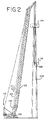
本発明は、多くの種類のクレーンへの適用の可能性を有するが、付属の図に種々のブーム構成で示されている、移動式リフトクレーンに関連して説明するものとする。図示される4つの異なる構成のクレーンがあり、それらは、図1におけるクレーン10、図2−5におけるクレーン110、図6−7に見られるクレーン210の各部分、及び図8−9に見られるクレーン310の各部分である。また、本発明のいくつかの方法は、それらが連続的な掛け回しで装備される限り、従来技術のクレーンを使用して実施され得ることを留意されたい。そのことは、本発明の利点の一つであり、それは、多くの既存のクレーンに大幅な修正することなしに実施され得る。もちろん、本発明の方法は、以下で考察される追加の特徴を、修正し含むクレ-ンで、より容易に実行され得る。
Although the present invention has applicability to many types of cranes, it will be described in connection with a mobile lift crane, shown in various boom configurations in the accompanying figures. There are four different configurations of cranes shown, such as crane 10 in FIG. 1,
クレーン10は図1で操作形態として示される。従来型の移動式リフトクレーンと同様に、クレーン10は、下部体とも称される下部構造体を含み、該構造体はカーボディ12およびクローラ14の形態の可動地面係合部材を含む。2つのクローラ14があり、図1の側面図では、そのうちの1つだけ見ることができる。クレーン10において、地面係合部材は、各側にフロントクローラ及びリアクローラの、二組のクローラを備えることもできる。もちろん、図示されるもの以外の追加のクローラを使用することができ、さらには、タイヤなどの別の種類の地面係合部材を使用することもできる。
The crane 10 is shown in FIG. Similar to conventional mobile lift cranes, the crane 10 includes a lower structure, also referred to as a lower body, which includes a movable ground engaging member in the form of a
回転台20は、上部体とも称されるクレーン10の上部構造体の一部分であり、回転台が、地面係合部材に対して旋回できるように、回転自在にカーボディ12に連結される。クレーン10において、回転台は、旋回リングを有するカーボディ12に装着され、該リングはリングギアを含んでおり、その結果、回転台20は地面係合部材14に対して軸線を中心に旋回することができる。回転台は、その前方部に枢動自在に装着されたブーム22と、ライブマスト28であってその第1の端部で装着されたライブマスト28と、該マストと回転台の後方部との間に接続されたブーム巻上げ索具と、カウンターウェイトユニット34とを支持している。カウンターウェイトは、個々のカウンターウェイト部材が支持部材上に複数積み重ねられた形態であってもよい。
The turntable 20 is a part of the upper structure of the crane 10, which is also referred to as an upper body, and is rotatably connected to the
ブーム巻上げ索具は、ワイヤーロープ25の形態のブーム巻上げラインを備え、該ラインはブーム巻き上げドラム30に巻回され、下部イコライザ37及び上部イコライザ38の滑車に掛け回される。ブーム巻上げドラムは、回転台に接続されたフレームに装着される。索具はまた、ブーム上端と上部イコライザ38との間に接続された固定長ペンダント21も備え、ライブマスト28の上端に装着される。下部イコライザ37は回転台20に直接接続される。この構成により、ブーム巻上げドラム30を回転させると下部イコライザ37と上部イコライザ38との間のブーム巻上げライン25の長さが変化し、それにより回転台20とライブマスト28との間の角度を変え、次に回転台20とブーム22との間の角度を変えることが可能となる。ライブマスト28を使用するのではなく、クレーンには固定マスト又はデリックマストを、固定マスト又はデリックマスト及びブームとの間の角度を変えられるようにイコライザを再配置する状態で、装備することもできる。或いは、ブーム角度をブーム巻上げ機構用の油圧シリンダを使用して制御することもできる。
The boom hoisting rig has a boom hoisting line in the form of a
荷重巻上げライン24は、回転台に接続された第1の荷重巻上げ主ドラム40に巻回される。荷重巻上げライン24の第2の端部は第2の主荷重巻上げドラムに巻回され、該ドラムはブームに装着され、それにより回転台に間接的に装着される。荷重巻上げライン24はブーム上のロープガイド27を通過し、且つブームのトップ及びフックブロック26の滑車に掛け回される。回転台20は、移動式リフトクレーンに一般的に存在する運転室などの他の要素を備える。必要であれば、図1に示されるように、ブーム22は伸張した上部ブームポイント29を含んでもよい。或いは、起伏ジブが主ブームの上端に枢動自在に装着されることもできるし、別のブーム構成が使用されてもよい。伸張した上部ブームポイント29が使用されるとき、荷重巻上げライン24がブームの上端において掛け回される滑車が、実際は、伸張した上部ブームポイント上に配置される。荷重巻上げライン24は連続して掛け回されるので、2つの滑車の組44、46がブームの上端にあり、該滑車の組を通して荷重巻上げラインがフックブロック26の滑車と共に掛け回される。しかしながら、シーブの組44、46の一方は1つのシーブを有するだけでもよく、該シーブは、荷重巻上げラインがフックブロックに移動する前にブームトップにおいて通過するプーリーの役を果たす。
The load hoist
クレーン10は、本発明の好ましい方法に有用である2つの主要な機能を有する。すなわち、1)荷重巻上げラインの張力と関連する状態を検知するクレーンのセンサー、及び、2)クレーンのコンピュータプロセッサーであって、該センサーと接続され、コンピュータプログラム又は作動可能な他のコンピュータ実行可能コードを実行し、荷重巻上げラインの張力に関連する状態を示す信号をセンサーから受け取り、且つドラム40、42の一方に加えた巻回力を制御し、その間、荷重巻上げラインを他のドラムから巻き取るためのコンピュータプロセッサー、である。本明細書では、語句「と連結された」は直接的に連結される又は1つ以上の中間構成要素を介して間接的に連結されることを意味する。そのような中間構成要素には、機械的なコンピュータハードウェア及びコンピュータソフトウェアベースの構成要素が挙げられ得る。センサーは、移動式クローラクレーンに月並みに見られないが、それ自体必ずしも独自である必要はない。
荷重巻上げライン張力センサーは公知であり、この点に関して、公知のタイプのセンサーが使用されてよい。クレーン10では、1つの実施形態によると、センサーは荷重巻上げラインが通過するブームトップに装着された荷重検知シーブ48を含む。センサーは、荷重巻上げラインによって荷重検知シーブに加えられた圧縮力を検知することによって、荷重巻上げラインの張力を測定する。この点に関して、荷重巻上げラインは、第1ドラムから、荷重シーブを越えて、第2ドラムの周囲に送られ、荷重シーブはリードラインの引張り力に関するデータを提供する。
The crane 10 has two main functions that are useful in the preferred method of the present invention. 1) a crane sensor that senses a condition associated with the tension of the load hoist line; and 2) a computer processor of the crane, connected to the sensor, computer program or other computer executable code operable. In order to receive a signal from the sensor indicating a condition related to the tension of the load hoist line and to control the winding force applied to one of the
Load hoist line tension sensors are known, and in this regard, known types of sensors may be used. In the crane 10, according to one embodiment, the sensor includes a
クレーンのコンピュータプロセッサーであって、該クレーンの少なくともいくつかの操作を制御するコンピュータプロセッサーもまた公知である。このようなコンピュータプロセッサーは、コンピュータ使用可能媒体と接続されてもよく、該媒体は、そこに含まれたコンピュータ読み込み可能プログラムコードを有する。荷重巻上げライン張力センサーなどのセンサーに接続されたコンピュータプロセッサーもまた公知である。この点に関してもまた、本発明は公知のクレーンの構成要素を使用してもよい。しかし、好ましい実施形態においては、プログラムコードは、コンピュータプロセッサーによって実行され、荷重巻上げライン張力に関する状態を示す信号をセンサーから受け取り、その後、ドラム40、42の一方に加えられた巻回力を制御し、その間、荷重巻上げラインが、その張力に基づき他方のドラムから巻き取られる。
Computer processors for cranes that control at least some operations of the crane are also known. Such a computer processor may be connected to computer usable media, which has computer readable program code contained therein. Computer processors connected to sensors such as load hoist line tension sensors are also known. Also in this regard, the present invention may use known crane components. However, in a preferred embodiment, the program code is executed by a computer processor to receive a signal from the sensor indicating a condition related to load hoist line tension and then control the winding force applied to one of the
クレーン10に見られる幾つかの別の構成要素があり、それらは本発明の好ましい実施形態に対して特に有用である。好ましくは、ドラム40及び42は、ベイルリミットセンサーを各々備えている。図10と図11は、例示的なベイルリミットセンサーアセンブリ50を示し、該アセンブリはクレーン10,110のいずれに使用されてもよく、図は特にクレーン10のドラム40に関連して示されている。ベイルリミットセンサーアセンブリ50は、その設計において従来型であり得る。ベイルリミットセンサーアセンブリ50はベースプレート52と、ベースプレート52に枢動可能に装着されたアーム54と、アーム54の端部に回転可能に装着されたローラー56とを含む。ベースプレート52は、ベイルリミットセンサーをドラム40に近接してクレーンに装着する。ベースプレート52とアーム54の間に装着されたスプリング58は、図11に示すように、ドラムのワイヤーロープ又はドラム自体に接触して、ローラー56を保持する。ワイヤーロープ24は、ドラムに巻回されると、ドラム40のラギング溝43に収まり、ローラー56をドラムから離れる方向に押すことになる。ワイヤーロープ24の層毎に、ローラー56及びアーム54をドラム40からますます離れる方向に押すことになる。当然ながら、ワイヤーロープ24がドラム40から取り除かれると、ローラー56及びアーム54はドラム40にますます近づき得る。センサー60は、ベースプレート52とアーム54上の伸張部57の間に連結されて、ローラー56の下部の、ワイヤーロープの最後の層がドラム40から無くなると検知する。センサー60はこの状態を検出するリミットスイッチを含む。ベイルリミットセンサーアセンブリ50は、ドラム40の側部から内向きに3本のロープ直径周囲に配置されることにより、ロープ24の最後の層がドラム40から無くなり、且つローラー56がドラム40の表面に接触するとき、ドラムには少なくとも3巻き、好ましくは4巻きのロープ24がいまだ有ることになる。センサー60は、従来の方法でインターフェース(図示せず)に接続されることにより、ローラー56の位置は、コンピュータ用の入力として使用することができ、該コンピュータはクレーンの他の機能を制御するのを補助するベイルリミットセンサーの位置を使用する。センサー60は、代わりに、ベースプレートに対するアームの複数の相対位置を検出するように設計されることもでき、当然、該相対位置はドラム40のワイヤーロープ24の層数に直接関連付けられ、この情報はコンピュータに提供される。
There are several other components found in the crane 10, which are particularly useful for the preferred embodiment of the present invention. Preferably, drums 40 and 42 are each equipped with a bail limit sensor. FIGS. 10 and 11 show an exemplary bail
本発明は、ドラム40及び42それぞれが荷重巻上げラインの長さに直径に対比したある直径と長さを有するとき、最も有用であり、それは、フックブロックがブームトップに出来る限り近接しているとき、ワイヤーロープが一方のドラムに少なくとも3層の深さであるようになっている。追加の層、例えば1つのドラムに6又は7層により、本発明の利点は増す。
The present invention is most useful when each of the
荷重巻上げライン24は、好ましくは均一の直径を有するワイヤーロープより成り、該均一の直径は該ロープのドラム40に連結された第1端部からドラム42に連結された第2端部までその長さ全体に亘っている。荷重巻上げライン24は、型圧縮された外側ストランド(die−compacted outer strands)を有するワイヤーロープから成ってもよい。ワイヤーロープは、典型的には約16mmと約50mmの間の直径を有する。
The
巻回力は、好ましくは油圧油の加圧源により生成され、コンピュータ読み込み可能プログラムコードは、好ましくは油圧モータに加えられた油圧油の圧力を制御するために実行されるようになされている。機上のコンピュータ内に埋め込まれたクレーン制御は、オペレータの制御操作入力に基づいた巻上げ機能を制御するのに利用されてもよい。コンピュータは、一般に移動式リフトクレーンに使用されている電気油圧制御を使用して油圧装置を制御してもよく、その結果、例えば、該コンピュータはソレノイドの作動の信号を送り、該ソレノイドはパイロットバルブを開閉し、次に該バルブは別の油圧バルブを開閉することになる。即ち、該コンピュータは油圧ポンプ制御又は電気変位制御の一回の動作を制御して圧力を制御してもよい。好ましくは、引張工程の間ラインを巻き取っているドラムの引止め力もまた、油圧油の加圧源に接続された油圧式モータによって発生させられ、コンピュータ読み込み可能プログラムコードもまた、好ましくは、引止め力を生じさせる油圧モータに加えられた油圧油の圧力を制御するために実行されるようになされている。油圧モータの代わりに、電気モータもまたドラム上の力を提供するために使用されることもできる。コンピュータはこうしたモータを操作する電気信号の制御に使用されることも容易にできる。或いは、第2ドラムの引止め力は、機械的ブレーキにより提供される。 The winding force is preferably generated by a hydraulic oil pressure source, and the computer readable program code is preferably executed to control the pressure of the hydraulic oil applied to the hydraulic motor. The crane control embedded in the on-board computer may be used to control the hoisting function based on the operator's control operation input. The computer may control the hydraulic system using the electrohydraulic control commonly used in mobile lift cranes, so that, for example, the computer sends a signal to actuate a solenoid, which solenoid pilot valve Then the valve will open and close another hydraulic valve. That is, the computer may control pressure by controlling one operation of hydraulic pump control or electric displacement control. Preferably, the retaining force of the drum winding the line during the tensioning process is also generated by a hydraulic motor connected to a hydraulic oil pressure source, and the computer readable program code is also preferably pulled. Executed to control the pressure of the hydraulic fluid applied to the hydraulic motor that generates the stopping force. Instead of a hydraulic motor, an electric motor can also be used to provide the force on the drum. Computers can also be easily used to control electrical signals that operate such motors. Alternatively, the retaining force of the second drum is provided by a mechanical brake.
ワイヤーロープの製造業者はワイヤーロープ破断力の2%から5%の力でドラムにロープを巻き取ることを推奨している。しかしながら時には、巻き取りは破断力の1%の力でなされてもよい。定格ライン引張り力とロープ破断力の間の5から1の設計安全係数を使用するとき、これは、巻き取り力が定格ライン引張り力の5%から25%であるべきことを意味することになる。定格ライン引張り力は、クレーンが所定の作業のために設置されるときの公知のパラメータであるので、第1ドラムに加えられた巻回力は制御され、巻回力が加えられる前に決められた所定の張力範囲内で荷重巻上げラインを第2ドラムから第1ドラム上に巻き取るのが好ましい。好ましくは、所定の張力範囲は、荷重巻上げラインの定格ライン引張り力の約5%と約25%の範囲で抑えられる。 Wire rope manufacturers recommend winding the rope around the drum with a force of 2% to 5% of the wire rope breaking force. However, sometimes winding may be done with a force of 1% of the breaking force. When using a design safety factor of 5 to 1 between the rated line tensile force and the rope breaking force, this means that the winding force should be 5% to 25% of the rated line tensile force. . Since the rated line pulling force is a known parameter when the crane is installed for a predetermined operation, the winding force applied to the first drum is controlled, and is set to a predetermined value determined before the winding force is applied. It is preferable to wind the load hoisting line from the second drum onto the first drum within the tension range. Preferably, the predetermined tension range is constrained between about 5% and about 25% of the rated line tensile force of the load hoist line.
本発明の方法を、クレーン110の第2の実施形態を示す図2から図5に関連付けて説明してゆく。クレーン110は、ブーム122がより長いことを除きクレーン10と同じ物である。風力タービンを支持するのに使用されているタワー102の隣に設置されたクレーン110を示す。描かれた方法では、荷重巻上げライン124は、風力発電ナセル104を降ろすのに使用されることになる(タービンブレードは既に取り外されており、図示されていない)。より詳細に説明されるとおり、該方法の基本的なステップは、a)第2ドラムに引止め力を加えるステップと、b)第2ドラムの引止め力よりも大きい巻回力を第1ドラムに加えるステップと、c)フックブロックの移動を制限しながら、巻回力と引止め力を加えるステップであって、それにより、荷重巻上げラインを、第2ドラムからブームトップとフックブロックのシーブを通り第1ドラムまで荷重巻上げラインの張力を維持しながら巻き取り、その結果荷重巻上げラインが、あらかじめ第2ドラムに巻回されていたものよりも大きい張力で第1ドラムに巻回される。図示した方法の実施形態において、第1ドラムはブームに装着されたドラム142であり、第2ドラムは回転台に装着されたドラム140である。当然、両ドラムを逆に使用することもでき、第1ドラムはドラム140となり、第2ドラムはドラム142となる。
The method of the present invention will be described in connection with FIGS. 2 to 5 which shows a second embodiment of the
好ましい手順は、上記に列挙したものに加えて追加のステップを含む。図2に示す好ましい手順の第1のステップは、フックブロック126と索具をドラム140を使用して所望の高さまで吊上げることである。この場合、フックブロックを実質的に荷重の無い状態で荷重巻上げラインを第2ドラムに巻回することにより、対象物に取り付けることができる高さまでフックブロックを吊上げる。矢印111は荷重巻上げライン124がドラム140によって巻き取られているのを示し、フックブロックが吊上げられているのを矢印112によって示す。この第1ステップの間、ドラム142は止まったままであるのが好ましい。フックブロック126の吊上げから生じるリードラインの引張り力は、定格ライン引張り力の5%未満が好ましく、定格ライン引張り力の3%前後がより好ましい。
The preferred procedure includes additional steps in addition to those listed above. The first step of the preferred procedure shown in FIG. 2 is to lift the
次に、図3に示すように、フックブロック126を、持ち上げる対象物、この場合ナセル104に索具131によって取り付ける。ドラム140は、索具131がぴったり合うまで荷重巻上げラインを引き続ける。次に、ドラム140を繰り出し引止めとして使用して、ロープ124をドラム142に巻き取る。ドラム140は引止め力を維持するので、ドラム142でのリードライン引張り力は定格ライン引張り力の5%と25%の間にあり、その間、フックブロックの移動は制限される。フックブロックは対象物に取り付けられて所定位置に保持され、該対象物、この場合持ち上げられるナセル104は最終的には吊上げられるであろう。この操作中、2つのドラム140と142からの合計の力はナセル104を持上げるには不十分であることを理解されるであろう。矢印113は荷重巻上げライン124がドラム140に引き込まれるのを示し、一方矢印114は荷重巻上げラインがドラム140から引き出されるのを示す。
Next, as shown in FIG. 3, the
次に、図4に示すように、ロープをドラム142に堅く巻き取る状態で、持上げたナセル104を支柱102から持上げることができる。矢印116はフックブロックが吊上げられるのを示す。このことは、図示した方法において、矢印115によって示すように、ドラム142に荷重巻上げラインを巻回することにより行われる。このようにして、荷重巻上げラインを第1ドラムに巻回することにより、対象物を持上げる。或いは、このステップにおいて対象物を持上げるために、第2ドラム又は同時に両方のドラムを使用することもできる。
Next, as shown in FIG. 4, the raised
最後に、図5に示すように、ナセル104を地面に降ろすことができる。これは、矢印117に示す、第1ドラム142に巻き付けられる荷重巻上げライン124を巻き戻すことによって行われ、それによって、矢印118に示す、フックブロックと対象物が降ろされる。このステップにおいて、ドラム140は静止状態に保持される。
Finally, as shown in FIG. 5, the
図6と図7は、本発明の方法を実施するのに特に適したクレーン210の上端部分の詳細を示す。図6に、ブーム222の上端にあるブラケットを、明確にするために、取り付けられているシーブ又は上部ブームポイントの無い状態で示す。図7はプーリー246を備える上部ブームポイント223とブラケットに取り付けられたブームトップシーブ244とを示す。
6 and 7 show details of the upper end portion of the
図6のブームトップ上のブラケットは、起伏ジブ(図示せず)又はブームの上端に伸張する上部ブームポイントを連結するために使用される2組の雌型ブラケット232と、伸張する上部ブームポイントが使用されないときは、下部ブームポイントのシーブ244を保持するフレームを装着しているブラケット234とを含む。ブラケット236は複数のラグを支持し、該ラグのそれぞれは上部ブームポイントを連結してもよい穴238を含む。図6はまた、ワイヤーロープガイド227、229及びブームの上端222に装着されている荷重検知シーブ248を示す。これらは、その作業位置で示されているが、ピン連結で連結されているので、それらを、ブームトップが作業現場間で運搬されるときに、収容できる位置へと前方に折り畳むことができる。
The bracket on the boom top of FIG. 6 includes two sets of
図7は、荷重巻上げライン224の連続的な掛け回し及び荷重検知シーブ248を使用する方法を示す。ライン224は回転台(図示せず)上の第1ドラムから第1ワイヤーロープガイド227まで進み、それから上部ブームポイント223のプーリー246を通過する。そこから、荷重巻上げライン224を、フックブロック226内のシーブまで通し、下部ブームポイント内のシーブ244でラインの多くの部分を使用して掛け回す。ラインの最後の部分を、シーブ224から荷重検知シーブ248及びワイヤーロープガイド229を越えて通し、その後ブーム(図示せず)に装着されたドラムまで下方に進める。荷重巻上げライン224の張力は、それに正比例する力でシーブ248を下方に押すであろうことが分かり得る。荷重検知シーブに組み込まれたセンサーは従来の方法(図示せず)で支援し、信号をコンピュータへの入力(直接に又はインターフェースを介してのどちらか)として提供する。
FIG. 7 illustrates a method of using continuous winding of load hoist
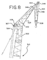
図8と図9はクレーン310の上端部分を示し、図は伸張する上部ブームポイント323がブラケット332に取り付けられている以外クレーン210と同様である。ワイヤーロープガイド327と329はなおブーム322の上端のブラケットに取り付けられている一方、荷重検知シーブ348は伸張する上部ブームポイントに取り付けられている。伸張した上部ブームポイントはシーブ344と346を含み、それを通過して荷重巻上げラインはフックブロック326内のシーブで連続的に掛け回される。
FIGS. 8 and 9 show the upper end portion of the
高い高さから地面への対象物の移動に加えて、本方法は、ドラムにロープを堅く巻き取るために使用され、対象物をクレーンの高さから地下道の立抗へなど、より低い高さに降下させることができる。本発明は地面を動き回る移動式クローラクレーン以外の用途、例えば深海の石油掘削装置上のプラットホームクレーンなど、を有するので、対象物を持ち上げつつある高さと、対象物を降ろしつつある高さであって、地面の高さを参照するのではなく、i)カーボディ12などのクレーンの地面係合部材を備える下部機構と、ii)上部機構であって、回転台20など下部機構に対して旋回できるように下部機構に回転可能に接続された上部機構との間の、連結部の平面の高さを参照した高さの比較が参考になる。ナセル104を移動するような吊り上げに関しては、この平面は基本的に地面の高さにある。このようにして、いくつかの操作では、図2から図5に図示されるように、持上げの初めに対象物はクレーン上部機構とクレーン下部機構間の連結部上方の高さにあり、それから、上部機構と下部機構間の連結部に近接した高さまで降ろされる。一方、他の時点で、対象物は上部機構と下部機構間の連結部の下方の高さまで降ろされる。
In addition to moving the object from high height to the ground, this method is used to tightly wind the rope around the drum, lowering the object to a lower height, such as from the height of the crane to the resistance of an underpass. Can be lowered. Since the present invention has applications other than a mobile crawler crane that moves around the ground, such as a platform crane on a deep-sea oil drilling rig, the height at which the object is being lifted and the height at which the object is being lowered Rather than referencing the height of the ground, i) a lower mechanism including a ground engaging member of a crane such as the
本発明の好ましい工程の基本的なステップの一つは、巻回力及び引止め力を加える一方、フックブロックの移動を制限し、1つのドラムから他のドラムにワイヤーロープを移すことである。もし、このステップにおいて、引止め力が第2ドラムに加えられた状態で、フックブロックの移動が制限されなければ、ワイヤーロープが第1ドラムに巻回されたとき、ワイヤーロープが第2ドラムから離れ落ちるよりむしろ、フックブロックがブームトップにより近くに引き寄せられるであろう。フックブロックは、本ステップにおいて、完全に静止している必要はないが、その動きは制限されなければならないことを留意されたい。持上げられる対象物にフックブロックを取付けることに加えて、フックブロックの移動を制限するために意図された、いくつかの他の方法がある。初めに、フックブロックは、その移動を制限するために、持上げられるべき対象物とは異なる対象物に取付けられてもよい。例えば、一塊のクレーンカウンターウェイトが使用されてもよい。この第1の代替方法を使用して、引張操作(それは、所望のライン引張張力が、荷重巻上げラインに引張りステップのためにかけられると生成される持上げ力より対象物が重いとき、生じる)の間、対象物は地面(又は他の何らかの支持物)に留まっていてもよいし、或いは、第2ドラムから第1ドラムへ所定の張力で、荷重巻上げラインを巻き取る操作の間対象物が持上げられて、ほぼ一定の高さに吊るされていてもよい。対象物が持上げられる場合、荷重巻上げラインが第1ドラムに巻回される張力は、対象物の重量に基づくことになり、引止め力と巻回力は、対象物があまりにも高く吊上げられないように確実に制御されなければならない。こうした第1の代替方法は、荷重巻上げラインが第1ドラムへの所定の張力で巻き取られた後、地下道の立杭に対象物を降下させるために使用される操作に、特に有用であり得る。こうした操作において、ブームはかなり短くてもよく、フックブロックを引張操作の間、空中に極めて高く上昇させる必要はない。 One of the basic steps of the preferred process of the present invention is to apply the winding and retaining forces while limiting the movement of the hook block and transferring the wire rope from one drum to the other. In this step, if the movement of the hook block is not restricted in the state where the holding force is applied to the second drum, the wire rope is removed from the second drum when the wire rope is wound around the first drum. Rather than falling off, the hook block will be drawn closer to the boom top. Note that the hook block need not be completely stationary in this step, but its movement must be limited. In addition to attaching the hook block to the object to be lifted, there are several other methods that are intended to limit the movement of the hook block. Initially, the hook block may be attached to a different object than the object to be lifted to limit its movement. For example, a lump of crane counterweight may be used. Using this first alternative method, during the tensioning operation (which occurs when the object is heavier than the lifting force generated when the desired line tension tension is applied to the load hoist line for the tensioning step) The object may remain on the ground (or some other support), or the object may be lifted during the operation of winding the load hoist line from the second drum to the first drum with a predetermined tension. And may be suspended at a substantially constant height. When the object is lifted, the tension at which the load hoisting line is wound around the first drum will be based on the weight of the object, so that the holding force and the winding force will not lift the object too high. Must be reliably controlled. Such a first alternative method may be particularly useful for operations used to lower an object to an underpass stake after the load hoist line has been wound with a predetermined tension to the first drum. . In such operations, the boom may be quite short and the hook block need not be raised very high into the air during the pulling operation.
フックブロックの移動を制限する第2の方法は、クレーンで持上げることができ、荷重巻上げラインに引張操作のために望まれるよりも高い張力を、必要とするであろう対象物とは違って、事実上静止している対象物にクレーンによってフックブロックを取付けることである。それによって、フックブロックは、クレーンが持上げるには重すぎる対象物に、又はクレーンが、地面から引き離すことができない方法で地面に固定されている部材に、取付けられてもよい。クレーン転倒支点からの荷重の範囲は、この方法で考慮され、対象物の重量により生じた荷重モーメント、又は地面から対象物を引き離すことを必要とされるであろう力が大変大きいので、クレーンは、対象物が持上げられるか引き離される前に、転倒することになるであろう。 A second way to limit the movement of the hook block is that it can be lifted by a crane, unlike objects that would require higher tension in the load hoisting line than desired for the pulling operation. It is to attach a hook block by a crane to a substantially stationary object. Thereby, the hook block may be attached to an object that is too heavy for the crane to lift or to a member that is fixed to the ground in such a way that the crane cannot be pulled away from the ground. The range of loads from the crane overturning fulcrum is taken into account in this way, and because the load moment caused by the weight of the object or the force that would be required to pull the object away from the ground is very large, , Before the object is lifted or pulled away, it will fall.
フックブロックの移動が制限される第3の代替方法は、フックブロックを、ブームトップが干渉してフックブロックがさらに吊上げられるのを防ぐ位置まで、吊り上げることである。この方法は、フックブロックとブームトップ間に間隙体(スペーサ)が配置されるときに、フックブロックが干渉する位置まで吊り上げられてもよく、荷重巻上げラインは第2ドラムから第1ドラムに巻き取られる一方、該間隙体はフックブロックとブームップの構成要素を互いに損傷しないように構成される。図8と図9はこの機構を示す。クレーン310は間隙体としての役目を果たすフレーム342が収容されている。本発明の方法を実施するのに、フックブロック326は、図9に示すように、フレーム342に接触するまで吊上げられる。フックブロックは、引止め力が加えられている状態で、荷重巻上げラインが一方のドラムから他方のドラムまで巻き取られる間、この位置に維持される。フレーム342は十分頑丈に構築されているので、ライン324の複数部分の引止め力及び巻回張力により生成された力がフレームを圧壊することはない。フレームはクレーン操作全体を通して、ブームトップに取付けられたままでよい。代わりに、フレームはフックブロックの上端に取り付けることもでき、その場合、該フレームは、フックブロックが地面に近づいた状態で取付けることもできる。その場合、該フレームは引張操作の間取り付けられたままとなるであろうが、その間、荷重は高い高さから地面に降ろされ、別の引張操作が直ちに続こうとしなかった場合、対象物がフックから取り外された後、該フレームが取り除かれることも可能である。
A third alternative method in which the movement of the hook block is restricted is to lift the hook block to a position that prevents the boom top from interfering with the boom block from further lifting. In this method, when a gap (spacer) is disposed between the hook block and the boom top, the hook block may be lifted to a position where the hook block interferes, and the load hoisting line is wound from the second drum to the first drum. On the other hand, the gap is configured so as not to damage the hook block and boom-up components. 8 and 9 show this mechanism. The
フックブロックの移動を制限する第4の代替方法は、フックブロックをクレーンの別の部分に取付けることである。例えば、各クローラーフレーム間の梁は、フックブロックが、張力操作の間、その移動を制限するために取付けられる、結合点を装備されることもできる。 A fourth alternative to limit the movement of the hook block is to attach the hook block to another part of the crane. For example, the beam between each crawler frame can be equipped with a connection point where the hook block is attached to limit its movement during tensioning operations.
荷重巻上げラインの張力に関することを検知できるクレーン内の幾つかの状態がある。例えば、モータにトルクを与え第1ドラムを回転させる油圧油の流体圧力が、(ロープの層がドラム上にあるという印とともに)検知されて、リードラインの引張り力に関する情報の提供に使用されてもよい。ブームがブーム懸架部で支持されているときは、クレーンは、ブーム懸架部の張力を測定するために、ブーム懸架部の荷重ピンを提供され、測定された張力は、(ブーム角度、及びフックブロック索具中のラインの多くの部分の情報とともに、)リードラインの引張に関する情報の提供に使用される。もし、フックブロックの移動がフックブロックを対象物に取付けることにより制限され、また、クレーンがフックブロック中に荷重センサーを提供されるなら、その荷重ピンセンサーは、リードラインの引張り力に関する情報を提供するために使用されてもよい。或いは、荷重センサーが、フックブロックを対象物に取り付けている索具中に設けられ、リードラインの引張り力に関する情報を提供するために使用されてもよい。荷重センサーは、荷重リンクの形態、必要に応じて、荷重ピン又は幾つかの他の荷重セルの形態であってもよい。 There are several conditions in the crane that can detect things related to the load hoist line tension. For example, the fluid pressure of the hydraulic oil that torques the motor and rotates the first drum is sensed (along with an indication that the rope layer is on the drum) and is used to provide information on the pulling force of the lead line. Also good. When the boom is supported by the boom suspension, the crane is provided with a boom suspension load pin to measure the boom suspension tension, and the measured tension (boom angle, and hook block) Used to provide information on leadline tension (along with information on many parts of the line in the rigging). If the movement of the hook block is limited by attaching the hook block to the object and the crane is provided with a load sensor in the hook block, the load pin sensor provides information on the leadline pull force May be used to Alternatively, a load sensor may be provided in the rigging that attaches the hook block to the object and may be used to provide information regarding the leadline pulling force. The load sensor may be in the form of a load link, optionally a load pin or some other load cell.
先に述べたように、荷重巻上げライン中のリードラインの引張り力が計算され得る情報が、巻き取り操作の間収集されるのが好ましく、該情報は、巻き取り操作の間定格ライン引張り力の約5%と25%の間の範囲に、ライン引張り力を維持するために使用される。 As mentioned earlier, information that can be used to calculate the lead line pull force in the load hoist line is preferably collected during the winding operation, and this information can be used for the rated line pull force during the winding operation. Used to maintain line tension in the range between about 5% and 25%.
本発明のクレーンオペレータによって使用される好ましいステップは、下記のごとくである。オペレータは、ドラムの一つを制御し、フックブロックを停止位置まで引張る。前述したように、停止位置は、該ブロックを、吊り上げ対象物、又は他の対象物若しくはクレーン自体に取付ける位置であってもよく、又は該ブロックをブームトップに取付けられた間隙体まで持ってきた位置であってもよい。次に、オペレータは図12に関連して以下に述べる制御プログラム内のロープ引張モードを選択する。次に、コンピュータ制御は、ドラム2を働かせ、ドラム1からドラム2にロープを引張ることになる。制御プログラムの指示で、ドラム1はロープを「引き止め」し、ロープが、ドラム2に巻き取られると、所望の張力を提供するであろう。オペレータが、荷重巻上げラインの十分な長さが移動したと判断したとき、又はベイルリミットセンサーが、ラインの最大量がドラム1から巻き取られたことを知らせたとき、オペレータは、通常の巻上げモード操作を選択し、対象物を取付けてドラム2から降ろすために普通に操作する。その所定の手順は、ベイルリミットに至る前に終えることができる。いったん、ドラム1のロープが第1層まで下がると、必要なら、所定の張力でロープを巻回しながらドラムに巻き戻すことは、望ましい状況であろう。ドラムが終端まで巻き取られないことを確実にするために、第一にベイルリミットがある。 The preferred steps used by the crane operator of the present invention are as follows. The operator controls one of the drums and pulls the hook block to the stop position. As described above, the stop position may be a position where the block is attached to a lifting object or other object or the crane itself, or the block has been brought to a gap body attached to the boom top. It may be a position. Next, the operator selects a rope pulling mode in the control program described below in connection with FIG. The computer control then activates drum 2 and pulls the rope from drum 1 to drum 2. At the direction of the control program, the drum 1 will “clamp” the rope, and when the rope is wound onto the drum 2, it will provide the desired tension. When the operator determines that a sufficient length of the load hoisting line has moved, or when the bail limit sensor informs that the maximum amount of line has been taken up from the drum 1, the operator is in normal hoisting mode. Select the operation and operate normally to attach and remove the object from the drum 2. The predetermined procedure can be completed before reaching the bail limit. Once the drum 1 rope has been lowered to the first layer, it may be desirable to wind it back onto the drum while winding the rope with a predetermined tension, if necessary. In order to ensure that the drum does not wind up to the end, there is first a bail limit.
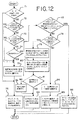
図12は第1のコンピュータプログラムサブルーチンのフローチャートを示し、クレーンオペレータが本発明の方法を実施できるようにするために使用されてもよい。サブルーチンが開始すると、プログラムは初めにブロック71で、ロープ引張モードが有効であるかどうか問い合わせる。有効でないなら、クレーンは、標準ロジックで、ポンプと、モータと、ドラム40のブレーキとを制御する操作を続け(ブロック76)、サブルーチンを終了する。サブルーチンは頻繁に繰り返される(例えば、30ミリセカンド毎)ので、ロープ引張モードがオペレータによって有効にされるとすぐに、ブロック71の条件は満たされ、ブロック72でプログラムは、どちらか一方のドラム停止スイッチが開であるかどうかを問い合わせるが、このスイッチが開であることは、オペレータが操作卓のスイッチを、ドラムが使用されるべきであるかどうかを表示するために使用したことを意味する。もし、スイッチが開なら、それは、開回路があることを意味し、ドラムが使用されようとしていなく、「止められた状態」であることを示す。もし、どちらの停止スイッチも開でないなら、ブロック73で、プログラムは、一方のドラムだけが操作命令を有しているかどうかを問い合わせるが、それは、該スイッチがその中立の位置から動かされていることを意味し、オペレータがドラムを回転させようとしていることを示す。もしそうであるなら、ブロック74でプログラムは操作命令がゼロ未満であるかどうかを問い合わせるが、該ゼロ未満は、信号が巻下げ操作を命令していることを意味し、その操作ではワイヤーロープがドラムから巻き解かれる。もし操作命令がゼロ未満であるか、又はブロック73の条件が満たされないなら、又はブロック72で、どちらのドラム停止スイッチも開でないなら、プログラムは実際のライン張力を読み取り、現在の張力が定格ライン引張り力目標の5%から25%を満たすかどうかを判定するために使用される。この実際の張力は、ブロック75で、ブロック81で使用されるメモリに書き込まれ、クレーンはブロック76で標準ロジックを使用し続け、サブルーチンが終了する。
FIG. 12 shows a flowchart of a first computer program subroutine that may be used to enable a crane operator to perform the method of the present invention. When the subroutine starts, the program first queries at
もし、一方のドラムだけが操作命令を有し、該操作命令がブロック74でゼロ未満でない(その制御はワイヤーロープをドラムに巻き取る操作を示している)なら、プログラムはブロック77で、どちらかのドラムが、非2ブロック(anti−two block)(ATB)、ベイルリミット、又は荷重モーメントなどの操作限界に達しているかどうかを問い合わせる。もし達していれば、警報がオペレータに送られて、ポンプと、モータと、ブレーキとが、ブロック86で安全な状態に設定され(ポンプはゼロ出力になり、モータは最大押しのけ容積に設定され、ブレーキは作動状態に設定され)、サブルーチンは終了する。しかしながら、もし操作限界がブロック77で事実上達していないなら、サブルーチンは、ブロック78で両方のドラムのブレーキが離されているかどうかを問い合わせる。もし、離されていなければ、モータはブロック84で最大押しのけ容積に調整され(ストローク調整され)、圧力メモリ基準が満たされるまで、圧力フィードバックがブロック85でポンプ制御に使用されて、サブルーチンが終了する。当然、サブルーチンは、再びすぐに走ることになり、このとき、圧力メモリ基準が満たされると、ブレーキは離された状態にあるであろう。
If only one drum has an operation command and the operation command is not less than zero at block 74 (the control indicates an operation to wind the wire rope around the drum), the program is at
もし、両方のドラムのブレーキがブロック78で離された状態にあるなら、サブルーチンはロープ引張操作に進むであろう。ブロック79で、操作命令を有するドラムは、巻き取られるべきドラムとして設定され、もう一方のドラムは引止めドラムとして設定される。ブロック80で、圧力フィードバックは、各モータを目標モータ位置(最小押しのけ容積)まで駆動するために使用され、それは速度を最大にし、且つ最大の制御性を一定のモータ変位を維持することにより提供する。ブロック81で、サブルーチンは、ブロック75で書き込まれた張力を読み取り、それが目標限度(定格ライン引張り力の5%から25%)内にあるかどうかを評価する。もし限度内でなければ、ブロック82で、張力目標が算出されるが、それはライン張力を増加させるか減少させるか、或いは他の方法で操作することを意味し、その結果、該張力目標が限度内に持ってこられる。もし限度内であるなら、又は張力目標が一旦算出されると、ブロック83で、プログラムは、ポンプ命令を所望のライン張力を維持するように制御する。ロープ引張シーケンスは、オペレータが巻上げ制御ハンドルをニュートラルに戻すまで、入力の何かに状態変化があるまで、又はベイルリミットに達するまで、継続するであろう。フローチャートに要点を述べたサブルーチンは、繰り返して呼び出される。従って、もしいずれの判定ブロックの入力に変化があっても、プログラムのフロー及び結果としてもたらされる出力は、サブルーチンの呼び出し毎に変化することができるであろう。巻き取り操作はこのようにして、どの入力(例えば、停止スイッチ、ハンドル、ベイル限度を含む操作限度など)の状態変化によってでも終了することができる。
If both drum brakes are released at
図13は第2のコンピュータプログラムサブルーチンのフローチャートを示し、該サブルーチンは、クレーンオペレータに本発明の方法を実施できるようにするために使用されてもよい。図13のサブルーチンは、図12のサブルーチンに極めて似ている。主な相違は、オペレータのインターフェースに二つの変更を示し、それらは、システムを操作しやすくするように構成された。図12のフローチャートにおいて、一方の荷重ドラムから他方へロープを移動させる間望まれるライン張力は、二つの荷重ドラムのただ一方のみが動作している間、連続的にアップデートされた。図13のフローチャートにおいては、所望のライン張力は、サブルーチンが走るのに先立って、オペレータの入力としてディスプレイのスクリーン(図示せず)を介して処理される。従って、張力をアップデートするいかなる記載も、第2のフローチャートから削除された。第2に、図12のフローチャートは、(ハンドルの値)>0、即ち、意図したドラムが巻き取られ、意図しないドラムが引止めドラムとなるであろうことを示したときだけロープ引張制御は機能している。図13のフローチャートにおいて、ハンドルはどちらの方向にも作動することができ、制御システムは、意図された動きを認識することになり、巻き取りドラムと引止めドラムを適切に割り当てる。 FIG. 13 shows a flowchart of a second computer program subroutine that may be used to allow a crane operator to perform the method of the present invention. The subroutine of FIG. 13 is very similar to the subroutine of FIG. The main difference shows two changes to the operator interface, which were configured to make the system easier to operate. In the flowchart of FIG. 12, the line tension desired while moving the rope from one load drum to the other was continuously updated while only one of the two load drums was operating. In the flowchart of FIG. 13, the desired line tension is processed through a display screen (not shown) as operator input prior to the subroutine running. Therefore, any description to update the tension was deleted from the second flowchart. Second, the flowchart of FIG. 12 shows that (rope value)> 0, that is, the rope tension control is only when the intended drum is wound up and the unintended drum will become the retaining drum. It is functioning. In the flowchart of FIG. 13, the handle can operate in either direction, and the control system will recognize the intended movement and assign the take-up drum and the retaining drum appropriately.
図13のサブルーチンが始まると、プログラムは初めに、ブロック171でロープ引張モードが有効であるかどうか問い合わせる。もし、有効でないなら、クレーンは標準ロジックで操作を続けることで、ポンプと、モータ及びドラム40(ブロック176)のブレーキとを制御して、サブルーチンを終了する。しかしながら、ロープ引張モードがオペレータによって有効にされるとすぐに、ブロック171の条件は満たされて、ブロック172でプログラムは、どちらか一方のドラム停止スイッチが開であるかどうかを問い合わせる。もし、開でなければ、プログラムは、一方のドラムだけがハンドル命令を有するかどうか問い合わせる。もし、ブロック173の条件が満たされないなら、又はどちらのドラム停止スイッチもブロック172で開なら、クレーンは標準ロジックをブロック176で使用し続けて、サブルーチンを終了する。
When the subroutine of FIG. 13 begins, the program first queries at
もし、一方のドラムだけが操作命令を有するなら、プログラムはブロック177で、どちらか一方のドラムが操作限度を有するかどうかを問い合わせる。もし有するなら、警報がオペレータに送られ、ポンプと、モータ及びブレーキは、ブロック186で安全な状態に設定されて、サブルーチンを終了する。しかしながら、もしブロック177で、実際には操作限度がないなら、サブルーチンはブロック178で、両方のドラムのブレーキが離されているかどうかを問い合わせる。もしそうでないなら、モータはブロック184で最大押しのけ容積に調整され(ストローク調整され)、圧力メモリ基準が満たされるまで、圧力フィードバックがブロック185でポンプ制御に使用されて、サブルーチンが終了する。当然、サブルーチンは、再びすぐに走ることになり、このとき、圧力メモリ基準が満たされると、ブレーキは離された状態にあるであろう。
If only one drum has operating instructions, the program queries at
もし、両方のドラムのブレーキがブロック178で離された状態にあるなら、サブルーチンはロープ引張操作に進むであろう。ブロック179で、操作命令が使用され、どのドラムが巻き取られるべきか、及びどのドラムが引き止めドラムであることになるかを決定する。ブロック180で、圧力フィードバックが使用され、各モータを目標モータ位置の状態に駆動する。ブロック183で、プログラムは、ポンプ命令を所望のライン張力を維持するように制御し、該命令はオペレータによって入力された後、ロープ引張シーケンスが始められる。このようにして、コンピュータはポンプを制御し、所望の張力を実現する。図12のサブルーチンのように、ロープ引張シーケンスは、オペレータが巻上げ制御ハンドルをニュートラルに戻すまで、停止スイッチを開くか、ベイル限度に達するかなど入力の何かに状態変化があるまで、継続するであろう。
If both drum brakes are released at
記載された実施形態の幾つかの態様は、ソフトウェアモジュールまたは構成要素として示されている。ここに使用されるとき、ソフトウェアモジュール又は構成要素は、どのような形式のコンピュータ命令又はコンピュータ実行可能コードを含んでもよく、該命令又はコードはメモリ装置内に置かれ、及び/又はシステムバス又は有線若しくは無線ネットワークに電気信号として送信される。ソフトウェアモジュールは、例えば、1つ以上のコンピュータ命令の物理又は論理ブロックを含んでもよく、それは、1つ以上の特定の抽象データ型のタスク又はインプリメントを実行するルーチン、プログラム、コンポーネント、データ構造体などとして纏められてもよい。 Some aspects of the described embodiments are shown as software modules or components. As used herein, a software module or component may include any form of computer instructions or computer-executable code that is located in a memory device and / or system bus or wired. Alternatively, it is transmitted as an electric signal to the wireless network. A software module may include, for example, a physical or logical block of one or more computer instructions, such as routines, programs, components, data structures, etc. that perform a task or implementation of one or more specific abstract data types. May be summarized as:
ある実施形態では、特定のソフトウェアモジュールが、メモリ装置の異なる位置に記憶された異種の命令を含んでもよく、該メモリ装置は、記述されたモジュールの機能を一堂に実装している。実際、モジュールは単一の命令又は多数の命令を含んでもよく、幾つかの異なるコードセグメントに亘って、異なるプログラムの間で、及び幾つかの記憶装置のいたるところに割り当てられてもよい。いくつかの実施形態は、タスクが通信ネットワークを介してリンクされた遠隔処理装置によって実行される、分散型のコンピュータ環境で実施されてもよい。分散型のコンピュータ環境で、ソフトウェアモジュールは、ローカルの、及び/又はリモートのメモリ記憶装置に置かれてもよい。 In certain embodiments, a particular software module may include disparate instructions stored at different locations in the memory device, which implements the functionality of the described module together. In fact, a module may contain a single instruction or multiple instructions and may be allocated across several different code segments, between different programs, and several memory devices. Some embodiments may be practiced in distributed computing environments where tasks are performed by remote processing devices that are linked through a communications network. In a distributed computing environment, software modules may be located in local and / or remote memory storage devices.
開示された実施形態は、さまざまなステップを含んでもよく、該ステップは、機械実行可能命令に組み込まれ、汎用コンピュータ又は専用コンピュータ(又は他の電子装置)によって実行されてもよい。或いは、該複数のステップは、それらを実行するための特定のロジックを備えるハードウェア構成要素によって、又はハ−ドウェア、ソフトウェア、及び/又はファームウェアの任意の組み合わせによって、実行されてもよい。実施形態はまた、コンピュータ・プログラム・プロダクトとして提供されてもよく、該プロダクトは、機械又はコンピュータ読み取り可能媒体を含み、該媒体はそこに、コンピュータ(又は他の電子装置)をプログラムして、本明細書に記述された処理を実行するのに使用され得る命令を記憶している。機械又はコンピュータ読み取り可能媒体には、限定されないが、フロッピー(登録商標)ディスク、光ディスク、CD−ROMs、DVD ROMs、ROMs、RAMs、EPROMs、EEPROMs、磁気又は光カード、普及媒体又は他の形式の媒体/電子命令を記憶するために適した機械読み取り可能媒体、が挙げられる。例えば、記述された処理を実行する命令は、リモートコンピュータ(例えば、サーバー)から要求をするコンピュータ(例えば、クライアント)に、搬送波に含まれたデータ信号又は通信リンク(例えば、ネットワーク接続)による別の普及媒体によって送られてもよい。 The disclosed embodiments may include various steps that may be incorporated into machine-executable instructions and executed by a general purpose or special purpose computer (or other electronic device). Alternatively, the steps may be performed by hardware components with specific logic to perform them, or by any combination of hardware, software, and / or firmware. Embodiments may also be provided as a computer program product that includes a machine or computer readable medium that programs a computer (or other electronic device) into the book. Stores instructions that may be used to perform the processes described in the specification. Machine or computer readable media include but are not limited to floppy disks, optical disks, CD-ROMs, DVD ROMs, ROMs, RAMs, EPROMs, EEPROMs, magnetic or optical cards, popular media or other types of media. / Machine readable media suitable for storing electronic instructions. For example, instructions to perform the described processing may be sent to a requesting computer (eg, a client) from a remote computer (eg, a server) by another data signal contained in a carrier wave or another communication link (eg, a network connection) It may be sent by popular media.
本発明は、ドラムに漫然と巻き取られた長尺のワイヤーロープで、重い荷重を降下させることに伴う問題を解決するのに、好都合である。その方法は、ブレーキ片或いは他の装置同士の間で、ワイヤーロープを、ロープに摩擦摩耗をもたらしやすいことになる摩擦により係合することなく、且つロープの移動経路で余分なたわみ動作が加わることなく実施できる。また、本発明は、クレーンに通常あるもの以外の極僅かの追加構成要素で利用され得る。実際、クレーンが2つのドラムを有し、荷重巻上げラインが連続して掛け回される限り、当該方法は、ロープの追加が、2つのロープがブームトップを越えて適切に連続して掛け回されるように誘導するなど、クレーンへの最小変更で実施され得る。本発明の好ましい実施形態を実施するための他の最小の変更は、ベイルリミット及び荷重検知シーブを含む。コンピュータプログラムは、巻き取り操作中ドラム操作を同期するために使用されてもよい。荷重巻上げラインの張力に関する状態を検知するセンサーがクレーンで使用されるなら、本方法は、新規のサブルーチンを走らせるコンピュータ処理を使用して実施され得て、荷重巻上げラインが一方のドラムから他方へ巻き取られるとき、適切な張力を維持することを支援する。このことは、既存のクレーンに容易に適合され得るようにし、その結果、それら最小の変更は本発明を実施するために使用され得る。 The present invention is advantageous in solving the problems associated with lowering heavy loads with a long wire rope loosely wound around a drum. The method does not engage the wire rope between the brake pieces or other devices due to friction that would tend to cause frictional wear on the rope, and adds extra deflection in the rope's travel path. Can be implemented. The present invention can also be utilized with very few additional components other than those normally found in cranes. In fact, as long as the crane has two drums and the load hoisting line is continuously hung, the method is such that the addition of the rope is properly hung over the boom top in succession. Can be implemented with minimal changes to the crane, such as Other minimal modifications to implement the preferred embodiment of the present invention include bail limits and load sensing sheaves. The computer program may be used to synchronize drum operations during the winding operation. If a sensor is used in the crane to detect the condition related to the tension of the load hoist line, the method can be implemented using a computer process that runs a new subroutine so that the load hoist line goes from one drum to the other. Helps maintain proper tension when wound. This allows it to be easily adapted to existing cranes so that these minimal changes can be used to implement the present invention.
本明細書に記載された現下の好ましい実施形態への種々の変更及び修正は当業者には明らかであろうことが理解されるべきである。例えば、張力のある状態で巻き取られてきた荷重巻上げラインを使用して、取り外されている蒸留塔を降ろすなど、多くの他のリフト操作に、本発明を利用することができる。また、本発明は、タワークレーン、トラック搭載クレーン、伸縮式クレーン及びその他のラチスクレーンなど、別の形式のクレーンに使用することができる。そのような変更及び修正は、本発明の趣旨及び範囲から逸脱することなく、且つその意図した利点を損なうことなく行うことができる。従って、そのような変更及び修正は、添付の特許請求の範囲に包含されることが意図される。 It should be understood that various changes and modifications to the presently preferred embodiments described herein will be apparent to those skilled in the art. The present invention can be used for many other lift operations, such as, for example, using a load hoist line that has been wound in tension to lower a removed distillation column. The present invention can also be used in other types of cranes such as tower cranes, truck mounted cranes, telescopic cranes and other lattice cranes. Such changes and modifications can be made without departing from the spirit and scope of the present invention and without diminishing its intended advantages. Accordingly, such changes and modifications are intended to be included within the scope of the appended claims.
Claims (20)
a)引止め力を前記第2ドラムに加えるステップと、
b)前記第2ドラムへの前記引止め力より大きい巻回力を前記第1ドラムに加えるステップと、
c)前記ブームを持ち上げた状態で前記クレーンの前記上部体によって支持し且つ前記フックブロックの移動を制限する一方、前記巻回力及び引止め力を加え、それによって、前記荷重巻上げラインの張力を維持しながら、前記第2ドラムに多重の層に巻回された前記荷重巻上げラインを該第2ドラムから前記ブームシーブ及びフックブロックを通し前記第1ドラム上に巻き取り、その結果、前記荷重巻上げラインは、あらかじめ前記第2ドラムに巻回されているよりも大きい張力のもと前記第1ドラムに多重の層に巻回されるステップと、を含む方法。 A method for operating a crane having a boom, an upper body supporting the boom, and a load hoisting line continuously wound around, wherein a first end of the load hoisting line is connected to a first drum, And a second end of the load hoisting line is connected to a second drum, the load hoisting line being hung through a boom sheave and a hook block,
a) applying a retaining force to the second drum;
b) applying a winding force to the first drum that is greater than the retaining force on the second drum;
c) Supporting by the upper body of the crane with the boom raised and restricting the movement of the hook block while applying the winding force and retaining force, thereby maintaining the tension of the load hoisting line However, the load winding line wound around the second drum in multiple layers is wound from the second drum through the boom sheave and hook block onto the first drum, and as a result, the load winding line is Winding the first drum in multiple layers under tension greater than that previously wound on the second drum.
d)対象物を持上げるステップと、
e)その後、前記第1ドラムの周りに巻付けられる荷重巻上げラインを巻き戻して、前記フックブロック及び前記対象物が降下されるようにするステップと、
を有する、請求項1に記載の方法。 After winding the load hoist line from the second drum to the first drum,
d) lifting the object;
e) unwinding a load hoisting line wound around the first drum so that the hook block and the object are lowered;
The method of claim 1, comprising:
前記フックブロックが、前記干渉位置に吊上げられるときに、間隙体が前記フックブロックと前記ブームトップの間に配置され、前記間隙体は、前記荷重巻上げラインが前記第2ドラムから前記第1ドラムに巻き取られる間、前記フックブロック及びブームトップの構成要素が互いに損傷しないように構成されている、請求項1に記載の方法。 The boom sheave is mounted on a boom top and movement of the hook block is limited by lifting the hook block to a position where the hook block interferes with the boom top and is prevented from further lifting;
When the hook block is lifted to the interference position, a gap body is disposed between the hook block and the boom top, and the gap body has the load hoisting line from the second drum to the first drum. The method of claim 1, wherein the hook block and boom top components are configured so as not to damage each other while being wound.
前記第2ドラムから前記第1ドラムに荷重巻上げラインを巻き取るステップの後、
d)対象物を持上げるステップと、
e)その後、前記第1ドラムの周りに巻付けられる荷重巻上げラインを巻き戻すステップと、をさらに含み、前記フックブロック及び前記対象物は、前記上部体及前記下部体の間の前記連結部に近接した高さに降ろされる、請求項2に記載の方法。 The crane includes: i) a lower body having a ground engaging member; and ii) an upper body rotatably connected to the lower body so as to be able to turn with respect to the lower body, and the object is During step c), the height above the connection between the upper body and the lower body,
After winding the load hoist line from the second drum to the first drum,
d) lifting the object;
and e) rewinding a load hoisting line wound around the first drum, and the hook block and the object are connected to the connecting portion between the upper body and the lower body. The method of claim 2, wherein the method is lowered to a close height.
i)前記荷重巻上げラインが、前記第1ドラムから、荷重シーブを越えて、前記第2ドラムの周囲に延び、その状態で前記荷重シーブが提供する前記リードラインの引張り力に関する情報、
ii)前記第1ドラムを回転させるためにモータにトルクを与えるのに使用される油圧油の流体圧力が検知されて、それにより得られる前記リードラインの引張り力に関する情報、
iii)前記ブームが、ブーム懸架部により支持され、前記クレーンが、前記ブーム懸架部の張力を測定するために前記ブーム懸架部に設けられた荷重ピンを備え、該荷重ピンによって測定された張力から得られる前記リードラインの引張に関する情報、
iv)ステップc)の前記フックブロックの前記移動が対象物に前記フックブロックを取付けることにより制限され、且つ前記クレーンは、前記フックブロックに設けられた荷重センサーを備え、該荷重センサーがそれに掛けられる荷重を検知することにより得られる前記リードライン引張り力に関する情報、
v)ステップc)の前記フックブロックの前記移動が対象物に前記フックブロックを取付けることにより制限され、荷重センサーが前記対象物に前記フックブロックを取付けている索具に設けられ、前記荷重センサーがそれに掛けられる荷重を検知することにより得られる前記リードライン引張り力に関する情報、
のグループから選択されるようにした請求項10に記載の方法。 The information enabling calculation of the lead line tensile force of the load hoisting line is:
i) information about the tensile force of the lead line provided by the load sheave in which the load hoist line extends from the first drum over the load sheave and around the second drum;
ii) information on the tensile force of the lead line obtained by detecting the fluid pressure of the hydraulic fluid used to torque the motor to rotate the first drum;
iii) The boom is supported by a boom suspension, and the crane includes a load pin provided on the boom suspension for measuring the tension of the boom suspension, from the tension measured by the load pin Information on tension of the obtained lead line,
iv) The movement of the hook block of step c) is limited by attaching the hook block to an object, and the crane comprises a load sensor provided on the hook block, the load sensor being applied to it Information on the lead line tensile force obtained by detecting the load,
v) The movement of the hook block of step c) is limited by attaching the hook block to an object, a load sensor is provided on a rigging that attaches the hook block to the object, and the load sensor is Information about the leadline tensile force obtained by detecting the load applied to it,
The method of claim 10, wherein the method is selected from a group of:
前記荷重巻上げラインは、定格ライン引張り力を有し、ステップa)、b)、c)に先立ち前記フックブロックが吊上げられているとき、前記荷重巻上げラインの前記張力は、前記定格ライン引張り力の5%未満とされる、請求項2に記載の方法。 Prior to steps a), b) and c), the hook block can be attached to the object by winding the load hoisting line on the second drum with substantially no load. Lift the hook block until
The load hoisting line has a rated line tensile force, and when the hook block is lifted prior to steps a), b), c), the tension of the load hoisting line is equal to the rated line tensile force. The method of claim 2, wherein the method is less than 5%.
a)地面係合部材を有する下部体と、
b)前記地面係合部材に対して旋回できるように前記下部体に回転可能に連結されている上部体と、
c)前記上部体に第1端部で枢動可能に装着され、持ち上げられた状態で前記上部体によって支持されているブームと、
d)荷重巻上げラインであって、第1端部が前記クレーンの第1ドラムに連結され、第2端部が前記クレーンの第2ドラムに連結されており、前記ブームの第2端部にあるシーブに通され、更に、前記ブームから吊るされているフックブロック中のシーブを通して掛け回されている、荷重巻上げラインと、
e)前記荷重巻上げラインの張力に関する状態を検知する前記クレーンのセンサーと、
f)前記センサーと接続され、前記クレーンの少なくとも幾つかの操作を制御するコンピュータプロセッサーと、
g)コンピュータ読み取り可能記憶媒体であって、その中に組み込まれ、前記コンピュータプロセッサーによって実行可能であるコンピュータプログラムコードを含み、前記第2ドラムに多重の層に巻かれた前記荷重巻上げラインが前記第2ドラムから前記第1ドラム上で多重の層となるように巻き取られる間、前記ブームが前記上部体によって支持された状態で、前記荷重巻上げラインの張力に関連する前記状態を示す前記センサーからの信号を受け取り、且つ前記第1ドラムに加えられる巻回力を制御する、記憶媒体とを、含むクレーン。 A crane,
a) a lower body having a ground engaging member;
b) an upper body rotatably connected to the lower body so as to be able to turn relative to the ground engaging member;
c) a boom pivotally mounted to the upper body at a first end and supported by the upper body in a raised state ;
d) a load hoisting line, the first end is connected to the first drum of the crane, the second end is connected to the second drum of the crane and is at the second end of the boom A load hoisting line that is passed through the sheave and further passed through a sheave in a hook block suspended from the boom;
e) a sensor of the crane for detecting a condition relating to tension of the load hoisting line;
f) a computer processor connected to the sensor and controlling at least some operations of the crane;
g) a computer readable storage medium comprising computer program code embedded therein and executable by the computer processor, wherein the load hoist line wound in multiple layers on the second drum From the sensor indicating the state related to the tension of the load hoisting line while the boom is supported by the upper body while being wound in multiple layers on the first drum from two drums And a storage medium for controlling the winding force applied to the first drum.
前記荷重巻上げラインは定格ライン引張り力を有し、前記所定の張力範囲は前記荷重巻上げラインの前記定格ライン引張り力の約5%と約25%の範囲に入るようになされている、請求項14に記載のクレーン。 A winding force applied to the first drum is controlled so that the load hoisting line is wound from the second drum onto the first drum within a predetermined tension range determined before the winding force is applied. Made
The load hoisting line has a rated line tensile force, and the predetermined tension range is adapted to fall within a range of about 5% and about 25% of the rated line tensile force of the load hoisting line. The crane described in.
前記荷重巻上げラインは、均一の直径を有するワイヤーロープより成り、該均一の直径は、前記第1ドラムに連結された該ロープの第1端部から前記第2ドラムに連結された該ロープの第2端部まで、その長さ全体に亘っている、請求項14に記載のクレーン。 The load hoisting line consists of a wire rope having outer strands that have been compacted;
The load hoisting line is composed of a wire rope having a uniform diameter, and the uniform diameter is from a first end of the rope connected to the first drum to a first of the rope connected to the second drum. 15. A crane according to claim 14, which extends over its entire length to two ends.
Applications Claiming Priority (2)
| Application Number | Priority Date | Filing Date | Title |
|---|---|---|---|
| US22916409P | 2009-07-28 | 2009-07-28 | |
| US61/229,164 | 2009-07-28 |
Publications (3)
| Publication Number | Publication Date |
|---|---|
| JP2011026129A JP2011026129A (en) | 2011-02-10 |
| JP2011026129A5 JP2011026129A5 (en) | 2013-09-12 |
| JP5758598B2 true JP5758598B2 (en) | 2015-08-05 |
Family
ID=43012624
Family Applications (1)
| Application Number | Title | Priority Date | Filing Date |
|---|---|---|---|
| JP2010168857A Active JP5758598B2 (en) | 2009-07-28 | 2010-07-28 | Method and apparatus for applying drum tension for load hoisting wire rope |
Country Status (6)
| Country | Link |
|---|---|
| US (1) | US8640895B2 (en) |
| EP (1) | EP2279978B1 (en) |
| JP (1) | JP5758598B2 (en) |
| CN (1) | CN101985344B (en) |
| BR (1) | BRPI1010344A2 (en) |
| RU (1) | RU2010131687A (en) |
Families Citing this family (36)
| Publication number | Priority date | Publication date | Assignee | Title |
|---|---|---|---|---|
| FR2967665B1 (en) * | 2010-11-24 | 2013-11-15 | Groupe D L D France | MULTILAYER WINCH DEVICE |
| WO2013056430A1 (en) * | 2011-10-18 | 2013-04-25 | 中联重科股份有限公司 | Device for installing steel wire rope and construction vehicle |
| DK177658B1 (en) * | 2011-12-16 | 2014-02-03 | Envision Energy Denmark Aps | A wind turbine nacelle cover and a method for installing a generator on a mainframe in a nacelle |
| WO2013116632A1 (en) * | 2012-02-02 | 2013-08-08 | United States Of America, As Represented By The Administrator Of The National Aeronautics And Space Administration | Tension stiffened and tendon actuated manipulator and a hinge for use therein |
| DE102012010760A1 (en) | 2012-05-31 | 2013-12-05 | Wolffkran Holding Ag | Electrohydraulic device with three-phase asynchronous motor for adjusting a boom |
| CN102774748B (en) * | 2012-07-31 | 2014-07-16 | 徐工集团工程机械股份有限公司 | Pulley sliding seat and wrecker |
| US9303627B2 (en) * | 2013-02-04 | 2016-04-05 | Safeworks, Llc | Guide wire tension loss sensor |
| US20140216169A1 (en) * | 2013-02-04 | 2014-08-07 | Safeworks, Llc | Guide wire tension loss sensor |
| CN103145056A (en) * | 2013-04-09 | 2013-06-12 | 西华大学 | Twin-worm lifting device |
| TWI500571B (en) * | 2013-05-10 | 2015-09-21 | China Steel Corp | Can be hung in the crane of the spreader |
| US9624076B2 (en) * | 2014-04-04 | 2017-04-18 | David R. Hall | Synchronized motorized lifting devices for lifting shared loads |
| CN103342291A (en) * | 2013-07-05 | 2013-10-09 | 无锡港盛港口机械有限公司 | Crane safety device |
| DE202013006584U1 (en) * | 2013-07-22 | 2014-10-23 | Liebherr-Werk Ehingen Gmbh | Ballast device for generating a winch bias |
| US9617126B2 (en) * | 2013-10-31 | 2017-04-11 | Komatsu Ltd. | Winch for pipelayer and pipelayer equipped with same |
| CN103626060B (en) * | 2013-12-10 | 2015-11-25 | 徐工集团工程机械股份有限公司 | The inhibiting device of angle and hoisting crane between parts |
| WO2015103223A1 (en) | 2013-12-30 | 2015-07-09 | Manitowoc Crane Companies, Llc | Lightweight flexible tensioning system for construction equipment |
| WO2015137908A1 (en) * | 2014-03-10 | 2015-09-17 | Volvo Construction Equipment Ab | Independent axes jointing for a sheave block |
| US10078923B2 (en) * | 2014-06-06 | 2018-09-18 | Tulsa Winch, Inc. | Embedded hoist human-machine interface |
| KR101622673B1 (en) * | 2014-06-26 | 2016-05-20 | 대우조선해양 주식회사 | Device for cable robot |
| CN104150367A (en) * | 2014-08-06 | 2014-11-19 | 上海振华重工(集团)股份有限公司 | Spacing device for safe hook of crane crossbeam |
| WO2016112924A2 (en) * | 2015-01-14 | 2016-07-21 | Ragheb Ezzat Wadie | A crane transforming kinetic energy or load into static and latent energies |
| JP6123835B2 (en) * | 2015-04-01 | 2017-05-10 | コベルコ建機株式会社 | Crane information presentation system |
| FI126578B (en) * | 2015-08-21 | 2017-02-28 | Konecranes Global Oy | Method of controlling a lifting device, control system for a lifting device, lifting system, computer program and updating unit for a lifting device |
| CN105314546A (en) * | 2015-12-07 | 2016-02-10 | 徐州重型机械有限公司 | Hoisting machinery |
| US10569415B2 (en) | 2016-08-31 | 2020-02-25 | United States Of America As Represented By The Administrator Of Nasa | Tension stiffened and tendon actuated manipulator |
| US10782202B2 (en) | 2017-07-28 | 2020-09-22 | Brandt Industries Canada Ltd. | Load moment indicator system and method |
| US11319193B2 (en) * | 2017-07-28 | 2022-05-03 | Brandt Industries Canada Ltd. | Monitoring system and method |
| CN107339487B (en) * | 2017-08-29 | 2023-07-28 | 中国水利水电夹江水工机械有限公司 | Gate sectionalized opening and closing method and opening and closing device thereof |
| RU2713643C2 (en) * | 2017-12-27 | 2020-02-05 | Общество с ограниченной ответственностью "Лаборатория будущего" | Method of object removal from rope and device for implementation thereof |
| CN108466956A (en) * | 2018-03-30 | 2018-08-31 | 南通振华重型装备制造有限公司 | A kind of 2000t crane barges crane main hook steel wire rope pretightening technology |
| RU183371U1 (en) * | 2018-05-03 | 2018-09-19 | Алексей Викторович Курбаков | Spring-loaded cable drum |
| CN109941887B (en) * | 2019-04-24 | 2024-02-09 | 福建省特种设备检验研究院 | Crane early warning system based on wheel pressure detection and application method thereof |
| CN110329937B (en) * | 2019-07-10 | 2020-11-06 | 中联重科股份有限公司 | Device and method for assisting hoisting and rope arranging of crane and engineering machine |
| DE102020117578A1 (en) | 2020-07-03 | 2022-01-05 | Karl Hartinger Kranbetrieb Gmbh & Co Kg | Pre-tensioning device for hoist rope drums |
| CN112209248A (en) * | 2020-09-30 | 2021-01-12 | 中联重科股份有限公司 | Super-lifting winch control system and method of crane and crane |
| CN113735002A (en) * | 2021-08-30 | 2021-12-03 | 浙江三一装备有限公司 | Crane, steel wire rope pre-tightening device and method thereof, electronic equipment and storage medium |
Family Cites Families (26)
| Publication number | Priority date | Publication date | Assignee | Title |
|---|---|---|---|---|
| US1092670A (en) * | 1913-06-16 | 1914-04-07 | Bergen Point Iron Works | Bucket-hoist. |
| US1575142A (en) * | 1923-12-28 | 1926-03-02 | Elihu C Wilson | Hoisting apparatus |
| US1958037A (en) * | 1931-07-25 | 1934-05-08 | Demag Ag | Grab winch |
| GB1339131A (en) * | 1970-05-14 | 1973-11-28 | Vickers Ltd | Apparatus for load handling at sea |
| US3912093A (en) * | 1974-10-11 | 1975-10-14 | Peterson Tractor Co | Hoist truck with planetary gear assemblies and load sensor means |
| US4168781A (en) * | 1976-09-09 | 1979-09-25 | Pyramid Manufacturing Company | Crane |
| GB2212775A (en) * | 1987-10-12 | 1989-08-02 | Heerema Engineering | Improvements in hoisting devices |
| US6758356B1 (en) * | 1989-10-10 | 2004-07-06 | Manitowoc Crane Companies, Inc. | Liftcrane with synchronous rope operation |
| US5189605A (en) * | 1989-10-10 | 1993-02-23 | The Manitowoc Company, Inc. | Control and hydraulic system for a liftcrane |
| JP2816891B2 (en) | 1990-07-12 | 1998-10-27 | 株式会社北川鉄工所 | Wire rope winding and unwinding device |
| JPH0743113Y2 (en) * | 1992-04-03 | 1995-10-04 | 株式会社神戸製鋼所 | Winding device for rope replacement |
| JP3133882B2 (en) * | 1993-11-26 | 2001-02-13 | 株式会社竹中工務店 | Crane hoisting equipment |
| JPH09216791A (en) * | 1996-02-14 | 1997-08-19 | Yamagata Hitachi Kenki Kk | Tensile force giving device for winch wire rope |
| US6113023A (en) * | 1997-02-24 | 2000-09-05 | Piller-Gmbh | Take-up device |
| JPH11139776A (en) * | 1997-11-12 | 1999-05-25 | Hitachi Constr Mach Co Ltd | Rope winding machine of construction machinery |
| JP4224929B2 (en) * | 1999-07-16 | 2009-02-18 | コベルコクレーン株式会社 | Crane overload prevention device |
| JP2001151469A (en) * | 1999-11-26 | 2001-06-05 | Kobelco Contstruction Machinery Ltd | Boom hoisting device for tower crane |
| JP4266072B2 (en) * | 2000-10-31 | 2009-05-20 | コベルコ建機株式会社 | Hook block storage device for construction machinery |
| DE20319073U1 (en) | 2003-11-28 | 2005-04-21 | Liebherr-Werk Ehingen Gmbh | Mobile crane for lifting load, has rope rolled up on winch with sufficient pre-tension, and push pull cable raised up using cable brakes when rope is rolled up on winch, where brakes are disconnectable from winch using free-wheel |
| US7097155B2 (en) * | 2004-07-16 | 2006-08-29 | Tulsa Winch, Inc. | Winch or hoist including a device for signaling when a preset minimum number of cable windings are left on a winding drum |
| US7416169B2 (en) * | 2004-08-02 | 2008-08-26 | Terex Demag Gmbh | Hoisting-cable drive comprising a single bottom-hook block and two winches |
| DE202004017990U1 (en) | 2004-11-19 | 2006-03-23 | Liebherr-Werk Ehingen Gmbh | Crane, especially mobile crane, has cable running between two rollers which have freewheel in lowering direction of cable and braked by adjustable disc brakes in lifting direction of cable |
| JP4225344B2 (en) * | 2006-11-20 | 2009-02-18 | コベルコクレーン株式会社 | crane |
| US7500575B2 (en) * | 2006-11-28 | 2009-03-10 | Caper, Phillips & Associates | Crane trim, list, skew and snag protection system |
| JP4956286B2 (en) * | 2007-06-06 | 2012-06-20 | Ihi運搬機械株式会社 | Winding drum wire winding method at crane installation |
| CN201116268Y (en) | 2007-08-02 | 2008-09-17 | 徐州工程机械科技股份有限公司 | Novel hoist steel wire rope compacting mechanism |
-
2010
- 2010-07-27 US US12/844,643 patent/US8640895B2/en active Active
- 2010-07-27 EP EP10170919.4A patent/EP2279978B1/en active Active
- 2010-07-28 CN CN2010105107863A patent/CN101985344B/en active Active
- 2010-07-28 JP JP2010168857A patent/JP5758598B2/en active Active
- 2010-07-28 BR BRPI1010344-9A patent/BRPI1010344A2/en not_active IP Right Cessation
- 2010-07-28 RU RU2010131687/11A patent/RU2010131687A/en not_active Application Discontinuation
Also Published As
| Publication number | Publication date |
|---|---|
| BRPI1010344A2 (en) | 2013-05-07 |
| JP2011026129A (en) | 2011-02-10 |
| US20110024378A1 (en) | 2011-02-03 |
| RU2010131687A (en) | 2012-02-10 |
| US8640895B2 (en) | 2014-02-04 |
| CN101985344B (en) | 2013-11-27 |
| CN101985344A (en) | 2011-03-16 |
| EP2279978A1 (en) | 2011-02-02 |
| EP2279978B1 (en) | 2013-08-21 |
Similar Documents
| Publication | Publication Date | Title |
|---|---|---|
| JP5758598B2 (en) | Method and apparatus for applying drum tension for load hoisting wire rope | |
| EP2349906B1 (en) | Offshore lifting operations | |
| JP2011026129A5 (en) | ||
| WO2006013053A1 (en) | Hoisting-cable drive comprising a single bottom-hook block and two winches | |
| JP6673085B2 (en) | crane | |
| JP6747633B1 (en) | Crane device, hanging number determination method and program | |
| CN103964332A (en) | Method For Influencing A Cable Winch Force Acting On A Cable Drive And Device For Carrying Out A Method Of This Type | |
| JP5794924B2 (en) | crane | |
| JP6243746B2 (en) | Hydraulic gathering machine | |
| CN110104571B (en) | Steel wire rope pre-tightening method of ocean engineering crane | |
| JP6414578B2 (en) | Rope feeding device | |
| KR102465053B1 (en) | Laser welding machine support system | |
| JP2018083713A (en) | Irregular winding preventing device for winch and crane | |
| CN106429838A (en) | Wire rope tension device and method and engineering machine | |
| JP4602263B2 (en) | Method of moving overhead transmission lines while constantly applying a constant load | |
| CN111747311B (en) | Crane with a movable crane | |
| CN106115516B (en) | Crane, super lifting device and its pretension steel wire rope control method and system | |
| NL2001656C2 (en) | Hoisting device/hoisting crane for laying e.g. pipeline, on seabed during construction of e.g. underwater installation, has control unit compensating output signal of output unit based on measured joint diameter | |
| JP4956286B2 (en) | Winding drum wire winding method at crane installation | |
| JP4940619B2 (en) | Self-propelled crane | |
| WO2023176673A1 (en) | Sheave device retracting and unfolding method | |
| RU2296042C2 (en) | Manipulator | |
| JP2021107267A (en) | Crane and crane control method | |
| JP2022103766A (en) | Hoist | |
| CN113969545A (en) | Bridge keel traction butt joint seam device |
Legal Events
| Date | Code | Title | Description |
|---|---|---|---|
| A521 | Request for written amendment filed |
Free format text: JAPANESE INTERMEDIATE CODE: A523 Effective date: 20130729 |
|
| A621 | Written request for application examination |
Free format text: JAPANESE INTERMEDIATE CODE: A621 Effective date: 20130729 |
|
| A977 | Report on retrieval |
Free format text: JAPANESE INTERMEDIATE CODE: A971007 Effective date: 20140618 |
|
| A131 | Notification of reasons for refusal |
Free format text: JAPANESE INTERMEDIATE CODE: A131 Effective date: 20140624 |
|
| A601 | Written request for extension of time |
Free format text: JAPANESE INTERMEDIATE CODE: A601 Effective date: 20140924 |
|
| A602 | Written permission of extension of time |
Free format text: JAPANESE INTERMEDIATE CODE: A602 Effective date: 20140929 |
|
| TRDD | Decision of grant or rejection written | ||
| A01 | Written decision to grant a patent or to grant a registration (utility model) |
Free format text: JAPANESE INTERMEDIATE CODE: A01 Effective date: 20150512 |
|
| A61 | First payment of annual fees (during grant procedure) |
Free format text: JAPANESE INTERMEDIATE CODE: A61 Effective date: 20150604 |
|
| R150 | Certificate of patent or registration of utility model |
Ref document number: 5758598 Country of ref document: JP Free format text: JAPANESE INTERMEDIATE CODE: R150 |
|
| R250 | Receipt of annual fees |
Free format text: JAPANESE INTERMEDIATE CODE: R250 |
|
| R250 | Receipt of annual fees |
Free format text: JAPANESE INTERMEDIATE CODE: R250 |
|
| R250 | Receipt of annual fees |
Free format text: JAPANESE INTERMEDIATE CODE: R250 |
|
| R250 | Receipt of annual fees |
Free format text: JAPANESE INTERMEDIATE CODE: R250 |
|
| R250 | Receipt of annual fees |
Free format text: JAPANESE INTERMEDIATE CODE: R250 |
|
| R250 | Receipt of annual fees |
Free format text: JAPANESE INTERMEDIATE CODE: R250 |