JP5745192B2 - Equipment and method for flow control of molten metal in continuous casting process - Google Patents
Equipment and method for flow control of molten metal in continuous casting process Download PDFInfo
- Publication number
- JP5745192B2 JP5745192B2 JP2014547722A JP2014547722A JP5745192B2 JP 5745192 B2 JP5745192 B2 JP 5745192B2 JP 2014547722 A JP2014547722 A JP 2014547722A JP 2014547722 A JP2014547722 A JP 2014547722A JP 5745192 B2 JP5745192 B2 JP 5745192B2
- Authority
- JP
- Japan
- Prior art keywords
- magnetic
- current
- equipment
- molten metal
- opening
- Prior art date
- Legal status (The legal status is an assumption and is not a legal conclusion. Google has not performed a legal analysis and makes no representation as to the accuracy of the status listed.)
- Active
Links
Images


Classifications
-
- B—PERFORMING OPERATIONS; TRANSPORTING
- B22—CASTING; POWDER METALLURGY
- B22D—CASTING OF METALS; CASTING OF OTHER SUBSTANCES BY THE SAME PROCESSES OR DEVICES
- B22D11/00—Continuous casting of metals, i.e. casting in indefinite lengths
- B22D11/10—Supplying or treating molten metal
- B22D11/11—Treating the molten metal
- B22D11/114—Treating the molten metal by using agitating or vibrating means
- B22D11/115—Treating the molten metal by using agitating or vibrating means by using magnetic fields
-
- B—PERFORMING OPERATIONS; TRANSPORTING
- B22—CASTING; POWDER METALLURGY
- B22D—CASTING OF METALS; CASTING OF OTHER SUBSTANCES BY THE SAME PROCESSES OR DEVICES
- B22D11/00—Continuous casting of metals, i.e. casting in indefinite lengths
- B22D11/16—Controlling or regulating processes or operations
Description
本開示は、一般に、金属の連続鋳造に関し、特に、連続鋳造機の容器内の溶融金属の流れ制御に関する。 The present disclosure relates generally to continuous casting of metal, and more particularly to flow control of molten metal within a continuous casting machine vessel.
金属の連続鋳造においては、電弧炉などの炉内でスクラップが溶融される。溶融金属は、典型的に、炉から取瓶に注入される。取瓶とは、可動であり得、かつ、中間格納容器として働く別の容器であるタンディッシュに溶融金属を移送する、容器である。タンディッシュから、溶融金属を鋳型内に注入することができる。 In continuous casting of metal, scrap is melted in a furnace such as an electric arc furnace. Molten metal is typically poured from a furnace into a jar. A collection bottle is a container that can move and transfer molten metal to a tundish, which is another container that serves as an intermediate containment vessel. From the tundish, molten metal can be poured into the mold.
図1は、溶融金属3aを収容する容器5の概略断面側面図を描いている。一般に、鋳造方向における流れ方向を有する主たる流れ1aが、容器5内に収容された溶融金属3aにおいて生成される。そのうえ、中でもメニスカス3bに向けて、すなわち溶融金属3aの表面に向けて流れる副次的流れ1bもまた、生成される。
FIG. 1 depicts a schematic cross-sectional side view of a container 5 containing
主たる流れおよび副次的流れは、たとえば容器の垂直振動Oに起因して、鋳型などの容器内で生成され得る。振動は、凝固した鋳造材料が鋳型内壁に付着することを防止する。溶融金属の動きは、鋳造方向に移送されるべき溶融物内に、気泡および不純物を生じる。したがって、溶融金属は、上述の問題が低減されるように、例えば磁場という手段によって、鋳造プロセス中に制御されることが好ましい。 The main flow and the secondary flow can be generated in a container such as a mold, for example due to the vertical vibration O of the container. The vibration prevents the solidified casting material from adhering to the inner wall of the mold. The movement of the molten metal creates bubbles and impurities in the melt to be transferred in the casting direction. Therefore, the molten metal is preferably controlled during the casting process, for example by means of a magnetic field, so that the above-mentioned problems are reduced.
EP1172158は、金属の連続鋳造のための方法および装置を開示している。この文献では、溶融金属の流れが適正に制御され得るように、いくつかのコイルが鋳造用鋳型に配設されている。複数のコイルは、溶融物において静磁場および変動磁場を提供するために使用される。
EP1623777は、鋼の連続鋳造方法を開示している。少なくとも3つの電磁石は、鋳型の長手方向に沿って配置されている。電磁石が振動磁場を発生しながら、振動磁場のピーク位置は、鋳型の長手方向にシフトされる。
JP10305353は、鋳型の長い側面を、浸漬ノズルの排出口の上側と下側との間に配置するために、鋳型の長い側面の背面で、磁極を上下2段として配設すること、及び鋳型内の溶鋼の流れを、磁場を印加することにより制御することを含む、鋼を連続成形するプロセスを開示している。少なくとも、下部磁極により印加した磁場が、直流静磁場(DC−StMF)により重畳された磁場であり、交流移動磁場(AC−ShMF)または上部磁極により印加した磁場は、DC−StMFおよびDC−ShMFにより重畳された磁場であり、下部磁極8により印加した磁場は、DC−StMFであるように、磁極により印加した磁場が作られる。
JP5154623は、鋳型内の溶鋼の流動を制御するための方法を開示している。電磁撹拌のための三相コイルは、連続鋳造鋳型に配設され、DC電流は、各位相に伝導される際の電流値が周期的に変化し、各位相の電流値変化の位相は、120度ずつシフトされる。
EP1510272は、極低炭素鋼スラブを製造する方法を開示している。約0.01質量%以下の炭素含量を有する極低炭素鋼スラブは、約150〜約240ミリメートルの短辺の長さDを有する鋳造空間が設けられた鋳型、ならびに、それぞれが横幅dを有する排出口が設けられた浸漬ノズルであって、その比D/dが約1.5〜約3.0の範囲にある鋳型および浸漬ノズルを使用して、約2.0メートル/分を上回る鋳造速度で鋳造することにより製造される。
WO2008/004969は、連続スラブ鋳造機で溶鋼に少なくとも一つの磁場を印加することにより、鋳型内の溶鋼の流動を制御するための方法を開示している。これは、メニスカス上の溶鋼流速が成形粉エントレインメント臨界流速を上回る場合に、静磁場を印加して安定化制動力を浸漬ノズルからの排出流に付与することにより、溶鋼浴面、即ち、メニスカス上の溶鋼流速を、所定の溶鋼流速に制御すること、および、メニスカス上の溶鋼流速が介在物付着(inclusion adherence)臨界流速を下回る場合に、移動磁場を印加して溶鋼流を増加させることにより、メニスカスの溶鋼流速を、介在物付着臨界流速以上から成形粉エントレインメント臨界流速以下までの範囲に制御することにより、達成される。
Gardin Pらによる「スラブの電磁鋳造:鋳型内のAC&DCの構成のための数値モデルの開発」は、中間範囲の周波数の交流磁場(AC)を、鋳型メニスカス近傍における連続的な磁場(DC)と組み合わせたスラブの電磁連続鋳造の新たな概念を開示している。
EP 1172158 discloses a method and apparatus for continuous casting of metal. In this document, several coils are arranged in a casting mold so that the flow of molten metal can be properly controlled. Multiple coils are used to provide a static magnetic field and a varying magnetic field in the melt.
EP 1623777 discloses a method for continuous casting of steel. At least three electromagnets are arranged along the longitudinal direction of the mold. While the electromagnet generates an oscillating magnetic field, the peak position of the oscillating magnetic field is shifted in the longitudinal direction of the mold.
JP10305353 is arranged in such a manner that the magnetic poles are arranged in two upper and lower stages on the back side of the long side of the mold in order to arrange the long side of the mold between the upper side and the lower side of the discharge port of the immersion nozzle. Discloses a process for continuously forming steel comprising controlling the flow of molten steel by applying a magnetic field. At least the magnetic field applied by the lower magnetic pole is a magnetic field superimposed by a DC static magnetic field (DC-StMF), and the AC moving magnetic field (AC-ShMF) or the magnetic field applied by the upper magnetic pole is DC-StMF and DC-ShMF. The magnetic field applied by the magnetic pole is created such that the magnetic field applied by the lower magnetic pole 8 is DC-StMF.
JP 5154623 discloses a method for controlling the flow of molten steel in a mold. The three-phase coil for electromagnetic stirring is disposed in a continuous casting mold, and the DC current is periodically changed in current value when conducted in each phase, and the phase of the current value change in each phase is 120. Shifted by degrees.
EP 1510272 discloses a method for producing an ultra-low carbon steel slab. Extremely low carbon steel slabs having a carbon content of less than or equal to about 0.01% by weight have a mold provided with a casting space having a short side length D of about 150 to about 240 millimeters, and each having a lateral width d A casting nozzle having a discharge port, the ratio D / d of which is in the range of about 1.5 to about 3.0, and using a mold and the immersion nozzle, a casting above about 2.0 meters / minute Manufactured by casting at speed.
WO 2008/004969 discloses a method for controlling the flow of molten steel in a mold by applying at least one magnetic field to the molten steel in a continuous slab caster. This is because when the molten steel flow velocity on the meniscus exceeds the molding powder entrainment critical flow velocity, by applying a static magnetic field and applying a stabilizing braking force to the discharge flow from the immersion nozzle, the molten steel bath surface, i.e., the meniscus. By controlling the upper molten steel flow velocity to a predetermined molten steel flow velocity, and by applying a moving magnetic field to increase the molten steel flow when the molten steel flow velocity on the meniscus is below the inclusion adhesion critical flow velocity. This is achieved by controlling the molten steel flow velocity of the meniscus within the range from the inclusion inclusion critical flow rate to the molding powder entrainment critical flow rate.
Gardin P et al. "Electromagnetic casting of slabs: development of a numerical model for the construction of AC & DC in a mold" refers to an alternating magnetic field (AC) with a frequency in the middle range and a continuous magnetic field (DC) near the mold meniscus. A new concept of electromagnetic continuous casting of combined slabs is disclosed.
本開示の一般的な目的は、連続鋳造プロセスのための設備のサイズおよび重量のうちの少なくとも1つを削減する、設備および方法を提供することである。 A general object of the present disclosure is to provide an installation and method that reduces at least one of the size and weight of the installation for a continuous casting process.
そのうえ、先行技術よりも低価格で設備を提供することが望ましい。 Moreover, it is desirable to provide equipment at a lower price than the prior art.
本開示の第1の実施態様によると、連続鋳造プロセスのための設備であって、容器であって、当該容器内に溶融金属を受けるための第1の開口、当該容器から当該溶融金属を排出するための第2の開口、および、当該第1の開口と当該第2の開口との間に延在する本体を有する、容器と、当該本体に取り付けられている第1の磁気設備であって、脚のついた磁心、および、当該脚の周囲に配設されたコイルを有する、第1の磁気設備と、当該コイルの各々に対し、交流電流が搬送電流に重畳された状態で、当該交流電流および当該搬送電流を提供するように構成された電力系統であって、コイルに提供された交流電流および搬送電流の各対が、流れ制御電流を形成し、隣接するコイルに提供された流れ制御電流が、互いを基準にして位相シフトされ、それによって、当該容器内の溶融金属において進行磁場を生成する、電力系統とを備える、設備を提供する。 According to a first embodiment of the present disclosure, an apparatus for a continuous casting process, a container, a first opening for receiving molten metal in the container, discharging the molten metal from the container A container having a second opening and a main body extending between the first opening and the second opening, and a first magnetic facility attached to the main body A first magnetic equipment having a magnetic core with a leg and a coil disposed around the leg, and the alternating current is superimposed on the carrier current for each of the coils. A power system configured to provide a current and the carrier current, wherein each pair of alternating current and carrier current provided to a coil forms a flow control current and is provided to an adjacent coil. The current is phase-shifted relative to each other. It is, thereby generating a traveling magnetic field in the molten metal in the vessel, and a power system, providing facilities.
電力系統の上記の構成という手段によって、第1の磁気設備は、交流電流が重畳された好適なタイプの搬送電流を、当該電力系統が送出することが可能であるという意味において、ハイブリッド電磁石になり得る。 By means of the above configuration of the power system, the first magnetic facility becomes a hybrid electromagnet in the sense that the power system can deliver a suitable type of carrier current superimposed with an alternating current. obtain.
幾つかの具体的な実施形態を参照して以下に説明するように、搬送電流は、交流電流または直流電流であり得る。それ故に、単一の磁気設備という手段によって、当該磁気設備の各コイルによりAC成分およびDC成分の両方が同時にもたらされて、容器内の溶融金属の流れを制御することができる。かくして、1つのAC供給式電磁石および1つのDC供給式電磁石が鋳型の外部表面において同じ高さで配設された先行技術におけるような、専用のDC電磁石が必要とされない。 As described below with reference to some specific embodiments, the carrier current may be an alternating current or a direct current. Therefore, by means of a single magnetic installation, both AC and DC components can be provided simultaneously by each coil of the magnetic installation to control the flow of molten metal in the vessel. Thus, a dedicated DC electromagnet is not required as in the prior art where one AC-fed electromagnet and one DC-fed electromagnet are arranged at the same height on the outer surface of the mold.
一実施形態によると、第1の磁気設備は、第1の磁気部分と第2の磁気部分とを有し、当該第1の磁気部分および当該第2の磁気部分は、当該本体の両側に同じ高さで配設されている。磁場は、それによって、当該容器の水平断面を横切って延在し得る。 According to one embodiment, the first magnetic installation has a first magnetic part and a second magnetic part, the first magnetic part and the second magnetic part being the same on both sides of the body It is arranged at a height. The magnetic field can thereby extend across the horizontal cross section of the vessel.
一実施形態によると、容器は、第1の長い側面と、当該第1の長い側面に対向して、かつ、当該第1の長い側面から距離を置いて配置された、第2の長い側面とを有し、当該第1の磁気部分は、当該第1の長い側面に沿って配設され、当該第2の磁気部分は、当該第2の長い側面に沿って配設されている。 According to one embodiment, the container has a first long side and a second long side disposed opposite the first long side and spaced from the first long side. The first magnetic portion is disposed along the first long side surface, and the second magnetic portion is disposed along the second long side surface.
一実施形態によると、当該容器は、当該第1の開口が設けられた第1の側面を有し、当該第1の磁気設備の当該脚は、当該第1の側面から軸方向の距離dを置いて配設され、当該距離dは、当該容器内に受けられたときの溶融金属のメニスカスレベルまでの距離よりも大きく、かつ、当該溶融金属が浸漬ノズルによって当該容器内に排出される距離以下である。副次的流れの乱れた流れは、この域または間隔に対応する、当該容器内の溶融金属の容積内に、主に位置付けられる。それ故に、副次的流れの最も効率のよい流れ制御を、この域内で得ることができる。 According to one embodiment, the container has a first side surface provided with the first opening, and the leg of the first magnetic equipment has an axial distance d from the first side surface. The distance d is greater than the distance to the meniscus level of the molten metal when received in the container and less than the distance at which the molten metal is discharged into the container by the immersion nozzle It is. The turbulent flow of secondary flow is mainly located in the volume of molten metal in the vessel corresponding to this zone or interval. Therefore, the most efficient flow control of the secondary flow can be obtained in this region.
一実施形態によると、当該設備は、当該本体に取り付けられて配設された第2の磁気設備を備え、当該電力系統は、当該第2の磁気設備に直流電流を供給するように配設されている。それ故に、当該第2の設備は、当該容器に収容された溶融金属に対し、静磁場を提供する。特に、当該第2の磁気設備は、主たる流れに対し、効率のよい制動力を提供することができる。 According to one embodiment, the facility includes a second magnetic facility attached to the body and the power system is disposed to supply a direct current to the second magnetic facility. ing. Therefore, the said 2nd installation provides a static magnetic field with respect to the molten metal accommodated in the said container. In particular, the second magnetic equipment can provide an efficient braking force for the main flow.
一実施形態によると、当該第1の磁気設備は、当該溶融金属の流れ方向に対して当該第2の磁気設備の上流に配設され、当該流れ方向は、当該第1の開口から当該第2の開口に規定されている。それによって、副次的流れは、当該第1の磁気設備によって主として制御され、主たる流れは、当該第2の磁気設備により、制動作用という手段によって主として制御される。 According to one embodiment, the first magnetic facility is disposed upstream of the second magnetic facility with respect to the flow direction of the molten metal, and the flow direction is changed from the first opening to the second magnetic facility. Stipulated in the opening. Thereby, the secondary flow is mainly controlled by the first magnetic equipment, and the main flow is mainly controlled by the second magnetic equipment by means of braking action.
一実施形態によると、各搬送電流は、直流電流である。それ故に、各コイルは、静磁場および交流磁場を生成し、同時に、進行磁場の一部を形成する、ハイブリッドコイルとなる。 According to one embodiment, each carrier current is a direct current. Therefore, each coil is a hybrid coil that generates a static magnetic field and an alternating magnetic field and at the same time forms part of the traveling magnetic field.
一実施形態によると、当該電力系統は、当該第1の磁気部分の当該コイルのうちの少なくとも2つに対し、相互に異なる極性を有する搬送電流を提供するように構成されている。それ故に、場強度は、とりわけ第2の磁気設備によって提供された静磁場と組み合わさって、当該溶融金属の水平断面において局所的に制御され得る。 According to one embodiment, the power system is configured to provide carrier currents having different polarities to at least two of the coils of the first magnetic portion. Therefore, the field strength can be controlled locally in the horizontal section of the molten metal, especially in combination with the static magnetic field provided by the second magnetic installation.
一実施形態によると、当該電力系統は、当該第1の磁気部分の各コイルに対し、同じ極性を有する搬送電流を提供するように構成されている。それ故に、場強度は、とりわけ第2の磁気設備によって提供された静磁場と組み合わさって、溶融金属内において局所的に制御され得る。 According to one embodiment, the power system is configured to provide a carrier current having the same polarity for each coil of the first magnetic portion. Therefore, the field strength can be controlled locally in the molten metal, especially in combination with the static magnetic field provided by the second magnetic facility.
一実施形態によると、各搬送電流は、交流電流である。それ故に、交流電流は、交流電流搬送電流に重ねられる。このことは、溶融した溶融物を制御するための特別な状況において、望ましいことが考えられる。 According to one embodiment, each carrier current is an alternating current. The alternating current is therefore superimposed on the alternating current carrying current. This may be desirable in special circumstances to control the molten melt.
一実施形態によると、当該容器は、鋳造用鋳型である。しかしながら、当該容器は、たとえば取瓶またはタンディッシュであってもよい。 According to one embodiment, the container is a casting mold. However, the container may be, for example, a bottle or a tundish.
本開示の第2の実施態様において、連続鋳造プロセスのための、容器内における溶融金属の流れ制御のための方法であって、当該容器が、当該溶融金属を受けるための第1の開口、当該溶融金属を排出するための第2の開口、および、当該第1の開口と当該第2の開口との間に延在する本体を有し、第1の磁気設備が、当該本体に取り付けられており、当該第1の磁気設備が、脚のついた磁心、および、当該脚の周囲に配設されたコイルを有する、方法において、当該コイルの各々に対し、交流電流が搬送電流に重畳された状態で、当該交流電流および当該搬送電流を提供することであって、コイルに提供された交流電流および搬送電流の各対が、流れ制御電流を形成し、隣接するコイルに提供された流れ制御電流が、互いを基準にして位相シフトされ、それによって、当該容器内の当該溶融金属において進行磁場を生成する、交流電流および搬送電流を提供することを含む、方法が提供される。 In a second embodiment of the present disclosure, a method for flow control of molten metal in a vessel for a continuous casting process, wherein the vessel has a first opening for receiving the molten metal, A second opening for discharging the molten metal, and a main body extending between the first opening and the second opening, wherein the first magnetic equipment is attached to the main body; In the method, wherein the first magnetic equipment has a legged magnetic core and a coil disposed around the leg, an alternating current is superimposed on the carrier current for each of the coils. Providing the alternating current and the carrier current in a state where each pair of alternating current and carrier current provided to the coil forms a flow control current and the flow control current provided to the adjacent coil. Are phased with respect to each other It is shifted, thereby generating a traveling magnetic field in the molten metal in the vessel, comprising providing an alternating current and carrier current, a method is provided.
一実施形態は、当該溶融金属に関係するパラメータを測定することと、当該測定されたパラメータに基づいて、当該流れ制御電流を制御することとを含む。それ故に、主たる流れおよび副次的流れを制御する流れ制御電流は、当該容器内の当該溶融金属の具体的な状態に基づいて制御される。 One embodiment includes measuring a parameter related to the molten metal and controlling the flow control current based on the measured parameter. Therefore, the flow control current that controls the main and secondary flows is controlled based on the specific state of the molten metal in the vessel.
一実施形態によると、当該制御することは、少なくとも1つの流れ制御電流の位相および振幅のいずれかを制御することを含む。 According to one embodiment, the controlling includes controlling either the phase and amplitude of at least one flow control current.
一実施形態によると、各搬送電流は、直流電流である。 According to one embodiment, each carrier current is a direct current.
一般に、本請求項で使用される全ての用語は、本明細書において明示的に規定されていない限り、技術分野における、当該用語の通常の意味に従って解釈されるべきである。「a/an/the 要素、装置、コンポーネント、手段、ステップなど」への言及の全ては、明示的に述べられていない限り、当該要素、装置、コンポーネント、手段、ステップなどの少なくとも1つの実例に言及しているものとして、オープンな態様で解釈されるべきである。本明細書において提示された方法のステップが、数字によって言及されており、すなわち、特定のステップが、例えば「第1のステップ」と呼ばれ得るものの、本明細書において開示されたあらゆる方法のステップが、明示的に述べられていない限り、開示された厳密な順序で実施される必要のないことに留意されるべきである。 In general, all terms used in the claims are to be interpreted according to their ordinary meaning in the technical field, unless explicitly defined otherwise herein. All references to “a / an / the element, device, component, means, step, etc.” are in the at least one instance of that element, device, component, means, step, etc., unless explicitly stated otherwise. As mentioned, it should be interpreted in an open manner. The method steps presented herein are referred to by number, ie, any method steps disclosed herein, although a particular step may be referred to as, for example, a “first step”. It should be noted that unless explicitly stated, they need not be performed in the exact order disclosed.
発明の概念の具体的な実施形態について、例として、以下の図を含む添付の図面を参照して、これから説明する。 Specific embodiments of the inventive concept will now be described, by way of example, with reference to the accompanying drawings, including the following figures.
発明の概念について、例証する実施形態が示されている添付の図面を参照して、以下に、これからより充分に説明する。しかしながら、発明の概念は、多くの異なる形で具現化され得、本明細書において明記された実施形態に限定されるものとして理解されるべきではない。むしろ、これらの実施形態は、この開示が徹底的で完璧なものであるように、また、当該技術の当業者に発明の概念の範囲を充分に伝えるように、例として提供される。説明の全体にわたり、同じ数字は同じ要素を指す。 The inventive concept will now be described more fully hereinafter with reference to the accompanying drawings, in which illustrative embodiments are shown. However, the inventive concept may be embodied in many different forms and should not be construed as limited to the embodiments set forth herein. Rather, these embodiments are provided by way of example so that this disclosure will be thorough and complete, and will fully convey the scope of the inventive concept to those skilled in the art. Throughout the description, the same numbers refer to the same elements.
図2aは、鋼、銅またはアルミニウムなどの金属を鋳造するための、連続鋳造プロセスのための設備7の側面図である。設備7は、第1の開口9−1および第2の開口9−2が設けられた本体9bを有する容器9aを備える。本体9bは、外部表面9dを提示する外部構造9cと、例えば銅を含む内部プレート9eとを有し得る。容器9aが溶融金属を収容するときに、溶融金属は、典型的に、内部プレート9eに接触する。
FIG. 2a is a side view of an installation 7 for a continuous casting process for casting a metal such as steel, copper or aluminum. The equipment 7 includes a
図2aの容器9aは、たとえばスラブまたはビレットを鋳造するための鋳造用鋳型を描いている。しかしながら、当該容器が、取瓶か、タンディッシュか、または、連続鋳造プロセスにおいて利用され、かつ、溶融金属が通って流れ得る、任意の他の容器であってもよいことに留意されるべきである。
The
設備7はさらに、第1の磁気部分10aおよび第2の磁気部分10bを有する第1の磁気設備10を備える。第1の磁気部分の各々は、図2bに示すように、脚10−2のついた磁心10−1と、コイル10−3とを有する。各コイル10−3は、それぞれの脚10−2の周囲に巻かれている。
The facility 7 further comprises a first
第1の磁気設備10の第1の磁気部分10aおよび第2の磁気部分10bは、本体9bの両側に同じ高さで配設されている。使用時において、容器9aは、一般に、第1の開口9−1および第2の開口が垂直方向における開口であるように配設される。かくして、溶融金属は、第1の開口9−1を介して容器9aに入り、容器9aを通って流れ、重力という手段によって第2の開口9−2を介して容器9aから出るか、または排出されることが可能となる。容器が鋳型である場合、排出された部位は、典型的に、ストランドと呼ばれる。したがって、使用時において、第1の磁気部分10aおよび第2の磁気部分10bは、本体9bの本質的に同じ垂直レベルにおいて配設されている。
The first
好ましい実施形態において、第1の磁気部分10aおよび第2の磁気部分10bの磁心10−1の各々は、積層鉄心から成る。第1の磁気部分10aおよび第2の磁気部分10bの磁心10−1は、本体9bに取り付けられ得る。特に、磁心10−1の脚10−2は、一実施形態において、内部プレート9eに当接し得る。
In the preferred embodiment, each of the magnetic cores 10-1 of the first
設備7はさらに、第2の磁気設備13を備え得る。第2の磁気設備13は、第1の磁気部分13aおよび第2の磁気部分13bを備える。第2の磁気設備13の第1の磁気部分13aおよび第2の磁気部分13bの各々は、脚の設けられた磁心13−1と、当該脚の周囲に巻かれたコイルとを備える。磁心13−1は、中実鉄心であることが好ましいが、一実施形態では、積層鉄心を備え得る。
The facility 7 may further comprise a second
第1の磁気設備10の第1の磁気部分10aは、一実施形態において、ヨーク14aという手段によって、第2の磁気設備13の第1の磁気部分13aに磁気的に連結されている。第1の磁気設備10の第2の磁気部分10bは、一実施形態において、ヨーク14bという手段によって、第2の磁気設備13の第2の磁気部分13bに磁気的に連結されている。しかしながら、複数の異なる構成が想定され、上記のヨーク構成の代わりに、第1の磁気設備10の第1の磁気部分10aおよび第2の磁気部分10bが、ヨークを介して連結され得る。したがって、第2の磁気設備13の第1の磁気部分13aおよび第2の磁気部分13bが、ヨークを介して連結され得る。そのうえ、本開示の範囲内においては、ヨーク連結を有さない設備も可能である。
In one embodiment, the first
設備7はさらに、第1の磁気設備10および第2の磁気設備13のコイルに対し、電流を供給するように配設された電力系統16を備える。当該電力系統が、例えば第1の磁気設備および第2の磁気設備に供給するために、同じ汎用電力系統内に備えられる別個の電力ユニットを備え得ることに留意されるべきである。
The facility 7 further includes a
電力系統16は、第1の磁気設備10のコイルの各々に対し、搬送電流に重畳された交流電流を提供するように構成されている。それによって形成され、各コイルに提供される電流は、本明細書において、流れ制御電流と呼ばれる。流れ制御電流は、コイルの任意の隣接する対に提供された流れ制御電流が、互いを基準にして位相シフトされるような方式で、位相シフトされる。それ故に、容器9a内において、進行磁場を得ることができる。進行磁場は、容器9a内の溶融金属に撹拌効果をもたらす。それによって、主として副次的流れにおける乱流を、溶融金属において低減することができる。
The
一実施形態によると、第1の磁気設備10のコイル10−3に提供される搬送電流は、直流電流である。それによって、第1の磁気設備10の各コイル10−3は、容器9a内の溶融金属に対し、静磁場と、進行磁場に対する寄与分とを同時に提供する、ハイブリッドコイルとして働く。
According to one embodiment, the carrier current provided to the coil 10-3 of the first
一実施形態によると、第1の磁気設備10のコイル10−3に提供される搬送電流は、交流電流である。
According to one embodiment, the carrier current provided to the coil 10-3 of the first
一実施形態において、搬送電流は、直流電流および交流電流の混成であり得、すなわち、幾つかのコイルにとっては、搬送電流が直流電流であり、幾つかのコイルにとっては、搬送電流が交流電流である。それによって、溶融金属の複雑な流れ制御を得ることができる。 In one embodiment, the carrier current may be a mixture of direct current and alternating current, i.e., for some coils, the carrier current is a direct current, and for some coils, the carrier current is an alternating current. is there. Thereby, complex flow control of the molten metal can be obtained.
電力系統16はさらに、第2の磁気設備13の各コイルに直流電流(DC)を提供するように構成され得る。第2の磁気設備13に提供された直流電流は、平易な直流電流であり、すなわち、他の信号が上に重ねられていない。それ故に、第2の磁気設備13は、静磁場のみを生産する。
The
図2bは、図2aにおける設備の上面図である。容器9aは、第1の長い側面17−1と、当該第1の長い側面17−1に対向して、かつ、当該第1の長い側面17−1から距離を置いて配置された、第2の長い側面17−2とを有する。第1の磁気部分10aは、第1の長い側面17−1に沿って配設され、第2の磁気部分10bは、第2の長い側面17−2に沿って配設されている。本例において、第1の磁気設備10は、その第1の磁気部分10aおよび第2の磁気部分10bの各々において、脚11−2およびコイル11−3の8個の対を有する。脚およびコイルの数は、典型的に、第1の長い側面および第2の長い側面の幅に依存する。
FIG. 2b is a top view of the installation in FIG. 2a. The
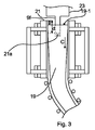
図3は、連続鋳造中の設備7の概略側面図である。容器9aは、溶融金属19で満たされている。溶融金属19は、タンディッシュまたは取瓶23の浸漬ノズル(SEN)21を介して容器9a内に排出される。それ故に,SEN21は、容器9a内の溶融金属19に浸漬されている。溶融金属19は、SEN21の排出開口21aを介して、SEN21から容器9a内に排出される。本明細書において、溶融金属19の表面は、メニスカス19−1と称される。
FIG. 3 is a schematic side view of the equipment 7 during continuous casting. The
容器9aは、溶融金属19を受けるための第1の開口9−1が設けられた第1の側面9fを有する。かくして、容器9aが使用されるときに、第1の側面9fは、典型的に、容器9aの上側側面となる。
The
一実施形態によると、第1の磁気設備10の脚11−2は、第1の側面9fから軸方向の距離dを置いて配設されている。脚11−2は、容器9aの軸方向に対して直交して配設されることが好ましい。一実施形態において、脚の中心は、第1の側面9fから距離dを置いて配設されている。距離dは、第1の側面9fから、容器9a内に収容されている溶融金属19のメニスカス19−1レベルまでの距離よりも大きい。距離dは、第1の側面9fからの、溶融金属19がSEN21によって容器9a内に排出される距離以下であることが好ましい。脚11−2は、第1の磁気設備10という手段によって溶融金属19において効率のよい副次的流れを得るために、この域内のどこにでも配設され得る。かくして、脚は、浸漬ノズルが容器9a内の溶融金属19に浸漬されているところから、半径方向に外向きの位置に配設されていることが好ましい。
According to one embodiment, the legs 11-2 of the first
第1の磁気設備10は、溶融金属19の流れ方向Cに対して第2の磁気設備13の上流に配設され、当該流れ方向は、第1の開口9−1から第2の開口9−2に規定されている。
The first
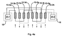
図4aおよび図4bを参照すると、コイル10−3の電力源の連結構成の2つの例の概略図が示される。簡単にするために、たとえば第1の磁気部分のコイル10−3aから10−3hのみが、図4a〜図4bに示されている。図4a〜図4bの例によると、描かれた磁気部分の磁心は、8個のコイルを有する。しかしながら、本開示による磁心は、異なる実施形態において、例えば6、8、9、10、または12個のコイルのいずれかを有し得る。 Referring to FIGS. 4a and 4b, schematic diagrams of two examples of coupling configurations of power sources for coil 10-3 are shown. For simplicity, only the coils 10-3a to 10-3h of the first magnetic part, for example, are shown in FIGS. 4a to 4b. According to the example of FIGS. 4a to 4b, the magnetic core of the depicted magnetic part has eight coils. However, the magnetic core according to the present disclosure may have, for example, any of 6, 8, 9, 10, or 12 coils in different embodiments.
図4aにおいて、電力系統16は、コイル10−3aから10−3hの各々に対し、搬送電流に重畳された交流電流を提供するための電力コンバータ23−1および23−2を有する。隣接するコイル間の位相シフトは、例えば、45または90度であり得る。かくして、隣接するコイル間において位相差が90度である一例によると、コイル10−3aは、0の位相角を有し、コイル10−3bは、90度の位相角を有し、コイル10−3cは、180度の位相角を有し、コイル10−3dは、270度の位相角を有し、コイル10−3eは、0度の位相角を有し、以下同様である。矢印は、この例では直流電流である、搬送電流の極性を表示している。図4aの例において、隣接するコイルには、同じ極性の直流電流が、対の態様で供給される。コイルの対には、一方がコンバータ23−1によって供給され、他方がコンバータ23−2によって供給されるように、供給が行われる。端コイル10−3aおよび10−3hは、同じ極性を有する。それ故に、電力系統16は、第1の磁気部分のコイルのうちの少なくとも2つに対し、相互に異なる極性を有する搬送電流を提供するように構成されている。
In FIG. 4a, the
それぞれ搬送電流および交流電流の極性および位相の多くの変化が、請求項によって提供された範囲内において可能であることに留意されるべきである。 It should be noted that many changes in the polarity and phase of the carrier current and the alternating current, respectively, are possible within the scope provided by the claims.
一般に、重ねられた態様でコイルに提供される具体的な交流電流および搬送電流は、容器9a内の溶融金属の状態と、鋳造管、たとえばSEN21によって提供される溶融金属の流量とに依存する。センサおよびコントローラを有する制御系統が、この目的のために使用される。センサは、例えば、SEN21に、または、容器9aの内部壁に設けられ得る。センサは、溶融金属に関係する1つまたは複数のパラメータ、たとえば、容器9aのプレート9eの温度、容器に提供される溶融金属の流量、または、メニスカスレベルを測定するように配設される。流れ制御電流は、測定された1つまたは複数のパラメータに基づいて制御される。流れ制御は、典型的に、コイルに提供された少なくとも1つの流れ制御電流の位相および振幅のいずれかを制御することを含む。一実施形態では、交流電流および搬送電流のいずれかは、各コイルに対して個々に制御され得る。
In general, the specific alternating current and carrier current provided to the coils in a superimposed manner depends on the state of the molten metal in the
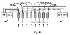
図4bにおいて、別の電力源の構成が示される。この例では、電力系統16が、第1の磁気部分の各コイル10−3aから10−3hに対し、同じ極性を有する搬送電流を提供するように構成されている。図4bの特定の例では、4個のコンバータ23−1、23−2、23−3、および23−4が、この目的のために使用されている。
In FIG. 4b, another power source configuration is shown. In this example, the
発明の概念について、数個の実施形態を参照して、主に上で説明してきた。しかしながら、当該技術において技量を有する者らによって容易に認識されるように、上に開示された実施形態以外の他の実施形態が、添付の特許請求の範囲によって規定される、この発明の範囲内においても等しく可能である。 The inventive concept has mainly been described above with reference to several embodiments. However, other embodiments other than those disclosed above are within the scope of the invention as defined by the appended claims, as will be readily appreciated by those skilled in the art. Is equally possible.
Claims (13)
容器(9a)内に溶融金属(19)を受けるための第1の開口(9−1)、前記容器(9a)から前記溶融金属(19)を排出するための第2の開口(9−2)、および、前記第1の開口(9−1)と前記第2の開口(9−2)との間に延在する本体(9b)を有する、容器(9a)と、
前記本体(9b)に取り付けられている第1の磁気設備(10)であって、脚(10−2)のついた磁心(10−1)、および、前記脚(10−2)の周囲に配設されたコイル(10−3)を有する、第1の磁気設備(10)と、
前記コイル(10−3)の各々に対し、交流電流が搬送電流に重畳された状態で、前記交流電流および前記搬送電流を提供するように構成された電力系統(16)であって、コイル(10−3)に提供された交流電流および搬送電流の各対が、流れ制御電流を形成し、隣接するコイルに提供された流れ制御電流が、互いを基準にして位相シフトされ、それによって、前記容器(9a)内の溶融金属(19)において進行磁場を生成する、電力系統(16)と、
前記本体(9b)に取り付けられた第2の磁気設備(13)であって、前記電力系統(16)が、他の信号が重畳されていない状態で、前記第2の磁気設備(13)に直流電流を供給するように配設される、第2の磁気設備(13)と
を備え、
前記第1の磁気設備(10)が、前記溶融金属(19)の流れ方向(C)に対して前記第2の磁気設備(13)の上流に配設され、前記流れ方向(C)が、前記第1の開口(9−1)から前記第2の開口(9−2)へ規定されている、設備(7)。 Equipment for continuous casting process (7), said equipment (7)
A first opening (9-1) for receiving the molten metal (19) in the container (9a) and a second opening (9-2) for discharging the molten metal (19) from the container (9a) ) And a container (9a) having a body (9b) extending between the first opening (9-1) and the second opening (9-2);
A first magnetic facility (10) attached to the main body (9b), including a magnetic core (10-1) with a leg (10-2) and a periphery of the leg (10-2) A first magnetic facility (10) having a coil (10-3) disposed;
For each of the coils (10-3), an electric power system (16) configured to provide the alternating current and the carrier current in a state where an alternating current is superimposed on the carrier current, Each pair of alternating current and carrier current provided in 10-3) forms a flow control current, and the flow control current provided to adjacent coils is phase shifted with respect to each other, thereby A power system (16) for generating a traveling magnetic field in the molten metal (19) in the container (9a);
A second magnetic facility (13) attached to the main body (9b) , wherein the power system (16) is connected to the second magnetic facility (13) in a state where other signals are not superimposed. A second magnetic facility (13) arranged to supply a direct current,
The first magnetic equipment (10) is disposed upstream of the second magnetic equipment (13) with respect to the flow direction (C) of the molten metal (19), and the flow direction (C) is Equipment (7) defined from the first opening (9-1) to the second opening (9-2).
前記第1の磁気設備(10)の各コイル(10−3)に対し、交流電流が搬送電流に重畳された状態で、前記交流電流および前記搬送電流を提供することであって、コイル(10−3)に提供された交流電流および搬送電流の各対が、流れ制御電流を形成し、隣接するコイル(10−3)に提供された流れ制御電流が、互いを基準にして位相シフトされ、それによって、前記容器(9a)内の前記溶融金属(19)において進行磁場を生成する、交流電流および搬送電流を提供すること
を含む、方法。 A method for flow control of molten metal (19) in a vessel (9a) for a continuous casting process, wherein the vessel (9a) has a first opening for receiving the molten metal (19). (9-1), a second opening (9-2) for discharging the molten metal (19), and the first opening (9-1) and the second opening (9-2). A first magnetic equipment (10) is attached to the main body (9b), and the first magnetic equipment (10) is a leg (10). -2) and a coil (10-3) disposed around the leg (10-2), and an electric power system (16) includes the coil (10). for each of -3), is configured to provide ac current and transportable power flow, the second magnetic equipment (13), said body Attached to 9b), said power system (16), with the other signal is not superimposed, is arranged to supply a direct current to said second magnetic equipment (13), said first A magnetic facility (10) is disposed upstream of the second magnetic facility (13) with respect to the flow direction (C) of the molten metal (19), and the flow direction (C) is the first flow direction (C). A method defined from an opening (9-1) to the second opening (9-2), wherein the method comprises:
For each coil (10-3) of the first magnetic equipment (10), the alternating current and the carrier current are provided in a state where the alternating current is superimposed on the carrier current, and the coil (10 Each pair of alternating current and carrier current provided in -3) forms a flow control current, and the flow control current provided in adjacent coils (10-3) are phase shifted with respect to each other, Providing an alternating current and a carrier current thereby generating a traveling magnetic field in the molten metal (19) in the vessel (9a).
Applications Claiming Priority (1)
| Application Number | Priority Date | Filing Date | Title |
|---|---|---|---|
| PCT/EP2011/073727 WO2013091701A1 (en) | 2011-12-22 | 2011-12-22 | Arrangement and method for flow control of molten metal in a continuous casting process |
Publications (2)
| Publication Number | Publication Date |
|---|---|
| JP2015502261A JP2015502261A (en) | 2015-01-22 |
| JP5745192B2 true JP5745192B2 (en) | 2015-07-08 |
Family
ID=45401084
Family Applications (1)
| Application Number | Title | Priority Date | Filing Date |
|---|---|---|---|
| JP2014547722A Active JP5745192B2 (en) | 2011-12-22 | 2011-12-22 | Equipment and method for flow control of molten metal in continuous casting process |
Country Status (11)
| Country | Link |
|---|---|
| US (1) | US8985189B2 (en) |
| EP (1) | EP2794149B1 (en) |
| JP (1) | JP5745192B2 (en) |
| KR (1) | KR101536882B1 (en) |
| CN (1) | CN103998159B (en) |
| BR (1) | BR112014014324B1 (en) |
| CA (1) | CA2859739C (en) |
| IN (1) | IN2014CN04488A (en) |
| MX (1) | MX2014007567A (en) |
| WO (1) | WO2013091701A1 (en) |
| ZA (1) | ZA201403493B (en) |
Families Citing this family (5)
| Publication number | Priority date | Publication date | Assignee | Title |
|---|---|---|---|---|
| JP6336210B2 (en) | 2014-11-20 | 2018-06-06 | アーベーベー シュヴァイツ アクツィエンゲゼルシャフト | Electromagnetic brake system and molten metal flow control method in metal manufacturing process |
| US9289820B1 (en) * | 2015-04-21 | 2016-03-22 | Ut-Battelle, Llc | Apparatus and method for dispersing particles in a molten material without using a mold |
| EP3415251A1 (en) | 2017-06-16 | 2018-12-19 | ABB Schweiz AG | Electromagnetic brake system and method of controlling an electromagnetic brake system |
| WO2020170836A1 (en) | 2019-02-19 | 2020-08-27 | Jfeスチール株式会社 | Control method for continuous casting machine, control device for continuous casing machine, and manufacturing method for cast slab |
| WO2022138002A1 (en) * | 2020-12-25 | 2022-06-30 | Jfeスチール株式会社 | Continuous casting method for steel |
Family Cites Families (13)
| Publication number | Priority date | Publication date | Assignee | Title |
|---|---|---|---|---|
| JPH05154623A (en) * | 1991-12-04 | 1993-06-22 | Nippon Steel Corp | Method for controlling fluidity of molten steel in mold |
| JPH10305353A (en) * | 1997-05-08 | 1998-11-17 | Nkk Corp | Continuous molding of steel |
| KR100376504B1 (en) * | 1998-08-04 | 2004-12-14 | 주식회사 포스코 | Continuous casting method and continuous casting apparatus used |
| JP2000351048A (en) * | 1999-06-09 | 2000-12-19 | Kawasaki Steel Corp | Method and apparatus for continuously casting metal |
| CA2646757A1 (en) * | 2000-07-10 | 2002-01-10 | Jfe Steel Corporation | Method and apparatus for continuous casting of metals |
| SE523881C2 (en) * | 2001-09-27 | 2004-05-25 | Abb Ab | Device and method of continuous casting |
| JP4263396B2 (en) * | 2001-11-30 | 2009-05-13 | Jfeスチール株式会社 | Steel continuous casting method and equipment |
| EP1623777B1 (en) * | 2003-04-11 | 2007-04-18 | JFE Steel Corporation | Continuous casting method for steel |
| JP4348988B2 (en) * | 2003-04-11 | 2009-10-21 | Jfeスチール株式会社 | Steel continuous casting method |
| US20050045303A1 (en) * | 2003-08-29 | 2005-03-03 | Jfe Steel Corporation, A Corporation Of Japan | Method for producing ultra low carbon steel slab |
| WO2008004969A1 (en) * | 2006-07-06 | 2008-01-10 | Abb Ab | Method and apparatus for controlling the flow of molten steel in a mould |
| DE102007038281B4 (en) * | 2007-08-03 | 2009-06-18 | Forschungszentrum Dresden - Rossendorf E.V. | Method and device for the electromagnetic stirring of electrically conductive liquids |
| JP4807462B2 (en) * | 2009-11-10 | 2011-11-02 | Jfeスチール株式会社 | Steel continuous casting method |
-
2011
- 2011-12-22 BR BR112014014324-2A patent/BR112014014324B1/en active IP Right Grant
- 2011-12-22 WO PCT/EP2011/073727 patent/WO2013091701A1/en active Application Filing
- 2011-12-22 IN IN4488CHN2014 patent/IN2014CN04488A/en unknown
- 2011-12-22 JP JP2014547722A patent/JP5745192B2/en active Active
- 2011-12-22 MX MX2014007567A patent/MX2014007567A/en active IP Right Grant
- 2011-12-22 CN CN201180075422.XA patent/CN103998159B/en active Active
- 2011-12-22 EP EP11799721.3A patent/EP2794149B1/en active Active
- 2011-12-22 KR KR1020147017125A patent/KR101536882B1/en active IP Right Grant
- 2011-12-22 CA CA2859739A patent/CA2859739C/en active Active
-
2014
- 2014-05-14 ZA ZA2014/03493A patent/ZA201403493B/en unknown
- 2014-06-20 US US14/310,236 patent/US8985189B2/en active Active
Also Published As
| Publication number | Publication date |
|---|---|
| KR101536882B1 (en) | 2015-07-14 |
| US8985189B2 (en) | 2015-03-24 |
| ZA201403493B (en) | 2015-06-24 |
| BR112014014324B1 (en) | 2018-07-03 |
| EP2794149B1 (en) | 2015-06-24 |
| CN103998159A (en) | 2014-08-20 |
| CA2859739A1 (en) | 2013-06-27 |
| CN103998159B (en) | 2016-04-27 |
| BR112014014324A2 (en) | 2017-06-13 |
| US20140299288A1 (en) | 2014-10-09 |
| WO2013091701A1 (en) | 2013-06-27 |
| KR20140095100A (en) | 2014-07-31 |
| CA2859739C (en) | 2016-03-22 |
| IN2014CN04488A (en) | 2015-09-11 |
| JP2015502261A (en) | 2015-01-22 |
| EP2794149A1 (en) | 2014-10-29 |
| MX2014007567A (en) | 2014-10-17 |
Similar Documents
| Publication | Publication Date | Title |
|---|---|---|
| JP5745192B2 (en) | Equipment and method for flow control of molten metal in continuous casting process | |
| US7735544B2 (en) | Method and system of electromagnetic stirring for continuous casting of medium and high carbon steels | |
| EP2038081B1 (en) | Method and apparatus for controlling the flow of molten steel in a mould | |
| RU2457064C1 (en) | Method of continuous and semicontinuous casing of aluminium alloys and device to this end | |
| US20030106667A1 (en) | Method and device for continuous casting of metals in a mold | |
| CN104107891A (en) | Electromagnetic sensor of electromagnetic stirring device of slab continuous-casting crystallizer | |
| US20070151414A1 (en) | Systems and methods of electromagnetic influence on electroconducting continuum | |
| WO2013133318A1 (en) | Titanium melting device | |
| KR101332209B1 (en) | Method and device for the continuous casting of preliminary steel sections, in particular preliminary double-t sections | |
| CN101259523B (en) | Electro-magnetic braking device for controlling molten metal flow in continuous cast crystallizer | |
| CN109909467B (en) | Layered coil crystallizer electromagnetic stirrer | |
| CN101720262A (en) | Steel continuous casting method and in-mold molten steel fluidity controller | |
| RU2574556C1 (en) | Device and method of melted metal flow regulation during continuous casting | |
| JP2010017749A (en) | Melting furnace, continuous casting apparatus, and casting method for continuous casting apparatus | |
| US7237597B2 (en) | Method and device for continuous casting of metals in a mold | |
| JP2004058092A (en) | Continuous casting method for steel | |
| PESTEANU | The washing effect in electromagnetic rotational stirrers for continuous casting | |
| JP2003275849A (en) | Method for producing continuously cast slab | |
| JP2004042065A (en) | Electromagnetic stirring device |
Legal Events
| Date | Code | Title | Description |
|---|---|---|---|
| A975 | Report on accelerated examination |
Free format text: JAPANESE INTERMEDIATE CODE: A971005 Effective date: 20141029 |
|
| A131 | Notification of reasons for refusal |
Free format text: JAPANESE INTERMEDIATE CODE: A131 Effective date: 20150106 |
|
| A521 | Request for written amendment filed |
Free format text: JAPANESE INTERMEDIATE CODE: A523 Effective date: 20150119 |
|
| A521 | Request for written amendment filed |
Free format text: JAPANESE INTERMEDIATE CODE: A523 Effective date: 20150313 |
|
| TRDD | Decision of grant or rejection written | ||
| A01 | Written decision to grant a patent or to grant a registration (utility model) |
Free format text: JAPANESE INTERMEDIATE CODE: A01 Effective date: 20150407 |
|
| A61 | First payment of annual fees (during grant procedure) |
Free format text: JAPANESE INTERMEDIATE CODE: A61 Effective date: 20150430 |
|
| R150 | Certificate of patent or registration of utility model |
Ref document number: 5745192 Country of ref document: JP Free format text: JAPANESE INTERMEDIATE CODE: R150 |
|
| R250 | Receipt of annual fees |
Free format text: JAPANESE INTERMEDIATE CODE: R250 |
|
| S111 | Request for change of ownership or part of ownership |
Free format text: JAPANESE INTERMEDIATE CODE: R313113 |
|
| S531 | Written request for registration of change of domicile |
Free format text: JAPANESE INTERMEDIATE CODE: R313531 |
|
| R350 | Written notification of registration of transfer |
Free format text: JAPANESE INTERMEDIATE CODE: R350 |
|
| R250 | Receipt of annual fees |
Free format text: JAPANESE INTERMEDIATE CODE: R250 |
|
| R250 | Receipt of annual fees |
Free format text: JAPANESE INTERMEDIATE CODE: R250 |
|
| R250 | Receipt of annual fees |
Free format text: JAPANESE INTERMEDIATE CODE: R250 |
|
| R250 | Receipt of annual fees |
Free format text: JAPANESE INTERMEDIATE CODE: R250 |
|
| R250 | Receipt of annual fees |
Free format text: JAPANESE INTERMEDIATE CODE: R250 |