JP5725877B2 - Power supply apparatus, crane, and power supply method. - Google Patents
Power supply apparatus, crane, and power supply method. Download PDFInfo
- Publication number
- JP5725877B2 JP5725877B2 JP2011009245A JP2011009245A JP5725877B2 JP 5725877 B2 JP5725877 B2 JP 5725877B2 JP 2011009245 A JP2011009245 A JP 2011009245A JP 2011009245 A JP2011009245 A JP 2011009245A JP 5725877 B2 JP5725877 B2 JP 5725877B2
- Authority
- JP
- Japan
- Prior art keywords
- power
- crane
- load
- power supply
- storage battery
- Prior art date
- Legal status (The legal status is an assumption and is not a legal conclusion. Google has not performed a legal analysis and makes no representation as to the accuracy of the status listed.)
- Active
Links
- 238000000034 method Methods 0.000 title claims description 15
- 238000004804 winding Methods 0.000 claims description 68
- 238000007599 discharging Methods 0.000 claims description 21
- 230000001133 acceleration Effects 0.000 claims description 20
- 230000008859 change Effects 0.000 description 11
- 230000005540 biological transmission Effects 0.000 description 8
- 239000013589 supplement Substances 0.000 description 5
- 238000010586 diagram Methods 0.000 description 3
- 230000007613 environmental effect Effects 0.000 description 2
- 230000005389 magnetism Effects 0.000 description 2
- 238000010248 power generation Methods 0.000 description 2
- 239000003795 chemical substances by application Substances 0.000 description 1
- 230000005611 electricity Effects 0.000 description 1
- 238000009434 installation Methods 0.000 description 1
- 238000004519 manufacturing process Methods 0.000 description 1
- 239000000047 product Substances 0.000 description 1
- 230000004044 response Effects 0.000 description 1
- 230000032258 transport Effects 0.000 description 1
Images


Classifications
-
- B—PERFORMING OPERATIONS; TRANSPORTING
- B66—HOISTING; LIFTING; HAULING
- B66C—CRANES; LOAD-ENGAGING ELEMENTS OR DEVICES FOR CRANES, CAPSTANS, WINCHES, OR TACKLES
- B66C13/00—Other constructional features or details
- B66C13/12—Arrangements of means for transmitting pneumatic, hydraulic, or electric power to movable parts of devices
-
- B—PERFORMING OPERATIONS; TRANSPORTING
- B66—HOISTING; LIFTING; HAULING
- B66C—CRANES; LOAD-ENGAGING ELEMENTS OR DEVICES FOR CRANES, CAPSTANS, WINCHES, OR TACKLES
- B66C19/00—Cranes comprising trolleys or crabs running on fixed or movable bridges or gantries
- B66C19/007—Cranes comprising trolleys or crabs running on fixed or movable bridges or gantries for containers
-
- H—ELECTRICITY
- H01—ELECTRIC ELEMENTS
- H01M—PROCESSES OR MEANS, e.g. BATTERIES, FOR THE DIRECT CONVERSION OF CHEMICAL ENERGY INTO ELECTRICAL ENERGY
- H01M10/00—Secondary cells; Manufacture thereof
- H01M10/42—Methods or arrangements for servicing or maintenance of secondary cells or secondary half-cells
- H01M10/44—Methods for charging or discharging
-
- H—ELECTRICITY
- H02—GENERATION; CONVERSION OR DISTRIBUTION OF ELECTRIC POWER
- H02J—CIRCUIT ARRANGEMENTS OR SYSTEMS FOR SUPPLYING OR DISTRIBUTING ELECTRIC POWER; SYSTEMS FOR STORING ELECTRIC ENERGY
- H02J7/00—Circuit arrangements for charging or depolarising batteries or for supplying loads from batteries
- H02J7/34—Parallel operation in networks using both storage and other dc sources, e.g. providing buffering
-
- Y—GENERAL TAGGING OF NEW TECHNOLOGICAL DEVELOPMENTS; GENERAL TAGGING OF CROSS-SECTIONAL TECHNOLOGIES SPANNING OVER SEVERAL SECTIONS OF THE IPC; TECHNICAL SUBJECTS COVERED BY FORMER USPC CROSS-REFERENCE ART COLLECTIONS [XRACs] AND DIGESTS
- Y02—TECHNOLOGIES OR APPLICATIONS FOR MITIGATION OR ADAPTATION AGAINST CLIMATE CHANGE
- Y02E—REDUCTION OF GREENHOUSE GAS [GHG] EMISSIONS, RELATED TO ENERGY GENERATION, TRANSMISSION OR DISTRIBUTION
- Y02E60/00—Enabling technologies; Technologies with a potential or indirect contribution to GHG emissions mitigation
- Y02E60/10—Energy storage using batteries
Landscapes
- Engineering & Computer Science (AREA)
- Mechanical Engineering (AREA)
- Power Engineering (AREA)
- Manufacturing & Machinery (AREA)
- Chemical & Material Sciences (AREA)
- Chemical Kinetics & Catalysis (AREA)
- Electrochemistry (AREA)
- General Chemical & Material Sciences (AREA)
- Charge And Discharge Circuits For Batteries Or The Like (AREA)
- Secondary Cells (AREA)
- Control And Safety Of Cranes (AREA)
Description
本発明は、例えば、箱型形状のコンテナ(吊荷)が多数設置される港湾のコンテナヤードにてコンテナを搬送するクレーンの電力供給装置、クレーン、及び電力供給方法に関するものである。 The present invention relates to a power supply apparatus, a crane, and a power supply method for a crane that transports containers in a container yard of a harbor where a large number of box-shaped containers (suspended loads) are installed, for example.
港湾等のコンテナヤードでは、船舶へ積み込む前のコンテナや、船舶から積み下ろされたコンテナが多数設置されている。これらコンテナは、上方へ複数積み上げられた段積みコンテナとされ、各段積みコンテナが所定配列に従ってレーンごとに並べられている。各レーンには、レーンを跨ぐように、RTG(Rubber Tired Gantry crane)等の自走式の門型クレーンが配置されている。この門型クレーンによって、レーン内を走行するトレーラやAGV(Automatic Guided Vehicle)とのコンテナの受け渡しが行われ、また、レーン内のコンテナの設置等が行われる。 In a container yard such as a harbor, a number of containers before being loaded onto a ship and containers unloaded from the ship are installed. These containers are a plurality of stacked containers stacked upward, and each stacked container is arranged for each lane according to a predetermined arrangement. In each lane, a self-propelled portal crane such as an RTG (Rubber Tired Gantry crane) is disposed so as to straddle the lane. With this portal crane, the container is transferred to and from the trailer traveling in the lane and AGV (Automatic Guided Vehicle), and the container is installed in the lane.
このようなRTG等のクレーンは、従来、クレーンに搭載されたエンジン発電機にて発電し、クレーンの走行モータや荷役モータに電力を供給している。また、近年の環境負荷低減の要請から、エンジン発電機に加えてバッテリを搭載したハイブリッド電源方式が実用化されつつある。さらに環境負荷の低減を進める方式として、エンジン発電機を廃し、地上に設けた給電源から給電ケーブルおよびケーブルリールを介してクレーンに電力を供給するケーブルリール式地上給電方式がある。 Conventionally, such cranes as RTGs generate electricity with an engine generator mounted on the crane and supply electric power to a traveling motor and a cargo handling motor of the crane. In addition, in recent years, a hybrid power supply system in which a battery is mounted in addition to an engine generator is being put into practical use in response to a request for reducing environmental load. Further, as a method for further reducing the environmental load, there is a cable reel type ground power feeding method in which an engine generator is eliminated and power is supplied to a crane from a power supply provided on the ground via a power feeding cable and a cable reel.
特許文献1には、商用電源と蓄電装置とからの給電によって駆動するクレーンが記載されている。
特許文献1に記載されているクレーンは、蓄電装置の蓄電量が第1閾値を上回っている場合、高圧領域及び低圧領域共に、蓄電装置単体でモータを駆動させ、蓄電装置の蓄電量が第1閾値を下回っている場合は、蓄電装置からの電力と商用電源からの電力の併用によってモータを駆動させ、蓄電装置の蓄電量が第1閾値よりも低い第2閾値を下回っている場合は、商用電源からの電力のみによってモータを駆動させる。
In the crane described in
ここで、RTG等のクレーンは、吊荷の巻き上げに要する電力が例えば150kW(過負荷耐量180%時最大270kW)、トロリの横行走行に要する電力が例えば22kW(過負荷耐量200%時最大44kW)、その他ベースロードが最大の場合に要する電力が例えば35kW程度の負荷に対する電力を必要とするため、合計最大350kW程度の電力を必要とする。 Here, for a crane such as RTG, the electric power required for lifting the suspended load is 150 kW (maximum 270 kW when the overload capacity is 180%), and the electric power required for traversing the trolley is 22 kW (maximum 44 kW when the overload capacity is 200%). In addition, since the power required when the base load is maximum requires power for a load of about 35 kW, for example, a total power of about 350 kW is required.
一方、吊荷を巻き下げる場合、クレーンは、発電機の振る舞いをし、商用電源へ電力を回生する。 On the other hand, when unloading a suspended load, the crane behaves like a generator and regenerates power to a commercial power source.
このように、クレーンによる電力の消費と発電とを平均すると数十kW程度となることから、クレーンによっては、負荷変動が大きくなる場合もある。 Thus, since the average of power consumption and power generation by the crane is about several tens of kW, the load fluctuation may be increased depending on the crane.
しかし、特許文献1に記載のクレーンは、蓄電装置で補えない電力が商用電源から供給されるので、商用電源から供給される電力は場面に応じて変動するため、RTG等に適用する場合は、高圧電力(例えば、AC6600V)となることを想定して、商用電源からの給電のための電源設備等を構成しなければならない。そして、クレーンの電力変動が大きい場合は、さらに過剰な電源設備を必要とする。
However, since the crane described in
本発明は、このような事情に鑑みてなされたものであって、商用電源からクレーンへ供給する電力を低電力とし低圧送電を可能にすることができる、電力供給装置、クレーン、及び電力供給方法を提供することを目的とする。 The present invention has been made in view of such circumstances, and an electric power supply device, a crane, and an electric power supply method that can reduce the electric power supplied from the commercial power source to the crane and enable low-voltage power transmission. The purpose is to provide.
上記課題を解決するために、本発明の電力供給装置、クレーン、及び電力供給方法は以下の手段を採用する。 In order to solve the above problems, the power supply device, the crane, and the power supply method of the present invention employ the following means.
すなわち、本発明に係る電力供給装置は、充放電可能であり、クレーンの電力負荷に電力を供給するために該クレーンに備えられる蓄電池と、商用電源から予め定められた電力の供給を受ける受電手段と、前記クレーンの電力負荷が消費する電力と前記商用電源から供給される電力との電力差を算出する算出手段と、前記算出手段によって算出された電力差に応じた電力を前記蓄電池から充放電させる制御手段と、を備え、前記クレーンは、吊荷を巻き上げる巻き動作における加速度を変化させることで、前記クレーンの電力負荷で消費される電力を抑制する巻き動作を行い、前記蓄電池の電力容量は、前記巻き動作によって抑制された電力に基づく。 In other words, the power supply device according to the present invention is chargeable / dischargeable, a storage battery provided in the crane for supplying power to the power load of the crane, and a power receiving means for receiving a predetermined power supply from a commercial power source. Calculating means for calculating a power difference between the power consumed by the power load of the crane and the power supplied from the commercial power source, and charging / discharging the storage battery with power corresponding to the power difference calculated by the calculating means Control means, and the crane performs a winding operation to suppress power consumed by the power load of the crane by changing an acceleration in a winding operation to wind up the suspended load, and the power capacity of the storage battery is , Based on the power suppressed by the winding operation .
本発明によれば、本発明の電力供給装置は、充放電可能であり、クレーンの電力負荷に電力を供給するために該クレーンに備えられる蓄電池と、商用電源から予め定められた電力の供給を受ける受電手段と、を備える。
すなわち、クレーンは、クレーンに備えられた蓄電池から放電される電力と商用電源から供給される電力とでクレーンの電力負荷を駆動させる。なお、電力負荷とは、クレーンを移動させる車輪を回転させるためのモータや補機等である。
According to the present invention, the power supply device of the present invention is chargeable / dischargeable, and supplies a predetermined power from a storage battery provided in the crane and a commercial power source to supply power to the power load of the crane. Receiving power receiving means.
That is, the crane drives the power load of the crane with electric power discharged from a storage battery provided in the crane and electric power supplied from a commercial power source. The electric power load is a motor, an auxiliary machine, or the like for rotating a wheel that moves a crane.
そして、算出手段によって、クレーンの電力負荷が消費する電力と商用電源から供給される電力との電力差が算出され、制御手段によって、算出手段で算出された電力差に応じた電力が蓄電池から充放電される。 Then, the power difference between the power consumed by the crane's power load and the power supplied from the commercial power source is calculated by the calculating means, and the power corresponding to the power difference calculated by the calculating means is charged from the storage battery by the control means. Discharged.
このため、本発明は、商用電源から供給される予め定められた電力を低くしても(例えば45kW)、蓄電池から放電される電力が商用電源から供給される電力を補うこととなる。従って、本発明は、商用電源からクレーンへ供給する電力を低電力とし低圧送電を可能にすることができる。
また、本発明の電力供給装置は、クレーンが、吊荷を巻き上げる巻き動作における加速度を変化させることで、電力負荷で消費される電力を抑制する巻き動作を行い、蓄電池の電力容量は、巻き動作によって抑制された電力に基づく。
本発明によれば、クレーンの巻き動作の加速度に応じて消費電力が過大となる場合があるため、巻き動作の加速度を変化させることで、過大な消費電力の発生を抑制させる。これにより、本発明は、蓄電池の電力容量を巻き動作によって抑制された電力に基づいて決定することができるので、より電力容量が低い蓄電池を用いることができる。
For this reason, in the present invention, even if the predetermined power supplied from the commercial power source is lowered (for example, 45 kW), the power discharged from the storage battery supplements the power supplied from the commercial power source. Therefore, according to the present invention, the power supplied from the commercial power source to the crane can be reduced to enable low-voltage power transmission.
Further, the power supply device of the present invention performs a winding operation that suppresses the power consumed by the power load by changing the acceleration in the winding operation in which the crane winds up the suspended load, and the power capacity of the storage battery is the winding operation. Based on the power suppressed by.
According to the present invention, since the power consumption may become excessive depending on the acceleration of the crane winding operation, the generation of excessive power consumption is suppressed by changing the acceleration of the winding operation. Thereby, since this invention can determine the power capacity of a storage battery based on the electric power suppressed by winding operation | movement, a storage battery with lower power capacity can be used.
また、本発明に係る電力供給装置は、発電機を備えたクレーン又は既設の発電機を廃したクレーンの電力負荷に交流電力を供給する電力供給装置であって、充放電可能であり、前記クレーンの電力負荷に電力を供給するために前記クレーンに備えられる蓄電池と、商用電源から予め定められた電力の供給を受ける受電手段と、前記クレーンの電力負荷が消費する電力と前記商用電源から供給される電力との電力差を算出する算出手段と、前記算出手段によって算出された電力差に応じた電力を前記蓄電池から充放電させる制御手段と、前記クレーンの電力負荷への給電路へ前記蓄電池及び前記受電手段からの直流電力を交流電力に変換し供給する供給手段と、を備え、前記クレーンは、吊荷を巻き上げる巻き動作における加速度を変化させることで、前記クレーンの電力負荷で消費される電力を抑制する巻き動作を行い、前記蓄電池の電力容量は、前記巻き動作によって抑制された電力に基づく。 Moreover, the power supply device according to the present invention is a power supply device that supplies AC power to a power load of a crane equipped with a generator or a crane that has abandoned an existing generator, and is chargeable / dischargeable. A storage battery provided in the crane for supplying power to the power load, power receiving means for receiving a predetermined power supply from a commercial power source, power consumed by the crane power load and the commercial power source Calculating means for calculating a power difference from the power to be stored, control means for charging / discharging power from the storage battery according to the power difference calculated by the calculating means, the storage battery and a power supply path to the power load of the crane and a supply means for supplying converts DC power into AC power from the power receiving means, said crane, to vary the acceleration in winding operation to wind the suspended load And in performs a suppressing winding operation the power consumed by the power load of the crane, the power capacity of the battery is based on a power that is suppressed by the winding operation.
本発明によれば、本発明の電力供給装置は、発電機を備えたクレーン又は既設の発電機を廃したクレーンの電力負荷に交流電力を供給するためのものであり、充放電可能であり、クレーンの電力負荷に電力を供給するためにクレーンに備えられる蓄電池と、商用電源から予め定められた電力の供給を受ける受電手段と、クレーンの電力負荷への給電路へ蓄電池及び受電手段からの直流電力を交流電力に変換し供給する供給手段と、を備える。
そして、算出手段によって、クレーンの電力負荷が消費する電力と商用電源から供給される電力との電力差が算出され、制御手段によって、算出手段で算出された電力差に応じた電力が蓄電池から充放電される。
According to the present invention, the power supply device of the present invention is for supplying AC power to a power load of a crane equipped with a generator or a crane that has abolished an existing generator, and is chargeable / dischargeable. A storage battery provided in the crane for supplying power to the power load of the crane, a power receiving means for receiving a predetermined power supply from a commercial power source, and a direct current from the storage battery and the power receiving means to the power supply path to the power load of the crane Supply means for converting electric power into AC electric power and supplying it.
Then, the power difference between the power consumed by the crane's power load and the power supplied from the commercial power source is calculated by the calculating means, and the power corresponding to the power difference calculated by the calculating means is charged from the storage battery by the control means. Discharged.
すなわち、本発明に係る電力供給装置は、発電機によって電力負荷へ電力を供給していた既存のクレーンの電力負荷への給電路へ接続されることによって、該既存のクレーンの電力負荷を、蓄電池と商用電源から供給される電力によって駆動させることができる。 That is, the power supply device according to the present invention is connected to the power supply path to the power load of the existing crane that has been supplying power to the power load by the generator, so that the power load of the existing crane is stored in the storage battery. And can be driven by electric power supplied from a commercial power source.
そして、本発明は、商用電源から供給される予め定められた電力を低くしても(例えば45kW)、蓄電池から放電される電力が商用電源から供給される電力を補うこととなる。従って、本発明は、商用電源からクレーンへ供給する電力を低電力とし低圧送電を可能にすることができる。 In the present invention, even if the predetermined power supplied from the commercial power source is lowered (for example, 45 kW), the power discharged from the storage battery supplements the power supplied from the commercial power source. Therefore, according to the present invention, the power supplied from the commercial power source to the crane can be reduced to enable low-voltage power transmission.
また、本発明の電力供給装置は、前記クレーンが、他のレーンへ移動可能とされ、前記制御手段は、前記クレーンがレーン間を移動する場合、前記商用電源から供給される電力はないものとして前記蓄電池を充放電させる。 Further, in the power supply apparatus of the present invention, the crane can be moved to another lane, and the control means assumes that no power is supplied from the commercial power source when the crane moves between lanes. The storage battery is charged and discharged.
本発明によれば、クレーンがレーン間を移動する場合、商用電源から供給される電力はないものとして蓄電池を充放電させるので、クレーンを他のレーンへ移動させるために商用電源から電力を供給されない状態となっても、クレーンを他のレーンへ移動させることができる。なお、蓄電池は、クレーンのレーン間の移動によって消費される電力を賄える電力容量を有するものが予め選択される。 According to the present invention, when the crane moves between lanes, the storage battery is charged / discharged on the assumption that there is no electric power supplied from the commercial power source, so that no electric power is supplied from the commercial power source to move the crane to another lane. Even in this state, the crane can be moved to another lane. A storage battery having a power capacity that can cover power consumed by movement between lanes of the crane is selected in advance.
また、本発明の電力供給装置は、前記商用電源から供給される電力が、前記予め定められた電力以下で可変とされる。 In the power supply apparatus of the present invention, the power supplied from the commercial power source is variable below the predetermined power.
本発明によれば、商用電源から供給される電力が、予め定められた電力以下で可変とされるので、電力負荷で消費される電力が少ない場合等に、商用電源から供給される電力をより低くすることができる。 According to the present invention, since the power supplied from the commercial power source is variable below a predetermined power, the power supplied from the commercial power source is more reduced when the power consumed by the power load is small. Can be lowered.
また、本発明の電力供給装置は、前記制御手段が、前記蓄電池の充電状態の履歴に基づいて、前記商用電源から供給される電力を変化させる。 In the power supply apparatus of the present invention, the control unit changes the power supplied from the commercial power source based on the history of the state of charge of the storage battery.
本発明によれば、蓄電池の充電状態の履歴に基づいて、商用電源から供給される電力を変化させるので、蓄電池の充電量が高い場合に、商用電源から供給される電力をより低くすることができる。 According to the present invention, since the electric power supplied from the commercial power supply is changed based on the charge state history of the storage battery, the electric power supplied from the commercial power supply can be lowered when the storage battery is charged to a high amount. it can.
また、本発明の電力供給装置は、前記制御手段が、前記クレーンの前記電力負荷へ供給する電力の履歴に基づいて、前記商用電源から供給される電力を変化させる。 Moreover, the electric power supply apparatus of this invention changes the electric power supplied from the said commercial power source based on the log | history of the electric power which the said control means supplies to the said electric power load of the said crane .
本発明によれば、クレーンの電力負荷へ供給する電力の履歴に基づいて、商用電源から供給される電力を変化させるので、電力負荷で消費される電力が少ない場合に、商用電源から供給される電力をより低くすることができる。 According to the present invention, since the power supplied from the commercial power source is changed based on the history of the power supplied to the power load of the crane, the power is supplied from the commercial power source when the power consumed by the power load is small. Electric power can be made lower.
一方、本発明に係るクレーンは、上記記載の電力供給装置と、前記電力供給装置から供給される電力によって駆動する電力負荷と、を備える。 On the other hand, a crane according to the present invention includes the above-described power supply device and a power load that is driven by power supplied from the power supply device.
本発明によれば、上記記載の電力供給装置を備えるので、商用電源から供給される予め定められた電力を低くしても(例えば45kW)、蓄電池から放電される電力が商用電源から供給される電力を補うこととなる。従って、本発明は、商用電源からクレーンへ供給する電力を低電力とし低圧送電を可能にすることができる。 According to the present invention, since the power supply device described above is provided, even if the predetermined power supplied from the commercial power source is lowered (for example, 45 kW), the power discharged from the storage battery is supplied from the commercial power source. Power will be supplemented. Therefore, according to the present invention, the power supplied from the commercial power source to the crane can be reduced to enable low-voltage power transmission.
さらに、本発明に係る電力供給方法は、充放電可能であり、クレーンの電力負荷に電力を供給するために該クレーンに備えられる蓄電池と、商用電源から予め定められた電力の供給を受ける受電手段と、を備えた前記クレーンの電力負荷に電力を供給する電力供給方法であって、前記クレーンの電力負荷が消費する電力と前記商用電源から供給される電力との電力差を算出する第1工程と、前記第1工程によって算出された電力差に応じた電力を前記蓄電池から充放電させる第2工程と、を含み、前記クレーンは、吊荷を巻き上げる巻き動作における加速度を変化させることで、前記クレーンの電力負荷で消費される電力を抑制する巻き動作を行い、前記蓄電池の電力容量は、前記巻き動作によって抑制された電力に基づく。 Furthermore, the power supply method according to the present invention is chargeable / dischargeable, a storage battery provided in the crane for supplying power to the power load of the crane, and power receiving means for receiving a predetermined power supply from a commercial power source And a power supply method for supplying power to the power load of the crane, comprising: calculating a power difference between power consumed by the power load of the crane and power supplied from the commercial power source When, viewed it contains a second step, the for charging and discharging the power according to the power difference calculated by said first step from said battery, said crane, by changing the acceleration of the winding operation to wind the suspended load, A winding operation that suppresses the power consumed by the power load of the crane is performed, and the power capacity of the storage battery is based on the power suppressed by the winding operation .
本発明によれば、本発明は、商用電源から供給される予め定められた電力を低くしても(例えば45kW)、蓄電池から放電される電力が商用電源から供給される電力を補うこととなる。従って、本発明は、商用電源からクレーンへ供給する電力を低電力とし低圧送電を可能にすることができる。 According to the present invention, even if the predetermined power supplied from the commercial power source is lowered (for example, 45 kW), the power discharged from the storage battery supplements the power supplied from the commercial power source. . Therefore, according to the present invention, the power supplied from the commercial power source to the crane can be reduced to enable low-voltage power transmission.
また、本発明に係る電力供給方法は、充放電可能であり、クレーンの電力負荷に電力を供給するために該クレーンに備えられる蓄電池と、商用電源から予め定められた電力の供給を受ける受電手段と、前記クレーンの電力負荷への給電路へ前記蓄電池及び前記受電手段からの直流電力を交流電力に変換し供給する供給手段と、を備え、発電機を備えたクレーン又は既設の発電機を廃した前記クレーンの電力負荷に交流電力を供給するための電力供給装置の電力供給方法であって、前記クレーンの電力負荷が消費する電力と前記商用電源から供給される電力との電力差を算出する第1工程と、前記第1工程によって算出された電力差に応じた電力を前記蓄電池から充放電させる第2工程と、を含み、前記クレーンは、吊荷を巻き上げる巻き動作における加速度を変化させることで、前記クレーンの電力負荷で消費される電力を抑制する巻き動作を行い、前記蓄電池の電力容量は、前記巻き動作によって抑制された電力に基づく。 Further, the power supply method according to the present invention is chargeable / dischargeable, a storage battery provided in the crane for supplying power to the power load of the crane, and a power receiving means for receiving a predetermined power supply from a commercial power source. And a supply means for converting the DC power from the storage battery and the power receiving means to supply AC power to the power supply path to the power load of the crane, and disposing the crane equipped with the generator or the existing generator A power supply method for a power supply device for supplying AC power to the power load of the crane, wherein a power difference between power consumed by the power load of the crane and power supplied from the commercial power source is calculated. a first step, the saw including a second step, the for charging and discharging the power according to the power difference calculated from the battery by the first step, the crane, the winding operation of winding up a suspended load By varying the definitive acceleration performs suppresses winding operation the power consumed by the power load of the crane, the power capacity of the battery is based on a power that is suppressed by the winding operation.
本発明によれば、発電機によって電力負荷へ電力を供給していた既存のクレーンの給電路へ本発明に係る電力供給装置を接続することによって、該既存のクレーンは、蓄電池と商用電源から供給される電力によって、電力負荷を駆動させることができる。
そして、本発明は、商用電源から供給される予め定められた電力を低くしても(例えば45kW)、蓄電池から放電される電力が商用電源から供給される電力を補うこととなる。従って、本発明は、商用電源からクレーンへ供給する電力を低電力とし低圧送電を可能にすることができる。
According to the present invention, the existing crane is supplied from the storage battery and the commercial power source by connecting the power supply device according to the present invention to the power supply path of the existing crane that is supplying power to the power load by the generator. The electric load can be driven by the generated electric power.
In the present invention, even if the predetermined power supplied from the commercial power source is lowered (for example, 45 kW), the power discharged from the storage battery supplements the power supplied from the commercial power source. Therefore, according to the present invention, the power supplied from the commercial power source to the crane can be reduced to enable low-voltage power transmission.
本発明によれば、商用電源からクレーンへ供給する電力を低電力とし低圧送電を可能にすることができる、という優れた効果を有する。 According to the present invention, the power supplied from the commercial power source to the crane can be reduced to enable low-voltage power transmission.
以下に、本発明に係る電力供給装置、クレーン、クレーンの電力供給方法の一実施形態について、図面を参照して説明する。 EMBODIMENT OF THE INVENTION Below, one Embodiment of the electric power supply apparatus which concerns on this invention, a crane, and the electric power supply method of a crane is described with reference to drawings.
〔第1実施形態〕
以下、本発明の第1実施形態について説明する。
[First Embodiment]
The first embodiment of the present invention will be described below.
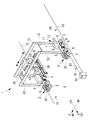
図1は、本第1実施形態にかかるクレーン1を示している。
図1には、レーンRの走行方向Xに設置されたクレーン1が示されている。クレーン1は、地上に設置された給電ボックス31から供給された電力によって動作する地上給電方式の電動クレーンとされており、エンジン発電機を備えていない。また、クレーン1は、クレーン用給電ケーブルリール装置(以下、単に「ケーブルリール装置」という。)2を備えている。
FIG. 1 shows a
FIG. 1 shows a
クレーン1は、いわゆるRTG(Rubber Tired Gantry crane)とされ、複数の車輪(ゴムタイヤ)3によって自走する門型のクレーンとされている。クレーン1は、複数のコンテナ(以下、「吊荷」という。)が上方に段積みされた段積み吊荷が所定配列をもって設置されたレーンRを跨ぐように配置され、レーンRの長手方向(走行方向X)に走行する。
The
クレーン1は、各脚部11に4つの走行装置5を備えており、各走行装置5に4つの車輪3が設けられている。走行装置5は、走行制御装置7によって、その駆動が制御されるようになっている。走行装置5には、オートステアセンサ6が設けられている。このオートステアセンサ6は、レーンRの長手方向に敷設された磁気ガイドライン15からの磁気を検出するようになっており、これにより、クレーン1を走行方向Xに自動で直進運転できるようになっている。
The
左右方向である走行方向Xに隣り合う走行装置5は、下梁9によって連結されており、この下梁9上に走行制御装置7が設置されている。ここで、左右とはクレーン1の走行方向を意味し、前後とはトロリ20の移動方向(横行方向Y)を意味する。これは、トロリ20に設置された運転室22内のオペレータの姿勢を基準として定められたものである。
The traveling
下梁9の中央には、下方に向けた状態のベイセンサ8が設けられている。このベイセンサ8は、設置された吊荷の左右方向の単位であるベイ毎に敷設された磁石16からの磁気を検出するようになっており、これにより、クレーン1を目標のベイに停止させることができる。
下梁9の両端には、上方に立設する柱10がそれぞれ設けられている。各柱10の上端は、もう一方の下梁9から立設された柱10の上端とガーダ12によって連結されている。
In the center of the
At both ends of the
ガーダ12は左右方向に2本並列に設けられており、これらガーダ12上をトロリ20が前後方向(横行方向Y)に移動する。トロリ20には運転室22が設けられており、この運転室22内にオペレータが待機し、クレーン1の操作を行う。
Two
トロリ20からはスプレッダ(吊具)24が吊り下げられており、このスプレッダ24によって吊荷が把持された状態で吊り下げられるようになっている。具体的には、スプレッダ24の四隅に、先端に拡大頭部を有するツイストロックピン(図示せず)が下方に突出した状態で設けられており、各ツイストロックピンの拡大頭部が吊荷の上面四隅に設けられた穴に挿入された状態で回転させられることによって係合するようになっている。このようにスプレッダ24によって吊り下げられることにより、吊荷はトロリ20の移動に応じて各位置に移動させられる。
A spreader (hanging tool) 24 is suspended from the trolley 20, and is suspended while the suspended load is gripped by the
クレーン1は、後述するバッテリ42(蓄電池)及び充放電装置48を含む電力供給装置40(図2,3参照)を備えている。バッテリ42は、地上に固定設置された給電ボックス31から給電ケーブル33及びケーブルリール35を介して供給された電力を貯蔵する。給電ボックス31からは、例えばAC460Vといった低電圧の電力が供給されるようになっている。
The
給電ケーブル33は、AC460Vといった低電圧仕様とされているので、従来のAC6600V級の高電圧仕様の給電ケーブルに比べて小径とされている。これに伴い、ケーブルリール35は、従来のケーブルリールに比べて小径となり小型化されている。このように小型化されたケーブルリール35は、クレーン1の走行方向X側に張り出すように設置されている。
Since the
ケーブルリール35を備えたケーブルリール装置2は、クレーン1に対して着脱可能とされている。また、図1に示されているように、1つのクレーン1に対して複数設けることもできる。そして、給電ボックス31の位置に応じて、ケーブルリール装置2の位置が変更できるようになっている。
The
図2は、本第1実施形態に係るクレーン1の電気的構成の概略図である。
FIG. 2 is a schematic diagram of the electrical configuration of the
クレーン1は、電力負荷に電力を供給(給電)する電力供給装置であって、商用電源から予め定められた電力の供給を受け、電力負荷に電力を供給するPWMコンバータ41、及び充放電可能であり、電力負荷に電力を供給するためのバッテリ42を含む上述した電力供給装置40を備えている。
The
電力供給装置40は、地上電源設備である給電ボックス31から交流電力が給電され、PWMコンバータ41によって交流電力を直流電力に変換し、電力負荷に接続されている負荷駆動インバータ43A〜43Fへ給電する。
給電ボックス31は、高圧受電盤44によって商用電源から受電し、受電した交流電力を変圧器45によって所定の大きさの交流電力に変換(例えば、6600Vを460Vに変換)し、電力供給装置40へ給電する。
The
The
PWMコンバータ41は、給電ボックス31に接続された給電ケーブル33に給電コネクタ46及びケーブルリール47を介して接続されており、給電ボックス31から給電された交流電力を直流電力に変換する。
The
また、電力供給装置40は、充放電装置(DC/DCコンバータ)48を備え、バッテリ42から所定の大きさの直流電力を充放電可能とし、電力負荷に接続されている負荷駆動インバータ43A〜43Fへ給電する。
In addition, the
クレーン1は、電力負荷として、トロリ20を横行させる横行用のモータ49A、車輪3を回転させるモータ49B〜49E及び旋回用のモータ49F、吊荷を巻き上げるための巻き上げ用モータ49G、並びに補機50を備えている。
巻き上げた吊荷を下げる場合、巻き上げ用モータ49Gは、発電機として機能し、発電する。
The
When lowering the hoisted load, the hoisting
なお、以下の説明において、各モータ49を区別する場合は、符号の末尾にA〜Gの何れかを付し、各モータ49を区別しない場合は、A〜Gを省略する。また、各負荷駆動用インバータを区別する場合は、符号の末尾にA〜Fの何れかを付し、各負荷駆動インバータ43を区別しない場合は、A〜Fを省略する。
In addition, in the following description, when distinguishing each
そして、各モータ49及び補機50は、各々対応する負荷駆動インバータ43によって電力供給装置40からの直流電力が交流電力へ変換され、給電される。
Each
また、電力負荷で消費されなかった電力は、抵抗器51によって消費される。
Further, the power that has not been consumed by the power load is consumed by the
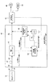
図3は、電力供給装置40の詳細な構成を示すブロック図である。
FIG. 3 is a block diagram illustrating a detailed configuration of the
電力供給装置40は、PWMコンバータ41、バッテリ42、及び充放電装置48と共に、充放電制御装置53を備える。
The
充放電装置48は、充放電制御装置53から出力される充放電電力指令値PTに基づいて、バッテリ42の充放電を制御すると共に、バッテリ42の充放電電力フィードバック値PBを充放電制御装置53へ出力する。
The charging / discharging
充放電制御装置53は、電力負荷が消費する電力と商用電源から供給される電力との電力差を算出する。
例えば、充放電制御装置53には、PWMコンバータ41から入力電力を示す値(入力電力フィードバック値PI)が入力され、各負荷駆動インバータ43から電力負荷で消費される電力を示す値(負荷消費電力フィードバック値PL)が入力される。なお、負荷消費電力PLは、負荷駆動インバータ43からの電圧V及び電流Iの積の総和(kW)から算出され、外乱要素である負荷変動を示している。
The charge /
For example, the charge and
なお、入力電力目標値PItargetは、予め定められた値、すなわち固定値とされる。 The input power target value P Itarget is a predetermined value, that is, a fixed value.
図4は、電力負荷で消費される電力の時間変化を示すグラフである。
図4は、横軸が時間変化、縦軸が電力とされており、電力負荷で消費される消費電力の時間変化を示している、なお、電力が正の場合は、電力負荷が電力を消費している場合である一方、電力が負の場合は、クレーン1が吊荷の巻き下げを行っている場合であり、巻き上げ用モータ49Gが電力を発生させている場合である。
FIG. 4 is a graph showing a time change of power consumed by the power load.
In FIG. 4, the horizontal axis represents time change and the vertical axis represents power, and shows the time change of power consumption consumed by the power load. When the power is positive, the power load consumes power. On the other hand, when the power is negative, the
そして、直線Aが消費電力の平均値を示しており、本第1実施形態では、一例として、入力電力目標値PItargetを上記平均値(例えば45kW)とする。 A straight line A indicates an average value of power consumption. In the first embodiment, as an example, the input power target value P Itarget is set to the average value (for example, 45 kW).
そして、(1)式に示すように、入力電力目標値PItargetと充放電電力指令値PTとの和が負荷消費電力PLとなる。そのため、(2)式に示すように、充放電電力指令値PTが、電力負荷が消費する電力と商用電源から供給される電力との電力差を示す値として、充放電制御装置53によって算出される。
PItarget+PT=PL ・・・(1)
PT=PL−PItarget ・・・(2)
As shown in the equation (1), the sum of the input power target value P Itarget and the charge / discharge power command value P T is the load power consumption P L. Therefore, as shown in the equation (2), the charge / discharge power command value P T is calculated by the charge /
P Itarget + P T = P L (1)
P T = P L −P Itarget (2)
(2)式に基づいて算出された充放電電力指令値PTは、充放電装置48へ出力される。
充放電装置48は、充放電電力指令値PTに応じた電力をバッテリ42から充放電させる。
具体的には、充放電装置48は、充放電電力指令値PTが正の場合、バッテリ42を放電させる一方、充放電電力指令値PTが負の場合、バッテリ42を充電させる充放電制御を行う。
The charge / discharge power command value P T calculated based on the equation (2) is output to the charge /
Charging / discharging
Specifically, the charge and
このように、充放電制御装置53から充放電装置48へ出力される充放電電力指令値PTは、各負荷駆動インバータ43から出力される負荷消費電力PLに基づいており、バッテリ42の充放電はフィードバック制御されている。このため、制御遅れが発生する場合は、遅れの影響を下記(3),(4)式に基づいて補償する。
Thus, charge and discharge power command value P T output from the charge-
ΔPT=K×(PItarget−PI) ・・・(3)
(3)式のKは制御ゲインであり予め定められており、PIはPWMコンバータ41から実際に出力される電力の値である。
PT=PT+ΔPT ・・・(4)
ΔP T = K × (P Itarget −P I ) (3)
In Equation (3), K is a control gain, which is determined in advance, and P I is a value of power actually output from the
P T = P T + ΔP T (4)
また、本第1実施形態のクレーン1は、現在のレーンRから他のレーンRへ移動可能とされており、電力供給装置40は、クレーン1がレーンR間を移動する場合、商用電源から供給される電力はないものとしてバッテリ42を充放電させる。
すなわち、クレーン1を他のレーンRへ移動させるために商用電源から電力を供給されない状態となっても、クレーン1を他のレーンRへ移動させることができる。
In addition, the
That is, the
より具体的には、充放電制御装置53が、給電コネクタ46の着脱信号に基づいて、給電ボックス31から給電されない状態を検知すると、入力電力目標値PItargetを0(零)とし、(2)式に基づいて、充放電電力指令値PTを算出し、商用電源からの無給電状態の電力負荷に対する電力充放電制御を行う。
なお、バッテリ42は、クレーン1のレーンR間の移動によって消費される電力を賄える電力容量を有するものが予め選択される。
More specifically, when the charge /
A
以上説明したように、本第1実施形態に係る電力供給装置40は、充放電可能であり、クレーン1の電力負荷に電力を供給するためのバッテリ42と、商用電源から予め定められた電力の供給を受けるPWMコンバータ41と、を備える。充放電制御装置53が、電力負荷が消費する電力と商用電源から供給される電力との電力差を算出し、充放電装置48が、算出された電力差に応じた電力をバッテリ42から充放電させる。
従って、本第1実施形態に係る電力供給装置40は、商用電源から供給される予め定められた電力(入力電力目標値PItarget)を低くしても(例えば45kW)、蓄電池から放電される電力が商用電源から供給される電力を補うこととなる。このため、本第1実施形態に係る電力供給装置40は、商用電源からクレーン1へ供給する電力を低電力とし低圧送電を可能にすることができる。
As described above, the
Therefore, the
また、商用電源からクレーン1の電力負荷に供給する電力を低電力にすることによって、クレーン1への給電ケーブル33のサイズを小さくすることができ、ケーブルリール47を小型化することができる。
Further, by reducing the power supplied from the commercial power source to the power load of the
〔第2実施形態〕
以下、本発明の第2実施形態について説明する。
[Second Embodiment]
Hereinafter, a second embodiment of the present invention will be described.
なお、本第2実施形態に係るクレーン1及び電力供給装置40の構成は、図1〜3に示す第1実施形態に係るクレーン1及び電力供給装置40の構成と同様であるので説明を省略する。
The configurations of the
本第2実施形態に係る電力供給装置40は、商用電源から供給される電力、すなわち入力電力目標値PItargetを、予め定められた電力以下で可変とする。
The
例えば、電力供給装置40は、バッテリ42の充電状態の履歴に基づいて、商用電源から供給される電力(入力電力目標値PItarget)を変化させる。
For example, the
バッテリ42が満充電に達すると、充電ができない状態となる。そのため、充放電制御装置53は、上記(2)式に基づくバッテリ42の充放電制御において、バッテリ42が満充電となると充放電電力指令値PTが負の場合でもバッテリ42の充電を一時停止させる。
When the
このような場合、充放電制御装置43は、充電すべき状態にあるにも関わらずバッテリ42が満充電のために充電を停止させる発生率p(商用電源から電力を供給された総時間に対する充電の停止時間の割合)をリアルタイムに算出し、入力電力目標値PItargetを算出する。
In such a case, the charge /
入力電力目標値PItargetは、例えば(5)式で算出される。
PItarget=k×(1−p)×PItarget・Base ・・・(5)
なお、kは予め定められた係数であり、PItarget・Baseは基準となる入力電力目標値(例えば45kW)である。
これにより、発生率pが大きい場合は、入力電力目標値PItargetが小さく変化する。
The input power target value P Itarget is calculated by, for example, equation (5).
P Itarget = k × (1-p) × P Itarget · Base (5)
Note that k is a predetermined coefficient, and P Itarget · Base is a reference input power target value (for example, 45 kW).
Thereby, when the occurrence rate p is large, the input power target value P Itarget changes small.
また、電力供給装置40は、バッテリ42の充電状態の履歴に基づいて、商用電源から供給される電力を変化させる他の例として、バッテリ42の充電率(SOC:State of Charge)の傾きαをリアルタイムに算出し、(6)式から入力電力目標値PItargetを算出する。
傾きαは、例えば、横軸を時間、縦軸を充電率としたグラフから充電率の時間変化の移動平均を算出し、該移動平均の傾きから求められる。
As another example of changing the power supplied from the commercial power source based on the charge state history of the
For example, the slope α is obtained from the slope of the moving average obtained by calculating the moving average of the time change of the charging rate from a graph in which the horizontal axis represents time and the vertical axis represents the charging rate.
そして、入力電力目標値PItargetは、例えば(6)式で算出される。
PItarget=k×(1−α)×PItarget・Base ・・・(6)
これにより、傾きが正、すなわちバッテリ42が充電されている割り合いが大きい場合は、入力電力目標値PItargetが小さく変化する。
The input power target value P Itarget is calculated by, for example, equation (6).
P Itarget = k × (1−α) × P Itarget · Base (6)
As a result, when the inclination is positive, that is, when the rate at which the
さらに、他の例として、電力供給装置40が、電力負荷へ供給する電力の履歴に基づいて、商用電源から供給される電力を変化させてもよい。
この例では、電力負荷で消費される電力の平均値(現在から所定時間前までの平均値)PItarget・averageを算出し、(7)式に示すように、入力電力目標値PItargetを平均値PItarget・averageとする。
PItarget=PItarget・average ・・・(7)
Furthermore, as another example, the
In this example, an average value of power consumed by the power load (average value from the present to a predetermined time before) P Itarget · average is calculated, and the input power target value P Itarget is averaged as shown in the equation (7). The value P Itarget · average .
P Itarget = P Itarget · average (7)
なお、商用電源から供給される電力の可変制御は、例えば、充放電制御装置53が上記(5)〜(7)式の何れか式を用いて、入力電力目標値PItargetを算出することで、その結果に応じて算出される充放電電力指令値PTを充放電装置48へ出力し、充放電電力指令値PTに基づいた電力をバッテリ42から充放電させる。
For example, the charge /
また、電力供給装置40は、発生率pや充電率の傾きαに応じて異なる入力電力目標値PItargetを予め記憶し、発生率pや充電率の傾きαに応じて入力電力目標値PItargetを変更してもよい。なお、入力電力目標値PItargetは、0(零)であってもよいし、負の値としてもよい。入力電力目標値PItargetが負の場合とは、クレーン1が吊荷を巻き下げる場合であって、モータ49が発電機として機能することによって発電し、該発電した電力を商用電源へ回生させる。
Further, the
以上説明したように、本第2実施形態に係る電力供給装置40は、バッテリ42の充電状態の履歴に基づいて、商用電源から供給される電力を変化させるので、バッテリ42の充電量が高い場合に、商用電源から供給される電力をより低くすることができる。
また、電力供給装置40は、電力負荷へ供給する電力の履歴に基づいて、商用電源から供給される電力を変化させるので、電力負荷で消費される電力が少ない場合に、商用電源から供給される電力をより低くすることができる。
また、本第2実施形態に係る電力供給装置40は、商用電源からの電力の供給を低くするため、抵抗器51によって消費される電力を削減することができ、抵抗器51を備える必要性を低下させることができる。
As described above, since the
Further, since the
In addition, the
〔第3実施形態〕
以下、本発明の第3実施形態について説明する。
[Third Embodiment]
Hereinafter, a third embodiment of the present invention will be described.
なお、本第3実施形態に係るクレーン1及び電力供給装置40の構成は、図1〜3に示す第1実施形態に係るクレーン1及び電力供給装置40の構成と同様であるので説明を省略する。
The configurations of the
電力供給装置40に備えられているバッテリ42の電力容量は、電力負荷のピーク電力を賄えなければならない。すなわち、より電力容量の小さなバッテリ42を用いるためには、電力負荷のピーク電力を低減させることが効果的である。
The power capacity of the
そこで、本第3実施形態では、クレーン1が吊荷を巻き上げる巻き動作時に電力負荷で消費される電力ピークを低減させる。
Therefore, in the third embodiment, the power peak consumed by the power load during the winding operation in which the
以下、本第3実施形態に係るクレーン1の巻き動作について具体的に説明する。
Hereinafter, the winding operation of the
まず、電力負荷へ供給する電力の制限値(供給電力制限値PLlimit)を設定し、供給電力制限値PLlimitに基づいて、巻き動作を制限する。 First, a limit value (supply power limit value P Llimit ) for power supplied to the power load is set, and the winding operation is limited based on the supply power limit value P Llimit .
ここで、電力負荷への供給電力制限値PLlimitと負荷消費電力PLとの関係は、下記(8)式が成立しなければならない。
PL<PLlimit ・・・(8)
Here, regarding the relationship between the supply power limit value P Llimit to the power load and the load power consumption P L , the following equation (8) must be established.
P L <P Llimit (8)
そして、負荷消費電力PLは下記(9)式及び(10)式のように細分化される。
PL=PMH+PAUX ・・・(9)
PMH=(9.8×M×V+a×(M+J)×V) ・・・(10)
(9)式において、PMHは巻き動作に必要な電力(巻き動作必要電力(kW))であり、PAUXは補機50で消費される電力の基準値(ベース電力(kW))である。
(10)式において、Mは吊荷質量(kg)、Vは巻き速度(m/s)、aは巻き加速度(m/s2)、Jは巻き上げドラムの慣性モーメントを質量相当に変換した値(kg)である。
Then, the load power consumption P L is subdivided as shown in the following equations (9) and (10).
P L = P MH + P AUX (9)
P MH = (9.8 × M × V + a × (M + J) × V) (10)
In Equation (9), P MH is power required for the winding operation (winding operation required power (kW)), and P AUX is a reference value (base power (kW)) of power consumed by the
In Equation (10), M is the mass of suspended load (kg), V is the winding speed (m / s), a is the winding acceleration (m / s 2 ), and J is the value obtained by converting the inertial moment of the winding drum into a mass equivalent. (Kg).
そして、(10)式に基づいて、供給電力制限値PLlimitの範囲内で出力できる最大の巻き速度Vや加速度aを算定する。 Then, based on the equation (10), the maximum winding speed V and acceleration a that can be output within the range of the supply power limit value P Llimit are calculated.
本第3実施形態に係るクレーン1は、吊荷を巻き上げる巻き動作における加速度aを変化させることで、電力負荷で消費される電力を抑制する巻き動作を行い、バッテリ42の電力容量を巻き動作によって抑制された電力に基づくものとする。
The
本第3実施形態に係る巻き動作について、図5を参照して説明する。
図5(a)は、従来の巻き動作の速度(巻き速度)の時間変化を示し、図5(b)は、図5(a)に対応する従来の巻き動作で消費される電力の時間変化を示している。
The winding operation according to the third embodiment will be described with reference to FIG.
FIG. 5A shows the time change of the speed (winding speed) of the conventional winding operation, and FIG. 5B shows the time change of the power consumed by the conventional winding operation corresponding to FIG. Is shown.
図5(b)に示すように、巻き速度を上昇させ、一定にする場合に電力ピークが現れる。
そこで、本第3実施形態では、図5(b)のように、クレーン1の巻き動作の加速度に応じて消費電力が過大となる場合に、巻き動作の加速度を変化させる。
As shown in FIG. 5B, a power peak appears when the winding speed is increased and made constant.
Therefore, in the third embodiment, as shown in FIG. 5B, when the power consumption is excessive according to the acceleration of the
図5(c)は、本第3実施形態に係る巻き動作の速度(巻き速度)の時間変化を示し、図5(d)は、図5(c)に対応する本第3実施形態に係る巻き動作で消費される電力の時間変化を示している。
本第3実施形態に係る巻き動作では、図5(d)に示すように、消費電力が予め設定された供給電力制限値PLlimit以下となるように、図5(c)に示すように、巻き速度を一定にする前における巻き動作の加速度を変化させる。
FIG.5 (c) shows the time change of the speed | rate (winding speed) of the winding operation | movement which concerns on this 3rd Embodiment, FIG.5 (d) concerns on this 3rd Embodiment corresponding to FIG.5 (c). The time change of the electric power consumed by winding operation is shown.
In the winding operation according to the third embodiment, as shown in FIG. 5 (d), as shown in FIG. 5 (d), as shown in FIG. 5 (c), the power consumption is equal to or less than a preset supply power limit value P Llimit . The acceleration of the winding operation before the winding speed is made constant is changed.
なお、加速度が低下するように変化させることによって、巻き動作に要する総時間が、加速度を変化させない場合に比べて長くなる。そのため、一定とする巻き速度を、加速度を変化させない場合に比較して速くすることによって、巻き動作に要する総時間が長くなることを防止してもよい。 Note that by changing the acceleration so as to decrease, the total time required for the winding operation becomes longer than when the acceleration is not changed. Therefore, the total time required for the winding operation may be prevented from becoming longer by increasing the constant winding speed as compared with the case where the acceleration is not changed.
このように、本第3実施形態では、クレーン1の巻き動作における過大な消費電力の発生を抑制させるので、バッテリ42の電力容量を、巻き動作によって抑制された電力に基づいて決定することができ、より電力容量が低いバッテリ42を用いることができる。
Thus, in this 3rd Embodiment, since generation | occurrence | production of the excessive power consumption in the winding operation | movement of the
〔第4実施形態〕
以下、本発明の第4実施形態について説明する。
図6は、本第4実施形態に係るクレーン1の電気的構成及び電力供給装置40の電気的構成を示す。なお、図6における図3と同一の構成部分については図3と同一の符号を付して、その説明を省略する。
[Fourth Embodiment]
The fourth embodiment of the present invention will be described below.
FIG. 6 shows an electrical configuration of the
本第4実施形態に係るクレーン1’は、エンジン60の駆動によって発電する発電機61(エンジン発電機66)を備えた従来のRTGにおいて、既存の発電機61を廃し、これに代わる電力供給装置40’を設置した形態を示したものである。従来のRTGでは、発電機61から出力される交流電力は、負荷駆動インバータ62を介してモータ49及び補機50に供給されており、本第4実施形態に係るクレーン1’では、既存の発電機61に代わる電力供給装置40’の出力を交流電力とすることで、従来のRTGを改造する場合に好適な形態となっている。
The
本第4実施形態に係る電力供給装置40’は、バッテリ42、PWMコンバータ41、並びにクレーン1’の電力負荷への給電路63へバッテリ42及びPWMコンバータ41からの電力を供給するための直流電力を交流電力に変換し供給するDC/ACインバータ65を備え、電力供給装置40’から供給される電力によってクレーン1’の電力負荷を駆動可能としている。また、本第4実施形態に係る電力供給装置40’は、DC/ACインバータ65から充放電制御装置53へ負荷消費電力PLが出力される。
The
すなわち、本第4実施形態に係る電力供給装置40’は、発電機61によって電力負荷へ電力を供給していた既存のクレーン1’の電力負荷への給電路へ、接続されることによって、該既存のクレーン1’の電力負荷を、バッテリ42と商用電源から供給される電力によって駆動させることができる。
そして、本第4実施形態に係る電力供給装置40’は、商用電源から供給される予め定められた電力を低くしても(例えば45kW)、バッテリ42から放電される電力が商用電源から供給される電力を補うこととなるので、商用電源からクレーンへ供給する電力を低電力にすることができる。
That is, the
And even if electric power supply apparatus 40 'which concerns on this 4th Embodiment makes low predetermined electric power supplied from commercial power supply (for example, 45 kW), the electric power discharged from the
なお、本第4実施形態では、既存の発電機61をクレーン1’から廃する形態について説明したが、必ずしも既存の発電機61をクレーン1’から廃する必要はなく、既存の発電機61をクレーン1’に備えたままで、電力供給装置40’をクレーン1’に接続してもよい。この場合、クレーン1’は、発電機61と電力供給装置40’を併用して電力負荷へ電力を供給してもよい。
In addition, although the form which discards the existing
以上、本発明を、上記各実施形態を用いて説明したが、本発明の技術的範囲は上記実施形態に記載の範囲には限定されない。発明の要旨を逸脱しない範囲で上記各実施形態に多様な変更または改良を加えることができ、該変更または改良を加えた形態も本発明の技術的範囲に含まれる。 As mentioned above, although this invention was demonstrated using said each embodiment, the technical scope of this invention is not limited to the range as described in the said embodiment. Various changes or improvements can be added to the above-described embodiments without departing from the gist of the invention, and embodiments to which the changes or improvements are added are also included in the technical scope of the present invention.
1 クレーン
1’ クレーン
40 電力供給装置
40’ 電力供給装置
41 PWMコンバータ
42 バッテリ
48 充放電装置
49 モータ
50 補機
53 充放電制御装置
65 DC/ACインバータ
DESCRIPTION OF
Claims (9)
商用電源から予め定められた電力の供給を受ける受電手段と、
前記クレーンの電力負荷が消費する電力と前記商用電源から供給される電力との電力差を算出する算出手段と、
前記算出手段によって算出された電力差に応じた電力を前記蓄電池から充放電させる制御手段と、
を備え、
前記クレーンは、吊荷を巻き上げる巻き動作における加速度を変化させることで、前記クレーンの電力負荷で消費される電力を抑制する巻き動作を行い、
前記蓄電池の電力容量は、前記巻き動作によって抑制された電力に基づく電力供給装置。 A storage battery that is chargeable / dischargeable and provided to the crane to supply power to the crane's power load;
Power receiving means for receiving a predetermined power supply from a commercial power source;
Calculating means for calculating a power difference between the power consumed by the crane's power load and the power supplied from the commercial power supply;
Control means for charging and discharging power from the storage battery according to the power difference calculated by the calculating means;
Equipped with a,
The crane performs a winding operation that suppresses the power consumed by the power load of the crane by changing the acceleration in the winding operation of winding the suspended load,
The power capacity of the storage battery is a power supply device based on the power suppressed by the winding operation .
充放電可能であり、前記クレーンの電力負荷に電力を供給するために前記クレーンに備えられる蓄電池と、
商用電源から予め定められた電力の供給を受ける受電手段と、
前記クレーンの電力負荷が消費する電力と前記商用電源から供給される電力との電力差を算出する算出手段と、
前記算出手段によって算出された電力差に応じた電力を前記蓄電池から充放電させる制御手段と、
前記クレーンの電力負荷への給電路へ前記蓄電池及び前記受電手段からの直流電力を交流電力に変換し供給する供給手段と、
を備え、
前記クレーンは、吊荷を巻き上げる巻き動作における加速度を変化させることで、前記クレーンの電力負荷で消費される電力を抑制する巻き動作を行い、
前記蓄電池の電力容量は、前記巻き動作によって抑制された電力に基づく電力供給装置。 A power supply device that supplies AC power to a power load of a crane equipped with a generator or a crane that has abandoned an existing generator,
A storage battery that is chargeable / dischargeable and provided to the crane to supply power to the crane's power load;
Power receiving means for receiving a predetermined power supply from a commercial power source;
Calculating means for calculating a power difference between the power consumed by the crane's power load and the power supplied from the commercial power supply;
Control means for charging and discharging power from the storage battery according to the power difference calculated by the calculating means;
Supply means for converting and supplying DC power from the storage battery and the power receiving means to AC power to a power supply path to the power load of the crane;
Equipped with a,
The crane performs a winding operation that suppresses the power consumed by the power load of the crane by changing the acceleration in the winding operation of winding the suspended load,
The power capacity of the storage battery is a power supply device based on the power suppressed by the winding operation .
前記制御手段は、前記クレーンがレーン間を移動する場合、前記商用電源から供給される電力はないものとして前記蓄電池を充放電させる請求項1又は請求項2記載の電力供給装置。 The crane is movable to another lane,
3. The power supply device according to claim 1, wherein when the crane moves between lanes, the control unit charges and discharges the storage battery on the assumption that no electric power is supplied from the commercial power source.
前記電力供給装置から供給される電力によって駆動する電力負荷と、
を備えたクレーン。 The power supply device according to any one of claims 1 to 6 ,
A power load driven by power supplied from the power supply device;
Crane with.
前記クレーンの電力負荷が消費する電力と前記商用電源から供給される電力との電力差を算出する第1工程と、
前記第1工程によって算出された電力差に応じた電力を前記蓄電池から充放電させる第2工程と、
を含み、
前記クレーンは、吊荷を巻き上げる巻き動作における加速度を変化させることで、前記クレーンの電力負荷で消費される電力を抑制する巻き動作を行い、
前記蓄電池の電力容量は、前記巻き動作によって抑制された電力に基づく電力供給方法。 A storage battery that is chargeable / dischargeable and that is provided in the crane for supplying power to the power load of the crane, and a power receiving means that receives supply of predetermined power from a commercial power source. A power supply method for supplying power,
A first step of calculating a power difference between power consumed by the power load of the crane and power supplied from the commercial power source;
A second step of charging and discharging power from the storage battery according to the power difference calculated in the first step;
Only including,
The crane performs a winding operation that suppresses the power consumed by the power load of the crane by changing the acceleration in the winding operation of winding the suspended load,
The power capacity of the storage battery is a power supply method based on the power suppressed by the winding operation .
前記クレーンの電力負荷が消費する電力と前記商用電源から供給される電力との電力差を算出する第1工程と、
前記第1工程によって算出された電力差に応じた電力を前記蓄電池から充放電させる第2工程と、
を含み、
前記クレーンは、吊荷を巻き上げる巻き動作における加速度を変化させることで、前記クレーンの電力負荷で消費される電力を抑制する巻き動作を行い、
前記蓄電池の電力容量は、前記巻き動作によって抑制された電力に基づく電力供給方法。 A storage battery that is chargeable / dischargeable and is provided in the crane for supplying power to the power load of the crane, power receiving means for receiving a predetermined power supply from a commercial power source, and a power supply path to the power load of the crane And supply means for converting the DC power from the storage battery and the power receiving means into AC power and supplying the AC power to the power load of the crane equipped with the generator or the crane without the existing generator A power supply method for a power supply device to
A first step of calculating a power difference between power consumed by the power load of the crane and power supplied from the commercial power source;
A second step of charging and discharging power from the storage battery according to the power difference calculated in the first step;
Only including,
The crane performs a winding operation that suppresses the power consumed by the power load of the crane by changing the acceleration in the winding operation of winding the suspended load,
The power capacity of the storage battery is a power supply method based on the power suppressed by the winding operation .
Priority Applications (8)
| Application Number | Priority Date | Filing Date | Title |
|---|---|---|---|
| JP2011009245A JP5725877B2 (en) | 2011-01-19 | 2011-01-19 | Power supply apparatus, crane, and power supply method. |
| IN1259DEN2012 IN2012DN01259A (en) | 2011-01-19 | 2011-04-25 | |
| KR1020127003989A KR20120112364A (en) | 2011-01-19 | 2011-04-25 | Power supply apparatus, crane, and power supply method |
| CN201180003464.2A CN102714424B (en) | 2011-01-19 | 2011-04-25 | Power-supply device, crane, and power-supply method |
| PCT/JP2011/060091 WO2012098699A1 (en) | 2011-01-19 | 2011-04-25 | Power-supply device, crane, and power-supply method |
| KR1020137034232A KR101589360B1 (en) | 2011-01-19 | 2011-04-25 | Power supply apparatus, crane, and power supply method |
| SG2012009361A SG182246A1 (en) | 2011-01-19 | 2011-04-25 | Power-supply apparatus, crane, and power supply method |
| HK12112237.4A HK1171579A1 (en) | 2011-01-19 | 2012-11-28 | Power-supply device, crane, and power-supply method |
Applications Claiming Priority (1)
| Application Number | Priority Date | Filing Date | Title |
|---|---|---|---|
| JP2011009245A JP5725877B2 (en) | 2011-01-19 | 2011-01-19 | Power supply apparatus, crane, and power supply method. |
Publications (2)
| Publication Number | Publication Date |
|---|---|
| JP2012152039A JP2012152039A (en) | 2012-08-09 |
| JP5725877B2 true JP5725877B2 (en) | 2015-05-27 |
Family
ID=46515347
Family Applications (1)
| Application Number | Title | Priority Date | Filing Date |
|---|---|---|---|
| JP2011009245A Active JP5725877B2 (en) | 2011-01-19 | 2011-01-19 | Power supply apparatus, crane, and power supply method. |
Country Status (7)
| Country | Link |
|---|---|
| JP (1) | JP5725877B2 (en) |
| KR (2) | KR20120112364A (en) |
| CN (1) | CN102714424B (en) |
| HK (1) | HK1171579A1 (en) |
| IN (1) | IN2012DN01259A (en) |
| SG (1) | SG182246A1 (en) |
| WO (1) | WO2012098699A1 (en) |
Families Citing this family (9)
| Publication number | Priority date | Publication date | Assignee | Title |
|---|---|---|---|---|
| JP5935301B2 (en) * | 2011-11-17 | 2016-06-15 | 住友重機械搬送システム株式会社 | Power supply apparatus and supply power control method |
| JP6048527B2 (en) * | 2015-03-27 | 2016-12-21 | 日本電気株式会社 | Control device |
| JP5943114B1 (en) | 2015-03-27 | 2016-06-29 | 日本電気株式会社 | Control device |
| US10095298B2 (en) | 2015-03-27 | 2018-10-09 | Nec Corporation | Control device |
| CN104966855B (en) * | 2015-06-26 | 2017-09-15 | 北京百度网讯科技有限公司 | Electric discharge device and charging method for battery |
| CN106608594A (en) * | 2015-10-27 | 2017-05-03 | 广东保达动力技术有限公司 | Extended-range energy-saving hybrid power system applied to cranes |
| TWI612007B (en) * | 2016-06-06 | 2018-01-21 | 台灣積體電路製造股份有限公司 | Overhead hoist transporter and associated vehicle and control method |
| JP7221634B2 (en) * | 2018-10-02 | 2023-02-14 | 株式会社大林組 | Power receiving equipment |
| FR3120618B1 (en) * | 2021-03-10 | 2023-11-03 | Manitowoc Crane Group France | Method for managing the electrical power of a crane from a primary source and a rechargeable secondary source |
Family Cites Families (6)
| Publication number | Priority date | Publication date | Assignee | Title |
|---|---|---|---|---|
| JP2003299250A (en) * | 2002-03-29 | 2003-10-17 | Hitachi Ltd | Power supply unit and elevator apparatus |
| JP2006238516A (en) * | 2005-02-22 | 2006-09-07 | Ishikawajima Harima Heavy Ind Co Ltd | Load driving unit |
| JP4856421B2 (en) | 2005-12-13 | 2012-01-18 | 株式会社小川製作所 | Control system and control method for electrically driven construction tower crane |
| JP5082450B2 (en) * | 2007-01-12 | 2012-11-28 | 株式会社明電舎 | Power supply equipment |
| JP2010149954A (en) * | 2008-12-24 | 2010-07-08 | Mitsubishi Heavy Ind Ltd | Power supply switching device of tire type crane and tire type crane system |
| CN101521470B (en) * | 2009-03-26 | 2012-10-03 | 严兆基 | Power supply method and power supply system for rubber-tyred container gantry crane |
-
2011
- 2011-01-19 JP JP2011009245A patent/JP5725877B2/en active Active
- 2011-04-25 IN IN1259DEN2012 patent/IN2012DN01259A/en unknown
- 2011-04-25 KR KR1020127003989A patent/KR20120112364A/en active Application Filing
- 2011-04-25 WO PCT/JP2011/060091 patent/WO2012098699A1/en active Application Filing
- 2011-04-25 KR KR1020137034232A patent/KR101589360B1/en active IP Right Grant
- 2011-04-25 CN CN201180003464.2A patent/CN102714424B/en active Active
- 2011-04-25 SG SG2012009361A patent/SG182246A1/en unknown
-
2012
- 2012-11-28 HK HK12112237.4A patent/HK1171579A1/en unknown
Also Published As
| Publication number | Publication date |
|---|---|
| CN102714424B (en) | 2015-07-15 |
| IN2012DN01259A (en) | 2015-05-15 |
| CN102714424A (en) | 2012-10-03 |
| KR101589360B1 (en) | 2016-01-29 |
| KR20120112364A (en) | 2012-10-11 |
| WO2012098699A1 (en) | 2012-07-26 |
| JP2012152039A (en) | 2012-08-09 |
| KR20140015576A (en) | 2014-02-06 |
| SG182246A1 (en) | 2012-08-30 |
| HK1171579A1 (en) | 2013-03-28 |
Similar Documents
| Publication | Publication Date | Title |
|---|---|---|
| JP5725877B2 (en) | Power supply apparatus, crane, and power supply method. | |
| JP5414397B2 (en) | Feeding type cargo handling equipment | |
| WO2009123041A1 (en) | Crane system | |
| JP5800159B2 (en) | Crane apparatus and control method thereof | |
| JP2011162287A (en) | Power feeding device and tire type gantry crane including the same | |
| JP2007267504A (en) | Storage apparatus of crane, crane power supply and power supply facility of crane | |
| JP2011068499A (en) | Crane device | |
| JP2009023816A (en) | Crane device | |
| JP2011136838A (en) | Hoisting machine | |
| JP5751764B2 (en) | Crane control device and crane device | |
| JP5039525B2 (en) | Yard crane | |
| JP6189010B2 (en) | Crane and power supply method for crane | |
| JP5935300B2 (en) | Power supply apparatus and charge / discharge control method | |
| JP6196764B2 (en) | Power supply apparatus, power supply method and program | |
| JP5622211B2 (en) | Hybrid cargo handling equipment | |
| JP2010089855A (en) | Crane device and control method of crane device | |
| JP5538696B2 (en) | Feeding type cargo handling equipment | |
| JP5622599B2 (en) | Crane feeding cable reel device and crane equipped with the same | |
| JP2010241602A (en) | Cargo handling device | |
| JP2011111278A (en) | Crane control device and crane device | |
| CN217398285U (en) | Port gantry crane energy storage feedback emergency control system | |
| JP5488572B2 (en) | Cargo handling system |
Legal Events
| Date | Code | Title | Description |
|---|---|---|---|
| A711 | Notification of change in applicant |
Free format text: JAPANESE INTERMEDIATE CODE: A712 Effective date: 20120824 |
|
| A625 | Written request for application examination (by other person) |
Free format text: JAPANESE INTERMEDIATE CODE: A625 Effective date: 20130522 |
|
| A131 | Notification of reasons for refusal |
Free format text: JAPANESE INTERMEDIATE CODE: A131 Effective date: 20140513 |
|
| A521 | Request for written amendment filed |
Free format text: JAPANESE INTERMEDIATE CODE: A523 Effective date: 20140711 |
|
| A131 | Notification of reasons for refusal |
Free format text: JAPANESE INTERMEDIATE CODE: A131 Effective date: 20140812 |
|
| A521 | Request for written amendment filed |
Free format text: JAPANESE INTERMEDIATE CODE: A523 Effective date: 20141014 |
|
| TRDD | Decision of grant or rejection written | ||
| A01 | Written decision to grant a patent or to grant a registration (utility model) |
Free format text: JAPANESE INTERMEDIATE CODE: A01 Effective date: 20150303 |
|
| A61 | First payment of annual fees (during grant procedure) |
Free format text: JAPANESE INTERMEDIATE CODE: A61 Effective date: 20150331 |
|
| R150 | Certificate of patent or registration of utility model |
Ref document number: 5725877 Country of ref document: JP Free format text: JAPANESE INTERMEDIATE CODE: R150 |
|
| S111 | Request for change of ownership or part of ownership |
Free format text: JAPANESE INTERMEDIATE CODE: R313111 |
|
| R350 | Written notification of registration of transfer |
Free format text: JAPANESE INTERMEDIATE CODE: R350 |
|
| S531 | Written request for registration of change of domicile |
Free format text: JAPANESE INTERMEDIATE CODE: R313531 |
|
| R350 | Written notification of registration of transfer |
Free format text: JAPANESE INTERMEDIATE CODE: R350 |
|
| R250 | Receipt of annual fees |
Free format text: JAPANESE INTERMEDIATE CODE: R250 |