JP2011136838A - Hoisting machine - Google Patents
Hoisting machine Download PDFInfo
- Publication number
- JP2011136838A JP2011136838A JP2010000241A JP2010000241A JP2011136838A JP 2011136838 A JP2011136838 A JP 2011136838A JP 2010000241 A JP2010000241 A JP 2010000241A JP 2010000241 A JP2010000241 A JP 2010000241A JP 2011136838 A JP2011136838 A JP 2011136838A
- Authority
- JP
- Japan
- Prior art keywords
- motor
- hoisting
- regenerative
- switch
- power storage
- Prior art date
- Legal status (The legal status is an assumption and is not a legal conclusion. Google has not performed a legal analysis and makes no representation as to the accuracy of the status listed.)
- Abandoned
Links
Images
Landscapes
- Elevator Control (AREA)
- Control And Safety Of Cranes (AREA)
Abstract
【課題】巻き下げ動作で生じる回生エネルギーを巻き上げ動作に利用することにより、回生エネルギーおよび回生エネルギーを処理する回路等を有効利用することのできる巻上機を得る。
【解決手段】本発明に係る巻上機は、モータが巻き下げ動作を行なうときに生じる回生電力を蓄電する装置を備えている。
【選択図】図3A rewinding machine capable of effectively using regenerative energy and a circuit for processing the regenerative energy is obtained by using regenerative energy generated in the lowering operation for the hoisting operation.
A hoisting machine according to the present invention includes a device that stores regenerative power generated when a motor performs a lowering operation.
[Selection] Figure 3
Description
本発明は、巻上機に関するものである。 The present invention relates to a hoisting machine.
巻上機は、重い荷物をモータによって上方に巻き上げる装置である。巻上機の動作は、巻き上げ以外にも、荷物を上方から下方へ巻き下げる動作がある。このとき、鉛直下方向(巻き下げ方向)にL(m)移動する質量m(kg)の荷物は、重力加速度をg(m/s2)とすると、m×g×L(J)の重力による位置エネルギーを失う。このエネルギーは、モータから生じる回生エネルギーとなる。 The hoisting machine is a device for hoisting a heavy load upward by a motor. In addition to hoisting, the hoisting machine has an operation of unwinding the load from above to below. At this time, a load of mass m (kg) that moves L (m) vertically downward (winding direction) has a gravity of m × g × L (J), where g (m / s 2 ) is the gravitational acceleration. Lose potential energy. This energy becomes regenerative energy generated from the motor.
例えば、モータを制御するためインバータを用いている場合、この回生エネルギーが素子の過電流などを引き起こし、故障の原因となる。そのため、回生エネルギーを処理する仕組みが必要である。 For example, when an inverter is used to control a motor, this regenerative energy causes an overcurrent of the element and causes a failure. Therefore, a mechanism for processing regenerative energy is necessary.
従来のインバータを用いた巻上機では、回生エネルギーを抵抗器などに供給し、ジュール熱に変換して消費させる手法が用いられている。その他、下記特許文献1では、回生エネルギーをコンバータによって交流に変換し、電源側に交流帰還させている。 In a conventional hoisting machine using an inverter, a method is used in which regenerative energy is supplied to a resistor or the like, converted into Joule heat and consumed. In addition, in Patent Document 1 below, regenerative energy is converted into alternating current by a converter, and AC feedback is made to the power supply side.
従来のインバータを用いた巻上機では、巻き下げ動作で発生する回生エネルギーを消費するため、巻上機本来の動作とは関係のない抵抗器などの装置が必要となっていた。上記特許文献1においても同様に、本来の動作のために必要な回路構成とは別に、回生エネルギーを処理するためのコンバータが別途必要となる。 In a conventional hoisting machine using an inverter, regenerative energy generated by the lowering operation is consumed, and thus a device such as a resistor that is not related to the original operation of the hoisting machine is required. Similarly in Patent Document 1, a converter for processing regenerative energy is required separately from the circuit configuration necessary for the original operation.
このような、本来の動作のために必要な回路構成とは別に回生エネルギーを処理するための装置等を有する構成は、巻上機の構成上非効率であるのみならず、回生エネルギーを有効利用できていない点で、巻上機の省エネルギー化の観点から課題がある。 Such a configuration having a device for processing regenerative energy separately from the circuit configuration necessary for the original operation is not only inefficient in the configuration of the hoist, but also effectively uses the regenerative energy. There is a problem from the viewpoint of energy saving of the hoisting machine because it is not made.
本発明は、上記のような課題を解決するためになされたものであり、巻き下げ動作で生じる回生エネルギーを巻き上げ動作に利用することにより、回生エネルギーおよび回生エネルギーを処理する回路等を有効利用することのできる巻上機を得ることを目的とする。 The present invention has been made to solve the above-described problems, and effectively uses a regenerative energy and a circuit for processing the regenerative energy by using the regenerative energy generated by the lowering operation for the hoisting operation. The purpose is to obtain a hoisting machine that can handle.
本発明に係る巻上機は、モータが巻き下げ動作を行なうときに生じる回生電力を蓄電する装置を備えている。 The hoisting machine according to the present invention includes a device that stores regenerative power generated when the motor performs a lowering operation.
本発明に係る巻上機によれば、モータが巻き下げ動作を行なうときに生じる回生電力を貯めておき、巻上機本来の動作である巻き上げ動作を行なうときに貯めた電力を用いることができる。これにより、回生エネルギーおよびこれを処理するための回路等を有効利用して省エネルギー化を図ることができる。 According to the hoisting machine according to the present invention, the regenerative electric power generated when the motor performs the lowering operation can be stored, and the electric power stored when the hoisting operation which is the original operation of the hoisting machine can be used. . Thereby, it is possible to save energy by effectively using regenerative energy and a circuit for processing the regenerative energy.
<実施の形態1>
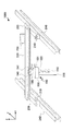
図1は、本発明の実施の形態1に係るクレーン装置1000の構成図である。クレーン装置100は、重い荷物を吊り上げて縦横に移動させる装置であり、巻上機100、走行用装置200、入力装置300を備える。
<Embodiment 1>
FIG. 1 is a configuration diagram of a
巻上機100は、荷物を図1のz軸方向に巻き上げ、巻き上げた荷物を図1のx軸方向に移動させる装置であり、クレーンフック110、ワイヤロープ120、巻上用装置130、横行用装置140、巻上横行インバータ装置150を備える。
The
クレーンフック110は、巻き上げる荷物を取り付ける部材である。クレーンフック110に荷物を取り付けてワイヤロープ120を巻上用装置130で巻き取ることにより、荷物を図1のz軸方向に巻き上げ、または巻き下げる。
The
巻上用装置130は、巻上用モータ131を用いてワイヤロープ120を巻き上げ、または巻き下げる装置である。横行用装置140は、横行用モータ141を用いて巻上機100を後述の横行用ガーダー220に沿って図1のx軸方向に移動させる装置である。
The hoisting
巻上横行インバータ装置150は、後述の図2で説明する巻上用インバータ151と横行用インバータ153を制御し、巻上用モータ131と横行用モータ141を駆動して上記動作を実行する。
The hoisting and
走行用装置200は、図1のy軸方向に巻上機100を移動させる装置であり、走行用モータ210、横行用ガーダー220、走行用インバータ装置230、走行用ガーダー240を備える。
The
走行用モータ210は、走行用装置200を走行用ガーダー240に沿って図1のy軸方向に移動させる。走行用インバータ装置230は、後述の図2で説明する走行用インバータ232を制御し、走行用モータ210を駆動して上記動作を実行する。
The traveling
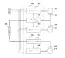
図2は、巻上横行インバータ装置150と走行用インバータ装置230の機能ブロック図である。以下、各装置の構成について説明する。
FIG. 2 is a functional block diagram of the winding
巻上横行インバータ装置150は、巻上用インバータ151、巻上・横行用インバータ制御部152、横行用インバータ153を備える。
The hoisting and
巻上用インバータ151は、巻上用モータ131に周波数可変の交流電圧を印加して巻上用モータ131を所望の運転速度で駆動する。横行用インバータ153は、同様に横行用モータ141に周波数可変の交流電圧を印加して横行用モータ141を所望の運転速度で駆動する。
The
巻上・横行用インバータ制御部152は、巻上用インバータ151と横行用インバータ153の動作を制御することにより、巻上用モータ131と横行用モータ141を駆動制御する。また、巻上・横行用インバータ制御部152は、モータブレーキ161を稼動させ、または解除する。これにより、クレーンフック110に取り付けられている荷物を自由落下させることなく、安全にz軸方向に移動させることができる。同様に、モータブレーキ162を稼動させ、または解除することにより、巻上機100を安全にx軸方向に移動させることができる。
The hoisting / traverse
巻上・横行用インバータ制御部152は、その機能を実現する回路デバイスのようなハードウェアを用いて構成することもできるし、マイコンやCPU(Central Processing Unit)のような演算装置とその動作を規定するソフトウェアを用いて構成することもできる。
The hoisting / traversing
走行用インバータ装置230は、走行インバータ制御部231、走行用インバータ232を備える。
The traveling
走行用インバータ232は、走行用モータ210に周波数可変の交流電圧を印加して走行用モータ210を駆動する。
The
走行インバータ制御部231は、走行用インバータ232の動作を制御することにより走行用モータ210を所望の運転速度で駆動する。また、モータブレーキ250を稼動させ、または解除することにより、走行用装置200を安全にy軸方向に移動させることができる。
The traveling
走行インバータ制御部231は、その機能を実現する回路デバイスのようなハードウェアを用いて構成することもできるし、マイコンやCPUのような演算装置とその動作を規定するソフトウェアを用いて構成することもできる。
The traveling
入力装置300は、巻上・横行用インバータ制御部152と走行インバータ制御部231に対して操作指令を出力する。巻上・横行用インバータ制御部152と走行インバータ制御部231は、この操作指令に基づき各インバータを制御し、これにより各モータを駆動制御して所望の動作を実行する。
The
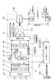
図3は、巻上用インバータ151の回路図である。巻上用インバータ151は、整流部31、整流コンデンサ32、駆動素子部33、回生駆動スイッチ34、回生抵抗35、蓄電部36、負荷判別部37、スイッチSWr38、スイッチSWc39、電圧モニタ部40を備える。
FIG. 3 is a circuit diagram of the
整流部31と整流コンデンサ32は、3相交流電力を直流に変換する。駆動素子部33は、スイッチング素子などを用いて直流を交流に変換し、所望の周波数の交流電力を出力するインバータとして構成されている。
The
巻上・横行インバータ制御部152は、入力装置300から受け取った操作指令に基づき、インバータ駆動制御信号を駆動素子部33に出力する。駆動素子部33は、インバータ駆動制御信号に基づき、巻上用モータ131を所望の速度と回転力で駆動させるための交流電圧を、巻上用モータ131に印加する。巻上用モータ131は、印加された交流電圧によって駆動し、ワイヤロープ120を巻上ドラム132によって巻き上げ、または巻き下げて、荷物を所望の速度で上下に移動させる。
The hoisting / traversing
蓄電部36は、例えばキャパシタなどを用いて構成され、巻上用モータ131が巻き下げ動作を行なうときに生じる回生エネルギーを電気エネルギーとして蓄電する機能を有する。巻上・横行インバータ制御部152は、スイッチSWc39をON/OFFすることにより、蓄電部36と駆動素子部33の間の接続を切り替える。回生エネルギーを蓄電するときはスイッチSWc39をONにし、蓄電しないときはOFFにする。また、蓄電部36が蓄電している電気エネルギーを放出するときは、スイッチSWc39をONにして蓄電部36を駆動素子部33に接続する。
The
蓄電部36の具体的な構成として、例えば大容量、高速充電、放電が可能な電気二重層キャパシタを用いることが考えられる。その他の蓄電機能を有するデバイス等を用いることもできる。ただし、蓄電容量、充放電するための時間などの仕様を、巻上機100が実際に持ち上げる荷物の重量、巻き下げ動作時に発生する回生エネルギーの量などに合わせて調整する必要がある。
As a specific configuration of the
回生抵抗35は、蓄電部36が回生エネルギーを蓄電しないとき、回生エネルギーを熱エネルギーとして消費させるための電気抵抗である。巻上・横行インバータ制御部152は、スイッチSWr38と回生駆動スイッチ34をON/OFFすることにより、回生抵抗35と駆動素子部33の間の接続を切り替える。回生エネルギーを消費させるときはスイッチSWr38と回生駆動スイッチ34をONにし、消費させないときは少なくともいずれか一方をOFFにする。スイッチSWr38と回生駆動スイッチ34は、いずれか一方を設けずに省略してもよい。
The
負荷判別部37は、クレーンフック110に取り付けられている荷物の重量を判別し、その判別結果を巻上・横行インバータ制御部152に出力する。荷物の重量を判別する手法には、任意の公知技術を用いることができる。また、負荷判別部37は例えば電流などの検出値のみを巻上・横行インバータ制御部152に出力し、実際に荷物の重量を算出する処理は巻上・横行インバータ制御部152が実行するようにしてもよい。
The
電圧モニタ部40は、直流母線間電圧Vpnを監視し、その測定値を巻上・横行インバータ制御部152に出力する。
The
本発明における「第1スイッチ」は、スイッチSWc39が相当する。「第2スイッチ」は、スイッチSWr38が相当する。「第3スイッチ」は、回生駆動スイッチ34が相当する。
The “first switch” in the present invention corresponds to the switch SWc39. The “second switch” corresponds to the switch SWr38. The “third switch” corresponds to the
以上、クレーン装置1000および巻上機100の構成を説明した。なお、図3では蓄電部36と回生抵抗35を双方備える構成を説明したが、蓄電部36の蓄電容量が必要とされる容量を満たし、充放電に要する時間が十分に短ければ、回生抵抗35、スイッチSWr38、回生駆動スイッチ34を設けなくともよい。
The configuration of the
以上のように、本実施の形態1に係る巻上機100は、巻上用モータ131が巻き下げ動作を行なうときに生じる回生エネルギーを蓄電する蓄電部36を備える。これにより、回生エネルギーを全て消費させることなく貯めておき、後に巻き上げ動作を行なうときなどのエネルギー源として貯めておいた電気エネルギーを用いることができる。すなわち、回生エネルギーを有効利用することができるので、巻上機100の省エネルギー化の観点から好ましい。
As described above, the hoisting
また、本実施の形態1において、巻上・横行インバータ制御部152は、スイッチSWc39をON/OFFすることにより、蓄電部36に回生エネルギーを蓄電させるか否かを切り替えることができる。これにより、蓄電部36の充電容量に合った最適な充電時間で回生エネルギーを蓄電することができる。
Further, in the first embodiment, the hoisting / traverse
<実施の形態2>
本発明の実施の形態2では、巻上機100の動作を、巻上用モータ131の巻き下げ動作によって生じる回生エネルギーの観点から詳細に検討する。また、蓄電部36が必要とする容量についても併せて検討する。なお、各機器の構成は実施の形態1と同様である。
<
In the second embodiment of the present invention, the operation of the hoisting
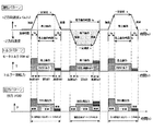
図4は、巻上用モータ131の動作過程を示すタイムチャートである。以下では、図4の各期間で生じる回生エネルギーおよび巻き上げ動作に必要となるエネルギーについて検討する。
FIG. 4 is a time chart showing an operation process of the hoisting
(1)巻き下げ動作によって生じる回生エネルギー
巻下方向に荷物(質量m)が移動すると、重力の位置エネルギーの減少分に相当する巻上用モータ131において回生エネルギーEkとして生じる。スイッチSWc39をONにすると、回生エネルギーEkが蓄電部36に電荷として充電される。この充電エネルギーは、次の巻上動作に必要なエネルギー源として用いることができる。以下では、このメカニズムについて説明する。
(1) Regenerative energy generated by the lowering operation When the load (mass m) moves in the lowering direction, it is generated as regenerative energy Ek in the hoisting
図3の右下に示すように、質量m(kg)の荷物が静止状態から距離L(m)巻下方向に速度v(m/s)で移動したとき、重力加速度をg(m/s2)とすれば、力学的エネルギー保存則により下記(式1)が成立する。 As shown in the lower right of FIG. 3, when a load having a mass m (kg) moves from a stationary state to a distance L (m) in the direction of winding down at a speed v (m / s), the gravitational acceleration is expressed as g (m / s 2 ), the following (Equation 1) is established by the law of conservation of mechanical energy.
上記(式1)の右辺の第1項Ekは重力による位置エネルギーの変化で生じる回生エネルギー(J)の総量を表し、第2項は質量m(kg)の運動エネルギー(J)を表す。 The first term Ek on the right side of (Equation 1) represents the total amount of regenerative energy (J) generated by the change in potential energy due to gravity, and the second term represents the kinetic energy (J) of mass m (kg).
生じた回生エネルギーEk(J)は、蓄電部36に充電される充電エネルギーEα(J)、機械損を含む巻上用モータ131の効率損失(J)、駆動素子部33の熱損(J)などの消費エネルギーEβ(J)、および、回生抵抗35による熱損Eγ(J)に分解される。これにより、下記(式2)が得られる。
The generated regenerative energy Ek (J) includes charging energy Eα (J) charged in the
![]()
![]()
蓄電部36へ回生エネルギーを充電している期間では、巻上・横行インバータ制御部152はスイッチSWr38をOFFにする。これにより、回生抵抗35への電流経路が遮断され、回生抵抗35が回生エネルギーを熱エネルギーとして消費することはない。すなわち、蓄電部36へ回生エネルギーを充電している期間では、Eγ=0(J)となる。
During the period when the regenerative energy is charged to the
したがって、蓄電部36へ回生エネルギーを充電している期間では、上記(式2)に基づき下記(式3)が導かれる。
Therefore, the following (Formula 3) is derived based on the above (Formula 2) during the period when the regenerative energy is charged to the
![]()
![]()
定格質量M(kg)の荷物を定格速度v0(m/s)で時間tR(s)だけ巻き下げて距離Ld(m)移動させると、上記(式1)(式3)より、下記(式4)が成立する。蓄電部36の蓄電容量は、下記(式4)のEα(J)に基づき定めることができる。
When a load having a rated mass M (kg) is lowered at a rated speed v0 (m / s) for a time t R (s) and moved by a distance Ld (m), from the above (Formula 1) (Formula 3), Equation 4) holds. The power storage capacity of the
(2)巻上加速期間で必要となるエネルギー
巻上用モータ131の巻上動作において、定格質量M(kg)の荷物を静止状態から速度v0(m/s)に至るまで加速する時に必要となる巻上加速エネルギーEa(J)は、加速期間中の移動距離をLa(m)とすると、下記(式5)により得られる。
(2) Energy required in the hoisting acceleration period In the hoisting operation of the hoisting
![]()
![]()
加速期間の時間をta(s)とし、加速度が加速期間中で一定であるとすると、移動距離La(m)は下記(式6)によって得られる。 When the time of the acceleration period is ta (s) and the acceleration is constant during the acceleration period, the moving distance La (m) is obtained by the following (formula 6).
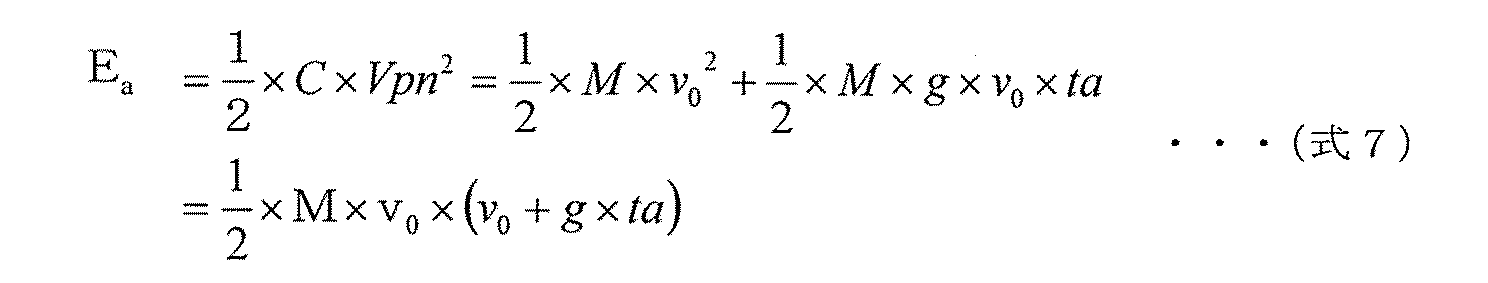
巻上加速期間(t≦ta)において必要となるエネルギーを蓄電部36に蓄電されている電気エネルギーによって補うために必要な充電エネルギーEa(J)は、蓄電部36の充電容量をC(F)、回生電圧をVpnとすると、上記(式5)(式6)より、下記(式7)で算出することができる。
Charging energy Ea (J) necessary for supplementing the energy required in the winding acceleration period (t ≦ ta) with the electrical energy stored in the
蓄電部36に必要な充電容量C(F)は、上記(式7)より、下記(式8)となる。
The charging capacity C (F) required for the
![]()
![]()
例えば、定格質量M=3000(kg)、巻上加速時間ta=2(s)、定格巻上速度v0=0.15(m/s)、回生電圧Vpn=370(V)、重力加速度g=9.8(m/s2)とすると、(式8)よりC=0.045(F)となる。蓄電部36の充電容量は、この値を満たすようにすればよい。
For example, rated mass M = 3000 (kg), hoisting acceleration time ta = 2 (s), rated hoisting speed v0 = 0.15 (m / s), regenerative voltage Vpn = 370 (V), gravitational acceleration g = Assuming 9.8 (m / s 2 ), C = 0.045 (F) from (Equation 8). The charging capacity of the
(3)巻上加速期間と定格速度巻上期間に必要となるエネルギーの合計
巻き上げ時の加速動作が完了し、定格速度v0(m/s)で荷物を巻き上げる距離をLu(m)、巻上動作時間をtu(s)とする。この期間(ta<t≦ta+tu)の巻上動作に必要な巻上エネルギーEu(J)およびLu(m)は、それぞれ下記(式9)(式10)で表される。
(3) Total energy required for hoisting acceleration period and rated speed hoisting period The acceleration operation at the time of hoisting is completed, and the distance for hoisting the load at the rated speed v0 (m / s) is Lu (m), hoisting Let the operating time be tu (s). The hoisting energy Eu (J) and Lu (m) necessary for the hoisting operation during this period (ta <t ≦ ta + tu) are expressed by the following (formula 9) and (formula 10), respectively.
![]()
![]()
![]()
![]()
巻上加速期間(t≦ta)および定格速度巻き上げ期間(ta<t≦ta+tu)において必要となるエネルギーを蓄電部36に蓄電されている電気エネルギーによって補うため蓄電部36が必要とする充電容量C(F)は、(式7)(式9)(式10)より、下記(式11)となる。
Charging capacity C required by the
![]()
![]()
定格質量M=3000(kg)、巻上加速時間ta=2(s)、定格巻上速度v0=0.15(m/s)、回生電圧Vpn=370(V)、定格速度巻上時間tu=10(s)、重力加速度g=9.8(m/s2)とすると、(式11)よりC=0.71(F)となる。蓄電部36の充電容量は、この値を満たすようにすればよい。
Rated mass M = 3000 (kg), hoisting acceleration time ta = 2 (s), rated hoisting speed v0 = 0.15 (m / s), regenerative voltage Vpn = 370 (V), rated speed hoisting time tu = 10 (s) and gravitational acceleration g = 9.8 (m / s 2 ), C = 0.71 (F) from (Equation 11). The charging capacity of the
巻上加速期間(t≦ta)と定格速度巻上期間(ta<t≦ta+tu)の双方において必要となるエネルギーを、蓄電部36が蓄電している電気エネルギーのみによって補おうとすると、蓄電部36の充電容量Cが大きくなり、部品コストが大幅に高くなる可能性がある。そこで、例えば巻上加速期間(t≦ta)において必要となるエネルギーのみ蓄電部36を用いて補うなどして、蓄電部36の充電容量Cを調整してもよい。
If the energy required in both the winding acceleration period (t ≦ ta) and the rated speed winding period (ta <t ≦ ta + tu) is to be supplemented only by the electrical energy stored in the
このとき、蓄電部36の充電容量Cは比較的小さくなるので、回生エネルギーを全て充電することができない可能性がある。その場合は、回生抵抗35を併用し、蓄電部36が充電しきれない分を熱エネルギーとして消費させるとよい。
At this time, since the charging capacity C of the
以上、本実施の形態2では、巻上用モータ131の巻き下げ動作によって生じる回生エネルギーおよび蓄電部36が必要とする容量について説明した。
As described above, in the second embodiment, the regenerative energy generated by the lowering operation of the hoisting
<実施の形態3>
本発明の実施の形態3では、巻上用モータ131の巻き下げ動作期間において生じる回生エネルギーを蓄電部36が充電する際の充電時間について検討する。なお、各機器の構成は実施の形態1と同様である。
<Embodiment 3>
In the third embodiment of the present invention, the charging time when the
一般に、巻上機100を用いて巻き下げる荷物は毎回異なる場合がある。そのため、巻き下げ時に生じる回生エネルギーを蓄電部36に充電させる量を各回で等しく維持するためには、巻き下げる荷物の質量差を考慮に入れて、必要な充電時間を検討しなければならない。同様に、巻き下げ速度の差も考慮に入れる必要がある。以下、その検討過程を説明する。
In general, the luggage to be wound using the hoisting
質量m(kg)の荷物が速度v(m/s)でLd’(m)の距離を巻下方向に移動する場合、移動時間をtd(s)とすれば、生じる回生エネルギーEd(J)は、上記(式4)より、下記(式12)となる。 When a load of mass m (kg) moves at a speed of v (m / s) and a distance of Ld ′ (m) in the winding direction, the regenerative energy Ed (J) generated when the movement time is td (s). From the above (Formula 4), the following (Formula 12) is obtained.
このとき蓄電部36に充電される充電エネルギーEd(J)は、下記(式13)で表される。
At this time, the charging energy Ed (J) charged in the
![]()
![]()
質量m(kg)の荷物を巻き下げた場合において、定格質量Mの荷物を巻き下げた場合の充電エネルギーEαと等しい充電エネルギーを得るために必要な充電時間tdは、上記(式4)(式12)(式13)より、下記(式14)で算出することができる。 The charging time td required to obtain the charging energy equal to the charging energy Eα when the load with the rated mass M is unwound when the load with the mass m (kg) is lowered is the above (formula 4) (formula 4) 12) From (Expression 13), it can be calculated by the following (Expression 14).
蓄電部36の充電容量C(F)は、(式8)または(式11)いずれかで算出される値から選択することができる。
The charging capacity C (F) of the
例えば、荷物質量m=M=3000(kg)、巻下速度v=v0=0.15(m/s)、回生電圧Vpn=370(V)、C=0.045(F)、重力加速度g=9.8(m/s2)とすると、td≒0.7(s)となる。同様に、荷物質量m=M/2=1500(kg)、巻下速度v=v0/2=0.075(m/s)とした場合、td≒2.8(s)となる。 回生エネルギーを蓄電部36に充電する時間tdは、以上の手順によって求められる。
For example, load mass m = M = 3000 (kg), unwinding speed v = v0 = 0.15 (m / s), regenerative voltage Vpn = 370 (V), C = 0.045 (F), gravitational acceleration g Assuming = 9.8 (m / s 2 ), td≈0.7 (s). Similarly, when the load mass m = M / 2 = 1500 (kg) and the unwinding speed v = v0 / 2 = 0.075 (m / s), td≈2.8 (s). The time td for charging the
以上、本実施の形態3では、巻上用モータ131の巻き下げ動作期間において生じる回生エネルギーを蓄電部36が充電する際の充電時間について説明した。
As described above, in the third embodiment, the charging time when the
<実施の形態4>
本発明の実施の形態4では、実施の形態2〜3で説明した事項に基づき、巻上・横行インバータ制御部152が各スイッチを切り替える動作を説明する。各機器の構成は、実施の形態1と同様である。
<Embodiment 4>
In the fourth embodiment of the present invention, an operation in which the hoisting / traverse
巻上・横行インバータ制御部152は、負荷判定部37より荷物質量mを取得し、駆動素子部33が出力する交流電圧の周波数などに基づき巻下速度vを取得し、さらには電圧モニタ部40からVpnを取得して、上記演算式を用いて充電時間tdを算出する。
The hoisting / traversing
巻上・横行インバータ制御部152は、巻上用モータ131が巻き下げ動作を行なうときは、充電時間tdの間だけスイッチSWc39をONにし、蓄電部36に回生エネルギーを充電させる。
When the hoisting
巻上・横行インバータ制御部152は、蓄電部36の充電が完了すると、スイッチSWc39をOFFにするとともにスイッチSWr38をONにし、回生抵抗35をいつでも接続できるようにしておく。
When the charging of the
回生エネルギーによって直流母線電圧Vpnが上昇して整流コンデンサ32に過電圧が印加されると、巻上用インバータ151が破損してしまう。そこで巻上・横行インバータ制御部152は、電圧モニタ部40の検出値を監視し、直流母線電圧Vpnが所定の閾値まで上昇した時点で、回生駆動スイッチ34をONにする。以後は、回生エネルギーは回生抵抗35で熱エネルギーとして消費され、直流母線間電圧Vpnは降下する。これにより、巻上用インバータ151の過電圧破損を防ぐことができる。
When the DC bus voltage Vpn rises due to regenerative energy and an overvoltage is applied to the rectifying
なお、巻上・横行インバータ制御部152は、より安全に巻上用インバータ151を動作させるため、蓄電部36の充電が完了した時点で、スイッチSWr38と回生駆動スイッチ34をともにONにしてもよい。
In order to operate the hoisting
<実施の形態5>
実施の形態2〜4では、巻上加速期間(t≦ta)または定格速度巻上期間(ta<t≦tu)において必要となるエネルギーを、一定速度vで巻き下げるときに生じる回生エネルギーで補うことを説明した。本発明の実施の形態5では、加速巻下期間および減速巻下期間について説明する。
<Embodiment 5>
In the second to fourth embodiments, the energy required in the winding acceleration period (t ≦ ta) or the rated speed winding period (ta <t ≦ tu) is supplemented with the regenerative energy generated when lowering at a constant speed v. I explained that. In the fifth embodiment of the present invention, an acceleration lowering period and a deceleration lowering period will be described.
図4の「巻下動作」期間では、一定速度vで荷物を巻き下げる期間の前後で、加速巻下期間および減速巻下期間が存在する。加速巻下期間は、荷物が静止している状態から、巻下速度が一定速度vに達するまでの期間である。減速巻下期間は、一定速度vで荷物を巻き下げている状態から、荷物を静止させるまでの期間である。 In the “rolling-down operation” period of FIG. 4, there are an acceleration winding-down period and a deceleration winding-down period before and after the period for winding down the load at a constant speed v. The acceleration lowering period is a period from when the load is stationary until the lowering speed reaches a constant speed v. The deceleration lowering period is a period from when the load is being lowered at a constant speed v until the load is stopped.
減速巻下期間があまりにも長いと、オペレータが荷物の巻き下げを停止するよう指示してから実際に荷物が静止するまでの時間が長くなり、荷物が地面などに衝突する可能性があるため、危険である。そこで、減速巻下期間は例えば0.5(s)程度の短い時間に設定されることが望ましい。 If the deceleration unwinding period is too long, the time from when the operator instructs to stop unloading the baggage until the baggage actually stops, and the baggage may collide with the ground, etc. It is a danger. Therefore, it is desirable to set the deceleration lowering period to a short time of about 0.5 (s), for example.
これに起因して、減速巻下期間では、巻上用モータ131の出力を大きくしてトルクを上げる必要がある。そのため、短い時間に大きな回生エネルギーが生じることになるので、過電圧が生じやすいといえる。
Due to this, it is necessary to increase the torque by increasing the output of the hoisting
そこで、巻上・横行インバータ制御部152は、減速巻下期間では常にスイッチSWr38と回生駆動スイッチ34をともにONにし、回生エネルギーが回生抵抗35で確実に消費されるようにしてもよい。
Therefore, the hoisting / traverse
減速巻下期間と比較して、加速巻下期間に対する時間的制約は比較的緩いため、例えば加速巻下期間を長めに確保することにより、急激な電圧上昇を防ぐことができる。 Compared with the deceleration lowering period, the time restriction on the acceleration lowering period is relatively loose. Therefore, for example, by ensuring a longer acceleration lowering period, a rapid voltage increase can be prevented.
また、以上の実施の形態2〜4では、一定速度vで巻き下げるときに生じる回生エネルギーを蓄電部36に充電させることを説明したが、加速巻下期間または減速巻下期間で生じる回生エネルギーを充電させてもよい。
Further, in the above-described
<実施の形態6>
以上の実施の形態1〜5で説明した、回生エネルギーを蓄電部36に充電させて有効利用する手法は、走行用モータ210をモータブレーキ250で停止させるときに生じる回生エネルギーなどについても同様に適用することができる。
<Embodiment 6>
The method of effectively using the regenerative energy by charging the
ただし、走行用装置200は、オペレータが入力装置300を用いて走行用装置200を停止させるよう指示してから実際に停止するまでの時間間隔に対する制約が緩いため、巻上機100と比較して回生エネルギーはあまり生じない。そのため回生エネルギーを有効利用する観点からは、大きな効果は得にくいといえる。
However, the traveling
100:巻上機、110:クレーンフック、120:ワイヤロープ、130:巻上用装置、131:巻上用モータ、132:巻上ドラム、140:横行用装置、141:横行用モータ、150:巻上横行インバータ装置、151:巻上用インバータ、152:巻上・横行用インバータ制御部、153:横行用インバータ、161〜162:モータブレーキ、200:走行用装置、210:走行用モータ、220:横行用ガーダー、230:走行用インバータ装置、231:走行インバータ制御部、232:走行用インバータ、240:走行用ガーダー、250:モータブレーキ、300:入力装置、31:整流部、32:整流コンデンサ、33:駆動素子部、34:回生駆動スイッチ、35:回生抵抗、36:蓄電部、37:負荷判別部、38:スイッチSwr、39:スイッチSWc、40:電圧モニタ部、1000:クレーン装置。 100: hoisting machine, 110: crane hook, 120: wire rope, 130: hoisting device, 131: hoisting motor, 132: hoisting drum, 140: traversing device, 141: traversing motor, 150: Hoisting and traverse inverter device, 151: hoisting inverter, 152: hoisting / traversing inverter control unit, 153: traversing inverter, 161-162: motor brake, 200: traveling device, 210: traveling motor, 220 : Traveling girder, 230: Traveling inverter device, 231: Traveling inverter control unit, 232: Traveling inverter, 240: Traveling girder, 250: Motor brake, 300: Input device, 31: Rectification unit, 32: Rectification capacitor 33: drive element unit, 34: regenerative drive switch, 35: regenerative resistor, 36: power storage unit, 37: load determination unit, 3 : Switches Swr, 39: switch SWc, 40: voltage monitor unit, 1000: crane apparatus.
Claims (7)
巻上動作と巻下動作を行なうモータと、
前記モータが巻下動作を行なうときに生じる回生電力を蓄電する蓄電装置と、
を備えたことを特徴とする巻上機。 A hoisting machine for hoisting and lowering luggage,
A motor that performs hoisting and lowering operations;
A power storage device that stores regenerative power generated when the motor performs a lowering operation;
A hoisting machine characterized by comprising:
前記第1スイッチを制御する制御部と、
を備えたことを特徴とする請求項1記載の巻上機。 A first switch for switching whether to connect the power storage device and the motor;
A control unit for controlling the first switch;
The hoist according to claim 1, further comprising:
前記モータが前記巻上動作を行なう期間のうち前記モータを加速する期間において、
前記第1スイッチをONにして前記蓄電装置と前記モータを接続し前記蓄電装置が蓄積している電力を前記モータに供給する
ことを特徴とする請求項2記載の巻上機。 The controller is
In the period in which the motor accelerates the motor among the period in which the motor performs the hoisting operation,
The hoisting machine according to claim 2, wherein the first switch is turned on to connect the power storage device and the motor, and the power stored in the power storage device is supplied to the motor.
前記モータが前記巻上動作を行なう期間のうち前記モータを加速する期間において前記モータが必要とする電力を蓄積することができる容量を有し、
前記制御部は、
前記モータが巻下動作を行なうとき前記第1スイッチをONにして前記回生電力を前記蓄電装置に蓄積する
ことを特徴とする請求項3記載の巻上機。 The power storage device
The motor has a capacity capable of accumulating electric power required by the motor in a period of accelerating the motor in a period of performing the hoisting operation,
The controller is
The hoisting machine according to claim 3, wherein when the motor performs a lowering operation, the first switch is turned on to accumulate the regenerative power in the power storage device.
ことを特徴とする請求項1から請求項4のいずれか1項に記載の巻上機。 The hoisting machine according to any one of claims 1 to 4, further comprising a regenerative resistor that consumes regenerative power generated when the motor performs a lowering operation.
前記制御部は、
前記回生電力が前記蓄電装置の容量を超えて生じるときは、
前記第2スイッチをONにして余剰の前記回生電力を前記回生抵抗で消費させる
ことを特徴とする請求項5記載の巻上機。 A second switch for switching whether to connect the regenerative resistor and the motor;
The controller is
When the regenerative power occurs beyond the capacity of the power storage device,
The hoisting machine according to claim 5, wherein the second switch is turned on so that the excessive regenerative power is consumed by the regenerative resistor.
前記第2スイッチがONになっている状態で前記回生抵抗を前記モータに接続するか否かをさらに切り替える第3スイッチと、
前記インバータの直流母線間電圧を検出する電圧モニタ部と、
を備え、
前記制御部は、
前記回生電力が前記蓄電装置の容量を超えて生じるときは、
前記第2スイッチをONにするとともに前記第3スイッチをOFFにして前記回生抵抗を前記モータから切断しておき、
前記直流母線間電圧が所定閾値以上となった時点で前記第3スイッチをONにして余剰の前記回生電力を前記回生抵抗で消費させる
ことを特徴とする請求項6記載の巻上機。 An inverter for driving the motor;
A third switch for further switching whether or not to connect the regenerative resistor to the motor in a state where the second switch is ON;
A voltage monitoring unit for detecting a voltage between the DC buses of the inverter;
With
The controller is
When the regenerative power occurs beyond the capacity of the power storage device,
Turn on the second switch and turn off the third switch to disconnect the regenerative resistor from the motor,
The hoisting machine according to claim 6, wherein when the voltage between the DC buses becomes equal to or greater than a predetermined threshold, the third switch is turned on to consume the excessive regenerative power by the regenerative resistor.
Priority Applications (2)
| Application Number | Priority Date | Filing Date | Title |
|---|---|---|---|
| JP2010000241A JP2011136838A (en) | 2010-01-04 | 2010-01-04 | Hoisting machine |
| CN2011100038611A CN102115015A (en) | 2010-01-04 | 2011-01-04 | Hoister |
Applications Claiming Priority (1)
| Application Number | Priority Date | Filing Date | Title |
|---|---|---|---|
| JP2010000241A JP2011136838A (en) | 2010-01-04 | 2010-01-04 | Hoisting machine |
Publications (1)
| Publication Number | Publication Date |
|---|---|
| JP2011136838A true JP2011136838A (en) | 2011-07-14 |
Family
ID=44213963
Family Applications (1)
| Application Number | Title | Priority Date | Filing Date |
|---|---|---|---|
| JP2010000241A Abandoned JP2011136838A (en) | 2010-01-04 | 2010-01-04 | Hoisting machine |
Country Status (2)
| Country | Link |
|---|---|
| JP (1) | JP2011136838A (en) |
| CN (1) | CN102115015A (en) |
Cited By (4)
| Publication number | Priority date | Publication date | Assignee | Title |
|---|---|---|---|---|
| JP2013110783A (en) * | 2011-11-17 | 2013-06-06 | Mitsubishi Heavy Industries Machinery Technology Corp | Power supply apparatus and supply power control method |
| JP2014025517A (en) * | 2012-07-26 | 2014-02-06 | Shinko Engineering Co Ltd | Electric motor with brake |
| JP2014043354A (en) * | 2006-10-25 | 2014-03-13 | Yaskawa Electric Corp | Crane device and control method for the same |
| KR101615972B1 (en) * | 2016-02-04 | 2016-04-28 | 남상규 | Compact type hoist capable of using regenerated energy |
Families Citing this family (6)
| Publication number | Priority date | Publication date | Assignee | Title |
|---|---|---|---|---|
| JP5848975B2 (en) * | 2012-01-20 | 2016-01-27 | 株式会社日立産機システム | Electric hoist and control method thereof |
| CN104210982B (en) * | 2014-08-22 | 2016-05-25 | 上海吉亿电机有限公司 | A kind of elevator internal contracting brake control system and control method |
| JP6623112B2 (en) * | 2016-04-15 | 2019-12-18 | 株式会社日立産機システム | Hoisting machine and control method of hoisting machine |
| CN111224588B (en) * | 2020-01-07 | 2023-06-27 | 深圳市显控科技股份有限公司 | Servo driver regeneration control method, system, equipment and storage medium |
| CN114772493A (en) * | 2022-03-15 | 2022-07-22 | 浙江三一装备有限公司 | Control method and system of winch system and operation machine |
| CN116374869A (en) * | 2023-03-28 | 2023-07-04 | 北京航天发射技术研究所 | An erecting electric drive system and launch platform |
Family Cites Families (4)
| Publication number | Priority date | Publication date | Assignee | Title |
|---|---|---|---|---|
| US7165654B2 (en) * | 2004-02-06 | 2007-01-23 | Paceco Corp | Energy storage method for load hoisting machinery |
| JP2005324886A (en) * | 2004-05-12 | 2005-11-24 | Toshiba Elevator Co Ltd | Control device of hybrid drive type elevator |
| JP4787539B2 (en) * | 2005-05-20 | 2011-10-05 | 株式会社Ihi | Load drive device |
| CN1945963A (en) * | 2006-09-01 | 2007-04-11 | 罗中柱 | DC bus powered crane power system |
-
2010
- 2010-01-04 JP JP2010000241A patent/JP2011136838A/en not_active Abandoned
-
2011
- 2011-01-04 CN CN2011100038611A patent/CN102115015A/en active Pending
Cited By (4)
| Publication number | Priority date | Publication date | Assignee | Title |
|---|---|---|---|---|
| JP2014043354A (en) * | 2006-10-25 | 2014-03-13 | Yaskawa Electric Corp | Crane device and control method for the same |
| JP2013110783A (en) * | 2011-11-17 | 2013-06-06 | Mitsubishi Heavy Industries Machinery Technology Corp | Power supply apparatus and supply power control method |
| JP2014025517A (en) * | 2012-07-26 | 2014-02-06 | Shinko Engineering Co Ltd | Electric motor with brake |
| KR101615972B1 (en) * | 2016-02-04 | 2016-04-28 | 남상규 | Compact type hoist capable of using regenerated energy |
Also Published As
| Publication number | Publication date |
|---|---|
| CN102115015A (en) | 2011-07-06 |
Similar Documents
| Publication | Publication Date | Title |
|---|---|---|
| JP2011136838A (en) | Hoisting machine | |
| JP5240685B2 (en) | elevator | |
| JP5800159B2 (en) | Crane apparatus and control method thereof | |
| JP2009242088A (en) | Crane device | |
| JP4698644B2 (en) | Crane equipment | |
| JP2012500166A (en) | Management of power from multiple sources in an elevator power system. | |
| CN102714424B (en) | Power-supply device, crane, and power-supply method | |
| JP2012500164A (en) | Control of elevator drive line current and energy storage | |
| JP5241367B2 (en) | Electric hoist | |
| JP2011068499A (en) | Crane device | |
| JP2020158286A (en) | Elevator power supply system and elevator power supply method | |
| JP5410728B2 (en) | CRANE DEVICE AND CRANE DEVICE CONTROL METHOD | |
| JP2012071903A (en) | Hybrid drive device, crane control device and crane device | |
| JP5805297B2 (en) | Elevator equipment | |
| CN103596868A (en) | Elevator control device | |
| JP2012012149A (en) | Crane control device and crane device | |
| EP4242157A2 (en) | Automatic rescue and charging system for elevator drive | |
| JP5839873B2 (en) | Control device for hybrid drive elevator | |
| JP5501594B2 (en) | CRANE DEVICE AND CRANE DEVICE CONTROL METHOD | |
| JP5277115B2 (en) | Parking equipment | |
| JP5935301B2 (en) | Power supply apparatus and supply power control method | |
| JP2005102410A (en) | Elevator control device | |
| JP2014009041A (en) | Elevator control device | |
| JP5622211B2 (en) | Hybrid cargo handling equipment | |
| JP5412842B2 (en) | Crane system and control method thereof |
Legal Events
| Date | Code | Title | Description |
|---|---|---|---|
| A621 | Written request for application examination |
Free format text: JAPANESE INTERMEDIATE CODE: A621 Effective date: 20120528 |
|
| A762 | Written abandonment of application |
Free format text: JAPANESE INTERMEDIATE CODE: A762 Effective date: 20130624 |
|
| A977 | Report on retrieval |
Free format text: JAPANESE INTERMEDIATE CODE: A971007 Effective date: 20130628 |