JP5719745B2 - Fluid mixer and heat exchange system using the same - Google Patents
Fluid mixer and heat exchange system using the same Download PDFInfo
- Publication number
- JP5719745B2 JP5719745B2 JP2011223820A JP2011223820A JP5719745B2 JP 5719745 B2 JP5719745 B2 JP 5719745B2 JP 2011223820 A JP2011223820 A JP 2011223820A JP 2011223820 A JP2011223820 A JP 2011223820A JP 5719745 B2 JP5719745 B2 JP 5719745B2
- Authority
- JP
- Japan
- Prior art keywords
- fluid
- mixing
- main body
- pipe
- gas
- Prior art date
- Legal status (The legal status is an assumption and is not a legal conclusion. Google has not performed a legal analysis and makes no representation as to the accuracy of the status listed.)
- Active
Links
- 239000012530 fluid Substances 0.000 title claims description 120
- 230000002093 peripheral effect Effects 0.000 claims description 36
- 238000011144 upstream manufacturing Methods 0.000 claims description 12
- 239000007789 gas Substances 0.000 description 108
- 238000010438 heat treatment Methods 0.000 description 40
- 230000001737 promoting effect Effects 0.000 description 18
- 238000009826 distribution Methods 0.000 description 17
- 239000000446 fuel Substances 0.000 description 11
- VNWKTOKETHGBQD-UHFFFAOYSA-N methane Chemical compound C VNWKTOKETHGBQD-UHFFFAOYSA-N 0.000 description 10
- 238000000605 extraction Methods 0.000 description 9
- 230000003197 catalytic effect Effects 0.000 description 7
- 238000010586 diagram Methods 0.000 description 6
- 238000010792 warming Methods 0.000 description 5
- KDLHZDBZIXYQEI-UHFFFAOYSA-N Palladium Chemical compound [Pd] KDLHZDBZIXYQEI-UHFFFAOYSA-N 0.000 description 4
- 239000003245 coal Substances 0.000 description 4
- 238000004519 manufacturing process Methods 0.000 description 4
- BASFCYQUMIYNBI-UHFFFAOYSA-N platinum Chemical compound [Pt] BASFCYQUMIYNBI-UHFFFAOYSA-N 0.000 description 4
- 239000003054 catalyst Substances 0.000 description 3
- 230000000052 comparative effect Effects 0.000 description 3
- 230000006835 compression Effects 0.000 description 3
- 238000007906 compression Methods 0.000 description 3
- 238000007792 addition Methods 0.000 description 2
- 238000006555 catalytic reaction Methods 0.000 description 2
- 238000009434 installation Methods 0.000 description 2
- 229910052763 palladium Inorganic materials 0.000 description 2
- 229910052697 platinum Inorganic materials 0.000 description 2
- 239000007858 starting material Substances 0.000 description 2
- 238000012546 transfer Methods 0.000 description 2
- 238000009423 ventilation Methods 0.000 description 2
- 230000004913 activation Effects 0.000 description 1
- 238000009412 basement excavation Methods 0.000 description 1
- 238000007084 catalytic combustion reaction Methods 0.000 description 1
- 239000003638 chemical reducing agent Substances 0.000 description 1
- 239000000567 combustion gas Substances 0.000 description 1
- 238000012217 deletion Methods 0.000 description 1
- 230000037430 deletion Effects 0.000 description 1
- 239000000463 material Substances 0.000 description 1
- 238000012986 modification Methods 0.000 description 1
- 230000004048 modification Effects 0.000 description 1
- 238000013021 overheating Methods 0.000 description 1
- 238000010248 power generation Methods 0.000 description 1
- 230000002265 prevention Effects 0.000 description 1
- 238000010926 purge Methods 0.000 description 1
- 230000003584 silencer Effects 0.000 description 1
- 238000012795 verification Methods 0.000 description 1
- 238000003466 welding Methods 0.000 description 1
Images


Classifications
-
- B—PERFORMING OPERATIONS; TRANSPORTING
- B01—PHYSICAL OR CHEMICAL PROCESSES OR APPARATUS IN GENERAL
- B01F—MIXING, e.g. DISSOLVING, EMULSIFYING OR DISPERSING
- B01F25/00—Flow mixers; Mixers for falling materials, e.g. solid particles
- B01F25/30—Injector mixers
- B01F25/31—Injector mixers in conduits or tubes through which the main component flows
-
- B—PERFORMING OPERATIONS; TRANSPORTING
- B01—PHYSICAL OR CHEMICAL PROCESSES OR APPARATUS IN GENERAL
- B01F—MIXING, e.g. DISSOLVING, EMULSIFYING OR DISPERSING
- B01F23/00—Mixing according to the phases to be mixed, e.g. dispersing or emulsifying
- B01F23/10—Mixing gases with gases
-
- B—PERFORMING OPERATIONS; TRANSPORTING
- B01—PHYSICAL OR CHEMICAL PROCESSES OR APPARATUS IN GENERAL
- B01F—MIXING, e.g. DISSOLVING, EMULSIFYING OR DISPERSING
- B01F25/00—Flow mixers; Mixers for falling materials, e.g. solid particles
- B01F25/30—Injector mixers
- B01F25/31—Injector mixers in conduits or tubes through which the main component flows
- B01F25/314—Injector mixers in conduits or tubes through which the main component flows wherein additional components are introduced at the circumference of the conduit
- B01F25/3141—Injector mixers in conduits or tubes through which the main component flows wherein additional components are introduced at the circumference of the conduit with additional mixing means other than injector mixers
-
- B—PERFORMING OPERATIONS; TRANSPORTING
- B01—PHYSICAL OR CHEMICAL PROCESSES OR APPARATUS IN GENERAL
- B01F—MIXING, e.g. DISSOLVING, EMULSIFYING OR DISPERSING
- B01F25/00—Flow mixers; Mixers for falling materials, e.g. solid particles
- B01F25/40—Static mixers
- B01F25/42—Static mixers in which the mixing is affected by moving the components jointly in changing directions, e.g. in tubes provided with baffles or obstructions
- B01F25/43—Mixing tubes, e.g. wherein the material is moved in a radial or partly reversed direction
- B01F25/435—Mixing tubes composed of concentric tubular members
-
- F—MECHANICAL ENGINEERING; LIGHTING; HEATING; WEAPONS; BLASTING
- F02—COMBUSTION ENGINES; HOT-GAS OR COMBUSTION-PRODUCT ENGINE PLANTS
- F02C—GAS-TURBINE PLANTS; AIR INTAKES FOR JET-PROPULSION PLANTS; CONTROLLING FUEL SUPPLY IN AIR-BREATHING JET-PROPULSION PLANTS
- F02C6/00—Plural gas-turbine plants; Combinations of gas-turbine plants with other apparatus; Adaptations of gas-turbine plants for special use
- F02C6/18—Plural gas-turbine plants; Combinations of gas-turbine plants with other apparatus; Adaptations of gas-turbine plants for special use using the waste heat of gas-turbine plants outside the plants themselves, e.g. gas-turbine power heat plants
-
- F—MECHANICAL ENGINEERING; LIGHTING; HEATING; WEAPONS; BLASTING
- F02—COMBUSTION ENGINES; HOT-GAS OR COMBUSTION-PRODUCT ENGINE PLANTS
- F02C—GAS-TURBINE PLANTS; AIR INTAKES FOR JET-PROPULSION PLANTS; CONTROLLING FUEL SUPPLY IN AIR-BREATHING JET-PROPULSION PLANTS
- F02C7/00—Features, components parts, details or accessories, not provided for in, or of interest apart form groups F02C1/00 - F02C6/00; Air intakes for jet-propulsion plants
- F02C7/08—Heating air supply before combustion, e.g. by exhaust gases
- F02C7/10—Heating air supply before combustion, e.g. by exhaust gases by means of regenerative heat-exchangers
-
- F—MECHANICAL ENGINEERING; LIGHTING; HEATING; WEAPONS; BLASTING
- F28—HEAT EXCHANGE IN GENERAL
- F28D—HEAT-EXCHANGE APPARATUS, NOT PROVIDED FOR IN ANOTHER SUBCLASS, IN WHICH THE HEAT-EXCHANGE MEDIA DO NOT COME INTO DIRECT CONTACT
- F28D21/00—Heat-exchange apparatus not covered by any of the groups F28D1/00 - F28D20/00
- F28D21/0001—Recuperative heat exchangers
- F28D21/0003—Recuperative heat exchangers the heat being recuperated from exhaust gases
- F28D21/001—Recuperative heat exchangers the heat being recuperated from exhaust gases for thermal power plants or industrial processes
-
- F—MECHANICAL ENGINEERING; LIGHTING; HEATING; WEAPONS; BLASTING
- F28—HEAT EXCHANGE IN GENERAL
- F28F—DETAILS OF HEAT-EXCHANGE AND HEAT-TRANSFER APPARATUS, OF GENERAL APPLICATION
- F28F13/00—Arrangements for modifying heat-transfer, e.g. increasing, decreasing
- F28F13/06—Arrangements for modifying heat-transfer, e.g. increasing, decreasing by affecting the pattern of flow of the heat-exchange media
- F28F13/12—Arrangements for modifying heat-transfer, e.g. increasing, decreasing by affecting the pattern of flow of the heat-exchange media by creating turbulence, e.g. by stirring, by increasing the force of circulation
- F28F13/125—Arrangements for modifying heat-transfer, e.g. increasing, decreasing by affecting the pattern of flow of the heat-exchange media by creating turbulence, e.g. by stirring, by increasing the force of circulation by stirring
-
- F—MECHANICAL ENGINEERING; LIGHTING; HEATING; WEAPONS; BLASTING
- F05—INDEXING SCHEMES RELATING TO ENGINES OR PUMPS IN VARIOUS SUBCLASSES OF CLASSES F01-F04
- F05B—INDEXING SCHEME RELATING TO WIND, SPRING, WEIGHT, INERTIA OR LIKE MOTORS, TO MACHINES OR ENGINES FOR LIQUIDS COVERED BY SUBCLASSES F03B, F03D AND F03G
- F05B2220/00—Application
- F05B2220/60—Application making use of surplus or waste energy
-
- F—MECHANICAL ENGINEERING; LIGHTING; HEATING; WEAPONS; BLASTING
- F05—INDEXING SCHEMES RELATING TO ENGINES OR PUMPS IN VARIOUS SUBCLASSES OF CLASSES F01-F04
- F05D—INDEXING SCHEME FOR ASPECTS RELATING TO NON-POSITIVE-DISPLACEMENT MACHINES OR ENGINES, GAS-TURBINES OR JET-PROPULSION PLANTS
- F05D2260/00—Function
- F05D2260/20—Heat transfer, e.g. cooling
- F05D2260/221—Improvement of heat transfer
- F05D2260/2212—Improvement of heat transfer by creating turbulence
Landscapes
- Engineering & Computer Science (AREA)
- Chemical & Material Sciences (AREA)
- Mechanical Engineering (AREA)
- General Engineering & Computer Science (AREA)
- Chemical Kinetics & Catalysis (AREA)
- Combustion & Propulsion (AREA)
- Physics & Mathematics (AREA)
- Thermal Sciences (AREA)
- Dispersion Chemistry (AREA)
Description
本発明は、例えば、高温流体と低温流体のような異なる2つの流体の流れを均一に混合する流体混合器に関するものである。 The present invention relates to a fluid mixer that uniformly mixes two different fluid flows, such as a hot fluid and a cold fluid.
複数の流体を混合する混合器では、混合後の温度分布やガス濃度分布が均一であることが望まれる。例えば、混合器の下流にタービンや熱交換器が配置される場合では、混合ガスの温度分布が均一でないと、タービン翼や伝熱管に不均一な熱ひずみに起因した応力が生じ、その結果、タービンや伝熱管の寿命を短くしてしまう。また、機器の効率も低下してしまう。 In a mixer that mixes a plurality of fluids, it is desirable that the temperature distribution and gas concentration distribution after mixing be uniform. For example, in the case where a turbine or heat exchanger is arranged downstream of the mixer, if the temperature distribution of the mixed gas is not uniform, stress due to non-uniform thermal strain occurs in the turbine blades and heat transfer tubes. This will shorten the life of the turbine and heat transfer tubes. In addition, the efficiency of the device is reduced.
そこで、混合促進を目的として、流体の流れ場に乱流を促進させるリブを設ける構造や、流れを強制的に偏向させて2つの流体の流れを重ね合わせる構造のものが知られている(特許文献1)。このような構造では、配管の圧力損失が大きくなり、また構造も複雑になり、製造コストも増大する。高温の流体を用いる場合、高温流体に接触する部材の耐熱性が求められ、製造コストがさらに増大する。また、2つの流体を流れる配管をT字型に接続して、簡単な構造で2つの流体を混合させるようにしたものもあり(特許文献2)、これによれば、製造コストが低下する。 Therefore, for the purpose of promoting mixing, a structure in which a rib for promoting turbulent flow is provided in a fluid flow field, or a structure in which two fluid flows are superposed by forcibly deflecting the flow (patented) Reference 1). In such a structure, the pressure loss of the piping becomes large, the structure becomes complicated, and the manufacturing cost increases. When using a high temperature fluid, the heat resistance of the member which contacts a high temperature fluid is calculated | required, and manufacturing cost further increases. In addition, there is a pipe in which two fluids are connected in a T-shape so that the two fluids are mixed with a simple structure (Patent Document 2). According to this, the manufacturing cost is reduced.
しかしながら、上記特許文献2の流体混合器は、構造は簡単であるが、流体が互いに直角に交わるから、十分均一な混合状態を作り出すことが難しい。
However, although the fluid mixer disclosed in
本発明は、前記課題に鑑みてなされたもので、簡単な構造でありながら、均一な混合が可能で、かつ圧力損失を抑制できる流体混合器を提供することを目的としている。 The present invention has been made in view of the above problems, and an object of the present invention is to provide a fluid mixer capable of uniform mixing and suppressing pressure loss while having a simple structure.
上記目的を達成するために、本発明にかかる流体混合器は、内側で第1と第2の流体を混合する中空筒状の本体と、前記本体の上流側端部に設けられて前記第1の流体を流入させる第1の流入口と、前記本体の内側に配置され、前記第1の流体の流れる方向に沿った軸心を有する中空筒状の混合促進体と、前記本体の周壁に設けられて前記混合促進体の外周面に向かって前記第2の流体を流入させる第2の流入口とを備える。 In order to achieve the above object, a fluid mixer according to the present invention includes a hollow cylindrical main body that mixes a first fluid and a second fluid inside, and an upstream end of the main body. Provided on the peripheral wall of the main body, a hollow cylindrical mixing promoting body that is disposed inside the main body and has an axial center along the flow direction of the first fluid. And a second inflow port for allowing the second fluid to flow toward the outer peripheral surface of the mixing promoting body.
この構成によれば、第1の流体の流れる方向に沿った軸心を有する混合促進体が本体の内側に配置されているから、第2の流体が混合促進体の外周面に向かって導入されるので、第2の流体は混合促進体の外周面に衝突して本体の周方向の全域に回りこむことで、混合促進体の外側において第1の流体と第2の流体とが十分混合される。第2の流体は、混合促進体の外側を流れる第1の流体と混合された後、混合促進体の下流で、混合促進体の内側を流れる第1の流体と再度混合されることで、第1の流体と第2の流体との混合が促進される。また、第1の流体が中空筒状の混合促進体の軸心方向に沿って流れるから、第1の流体の圧力損失を抑制することができる。さらに、本体の内側に混合促進体を配置し、この混合促進体に向かって第2の流体を導入する第2の流入口を配置するだけであるから、構造が簡単である。 According to this configuration, since the mixing promoting body having an axis along the direction in which the first fluid flows is disposed inside the main body, the second fluid is introduced toward the outer peripheral surface of the mixing promoting body. Therefore, the second fluid collides with the outer peripheral surface of the mixing promoting body and wraps around the entire circumferential direction of the main body, so that the first fluid and the second fluid are sufficiently mixed outside the mixing promoting body. The The second fluid is mixed with the first fluid flowing outside the mixing accelerator and then mixed again with the first fluid flowing inside the mixing accelerator downstream of the mixing accelerator. Mixing of the first fluid and the second fluid is facilitated. Moreover, since the 1st fluid flows along the axial center direction of a hollow cylindrical mixing promotion body, the pressure loss of the 1st fluid can be suppressed. Furthermore, the structure is simple because the mixing accelerator is disposed inside the main body and the second inlet for introducing the second fluid toward the mixing accelerator is only disposed.
本発明において、前記混合促進体が前記本体とほぼ同心に配置されていることが好ましい。この構成によれば、第2の流入口の本体周方向の設置位置に関わらず、第2の流入口と混合促進体の距離が一定となり、第2の流入口と混合促進体の位置関係に正確性が要求されなくなる結果、製造が容易になる。 In the present invention, it is preferable that the mixing promoting body is disposed substantially concentrically with the main body. According to this configuration, the distance between the second inlet and the mixing accelerator is constant regardless of the installation position of the second inlet in the circumferential direction of the main body, and the positional relationship between the second inlet and the mixing accelerator is the same. Manufacturing is facilitated as a result of not requiring accuracy.
本発明において、前記本体を形成する第1の配管に、前記第2の流入口に第2の流体を供給する第2の配管が直交して接続されていることが好ましい。この構成によれば、第2の流体が混合促進体に、その軸心に直交する向きに衝突するから、第2の流体が混合促進体の外周面全体に回り込み、その結果、第1の流体と第2の流体との混合が一層促進される。 In the present invention, it is preferable that a second pipe for supplying a second fluid to the second inflow port is orthogonally connected to the first pipe forming the main body. According to this configuration, since the second fluid collides with the mixing accelerator in a direction orthogonal to the axis thereof, the second fluid wraps around the entire outer peripheral surface of the mixing accelerator, and as a result, the first fluid And the second fluid are further mixed.
本発明において、前記本体を形成する第1の配管に、前記第2の流入口に前記第2の流体を供給する第2の配管が接続され、その接続部における前記第2の配管の端縁が前記第1の配管の内周面と面一またはこれよりも径方向外方に配置されていることが好ましい。この構成によれば、第2の配管により、第1の配管を流れる第1の流体の流れが阻害されることがなくなり、配管の圧力損失が一層抑制される。 In the present invention, a second pipe for supplying the second fluid to the second inflow port is connected to the first pipe forming the main body, and an edge of the second pipe at the connection portion Is preferably disposed flush with the inner circumferential surface of the first pipe or radially outward from the inner circumferential surface. According to this configuration, the second pipe does not hinder the flow of the first fluid flowing through the first pipe, and the pressure loss of the pipe is further suppressed.
本発明において、前記第1の流体は前記第2の流体よりも低温であることが好ましい。この構成によれば、第1の流体により、混合促進体の表面全体が冷却されるから、混合促進体の過熱を防ぐための構造を別途設ける必要がなく、構造が一層簡単になる。 In the present invention, it is preferable that the first fluid has a lower temperature than the second fluid. According to this configuration, since the entire surface of the mixing accelerator is cooled by the first fluid, it is not necessary to separately provide a structure for preventing the mixing accelerator from overheating, and the structure is further simplified.
本発明において、前記本体における下流部が、下流に向かって通路面積が増大する拡径部により形成されていることが好ましい。この構成によれば、拡径部により混合流体が拡散され、混合が一層促進される。 In this invention, it is preferable that the downstream part in the said main body is formed of the enlarged diameter part from which a passage area increases toward the downstream. According to this configuration, the mixed fluid is diffused by the enlarged diameter portion, and mixing is further promoted.
本発明にかかる熱交換システムは、本発明の流体混合器が、熱交換器の上流側に配置されてなる。この構成によれば、上記流体混合器により2つの流体が十分に混合された後、混合流体が熱交換器に導かれるので、混合流体の流れと直交する断面での温度分布が均一化される結果、熱交換効率が向上する。 In the heat exchange system according to the present invention, the fluid mixer of the present invention is arranged on the upstream side of the heat exchanger. According to this configuration, after the two fluids are sufficiently mixed by the fluid mixer, the mixed fluid is guided to the heat exchanger, so that the temperature distribution in the cross section orthogonal to the flow of the mixed fluid is made uniform. As a result, the heat exchange efficiency is improved.
本発明の流体混合器によれば、第2の流入口から流入した第2の流体は、混合促進体の外周面に衝突して本体の周方向の全域に回りこむことで、混合促進体の外側において第1の流体と十分混合される。第2の流体は、さらに混合促進体の下流で、混合促進体の内側を流れる第1の流体と再度混合されることで、混合が促進される。また、第1の流体が中空筒状の混合促進体の軸心方向に沿って流れるから、第1の流体の圧力損失を抑制することができる。さらに、本体の内側に混合促進体を配置し、この混合促進体に向かって第2の流体を導入する第2の流入口を配置するだけであるから、構造が簡単である。 According to the fluid mixer of the present invention, the second fluid that has flowed in from the second inflow port collides with the outer peripheral surface of the mixing accelerator and wraps around the entire area in the circumferential direction of the main body. Fully mixed with the first fluid on the outside. The second fluid is further mixed with the first fluid flowing inside the mixing accelerator downstream of the mixing accelerator, thereby promoting mixing. Moreover, since the 1st fluid flows along the axial center direction of a hollow cylindrical mixing promotion body, the pressure loss of the 1st fluid can be suppressed. Furthermore, the structure is simple because the mixing accelerator is disposed inside the main body and the second inlet for introducing the second fluid toward the mixing accelerator is only disposed.
以下、本発明の好ましい実施形態を図面に基づいて説明する。図1は本発明の一実施形態にかかる流体混合器を備えた希薄燃料吸入ガスタービンを示す簡略構成図である。このガスタービンGTは、圧縮機1、白金やパラジウムなどの触媒を含む触媒燃焼器2、およびタービン3を有している。このガスタービンGTの出力により、発電機とスタータを兼ねる回転機4が駆動される。
Hereinafter, preferred embodiments of the present invention will be described with reference to the drawings. FIG. 1 is a simplified configuration diagram showing a lean fuel intake gas turbine including a fluid mixer according to an embodiment of the present invention. The gas turbine GT includes a
このガスタービンGTで用いる低カロリーガスとして、例えば、炭鉱で発生するVAM(Ventilation Air Methane)や、これよりも可燃成分(メタン)濃度が高いCMM(Coal Mine Methane)のような、空気と燃料(可燃成分)とが混合された作動ガスG1が、圧縮機1で圧縮され、その高圧の圧縮ガスG2が前記触媒燃焼器2に送られる。この圧縮ガスG2が触媒燃焼器2の白金やパラジウムなどの触媒による触媒反応によって燃焼され、これにより発生する高温・高圧の燃焼ガスG3がタービン3に供給されて、タービン3を駆動する。タービン3は圧縮機1に回転軸5を介して連結され、このタービン3により圧縮機1が駆動される。このようにして、ガスタービンGTおよび回転機4を含む発電装置50が構築されている。ここで、VAMだけを用いた場合の作動ガスG1中の燃料濃度(可燃成分濃度)は、圧縮機1での圧縮による昇温後の温度においても可燃濃度限界以下になるので、着火することはない。また、前記VAMだけを用いた場合の作動ガスG1に、適宜、高濃度の可燃成分を有するCMMを加えた場合でも、圧縮機1での圧縮による昇温後の温度において可燃濃度限界以下になるようにその添加量は制御されるため、着火することはない。
As the low calorie gas used in this gas turbine GT, for example, air and fuel (VAM (Ventilation Air Methane) generated in a coal mine) or CMM (Coal Mine Methane) having a higher combustible component (methane) concentration than this ( The working gas G1 mixed with the combustible component) is compressed by the
ガスタービンGTは、さらに、タービン3からの排ガスG4によって圧縮機1から触媒燃焼器2に導入される圧縮ガスG2を加熱する再生器(熱交換器)6と、触媒燃焼器2に流入する圧縮ガスG2の温度を始動時に高めて触媒を活性化させる加温用バーナ7とを備えている。この加温用バーナ7は、圧縮機1によって圧縮された圧縮ガスG2から一部抽出された抽出ガスG20に燃料を混合して火炎燃焼させた加温用ガスG5を、タービン3から再生器6に供給される排ガスG4に混入し、加温する。加温用バーナ7には、この加温用バーナ7への抽出ガスG20の供給量を制御する抽気弁8が接続されている。再生器6から流出した排ガスG4は、図示しないサイレンサを通って消音されたのち、外部に放出される。前記抽気弁8による加温用バーナ7への抽出ガスG20の供給量の制御は、コントローラ20からの出力信号により行なわれる。
The gas turbine GT further includes a regenerator (heat exchanger) 6 that heats the compressed gas G2 introduced from the
加温用バーナ7への燃料供給は、炭坑の掘削部分のようなCMM源13から送給されるCMMを第1燃料流量制御弁9により流量を調整しながらなされる。この第1燃料流量制御弁9によるCMMの流量調整はコントローラ20によって行なわれる。圧縮機1への作動ガスG1の供給は、炭坑の換気のようなVAM源12からのVAMに必要に応じてCMM源13から抽出したCMMを第2燃料流量制御弁10によりその流量を調整しながら混入することによってなされる。CMMは10〜30%程度のメタンガスを含み、VAMは1%未満のメタンガスを含む。この第2燃料流量制御弁10によるCMMの流量調整も、コントローラ20によって行なわれる。また、VAM源12から圧縮機1への吸入通路には、後述する運転開始時のパージのために、開閉弁18を介して、外気等の空気源19が接続されている。
The fuel is supplied to the
圧縮機1とタービン3とを連結する回転軸5は単一軸からなり、この回転軸5と回転機4とが減速機17を介して連結されている。タービン3の回転により駆動される回転機4により得られる電力は、コントローラ20に入力される。電力変換装置11は、コントローラ20によって、始動時に回転機4をスタータモータとして駆動させる。
The
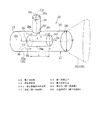
図2に示すように、タービン3と再生器6とは、中空筒状の排気ダクト25によって連結されている。この排気ダクト25は、タービン3寄りの円筒状部25aと、この円筒状部25aの下流端部に接続され、再生器6側に向かって、つまり下流側に向かって末広がりとなった拡径部25bとからなる。この拡径部25bは、上流端部が円形の横断面形状を有し、下流端部が縦長の長方形状を有し、その間の横断面形状が、円形から長方形へと徐々に変化している中空筒状である。ただし、拡径部25bの下流端部も円形の横断面形状とすることができる。
As shown in FIG. 2, the
前記排気ダクト25の円筒状部25aが第1の配管を形成しており、この第1の配管25aに対し、加温用ガスG5を排気ダクト25内に供給する加温用バーナ7からの第2の配管28が接続されている。円筒状部25aの後部の内側には排ガスG4の流れる方向に沿った軸心C1(図3)を有する中空筒状、この例では円筒状の混合促進体38が配置されている。
The
加温用バーナ7には、前述したように、CMM源13(図1)から燃料成分であるCMMが供給されるようになっている。圧縮機1から再生器6へ圧縮ガスG2を供給する圧縮ガス通路24から抽気ガス通路27が分岐しており、この抽気ガス通路27に、加温用バーナ7とその上流側に位置する抽気弁8とが設けられている。抽気ガス通路27における加温用バーナ7よりも下流側が第2の配管28として形成されている。
The
図3および図4を用いて、流体混合器40の詳細を説明する。流体混合器40は、排気ダクト25の一部と、混合促進体38と、第2の配管28の下流部とで構成される。流体混合器40の本体41は、排気ダクト25の一部である第1の配管(円筒状部)25aの下流部と拡径部25bとで形成されている。本体41の上流側端部に第1の流入口43が設けられ、本体41の周壁に、第2の配管28に連なる第2の流入口45が設けられている。さらに、この流体混合器40と、流体混合器40の下流に配置された再生器(熱交換器)6とにより、熱交換システム42が構成されている。
Details of the
図3に示すように、排気ダクト25内を流れる第1の流体である排ガスG4は、第1の流入口43から本体41内に流入し、混合促進体38の外側と内側の両方を流れる。混合促進体38は円筒状部25aと同心状に配置されている。混合促進体38は、この実施形態では、円筒形状であるが、中空の部材であればよく、例えば、多角柱、円錐台、多角錐台でもよく、また、混合促進体38の下流端面が径方向に対して傾斜した形状(後述する図10)であってもよい。
As shown in FIG. 3, the exhaust gas G <b> 4 that is the first fluid flowing in the
第2の配管28は排気ダクト25の円筒状部25aに直交して溶接により接続され、第2の配管28からの第2の流体である加温用ガスG5が、第2の配管28の下流端縁46によって形成された第2の流入口45から、本体41内に流入し、混合促進体38の外周面38aに衝突するようになっている。混合促進体38の外周面38aに衝突した加温用ガスG5は、混合促進体38の外周面38aに沿って案内されながら、排気ダクト25の円筒状部25aの内周面29と混合促進体38の外周面38aとの間を流れる。第1の流体である排ガスG4は第2の流体である加温用ガスG5よりも低温である。
The
混合促進体38は、第2の配管28からの第2の流体である加温用ガスG5が衝突するよう、その外周面38aが第2の流入口45に対向するように位置している。図4から明らかなように、混合促進体38の軸方向において、第2の配管28が形成する第2の流入口45の全体が、側面視で混合促進体38の外周面と混合促進体38の軸方向に重なっている。つまり、第2の流入口45が混合促進体38の上流端縁38bと下流端縁38cとの間に位置している。
The mixing
図3の混合促進体38の外径DOは円筒状部25aの内径DI1の0.35〜0.55倍程度であり、好ましくは、0.4〜0.5倍である。混合促進体38の肉厚は、排ガスG4の流動抵抗を抑制するために、強度が保持される限り、薄くするのがよい。さらに、混合促進体38の外径DOは第2の配管28の内径DI2の0.9〜1.3倍程度であり、好ましくは、1.0〜1.2倍である。混合促進体38の長さLは、第2の配管28の内径DI2の1.2〜3.0倍程度であり、好ましくは、1.5〜2.5倍である。
The outer diameter DO of the mixing
図4に示すように、排気ダクト25の円筒状部25aと第2の配管28とが接続部44によって接続されており、この接続部44における第2の配管28の出口部28aの端縁46が排気ダクト25の円筒状部25aの内周面29とほぼ面一になっている。ただし、第2の配管28の下流端縁46は円筒状部25aの内周面29よりも若干径方向外方に配置してもよい。
As shown in FIG. 4, the
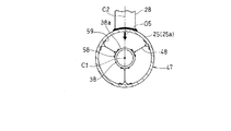
図5に示すように、第2の配管28の軸心C2と排気ダクト25および混合促進体38の軸心C1とは直角に交わっており、第2の配管28からの加温用ガスG5が混合促進体38の頂部とその近傍に衝突するようになっている。混合促進体38は、その径方向に延びる支持部材48を介して排気ダクト25の円筒状部25aに支持されている。支持部材48は、図4に示す混合促進体38の軸心C1方向両端部に設けられ、混合促進体38の外周面に支持部材48の内端部がボルトのような第1締結部材58で固定されており、支持部材48の外端部が排気ダクト25の内周面に、ボルトのような第2締結部材59で連結されている。
As shown in FIG. 5, the axis C2 of the
排気ダクト25に対し支持部材48の一方、この例では、上流側の支持部材48が流れ方向(軸方向)にリジッド(移動不能)に支持され、支持部材48の他方、この例では、下流側の支持部材48が軸方向に移動自在に支持されて、混合促進体38の軸方向の熱膨張を吸収できるようになっている。具体的には、下流側の支持部材48の外端部に軸方向に長い長孔が設けられ、この長孔に第2締結部材59が挿通されることで、混合促進体38が軸方向に移動自在となっている。
One of the
図5に示すように、支持部材48は板材からなり、周方向に3つ配置されており、各支持部材48の径方向の内端部および外端部が二又状に形成されて、混合促進体38の径方向の熱膨張を吸収できるようになっている。混合促進体38の支持構造は、図示の例に限定されず、混合促進体38の熱膨張を吸収できるように構成されていればよく、例えば、排気ダクト25と混合促進体38との間をリンク機構からなる支持部材48のみによって片持ちで支持して、混合促進体38の熱膨張を吸収することもできる。
As shown in FIG. 5, the
上記構成のガスタービンGTの動作について説明する。始動時には、図1の触媒燃焼器2の温度が活性下限温度よりも低いので、加温用バーナ7の点火により再生器6の暖気を行って再生器6を通過する圧縮ガスG2を昇温させ、触媒燃焼器2を触媒反応可能な所定温度になるまで昇温させる。
The operation of the gas turbine GT having the above configuration will be described. At the time of start-up, since the temperature of the
このとき、図3に示すように、流体混合器40では、タービン3からの排ガスG4と、加温用バーナ7からの加温用ガスG5とが混合される。具体的には、排ガスG4が第1の流入口43から流体混合器40の本体41内に流入し、混合促進体38の内側と外側を通って流れるとともに、加温用ガスG5が第2の流入口45から本体41に径方向に流入して混合促進体38の外周面38aに衝突後、混合促進体38の外周面38aと本体41の内周面、つまり排気ダクト25の円筒状部25aの内周面29との間を流れる。
At this time, as shown in FIG. 3, in the
混合促進体38の外周面38aと本体41の内周面29との間を流れる加温用ガスG5は、まず混合促進体38の外側を通って流れる排ガスG4と混合される(一次混合)。加温用ガスG5は混合促進体38の外周面38aに衝突するので、混合促進体38の外周面38aに沿って、本体41の径方向および周方向の全域に案内される。これにより、排ガスG4と加温用ガスG5との混合が促進される。このとき、混合促進体38の内側を通って流れる低温の排ガスG4により、混合促進体38の表面全体が冷却される。
The heating gas G5 flowing between the outer
つぎに、一次混合された排ガスG4と加温用ガスG5との混合ガスが、混合促進体38の下流で、混合促進体38の内部を通って流れる排ガスG4とさらに混合する(二次混合)。このように、2段階で混合することで、排ガスG4と加温用ガスG5との混合が一層促進される。さらに、混合促進体38を通過した混合ガスが本体41の拡径部25bに流入して拡散されるので、混合がなお一層促進される。
Next, the mixed gas of the first-mixed exhaust gas G4 and the heating gas G5 further mixes with the exhaust gas G4 flowing through the inside of the mixing
定格運転に入ると、排ガスG4の温度が上昇して、圧縮機1から供給される圧縮ガスG2が再生器6内で排ガスG4と熱交換されるので、熱交換後の圧縮ガスG2は触媒燃焼器2の作動に十分な高温となる。その結果、抽気弁8が閉弁されて加温用バーナ7の動作が停止する。これにより、図3に示す流体混合器40では、排ガスG4のみが流れ、加温用ガスG5は導入されない。すなわち、排ガスG4のみが混合促進体38の内側と外側を通って流れている状態である。このとき、混合促進体38は排ガスG4の流れる方向に沿った軸心C1を有する形状であるから、排ガスG4が混合促進体38から受ける抵抗は小さくて済む。したがって、最も稼働時間の長い定格運転時に、排ガスG4の圧力損失が効果的に抑制される。
When the rated operation is started, the temperature of the exhaust gas G4 rises, and the compressed gas G2 supplied from the
上記構成において、図3に示すように、排ガスG4の流れる方向に沿った軸心C1を有する混合促進体38が本体41の内側に配置され、排ガスG4がこの混合促進体38の軸心C1方向に沿って混合促進体38の外側と内側を流れるから、排ガスG4の圧力損失を抑制することができる。また、加温用ガスG5が混合促進体38の外周面38aに向かって導入されるので、加温用ガスG5は混合促進体38の外周面38aに衝突して本体41の径方向および周方向に回りこむことで、混合促進体38の外側において排ガスG4と加温用ガスG5とが十分に混合される。加温用ガスG5は、混合促進体38の外側を流れる排ガスG4と混合された後、混合促進体38の内側を流れる排ガスG4と再度混合されることで、排ガスG4と加温用ガスG5との混合が促進される。さらに、本体41の内側に混合促進体38を配置し、この混合促進体38に向かって加温用ガスG5を導入する第2の流入口45を配置するだけであるから、構造が簡単である。
In the above configuration, as shown in FIG. 3, the mixing
また、混合促進体38が本体41とほぼ同心に配置されているので、第2の流入口45の本体41周方向の設置位置に関わらず、第2の流入口45と混合促進体38の距離が一定となり、第2の流入口45と混合促進体38の位置関係に正確性が要求されなくなる結果、製造が容易になる。
Further, since the mixing
また、第2の配管28は排気ダクト25にほぼ直交して接続されているので、加温用ガスG5が混合促進体38の外周面38aに直交する向きに衝突するから、加温用ガスG5が混合促進体38の外周面38aに案内されて排気ダクト25の径方向および周方向の全域に回り込み、その結果、排ガスG4と加温用ガスG5との混合が一層促進される。
Further, since the
図4に示すように、排気ダクト25と第2の配管28との接続部44における第2の配管28の端縁46が、排気ダクト25の内周面29と面一であるから、第2の配管28により、排気ダクト25を流れる排ガスG4の流れが阻害されることがなくなり、排ガスG4の圧力損失が一層抑制される。
As shown in FIG. 4, since the
また、排ガスG4は加温用ガスG5よりも低温であるから、排ガスG4により、高温の加温用ガスG5と接する混合促進体38の表面全体が冷却されるから、混合促進体38の過熱を防ぐための構造を別途設ける必要がなく、構造が一層簡単になる。
Further, since the exhaust gas G4 has a lower temperature than the heating gas G5, the exhaust gas G4 cools the entire surface of the mixing
図3に示すように、本体41における下流部が、下流に向かって通路面積が増大する拡径部25bにより形成されているので、拡径部25bにより排ガスG4と加温用ガスG5の混合ガスが拡散され、混合が一層促進される。
As shown in FIG. 3, since the downstream part in the
図2に示すように、流体混合器40が、熱交換器である再生器6の上流側に配置されているので、流体混合器40により排ガスG4と加温用ガスG5が十分に混合された後、再生器6に導かれるから、混合流体の流れを直交する断面での温度分布が均一化される結果、熱交換効率が向上する。
As shown in FIG. 2, since the
上記実施形態の流体混合器40について、混合状態を確認するために、コンピュータ解析を行った。また、比較例として、上記実施形態の流体混合器40において混合促進体38を有さない構造についても同様の解析を行った。
Computer analysis was performed on the
図6は上記実施形態の流体混合器40を用いて排ガスG4と加温用ガスG5とを混合させた際の軸方向における温度分布、図7は図6のVII-VII線断面上、つまり流体混合器40の出口(再生器6の入口)箇所における径方向の温度分布を示し、図8および9は比較例の各温度分布を示す。以下の図において、(1)〜(21)は高温から低温にかけての領域を表す。図6および図8において、(1)〜(9)の同一番号は同一温度領域を示す。同様に、図7および図9において、(10)〜(21)の同一番号は同一温度領域を示す。図6に示すように、上記実施形態の流体混合器40では、高温の加温用ガスG5が拡径部25bの中心部から下部にかけて広がっており、その結果、図7に示すように、流体混合器40の出口箇所において、温度分布が均一化されており、適度に混合されていることがわかる。一方、比較例の流体混合器では、図8に示すように、高温の加温用ガスG5が拡径部25bの下部に集中して流れ込んでおり、その結果、図9に示すように、流体混合器40の出口箇所において、温度分布が偏っており、十分に混合されていない。
6 is a temperature distribution in the axial direction when the exhaust gas G4 and the heating gas G5 are mixed using the
図10は第2実施形態に係る流体混合器40Aを示す概略構成図である。第2実施形態の流体混合器40Aと第1実施形態の流体混合器40との違いは、混合促進体38Aの下流端面62が下流に進むにつれて上方に傾いた傾斜面である点のみで、その他の構造は、第1実施形態と同じである。つまり、混合促進体38における第2の配管28に対向する部分(上部)とは反対側の部分(下部)の下流端部が、切り欠かれて傾斜している。この例では、下流端面62の径方向に対する傾斜角θが45°となっているが、この傾斜角θは20〜60°程度とすることができ、30〜50°程度がより好ましい。第2の流入口45は、混合促進体38Aの上流端縁38Aaと、混合促進体38Aにおける第2の流入口45と対向する部分(図10の上部)の下流端縁38Abとの間に位置している。
FIG. 10 is a schematic configuration diagram showing a
第2実施形態の流体混合器40Aにおいても、第1実施形態の流体混合器40と同様に、コンピュータ解析による検証を行った。その結果を図11および12に示す。図11から分かるように、第2実施形態の流体混合器40Aでは、より多くの高温の加温用ガスG5が拡径部25bの中心部近くを流れるので、図12から分かるように、第1実施形態の流体混合器40よりもさらに温度分布が均一化されている。
In the
第1および第2実施形態では、本体41の上流部を形成する円筒状部25aの下流部は、円筒状であったが、下流に向かって若干拡大する小さなテーパ比を有する拡大管であってもよい。また、本体41の拡径部25bのテーパ比が小さい場合、拡径部25bの内側に混合促進体38を配置してもよい。さらに、拡径部25bを省略して、流体混合器40の本体41の全体を円筒状としてもよい。また、第2の流入口45を複数設け、各流入口45から異なる流体を本体41に流入させてもよい。
In the first and second embodiments, the downstream portion of the
以上のとおり、図面を参照しながら本発明の好適な実施形態を説明したが、本発明の趣旨を逸脱しない範囲内で、種々の追加、変更または削除が可能であり、そのようなものも本発明の範囲内に含まれる。したがって、そのようなものも本発明の範囲内に含まれる。 As described above, the preferred embodiment of the present invention has been described with reference to the drawings, but various additions, modifications, or deletions can be made without departing from the spirit of the present invention. Included within the scope of the invention. Therefore, such a thing is also included in the scope of the present invention.
6 再生器(熱交換器)
25 排気ダクト
28 第2の配管
29 本体の内周面
38、38A 混合促進体
38a 混合促進体の外周面
40、40A 流体混合器
41 本体(第1の配管)
42 熱交換システム
43 第1の流入口
44 接続部
45 第2の流入口
46 第2の配管の端縁
C1 軸心
G4 排ガス(第1の流体)
G5 加温用ガス(第2の流体)
6 Regenerator (heat exchanger)
25
42
G5 Gas for heating (second fluid)
Claims (6)
前記本体の上流側端部に設けられて前記第1の流体を流入させる第1の流入口と、
前記本体の内側に配置され、前記第1の流体の流れる方向に沿った軸心を有し、両端が開口した中空筒状の混合促進体と、
前記本体の周壁に設けられて前記混合促進体の外周面に向かって前記第2の流体を流入させる第2の流入口とを備え、
前記混合促進体が前記本体とほぼ同心に配置され、
前記第1の流入口から前記本体に流れ込んだ前記第1の流体が、前記混合促進体の内側と外側を通って流れ、
前記混合促進体の外側を通って流れる前記第1の流体が前記第2の流入口から前記本体に流れ込んだ前記第2の流体と一次混合され、
一次混合された前記第1および第2の流体の混合流体が、前記混合促進体の下流で、前記混合促進体の内側を通って流れる前記第1の流体と二次混合される流体混合器。 A hollow cylindrical body that mixes the first and second fluids on the inside;
A first inflow port provided at an upstream end of the main body and into which the first fluid flows;
A hollow cylindrical mixing accelerator that is disposed inside the main body, has an axial center along the direction in which the first fluid flows, and is open at both ends;
A second inflow port provided on the peripheral wall of the main body to allow the second fluid to flow toward the outer peripheral surface of the mixing accelerator;
The mixing accelerator is disposed substantially concentrically with the body;
The first fluid flowing into the main body from the first inlet flows through the inside and outside of the mixing accelerator;
The first fluid flowing through the outside of the mixing accelerator is primarily mixed with the second fluid flowing into the body from the second inlet;
A fluid mixer in which a mixed fluid of the first and second fluids that have undergone primary mixing is secondarily mixed with the first fluid that flows through the inside of the mixing accelerator downstream of the mixing accelerator .
Priority Applications (7)
| Application Number | Priority Date | Filing Date | Title |
|---|---|---|---|
| JP2011223820A JP5719745B2 (en) | 2011-10-11 | 2011-10-11 | Fluid mixer and heat exchange system using the same |
| CN201280049513.0A CN103857463B (en) | 2011-10-11 | 2012-08-23 | Flow mixer and use its heat-exchange system |
| AU2012321964A AU2012321964B2 (en) | 2011-10-11 | 2012-08-23 | Fluid mixer and heat exchange system using same |
| PCT/JP2012/071279 WO2013054595A1 (en) | 2011-10-11 | 2012-08-23 | Fluid mixer and heat exchange system using same |
| RU2014118531/02A RU2590020C2 (en) | 2011-10-11 | 2012-08-23 | Fluid mixer and heat exchange system using same |
| UAA201404938A UA107906C2 (en) | 2011-10-11 | 2012-08-23 | Mixer of fluids and heat exchange system, which uses it |
| US14/245,158 US10092886B2 (en) | 2011-10-11 | 2014-04-04 | Fluid mixer and heat exchange system using same |
Applications Claiming Priority (1)
| Application Number | Priority Date | Filing Date | Title |
|---|---|---|---|
| JP2011223820A JP5719745B2 (en) | 2011-10-11 | 2011-10-11 | Fluid mixer and heat exchange system using the same |
Publications (3)
| Publication Number | Publication Date |
|---|---|
| JP2013081905A JP2013081905A (en) | 2013-05-09 |
| JP2013081905A5 JP2013081905A5 (en) | 2014-08-21 |
| JP5719745B2 true JP5719745B2 (en) | 2015-05-20 |
Family
ID=48081655
Family Applications (1)
| Application Number | Title | Priority Date | Filing Date |
|---|---|---|---|
| JP2011223820A Active JP5719745B2 (en) | 2011-10-11 | 2011-10-11 | Fluid mixer and heat exchange system using the same |
Country Status (7)
| Country | Link |
|---|---|
| US (1) | US10092886B2 (en) |
| JP (1) | JP5719745B2 (en) |
| CN (1) | CN103857463B (en) |
| AU (1) | AU2012321964B2 (en) |
| RU (1) | RU2590020C2 (en) |
| UA (1) | UA107906C2 (en) |
| WO (1) | WO2013054595A1 (en) |
Families Citing this family (17)
| Publication number | Priority date | Publication date | Assignee | Title |
|---|---|---|---|---|
| JP5719745B2 (en) * | 2011-10-11 | 2015-05-20 | 川崎重工業株式会社 | Fluid mixer and heat exchange system using the same |
| JP6244159B2 (en) * | 2013-10-11 | 2017-12-06 | 川崎重工業株式会社 | Gas mixer |
| US20150124552A1 (en) * | 2013-11-04 | 2015-05-07 | Yang Shi | System and method for mixing a gas and a liquid |
| CN106268385A (en) * | 2015-06-24 | 2017-01-04 | 贵州航空发动机研究所 | A kind of high-temperature fuel gas mixing device |
| EP3181866B1 (en) * | 2015-12-16 | 2018-07-04 | Airbus Operations, S.L. | Gas turbine engine for an aircraft |
| RU2666423C1 (en) * | 2017-11-30 | 2018-09-07 | Акционерное Общество "Российский Концерн По Производству Электрической И Тепловой Энергии На Атомных Станциях" (Ао "Концерн Росэнергоатом") | Device for mixing and heating gas media |
| US11857933B2 (en) * | 2018-03-09 | 2024-01-02 | Produced Water Absorbents Inc. | Systems, apparatuses, and methods for mixing fluids using a conical flow member |
| US10458446B1 (en) * | 2018-11-29 | 2019-10-29 | Vortex Pipe Systems LLC | Material flow amplifier |
| US11221028B1 (en) | 2018-11-29 | 2022-01-11 | Vortex Pipe Systems LLC | Cyclonic flow-inducing pump |
| ES2713123B2 (en) * | 2019-02-19 | 2019-11-06 | Univ Madrid Politecnica | THERMAL SYSTEM WITH COMPRESSOR AND GAS EXPANSION TURBINE IN CLOSED CIRCUIT, WITH HEAT CONTRIBUTION FROM OUTDOOR SOURCE, AND INTERNAL RECOVERY OF HEAT AND MECHANICAL ENERGY, FOR GENERATION OF ELECTRICITY AND PROCEDURE |
| KR102086440B1 (en) * | 2019-05-31 | 2020-03-09 | 주식회사 이엠코 | Apparatus for treating exhaust gas of thermal plant |
| US11002301B1 (en) | 2020-09-15 | 2021-05-11 | Vortex Pipe Systems LLC | Material flow modifier and apparatus comprising same |
| CN112934014A (en) * | 2021-01-30 | 2021-06-11 | 河南省奥瑞环保科技有限公司 | Multi-gas dynamic distribution control device and system |
| CN114225732B (en) * | 2021-12-22 | 2024-07-16 | 哈尔滨名诺环保科技有限公司 | Gas-gas static mixer capable of reducing resistance and improving effect |
| US11378110B1 (en) | 2022-01-05 | 2022-07-05 | Vortex Pipe Systems LLC | Flexible fluid flow modifying device |
| CN115790247B (en) * | 2023-01-06 | 2023-04-21 | 中国核动力研究设计院 | Flow equalizing component and heat exchange device |
| US11739774B1 (en) | 2023-01-30 | 2023-08-29 | Vortex Pipe Systems LLC | Flow modifying device with performance enhancing vane structure |
Family Cites Families (35)
| Publication number | Priority date | Publication date | Assignee | Title |
|---|---|---|---|---|
| US1454196A (en) * | 1921-07-16 | 1923-05-08 | Trood Samuel | Device for producing and utilizing combustible mixture |
| US1466006A (en) * | 1922-09-14 | 1923-08-28 | Trood Samuel | Apparatus for producing and utilizing combustible mixture |
| US1672209A (en) * | 1923-09-24 | 1928-06-05 | Fairbanks Morse & Co | Priming device |
| US1678225A (en) * | 1926-10-28 | 1928-07-24 | Jerry W Kincade | Agitator for chemically purifying oil |
| US1903429A (en) * | 1929-08-08 | 1933-04-11 | Paul W Merchant | Mixing device |
| US2831754A (en) * | 1954-05-10 | 1958-04-22 | Jones & Laughlin Steel Corp | Solvent extraction process |
| US3304564A (en) * | 1965-10-04 | 1967-02-21 | Green Jack | Apparatus for cleaning a body of liquid and maintaining its level |
| SU394073A1 (en) * | 1968-08-05 | 1973-08-22 | MIXER | |
| DE1904014C3 (en) * | 1969-01-28 | 1974-06-20 | Noll Maschinenfabrik Gmbh, 4950 Minden | Device for continuously combining beverage components in an adjustable proportion |
| JPS5372273U (en) * | 1976-11-18 | 1978-06-16 | ||
| US4296779A (en) * | 1979-10-09 | 1981-10-27 | Smick Ronald H | Turbulator with ganged strips |
| SU882571A1 (en) * | 1980-02-22 | 1981-11-23 | Предприятие П/Я Г-4696 | Gas air mixer |
| JPS6046117U (en) * | 1983-09-09 | 1985-04-01 | 三菱重工業株式会社 | fluid mixing device |
| JPH0660640B2 (en) * | 1985-09-09 | 1994-08-10 | 清之 堀井 | Device for generating a spiral fluid flow in a pipeline |
| CH676628A5 (en) * | 1988-06-16 | 1991-02-15 | Ceramic Technology Foundation | Dual liquid mixing device - has low pressure chamber for low pressure fluid between venturi for high pressure fluid and discharge valve |
| CA1295585C (en) * | 1988-08-25 | 1992-02-11 | Chemonics Industries, Inc. | Apparatus for applying fire-fighting chemicals |
| SU1607916A1 (en) * | 1989-01-09 | 1990-11-23 | Всесоюзный Теплотехнический Научно-Исследовательский Институт Им.Ф.Э.Дзержинского | Mixer of streams of fluid substances |
| JPH0448921A (en) * | 1990-06-18 | 1992-02-18 | Inax Corp | Ejector |
| SE500071C2 (en) * | 1992-06-25 | 1994-04-11 | Vattenfall Utveckling Ab | Device for mixing two fluids, in particular liquids of different temperature |
| RU2056920C1 (en) * | 1993-12-20 | 1996-03-27 | Товарищество с ограниченной ответственностью "Камен" | Spray-type mixer |
| US5743637A (en) * | 1995-11-09 | 1998-04-28 | Chem Financial, Inc. | Venturi mixing valve for use in mixing liquids |
| JP2002136855A (en) | 2000-11-02 | 2002-05-14 | Mitsubishi Heavy Ind Ltd | Fluid mixer |
| US6453926B1 (en) * | 2001-04-10 | 2002-09-24 | Gary A. Baker | Method and apparatus for injecting a chemical into a fluid stream |
| JP2003126667A (en) * | 2001-10-22 | 2003-05-07 | Mitsuru Kitahara | Air mixing and feeding device |
| US7029165B2 (en) * | 2001-10-26 | 2006-04-18 | Allen Thomas E | Automatically adjusting annular jet mixer |
| CN2629817Y (en) * | 2003-06-19 | 2004-08-04 | 中国石化上海石油化工股份有限公司 | Gas-liquid mixing jet device |
| FR2858248B1 (en) * | 2003-07-29 | 2005-10-28 | Jeumont Sa | DEVICE FOR MIXING TWO FLUIDS AND USE FOR COOLING A VERY HIGH TEMPERATURE FLUID |
| US7416404B2 (en) * | 2005-04-18 | 2008-08-26 | General Electric Company | Feed injector for gasification and related method |
| JP4989062B2 (en) * | 2005-04-28 | 2012-08-01 | バブコック日立株式会社 | Fluid mixing device |
| US20070144158A1 (en) * | 2005-12-22 | 2007-06-28 | Girard James W | Exhaust dispersion device |
| JP2008049306A (en) | 2006-08-28 | 2008-03-06 | Hitachi Ltd | Apparatus for mixing gas |
| JP2010149062A (en) * | 2008-12-25 | 2010-07-08 | Fujifilm Corp | Apparatus and method of mixing fluid |
| US20130176814A1 (en) * | 2010-09-28 | 2013-07-11 | Dow Global Technologies Llc | Reactive flow static mixer with cross flow obstructions |
| JP5719745B2 (en) * | 2011-10-11 | 2015-05-20 | 川崎重工業株式会社 | Fluid mixer and heat exchange system using the same |
| US9885318B2 (en) * | 2015-01-07 | 2018-02-06 | Jason E Green | Mixing assembly |
-
2011
- 2011-10-11 JP JP2011223820A patent/JP5719745B2/en active Active
-
2012
- 2012-08-23 RU RU2014118531/02A patent/RU2590020C2/en not_active IP Right Cessation
- 2012-08-23 UA UAA201404938A patent/UA107906C2/en unknown
- 2012-08-23 AU AU2012321964A patent/AU2012321964B2/en not_active Ceased
- 2012-08-23 CN CN201280049513.0A patent/CN103857463B/en not_active Expired - Fee Related
- 2012-08-23 WO PCT/JP2012/071279 patent/WO2013054595A1/en active Application Filing
-
2014
- 2014-04-04 US US14/245,158 patent/US10092886B2/en active Active
Also Published As
| Publication number | Publication date |
|---|---|
| UA107906C2 (en) | 2015-02-25 |
| CN103857463A (en) | 2014-06-11 |
| JP2013081905A (en) | 2013-05-09 |
| AU2012321964B2 (en) | 2015-07-30 |
| AU2012321964A1 (en) | 2014-05-01 |
| RU2014118531A (en) | 2015-11-20 |
| RU2590020C2 (en) | 2016-07-10 |
| US10092886B2 (en) | 2018-10-09 |
| CN103857463B (en) | 2016-01-27 |
| US20140219048A1 (en) | 2014-08-07 |
| WO2013054595A1 (en) | 2013-04-18 |
Similar Documents
| Publication | Publication Date | Title |
|---|---|---|
| JP5719745B2 (en) | Fluid mixer and heat exchange system using the same | |
| EP2236935A2 (en) | Method And System For Reducing The Level Of Emissions Generated By A System | |
| RU2627759C2 (en) | Consequent burning with the dilution gas mixer | |
| JP6266290B2 (en) | Fuel nozzle for gas turbine engine combustor | |
| EP2463499A1 (en) | Submerged combustion vaporizer with low NOx | |
| CN102472493B (en) | Gas turbine combustor and gas turbine | |
| JP6172523B2 (en) | Axial piston engine and method of operating axial piston engine | |
| JP2014181902A (en) | System for providing fuel to combustor | |
| CN101713541A (en) | Premixed direct injection nozzle | |
| JP2010281324A (en) | Methods relating to turbine engine control and operation | |
| JP2010019247A (en) | Lean fuel suction gas turbine | |
| JP2016017740A (en) | Two-stage combustor arrangement with mixer | |
| JP4961415B2 (en) | Gas turbine combustor | |
| JP2017110646A (en) | Power plant with steam generation via combustor gas extraction | |
| JP2018112389A (en) | Automatic heat sensitive valve passively controlling flow of fuel to shaft upper fuel stage of gas turbine | |
| BR112020022559A2 (en) | system and method of improving combustion stability in a gas turbine | |
| JP6244159B2 (en) | Gas mixer | |
| JP6106406B2 (en) | Combustor and method for distributing fuel in the combustor | |
| WO2013099582A1 (en) | Catalytic combustor in gas turbine engine | |
| US20140157788A1 (en) | Fuel nozzle for gas turbine | |
| RU2171903C1 (en) | Modular mobile gas-turbine power-and-heat generation plant and shell boiler for plant | |
| CN102057221B (en) | Gas flame stabilization method and apparatus | |
| JP2014202475A (en) | Catalytic combustion air heating system | |
| JP2013133778A (en) | Gas turbine engine including heat exchanger | |
| KR20180003202A (en) | NOx removal apparatus for a gas turbine |
Legal Events
| Date | Code | Title | Description |
|---|---|---|---|
| A521 | Request for written amendment filed |
Free format text: JAPANESE INTERMEDIATE CODE: A523 Effective date: 20140709 |
|
| A621 | Written request for application examination |
Free format text: JAPANESE INTERMEDIATE CODE: A621 Effective date: 20140709 |
|
| A131 | Notification of reasons for refusal |
Free format text: JAPANESE INTERMEDIATE CODE: A131 Effective date: 20141104 |
|
| A521 | Request for written amendment filed |
Free format text: JAPANESE INTERMEDIATE CODE: A523 Effective date: 20141210 |
|
| TRDD | Decision of grant or rejection written | ||
| A01 | Written decision to grant a patent or to grant a registration (utility model) |
Free format text: JAPANESE INTERMEDIATE CODE: A01 Effective date: 20150317 |
|
| A61 | First payment of annual fees (during grant procedure) |
Free format text: JAPANESE INTERMEDIATE CODE: A61 Effective date: 20150323 |
|
| R150 | Certificate of patent or registration of utility model |
Ref document number: 5719745 Country of ref document: JP Free format text: JAPANESE INTERMEDIATE CODE: R150 |