JP5710768B2 - Synchronizing images across multiple displays - Google Patents
Synchronizing images across multiple displays Download PDFInfo
- Publication number
- JP5710768B2 JP5710768B2 JP2013531777A JP2013531777A JP5710768B2 JP 5710768 B2 JP5710768 B2 JP 5710768B2 JP 2013531777 A JP2013531777 A JP 2013531777A JP 2013531777 A JP2013531777 A JP 2013531777A JP 5710768 B2 JP5710768 B2 JP 5710768B2
- Authority
- JP
- Japan
- Prior art keywords
- display
- image
- state
- sub
- blanking
- Prior art date
- Legal status (The legal status is an assumption and is not a legal conclusion. Google has not performed a legal analysis and makes no representation as to the accuracy of the status listed.)
- Expired - Fee Related
Links
- 238000000034 method Methods 0.000 claims description 81
- 238000004891 communication Methods 0.000 claims description 13
- 238000005259 measurement Methods 0.000 claims description 7
- 239000000872 buffer Substances 0.000 description 45
- 238000012545 processing Methods 0.000 description 22
- 238000010586 diagram Methods 0.000 description 11
- 230000003111 delayed effect Effects 0.000 description 5
- 239000013316 polymer of intrinsic microporosity Substances 0.000 description 4
- 230000001360 synchronised effect Effects 0.000 description 4
- 239000013078 crystal Substances 0.000 description 3
- 230000004044 response Effects 0.000 description 3
- 238000003491 array Methods 0.000 description 2
- 238000013500 data storage Methods 0.000 description 2
- 230000001934 delay Effects 0.000 description 2
- 230000000694 effects Effects 0.000 description 2
- 239000004973 liquid crystal related substance Substances 0.000 description 2
- 230000003287 optical effect Effects 0.000 description 2
- 230000001413 cellular effect Effects 0.000 description 1
- 238000004590 computer program Methods 0.000 description 1
- 230000007774 longterm Effects 0.000 description 1
- 239000003550 marker Substances 0.000 description 1
- 238000012544 monitoring process Methods 0.000 description 1
- 239000005022 packaging material Substances 0.000 description 1
- 238000009877 rendering Methods 0.000 description 1
- 229910052710 silicon Inorganic materials 0.000 description 1
- 230000000007 visual effect Effects 0.000 description 1
Images


Classifications
-
- G—PHYSICS
- G06—COMPUTING; CALCULATING OR COUNTING
- G06F—ELECTRIC DIGITAL DATA PROCESSING
- G06F3/00—Input arrangements for transferring data to be processed into a form capable of being handled by the computer; Output arrangements for transferring data from processing unit to output unit, e.g. interface arrangements
- G06F3/14—Digital output to display device ; Cooperation and interconnection of the display device with other functional units
- G06F3/1423—Digital output to display device ; Cooperation and interconnection of the display device with other functional units controlling a plurality of local displays, e.g. CRT and flat panel display
- G06F3/1446—Digital output to display device ; Cooperation and interconnection of the display device with other functional units controlling a plurality of local displays, e.g. CRT and flat panel display display composed of modules, e.g. video walls
-
- G—PHYSICS
- G06—COMPUTING; CALCULATING OR COUNTING
- G06F—ELECTRIC DIGITAL DATA PROCESSING
- G06F3/00—Input arrangements for transferring data to be processed into a form capable of being handled by the computer; Output arrangements for transferring data from processing unit to output unit, e.g. interface arrangements
- G06F3/14—Digital output to display device ; Cooperation and interconnection of the display device with other functional units
- G06F3/1423—Digital output to display device ; Cooperation and interconnection of the display device with other functional units controlling a plurality of local displays, e.g. CRT and flat panel display
- G06F3/1438—Digital output to display device ; Cooperation and interconnection of the display device with other functional units controlling a plurality of local displays, e.g. CRT and flat panel display using more than one graphics controller
-
- G—PHYSICS
- G09—EDUCATION; CRYPTOGRAPHY; DISPLAY; ADVERTISING; SEALS
- G09G—ARRANGEMENTS OR CIRCUITS FOR CONTROL OF INDICATING DEVICES USING STATIC MEANS TO PRESENT VARIABLE INFORMATION
- G09G5/00—Control arrangements or circuits for visual indicators common to cathode-ray tube indicators and other visual indicators
- G09G5/12—Synchronisation between the display unit and other units, e.g. other display units, video-disc players
-
- G—PHYSICS
- G09—EDUCATION; CRYPTOGRAPHY; DISPLAY; ADVERTISING; SEALS
- G09G—ARRANGEMENTS OR CIRCUITS FOR CONTROL OF INDICATING DEVICES USING STATIC MEANS TO PRESENT VARIABLE INFORMATION
- G09G2310/00—Command of the display device
- G09G2310/08—Details of timing specific for flat panels, other than clock recovery
Description
本開示は、複数のディスプレイユニットに分けて表示される1つまたは複数の画像を制御することに関する。 The present disclosure relates to controlling one or more images displayed separately on a plurality of display units.
一般に、1つまたは複数の画像を表示するように構成されるディスプレイユニットは、スマートディスプレイおよびダムディスプレイという2つのカテゴリに分類され得る。ダムディスプレイはホストコントローラからの画像データの他にタイミング情報および同期情報を受け取るものであるが、スマートディスプレイはこのようなタイミング情報および同期情報を必要としない。いくつかの例では、スマートディスプレイは、1つまたは複数のフレームバッファを含み得る。いくつかの例では、スマートディスプレイがまた、あるいは代わりに、画像を表示するように動作するためにスマートディスプレイによって使用される内部のクロック基準を含み得る。 In general, display units configured to display one or more images can be divided into two categories: smart displays and dumb displays. The dumb display receives timing information and synchronization information in addition to image data from the host controller, but the smart display does not require such timing information and synchronization information. In some examples, the smart display may include one or more frame buffers. In some examples, the smart display may also or alternatively include an internal clock reference used by the smart display to operate to display an image.
本開示は、複数のディスプレイデバイスにわたって、すなわちこれらディスプレイデバイス間で分かれて表示された1つまたは複数の画像の表示を制御するための複数の技法を意図する。これら技法によれば、いくつかの例で、ホストコントローラが、画像の第1の部分を表示するための第1のディスプレイの状態を示す第1のディスプレイ状態を受け取ることができる。ホストコントローラはまた、画像の第2の部分を表示するための第2のディスプレイの状態を示す第2のディスプレイ状態を受け取ることができる。いくつかの例では、第1のディスプレイ状態および第2のディスプレイ状態が、水平同期(hsync)信号または垂直同期(vsync)信号と呼ばれ得る。ホストコントローラは、第1のディスプレイ状態と第2のディスプレイ状態とを比較して、画像の第1の部分と第2の部分とをそれぞれ表示するための第1のディスプレイと第2のディスプレイの状態の差を示すオフセットを求めることができる。例えば、このオフセットは、第1のディスプレイによって表示される第1の画像部分の副部分(例えば線)の数と、第2のディスプレイによって表示される第2の画像部分の副部分の数との差を示すことができる。求められたオフセットに応じ、ホストコントローラは第1のディスプレイと第2のディスプレイの少なくとも1つにディスプレイ調整を伝えることができる。このディスプレイ調整は、画像の第1の部分または第2の部分の表示を調整することを第1のディスプレイまたは第2のディスプレイに行わせることができる。例えば、ディスプレイ調整は、画像の第1の部分および第2の部分の1つまたは複数の少なくとも1つの副部分(例えば線)の表示を、少なくとも1つの副部分の表示時間を調整することなどによって調整することを第1のディスプレイまたは第2のディスプレイに行わせることができる。 The present disclosure contemplates a plurality of techniques for controlling the display of one or more images displayed across a plurality of display devices, ie, between the display devices. According to these techniques, in some examples, the host controller can receive a first display state that indicates the state of the first display for displaying the first portion of the image. The host controller may also receive a second display state that indicates the state of the second display for displaying the second portion of the image. In some examples, the first display state and the second display state may be referred to as a horizontal sync (hsync) signal or a vertical sync (vsync) signal. The host controller compares the first display state and the second display state, and the first display state and the second display state for displaying the first part and the second part of the image, respectively. An offset indicating the difference between the two can be obtained. For example, the offset is the number of sub-portions (eg, lines) of the first image portion displayed by the first display and the number of sub-portions of the second image portion displayed by the second display. A difference can be shown. Depending on the determined offset, the host controller can communicate the display adjustment to at least one of the first display and the second display. This display adjustment can cause the first display or the second display to adjust the display of the first portion or the second portion of the image. For example, the display adjustment may include displaying one or more at least one sub-portion (eg, line) of the first and second portions of the image, adjusting the display time of at least one sub-portion, etc. Adjustments can be made to the first display or the second display.
一例によれば、方法が本明細書で説明される。この方法は、第1のディスプレイによる画像の第1の部分の表示の状態を示す第1のディスプレイ状態を第1のディスプレイから受け取ることを含む。この方法はさらに、第2のディスプレイによる画像の第2の部分の表示の状態を示す第2のディスプレイ状態を第2のディスプレイから受け取ることを含む。この方法はさらに、第1のディスプレイによる画像の第1の部分の表示の状態と第2のディスプレイによる画像の第2の部分の表示の状態との差を求めることを含む。この方法はさらに、求められた差に基づいて第1のディスプレイによる画像の第1の部分の表示、および第2のディスプレイによる画像の第2の部分の表示の少なくとも1つを調整することを含む。 According to an example, a method is described herein. The method includes receiving from the first display a first display state that indicates a state of display of the first portion of the image by the first display. The method further includes receiving from the second display a second display state indicative of a state of display of the second portion of the image by the second display. The method further includes determining a difference between a display state of the first portion of the image on the first display and a display state of the second portion of the image on the second display. The method further includes adjusting at least one of the display of the first portion of the image by the first display and the display of the second portion of the image by the second display based on the determined difference. .
別の例によれば、デバイスが本明細書で説明される。このデバイスは、第1のディスプレイによる画像の第1の部分の表示の状態を示す第1のディスプレイ状態と第2のディスプレイによる画像の第2の部分の表示の状態を示す第2のディスプレイ状態とを受け取るように構成されるディスプレイ状態モジュールを含む。このデバイスはさらに、第1のディスプレイ状態と第2のディスプレイ状態とに基づいて第1のディスプレイによる画像の第1の部分の表示の状態と第2のディスプレイによる画像の第2の部分の表示の状態との差を求めるように構成されるオフセット測定モジュールを含む。このデバイスはさらに、第1のディスプレイによる画像の第1の部分の表示、および第2のディスプレイによる画像の第2の部分の表示の少なくとも1つを調整するように構成されるディスプレイ調整を第1のディスプレイと第2のディスプレイの少なくとも1つに伝えるように構成されるディスプレイ調整モジュールを含む。 According to another example, a device is described herein. The device includes a first display state indicating a display state of a first portion of an image on the first display, and a second display state indicating a display state of a second portion of the image on the second display. Including a display status module configured to receive The device further includes the display state of the first portion of the image by the first display and the display of the second portion of the image by the second display based on the first display state and the second display state. An offset measurement module configured to determine a difference from the state is included. The device further includes a first display adjustment configured to adjust at least one of the display of the first portion of the image by the first display and the display of the second portion of the image by the second display. A display adjustment module configured to communicate to at least one of the second display and the second display.
別の例によれば、デバイスが本明細書で説明される。このデバイスは、第1のディスプレイによる画像の第1の部分の表示の状態を第1のディスプレイから受け取るための手段を含む。このデバイスはさらに、第2のディスプレイによる画像の第2の部分の表示の状態を示す第2のディスプレイ状態を第2のディスプレイから受け取るための手段を含む。このデバイスはさらに、少なくとも1つの画像の第1の部分を出力するための第1のディスプレイの状態と少なくとも1つの画像の第2の部分を出力するための第2のディスプレイの状態との差を求めるための手段を含む。このデバイスはさらに、求められた差に基づいて第1のディスプレイによる画像の第1の部分の表示、および第2のディスプレイによる画像の第2の部分の表示の少なくとも1つを調整するための手段を含む。 According to another example, a device is described herein. The device includes means for receiving from the first display a state of display of the first portion of the image by the first display. The device further includes means for receiving from the second display a second display state indicative of a state of display of the second portion of the image by the second display. The device further provides a difference between a state of the first display for outputting the first portion of the at least one image and a state of the second display for outputting the second portion of the at least one image. Includes means for seeking. The device further includes means for adjusting at least one of the display of the first portion of the image by the first display and the display of the second portion of the image by the second display based on the determined difference. including.
別の例によれば、複数の命令を備えるコンピュータ可読記憶媒体が本明細書で説明される。これら命令は、コンピューティングデバイスによって実行されることに伴い、第1のディスプレイによる画像の第1の部分の表示の状態を示す第1のディスプレイ状態を第1のディスプレイから受け取ることをコンピューティングデバイスに行わせるように構成される。これら命令はさらに、第2のディスプレイによる画像の第2の部分の表示の状態を示す第2のディスプレイ状態を第2のディスプレイから受け取ることをコンピューティングデバイスに行わせるように構成される。これら命令はさらに、第1のディスプレイによる画像の第1の部分の表示の状態と第2のディスプレイによる画像の第2の部分の表示の状態との差を求めることをコンピューティングデバイスに行わせるように構成される。これら命令はさらに、求められた差に基づいて、第1のディスプレイによる画像の第1の部分の表示、および第2のディスプレイによる画像の第2の部分の表示の少なくとも1つを調整することをコンピューティングデバイスに行わせるように構成される。 According to another example, a computer-readable storage medium comprising a plurality of instructions is described herein. These instructions, when executed by the computing device, cause the computing device to receive a first display state from the first display that indicates a state of display of the first portion of the image by the first display. Configured to do. The instructions are further configured to cause the computing device to receive a second display state from the second display that indicates a state of display of the second portion of the image by the second display. The instructions further cause the computing device to determine a difference between a state of display of the first portion of the image on the first display and a state of display of the second portion of the image on the second display. Configured. The instructions further adjust at least one of display of the first portion of the image on the first display and display of the second portion of the image on the second display based on the determined difference. Configured to cause a computing device to perform.
図1は、本開示の技法に合致し複数のディスプレイデバイス110A、110B(以後ディスプレイ110A、110B)に分かれた画像116の表示を制御するように構成されるホストコントローラ115の例を示す概念図である。図1の例に示されるように、ホストコントローラ115は、画像116(犬)の第1の部分116Aを画面112Aを介して表示するように第1のディスプレイ110Aを制御し、画像の第2の部分116Bを画面112Bを介して表示するように第2のディスプレイ110Bを制御する。画像116は、ディスプレイ110A、110Bに分かれた静止画像またはビデオ(すなわち複数の画像)を含み得る。画像116はさらに、視聴者には実質的に2次元(2D)または3次元(3D)に見えるように構成されたビデオまたは静止画像を含み得る。
FIG. 1 is a conceptual diagram illustrating an example of a host controller 115 configured to control the display of an image 116 that is consistent with the techniques of this disclosure and divided into a plurality of
ディスプレイ110A、110Bの各々は、テレビ(例えば、LCDまたはプラズマディスプレイパネル、リアプロジェクションテレビ、プロジェクタ、陰極線管(CRT)テレビまたは他のディスプレイデバイス)のような、単独型のディスプレイデバイスであってよい。他の例では、1つまたは複数のディスプレイが、ディスプレイを含むコンピューティングデバイスを備えてよい。例えば、ディスプレイ110A、110Bの1つまたは複数は、デスクトップコンピュータ、ラップトップコンピュータ、スマートフォン、タブレットコンピュータ、ゲーム機器、または、ディスプレイを含むかディスプレイに通信可能に結合される任意のコンピューティングデバイスを備えてよい。例えば、ディスプレイ110A、110Bの1つまたは複数は、ホストコントローラ115を含むコンピューティングデバイスに組み込まれてよく、または、ホストコントローラとは別個に設けられてよい。
Each of the
例えば、複数のディスプレイが利用可能であり、より大きなフォーマットによる画像116のより大きな表示が望まれる場合、ホストコントローラ115が出力画像116を複数のディスプレイ110A、110Bに分ける方式で画像116を出力し、図1に示されるように異なる部分116A、116Bが該当ディスプレイ110A、110Bによって表示されるようにすることが好ましい。例えば、画像116を比較的多数の視聴者に表示することが望まれる場合、または、1人または複数の視聴者がディスプレイ110Aから離れて位置している場合に、より大きなフォーマットが有用であり得る。
For example, if multiple displays are available and a larger display of the image 116 in a larger format is desired, the host controller 115 outputs the image 116 in a manner that divides the output image 116 into
図1は、画像116を2つのディスプレイ110A、110Bに分けるように動作可能なホストコントローラ115を示す。示さない他の例では、ホストコントローラ115が、本開示の技法に合致し任意数のディスプレイを含む3つ以上のディスプレイに画像116を分けることができる。
FIG. 1 shows a host controller 115 operable to divide the image 116 into two
図1に示されるディスプレイ110A、110Bは、「スマート」ディスプレイであり得る。「スマートディスプレイ」という用語は、画像を表示するための基準として使われる少なくとも1つのクロック源を含むディスプレイを指し得る。いくつかの例では、スマートディスプレイが、このスマートディスプレイを介して1つまたは複数の画像を表示するために使われ得る内部のタイミング基準を含み得る。例えば、スマートディスプレイは、このスマートディスプレイの動作のための基準クロックを生成するように構成される水晶発振器または他のコンポーネントのような内部のクロック基準を含み得る。いくつかの例では、このようなスマートディスプレイが、ホストコントローラから画像データを受け取り、受け取られた画像をこうした内部のクロック基準に合致させて表示するように構成され得る。画像データは、例えば、画像の複数の画素と関連付けられる複数の値を示す画素情報と一緒に、このディスプレイの画面を介して画像を表示するためにディスプレイによって使われ得る他の情報を含み得る。
The
他の例では、このようなスマートディスプレイが、さらに、または代わりに、複数の画像の表示のための複数のグラフィクス命令および関連するデータ(以後「グラフィクス命令」)を処理するように構成され得る。このような例によれば、「スマート」ディスプレイは、ディスプレイを制御して画像116を表示させるために複数のグラフィクス命令を処理するように構成される1つまたは複数のハードウェアおよび/またはソフトウェアコンポーネント(例えば、グラフィクス処理ユニット(GPU)、デジタルシグナルプロセッサ(DSP)および/または中央演算処理装置(CPU))を含み得る。このような例によれば、スマートディスプレイ(例えばスマートディスプレイのGPU)は、複数のグラフィクス命令を処理して画像データを生成できる。1つの非限定的な例によれば、複数のグラフィクス命令は、ある特定の幾何学的な形状およびこの形状の特質を描くための複数の命令を含み得る。一方、画像データは、位置X、Y、Zにおける画素が、ある特定の色または他の記述的なパラメータを有することを示すデータを含み得る。本明細書で説明されるような複数のグラフィクス命令/データの、1つの具体的かつ非限定的な例は、Silicon Graphics社によって開発されたOpenGL(登録商標)グラフィカルレンダリングプロトコルに従って生成された1つまたは複数の命令である。 In other examples, such smart displays may additionally or alternatively be configured to process multiple graphics instructions and associated data (hereinafter “graphics instructions”) for display of multiple images. In accordance with such an example, the “smart” display is one or more hardware and / or software components configured to process a plurality of graphics instructions to control the display to display the image 116. (Eg, a graphics processing unit (GPU), a digital signal processor (DSP) and / or a central processing unit (CPU)). According to such an example, a smart display (for example, a GPU of a smart display) can process a plurality of graphics commands to generate image data. According to one non-limiting example, the plurality of graphics instructions may include a plurality of instructions for drawing a particular geometric shape and characteristics of this shape. On the other hand, the image data may include data indicating that the pixels at positions X, Y, Z have a certain color or other descriptive parameters. One specific, non-limiting example of multiple graphics instructions / data as described herein is one generated according to the OpenGL® graphical rendering protocol developed by Silicon Graphics. Or a plurality of instructions.
いくつかの例では、本明細書で説明されるようなスマートディスプレイが、複数のグラフィクス命令および/または画像データを受け取り処理し、このスマートディスプレイの画面を介して1つまたは複数の画面を表示するために受け取られた命令および/または画像データを使用するように構成され得る。このスマートディスプレイは、内部のクロック基準に基づいて複数の命令またはデータを処理して複数の画像を表示できる。例えば、スマートディスプレイは、画像データを受け取り、内部のクロック基準に合致させて受け取られた画像データを表示できる。他の例では、スマートディスプレイが、複数のグラフィクス命令を受け取り、これらグラフィクス命令を処理し、かつ/または、内部のクロック基準に合致させこれら命令に基づいて1つまたは複数の画像を表示できる。 In some examples, a smart display as described herein receives and processes multiple graphics instructions and / or image data and displays one or more screens via the smart display screen. May be configured to use received instructions and / or image data. The smart display can process multiple instructions or data based on an internal clock reference to display multiple images. For example, the smart display can receive the image data and display the received image data in accordance with an internal clock reference. In other examples, a smart display can receive multiple graphics instructions, process the graphics instructions, and / or meet one or more internal clock references and display one or more images based on these instructions.
いくつかの例では、ダムディスプレイを使わずに、スマートディスプレイ110A、110Bを使って画像116を表示する方が有利であることがある。例えば、内部のフレームバッファを使うことで、スマートディスプレイの消費電力をダムディスプレイよりも少なくできる。それは、ダムディスプレイと比べて、より少ない量の情報(例えば、タイミング情報、さらに、例えば60fpsではなく30fpsでリフレッシュされるより少量の画像データ)がホストコントローラとスマートディスプレイとの間で通信され得るからである。
In some examples, it may be advantageous to display the image 116 using the
加えて、いくつかの例では、スマートディスプレイが、上で説明されたような複数のグラフィクス命令を処理するように構成され得る。いくつかの例では、このような複数のグラフィクス命令が、すでに処理された画像データよりも少ない量のデータ(例えばより少数のビットの情報)を用いて表現され得る。従って、一部の状況では、ホストコントローラ115が、ダムディスプレイではなく、スマートディスプレイ110A、110Bを使って画像116を表示することが好ましいことがある。例えば、ホストコントローラ115がディスプレイ110A、110Bと通信するのに利用可能な帯域が限られている場合には、スマートディスプレイ110A、110Bにわたって画像116を分けることが好ましいことがある。
In addition, in some examples, the smart display may be configured to process multiple graphics instructions as described above. In some examples, such multiple graphics instructions may be expressed using a smaller amount of data (eg, fewer bits of information) than already processed image data. Thus, in some situations, it may be preferable for the host controller 115 to display the image 116 using the
スマートディスプレイは、処理および/または画像表示動作のために、基準クロックを使うことができる。例えば、スマートディスプレイは、このような基準クロック信号を提供するクロック源(例えば、水晶発振器および/または他のクロック生成コンポーネント)を含み得る。スマートディスプレイは、このディスプレイのクロック源によって生成される基準クロックに従って画像データ(例えばスマートディスプレイのフレームバッファに記憶される画像データ)を受け取り、かつ/または表示するように構成され得る。このような画像データは処理されたグラフィクス命令に基づいて生成されてよく、または、スマートディスプレイによって受け取られてよい(例えば、ホストコントローラ115から受け取られてよい)。いくつかの例では、ディスプレイ110A、110Bのクロック源が、ディスプレイ110A、110Bに対して該当の基準クロック信号を生成するために互いに独立に動作し得る。従って、ディスプレイ110A、110Bが画像116の第1の部分116Aおよび第2の部分116Bそれぞれを互いに厳密に同期して表示していないことがある。いくつかの例では、画像116がディスプレイ110Aおよび110Bに分かれて表示される場合に、ディスプレイ110A、110Bの該当クロック源間の差が視聴者に対して望ましくない影響を生じさせ得る。例えば、ディスプレイ110A、110Bの該当クロック源間のこのような差が視聴者に対してティアリングまたは他の望ましくない可視の影響を生じさせ得る。いくつかの例では、ディスプレイ110A、110Bが互いに同一(例えば、同じ製造業者、モデル/パート番号)であったとしても、画像がディスプレイ110A、110Bに分かれている場合には、このような望ましくない影響が生じ得る。これらの例によれば、該当ディスプレイの該当内部のクロック源によって生成されたクロック基準周波数間の小さな差は、やがて、ディスプレイ110A、110Bに分かれた画像を見ている視聴者にティアリングのような1つまたは複数の可視のアーティファクトを気付かせることになる。
The smart display can use a reference clock for processing and / or image display operations. For example, a smart display may include a clock source (eg, a crystal oscillator and / or other clock generation component) that provides such a reference clock signal. The smart display may be configured to receive and / or display image data (eg, image data stored in a frame buffer of the smart display) according to a reference clock generated by the display clock source. Such image data may be generated based on the processed graphics instructions or may be received by a smart display (eg, received from the host controller 115). In some examples, the clock sources of
いくつかの例では、1つまたは複数の技法が、ディスプレイ110Aおよび110Bの該当クロック源を直接同期させるために使用できる。例えば、ホストコントローラ115は、位相ロックループ(PLL)、遅延ロックループ(DLL)、または、実質的に同様のタイミングを有するように、ディスプレイ110Aおよび110Bの該当クロック源を直接同期させるように構成される、他のハードウェアもしくはソフトウェアコンポーネントのような、クロック同期コンポーネントを含み得る。このような技法は、複雑な回路および/またはソフトウェアを必要とすることがあり、コスト、使用される帯域幅、処理能力、および/または処理の複雑さのうちの1つまたは複数の観点で、実装が高価であり得るので、望ましくないことがある。
In some examples, one or more techniques can be used to directly synchronize the appropriate clock sources of
本開示の技法は、複数のディスプレイ110A、110Bに分かれた画像116の該当部分116A、116Bを表示するように動作する複数のディスプレイ110A、110Bのディスプレイ出力を同期させることを意図する。これらの技法によれば、ホストコントローラ115は、ディスプレイ116Aおよび116Bの各々のディスプレイ出力の進行状況を示すディスプレイ状態を受け取ることができる。このようなディスプレイ状態は、例えば、第1のディスプレイ110Aによって出力された画像116の第1の部分116Aの副部分の数と、第2のディスプレイ110Bによって出力された画像116の第2の部分116Bの副部分の数とのインジケーションを備え得る。例えば、ホストコントローラ115は、第1のディスプレイ110Aによって出力されていた(またはまだ出力されている)第1の部分116Aの線(または画素)の数と、第2のディスプレイ110Bによって出力されていた(またはまだ出力されている)第2の部分116Bの線(または画素)の数とを示すディスプレイ状態を受け取ることができる。いくつかの例では、ディスプレイ状態が、水平同期(hsync)信号または垂直同期(vsync)信号と呼ばれ得る。
The techniques of this disclosure are intended to synchronize the display output of
これらの技法によれば、ホストコントローラ115は、第1のディスプレイ110Aと第2のディスプレイ110Bからの該当のディスプレイ状態を互いに比較できる。例えば、ホストコントローラ115は、表示されていた、またはまだ表示されている、画像116の該当する第1の部分116Aおよび第2の部分116Bの副部分(例えば線)の数の差を求めることができる。
According to these techniques, the host controller 115 can compare corresponding display states from the
この比較に応じて、ホストコントローラ115は、ディスプレイ調整信号を、第1のディスプレイ110Aと第2のディスプレイ110Bの少なくとも1つに対して伝えることができる。このディスプレイ調整は、ディスプレイ110A、110Bの少なくとも1つに、第1の部分116Aまたは第2の部分116Bの1つまたは複数の副部分(例えば線)の表示を調整させることができる。例えば、ディスプレイ調整信号は、1つまたは複数の副部分が、該当する第1のディスプレイ110Aまたは第2のディスプレイ110Bを介していつ表示されるかということに対する調整を示すことができる。一例として、ディスプレイ調整信号は、画像(すなわちフレーム)の線および/または画素がディスプレイを介して表示されるときを、画像の少なくとも1つの前に表示されていたフレームの表示に対して調整するために、ディスプレイ110A、110Bによって使われ得る。例えば、ディスプレイ調整信号に基づいて、本明細書で説明されるようなディスプレイ110A、110Bは、画像116の第1の部分116Aおよび/または第2の部分116B(例えばフレーム)の、順次表示されるフレームのアクティブな副部分(例えば線、画素)の表示の期間を修正できる。
In response to this comparison, the host controller 115 can communicate a display adjustment signal to at least one of the
いくつかの例では、本明細書で説明されるスマートディスプレイ110A、110Bのようなディスプレイデバイスが、フレームの表示が完了すると(例えば、ディスプレイの走査構成に従ってフレームの最後の線(または画素)を表示すると)、次フレームの画像の最初の線(または画素)を表示する前に何らかの時間だけ遅延させるように構成され得る。いくつかの例では、このようなディスプレイデバイスが、ディスプレイを介して線(すなわち垂直方向の遅延期間)および/または画素(すなわち水平方向の遅延期間)を表示する時間の長さによって定義される期間に基づいて、このような遅延期間を定義できる。例えば、遅延期間が垂直方向の遅延期間を備える場合、ディスプレイは、フレームの1つまたは複数のアクティブな線の表示を遅らせる時間の長さを定義する、フレームと関連付けられる「ブランキング線」の数に基づいて、画像の線の表示を遅らせるように構成され得る。別の例によれば、遅延期間が水平方向の遅延期間を備える場合、ディスプレイは、フレームと関連付けられる「ブランキング画素」の数に基づいて、画像の画素の表示を遅らせるように構成され得る。このようなブランキング線および/またはブランキング画素のインジケーションは、ディスプレイのメモリまたはレジスタに記憶されても記憶されなくてもよい。例えば、ディスプレイは、ブランキング線および/またはブランキング画素の数を定義するように、事前にプログラムされてよく、またはこのようにプログラム可能であってよく、ディスプレイは、このブランキング線および/またはブランキング画素の数を使って、画像の連続するフレームの表示を遅らせる期間を定義できる。他の例では、このようなブランキング線および/またはブランキング画素のインジケーションが、ディスプレイによって生成されてよく、メモリ位置に記憶され、ディスプレイによって使用されて、画像のフレームのアクティブな線または画素の表示を、画像の前のフレームの表示に対して遅らせることができる。
In some examples, a display device, such as the
本明細書で説明される技法によれば、図1に示されるディスプレイデデバイス110A、110Bは、連続するフレームの表示の間の遅延時間を修正することによって、第1の画像部分と第2の画像部分の少なくとも1つの副部分の表示を調整するように構成され得る。例えば、ディスプレイデバイス110A、110Bは、フレームと関連付けられたある数の垂直方向のブランキング線および/または水平方向のブランキング画素を、挿入または削除し、フレームの少なくとも1つの副部分(例えば線または画素)の表示時間が調整されるようにするように構成され得る。いくつかの例では、ディスプレイデバイス110A、110Bが、調整されたブランキング線および/またはブランキング画素と共にフレームを出力するように動作すると、ディスプレイデバイスは、ディスプレイ110A、110Bによって表示されることになる次フレームの画像の部分に対する、以前に使われた遅延(例えば、以前に使われた数の、垂直方向のブランキング線および/または水平方向のブランキング画素)に戻ることができる。このようにしてブランキング線および/またはブランキング画素を追加または削除することによって、画像部分の少なくとも1つのフレーム(例えばフレームの少なくとも1つの副部分)の表示時間を調整することで、ホストコントローラ115は、ディスプレイ110A、110Bの動作を同期させて画像116の該当する第1の部分116A、第2の部分116Bを表示するように構成され得る。これらの技法によれば、ホストコントローラ115は、ディスプレイ110A、110Bの内部のクロック基準を同期させるためのより複雑な技法を使うことなく、ディスプレイ110A、110Bに分かれる画像116の表示を同期させるように動作できる。また、本明細書で説明される技法によれば、単一の命令をディスプレイ110A、110Bの1つまたは複数へ出して1つまたは複数のブランキング線および/またはブランキング画素を追加または削除するホストコントローラ115の代わりに、ホストコントローラ115は、複数のディスプレイ110A、110Bを徐々に同期させて該当画像部分116A、116Bを表示させるために、表示される画像部分116A、116Bの1つまたは複数の異なるフレームと関連付けられた連続した複数の命令を発行できる。
In accordance with the techniques described herein, the
これらの例によれば、本明細書で説明されるように、画像116の第1の部分116Aまたは第2の部分116Bの少なくとも1つの副部分の表示時間を調整するために、ホストコントローラ115は、該当ディスプレイ110A、110Bからhsynch信号およびvsynch信号の1つまたは複数を受け取り、1つまたは複数のブランキング線および/またはブランキング画素を挿入または削除するために該当ディスプレイ110A、110Bによって使われ得るディスプレイ調整信号をディスプレイ110A、110Bの1つまたは複数に送り、これにより少なくとも1つの副部分の表示への調整(例えば、前に表示されたフレームに対する)をさせることができる。
In accordance with these examples, the host controller 115 may adjust the display time of at least one sub-portion of the
本明細書で説明する技法は、いくつかの理由で有利であり得る。例えば、ホストコントローラ115は、追加の回路またはソフトウェア(例えば、PLL、DLL、他のクロック同期コンポーネント)を伴わずに、画像116の該当する第1の部分116Aおよび第2の部分116Bを出力して、上で説明されたように第1のディスプレイ110Aおよび第2のディスプレイ110Bの1つまたは複数のクロック源を直接同期させるようにディスプレイ110Aおよび110Bを制御できる。
The techniques described herein may be advantageous for several reasons. For example, the host controller 115 outputs the appropriate
図2は、本開示の技法に合致し第1のディスプレイ210Aおよび第2のディスプレイ210Bに分かれる画像の表示(図2には示されない)を制御するように構成されるホストコントローラ215の一例を示すブロック図である。図2に示されるように、各々のディスプレイ210A、210Bは該当処理エンジン214A、214Bを含み得る。各々のディスプレイ210A、210Bは、上で説明されたように、スマートディスプレイと呼ばれ得る。処理エンジン214A、214Bは、ホストコントローラ215から複数の命令および/またはデータを受け取り、受け取られた命令および/またはデータを処理して、該当ディスプレイ210A、210Bの画面212A、212Bを介して表示されることになる画像データ240A、240Bを生成するように構成されるハードウェアまたはソフトウェアの任意の組合せを備え得る。
FIG. 2 illustrates an example of a
図2に示されるように、ディスプレイ210A、210Bの各々は、ディスプレイ制御モジュール(DCM)239A、239Bを含む。ディスプレイ制御モジュール239A、239Bは、処理された画像データ240A、240Bを(例えば図2には示されないフレームバッファを介して)受け取り、画像を表示するように該当する画面212A、212Bを制御できる。いくつかの例では、画像データ240A、240Bが、ホストコントローラ215から受け取られ得る。他の例では、画像データ240A、240Bが、ディスプレイ210A、210Bによって受け取られる複数のグラフィクス命令に基づいて該当の処理エンジン214A、214Bによって生成される画像データを備え得る。各々の場合において、画像データ240A、240Bは、ディスプレイ210A、210Bによって表示されることになる画像の少なくともある部分を定義する画素データであってよい。
As shown in FIG. 2, each of the
図2にも示されるように、各々のディスプレイ210A、210Bは進行状況特定モジュール(PIM)250A、250Bを含む。PIM 250A、250Bは、該当ディスプレイ210A、210Bの状態を各々求め、画像の該当部分(例えば、図1に示されるような、第1の部分116A、第2の部分116B)を表示できる。例えば、各PIM 250A、250Bは、該当ディスプレイ210A、210Bを介して表示されている画像の該当する第1の部分および第2の部分の副部分(例えば線、画素)の数を求めることができる。各PIM 250A、250Bは、該当ディスプレイ210A、210Bの状態を示すディスプレイ状態218A、218Bをホストコントローラ215に伝えて、画像の該当する第1の部分と第2の部分とを表示できる。
As also shown in FIG. 2, each
ホストコントローラ215は、少なくとも2つのディスプレイ210A、210Bから少なくとも第1のディスプレイ状態218Aおよび第2のディスプレイ状態218Bを受け取ることができる。ホストコントローラ215は、受け取られたディスプレイ状態218A、218Bを互いに比較し、この比較に基づいて第1のディスプレイ210Aと第2のディスプレイ210Bとの差を求めて、該当する画像の部分を表示できる。いくつかの例では、受け取られたディスプレイ状態218A、218Bに差が存在する場合、ホストコントローラ215が画像の該当部分の表示を調整するようにディスプレイ210A、210Bの少なくとも1つを制御するディスプレイ調整219をディスプレイ210A、210Bの少なくとも1つへ伝えることができる。例えば、ディスプレイ調整219は、ディスプレイ210A、210Bの少なくとも1つに画像の該当する部分の少なくとも1つの副部分(例えば線または画素)の表示を調整させることができる。例えば、ディスプレイ調整219は、少なくとも1つの副部分の表示とその前に表示される画像フレームとの間の期間をディスプレイ210A、210Bに調整させるように構成され得る。
The
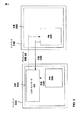
図3は、本開示の技法と合致し複数のディスプレイに分かれて画像を表示するように構成される複数のディスプレイ310A、310Bの1つの非限定的な例を示す。該当する構成が、ディスプレイ310A、310Bおよびグラフィクス処理エンジン314A、314Bのような該当するAおよびBの識別子と共に図3に示される。本明細書では、図3のこれら該当する構成が、該当する「A」および「B」で指定された構成間で共有される態様を説明する際に、図3に示された該当するAおよびBの識別子を伴わずに集合的に参照される。例えば、ディスプレイ310A、310Bは、「ディスプレイ310」として集合的に参照される。別の例として、グラフィクス処理エンジン314A、314Bは、「グラフィクス処理エンジン314」として集合的に参照される。別の例として、画像データ340A、340Bは、「画像データ340」として集合的に参照される。
FIG. 3 illustrates one non-limiting example of
一般的に言うと、グラフィクス処理エンジンは、ディスプレイ310によって(例えば、図1に示されるホストコントローラ115から)受け取られた画像データおよび/または複数のグラフィクス命令を処理して、画像データ340を出力するように構成され得る。
Generally speaking, the graphics processing engine processes image data and / or multiple graphics instructions received by the display 310 (eg, from the host controller 115 shown in FIG. 1) and
図3に示されるように、グラフィクス処理エンジン314はフレームバッファ338も含む。フレームバッファ338は表示のために画像データ340(例えば画素情報)を一時的または恒久的に記憶するように構成される任意のコンピュータ可読記憶媒体を備え得る。例えば、フレームバッファ338はランダムアクセスメモリ(RAM)、フラッシュメモリ、磁気ハードディスクメモリ、または、画像データ340のようなデータを記憶するように構成された任意の他の種類のコンポーネントなどの任意タイプの記憶コンポーネントを備え得る。いくつかの例では、グラフィクス処理エンジン314が、複数のグラフィクス命令を処理して、処理された画像データ340をフレームバッファ338に出力できる。
As shown in FIG. 3, the graphics processing engine 314 also includes a frame buffer 338. Frame buffer 338 may comprise any computer readable storage medium configured to temporarily or permanently store image data 340 (eg, pixel information) for display. For example, the frame buffer 338 may be any type of storage, such as random access memory (RAM), flash memory, magnetic hard disk memory, or any other type of component configured to store data such as
ディスプレイ制御モジュール339はフレームバッファ338に記憶された画像データ340をアクセスし、この画像データ340に基づいて画像を表示するためにディスプレイ310を制御するように構成され得る。いくつかの実装形態では、ディスプレイ制御モジュールが、グラフィクス処理エンジン314の一部であってよい。いくつかの例では、グラフィクス処理エンジンがまた、グラフィクス処理ユニット(GPU)を含み得る。
Display control module 339 may be configured to access
ディスプレイ310は、液晶ディスプレイ(LCD)、プラズマディスプレイ、リアプロジェクションディスプレイ、プロジェクタディスプレイ、陰極線管ディスプレイ、または任意の他の種類のディスプレイを備え得る。例えば、液晶ディスプレイまたはプラズマディスプレイは、ディスプレイの画面上にある(図3には示されない)複数のディスプレイ素子を含み得る。各ディスプレイ素子は、光を発し(または発しない)ように、かつ/または異なる色もしくは他の特性の光を発するように構成され得る。ディスプレイ制御モジュール339は、画像データ340に基づいてこのようなディスプレイ素子を制御できる。例えば、ディスプレイ制御モジュール339は、画像のある特定の画素が赤色であることを示す画素データ340に基づいて、このような画素を表す1つまたは複数のディスプレイ素子に、赤色の光を放出させることができる。
Display 310 may comprise a liquid crystal display (LCD), a plasma display, a rear projection display, a projector display, a cathode ray tube display, or any other type of display. For example, a liquid crystal display or plasma display may include a plurality of display elements (not shown in FIG. 3) that are on the screen of the display. Each display element may be configured to emit (or not emit) light and / or emit light of a different color or other characteristic. The display control module 339 can control such display elements based on the
図3にも示されるように、ディスプレイ310はクロック源332を含む。クロック源332は、基準クロック335を生成するように構成される水晶発振器または他のハードウェアおよび/もしくはソフトウェアコンポーネントのようなものであって、基準クロック335を生成するように構成される1つまたは複数のコンポーネントを含み得る。ディスプレイ310の1つまたは複数の他のコンポーネント、すなわちグラフィクス処理エンジン314、フレームバッファ338、およびまたはディスプレイ制御モジュール339などは生成された基準クロック335に基づいて動作できる。例えば、ディスプレイ制御モジュール339はクロック源332によって生成された基準クロックに基づいて画像の該当副部分(例えば線)を表示するようにディスプレイ310を制御できる。 As also shown in FIG. 3, the display 310 includes a clock source 332. The clock source 332 is one such as a crystal oscillator or other hardware and / or software component configured to generate the reference clock 335 and is configured to generate the reference clock 335 or It can include multiple components. One or more other components of display 310, such as graphics processing engine 314, frame buffer 338, and / or display control module 339, can operate based on the generated reference clock 335. For example, the display control module 339 can control the display 310 to display the corresponding sub-portion (eg, line) of the image based on the reference clock generated by the clock source 332.
いくつかの例によれば、ディスプレイ制御モジュール339は、ディスプレイ画面312を介する表示のために、基準クロック335に基づいてフレームバッファ338に記憶された画像データ340を読み取ることができる。例えば、ディスプレイ制御モジュール339は、基準クロック335に基づいて定義される間隔でフレームバッファ338に記憶された画像データ340の副部分(例えば線)を読み取ることができる。画像データ340のこのような副部分は、画像の表示部分の1つまたは複数の副部分(例えば、画像の第1または第2の部分の線)に対応し得る。
According to some examples, the display control module 339 can read the
図3のディスプレイ310Aに関して示されるように、フレームバッファ338Aは、画面312Aを介して表示される画像の第1の部分の線(図1に示されるような第1の画像部分116Aに対応する)に対応する副部分341〜346を含む画像データ340Aを有する。副部分341〜346は、1フレームの画像(例えば、ビデオシーケンスのような複数のフレームのシーケンスのうちのあるフレーム)に対応し得る。図3に示されるように、第1の部分の副部分345および346は、フレームバッファ338Aから読み取られており、画面312Aを介して表示されている。図3にも示されるように、第1の部分の副部分341〜344は、フレームバッファ339Aからまだ読み取られておらず、画面312Aを介して表示されていない。図3はまた、副部分345および346よりも前に画面312Aを介して表示されているいくつかの副部分(図3ではラベル付けされていない)も示す。このような副部分は、例えば、画像部分の同じフレームまたは別のフレーム(例えば、ディスプレイ制御モジュール339Aによってフレームバッファから以前に読み取られたフレーム)の副部分を備え得る。
As shown with respect to display 310A in FIG. 3, frame buffer 338A is a first portion line of an image displayed via
図3のディスプレイ310Bに関して示されるように、フレームバッファ338Bは、画面312Bを介して表示される画像の第2の部分(図1に示されるような第2の部分116B)の線に対応する副部分361〜366を含む画像データ340Bを有する。副部分361〜366は、1フレームの画像部分(例えば、ビデオシーケンスのような複数のフレームのシーケンスのうちのあるフレーム)に対応し得る。図3に示されるように、第2の部分の副部分363〜366は、フレームバッファ338Bから読み取られており、画面312Bを介して表示されている。図3にも示されるように、第2の部分の副部分361〜362は、フレームバッファ339Bからまだ読み取られておらず、画面312Bを介して表示されていない。図3はまた、副部分363〜366よりも前に画面312Bを介して表示されている、(図3では標識されない)いくつかの副部分も示す。このような副部分は、例えば、画像部分の同じフレームまたは別のフレーム(例えば、ディスプレイ制御モジュール339Bによってフレームバッファから以前に読み取られたフレーム)の副部分を備え得る。
As shown with respect to display 310B of FIG. 3, frame buffer 338B is a sub-corresponding to the line of the second portion of image (second portion 116B as shown in FIG. 1) displayed via
図3に示されるディスプレイ310A、310Bの各フレームバッファ339A、339Bは、全部で6本の線(例えば、線341〜346、線361〜366をそれぞれ含む)を各々含む該当画像部分を有する。図3の例は、本開示の技法を説明する目的で与えられる。いくつかの例では、本明細書で説明されるように表示されることになる画像または画像部分が、図3に示されたものよりも、画像データ340および対応する画面出力の線を多く含み得る。例えば、高解像度のディスプレイによって表示されるように構成される画像は、画像データ340の、720本または1080本の線、または任意の他の数の線を含み得る。
Each of the frame buffers 339A and 339B of the
図3の例によれば、ディスプレイ310Aは、画像の第1の部分(例えば図1に示される第1の部分116A)の2本の線345〜346を表示しているが、ディスプレイ310Bは、第2の部分316B(例えば図1に示される第2の部分116B)の4本の線363〜366を表示している。従って、第1の部分316Aおよび第2の部分316Bそれぞれを出力するディスプレイ310Aおよび310Bの動作は同期していない。いくつかの例では、図2に示されるような、ディスプレイ310Aおよび310Bの動作間における同期の欠如が、ディスプレイ310Aおよび310Bの該当クロック源332A、332Bからのクロック信号335A、335Bの差によって引き起こされ得る。
According to the example of FIG. 3, the
図3に示されるように、本開示の技法によれば、ディスプレイ310A、310Bの各々は、進行状況特定モジュールPIM 350A、350B(まとめてPIM 350)を含む。PIM 350は、ディスプレイ310の状態を判定して画像の部分を出力できる。例えば、PIM 350は、ディスプレイ制御モジュール339および/またはフレームバッファ338の動作を監視し、画像の部分を出力するためにディスプレイ310の状態を判定できる。
As shown in FIG. 3, according to the techniques of this disclosure, each of the
PIM 350は、画像部分の1つまたは複数の副部分(例えば線または画素)を表示するためにディスプレイ310の進行状況を判定できる。例えば、PIM 350は、ディスプレイ制御モジュール339の動作を監視し、ディスプレイ制御モジュール339によってフレームバッファから読み取られ表示されている画像の部分のある数の線または画素のような画像部分の副部分を表示できる。例えば、ディスプレイ310AのPIM 350Aは、ディスプレイ制御モジュール339Aを監視し、2本の線345〜346がフレームバッファ338によって読み取られ画面312Aを介して表示されているかどうかを判定できる。ディスプレイ310BのPIM 350Bは、ディスプレイ制御モジュール339Bを監視し、4本の線363〜366がフレームバッファ339によって読み取られ画面312Bを介して表示されているかどうかを判定できる。
PIM 350 can determine the progress of display 310 to display one or more sub-portions (eg, lines or pixels) of the image portion. For example, the PIM 350 monitors the operation of the display control module 339 and displays a sub-portion of the image portion, such as a number of lines or pixels of the portion of the image that is read from the frame buffer and displayed by the display control module 339. it can. For example, the
他の例によれば、PIM 350は、ディスプレイ制御モジュール339の動作を直接監視しなくてもよい。これらの例によれば、PIM 350は、ディスプレイ310の状態を判定して、フレームバッファ338の利用可能な空間および/または使われている空間の量を求めたことに基づいて画像の1つまたは複数の副部分を出力できる。例えば、PIM 350は、フレームバッファ338から読み取られ画面312を介して表示されるべき現在フレームの位置を示すポインタまたは他の参照マーカーの場所を求めることができる。 According to another example, PIM 350 may not directly monitor the operation of display control module 339. According to these examples, the PIM 350 determines the state of the display 310 and determines one or more of the images based on determining the amount of space available and / or used space in the frame buffer 338. Multiple subparts can be output. For example, PIM 350 may determine the location of a pointer or other reference marker that indicates the position of the current frame to be read from frame buffer 338 and displayed via screen 312.
別の例として、フレームバッファ338の利用可能な記憶サイズが、表示されるべき画像の線または画素の具体的な数(例えば1080本の線)を表し得る。この例によれば、PIM 350は、フレームバッファ338に記憶された画像データ340によって使われる利用可能な記憶空間の量を求め、それによって、画像の副部分(例えばある数の線または画素)の表示に関するディスプレイ310の進行状況を求めることができる。例えば、図3に示されるように、ディスプレイ310AのPIM 350Aは、フレームバッファ338Aを監視し、画像の第1の部分の2本の線345〜346がフレームバッファ338Aから読み取られ画面312Aを介して表示されていると判定できる。ディスプレイ310BのPIM 350Bは、フレームバッファ338Bを監視し、画像の第2の部分の4本の線363〜366がフレームバッファ339から読み取られ画面312Bを介して表示されていると判定できる。
As another example, the available storage size of the frame buffer 338 may represent a specific number of lines or pixels of an image to be displayed (eg, 1080 lines). According to this example, the PIM 350 determines the amount of available storage space used by the
いくつかの例では、ディスプレイ310を監視することに基づいて、画像部分の副部分(例えば線)の表示に関するディスプレイ310の進行状況を求めて、PIM 350が画像部分の1つまたは複数の副部分の表示に関するディスプレイ310の進行状況をホストコントローラ(例えば、図2に示されるホストコントローラ215)へ示すディスプレイ状態(例えば、図2に示されるようなディスプレイ状態218A、218B)を生成できる。例えば、PIM 350は、画像部分のフレームの出力に関するディスプレイ310の進行状況(例えば、ディスプレイ画面312を介して表示されている画像部分の線および/または画素の数)を示すディスプレイ状態(図3には示されない)を生成できる。PIM 350は、ディスプレイ状態を継続的に(例えば、フレームバッファ339に記憶される新規フレームの画像部分である画像データの副部分をフレームバッファ339へ記憶する/フレームバッファ339から読み取ることに関する基準クロック335の各々のクロック周期で)かつ/または1つまたは複数の所定の間隔に基づいて生成および/または通信できる。
In some examples, based on the monitoring the de Isupurei 310, seeking progress display 310 for presentation of the sub-portions of the image portion (e.g. linear), PIM 350 has one image portion or A display state (eg, display states 218A, 218B as shown in FIG. 2) can be generated that indicates to the host controller (eg,
いくつかの例では、PIM 350が、上で説明されたようなvsynch信号および/またはhsynch信号を備えるディスプレイ状態を生成できる。例えば、本明細書で説明されたようなディスプレイ310は、フレームバッファ338に記憶される画像のアクティブな副部分の表示を、画像の前のフレームの表示の後にある期間、遅らせるように構成され得る。このような期間は、垂直方向のブランキング線および/または水平方向のブランキング画素の数を含む、フレームの1つまたは複数のブランキング領域に基づき得る。いくつかの例では、水平方向のブランキング領域がhsynch領域(すなわちhsynch信号)を含んでよく、hsynch領域が画像部分のその前に表示されるフレームに対してディスプレイがフレームの画素の表示を遅らせる期間の少なくとも一部を示し得る。垂直方向のブランキング領域はvsynch領域(すなわちvsynch信号)を含んでよく、vsynch領域は画像部分のその前に表示されるフレームに対してディスプレイがフレームの線の表示を遅らせる期間の少なくとも一部を示し得る。これらの例によれば、PIM 350は、上で説明されたようなvsynch信号、hsynch信号、またはvsync信号とhsynch信号の両方を備えるディスプレイ状態218A、218Bを生成できる。 In some examples, the PIM 350 can generate a display state comprising a vsync signal and / or an hsync signal as described above. For example, display 310 as described herein may be configured to delay the display of the active sub-portion of the image stored in frame buffer 338 for a period of time after the display of the previous frame of the image. . Such a period may be based on one or more blanking regions of the frame, including the number of vertical blanking lines and / or horizontal blanking pixels. In some examples, the horizontal blanking region may include an hsync region (ie, an hsync signal), and the display delays the display of the pixels of the frame relative to the frame in which the hsync region is displayed prior to the image portion. It may indicate at least part of the period. The vertical blanking region may include a vsync region (ie, a vsync signal), where the vsync region is at least part of a time period during which the display delays the display of the frame lines relative to the frame displayed before it in the image portion. Can show. According to these examples, PIM 350 can generate display states 218A, 218B that comprise a vsync signal, an hsync signal, or both a vsync and hsync signal as described above.
いくつかの例では、PIM 350が、例えば、基準クロック335Aの各クロック周期ごとに、または、フレームバッファ338に記憶されもしくはフレームバッファ338から読み取られる画像データ340の各副部分ごとに、画像部分の副部分(例えば線および/または画素)の出力に関するディスプレイ310の進行状況のインジケーションを継続的に出力できる。他の例では、新規の画像部分(例えばビデオシーケンスの新たなフレーム)がフレームバッファ338に記憶される(またはフレームバッファ338から読み取られる)度に、PIM 350は副部分の出力に関するディスプレイ310の進行状況のインジケーションを出力するように動作できる。さらに他の例では、PIM 350が所定の間隔に従ってディスプレイ310の進行状況のインジケーションを出力できる。例えば、PIM 350は、フレームバッファ338に記憶されまたはフレームバッファ338から読み取られる画像データ340の5個の副部分ごとに、または、基準クロック335Aの20回のクロック周期ごとに、ディスプレイ310の進行状況を求めるように動作できる。いくつかの例では、PIM 350がディスプレイ310の状態を計数して画像データを表示するように構成されるカウンタ(図3には示されない)を含み得る。例えば、このようなカウンタは、画像データ340の副部分がフレームバッファ338に記憶される(またはフレームバッファ338から読み取られる)度に更新され得る。
In some examples, the PIM 350 may, for example, for each clock period of the
図2に戻ると、ホストコントローラ215は、複数のディスプレイ210A、210Bに分かれた画像を表示するために複数のディスプレイ210A、210Bを制御できる。本開示の技法によれば、ディスプレイ210A、210Bの各々は、図3に示されるPIM 350A、350Bに関して上で説明されたような進行状況特定モジュール(PIM)250A、250Bを含む。PIM 250A、250Bは各々該当するディスプレイ210A、210Bについて、該当する第1の画像部分216A、第2の画像部分216Bの1つまたは複数の副部分の出力に関する該当ディスプレイの進行状況を求め、第1の画像部分216A、第2の画像部分216Bの該当する副部分の表示に関する該当ディスプレイの進行状況を示すディスプレイ状態信号218A、218B(例えば、vsynchおよび/またはhsynch信号)を伝えることができる。本開示の技法によれば、ホストコントローラ215は、ディスプレイ状態信号218A、218Bを受け取り、それに応答して、少なくとも1つのディスプレイ状態信号219を生成することができ、ディスプレイ状態信号219は該当するディスプレイ210A、210Bによって表示されるべき第1の画像部分および/または第2の画像部分(例えば、図1に示されるような第1の画像部分116A、第2の画像部分116B)の少なくとも1つの副部分(例えば、少なくとも1つの線および/または画素)の表示を調整することを第1および第2のディスプレイ210A、210Bのうちの1つまたは複数に行わせるように構成される。
Returning to FIG. 2, the
図4は、ホストコントローラ415の一例を示すブロック図である。ホストコントローラ415は、複数のディスプレイ(例えば、図2に示されるディスプレイ210A、210B)を同時に制御するように構成される任意のデバイスを備え得る。例えば、ホストコントローラ415は、少なくとも2つのディスプレイへ通信可能に結合されて、かつ複数のディスプレイに分かれた少なくとも1つの画像を表示するために複数のディスプレイを制御するように構成される任意のデバイスを備え得る。いくつかの例では、ホストコントローラ415が、デスクトップコンピュータ、ゲームコンソール、ラップトップコンピュータ、スマートフォン、フィーチャーフォン、またはタブレットコンピュータ、デジタルメディアプレーヤ、または、複数のディスプレイを制御してこれらディスプレイに分かれた画像を表示させるように構成される任意の他のデバイスなどのコンピューティングデバイスを備え得る。 FIG. 4 is a block diagram illustrating an example of the host controller 415. The host controller 415 may comprise any device configured to control multiple displays (eg, displays 210A, 210B shown in FIG. 2) simultaneously. For example, the host controller 415 can be any device that is communicatively coupled to at least two displays and configured to control the plurality of displays to display at least one image that is divided into the plurality of displays. Can be prepared. In some examples, the host controller 415 controls a desktop computer, a game console, a laptop computer, a smartphone, a feature phone, or a tablet computer, a digital media player, or multiple displays to display an image that is divided into these displays. A computing device such as any other device configured to be displayed may be provided.
図4に示されるように、ホストコントローラ415は、少なくとも1つのプロセッサ475を含み得る。プロセッサ475は、複数のプログラム命令を処理するように構成される任意のコンポーネントを含み得る。例えば、プロセッサ475は1つまたは複数の中央演算処理装置(CPU)、グラフィクス処理ユニット(GPU)、特定用途向け集積回路(ASIC)、フィールドプログラマブルゲートアレイ(FPGA)、または命令を処理するように構成される任意の他のコンポーネントを含み得る。プロセッサ475は、複数のプログラム命令を実行して、本明細書で説明された技法に合致して動作することをホストコントローラ415に行わせることができる。
As shown in FIG. 4, the host controller 415 may include at least one
図4にも示されるように、ホストコントローラ415は通信モジュール476を含む。通信モジュール476は、ホストコントローラ475が複数のディスプレイ(例えば、図2に示されるディスプレイ210A、210B)および/または他のコンピューティングデバイスと通信することを可能にできる。例えば、通信モジュール476は、ホストコントローラ575と複数のディスプレイおよび/または他のコンピューティングデバイスとの間において有線通信(例えば、イーサネット(登録商標)、digital video input(DVI(登録商標))、high−definition multimedia interface HDMI(登録商標))、またはワイヤレス通信(Wi−Fi(登録商標)、セルラーネットワーク、Bluetooth(登録商標))を可能にするように構成され得る。
As also shown in FIG. 4, the host controller 415 includes a
図4にも示されるように、ホストコントローラ415は、少なくとも1つの記憶コンポーネント478をさらに含む。記憶コンポーネント478は、データおよび/または複数の実行可能命令、例えば、本開示の技法に合致して動作することをホストコントローラに行わせるためのもので、プロセッサ475によって実行可能な複数の命令を記憶するように構成される任意のコンポーネントを備え得る。例えば、記憶コンポーネント478は、ランダムアクセスメモリ(RAM)、フラッシュメモリ、磁気ハードディスクメモリ、光学メモリ、または、データもしくは複数の命令を一時的にもしくは長期的に記憶するように構成される任意の他の種類のコンポーネントを含む、任意の種類の記憶コンポーネントを備え得る。
As also shown in FIG. 4, the host controller 415 further includes at least one storage component 478. Storage component 478 stores data and / or a plurality of executable instructions, eg, a plurality of instructions executable by
図4に示されるように、ホストコントローラ415はグラフィクス制御モジュール477も含む。いくつかの例では、グラフィクス制御モジュール477が表示される画像に関連する複数の命令および/またはデータ、例えば、複数のディスプレイ(例えば、図3に示されるディスプレイ310A、310B)の該当するグラフィクス処理モジュール(例えば、図3に示されるグラフィクス処理エンジン314A、314B)が解釈可能な画像データおよび/または複数のグラフィクス命令を伝えることができる。本明細書で説明されるように、いくつかの例では、第1のディスプレイに伝えられる画像データおよび/または複数のグラフィクス命令417Aが、第2のディスプレイに伝えられる画像データおよび/または複数のグラフィクス命令417Bとは異なり得る。しかし、他の例では、画像データおよび/または複数のグラフィクス命令の少なくとも一部が画像データおよび/または複数のグラフィクス命令の少なくとも一部と同じであってよい。
As shown in FIG. 4, the host controller 415 also includes a graphics control module 477. In some examples, the graphics control module 477 is associated with a plurality of instructions and / or data related to the displayed image, eg, a corresponding graphics processing module of a plurality of displays (eg, displays 310A, 310B shown in FIG. 3). Image data and / or a plurality of graphics instructions that can be interpreted (eg, the
いくつかの例では、グラフィクス制御モジュール477が、プロセッサ475によって実行可能な複数の命令、例えば、複数の命令および/またはデータを生成して複数のディスプレイへ伝えるもので、かつプロセッサ475上で実行されるアプリケーションを備え得る。例えば、このようなアプリケーションは、ユーザの入力、または、別のコンピューティングデバイス(図4には示されない)から受け取られた入力に応答して、画像データおよび/または複数のグラフィクス命令を生成し伝えることができる。別の例によれば、グラフィクス制御モジュール477は、ホストコントローラ415のメモリコンポーネントに記憶された、または、ホストコントローラ415に通信可能に結合される別のコンピューティングデバイスから受け取られた画像データおよび/または複数のグラフィクス命令(例えば、流された画像データ)を伝えるように構成されるホストコントローラ415のソフトウェアおよび/またはハードウェアを備え得る。
In some examples, the graphics control module 477 generates instructions that can be executed by the
図4に示されるように、ホストコントローラ415はオフセット測定モジュール(ODM)480を含む。図4に示されるように、ODM 480は複数のディスプレイの各々のディスプレイ状態418A、418Bを、ホストコントローラ475に通信可能に結合された第1のディスプレイおよび第2のディスプレイ(例えば、図2に示されるディスプレイ210A、210B)から受け取る(例えば、図4に示される通信モジュール476を介して)ことができる。受け取られたディスプレイ状態418A、418Bは各々、上で説明されたように、画像の該当部分の表示に関し該当する第1のディスプレイおよび第2のディスプレイの進行状況を示すことができる。例えば、ディスプレイ状態418A、418Bは、画像の該当部分の出力のタイミングを示すことができる。別の例によれば、ディスプレイ状態は、複数のディスプレイに分かれ該当ディスプレイによって出力されている画像の該当する第1の部分および第2の部分(例えば、図1に示されるような、画像116の第1の部分116A、第2の部分116B)の副部分の数(例えば、線および/または画素の数)を示すことができる。いくつかの例では、図3を参照して上で説明されたように、ディスプレイ状態418A、418Bが画像116の第1の部分116Aまたは第2の部分116Bの少なくとも1つのフレームと関連付けられるvsynch信号および/またはhsynch信号を含み得る。
As shown in FIG. 4, the host controller 415 includes an offset measurement module (ODM) 480. As shown in FIG. 4, ODM 480 displays the display state 418A, 418B of each of the plurality of displays in a first display and a second display (eg, as shown in FIG. 2) that are communicatively coupled to
いくつかの例では、ODM 480が、受け取られた第1のディスプレイ状態418Aおよび第2のディスプレイ状態418Bを互いに比較して、第1のディスプレイおよび第2のディスプレイ間のオフセット455を求めることができる。例えば、第1のディスプレイ状態418A、第2のディスプレイ状態418Bに基づき、ODM 480は、第1のディスプレイによって表示される線の数と、第2のディスプレイによって表示される線の数とを比較でき、これにより例えば第1のディスプレイおよび第2のディスプレイが互いにどの程度同期から外れているかの測定値となる差を求めることができる。例えば、ODM 480は、本明細書で説明されたようなhsynch信号および/またはvsynch信号のうちの1つまたは複数を備えるディスプレイ状態418A、418Bに基づき、該当する第1の画像部分および第2の画像部分を表示する際の、該当する第1のディスプレイおよび第2のディスプレイの表示と関連付けられる遅延を求めることができ、これによりディスプレイ状態418A、418Bに基づいて画像の第1の部分および第2の部分を表示するための該当ディスプレイの動作の差を求めることができる。ディスプレイ状態418A、418Bに基づき、ODM 480はこうして求められた差を示すオフセット455を生成し得る。 In some examples, ODM 480 may compare received first display state 418A and second display state 418B to each other to determine an offset 455 between the first display and the second display. . For example, based on the first display state 418A and the second display state 418B, the ODM 480 can compare the number of lines displayed by the first display with the number of lines displayed by the second display. Thus, for example, it is possible to determine a difference that is a measurement value of how far the first display and the second display are out of synchronization with each other. For example, the ODM 480 may be configured based on display states 418A, 418B comprising one or more of hsync and / or vsync signals as described herein, and the corresponding first image portion and second A delay associated with displaying the corresponding first and second displays in displaying the image portion can be determined, thereby determining the first and second portions of the image based on display states 418A, 418B. The difference in the operation of the corresponding display for displaying the part can be obtained. Based on display states 418A, 418B, ODM 480 may generate an offset 455 that indicates the difference thus determined.
図4にも示されるように、ホストコントローラ415は調整制御モジュール482をさらに含む。調整制御モジュール482は求められたオフセット455をODM 480から受け取ることができる。求められたオフセット455に基づき、調整制御モジュール482は複数のディスプレイの少なくとも1つにディスプレイ調整419を伝えても伝えなくてもよい。 As also shown in FIG. 4, the host controller 415 further includes an adjustment control module 482. The adjustment control module 482 can receive the determined offset 455 from the ODM 480. Based on the determined offset 455, adjustment control module 482 may or may not communicate display adjustment 419 to at least one of the plurality of displays.
一例によれば、調整制御モジュール482は、オフセット455が複数のディスプレイの間で求められたかどうかに基づいて複数のディスプレイの少なくとも1つへディスプレイ調整419を伝えることができる。他の例では、調整制御モジュール482が、求められたオフセット455と所定の閾値との比較に基づいてディスプレイ調整419を伝えるように構成され得る。このような所定の閾値は、例えば、画像の該当する部分を表示するための複数のディスプレイの動作の時間差、または、複数のディスプレイによって表示される画像の該当する部分の1つまたは複数の副部分を表示するための複数のディスプレイの動作における線の数の差を示すことができる。このような所定の閾値は、いくつかの例では、複数のディスプレイ間での同期の欠如が、画像の第1の部分および第2の部分の表示において望ましくない影響を引き起こし得る期間および/または副部分の数に基づき得る。1つのそうした例として、このような所定の閾値は、5本の線という差を示し得る。この例によれば、調整制御モジュール482は、求められたオフセット455が5本の線以上である場合に複数のディスプレイの少なくとも1つへディスプレイ調整419を伝えることができる。 According to an example, the adjustment control module 482 can communicate the display adjustment 419 to at least one of the plurality of displays based on whether the offset 455 is determined between the plurality of displays. In other examples, the adjustment control module 482 may be configured to communicate the display adjustment 419 based on a comparison of the determined offset 455 and a predetermined threshold. Such a predetermined threshold is, for example, a time difference between operations of a plurality of displays for displaying a corresponding part of an image, or one or a plurality of sub-parts of a corresponding part of an image displayed by a plurality of displays. The difference in the number of lines in the operation of the multiple displays for displaying can be shown. Such a predetermined threshold is, in some examples, a period and / or sub-level where lack of synchronization between multiple displays can cause undesirable effects in the display of the first and second portions of the image. Based on the number of parts. As one such example, such a predetermined threshold may indicate a difference of 5 lines. According to this example, adjustment control module 482 can communicate display adjustment 419 to at least one of the plurality of displays when the determined offset 455 is greater than or equal to five lines.
他の例では、調整制御モジュール482が、求められたオフセット455に基づいてリセットを伝えるようにさらに構成され得る。例えば、調整制御モジュール482は、受け取られたオフセット455をリセット閾値と比較することができ、リセット閾値は、画像部分の1つまたは複数の副部分の表示の調整が複数のディスプレイに分けて画像を表示する複数のディスプレイを同期させるうえで不十分であり得る副部分(例えば線)の数のオフセットを示す。例えば、調整制御モジュール482は、該当ディスプレイの1つまたは複数のクロック生成コンポーネントを初期状態にリセットすることを複数のディスプレイに行わせるように構成されるリセットを伝えることができる。他の例によれば、リセットモジュールは、共通の時間においてフレームバッファをクリアし、該当する画像部分の表示を開始することを複数のディスプレイの1つまたは複数に行わせることができる。具体的には、2つのディスプレイがある場合、調整制御モジュール482は、両方のディスプレイが同時に表示を再び開始するように、各ディスプレイに自身のフレームバッファのリセットとクリアとを行わせることができる。例えば、ディスプレイ調整モジュール482は、現在フレームをディスプレイの該当するフレームバッファへリロードすることを該当ディスプレイに行わせたり、現在フレームをクリアし、ビデオシーケンスの次フレームに対応する画像データをロードすることを該当ディスプレイに行わせたりするように構成されるリセットを伝えることができる。

上の表1は、求められたオフセット455に応じ、調整制御モジュール482によって伝えられ得るディスプレイ調整419の1つの非限定的な例を示す。表1の例によれば、ディスプレイ調整419の命令は、8ビットのデータを含む。第1のビットD0は、複数のフレーム(ビデオシーケンスを備える画像116の第1の部分116Aの)のうちのどのフレームにシフトを適用すべきか(例えば、ブランキング線の数を調整すべきか)を示す。この例によれば、0という値は、ディスプレイがディスプレイ調整419を次フレームの画像の部分に適用すべきであることを示し得る。また、この例によれば、1という値は、ディスプレイがディスプレイ調整419を次フレームの画像の部分の後のフレームに適用すべきであることを示し得る。これらの例によれば、ホストコントローラ415の調整制御モジュール482は、次フレームの画像の部分またはさらにこの後のフレームに対してディスプレイ調整を適用すべきかどうかを現在フレームの出力に関するディスプレイの状態に基づいて判定できる。例えば、ディスプレイがディスプレイ調整を処理し、次フレームに対してディスプレイ調整を適用するのに十分な時間がある場合には、調整制御モジュール482がディスプレイ調整を次フレームに適用すべきかどうかを判定できる。しかし、次フレームにディスプレイ調整を適用するのに十分な時間がない場合には、調整制御モジュール482が次フレームの後のさらなるフレームにディスプレイ調整を適用できる。
Table 1 above shows one non-limiting example of a display adjustment 419 that can be conveyed by the adjustment control module 482 depending on the determined offset 455. According to the example of Table 1, the display adjustment 419 instruction includes 8-bit data. The first bit D0 indicates to which frame of the plurality of frames (in the
表1の例によれば、ディスプレイ調整419の第2のビットD1から第6のビットD5は、追加または削除すべき画像データのフレームと関連付けられるブランキング線および/またはブランキング画素の数を示す。この例によれば、ディスプレイ調整419は、追加または削除すべき1〜32本のブランキング線を示し得る。また、表1の例によれば、ディスプレイ調整419の第7のビットD6は指示を備える。この指示は、ビットD1〜D5によって示された数のブランキング線および/またはブランキング画素を、追加する(フレームのアクティブな線を表示する際の遅延を大きくする)か、または削除する(フレーム線のアクティブな線を表示する際の遅延を小さくする)かどうかを示すことができる。表1の例によれば、ビットD6が値1を割り当てられる場合、ディスプレイはビットD1〜D5によって示される数のブランキング線を追加できる。ビットD6が値0を割り当てられる場合、ディスプレイがビットD1〜D5によって示される数のブランキング線を削除できる。 According to the example in Table 1, the second bit D1 to the sixth bit D5 of the display adjustment 419 indicate the number of blanking lines and / or blanking pixels associated with the frame of image data to be added or deleted. . According to this example, display adjustment 419 may show 1 to 32 blanking lines to be added or deleted. Also according to the example in Table 1, the seventh bit D6 of the display adjustment 419 comprises an indication. This indication either adds (increases the delay in displaying the active line of the frame) or deletes (frames) the number of blanking lines and / or blanking pixels indicated by bits D1-D5. Whether to reduce the delay in displaying the active line). According to the example in Table 1, if bit D6 is assigned the value 1, the display can add the number of blanking lines indicated by bits D1-D5. If bit D6 is assigned the value 0, the display can delete the number of blanking lines indicated by bits D1-D5.
いくつかの例において、ホストコントローラ315は、上の表1に示されるようなディスプレイ調整を伝え、画像データの複数の異なるフレームに対するアクティブな線および/または画素のデータの表示を調整するように構成され得る。例えば、ホストコントローラは、例えば32本の線またはそれよりも少ない所定の閾値未満のディスプレイ調整を伝えるように構成され得る。これらの例によれば、ホストコントローラ315が画像データの複数のフレームと関連付けられる複数のディスプレイ調整信号を伝え、本明細書で説明されるように複数のディスプレイを徐々に同期させることができる。 In some examples, the host controller 315 communicates display adjustments as shown in Table 1 above and is configured to adjust the display of active line and / or pixel data for multiple different frames of image data. Can be done. For example, the host controller may be configured to communicate display adjustments below a predetermined threshold, eg, 32 lines or less. According to these examples, the host controller 315 can convey a plurality of display adjustment signals associated with a plurality of frames of image data and gradually synchronize the plurality of displays as described herein.
また、表1の例によれば、ディスプレイ調整419の第8のビットD7がリセットを示す。リセットは、ディスプレイの1つまたは複数のクロック生成コンポーネントをリセットするようにディスプレイに指示できる。例えばビットD7が値1を有する場合には、ディスプレイが現在フレームまたは今後のフレームにおいて画像の表示をリセットできる。しかし、ビットD7が値0を有する場合には、ディスプレイがビットD0〜D6によって示される線の数、指示、および/またはフレームに従って画像の少なくとも1つのフレームと関連付けられる数のブランキング線および/またはブランキング画素を追加または削除するように動作できる。 Also, according to the example of Table 1, the eighth bit D7 of the display adjustment 419 indicates reset. The reset can instruct the display to reset one or more clock generation components of the display. For example, if bit D7 has the value 1, the display can reset the display of the image in the current frame or a future frame. However, if bit D7 has the value 0, the number of blanking lines and / or the display associated with at least one frame of the image according to the number, indication, and / or frame of lines indicated by bits D0-D6 Can operate to add or remove blanking pixels.
図3の例に戻ると、第1のディスプレイ310Aは画面310Aを介して線345〜346を表示するように動作しており、第2のディスプレイ310Bは画面312Bを介して線363〜366を表示するように動作している。この例によれば、ホストコントローラ415(例えばODM 480)は複数のディスプレイの各々から(例えば、図3に示されるディスプレイ310A、310BのPIM 350A、350Bから)ディスプレイ状態418A、418Bを受け取ることができる。ODM 482は、受け取られたディスプレイ状態418Aおよび418Bを互いに比較し、該当ディスプレイの動作間のオフセット455を求めることができる。図3の例によれば、ディスプレイ310Bは、ディスプレイ310Aが第1の画像について表示した線よりも2本多くの線を第2の画像について表示しているので、ODM 480は、ディスプレイ310Aおよび310Bの動作の間に2本の線のオフセットがあると判定できる。
Returning to the example of FIG. 3, the
ディスプレイ調整制御モジュール482は、ディスプレイ調整419を第2のディスプレイ310Bに伝えることができる。一例において、調整制御モジュール482は、求められたオフセット455が存在する(例えばオフセット455が0より大きい)かどうかに基づいてディスプレイ調整419を伝えることができる。他の例において、調整制御モジュール482は、求められたオフセット455を所定の閾値と比較して、ディスプレイ調整419を伝えるかどうかを判定できる。図3の例によれば、求められたオフセット455が2本の線である場合に、所定の閾値が1本の線であれば、調整制御モジュール482が2本の線という求められたオフセットに基づいてディスプレイ調整419を伝えることができる。しかし、所定の閾値が3本以上の線である場合において、調整制御モジュール482は2本の線という求められたオフセット455に基づいて遅延を伝えなくてよい。 Display adjustment control module 482 may communicate display adjustment 419 to second display 310B. In one example, the adjustment control module 482 can communicate the display adjustment 419 based on whether the determined offset 455 exists (eg, the offset 455 is greater than 0). In other examples, the adjustment control module 482 can compare the determined offset 455 with a predetermined threshold to determine whether to communicate the display adjustment 419. According to the example of FIG. 3, when the determined offset 455 is two lines and the predetermined threshold is one line, the adjustment control module 482 sets the calculated offset to two lines. Based on this, display adjustment 419 can be communicated. However, in the case where the predetermined threshold is three or more lines, the adjustment control module 482 does not have to convey the delay based on the determined offset 455 of two lines.
一例において、ディスプレイ調整419は、画像の第2の部分(例えば図1の第2の部分110B)のさらなる線の出力を遅延させることを第2のディスプレイ310Bに行わせることができる。例えば、図3の例によれば、ディスプレイ調整419によって、フレームバッファ339B(すなわち次フレームと関連付けられる)に記憶されるデータと関連付けられる1本または複数のブランキング線を追加できるので、例えば、フレームバッファ339Bに記憶される画像データの線および/または画素は、現在フレームおよび次フレームの表示の間でより長く遅延させられる。この例によれば、ディスプレイ調整によって、該当する画像部分の線および/または画素を実質的に同時に表示することができ、これによってディスプレイ110A、110Bに分かれた画像の該当部分の表示に関して、ディスプレイ110A、110Bの動作を同期させる。いくつかの例では、ディスプレイ調整(すなわち、追加の/削除されたブランキング線)が各ディスプレイ調整419を出した後、1回だけ実行する(すなわち、例えば1つの連続するフレームにのみ適用する)ことができ、この後、ディスプレイのタイミングは、標準の数のブランキング線および/またはブランキング画素を使って動作するように戻る。
In one example, display adjustment 419 may cause second display 310B to delay the output of additional lines of a second portion of the image (eg, second portion 110B of FIG. 1). For example, according to the example of FIG. 3, display adjustment 419 can add one or more blanking lines associated with data stored in frame buffer 339B (ie, associated with the next frame), so that, for example, frame The lines and / or pixels of image data stored in buffer 339B are delayed longer between the display of the current frame and the next frame. According to this example, the line adjustment and / or the pixels of the corresponding image portion can be displayed substantially simultaneously by the display adjustment, whereby the
別の例では、ディスプレイ調整419が、画像の第1の部分(例えば図1の第1の部分110A)の少なくとも1つの前のフレームに対する画像の第1の部分の線および/または画素の遅延を低減させることを第2のディスプレイ310Aに行わせることができる。例えば、図3の例でも、ディスプレイ調整419によって、フレームと関連付けられるブランキングデータの1つまたは複数の線および/または画素を削除できるので、例えば、画像の第2の部分の線の表示の遅延は少なくとも1つの前のフレームに対する遅延よりも短い。この例によれば、ディスプレイ調整419によって、少なくとも1つのこの後のフレームの線342および362を実質的に同時に表示することができ、これによって、ディスプレイ110A、110Bに分かれた画像の該当部分を表示するためにディスプレイ110A、110Bの動作を同期させる。
In another example, display adjustment 419 may reduce line and / or pixel delay of the first portion of the image relative to at least one previous frame of the first portion of the image (eg,
さらに別の例において、調整制御モジュール482は複数のディスプレイ調整を伝えるように構成され得る。例えば、図3の例によれば、調整制御モジュール418は、ディスプレイ110Aに1つのブランキング線および/またはブランキング画素を削除させる第1のディスプレイ調整と、ディスプレイ110Bに1つのブランキング線および/またはブランキング画素を追加させる第2のディスプレイ調整とを伝えることができる。この例によれば、少なくとも1つのこの後のフレームに対する線342の表示は時間的に先へと延ばされ、従って、遅れている線362と同期する。この例によれば、ディスプレイ調整419によって、線342と362とを実質的に同時に表示することができ、これによって、ディスプレイ110A、110Bに分かれた画像の該当部分を表示するためにディスプレイ110A、110Bの動作を同期させる。
In yet another example, adjustment control module 482 may be configured to communicate multiple display adjustments. For example, according to the example of FIG. 3, the adjustment control module 418 may perform a first display adjustment that causes the
複数のディスプレイに分かれた画像を表示するために本明細書で説明される技法は、いくつかの理由で有利であり得る。例えば、本開示の技法は、基準クロック335Aおよび335Bを互いに同期させることなく、ディスプレイ310A、310Bに分かれた第1の画像部分および第2の画像部分の同期を実現する。従って、これらの技法によれば、画像の該当する部分は実装が複雑で、高価で、かつ/または難しい、クロック同期コンポーネントまたは技法を使わずに、複数のディスプレイに分かれ得る。
The techniques described herein for displaying a split image on multiple displays may be advantageous for several reasons. For example, the techniques of this disclosure provide synchronization of the first image portion and the second image portion separated into
上で説明された図3の例は、画像(例えば画像116)の該当する部分(例えば、図1に示された第1の部分116A、第2の部分116B)を表示するように動作可能な2つのディスプレイ310A、310Bを含む。他の例では、ホストコントローラ415が、3つ以上のディスプレイに分かれた画像の表示を制御するように動作可能であってよい。ホストコントローラは、3つのディスプレイに分かれた画像の表示を制御するように動作可能である一例によれば、ODM 480が、図4に示されるように、2つのディスプレイ状態(418A、418B)の代わりに、3つのディスプレイ状態418を受け取ることができる。この例によれば、ODM 480は、受け取られたディスプレイ状態418の各々を互いに比較できる。ODM 480は、3つのディスプレイのうちの1つを、基準として指定できる。ODM 480は、基準のディスプレイに対する、各々の他のディスプレイのオフセット455を求めることができる。この例によれば、調整制御モジュール482は、2つ以上のディスプレイ調整419を伝えて、上で説明されたようにディスプレイの1つまたは複数の動作を調整できる。この例によれば、ホストコントローラ215は、3つ以上のディスプレイに分かれた画像を同期させて表示するように動作できる。
The example of FIG. 3 described above is operable to display corresponding portions (eg,
上で論じられ、図1、図2に示される例では、ホストコントローラ215、415が、ディスプレイ110A、110B、210A、210Bとは別個のデバイスとして示される。他の例では、ディスプレイの1つまたは複数自体が、上で説明されたようなホストコントローラとして動作するように構成され得る。
In the example discussed above and shown in FIGS. 1 and 2, the
図5は、本開示の技法に合致し複数のディスプレイ510A、510Bにわたってディスプレイの表示を制御するように動作可能なホストコントローラ515の一例を示すブロック図であり、複数のディスプレイの少なくとも1つはホストコントローラ515を含む。図5の例では、ディスプレイ510Aがホストコントローラ515を含む。図5に示されたホストコントローラ515は、ディスプレイ510Aおよび/または1つもしくは複数の他のハードウェアコンポーネントの1つまたは複数のプロセッサ(例えば、図5には示されないGPU、CPU)によって実行可能な複数のソフトウェア命令を備え得る。図2に示されるホストコントローラ215と同様に、第1のディスプレイ510Aのホストコントローラ515は上で説明されたような画像データおよび/または複数のグラフィクス命令を出力し、画面512A、512Bを介した、ディスプレイ510A、510Bに分かれた画像の表示を制御するように構成され得る。
FIG. 5 is a block diagram illustrating an example of a host controller 515 consistent with the techniques of this disclosure and operable to control the display of displays across
図5に示されるように、ホストコントローラ515は、ディスプレイ518A、518Bの該当するPIM 550A、550Bから、ディスプレイ状態550A、550Bを受け取るように構成される。ホストコントローラ515Aは、(例えば、図5には示されない、第1のディスプレイ510Aの通信モジュールを介して)第1のディスプレイ510の内部からディスプレイ状態518Aを受け取り、ディスプレイ510Bからディスプレイ状態518Bを受け取ることができる。
As shown in FIG. 5, the host controller 515 is configured to receive
受け取られたディスプレイ状態518A、518Bは各々該当ディスプレイ510A、510Bの状態を示し、ディスプレイ510A、510Bにわたって表示される画像の該当する第1の部分および第2の部分の1つまたは複数の副部分(例えば線)を出力できる。ホストコントローラ515は、受け取られた状態518A、518Bを互いにかつ/または上で説明されたような所定の閾値と比較できる。この比較に応じて、ホストコントローラ515は、少なくとも1つのディスプレイ調整519を第1のディスプレイ510Aと第2のディスプレイ510Bの1つまたは複数に対して伝えることができる。例えば、ディスプレイ510Aが第1の画像部分について表示している副部分が、ディスプレイ510Bが第2の画像部分について表示している副部分よりも少ないことを上記の比較が示す場合、ホストコントローラ515がディスプレイ調整をディスプレイ510Aの内部(例えば、ディスプレイ510Aの調整制御モジュール482)に伝えて、少なくとも1つのその前に表示されるフレームに対する、第1の画像部分のフレームの少なくとも1つの副部分の表示の遅延をディスプレイ510Aに低減させることができる。別の例によれば、ホストコントローラ515は、ディスプレイ調整をディスプレイ510B(例えば、ディスプレイ510Bの調整制御モジュール482)に伝えて、少なくとも1つのその前に表示されるフレームに対する、第2の画像部分のフレームの少なくとも1つの副部分の表示の遅延をディスプレイ510Bに拡大させることができる。このようにして、ディスプレイ510Aのホストコントローラ515は、第1のディスプレイ510A、第2のディスプレイ510Bの動作を同期させ、ディスプレイ510A、510Bに分かれた画像の該当する第1の部分および第2の部分を表示できる。
The received display states 518A, 518B indicate the state of the
いくつかの例では、複数のディスプレイの2つ以上が、複数のディスプレイに分かれた画像を制御するように構成されるホストコントローラ515として動作するように構成され得る。これらの例によれば、複数のディスプレイは、複数のディスプレイのうちのどのディスプレイがホストコントローラ515として動作するのに最も適しているかを判定するために互いに通信するように構成されてもよい。例えば、複数のディスプレイの1つまたは複数は、複数のディスプレイの各々が利用可能なコンピューティングリソース、メモリリソース、通信リソース、および/または電力リソースの量を求め、複数のディスプレイのうちの1つに大半の利用可能なリソースを割り当てて、本明細書で説明されたようなホストコントローラ515として動作させることができる。 In some examples, two or more of the plurality of displays may be configured to operate as a host controller 515 configured to control an image that is divided into the plurality of displays. According to these examples, the plurality of displays may be configured to communicate with each other to determine which of the plurality of displays is best suited to operate as the host controller 515. For example, one or more of the plurality of displays determines the amount of computing resources, memory resources, communication resources, and / or power resources that each of the plurality of displays can use, and becomes one of the plurality of displays. Most available resources can be allocated to operate as a host controller 515 as described herein.
図6は、本開示の技法に合致し少なくとも1つの画像の表示を複数のディスプレイに分けるように複数のディスプレイを制御する方法の一例を示す流れ図である。図1に示されるように、コンピューティングデバイスのホストコントローラ115、215、415、515は、第1のディスプレイ状態118A、218A、518Aを受け取ることができる(601)。第1のディスプレイ状態は、画像116の第1の部分116Aの少なくとも1つの副部分(例えば線341〜346の少なくとも1つ)の表示に関する第1のディスプレイ110A、210A、310A、510Aの進行状況を示すことができる。図1にも示されるように、ホストコントローラは、第2のディスプレイ状態118B、218B、518Bを受け取ることができる(602)。第2のディスプレイ状態は、画像116の第2の部分116Bの少なくとも1つの副部分(例えば少なくとも1つの線361〜366)の表示に関する第2のディスプレイ110B、210B、310B、510Bの進行状況を示すことができる。
FIG. 6 is a flow diagram illustrating an example of a method for controlling multiple displays to match the techniques of this disclosure and to divide the display of at least one image into multiple displays. As shown in FIG. 1, the
図6にも示されるように、ホストコントローラは、第1のディスプレイ状態および第2のディスプレイ状態(603)に基づいてオフセット455を求めることができる。オフセットは、画像の第1の部分を出力するための第1のディスプレイの状態と、画像の第2の部分を出力するための第2のディスプレイの状態との差を示す。ホストコントローラはさらに、求められたオフセットに基づいて、画像の第1の部分を表示するための第1のディスプレイと、画像の第2の部分を表示するための第2のディスプレイとの少なくとも1つを遅らせることができる(604)。例えば、ホストコントローラは、第1のディスプレイおよび第2のディスプレイの少なくとも1つに対して画像の第1の部分または第2の部分の少なくとも1つの副部分(例えば、線および/または画素)の表示時間を修正するように指示するディスプレイ調整を伝えることができる。いくつかの例では、ディスプレイ調整を用いてタイミング調整が実行された後、画像の該当する第1の部分および第2の部分を表示するための第1のディスプレイの動作および第2のディスプレイの動作の間で求められたオフセットが閾値よりも大きくなる次の時まで、ディスプレイが通常のブランキングパラメータ(例えば、標準の数のブランキング線および/またはブランキング画素)で動作できる。いくつかの例では、複数のディスプレイの動作を同期するために、単一のディスプレイ調整がホストコントローラによって使われ得る。他の例では、画像部分の2つ以上の表示されるフレームの進行を通じて、複数のディスプレイの動作を同期させるために、複数のディスプレイ調整信号がホストコントローラによって使われ得る。 As also shown in FIG. 6, the host controller can determine the offset 455 based on the first display state and the second display state (603). The offset indicates the difference between the state of the first display for outputting the first part of the image and the state of the second display for outputting the second part of the image. The host controller further includes at least one of a first display for displaying the first portion of the image and a second display for displaying the second portion of the image based on the determined offset. Can be delayed (604). For example, the host controller may display at least one sub-portion (eg, line and / or pixel) of the first portion or second portion of the image relative to at least one of the first display and the second display. A display adjustment can be communicated instructing the time to be corrected. In some examples, after the timing adjustment is performed using display adjustment, the operation of the first display and the operation of the second display to display the corresponding first and second portions of the image. The display can operate with normal blanking parameters (eg, a standard number of blanking lines and / or blanking pixels) until the next time the offset determined between is greater than the threshold. In some examples, a single display adjustment can be used by the host controller to synchronize the operation of multiple displays. In another example, multiple display adjustment signals may be used by the host controller to synchronize the operation of multiple displays through the progression of two or more displayed frames of the image portion.
本明細書で説明された技術は、ハードウェア、ソフトウェア、ファームウェア、またはそれらの任意の組合せで実装され得る。また、モジュールまたは構成要素として説明される特徴は、集積論理デバイスに一緒に、またはディスクリートであるが同時使用可能な論理デバイスとして別々に実装され得る。ソフトウェアで実装された場合、本技法は、実行されたときに、上記で説明された方法の1つまたは複数を実行する複数の命令を備える有形コンピュータ可読記憶媒体によって少なくとも部分的に実現され得る。有形コンピュータ可読データ記憶媒体は、パッケージング材料を含むことがあるコンピュータプログラム製品の一部を形成し得る。 The techniques described herein may be implemented in hardware, software, firmware, or any combination thereof. Also, features described as modules or components may be implemented together in an integrated logical device or separately as a discrete but simultaneously usable logical device. When implemented in software, the techniques may be implemented at least in part by a tangible computer readable storage medium comprising a plurality of instructions that, when executed, perform one or more of the methods described above. The tangible computer readable data storage medium may form part of a computer program product that may include packaging material.
有形コンピュータ可読記憶媒体は、同期ダイナミックランダムアクセスメモリ(SDRAM)などのランダムアクセスメモリ(RAM)、読取り専用メモリ(ROM)、不揮発性ランダムアクセスメモリ(NVRAM)、電気消去可能プログラマブル読取り専用メモリ(EEPROM)、フラッシュメモリ、磁気または光学データ記憶媒体などを備え得る。本技法は、さらに、または代替として、複数の命令またはデータ構造の形式でコードを搬送または伝達し、コンピュータによってアクセス、読み取り、および/または実行され得るコンピュータ可読通信媒体によって、少なくとも部分的に実現され得る。 Tangible computer readable storage media include random access memory (RAM) such as synchronous dynamic random access memory (SDRAM), read only memory (ROM), non-volatile random access memory (NVRAM), electrically erasable programmable read only memory (EEPROM) , Flash memory, magnetic or optical data storage media, and the like. The techniques are additionally or alternatively realized at least in part by a computer-readable communication medium that carries or conveys code in the form of a plurality of instructions or data structures and that can be accessed, read, and / or executed by a computer. obtain.
これら命令は、1つまたは複数のデジタル信号プロセッサ(DSP)のような1つまたは複数のプロセッサ、汎用マイクロプロセッサ、特定用途向け集積回路(ASIC)、フィールドプログラマブルロジックアレイ(FPGA)、または他の等価な集積回路または個別論理回路によって実行され得る。本明細書で使用される「プロセッサ」という用語は、前述の構造、または本明細書で説明した技法の実装に好適な他の構造のいずれかを指し得る。さらに、いくつかの態様において、本明細書で説明された機能は、本明細書で説明されたように構成される、専用のソフトウェアモジュールまたはハードウェアモジュール内に設けられ得る。また、本技法は、1つまたは複数の回路または論理素子において完全に実装されてもよい。
以下に本件出願当初の特許請求の範囲に記載された発明を付記する。
[C1]
第1のディスプレイによる画像の第1の部分の表示の状態を示す第1のディスプレイ状態を前記第1のディスプレイから受け取ることと、
第2のディスプレイによる前記画像の第2の部分の表示の状態を示す第2のディスプレイ状態を前記第2のディスプレイから受け取ることと、
前記第1のディスプレイによる画像の前記第1の部分の表示の前記状態と、前記第2のディスプレイによる画像の前記第2の部分の表示の前記状態との差を求めることと、
前記求められた差に基づいて、前記第1のディスプレイによる前記画像の前記第1の部分の表示、または前記第2のディスプレイによる前記画像の前記第2の部分の表示の少なくとも1つを調整することと
を備える、方法。
[C2]
前記第1のディスプレイ状態および前記第2のディスプレイ状態がvsynch信号および/またはhsynch信号のうちの1つまたは複数を備える、C1に記載の方法。
[C3]
前記求められた差に基づいて、前記第1のディスプレイによる前記画像の前記第1の部分の表示、または前記第2のディスプレイによる前記画像の前記第2の部分の表示の少なくとも1つを調整することが、線の数のインジケーションを伝えて、前記画像の前記第1の部分または前記第2の部分の表示を調整することを備える、C1に記載の方法。
[C4]
前記求められた差に基づいて、前記第1のディスプレイによる前記画像の前記第1の部分の表示、または前記第2のディスプレイによる前記画像の前記第2の部分の表示の少なくとも1つを調整することが、
少なくとも1つの前のフレームの表示に対する、現在フレームの少なくとも1つの副部分の表示の遅延を前記第1のディスプレイおよび前記第2のディスプレイの少なくとも1つに修正させること
を備える、C1に記載の方法。
[C5]
少なくとも1つの前のフレームの表示に対する前記少なくとも1つの副部分の表示の遅延を前記第1のディスプレイおよび前記第2のディスプレイの1つに修正させることが、前記第1のディスプレイおよび前記第2のディスプレイの1つまたは複数に前記少なくとも1つの副部分と関連付けられる少なくとも1つのブランキング間隔を修正させることを備える、C4に記載の方法。
[C6]
前記少なくとも1つのブランキング間隔が、複数のブランキング画素を備える水平方向のブランキング間隔を備え、前記少なくとも1つの前のフレームの表示に対する前記少なくとも1つの副部分の表示の前記遅延を修正することが、前記第1のディスプレイまたは前記第2のディスプレイの1つまたは複数に前記複数のブランキング画素の1つまたは複数を追加または削除させることを備える、C5に記載の方法。
[C7]
前記少なくとも1つのブランキング間隔が、複数のブランキング線を備える垂直方向のブランキング間隔を備え、前記少なくとも1つの前のフレームの表示に対する前記少なくとも1つの副部分の表示の前記遅延を修正することが、前記第1のディスプレイまたは前記第2のディスプレイの1つまたは複数に前記複数のブランキング線の1つまたは複数を追加または削除させることを備える、C5に記載の方法。
[C8]
少なくとも1つの前のフレームの表示に対する少なくとも1つの副部分の表示の遅延を前記第1のディスプレイおよび前記第2のディスプレイの1つに修正させることが、前記第1のディスプレイまたは前記第2のディスプレイに、
前記少なくとも1つの副部分と関連付けられる少なくとも1つのブランキング線を追加させて、少なくとも1つの前のフレームの表示に対する前記少なくとも1つの副部分の表示の前記遅延を拡大させること
を備える、C7に記載の方法。
[C9]
少なくとも1つの前のフレームの表示に対する少なくとも1つの副部分の表示の遅延を前記第1のディスプレイと前記第2のディスプレイの1つに修正させることが、前記第1のディスプレイまたは前記第2のディスプレイに、
前記少なくとも1つの副部分と関連付けられる少なくとも1つのブランキング線を削除させて、少なくとも1つの前のフレームの表示に対する前記少なくとも1つの副部分の表示の前記遅延を低減させること
を備える、C7に記載の方法。
[C10]
前記求められた差に基づいて、前記第1のディスプレイによる前記画像の前記第1の部分の表示、または前記第2のディスプレイによる前記画像の前記第2の部分の表示の少なくとも1つを調整することが、前記第1のディスプレイによって調整することを備える、C1に記載の方法。
[C11]
第1のディスプレイによる画像の第1の部分の表示の状態を示す第1のディスプレイ状態と、第2のディスプレイによる前記画像の第2の部分の表示の状態を示す第2のディスプレイ状態とを受け取るように構成されるディスプレイ状態モジュールと、
前記第1のディスプレイ状態および前記第2のディスプレイ状態に基づいて、前記第1のディスプレイによる画像の前記第1の部分の表示の前記状態と、前記第2のディスプレイによる画像の前記第2の部分の表示の前記状態との差を求めるように構成されるオフセット測定モジュールと、
前記第1のディスプレイによる前記画像の前記第1の部分の表示、または前記第2のディスプレイによる前記画像の前記第2の部分の表示の少なくとも1つを調整するように構成されるディスプレイ調整を前記第1のディスプレイおよび前記第2のディスプレイの少なくとも1つに伝えるように構成されるディスプレイ調整モジュールと
を備える、デバイス。
[C12]
前記第1のディスプレイ状態および前記第2のディスプレイ状態がvsynch信号および/またはhsynch信号のうちの1つまたは複数を備える、C11に記載のデバイス。
[C13]
前記第1のディスプレイ状態が前記第1のディスプレイによる前記画像の前記第1の部分の副部分の数という表示の状態を示し、前記第2のディスプレイ状態が前記第2のディスプレイによる前記画像の前記第2の部分の副部分の数という表示の状態を示す、C11に記載のデバイス。
[C14]
前記画像の前記第1の部分の副部分の前記数が前記画像の前記第1の部分の線の数を備え、前記画像の前記第2の部分の副部分の前記数が前記画像の前記第2の部分の線の数を備える、C13に記載のデバイス。
[C15]
前記オフセット測定モジュールが前記第1のディスプレイによって表示される前記画像の前記第1の部分の線の数と、前記第2のディスプレイによって表示される前記画像の前記第2の部分の線の数との差を求めることに基づいて前記差を求めるように構成される、C13に記載のデバイス。
[C16]
前記ディスプレイ調整モジュールが、線の数のインジケーションを伝えて、前記画像の前記第1の部分または前記第2の部分の表示を調整することによって、前記求められた差に基づいて前記第1のディスプレイによる前記画像の前記第1の部分の表示、または前記第2のディスプレイによる前記画像の前記第2の部分の表示の少なくとも1つを調整するように構成される、C11に記載のデバイス。
[C17]
前記ディスプレイ調整モジュールがさらに、前記第1のディスプレイおよび前記第2のディスプレイの1つまたは複数に、
少なくとも1つの前のフレームの表示に対する現在フレームの少なくとも1つの副部分の表示の遅延を修正させるように構成される、C11に記載のデバイス。
[C18]
前記ディスプレイ調整モジュールがさらに、前記第1のディスプレイおよび前記第2のディスプレイの1つまたは複数に、
前記少なくとも1つの副部分と関連付けられるブランキング線の数を修正させるように構成される、C17に記載のデバイス。
[C19]
前記ディスプレイ調整モジュールがさらに、前記第1のディスプレイまたは前記第2のディスプレイに、
前記少なくとも1つの副部分と関連付けられる少なくとも1つのブランキング線を追加させて、少なくとも1つの前のフレームの表示に対する前記少なくとも1つの副部分の表示の前記遅延を拡大させるように構成される、C18に記載のデバイス。
[C20]
前記ディスプレイ調整モジュールがさらに、前記第1のディスプレイまたは前記第2のディスプレイに、
前記少なくとも1つの副部分と関連付けられる少なくとも1つのブランキング線を削除させて、少なくとも1つの前のフレームの表示に対する前記少なくとも1つの副部分の表示の前記遅延を低減させるように構成される、C18に記載のデバイス。
[C21]
前記第1のディスプレイが前記ディスプレイ調整モジュールを含む、C11に記載のデバイス。
[C22]
前記第1のディスプレイによる画像の第1の部分の表示の状態を第1のディスプレイから受け取るための手段と、
第2のディスプレイによる前記画像の第2の部分の表示の状態を示す第2のディスプレイ状態を前記第2のディスプレイから受け取るための手段と、
前記少なくとも1つの画像の前記第1の部分を出力するための前記第1のディスプレイの前記状態と、前記少なくとも1つの画像の前記第2の部分を出力するための前記第2のディスプレイの状態との差を求めるための手段と、
前記求められた差に基づいて、前記第1のディスプレイによる前記画像の前記第1の部分の表示、または前記第2のディスプレイによる前記画像の前記第2の部分の表示の少なくとも1つを調整するための手段と
を備える、デバイス。
[C23]
前記第1のディスプレイ状態および前記第2のディスプレイ状態がvsynch信号および/またはhsynch信号のうちの1つまたは複数を備える、C22に記載のデバイス。
[C24]
前記第1のディスプレイ状態が前記第1のディスプレイによる前記画像の前記第1の部分の副部分の数という表示の状態を示し、前記第2のディスプレイ状態が前記第2のディスプレイによる前記画像の前記第2の部分の副部分の数という表示の状態を示す、C22に記載のデバイス。
[C25]
前記画像の前記第1の部分の副部分の前記数が前記画像の前記第1の部分の線の数を備え、前記画像の前記第2の部分の副部分の前記数が前記画像の前記第2の部分の線の数を備える、C24に記載のデバイス。
[C26]
前記第1のディスプレイによって表示される前記画像の前記第1の部分の線の数と、前記第2のディスプレイによって表示される前記画像の前記第2の部分の線の数との差に基づいて、前記差を求めるための手段をさらに備える、C24に記載のデバイス。
[C27]
線の数のインジケーションを伝えて、前記画像の前記第1の部分または前記第2の部分の表示を調整するための手段
をさらに備える、C24に記載のデバイス。
[C28]
少なくとも1つの前のフレームに対する現在フレームの少なくとも1つの副部分の表示の遅延を修正するための手段
をさらに備える、C24に記載のデバイス。
[C29]
前記少なくとも1つの副部分と関連付けられるブランキング線の数を修正するための手段
をさらに備える、C28に記載のデバイス。
[C30]
前記少なくとも1つの副部分と関連付けられる少なくとも1つのブランキング線を追加して、少なくとも1つの前のフレームの表示に対する前記少なくとも1つの副部分の表示の前記遅延を拡大するための手段
をさらに備える、C20に記載のデバイス。
[C31]
前記少なくとも1つの副部分と関連付けられる少なくとも1つのブランキング線を削除して、少なくとも1つの前のフレームの表示に対する前記少なくとも1つの副部分の表示の前記遅延を低減するための手段
をさらに備える、C29に記載のデバイス。
[C32]
前記第1のディスプレイが、前記求められた差に基づいて、前記第1のディスプレイによる前記画像の前記第1の部分の表示、または前記第2のディスプレイによる前記画像の前記第2の部分の表示の少なくとも1つを調整するための手段を含む、C22に記載のデバイス。
[C33]
コンピューティングデバイスによって実行されると、前記コンピューティングデバイスに、
第1のディスプレイによる画像の第1の部分の表示の状態を示す第1のディスプレイ状態を、前記第1のディスプレイから受け取らせ、
第2のディスプレイによる前記画像の第2の部分の表示の状態を示す第2のディスプレイ状態を、前記第2のディスプレイから受け取らせ、
前記第1のディスプレイによる画像の前記第1の部分の表示の前記状態と、前記第2のディスプレイによる画像の前記第2の部分の表示の前記状態との差を求めさせ、
前記求められた差に基づいて、前記第1のディスプレイによる前記画像の前記第1の部分の表示、または前記第2のディスプレイによる前記画像の前記第2の部分の表示の少なくとも1つを、調整させる
ように構成される命令を備える、コンピュータ可読記憶媒体。
[C34]
前記第1のディスプレイ状態および前記第2のディスプレイ状態がvsynch信号および/またはhsynch信号のうちの1つまたは複数を備える、C33に記載のコンピュータ可読記憶媒体。
[C35]
前記第1のディスプレイ状態が前記第1のディスプレイによる前記画像の前記第1の部分の副部分の数という表示の状態を示し、前記第2のディスプレイ状態が前記第2のディスプレイによる前記画像の前記第2の部分の副部分の数という表示の状態を示す、C33に記載のコンピュータ可読記憶媒体。
[C36]
前記画像の前記第1の部分の副部分の前記数が前記画像の前記第1の部分の線の数を備え、前記画像の前記第2の部分の副部分の前記数が前記画像の前記第2の部分の線の数を備える、C35に記載のコンピュータ可読記憶媒体。
[C37]
前記命令がさらに、前記コンピューティングデバイスに、
前記第1のディスプレイによって表示される前記画像の前記第1の部分の線の数と、前記第2のディスプレイによって表示される前記画像の前記第2の部分の線の数との差に基づいて、前記差を求めさせる、C35に記載のコンピュータ可読記憶媒体。
[C38]
前記命令がさらに、前記コンピューティングデバイスに、
線の数のインジケーションを伝えさせて、前記画像の前記第1の部分または前記第2の部分の表示を調整させる、C35に記載のコンピュータ可読記憶媒体。
[C39]
前記命令がさらに、前記コンピューティングデバイスに、
少なくとも1つの前のフレームの表示に対する現在フレームの少なくとも1つの副部分の表示の遅延を修正させる、C35に記載のコンピュータ可読記憶媒体。
[C40]
前記命令がさらに、前記コンピューティングデバイスに、
前記少なくとも1つの副部分と関連付けられるブランキング線の数を修正させる、C39に記載のコンピュータ可読記憶媒体。
[C41]
前記命令がさらに、前記コンピューティングデバイスに、
前記少なくとも1つの副部分と関連付けられる少なくとも1つのブランキング線を追加させて、少なくとも1つの前のフレームの表示に対する前記少なくとも1つの副部分の表示の前記遅延を拡大させる、C39に記載のコンピュータ可読記憶媒体。
[C42]
前記命令がさらに、前記コンピューティングデバイスに、
前記少なくとも1つの副部分と関連付けられる少なくとも1つのブランキング線を削除させて、少なくとも1つの前のフレームの表示に対する前記少なくとも1つの副部分の表示の前記遅延を低減させる、C39に記載のコンピュータ可読記憶媒体。
[C43]
前記第1のディスプレイが、前記コンピュータ可読記憶媒体を含む、C33に記載のコンピュータ可読記憶媒体。
These instructions can be one or more processors, such as one or more digital signal processors (DSPs), general purpose microprocessors, application specific integrated circuits (ASICs), field programmable logic arrays (FPGAs), or other equivalents. Can be implemented by simple integrated circuits or discrete logic circuits. The term “processor” as used herein may refer to either the structure described above or other structure suitable for implementation of the techniques described herein. Further, in some aspects, the functionality described herein may be provided in a dedicated software module or hardware module that is configured as described herein. The techniques may also be fully implemented in one or more circuits or logic elements.
The invention described in the scope of the claims at the beginning of the present application is added below.
[C1]
Receiving from the first display a first display state indicative of a state of display of the first portion of the image by the first display;
Receiving from the second display a second display state indicative of a state of display of the second portion of the image by the second display;
Determining the difference between the state of display of the first portion of the image on the first display and the state of display of the second portion of the image on the second display;
Based on the determined difference, adjust at least one of display of the first portion of the image by the first display or display of the second portion of the image by the second display. And
A method comprising:
[C2]
The method of C1, wherein the first display state and the second display state comprise one or more of a vsync signal and / or an hsync signal.
[C3]
Based on the determined difference, adjust at least one of display of the first portion of the image by the first display or display of the second portion of the image by the second display. The method of C1, comprising communicating an indication of the number of lines to adjust the display of the first portion or the second portion of the image.
[C4]
Based on the determined difference, adjust at least one of display of the first portion of the image by the first display or display of the second portion of the image by the second display. But
Causing at least one of the first display and the second display to modify a display delay of at least one sub-portion of the current frame relative to the display of at least one previous frame;
The method of C1, comprising.
[C5]
Causing one of the first display and the second display to modify a display delay of the at least one sub-portion relative to the display of at least one previous frame, the first display and the second display; The method of C4, comprising causing one or more of the displays to modify at least one blanking interval associated with the at least one sub-portion.
[C6]
The at least one blanking interval comprises a horizontal blanking interval comprising a plurality of blanking pixels and correcting the delay of the display of the at least one sub-portion relative to the display of the at least one previous frame. The method of C5, comprising causing one or more of the first display or the second display to add or delete one or more of the plurality of blanking pixels.
[C7]
The at least one blanking interval comprises a vertical blanking interval comprising a plurality of blanking lines and correcting the delay of the display of the at least one sub-portion relative to the display of the at least one previous frame. The method of C5, comprising causing one or more of the first display or the second display to add or delete one or more of the plurality of blanking lines.
[C8]
Causing one of the first display and the second display to modify a display delay of at least one sub-portion relative to the display of at least one previous frame, the first display or the second display; In addition,
Adding at least one blanking line associated with the at least one sub-portion to increase the delay of the display of the at least one sub-portion relative to the display of at least one previous frame.
A method according to C7, comprising:
[C9]
Causing one of the first display and the second display to modify a display delay of at least one sub-portion relative to the display of at least one previous frame, the first display or the second display; In addition,
Deleting at least one blanking line associated with the at least one sub-portion to reduce the delay of the display of the at least one sub-portion relative to the display of at least one previous frame.
A method according to C7, comprising:
[C10]
Based on the determined difference, adjust at least one of display of the first portion of the image by the first display or display of the second portion of the image by the second display. The method of C1, wherein adjusting comprises adjusting with the first display.
[C11]
Receiving a first display state indicative of a state of display of a first portion of the image by the first display and a second display state indicative of a state of display of the second portion of the image by a second display; A display state module configured as:
Based on the first display state and the second display state, the state of the display of the first part of the image by the first display and the second part of the image by the second display An offset measurement module configured to determine a difference from said state of display;
A display adjustment configured to adjust at least one of display of the first portion of the image by the first display or display of the second portion of the image by the second display; A display adjustment module configured to communicate to at least one of a first display and the second display;
A device comprising:
[C12]
The device of C11, wherein the first display state and the second display state comprise one or more of a vsync signal and / or an hsync signal.
[C13]
The first display state indicates a state of display of the number of sub-parts of the first portion of the image by the first display, and the second display state indicates the state of the image by the second display. The device of C11, showing a state of indication of the number of sub-parts of the second part.
[C14]
The number of sub-portions of the first portion of the image comprises the number of lines of the first portion of the image, and the number of sub-portions of the second portion of the image is the first portion of the image. The device of C13, comprising a number of lines of two parts.
[C15]
The number of lines of the first portion of the image displayed by the first display by the offset measurement module, and the number of lines of the second portion of the image displayed by the second display; The device of C13, configured to determine the difference based on determining the difference.
[C16]
The display adjustment module communicates the indication of the number of lines and adjusts the display of the first portion or the second portion of the image to determine the first based on the determined difference. The device of C11, configured to adjust at least one of display of the first portion of the image by a display or display of the second portion of the image by the second display.
[C17]
The display adjustment module further includes one or more of the first display and the second display,
The device of C11, configured to correct a delay in displaying at least one sub-portion of the current frame relative to displaying at least one previous frame.
[C18]
The display adjustment module further includes one or more of the first display and the second display,
The device of C17, configured to cause a number of blanking lines associated with the at least one sub-portion to be modified.
[C19]
The display adjustment module is further on the first display or the second display,
C18 configured to add at least one blanking line associated with the at least one sub-portion to increase the delay of the display of the at least one sub-portion relative to the display of at least one previous frame. Device described in.
[C20]
The display adjustment module is further on the first display or the second display,
C18 configured to delete at least one blanking line associated with the at least one sub-portion to reduce the delay of display of the at least one sub-portion relative to the display of at least one previous frame. Device described in.
[C21]
The device of C11, wherein the first display includes the display adjustment module.
[C22]
Means for receiving from the first display a state of display of the first portion of the image by the first display;
Means for receiving from the second display a second display state indicative of a state of display of the second portion of the image by the second display;
The state of the first display for outputting the first portion of the at least one image and the state of the second display for outputting the second portion of the at least one image; Means for determining the difference between
Based on the determined difference, adjust at least one of display of the first portion of the image by the first display or display of the second portion of the image by the second display. Means for
A device comprising:
[C23]
The device of C22, wherein the first display state and the second display state comprise one or more of a vsync signal and / or an hsync signal.
[C24]
The first display state indicates a state of display of the number of sub-parts of the first portion of the image by the first display, and the second display state indicates the state of the image by the second display. The device of C22, showing a state of indication of the number of sub-parts of the second part.
[C25]
The number of sub-portions of the first portion of the image comprises the number of lines of the first portion of the image, and the number of sub-portions of the second portion of the image is the first portion of the image. The device of C24, comprising a number of lines of two parts.
[C26]
Based on the difference between the number of lines in the first portion of the image displayed by the first display and the number of lines in the second portion of the image displayed by the second display. The device of C24, further comprising means for determining the difference.
[C27]
Means for conveying the indication of the number of lines and adjusting the display of the first part or the second part of the image
The device of C24, further comprising:
[C28]
Means for correcting a delay in displaying at least one sub-portion of the current frame relative to at least one previous frame
The device of C24, further comprising:
[C29]
Means for modifying the number of blanking lines associated with the at least one sub-portion
The device of C28, further comprising:
[C30]
Means for adding at least one blanking line associated with the at least one sub-portion to extend the delay of the display of the at least one sub-portion relative to the display of at least one previous frame.
The device of C20, further comprising:
[C31]
Means for deleting at least one blanking line associated with the at least one sub-portion to reduce the delay of display of the at least one sub-portion relative to the display of at least one previous frame.
The device of C29, further comprising:
[C32]
Based on the determined difference, the first display displays the first portion of the image on the first display or the second portion of the image on the second display. The device of C22, comprising means for adjusting at least one of:
[C33]
When executed by a computing device, the computing device
Receiving from the first display a first display state indicative of a state of display of the first portion of the image by the first display;
Receiving from the second display a second display state indicative of a state of display of the second portion of the image by the second display;
Obtaining a difference between the state of the display of the first part of the image on the first display and the state of the display of the second part of the image on the second display;
Based on the determined difference, adjust at least one of display of the first portion of the image on the first display or display of the second portion of the image on the second display. Make
A computer-readable storage medium comprising instructions configured as described above.
[C34]
The computer readable storage medium of C33, wherein the first display state and the second display state comprise one or more of a vsync signal and / or an hsync signal.
[C35]
The first display state indicates a display state of the number of sub-parts of the first portion of the image by the first display, and the second display state indicates the state of the image by the second display The computer-readable storage medium according to C33, which shows a state of display of the number of sub-parts of the second part.
[C36]
The number of sub-portions of the first portion of the image comprises the number of lines of the first portion of the image, and the number of sub-portions of the second portion of the image is the first portion of the image. The computer-readable storage medium of C35, comprising a number of lines of two parts.
[C37]
The instructions are further on the computing device,
Based on the difference between the number of lines in the first portion of the image displayed by the first display and the number of lines in the second portion of the image displayed by the second display. The computer-readable storage medium according to C35, wherein the difference is obtained.
[C38]
The instructions are further on the computing device,
The computer readable storage medium of C35, wherein an indication of the number of lines is conveyed to cause adjustment of the display of the first or second portion of the image.
[C39]
The instructions are further on the computing device,
The computer-readable storage medium of C35, wherein the computer readable storage medium causes a delay in displaying at least one sub-portion of the current frame relative to displaying at least one previous frame.
[C40]
The instructions are further on the computing device,
The computer readable storage medium of C39, wherein the number of blanking lines associated with the at least one sub-portion is modified.
[C41]
The instructions are further on the computing device,
The computer-readable device of C39, wherein at least one blanking line associated with the at least one sub-portion is added to increase the delay of the display of the at least one sub-portion relative to the display of at least one previous frame. Storage medium.
[C42]
The instructions are further on the computing device,
The computer-readable device of C39, wherein at least one blanking line associated with the at least one sub-portion is deleted to reduce the delay of the display of the at least one sub-portion relative to the display of at least one previous frame. Storage medium.
[C43]
The computer readable storage medium of C33, wherein the first display includes the computer readable storage medium.
Claims (47)
第2のディスプレイによる前記画像の第2の部分の表示の状態を示す第2のディスプレイ状態を前記第2のディスプレイから受け取ることと、
前記第1のディスプレイ状態および前記第2のディスプレイ状態に基づいて、前記第1のディスプレイによる前記画像の前記第1の部分の表示の前記状態と前記第2のディスプレイによる前記画像の前記第2の部分の表示の前記状態との差を求めることと、
前記第1のディスプレイによる前記画像の前記第1の部分の表示および前記第2のディスプレイによる前記画像の前記第2の部分の表示の少なくとも1つを調整するように構成された調整信号を前記求められた差に基づいて生成することと、
前記第1のディスプレイおよび前記第2のディスプレイの少なくとも1つに前記調整信号を伝えることと
を備える、方法。 Receiving from the first display a first display state indicative of a state of display of a first portion of the image by the first display, wherein the first display receives one or more reference clock signals; An internal clock source configured to generate, wherein the first display is based on the one or more reference clock signals and based on at least one of a set of graphics instructions and image data. Wherein the first display receives the at least one of the set of graphics instructions and the image data without synchronization information in a limited bandwidth communication .
Receiving from the second display a second display state indicative of a state of display of the second portion of the image by the second display;
Based on the first display state and the second display state, the state of the display of the first portion of the image by the first display and the second of the image by the second display Determining a difference between the display of the part and the state;
Determining the adjustment signal configured to adjust at least one of display of the first portion of the image by the first display and display of the second portion of the image by the second display; Generating based on the difference made,
Communicating the adjustment signal to at least one of the first display and the second display.
前記第1のディスプレイによる前記画像の前記第1の部分の表示および前記第2のディスプレイによる前記画像の前記第2の部分の表示の少なくとも1つを調整するための線の数のインジケーションを備える、請求項1に記載の方法。 The adjustment signal is
Comprising a number of indications of the first portion of the display and the second of said second portion of the display of at least one line for adjusting the image by the display of the image by the first display The method of claim 1.
少なくとも1つの前のフレームの表示に対する、現在フレームの少なくとも1つの副部分の表示の遅延を前記第1のディスプレイおよび前記第2のディスプレイの前記少なくとも1つの1つまたは複数に修正させることを備える、請求項1に記載の方法。 Communicating the adjustment signal to at least one of the first display and the second display;
Comprising causing the one or more of the at least one of the first display and the second display to modify a display delay of at least one sub-portion of the current frame relative to the display of at least one previous frame. The method of claim 1.
前記第1のディスプレイおよび前記第2のディスプレイの前記少なくとも1つの前記1つまたは複数に前記現在フレームの前記少なくとも1つの副部分と関連付けられる少なくとも1つのブランキング間隔を修正させることを備える、請求項4に記載の方法。 Causing the display delay of the at least one sub-portion of the current frame relative to the display of the at least one previous frame to be corrected by the one or more of the at least one of the first display and the second display; ,
The at least one one or more of the first display and the second display comprises modifying at least one blanking interval associated with the at least one sub-portion of the current frame. 4. The method according to 4.
前記第1のディスプレイおよび前記第2のディスプレイの前記少なくとも1つの前記1つまたは複数に前記複数のブランキング画素の1つまたは複数を追加または削除させることを備える、請求項5に記載の方法。 The at least one blanking interval associated with the at least one sub-portion of the current frame comprises a horizontal blanking interval comprising a plurality of blanking pixels, and the first display and the second display Allowing at least one of the one or more to modify the horizontal blanking interval,
6. The method of claim 5, comprising causing the one or more of the at least one of the first display and the second display to add or delete one or more of the plurality of blanking pixels.
前記第1のディスプレイおよび前記第2のディスプレイの前記少なくとも1つの前記1つまたは複数に前記複数のブランキング線の1つまたは複数を追加または削除させることを備える、請求項5に記載の方法。 The at least one blanking interval associated with the at least one sub-portion of the current frame comprises a vertical blanking interval comprising a plurality of blanking lines, wherein the first display and the second display Letting the at least one one or more modify the vertical blanking interval,
6. The method of claim 5, comprising causing the one or more of the at least one of the first display and the second display to add or delete one or more of the plurality of blanking lines.
前記第1のディスプレイおよび前記第2のディスプレイの前記少なくとも1つの前記1つまたは複数に、少なくとも1つのブランキング線を前記複数のブランキング線に追加させて、少なくとも1つの前のフレームの表示に対する前記現在フレームの前記少なくとも1つの副部分の表示の前記遅延を拡大させることを備える、請求項7に記載の方法。 Causing the one or more of the at least one of the first display and the second display to add or remove the one or more of the plurality of blanking lines;
The at least one one or more of the first display and the second display having at least one blanking line added to the plurality of blanking lines to display at least one previous frame; 8. The method of claim 7, comprising expanding the delay of display of the at least one sub-portion of the current frame.
前記第1のディスプレイおよび前記第2のディスプレイの前記少なくとも1つの前記1つまたは複数に、前記複数のブランキング線の少なくとも1つのブランキング線を削除させて、前記少なくとも1つの前のフレームの表示に対する前記現在フレームの前記少なくとも1つの副部分の表示の前記遅延を低減させることを備える、請求項7に記載の方法。 Causing the one or more of the at least one of the first display and the second display to add or remove the one or more of the plurality of blanking lines;
Displaying the at least one previous frame by causing the one or more of the at least one of the first display and the second display to delete at least one blanking line of the plurality of blanking lines The method of claim 7, comprising reducing the delay in displaying the at least one sub-portion of the current frame relative to the current frame.
前記第1のディスプレイに前記調整信号を伝えることを備える、請求項1に記載の方法。 Communicating the adjustment signal to the at least one of the first display and the second display;
The method of claim 1, comprising communicating the adjustment signal to the first display.
前記調整信号が適用される複数のフレームのうちの1つまたは複数のフレームのインジケーションと、
前記調整信号が適用される前記1つまたは複数のフレーム内において追加または削除されるブランキング線または画素の数のインジケーションと、
前記調整信号が適用される前記1つまたは複数のフレーム内において前記数のブランキング線または画素が追加または削除されるかどうかのインジケーションと、
前記第1のディスプレイおよび前記第2のディスプレイの前記少なくとも1つの1つまたは複数による前記複数のフレームのうちの1つまたは複数のフレームの表示がリセットされるかどうかのインジケーションのうちの1つまたは複数を備える、請求項1に記載の方法。 The adjustment signal is
An indication of one or more of the plurality of frames to which the adjustment signal is applied;
And indication of the number of blanking lines or pixels the adjustment signal is added or deleted the one or more of have you in the frame that apply,
Or a whether the indication the said one or more of the number and have us in the frame of the blanking lines or pixel adjustment signal is applied is added or deleted,
One of indications of whether the display of one or more of the plurality of frames by the one or more of the at least one of the first display and the second display is reset 2. The method of claim 1, comprising a plurality.
前記第1のディスプレイ状態および前記第2のディスプレイ状態に基づいて、前記第1のディスプレイによる前記画像の前記第1の部分の表示の前記状態と前記第2のディスプレイによる前記画像の前記第2の部分の表示の前記状態との差を求めるように構成されるオフセット測定モジュールと、
前記第1のディスプレイによる前記画像の前記第1の部分の表示および前記第2のディスプレイによる前記画像の前記第2の部分の表示の少なくとも1つを調整するように構成された調整信号を前記求められた差に基づいて生成し、前記第1のディスプレイおよび前記第2のディスプレイの少なくとも1つに前記調整信号を伝えるように構成されるディスプレイ調整モジュールと
を備える、デバイス。 Receiving from the first display a first display state indicative of a state of display of the first portion of the image by the first display and from the second display the second portion of the image by the second display; A display status module configured to receive a second display status indicating the status of the display, wherein the first display is configured to generate one or more reference clock signals The first display displays the first portion of the image based on the one or more reference clock signals and based on at least one of a set of graphics instructions and image data; wherein the first display is the set of graphics instructions and the communication of limited bandwidth Receive without the at least one synchronization information in the image data,
Based on the first display state and the second display state, the state of the display of the first portion of the image by the first display and the second of the image by the second display An offset measurement module configured to determine a difference from the state of display of the portion;
Determining the adjustment signal configured to adjust at least one of display of the first portion of the image by the first display and display of the second portion of the image by the second display; And a display adjustment module configured to generate based on the determined difference and to communicate the adjustment signal to at least one of the first display and the second display.
前記第1のディスプレイによる前記画像の前記第1の部分の表示および前記第2のディスプレイによる前記画像の前記第2の部分の表示の少なくとも1つを調整するための線の数のインジケーションを備える、請求項12に記載のデバイス。 The adjustment signal is
Indication of the number of lines for adjusting at least one of the display of the first portion of the image by the first display and the display of the second portion of the image by the second display. The device of claim 12.
前記第1のディスプレイおよび前記第2のディスプレイの前記少なくとも1つの1つまたは複数に、少なくとも1つの前のフレームの表示に対する現在フレームの少なくとも1つの副部分の表示の遅延を修正させるように構成される、請求項12に記載のデバイス。 The display adjustment module further includes:
Configured to cause one or more of the at least one of the first display and the second display to correct a delay in displaying at least one sub-portion of the current frame relative to displaying at least one previous frame. The device of claim 12.
前記第1のディスプレイおよび前記第2のディスプレイの前記少なくとも1つの前記1つまたは複数に、前記現在フレームの前記少なくとも1つの副部分と関連付けられるブランキング線の数を修正させるように構成される、請求項18に記載のデバイス。 Correcting the delay of displaying the at least one sub-portion of the current frame relative to displaying the at least one previous frame on the one or more of the at least one of the first display and the second display. In order to make the display adjustment module,
Configured to cause the one or more of the at least one of the first display and the second display to modify the number of blanking lines associated with the at least one sub-portion of the current frame; The device of claim 18.
前記第1のディスプレイおよび前記第2のディスプレイの前記少なくとも1つの前記1つまたは複数に、前記現在フレームの前記少なくとも1つの副部分と関連付けられるブランキング線の数に少なくとも1つのブランキング線を追加させて、前記少なくとも1つの前のフレームの表示に対する前記現在フレームの前記少なくとも1つの副部分の表示の前記遅延を拡大させるように構成される、請求項19に記載のデバイス。 The display adjustment to cause the one or more of the at least one of the first display and the second display to modify the number of blanking lines associated with the at least one sub-portion of the current frame Module is
Adding at least one blanking line to the number of blanking lines associated with the at least one sub-portion of the current frame in the one or more of the at least one of the first display and the second display 20. The device of claim 19, wherein the device is configured to extend the delay of display of the at least one sub-portion of the current frame relative to display of the at least one previous frame.
前記第1のディスプレイおよび前記第2のディスプレイの前記少なくとも1つの前記1つまたは複数に、前記現在フレームの前記少なくとも1つの副部分と関連付けられるブランキング線の数のうちの少なくとも1つのブランキング線を削除させて、前記少なくとも1つの前のフレームの表示に対する前記現在フレームの前記少なくとも1つの副部分の表示の前記遅延を低減させるように構成される、請求項19に記載のデバイス。 The display adjustment to cause the one or more of the at least one of the first display and the second display to modify the number of blanking lines associated with the at least one sub-portion of the current frame Module is
At least one blanking line of the number of blanking lines associated with the at least one sub-portion of the current frame on the one or more of the at least one of the first display and the second display. The device of claim 19, wherein the device is configured to reduce the delay of displaying the at least one sub-portion of the current frame relative to displaying the at least one previous frame.
前記調整信号が適用される複数のフレームのうちの1つまたは複数のフレームのインジケーションと、
前記調整信号が適用される前記1つまたは複数のフレーム内において追加または削除されるブランキング線または画素の数のインジケーションと、
前記調整信号が適用される前記1つまたは複数のフレーム内において前記数のブランキング線または画素が追加または削除されるかどうかのインジケーションと、
前記第1のディスプレイおよび前記第2のディスプレイの前記少なくとも1つの1つまたは複数による前記複数のフレームのうちの1つまたは複数のフレームの表示がリセットされるかどうかのインジケーションと
のうちの1つまたは複数を備える、請求項12に記載のデバイス。 The adjustment signal includes an indication of one or more of a plurality of frames to which the adjustment signal is applied,
And indication of the number of blanking lines or pixels the adjustment signal is added or deleted the one or more of have you in the frame that apply,
An indication of whether the number of blanking lines or pixels are added or deleted in the one or more frames to which the adjustment signal is applied;
One of the indications of whether the display of one or more of the plurality of frames is reset by one or more of the at least one of the first display and the second display 13. The device of claim 12, comprising one or more.
第2のディスプレイから、前記第2のディスプレイによる前記画像の第2の部分の表示の状態を示す第2のディスプレイ状態を受け取るための手段と、
前記第1のディスプレイ状態および前記第2のディスプレイ状態に基づいて、前記第1のディスプレイによる前記画像の前記第1の部分の表示の前記状態と前記第2のディスプレイによる前記画像の前記第2の部分の表示の状態との差を求めるための手段と、
前記第1のディスプレイによる前記画像の前記第1の部分の表示および前記第2のディスプレイによる前記画像の前記第2の部分の表示の少なくとも1つを調整するように構成された調整信号を前記求められた差に基づいて生成するための手段と、
前記第1のディスプレイおよび前記第2のディスプレイの少なくとも1つに前記調整信号を伝えるための手段と
を備える、デバイス。 Means for receiving from the first display a first display state indicative of a state of display of the first portion of the image by the first display, wherein the first display is one or more criteria An internal clock source configured to generate a clock signal, wherein the first display is based on the one or more reference clock signals and based on at least one of a set of graphics instructions and image data Displaying the first portion of the image, wherein the first display receives the at least one of the set of graphics commands and the image data without synchronization information in a limited bandwidth communication .
Means for receiving from the second display a second display state indicative of a state of display of the second portion of the image by the second display;
Based on the first display state and the second display state, the state of the display of the first portion of the image by the first display and the second of the image by the second display Means for determining the difference between the display state of the part,
Determining the adjustment signal configured to adjust at least one of display of the first portion of the image by the first display and display of the second portion of the image by the second display; Means for generating based on the determined difference;
Means for communicating the adjustment signal to at least one of the first display and the second display.
前記第1のディスプレイによって表示される前記画像の前記第1の部分の線の数と前記第2のディスプレイによって表示される前記画像の前記第2の部分の線の数との差を求めるための手段を備える、請求項26に記載のデバイス。 Based on the first display state and the second display state, the state of the display of the first portion of the image by the first display and the second of the image by the second display The means for calculating the difference from the display state of the part is:
Determining the difference between the number of lines of the first portion of the image displayed by the first display and the number of lines of the second portion of the image displayed by the second display; 27. The device of claim 26, comprising means.
前記第1のディスプレイによる前記画像の前記第1の部分の表示および前記第2のディスプレイによる前記画像の前記第2の部分の表示の少なくとも1つを調整するための線の数のインジケーションを備える、請求項24に記載のデバイス。 The adjustment signal is
Indication of the number of lines for adjusting at least one of the display of the first portion of the image by the first display and the display of the second portion of the image by the second display. 25. The device of claim 24.
前記第1のディスプレイおよび前記第2のディスプレイの前記少なくとも1つの1つまたは複数に、少なくとも1つの前のフレームの表示に対する現在フレームの少なくとも1つの副部分の表示の遅延を修正させるための手段を備える、請求項24に記載のデバイス。 The means for generating the adjustment signal and the means for conveying the adjustment signal are:
Means for causing one or more of the at least one of the first display and the second display to correct a delay in displaying at least one sub-portion of the current frame relative to displaying at least one previous frame; 25. The device of claim 24, comprising.
前記第1のディスプレイおよび前記第2のディスプレイの前記少なくとも1つの1つまたは複数に、前記現在フレームの前記少なくとも1つの副部分と関連付けられるブランキング線の数を修正させるための手段を備える、請求項30に記載のデバイス。 To cause one or more of the at least one of the first display and the second display to correct a display delay of the at least one sub-portion of the current frame relative to the display of the at least one previous frame. Means of
Means for causing one or more of the at least one of the first display and the second display to modify the number of blanking lines associated with the at least one sub-portion of the current frame. Item 30. The device according to Item 30.
前記第1のディスプレイおよび前記第2のディスプレイの前記少なくとも1つの前記1つまたは複数に、前記現在フレームの前記少なくとも1つの副部分と関連付けられるブランキング線の数に少なくとも1つのブランキング線を追加させて、前記少なくとも1つの前のフレームの表示に対する前記現在フレームの前記少なくとも1つの副部分の表示の前記遅延を拡大するための手段を備える、請求項31に記載のデバイス。 Means for causing the one or more of the at least one of the first display and the second display to modify the number of blanking lines associated with the at least one sub-portion of the current frame;
Adding at least one blanking line to the number of blanking lines associated with the at least one sub-portion of the current frame in the one or more of the at least one of the first display and the second display 32. The device of claim 31 , comprising means for extending the delay of display of the at least one sub-portion of the current frame relative to display of the at least one previous frame.
前記第1のディスプレイおよび前記第2のディスプレイの前記少なくとも1つの前記1つまたは複数に、前記現在フレームの前記少なくとも1つの副部分と関連付けられるブランキング線の数のうちの少なくとも1つのブランキング線を削除させて、前記少なくとも1つの前のフレームの表示に対する前記現在フレームの前記少なくとも1つの副部分の表示の前記遅延を低減するための手段を備える、請求項31に記載のデバイス。 Means for causing the one or more of the at least one of the first display and the second display to modify the number of blanking lines associated with the at least one sub-portion of the current frame;
At least one blanking line of the number of blanking lines associated with the at least one sub-portion of the current frame on the one or more of the at least one of the first display and the second display. 32. The device of claim 31, comprising: means for reducing the delay of display of the at least one sub-portion of the current frame relative to display of the at least one previous frame.
前記調整信号が適用される複数のフレームのうちの1つまたは複数のフレームのインジケーションと、
前記調整信号が適用される前記1つまたは複数のフレーム内において追加または削除されるブランキング線または画素の数のインジケーションと、
前記調整信号が適用される前記1つまたは複数のフレーム内において前記数のブランキング線または画素が追加または削除されるかどうかのインジケーションと、
前記第1のディスプレイおよび前記第2のディスプレイの前記少なくとも1つの1つまたは複数による前記複数のフレームのうちの1つまたは複数のフレームの表示がリセットされるかどうかのインジケーションと
のうちの1つまたは複数を備える、請求項24に記載のデバイス。 The adjustment signal includes an indication of one or more of a plurality of frames to which the adjustment signal is applied,
And indication of the number of blanking lines or pixels the adjustment signal is added or deleted the one or more of have you in the frame that apply,
An indication of whether the number of blanking lines or pixels are added or deleted in the one or more frames to which the adjustment signal is applied;
One of the indications of whether the display of one or more of the plurality of frames is reset by one or more of the at least one of the first display and the second display 25. The device of claim 24, comprising one or more.
第1のディスプレイから、前記第1のディスプレイによる画像の第1の部分の表示の状態を示す第1のディスプレイ状態を受け取らせ、ここにおいて前記第1のディスプレイは1つまたは複数の基準クロック信号を発生するように構成される内部クロック源を備え、前記第1のディスプレイは前記1つまたは複数の基準クロック信号に基づきかつ1セットのグラフィクス命令および画像データのうちの少なくとも1つに基づいて前記画像の前記第1の部分を表示し、前記第1のディスプレイは制限された帯域の通信で前記セットのグラフィクス命令および前記画像データのうちの前記少なくとも1つを同期情報なしに受け取る、
第2のディスプレイから、前記第2のディスプレイによる前記画像の第2の部分の表示の状態を示す第2のディスプレイ状態を受け取らせ、
前記第1のディスプレイ状態および前記第2のディスプレイ状態に基づいて、前記第1のディスプレイによる前記画像の前記第1の部分の表示の前記状態と前記第2のディスプレイによる前記画像の前記第2の部分の表示の前記状態との差を求めさせ、
前記第1のディスプレイによる前記画像の前記第1の部分の表示および前記第2のディスプレイによる前記画像の前記第2の部分の表示の少なくとも1つを調整するように構成された調整信号を前記求められた差に基づいて生成させ、
前記第1のディスプレイおよび前記第2のディスプレイの少なくとも1つに前記調整信号を伝えさせる
ように構成される複数の命令を備える、コンピュータ可読記憶媒体。 With execution by the computing device, the computing device
A first display receives from the first display a first display state indicative of a state of display of the first portion of the image by the first display, wherein the first display receives one or more reference clock signals. An internal clock source configured to generate, wherein the first display is based on the one or more reference clock signals and based on at least one of a set of graphics instructions and image data. Wherein the first display receives the at least one of the set of graphics instructions and the image data without synchronization information in a limited bandwidth communication .
Receiving from the second display a second display state indicative of a state of display of the second portion of the image by the second display;
Based on the first display state and the second display state, the state of the display of the first portion of the image by the first display and the second of the image by the second display Let the difference between the display of the part and the state be determined,
Determining the adjustment signal configured to adjust at least one of display of the first portion of the image by the first display and display of the second portion of the image by the second display; Generated based on the difference
A computer readable storage medium comprising a plurality of instructions configured to cause at least one of the first display and the second display to communicate the adjustment signal.
前記第1のディスプレイによって表示される前記画像の前記第1の部分の線の数と前記第2のディスプレイによって表示される前記画像の前記第2の部分の線の数との差を前記コンピューティングデバイスに求めさせる複数の命令を備える、請求項38に記載のコンピュータ可読記憶媒体。 Based on the first display state and the second display state , the computing device is configured to display the state of the first portion of the image by the first display and the second display. The plurality of instructions for determining a difference from the state of display of the second portion of the image,
Computing the difference between the number of lines in the first portion of the image displayed by the first display and the number of lines in the second portion of the image displayed by the second display; 40. The computer readable storage medium of claim 38 , comprising a plurality of instructions that cause a device to seek.
前記第1のディスプレイによる前記画像の前記第1の部分の表示および前記第2のディスプレイによる前記画像の前記第2の部分の表示の少なくとも1つを調整するための線の数のインジケーションを備える、請求項36に記載のコンピュータ可読記憶媒体。 The adjustment signal is
Indication of the number of lines for adjusting at least one of the display of the first portion of the image by the first display and the display of the second portion of the image by the second display. 37. A computer-readable storage medium according to claim 36.
前記第1のディスプレイおよび前記第2のディスプレイの前記少なくとも1つの前記1つまたは複数に、少なくとも1つの前のフレームの表示に対する現在フレームの少なくとも1つの副部分の表示の遅延を修正させることを前記コンピューティングデバイスに行わせる複数の命令を備える、請求項36に記載のコンピュータ可読記憶媒体。 A plurality of instructions that cause the computing device to generate the adjustment signal and communicate the adjustment signal are:
The at least one of said one or more of said first display and said second display, said that to correct the at least one display delay subportion of the current frame to the display of at least one previous frame comprising a plurality of instructions to be performed by the computing device, a computer-readable storage medium of claim 36.
前記第1のディスプレイおよび前記第2のディスプレイの前記少なくとも1つの前記1つまたは複数に、前記現在フレームの前記少なくとも1つの副部分と関連付けられるブランキング線の数を修正させることを前記コンピューティングデバイスにさせる複数の命令を備える、請求項42に記載のコンピュータ可読記憶媒体。 Causing the one or more of the at least one of the first display and the second display to correct a display delay of the at least one sub-portion of the current frame relative to the display of the at least one previous frame ; The instructions that cause the computing device to :
Causing the one or more of the at least one of the first display and the second display to modify the number of blanking lines associated with the at least one sub-portion of the current frame. 43. The computer readable storage medium of claim 42, comprising a plurality of instructions that cause the to
前記第1のディスプレイおよび前記第2のディスプレイの前記少なくとも1つの前記1つまたは複数に、前記現在フレームの前記少なくとも1つの副部分と関連付けられるブランキング線の数に少なくとも1つのブランキング線を追加させて、前記少なくとも1つの前のフレームの表示に対する前記現在フレームの前記少なくとも1つの副部分の表示の前記遅延を拡大させることを前記コンピューティングデバイスにさせる複数の命令を備える、請求項43に記載のコンピュータ可読記憶媒体。 Causing the one or more of the at least one of the first display and the second display to modify the number of blanking lines associated with the at least one sub-portion of the current frame. The multiple instructions
Adding at least one blanking line to the number of blanking lines associated with the at least one sub-portion of the current frame in the one or more of the at least one of the first display and the second display 44. The method of claim 43, further comprising: instructions that cause the computing device to expand the delay of displaying the at least one sub-portion of the current frame relative to displaying the at least one previous frame. Computer readable storage medium.
前記第1のディスプレイおよび前記第2のディスプレイの前記少なくとも1つの前記1つまたは複数に、前記現在フレームの前記少なくとも1つの副部分と関連付けられるブランキング線の数のうちの少なくとも1つのブランキング線を削除させて、前記少なくとも1つの前のフレームの表示に対する前記現在フレームの前記少なくとも1つの副部分の表示の前記遅延を低減させることを前記コンピューティングデバイスにさせる複数の命令を備える、請求項43に記載のコンピュータ可読記憶媒体。 Causing the one or more of the at least one of the first display and the second display to modify the number of blanking lines associated with the at least one sub-portion of the current frame. The multiple instructions
At least one blanking line of the number of blanking lines associated with the at least one sub-portion of the current frame on the one or more of the at least one of the first display and the second display. 44. comprising a plurality of instructions that cause the computing device to delete and reduce the delay of display of the at least one sub-portion of the current frame relative to display of the at least one previous frame. The computer-readable storage medium described in 1.
前記調整信号が適用される複数のフレームのうちの1つまたは複数のフレームのインジケーションと、
前記調整信号が適用される前記1つまたは複数のフレーム内において追加または削除されるブランキング線または画素の数のインジケーションと、
前記調整信号が適用される前記1つまたは複数のフレーム内において前記数のブランキング線または画素が追加または削除されるかどうかのインジケーションと、
前記第1のディスプレイおよび前記第2のディスプレイの前記少なくとも1つの1つまたは複数による前記複数のフレームのうちの1つまたは複数のフレームの表示がリセットされるかどうかのインジケーションとのうちの1つまたは複数を備える、請求項36に記載のコンピュータ可読記憶媒体。 The adjustment signal includes an indication of one or more of a plurality of frames to which the adjustment signal is applied,
And indication of the number of blanking lines or pixels the adjustment signal is added or deleted the one or more of have you in the frame that apply,
An indication of whether the number of blanking lines or pixels are added or deleted in the one or more frames to which the adjustment signal is applied;
One of the indications of whether the display of one or more of the plurality of frames is reset by one or more of the at least one of the first display and the second display 37. The computer readable storage medium of claim 36, comprising one or more.
Applications Claiming Priority (5)
| Application Number | Priority Date | Filing Date | Title |
|---|---|---|---|
| US38789610P | 2010-09-29 | 2010-09-29 | |
| US61/387,896 | 2010-09-29 | ||
| US13/246,652 US8704732B2 (en) | 2010-09-29 | 2011-09-27 | Image synchronization for multiple displays |
| US13/246,652 | 2011-09-27 | ||
| PCT/US2011/053747 WO2012044703A1 (en) | 2010-09-29 | 2011-09-28 | Image synchronization for multiple displays |
Publications (3)
| Publication Number | Publication Date |
|---|---|
| JP2013546042A JP2013546042A (en) | 2013-12-26 |
| JP2013546042A5 JP2013546042A5 (en) | 2014-04-24 |
| JP5710768B2 true JP5710768B2 (en) | 2015-04-30 |
Family
ID=44800262
Family Applications (1)
| Application Number | Title | Priority Date | Filing Date |
|---|---|---|---|
| JP2013531777A Expired - Fee Related JP5710768B2 (en) | 2010-09-29 | 2011-09-28 | Synchronizing images across multiple displays |
Country Status (6)
| Country | Link |
|---|---|
| US (1) | US8704732B2 (en) |
| EP (1) | EP2622454B1 (en) |
| JP (1) | JP5710768B2 (en) |
| KR (1) | KR101467714B1 (en) |
| CN (1) | CN103119547B (en) |
| WO (1) | WO2012044703A1 (en) |
Families Citing this family (63)
| Publication number | Priority date | Publication date | Assignee | Title |
|---|---|---|---|---|
| US8868111B1 (en) * | 2011-03-23 | 2014-10-21 | Dp Technologies, Inc. | Method and apparatus to enable the use of a personal communication device with an integrated vehicle interface |
| KR101915985B1 (en) * | 2011-11-16 | 2018-11-07 | 엘지전자 주식회사 | Mobile terminal and method for controlling thereof |
| JP2013164549A (en) * | 2012-02-13 | 2013-08-22 | Sony Corp | Display control device, display control method, and program |
| KR101335247B1 (en) * | 2012-02-21 | 2013-11-29 | 주식회사 팬택 | Displaying method of remote sink device, source device and system for the same |
| TWI528803B (en) * | 2012-04-06 | 2016-04-01 | 瑞昱半導體股份有限公司 | Multimedia system, relevant multimedia information display device and multimedia information transmission method |
| US9077932B2 (en) * | 2012-04-06 | 2015-07-07 | Realtek Semiconductor Corp. | Multimedia system, relevant multimedia information display device and multimedia information transmission method |
| US9733882B2 (en) * | 2012-04-19 | 2017-08-15 | Videro Llc | Apparatus and method for coordinating visual experiences through visual devices, a master device, slave devices and wide area network control |
| KR101920278B1 (en) * | 2012-06-08 | 2019-02-08 | 삼성전자주식회사 | Display apparatus, display synchronization apparatus, display synchronization system and synchronization method for display apparatus |
| US9092184B2 (en) * | 2012-06-22 | 2015-07-28 | Harborside Press, LLC | Interactive synchronized multi-screen display |
| US10319333B2 (en) * | 2012-09-26 | 2019-06-11 | Apple Inc. | Refresh rate matching for displays |
| US9078028B2 (en) * | 2012-10-04 | 2015-07-07 | Ati Technologies Ulc | Method and device for creating and maintaining synchronization between video signals |
| JP2014085861A (en) * | 2012-10-24 | 2014-05-12 | Canon Inc | Display system, terminal device, display device, display system control method, terminal device control method and display device control method |
| KR102028336B1 (en) * | 2012-12-03 | 2019-10-04 | 삼성전자주식회사 | Display apparatus for displaying multi screen and method for controlling thereof |
| KR20140085048A (en) * | 2012-12-27 | 2014-07-07 | 삼성전자주식회사 | Multi display device and method for controlling thereof |
| CN103236241B (en) * | 2013-04-18 | 2015-05-27 | 京东方科技集团股份有限公司 | Display panel driving method, driving device and display device |
| KR20140131113A (en) * | 2013-05-03 | 2014-11-12 | 삼성전자주식회사 | Display device and calibration method thereof |
| KR20150000783A (en) * | 2013-06-25 | 2015-01-05 | 삼성전자주식회사 | Display method and apparatus with multi-screens |
| TW201503668A (en) * | 2013-07-04 | 2015-01-16 | Novatek Microelectronics Corp | Image display system and method thereof |
| CN104281425A (en) * | 2013-07-08 | 2015-01-14 | 联咏科技股份有限公司 | Image display system and method |
| KR20150068813A (en) * | 2013-12-12 | 2015-06-22 | 삼성전자주식회사 | server, display apparatus, system for controlling image in a plurality of display apparatuses, and controlling method thereof |
| KR20150104346A (en) | 2014-03-05 | 2015-09-15 | 서울시립대학교 산학협력단 | System and method for calculating arrangement data between devices |
| KR102248841B1 (en) | 2014-05-21 | 2021-05-06 | 삼성전자주식회사 | Display apparatus, electronic device comprising thereof and operating method of thereof |
| US9471955B2 (en) * | 2014-06-19 | 2016-10-18 | Apple Inc. | Multiple display pipelines driving a divided display |
| CN104104889B (en) * | 2014-07-25 | 2017-10-03 | 中国科学技术大学 | System and method is realized in the new media advertisement that multi-screen moves with content collaborative variation |
| KR102299577B1 (en) | 2014-08-25 | 2021-09-08 | 삼성전자주식회사 | Host and multi display system including the same |
| JP6027585B2 (en) * | 2014-09-24 | 2016-11-16 | 株式会社コロプラ | Display system, display method and program |
| KR20160040015A (en) | 2014-10-02 | 2016-04-12 | 삼성전자주식회사 | Display apparatus, controlling method thereof and controlling method of display system |
| US9589543B2 (en) * | 2015-03-18 | 2017-03-07 | Intel Corporation | Static frame image quality improvement for sink displays |
| KR20160112143A (en) * | 2015-03-18 | 2016-09-28 | 삼성전자주식회사 | Electronic device and method for updating screen of display panel thereof |
| US9532099B2 (en) | 2015-03-24 | 2016-12-27 | Intel Corporation | Distributed media stream synchronization control |
| KR20170051950A (en) * | 2015-11-03 | 2017-05-12 | 삼성전자주식회사 | Electronic device and method for controlling display thereof |
| KR102510395B1 (en) * | 2015-12-01 | 2023-03-16 | 삼성디스플레이 주식회사 | Display apparatus system |
| CN105657511B (en) * | 2015-12-29 | 2019-03-26 | 广州视源电子科技股份有限公司 | Image synchronous display method and device |
| CN105611010B (en) * | 2016-03-25 | 2018-08-24 | 银隆新能源股份有限公司 | Mobile communication terminal |
| CN106055292B (en) * | 2016-05-23 | 2019-06-04 | 青岛海信电器股份有限公司 | Image split-joint method, device and display equipment |
| CN107633795B (en) * | 2016-08-19 | 2019-11-08 | 京东方科技集团股份有限公司 | The driving method of display device and display panel |
| JP6816465B2 (en) * | 2016-11-16 | 2021-01-20 | 株式会社リコー | Image display systems, communication systems, image display methods, and programs |
| WO2018098320A1 (en) * | 2016-11-23 | 2018-05-31 | Videri Inc. | Orchestrated digital display system |
| JP6500199B2 (en) * | 2017-01-13 | 2019-04-17 | 株式会社アクセル | Image processing apparatus and image processing system |
| JP6500198B2 (en) * | 2017-01-13 | 2019-04-17 | 株式会社アクセル | Gaming machine |
| US10354569B2 (en) * | 2017-02-08 | 2019-07-16 | Microsoft Technology Licensing, Llc | Multi-display system |
| CN109426474B (en) * | 2017-08-28 | 2021-12-07 | 珠海全志科技股份有限公司 | Double-display-screen synchronization system |
| AU2017438989B2 (en) * | 2017-11-10 | 2023-11-02 | Ses-Imagotag Gmbh | System for synchronized video playback on a number of playback devices |
| US10732916B2 (en) * | 2017-11-28 | 2020-08-04 | Ncr Corporation | Multi-device display processing |
| CN107957858A (en) * | 2017-12-25 | 2018-04-24 | 瀚科科技(大连)有限公司 | A kind of primary and secondary synchronous display apparatus |
| US10719286B2 (en) * | 2018-03-29 | 2020-07-21 | Microsoft Technology Licensing, Llc | Mechanism to present in an atomic manner a single buffer that covers multiple displays |
| KR102553594B1 (en) * | 2018-09-14 | 2023-07-10 | 삼성전자주식회사 | Display device and control method thereof |
| CN111064828B (en) * | 2018-10-17 | 2021-06-08 | Oppo广东移动通信有限公司 | Screen expansion method and device, electronic equipment and computer readable storage medium |
| CN109271125B (en) * | 2018-11-05 | 2022-04-01 | Oppo广东移动通信有限公司 | Screen display control method and device of split type terminal equipment and storage medium |
| US10789911B2 (en) | 2018-12-11 | 2020-09-29 | Microsoft Technology Licensing, Llc | Phase locked multi-display synchronization |
| KR102628629B1 (en) | 2019-06-05 | 2024-01-23 | 삼성전자주식회사 | Semiconductor device |
| CN110189696A (en) * | 2019-06-24 | 2019-08-30 | 昆山国显光电有限公司 | A kind of display device and its driving method |
| US11151965B2 (en) * | 2019-08-22 | 2021-10-19 | Qualcomm Incorporated | Methods and apparatus for refreshing multiple displays |
| US11195452B1 (en) | 2020-05-14 | 2021-12-07 | Cisco Technology, Inc. | Sub-frame synchronization of multiple displays with independent vertical refresh rates |
| KR20220128527A (en) * | 2021-03-11 | 2022-09-21 | 삼성디스플레이 주식회사 | Display apparatus and method of driving the same |
| US20220377402A1 (en) * | 2021-05-19 | 2022-11-24 | Cypress Semiconductor Corporation | Systems, methods, and devices for buffer handshake in video streaming |
| US11748923B2 (en) | 2021-11-12 | 2023-09-05 | Rockwell Collins, Inc. | System and method for providing more readable font characters in size adjusting avionics charts |
| US11842429B2 (en) | 2021-11-12 | 2023-12-12 | Rockwell Collins, Inc. | System and method for machine code subroutine creation and execution with indeterminate addresses |
| US11954770B2 (en) | 2021-11-12 | 2024-04-09 | Rockwell Collins, Inc. | System and method for recreating graphical image using character recognition to reduce storage space |
| US11915389B2 (en) | 2021-11-12 | 2024-02-27 | Rockwell Collins, Inc. | System and method for recreating image with repeating patterns of graphical image file to reduce storage space |
| US11887222B2 (en) | 2021-11-12 | 2024-01-30 | Rockwell Collins, Inc. | Conversion of filled areas to run length encoded vectors |
| US20230290322A1 (en) * | 2022-03-10 | 2023-09-14 | Rockwell Collins, Inc. | Methodology for image synchronization to video imaging devices |
| WO2024034701A1 (en) * | 2022-08-09 | 2024-02-15 | (주)코텍 | Hybrid display control device and method |
Family Cites Families (16)
| Publication number | Priority date | Publication date | Assignee | Title |
|---|---|---|---|---|
| US5027212A (en) * | 1989-12-06 | 1991-06-25 | Videologic Limited | Computer based video/graphics display system |
| JPH08221042A (en) * | 1995-02-20 | 1996-08-30 | Fujitsu General Ltd | Multi-picture display device |
| US6122000A (en) * | 1997-06-03 | 2000-09-19 | Hewlett Packard Company | Synchronization of left/right channel display and vertical refresh in multi-display stereoscopic computer graphics systems |
| US6262695B1 (en) | 1997-11-18 | 2001-07-17 | Tridium Research, Inc. | Method and apparatus for phase-locking a plurality of display devices and multi-level driver for use therewith |
| US6181300B1 (en) | 1998-09-09 | 2001-01-30 | Ati Technologies | Display format conversion circuit with resynchronization of multiple display screens |
| US7391416B2 (en) * | 2001-12-27 | 2008-06-24 | Oplus Technologies, Inc. | Fine tuning a sampling clock of analog signals having digital information for optimal digital display |
| JP3979229B2 (en) * | 2002-08-23 | 2007-09-19 | 凸版印刷株式会社 | Video display device and synchronization control program |
| US7499044B2 (en) | 2003-10-30 | 2009-03-03 | Silicon Graphics, Inc. | System for synchronizing display of images in a multi-display computer system |
| JP4790227B2 (en) | 2004-04-05 | 2011-10-12 | パナソニック株式会社 | Display control apparatus and display control method |
| JP4731827B2 (en) * | 2004-04-09 | 2011-07-27 | 三菱電機株式会社 | Multi-screen video display device and multi-screen video display method |
| WO2006025093A1 (en) * | 2004-08-30 | 2006-03-09 | Mitsubishi Denki Kabushiki Kaisha | Screen synchronization control apparatus |
| JP2006267230A (en) | 2005-03-22 | 2006-10-05 | Mitsubishi Electric Corp | Digital video transmission apparatus |
| US7728841B1 (en) * | 2005-12-19 | 2010-06-01 | Nvidia Corporation | Coherent shader output for multiple targets |
| DE102006009010A1 (en) | 2006-02-27 | 2007-08-30 | Robert Bosch Gmbh | Images displaying device for use with combination instrument, has processing unit to produce horizontal synchronization signals for displays, and to separate image data so that image data of different images is outputted in displays |
| TWI297479B (en) * | 2006-06-13 | 2008-06-01 | Novatek Microelectronics Corp | Method for display image frame and display apparatus using the same |
| JP5151211B2 (en) | 2007-03-30 | 2013-02-27 | ソニー株式会社 | Multi-screen synchronized playback system, display control terminal, multi-screen synchronized playback method, and program |
-
2011
- 2011-09-27 US US13/246,652 patent/US8704732B2/en not_active Expired - Fee Related
- 2011-09-28 CN CN201180045686.0A patent/CN103119547B/en not_active Expired - Fee Related
- 2011-09-28 JP JP2013531777A patent/JP5710768B2/en not_active Expired - Fee Related
- 2011-09-28 KR KR1020137011109A patent/KR101467714B1/en active IP Right Grant
- 2011-09-28 WO PCT/US2011/053747 patent/WO2012044703A1/en active Application Filing
- 2011-09-28 EP EP11769999.1A patent/EP2622454B1/en active Active
Also Published As
| Publication number | Publication date |
|---|---|
| JP2013546042A (en) | 2013-12-26 |
| US20120075334A1 (en) | 2012-03-29 |
| WO2012044703A1 (en) | 2012-04-05 |
| CN103119547A (en) | 2013-05-22 |
| KR101467714B1 (en) | 2014-12-01 |
| US8704732B2 (en) | 2014-04-22 |
| EP2622454A1 (en) | 2013-08-07 |
| CN103119547B (en) | 2015-09-30 |
| KR20130093634A (en) | 2013-08-22 |
| EP2622454B1 (en) | 2014-08-20 |
Similar Documents
| Publication | Publication Date | Title |
|---|---|---|
| JP5710768B2 (en) | Synchronizing images across multiple displays | |
| US11404022B2 (en) | Video frame rate compensation through adjustment of vertical blanking | |
| US9786255B2 (en) | Dynamic frame repetition in a variable refresh rate system | |
| US10049642B2 (en) | Sending frames using adjustable vertical blanking intervals | |
| JP2013546042A5 (en) | ||
| US10147370B2 (en) | Variable refresh rate gamma correction | |
| US20080211816A1 (en) | Multiple parallel processor computer graphics system | |
| TWI534795B (en) | Techniques for aligning frame data | |
| JP2016522427A (en) | Apparatus and method for displaying video data | |
| JPH1152940A (en) | Synchronization of left/right channel display and vertical refresh in multi-display stereoscopic computer graphics system | |
| US8194065B1 (en) | Hardware system and method for changing a display refresh rate | |
| US10068549B2 (en) | Cursor handling in a variable refresh rate environment | |
| JP3853637B2 (en) | Information processing system, method, and computer program | |
| JP6500199B2 (en) | Image processing apparatus and image processing system | |
| JP6500198B2 (en) | Gaming machine | |
| US9053559B1 (en) | Method and system for presenting image data to a video output device | |
| JP2022088031A (en) | Signal processing device, signal processing method and display system |
Legal Events
| Date | Code | Title | Description |
|---|---|---|---|
| A521 | Request for written amendment filed |
Free format text: JAPANESE INTERMEDIATE CODE: A523 Effective date: 20140305 |
|
| A977 | Report on retrieval |
Free format text: JAPANESE INTERMEDIATE CODE: A971007 Effective date: 20140509 |
|
| A131 | Notification of reasons for refusal |
Free format text: JAPANESE INTERMEDIATE CODE: A131 Effective date: 20140603 |
|
| A521 | Request for written amendment filed |
Free format text: JAPANESE INTERMEDIATE CODE: A523 Effective date: 20140828 |
|
| TRDD | Decision of grant or rejection written | ||
| A01 | Written decision to grant a patent or to grant a registration (utility model) |
Free format text: JAPANESE INTERMEDIATE CODE: A01 Effective date: 20150203 |
|
| A61 | First payment of annual fees (during grant procedure) |
Free format text: JAPANESE INTERMEDIATE CODE: A61 Effective date: 20150304 |
|
| R150 | Certificate of patent or registration of utility model |
Ref document number: 5710768 Country of ref document: JP Free format text: JAPANESE INTERMEDIATE CODE: R150 |
|
| R250 | Receipt of annual fees |
Free format text: JAPANESE INTERMEDIATE CODE: R250 |
|
| LAPS | Cancellation because of no payment of annual fees |