JP5710552B2 - Foreign matter removal method and foreign matter removal apparatus for web - Google Patents
Foreign matter removal method and foreign matter removal apparatus for web Download PDFInfo
- Publication number
- JP5710552B2 JP5710552B2 JP2012167476A JP2012167476A JP5710552B2 JP 5710552 B2 JP5710552 B2 JP 5710552B2 JP 2012167476 A JP2012167476 A JP 2012167476A JP 2012167476 A JP2012167476 A JP 2012167476A JP 5710552 B2 JP5710552 B2 JP 5710552B2
- Authority
- JP
- Japan
- Prior art keywords
- roller
- web
- peripheral speed
- foreign matter
- backup
- Prior art date
- Legal status (The legal status is an assumption and is not a legal conclusion. Google has not performed a legal analysis and makes no representation as to the accuracy of the status listed.)
- Active
Links
Images


Classifications
-
- B—PERFORMING OPERATIONS; TRANSPORTING
- B65—CONVEYING; PACKING; STORING; HANDLING THIN OR FILAMENTARY MATERIAL
- B65H—HANDLING THIN OR FILAMENTARY MATERIAL, e.g. SHEETS, WEBS, CABLES
- B65H23/00—Registering, tensioning, smoothing or guiding webs
- B65H23/04—Registering, tensioning, smoothing or guiding webs longitudinally
- B65H23/26—Registering, tensioning, smoothing or guiding webs longitudinally by transverse stationary or adjustable bars or rollers
-
- B—PERFORMING OPERATIONS; TRANSPORTING
- B08—CLEANING
- B08B—CLEANING IN GENERAL; PREVENTION OF FOULING IN GENERAL
- B08B7/00—Cleaning by methods not provided for in a single other subclass or a single group in this subclass
- B08B7/0028—Cleaning by methods not provided for in a single other subclass or a single group in this subclass by adhesive surfaces
-
- B—PERFORMING OPERATIONS; TRANSPORTING
- B08—CLEANING
- B08B—CLEANING IN GENERAL; PREVENTION OF FOULING IN GENERAL
- B08B1/00—Cleaning by methods involving the use of tools
- B08B1/10—Cleaning by methods involving the use of tools characterised by the type of cleaning tool
-
- B—PERFORMING OPERATIONS; TRANSPORTING
- B08—CLEANING
- B08B—CLEANING IN GENERAL; PREVENTION OF FOULING IN GENERAL
- B08B1/00—Cleaning by methods involving the use of tools
- B08B1/20—Cleaning of moving articles, e.g. of moving webs or of objects on a conveyor
-
- B—PERFORMING OPERATIONS; TRANSPORTING
- B08—CLEANING
- B08B—CLEANING IN GENERAL; PREVENTION OF FOULING IN GENERAL
- B08B1/00—Cleaning by methods involving the use of tools
- B08B1/30—Cleaning by methods involving the use of tools by movement of cleaning members over a surface
- B08B1/32—Cleaning by methods involving the use of tools by movement of cleaning members over a surface using rotary cleaning members
- B08B1/34—Cleaning by methods involving the use of tools by movement of cleaning members over a surface using rotary cleaning members rotating about an axis parallel to the surface
-
- B—PERFORMING OPERATIONS; TRANSPORTING
- B65—CONVEYING; PACKING; STORING; HANDLING THIN OR FILAMENTARY MATERIAL
- B65H—HANDLING THIN OR FILAMENTARY MATERIAL, e.g. SHEETS, WEBS, CABLES
- B65H27/00—Special constructions, e.g. surface features, of feed or guide rollers for webs
-
- B—PERFORMING OPERATIONS; TRANSPORTING
- B65—CONVEYING; PACKING; STORING; HANDLING THIN OR FILAMENTARY MATERIAL
- B65H—HANDLING THIN OR FILAMENTARY MATERIAL, e.g. SHEETS, WEBS, CABLES
- B65H2301/00—Handling processes for sheets or webs
- B65H2301/40—Type of handling process
- B65H2301/44—Moving, forwarding, guiding material
- B65H2301/443—Moving, forwarding, guiding material by acting on surface of handled material
- B65H2301/4431—Moving, forwarding, guiding material by acting on surface of handled material by means with operating surfaces contacting opposite faces of material
- B65H2301/44318—Moving, forwarding, guiding material by acting on surface of handled material by means with operating surfaces contacting opposite faces of material between rollers
-
- B—PERFORMING OPERATIONS; TRANSPORTING
- B65—CONVEYING; PACKING; STORING; HANDLING THIN OR FILAMENTARY MATERIAL
- B65H—HANDLING THIN OR FILAMENTARY MATERIAL, e.g. SHEETS, WEBS, CABLES
- B65H2301/00—Handling processes for sheets or webs
- B65H2301/50—Auxiliary process performed during handling process
- B65H2301/51—Modifying a characteristic of handled material
- B65H2301/511—Processing surface of handled material upon transport or guiding thereof, e.g. cleaning
- B65H2301/5115—Cleaning
-
- B—PERFORMING OPERATIONS; TRANSPORTING
- B65—CONVEYING; PACKING; STORING; HANDLING THIN OR FILAMENTARY MATERIAL
- B65H—HANDLING THIN OR FILAMENTARY MATERIAL, e.g. SHEETS, WEBS, CABLES
- B65H2404/00—Parts for transporting or guiding the handled material
- B65H2404/10—Rollers
- B65H2404/19—Other features of rollers
-
- B—PERFORMING OPERATIONS; TRANSPORTING
- B65—CONVEYING; PACKING; STORING; HANDLING THIN OR FILAMENTARY MATERIAL
- B65H—HANDLING THIN OR FILAMENTARY MATERIAL, e.g. SHEETS, WEBS, CABLES
- B65H2701/00—Handled material; Storage means
- B65H2701/10—Handled articles or webs
- B65H2701/17—Nature of material
- B65H2701/175—Plastic
- B65H2701/1752—Polymer film
Landscapes
- Cleaning In General (AREA)
- Treatment Of Fiber Materials (AREA)
Description
本発明は、ウエブの異物除去方法及び異物除去装置に係り、特に光学フィルムを製造する各工程でのベースフィルム、中間製品フィルム、製品フィルム等のウエブに付着している塵埃等の異物を除去するウエブの異物除去方法及び異物除去装置に関する。 The present invention relates to a foreign matter removing method and foreign matter removing apparatus for a web, and in particular, removes foreign matters such as dust adhering to a web such as a base film, an intermediate product film, and a product film in each process of manufacturing an optical film. The present invention relates to a foreign matter removing method and a foreign matter removing device for a web.
例えば、光学補償フィルムは、透明な樹脂製のウエブ(ベースフィルム)を搬送しながら、鹸化処理工程、配向膜形成工程(中間製品フィルム)、光学異方性層の形成工程(製品フィルム)等を経て製造される。 For example, an optical compensation film can be subjected to a saponification treatment process, an alignment film formation process (intermediate product film), an optical anisotropic layer formation process (product film), etc. while transporting a transparent resin web (base film). It is manufactured after.
しかし、ウエブを各工程に搬送する際に、工程内に浮遊している塵や埃等の異物が静電気などの力によってウエブの表面に付着することがある。ウエブの表面に異物が付着したまま塗布を行うと塗布ムラが発生したり、配向ムラが生じたりする。更には、配向ムラのある配向膜を用いて製造した光学補償フィルムは光学的な点状欠陥が発生し易い。 However, when the web is transported to each process, foreign matter such as dust or dust floating in the process may adhere to the surface of the web due to a force such as static electricity. If coating is performed with foreign matter adhering to the surface of the web, coating unevenness occurs or alignment unevenness occurs. Furthermore, an optical compensation film manufactured using an alignment film having uneven alignment tends to cause optical point defects.
光学補償フィルム等の光学フィルムでは、ウエブの表面に付着した異物は各種欠陥の発生要因となるため、確実に除去することが重要になる。 In an optical film such as an optical compensation film, foreign matters adhering to the surface of the web cause various defects, and it is important to remove them reliably.
ウエブの表面の異物除去方法としては、水などの洗浄液でウエブの表面を洗浄する方法が知られているが、洗浄液の選定、洗浄液によるウエブの表面の物性変化、設備の大型化、洗浄廃液の処理等の欠点がある。 As a method for removing foreign matter on the surface of the web, there is known a method of cleaning the surface of the web with a cleaning liquid such as water, but the selection of the cleaning liquid, the change in the physical properties of the web surface due to the cleaning liquid, the enlargement of the equipment, the cleaning waste liquid There are drawbacks such as processing.
別の方法として、ウエブの表面に空気を吹き付けて異物を除去する方法もあるが、光学フィルムで問題となるようなミクロンオーダの微細な塵埃等の異物除去の効果が小さいという欠点がある。 As another method, there is a method in which air is blown onto the surface of the web to remove foreign matter, but there is a drawback that the effect of removing foreign matter such as micron-order fine dust which is a problem with optical films is small.
このような背景から、バックアップローラに巻き掛け支持されて搬送されるウエブの面を介して粘着性を有するゴムローラをニップさせてウエブの表面の異物をゴムローラ側に転写除去する粘着ゴムローラ方式の異物除去装置が広く採用されている(例えば特許文献1)。 Against this background, the adhesive rubber roller system removes foreign matter on the surface of the web by niping the adhesive rubber roller through the surface of the web that is wrapped around and supported by the backup roller. The apparatus is widely adopted (for example, Patent Document 1).
しかしながら、粘着ゴムローラ方式の異物除去装置は、ローラ剛性の大小、搬送されるウエブのウエブテンションの大小、ニップ圧の大小等によって異物の除去効率が悪化するという問題がある。更には、ウエブの裏面(光学層を有しない面)にウエブ走行方向に沿ってスジ状の擦り傷が発生したり、発塵したりするという問題がある。 However, the foreign matter removing apparatus of the adhesive rubber roller type has a problem that the removal efficiency of the foreign matter is deteriorated due to the roller rigidity, the web tension of the conveyed web, the nip pressure, and the like. Furthermore, there is a problem that streak-like scratches or dust generation occurs along the web running direction on the back surface (the surface not having the optical layer) of the web.
本発明は、このような事情に鑑みてなされたものであり、粘着ゴムローラ方式のウエブ異物除去において、異物の除去効率が良く、且つウエブ裏面にウエブ走行方向に沿ってスジ状の擦り傷が発生したり、発塵したりすることを効果的に抑制できるウエブの異物除去方法及び異物除去装置を提供することを目的とする。 The present invention has been made in view of such circumstances, and in removing the foreign matter of the adhesive rubber roller type web, the removal efficiency of the foreign matter is good, and a streak-like scratch occurs along the web running direction on the back surface of the web. It is an object of the present invention to provide a foreign matter removing method and a foreign matter removing device that can effectively suppress generation of dust or dust.
本発明のウエブの異物除去方法は前記目的を達成するために、搬送されるウエブを巻き掛けて支持すると共にウエブの搬送によって従動回転する金属製又は樹脂製のバックアップローラに、ウエブを介して、粘着性ゴムを有するローラ周面を有するクリーニングローラをニップして、ウエブの表面に付着している異物を除去するクリーニングローラに転写除去するウエブの異物除去方法において、クリーニングローラのローラ中央部の回転周速をV1(m/min)とし、バックアップローラのローラ端部の回転周速をV2(m/min)としたときに、[(V2−V1)/V1]×100で示す周速差率が0.5%以下を満足するように、バックアップローラに巻き掛けられるウエブのラップ角度を調整する方法とウエブをバックアップローラとクリーニングローラとの間にニップするニップ圧を調整する方法の少なくとも1つの方法を行うことを特徴とする。 In order to achieve the above object, the method for removing foreign matter from a web according to the present invention supports a web to be conveyed by wrapping and supporting a metal or resin backup roller that is rotated by the conveyance of the web via a web. In the method for removing foreign matter from a web, the cleaning roller having a roller peripheral surface with an adhesive rubber is nipped to remove the foreign matter adhering to the surface of the web. When the peripheral speed is V1 (m / min) and the rotational peripheral speed of the roller end of the backup roller is V2 (m / min), the peripheral speed difference ratio represented by [(V2−V1) / V1] × 100 There so as to satisfy the following 0.5%, back up method and the web to adjust the wrap angle of the web to be wound on the backup roller b And performing at least one process of a method for adjusting the nip pressure of the nip between the La and the cleaning roller.
なお、本発明では、バックアップローラのローラ両端部の回転周速が同じとして説明するが、仮に異なる場合には、回転周速の大きい方のローラ端部の回転周速をV2とする。以下同様である。 In the present invention, it is assumed that the rotational peripheral speeds at both ends of the backup roller are the same. However, if they are different, the rotational peripheral speed at the end of the roller having the larger rotational peripheral speed is V2. The same applies hereinafter.
発明者は、粘着ゴムローラ方式のウエブ異物除去において、異物の除去効率の低下、ウエブの裏面の擦り傷の発生、発塵が生じる原因について以下の知見を得た。 The inventor has obtained the following knowledge about the cause of the reduction in the removal efficiency of foreign substances, the generation of scratches on the back surface of the web, and the generation of dust in the removal of foreign substances on the adhesive rubber roller system.
即ち、バックアップローラ及びクリーニングローラの剛性の程度、バックアップローラに巻き掛け支持されるウエブのテンションの大きさ、バックアップローラとクリーニングローラとでウエブをニップするニップ力の大きさによって、バックアップローラやクリーニングローラが撓むと、ゴム製のローラであるクリーニングローラのローラ中央部とローラ端部とで回転周速に周速差が生じる。このクリーニングローラの周速差によってバックアップローラの周速が速くなり、ウエブの搬送速度にズレが生じ、これが異物の除去効率の悪化、スジ状の擦り傷、発塵の原因になる。 That is, depending on the degree of rigidity of the backup roller and the cleaning roller, the magnitude of the tension of the web that is wound around and supported by the backup roller, and the magnitude of the nip force that nips the web between the backup roller and the cleaning roller, the backup roller and the cleaning roller Is bent, a peripheral speed difference is generated in the rotational peripheral speed between the roller center portion and the roller end portion of the cleaning roller, which is a rubber roller. The peripheral speed of the backup roller is increased due to the peripheral speed difference of the cleaning roller, and the web conveyance speed is deviated, which causes deterioration of the foreign substance removal efficiency, streaks, and dust generation.
なお、クリーニングローラのローラ中央部とローラ端部とで回転周速に周速差によってバックアップローラの周速とウエブの搬送速度にズレが生じるメカニズムについては後記する。 A mechanism that causes a difference between the peripheral speed of the backup roller and the conveyance speed of the web due to the difference in peripheral speed between the rotation center speed and the roller end portion of the cleaning roller will be described later.
そして、クリーニングローラのローラ中央部の回転周速をV1(m/min)とし、バックアップローラのローラ端部の回転周速をV2(m/min)としたときに、[(V2−V1)/V1]×100で示す周速差率が0.5%以下を満足することによって、異物の除去効率を良くし、且つスジ状の擦り傷、発塵を抑制できる。 When the rotation peripheral speed at the roller central portion of the cleaning roller is V1 (m / min) and the rotation peripheral speed at the roller end of the backup roller is V2 (m / min), [(V2−V1) / V1] × 100 indicates that the peripheral speed difference rate satisfies 0.5% or less, so that the removal efficiency of foreign matters can be improved and streaky scratches and dust generation can be suppressed.
本発明のウエブの異物除去方法は、上記の知見に基づいて成されたものであり、クリーニングローラのローラ中央部の回転周速をV1(m/min)とし、バックアップローラのローラ端部の回転周速をV2(m/min)としたときに、[(V2−V1)/V1]×100で示す周速差率が0.5%以下を満足するようにしたので、異物の除去効率を良くし、且つスジ状の擦り傷、発塵を抑制できる。 The foreign matter removal method for a web according to the present invention is based on the above knowledge, and the rotation peripheral speed of the central portion of the cleaning roller is set to V1 (m / min), and the roller end portion of the backup roller is rotated. When the peripheral speed is V2 (m / min), the peripheral speed difference indicated by [(V2−V1) / V1] × 100 is set to satisfy 0.5% or less. It is possible to suppress streak-like scratches and dust generation.
なお、クリーニングローラのローラ中央部とローラ端部との周速差を問題としていながらバックアップローラのローラ端部の回転周速V2を求める理由は後述する。 The reason for obtaining the rotational peripheral speed V2 at the roller end of the backup roller will be described later while considering the difference in the peripheral speed between the roller center and the roller end of the cleaning roller.
本発明においては、クリーニングローラに、粘着剤層を有するローラ周面を有する粘着ローラを押圧してクリーニングローラに転写された異物を粘着ローラに転写除去することが好ましい。 In the present invention, it is preferable that the cleaning roller is pressed with an adhesive roller having a roller peripheral surface and the foreign matter transferred to the cleaning roller is transferred to and removed from the cleaning roller.
本発明のウエブの異物除去装置は前記目的を達成するために、搬送されるウエブを巻き掛けて支持すると共にウエブの搬送によって従動回転する金属製又は樹脂製のバックアップローラと、ウエブをバックアップローラとの間にニップしてウエブの表面に付着している異物を、粘着性ゴムを有するローラ周面に転写除去すると共にウエブの搬送によって従動回転するクリーニングローラと、クリーニングローラのローラ中央部の回転周速V1を測定する中央部周速測定手段と、バックアップローラのローラ端部の回転周速V2を測定する端部周速測定手段と、ローラ中央部とローラ端部との測定値に基づいて、[(V2−V1)/V1]×100で示す周速差率を調整する周速差率調整手段と、を備え、周速差率調整手段は、バックアップローラに巻き掛けられるウエブのラップ角度を調整するラップ角調整手段と、ウエブをバックアップローラとクリーニングローラとの間にニップするニップ圧を調整するニップ圧調整手段と、の少なくとも1つであることを特徴とする。 In order to achieve the above object, the foreign matter removing apparatus for a web of the present invention wraps and supports a web to be transported and is rotated by a metal or resin backup roller rotated by the web transport, and the web as a backup roller. The foreign matter adhering to the surface of the web that is nipped between the rollers is transferred to and removed from the peripheral surface of the roller having adhesive rubber, and rotated around the center of the cleaning roller. a central portion peripheral speed measuring means for measuring the speed V1, based on measurements of the end peripheral speed measuring means for measuring the rotational peripheral speed V2 of the roller end of the backup roller, the roller center part and Russia over La ends Te, [(V2-V1) / V1] and the circumferential speed difference rate adjusting means for adjusting the peripheral speed difference rate indicated by × 100, provided with a peripheral speed difference rate adjusting means, the backup b A wrap angle adjusting means for adjusting the wrap angle of the web wound around the La, and the nip pressure adjusting means for adjusting the nip pressure of the nip between the backup roller and the cleaning roller the web, of at least is one Features.
本発明のウエブの異物除去装置によれば、クリーニングローラのローラ中央部の回転周速V1を測定する中央部周速測定手段と、バックアップローラのローラ端部の回転周速V2を測定する端部周速測定手段と、ローラ中央部とローラ端部との測定値に基づいて、[(V2−V1)/V1]×100で示す周速差率を調整する周速差率調整手段と、を備えたので、異物の除去効率を良くし、且つスジ状の擦り傷、発塵を効果的に抑制できる。 According to the foreign matter removing apparatus for a web of the present invention, the central peripheral speed measuring means for measuring the rotational peripheral speed V1 at the roller central portion of the cleaning roller, and the end for measuring the rotational peripheral speed V2 at the roller end of the backup roller. Peripheral speed measuring means, and peripheral speed difference rate adjusting means for adjusting a peripheral speed difference ratio represented by [(V2−V1) / V1] × 100 based on measured values of the roller center portion and the roller end portion. Since it is provided, the removal efficiency of foreign matters can be improved, and streaky scratches and dust generation can be effectively suppressed.
本発明においては、クリーニングローラに押圧してクリーニングローラに転写された異物を、粘着剤層を有するローラ周面に転写除去する粘着ローラを備えることが好ましい。また、バックアップローラ及びクリーニングローラは軸芯方向の撓み量が50μm以下のローラを用いることが好ましい。 In the present invention, it is preferable to provide an adhesive roller that transfers and removes the foreign matter that is pressed onto the cleaning roller and transferred to the cleaning roller to the peripheral surface of the roller having the adhesive layer. The backup roller and the cleaning roller are preferably rollers having a deflection amount in the axial direction of 50 μm or less.
各ローラの撓み量の測定方法は、特に限定されないが、ローラ中央部とローラ両端部にレーザ変位計をそれぞれ配置する方法を好適に使用できる。 Although the measuring method of the deflection amount of each roller is not particularly limited, a method in which laser displacement meters are respectively disposed at the roller center portion and the roller both end portions can be suitably used.
このように、少なくともバックアップローラ及びクリーニングローラについて剛性の大きな、即ち低撓み性のローラを使用することで、バックアップローラのローラ中央部とローラ端部との周速差を小さくすることができる。 As described above, by using a roller having high rigidity, that is, a low-flexibility roller at least for the backup roller and the cleaning roller, the peripheral speed difference between the roller center portion and the roller end portion of the backup roller can be reduced.
また、本発明においては、周速差率調整手段は、バックアップローラに巻き掛けられるウエブのラップ角度を調整するラップ角調整手段と、ウエブをバックアップローラとクリーニングローラとの間にニップするニップ圧を調整するニップ圧調整手段と、の少なくとも1つである。
In the present invention, the peripheral speed difference rate adjusting means includes a wrap angle adjusting means for adjusting a wrap angle of a web wound around the backup roller, and a nip pressure for nipping the web between the backup roller and the cleaning roller. and the nip pressure adjusting means for adjusting, Ru least 1 Tsudea of.
ラップ角調整手段によってバックアップローラにラップされるウエブのラップ角を変えることによって、クリーニングローラのローラ中央部とローラ端部との周速差を小さくすることができるからである。ラップ角度を20°以下にすることが好ましい。 This is because by changing the wrap angle of the web that is wrapped by the backup roller by the wrap angle adjusting means, the difference in the peripheral speed between the roller central portion and the roller end portion of the cleaning roller can be reduced. The wrap angle is preferably 20 ° or less.
また、ニップ圧調整手段によってバックアップローラとクリーニングローラとの間のニップ圧を調整することによって、クリーニングローラのローラ中央部とローラ端部との周速差を小さくすることができるからである。ニップ圧を0.5N/cm以上、1.0N/cm以下に調整することが好ましい。このようにニップ圧を0.5N/cm以上、1.0N/cm以下に調整することでバックアップローラのローラ中央部とローラ端部との周速差が一層小さくなり、異物除去性能を向上できる一方、ウエブ裏面への傷発生をより効果的に防止できる。 Further, by adjusting the nip pressure between the backup roller and the cleaning roller by the nip pressure adjusting means, the peripheral speed difference between the roller center portion and the roller end portion of the cleaning roller can be reduced. It is preferable to adjust the nip pressure to 0.5 N / cm or more and 1.0 N / cm or less. By adjusting the nip pressure to 0.5 N / cm or more and 1.0 N / cm or less in this way, the peripheral speed difference between the roller center portion and the roller end portion of the backup roller is further reduced, and foreign matter removal performance can be improved. On the other hand, the occurrence of scratches on the back surface of the web can be more effectively prevented.
また、本発明においては、クリーニングローラのローラ胴部はゴム製であると共に、ゴム硬度が20〜60°であることが好ましい。 In the present invention, the roller body of the cleaning roller is preferably made of rubber and has a rubber hardness of 20 to 60 °.
また、本発明においては、ウエブは、光学フィルムを製造する際のベースフィルム、中間製品フィルム、製品フィルムの何れかであることが好ましい。光学フィルムは、ウエブの表面に付着している微細な異物が光学特性の欠陥となると共に、異物除去における擦り傷や発塵も光学特性の低下をもたらすからである。 In the present invention, the web is preferably any of a base film, an intermediate product film, and a product film used for producing an optical film. This is because, in the optical film, fine foreign matter adhering to the surface of the web becomes a defect in optical properties, and scratches and dust generation in removing foreign matter also cause deterioration in optical properties.
本発明のウエブの異物除去方法及び異物除去装置によれば、粘着ゴムローラ方式のウエブ異物除去において、異物の除去効率が良く、且つウエブの裏面にウエブ走行方向に沿ってスジ状の擦り傷が発生したり、発塵したりすることを効果的に抑制できる。 According to the foreign matter removal method and foreign matter removal device of the present invention, in the foreign matter removal of the adhesive rubber roller type web, the removal efficiency of the foreign matter is good, and a streak-like scratch occurs along the web running direction on the back surface of the web. Or dust generation can be effectively suppressed.
以下、添付図面を参照しながら、本発明のウエブの異物除去方法及び異物除去装置の好ましい実施の形態を詳細に説明する。 Hereinafter, preferred embodiments of a foreign matter removing method and a foreign matter removing apparatus according to the present invention will be described in detail with reference to the accompanying drawings.
ここで、図中、同一の記号で示される部分は、同様の機能を有する同様の要素である。また、本明細書中で、数値範囲を“ 〜 ”を用いて表す場合は、“ 〜 ”で示される上限、下限の数値も数値範囲に含むものとする。 Here, in the drawing, portions indicated by the same symbols are similar elements having similar functions. In addition, in the present specification, when a numerical range is expressed using “˜”, upper and lower numerical values indicated by “˜” are also included in the numerical range.
[異物除去装置の構成]
図1は、本発明の実施の形態のウエブの異物除去装置10を、側面から見た側面図であり、図2は上面から見た上面図である。そして、本発明の実施の形態のウエブの異物除去装置10は、使用用途を限定するものではないが、光学フィルムを製造する各工程でのベースフィルム、中間製品フィルム、製品フィルム等のウエブに付着している塵埃等の異物を除去する装置として特に有用である。
[Configuration of foreign substance removal device]
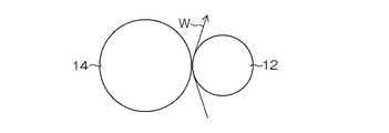
FIG. 1 is a side view of a web foreign
図1及び図2に示すように、バックアップローラ12、クリーニングローラ14、及び粘着ローラ16の3本のローラは、ローラの軸芯高さ位置を同じにして平行に配置される。
As shown in FIGS. 1 and 2, the three rollers of the
バックアップローラ12は、第1の移動テーブル18上に固定されたローラ支持台20上に対向配置された一対の軸受22、22に回転自在に支持される。第1の移動テーブル18は、基台24上に敷設された平行な一対の第1レール26、26上にリニアガイド28、28を介してスライド自在に支持される。また、基台24上には、第1の移動テーブル18を第1レール26上で移動させる一対の第1のシリンダ装置30、30が設けられ、それぞれのピストンロッド30A、30A先端が第1の移動テーブル18に固着される。
The
バックアップローラ12は、金属で形成されたローラ芯に、金属製又は樹脂製のローラ胴部を設けたローラとして形成される。金属製の場合ローラ表面には例えばニッケル・クロムメッキ等の硬質化処理が施されることが好ましい。また、樹脂製の場合には、硬質性樹脂を使用することが好ましい。なお、バックアップローラ12は、金属製や樹脂製に限らずローラ胴部が硬質材料で形成されているものを使用できる。
The
クリーニングローラ14は、第2の移動テーブル32上に固定されたローラ支持台34上に対向配置された一対の軸受36、36に回転自在に支持される。第2の移動テーブル32は、基台24上に敷設された平行な一対の第2レール38、38上にリニアガイド40、40を介してスライド自在に支持される。また、基台24上には、第2の移動テーブル32を第2レール38上で移動させる一対の第2のシリンダ装置42、42が設けられ、それぞれのピストンロッド42A,42A先端が第2の移動テーブル32に固着される。また、第2のシリンダ装置42、42は第1のシリンダ装置30、30に対向して配置される。
The cleaning
クリーニングローラ14は、金属で形成されたローラ芯に、粘着性を有するゴム製のローラ胴部を設けたゴムローラとして形成される。クリーニングローラ14のローラ表面の粘着力としては、1〜60(hPa)の範囲であることが好ましい。また、ローラ胴部のゴム硬度としては、20°〜60°の範囲が好ましい。
The cleaning
クリーニングローラ14のゴム硬度の測定方法は、スプリング式A型(JIS K 6301A)に準拠した方法であり、デューロメータAでの測定数値と同じになる。
The method for measuring the rubber hardness of the cleaning
また、クリーニングローラ14のローラ表面の粘着力の測定方法は、JIS K 6256に準拠している。
The method for measuring the adhesive force on the roller surface of the cleaning
粘着ローラ16は、第3の移動テーブル44上に固定されたローラ支持台46上に対向配置された一対の軸受48、48に回転自在に支持される。第3の移動テーブル44は、第2の移動テーブル32上に敷設された平行な一対の第3レール50、50上にリニアガイド52、52を介してスライド自在に支持される。また、第2の移動テーブル32上には、第3の移動テーブル44を第3レール50上で移動させる一対の第3のシリンダ装置54、54が設けられ、それぞれのピストンロッド54A,54A先端が第3の移動テーブル44に固着される。また、第3のシリンダ装置54、54は第2のシリンダ装置42、42と同方向を向いて配置される。
The
粘着ローラ16は、金属製のローラ芯に、クリーニングローラのゴム製のローラ胴部よりも粘着性の大きな粘着剤層を有するローラとして形成される。粘着剤層は、クリーニングローラよりも粘着性の大きなゴムで形成してもよく、あるいは金属製のローラ芯に、粘着テープを巻回した粘着テープロールであってもよい。粘着剤層の粘着力としては、JIS K 6256の測定方法において50〜400(hPa)の範囲であることが好ましい。
The
バックアップローラ12、クリーニングローラ14、及び粘着ローラ16のローラ面長は、ウエブWの幅よりも長く形成される。例えば、ローラ面長はウエブWの幅よりも100〜200mm程度長くすることが好ましい。また、バックアップローラ12、クリーニングローラ14、及び粘着ローラ16のうち、少なくともバックアップローラ12及びクリーニングローラ14は軸芯方向の撓み量が100μm以下、好ましくは50μm以下の低撓みローラを使用することが好ましい。
The roller surface lengths of the
低撓みローラとしては、撓み量が100μm以下であれば特に限定されないが、例えば、三菱樹脂(株)製の「二重管低たわみロール」や「カーボンロール」を使用することができる。「二重管低たわみロール」と「カーボンロール」とを使用する場合には、バックアップローラ12に「カーボンロール」を使用し、クリーニングローラ14に「二重管低たわみロール」を使用することが好ましい。
The low deflection roller is not particularly limited as long as the deflection amount is 100 μm or less. For example, a “double pipe low deflection roll” or “carbon roll” manufactured by Mitsubishi Plastics, Inc. can be used. When using a “double pipe low deflection roll” and a “carbon roll”, a “carbon roll” may be used as the
また、異物除去装置10には、クリーニングローラ14のローラ中央部の回転周速V1を測定する中央部周速測定手段56Aと、バックアップローラ12のローラ端部の回転周速V2を測定する端部周速測定手段56Bと、ローラ中央部とローラ端部との測定値に基づいて、[(V2−V1)/V1]×100で示す周速差率を調整する周速差率調整手段58(58A,58B)と、が設けられる。
Further, the foreign
ここで、本発明は、クリーニングローラ14のローラ中央部とローラ端部との周速差を問題としていながら、バックアップローラ12のローラ端部の回転周速V2を測定する理由について説明する。
Here, the present invention will explain the reason for measuring the rotational peripheral speed V2 at the roller end of the
即ち、クリーニングローラ14が撓んだ際にゴム製のクリーニングローラ14の両端部が強くバックアップローラ12の両端部に押し付けられて変形するため、正確な回転周速を測定できない。更には、バックアップローラ12のローラ両端部の回転周速がクリーニングローラ14のローラ両端部の回転周速V2と見做すことができるからである。
That is, when the cleaning
このため、図2に示すように、ローラ中央部の回転周速V1はクリーニングローラ14の中央部に中央部周速測定手段56Aに設置する一方、ローラ端部の回転周速V2についてはバックアップローラ12の両端部に端部周速測定手段56Bを設置して測定した。
Therefore, as shown in FIG. 2, the rotational peripheral speed V1 at the central portion of the roller is installed in the central peripheral speed measuring means 56A at the central portion of the cleaning
バックアップローラ12のローラ端部の回転周速がクリーニングローラ14のローラ両端部の回転周速V2と見做すことができることは後記するメカニズムを参照頂きたい。
For the rotational peripheral speed at the roller end of the
中央部周速測定手段56A及び端部周速測定手段56Bは、非接触の測定手段を使用することが好ましい。非接触の測定手段としては、例えばレーザードップラー速度計でローラ周速を測定するものを好適に採用できる。図2では、端部周速測定手段56Bを、バックアップローラ12の両端部にそれぞれ設けたが、一端側のみに設けてよい。バックアップローラ12のローラ両端部の回転周速が同じとして説明するが、仮に異なる場合には、端部周速測定手段56Bを、バックアップローラ12の両端部にそれぞれ設け、回転周速の大きい方のローラ端部の回転周速をV2とする。
It is preferable to use a non-contact measuring means for the central peripheral speed measuring means 56A and the end peripheral speed measuring means 56B. As the non-contact measuring means, for example, a means for measuring the roller peripheral speed with a laser Doppler velocimeter can be suitably employed. In FIG. 2, the end peripheral speed measuring means 56 </ b> B is provided at both ends of the
中央部周速測定手段56A及び端部周速測定手段56Bで測定された回転周速V1,V2は、信号ケーブルを介してコントローラ60に送られる。
The rotational peripheral speeds V1 and V2 measured by the central peripheral speed measuring means 56A and the end peripheral speed measuring means 56B are sent to the
また、周速差率調整手段58としては、ラップ角調整手段58Aとニップ圧調整手段58Bと、を好適に採用することができる。 Further, as the peripheral speed difference rate adjusting means 58, a lap angle adjusting means 58A and a nip pressure adjusting means 58B can be suitably employed.
ラップ角調整手段58Aは、バックアップローラ12に巻き掛け支持されるウエブWのラップ角(巻き掛け角度)を調整するものであり、ウエブ搬送方向におけるバックアップローラ12の入口側、出口側の何れに設けてもよいが、出口側がより好ましい。
The wrap angle adjusting means 58A adjusts the wrap angle (winding angle) of the web W that is wound around and supported by the
図3に示すように、ラップ角(θ)は、ウエブWがバックアップローラ12に接触し始める接点Xと、接触が終了する接点Yとが成す中心角をいう。
As shown in FIG. 3, the wrap angle (θ) refers to a central angle formed by the contact X at which the web W starts to contact the
ラップ角調整手段58Aは、図1に示すように、バックアップローラ12とガイドローラ61との間のウエブ搬送ライン上に、ウエブWに係合する係合ローラ62が設けられる。ウエブWはバックアップローラ12、係合ローラ62、ガイドローラ61との間にS字状に掛け渡される。係合ローラ62の回転軸両端は、ウエブWの幅方向に配設された一対のシリンダ装置63、63のロッド64、64に回転自在に支持される。これにより、シリンダ装置63、63がロッド64、64を伸縮させることによって、ウエブWのラップ角(θ)を可変することができる。
As shown in FIG. 1, the wrap angle adjusting means 58 </ b> A is provided with an engagement roller 62 that engages with the web W on a web conveyance line between the
ニップ圧調整手段58Bは、ウエブWをバックアップローラ12とクリーニングローラ14との間でニップ圧を調整するものであり、第2シリンダ装置42が信号ケーブルを介してコントローラ60に接続されることによって構成される。即ち、コントローラ60からの指示により、第2シリンダ装置42におけるピストンロッドの伸長量が制御され、これによりニップ圧が調整される。なお、第1のシリンダ装置30はバックアップローラ12の着脱を行うものである。第3のシリンダ装置54は、クリーニングローラ14と粘着ローラ16との間のニップ圧を調整するものである。これら第1のシリンダ装置30及び第3のシリンダ装置54の制御は、コントローラ60で兼用してもよく、別のコントローラを設けてもよい。
The nip pressure adjusting means 58B adjusts the nip pressure between the
次に、上記の如く構成された異物除去装置10を使用してウエブWの面に付着する異物を除去する異物除去方法を説明する。
Next, a foreign matter removing method for removing foreign matter adhering to the surface of the web W using the foreign
第1のシリンダ装置30と第2のシリンダ装置42のピストンロッド30A,42Aを伸び動作させることによって、バックアップローラ12に巻き掛け支持されて搬送されるウエブWをニップする。これにより、ウエブWの面に付着している塵埃等の異物がクリーニングローラ14に転写除去される。
By extending the
また、第3のシリンダ装置54のピストンロッド54Aを伸び動作させることによって、粘着ローラ16がクリーニングローラ14に押圧するので、クリーニングローラ14に転写された異物が粘着ローラ16に更に転写して除去される。これにより、搬送されるウエブWの面の異物を連続して除去することができる。
Further, by causing the
かかる異物除去において、中央部周速測定手段56A及び端部周速測定手段56Bによりクリーニングローラ14のローラ中央部の回転周速V1とバックアップローラ12のローラ端部の回転周速V2とが逐次測定され、測定値がコントローラ60に逐次送られる。コントローラ60は、測定された回転周速V1、V2から[(V2−V1)/V1]×100で示される周速差率を演算して、周速差率が0.5%以下であるか否かを判断する。
In such foreign matter removal, the rotation peripheral speed V1 at the center of the cleaning
そして、コントローラ60は、周速差率が0.5%以下であれば、異物除去装置10をそのまま運転する。また、コントローラ60は、周速差率が0.5%を超えている場合には、ラップ角調整手段58A及びニップ圧調整手段58Bの少なくとも1つを制御して、周速差率が0.5%以下になるようにする。即ち、ラップ角調整手段58Aにより、バックアップローラ12に巻き掛けられるウエブWのラップ角(θ)を例えば20°以下になるように小さくする。また、ニップ圧調整手段58Bを調整して、ニップ圧が例えば0.5N/cm以上、1.0N/cm以下になるように調整する。
And if the peripheral speed difference rate is 0.5% or less, the
これにより、周速差率が0.5%以下になるので、粘着ゴムローラ方式のウエブ異物除去において、異物の除去効率が良く、且つウエブWの裏面(塗布膜を有しない面)にウエブ走行方向に沿ってスジ状の擦り傷P(図4参照)が発生したり、発塵したりすることを効果的に抑制できる。 As a result, the peripheral speed difference ratio becomes 0.5% or less, so that the removal efficiency of the foreign matter is good in removing the web foreign matter by the adhesive rubber roller method, and the web running direction is on the back surface (the surface not having the coating film) of the web W. It is possible to effectively suppress the generation of streak-like scratches P (see FIG. 4) and the generation of dust.
ここで、ウエブWのテンションの大小やニップ圧の大小によって、クリーニングローラ14の中央部周速と端部周速との間で周速差が生じるメカニズムを説明する。
Here, a mechanism in which a difference in peripheral speed between the central peripheral speed and the end peripheral speed of the cleaning
図5は、ウエブWのテンションによってバックアップローラ12が弓なりに撓んだ状態を過剰に表現したものである。また、図6は、図5に示すバックアップローラ12のローラ中央部をa−a線に沿って切断した断面図であり、図7(A)はローラ端部をb−b線に沿って切断した断面図である。
FIG. 5 excessively represents the state in which the
図5のようにウエブWのテンションによってバックアップローラ12が撓むと、クリーニングローラ14のローラ中央部はニップ圧が弱まる方向に作用する。したがって、図6に示すようにクリーニングローラ14のローラ中央部は変形が少ない。また、クリーニングローラ14のローラ中央部はウエブWと接触しており、粘着性を有してウエブWに対するグリップ力が大きいので、ウエブWの搬送速度と同速度で回転する。
When the
一方、ウエブWの幅よりもローラ面長の長いクリーニングローラ14の両端部は、ウエブWを介さずにバックアップローラ12に直接接触する。また、撓んだバックアップローラ12によってニップ圧が強まる方向に作用するので、クリーニングローラ14のローラ両端部は変形が大きくなる。
On the other hand, both end portions of the cleaning
図7(B)は、クリーニングローラ14のローラ端部とバックアップローラ12との接触部分の拡大図である。図7(B)に示すように、バックアップローラ12よりも軟らかいゴム製のクリーニングローラ14(斜線で示す)のローラ端部は、B1−B2で示す部分で凹状に変形する。更には、凹状の両端がバックアップローラ12に僅かに被さるので、結局、クリーニングローラ14のローラ端部はバックアップローラ12に対してA1−A2の部分で凹状に接触する。そして、A1−A2で示す凹状の長さはB1−B2で示す凹状の長さよりも大きくなるので、クリーニングローラ14のローラ端部の回転周速は、ローラ中央部の回転周速よりも大きくなる。
FIG. 7B is an enlarged view of a contact portion between the roller end of the cleaning
また、クリーニングローラ14のローラ両端部はバックアップローラ12のローラ両端部に直接接触してグリップするので、クリーニングローラ14の両端部の回転周速と同じ回転周速でバックアップローラ12を回転させることになる。即ち、上記したように、バックアップローラ12のローラ端部の回転周速V2がクリーニングローラ14のローラ端部の回転周速と見做すことができる。
Further, since both ends of the roller of the cleaning
この結果、ウエブWの搬送速度よりもバックアップローラ12の回転周速が大きくなり、バックアップローラ12とウエブWとがスリップする。
As a result, the rotational peripheral speed of the
これにより、図4に示したように、ウエブWの裏面に付着している塵埃等の異物によってウエブWの裏面にウエブ搬送方向に沿った擦り傷Pが生じる。例えば、1%のスリップによって約200μmの擦り傷が発生する。また、スリップによって発塵し易くなる。 As a result, as shown in FIG. 4, scratches P along the web conveyance direction are generated on the back surface of the web W due to foreign matters such as dust adhering to the back surface of the web W. For example, a 1% slip causes a scratch of about 200 μm. Moreover, it becomes easy to generate | occur | produce dust by slip.
また、バックアップローラ12の撓みによって、クリーニングローラ14のローラ中央部におけるニップ圧が弱くなることによって、異物除去効率も低下する。
In addition, the nip pressure at the central portion of the cleaning
なお、上記説明したメカニズムは、ウエブWのテンションによってバックアップローラ12が撓むことにより、クリーニングローラ14のローラ中央部とローラ端部とで周速差が生じる場合である。しかし、ニップ圧によってバックアップローラ12やクリーニングローラ14が撓む場合も同様のメカニズムにより、クリーニングローラ14のローラ中央部とローラ端部とで周速差が生じる。
Note that the mechanism described above is a case where a peripheral speed difference is generated between the central portion of the cleaning
そこで、本発明者は、クリーニングローラ14のローラ中央部の回転周速V1と、バックアップローラ12のローラ両端部の回転周速V2、換言するとクリーニングローラ14のローラ両端部の回転周速との差がどの程度まで許容されるかを鋭意研究した結果、[(V2−V1)/V1]×100で示される周速差率が0.5%以下であれば、異物除去性能、擦り傷及び発塵の抑制において実用上問題ないことが分かった。
Therefore, the present inventor has found that the difference between the rotational peripheral speed V1 at the center of the cleaning
そして、以下の3つの方法の少なくとも1つを実施することで、周速差率が0.5%以下を達成することができる。 Then, by implementing at least one of the following three methods, the peripheral speed difference rate can be 0.5% or less.
(1)バックアップローラ12、クリーニングローラ14、及び粘着ローラ16のうち、少なくともバックアップローラ12及びクリーニングローラ14の軸芯方向の撓み量が50μm以下の低撓みローラを用いる。
(1) Of the
(2)ラップ角調整手段58Aによりバックアップローラ12に巻き掛け支持されるウエブWのラップ角(θ)を調整する。
(2) The wrap angle adjusting means 58A adjusts the wrap angle (θ) of the web W that is wound around and supported by the
図8は、バックアップローラ12に巻き掛けるウエブWのラップ角(θ)及びウエブテンションと、バックアップローラ12のローラ撓み量(μm)との関係を示したものである。図6から分かるように、同じウエブテンションでは、ラップ角(θ)が大きくなるほどバックアップローラ12のローラ撓み量が大きくなる。したがって、ラップ角調整手段58Aによりバックアップローラ12に巻き掛け支持されるウエブWのラップ角(θ)を小さくすることで、バックアップローラ12のローラ撓み量を小さくできる。これにより、上記説明したメカニズムから、クリーニングローラ14の周速差率を小さくすることができる。ラップ角(θ)としては20°以下にすることが好ましい。
FIG. 8 shows the relationship between the wrap angle (θ) and web tension of the web W wound around the
(3)ニップ圧調整手段58Bにより、バックアップローラ12とクリーニングローラ14との間のニップ圧を調整する。
(3) The nip pressure between the
図9は、ニップ圧(N/cm)とバックアップローラ12の回転周速との関係を示したものである。図9の三角で示すポイントを繋いだ線がバックアップローラ12の回転周速(m/min)である。また、四角で示すポイントを繋いだ線がウエブWを搬送するパスローラの回転周速(m/min)であり、ウエブWの搬送速度に相当する。
FIG. 9 shows the relationship between the nip pressure (N / cm) and the rotational peripheral speed of the
ニップ圧を大きくしていくと、上記説明したメカニズムからクリーニングローラ14のローラ端部の回転周速が大きくなり、それに追従してバックアップローラ12の回転周速が大きくなる。
As the nip pressure increases, the rotational peripheral speed of the roller end of the cleaning
したがって、ニップ圧調整手段58Bによりバックアップローラ12とクリーニングローラ14とのニップ圧を小さくすることで、上記説明したメカニズムから、クリーニングローラ14の周速差率を小さくすることができる。ニップ圧としては0.5N/cm以上、1.0N/cm以下にすることが好ましい。
Therefore, by reducing the nip pressure between the
本発明の実施の形態で説明したウエブの異物除去方法及び異物除去装置について、具体的に試験を行った結果を説明する。 The results of specific tests on the foreign matter removal method and foreign matter removal apparatus described in the embodiment of the present invention will be described.
[異物除去装置の条件]
〈ウエブ〉
・種類…セルローストリアセテートフィルム(TAC)
・幅…1490mm
・搬送速度…100m/分
・搬送テンション…350N
〈バックアップローラ〉
・ローラ面長…1650mm
・ローラ径…110mm
・種類…金属製ローラ
・撓み量が約600μmのアルミ管式のバックアップローラと、撓み量が約50μmの低撓み式のバックアップローラと、の2種類を使用した。
[Conditions for foreign material removal equipment]
<Web>
・ Type: Cellulose triacetate film (TAC)
・ Width: 1490mm
・ Conveyance speed: 100 m / min ・ Conveyance tension: 350 N
<Backup roller>
・ Roller surface length: 1650mm
・ Roller diameter ... 110mm
・ Type: Metal roller ・ Two types were used: an aluminum tube type backup roller with a deflection amount of about 600 μm and a low deflection type backup roller with a deflection amount of about 50 μm.
〈クリーニングローラ〉
・ローラ面長…1650mm
・ローラ径…110mm
・種類…粘着性ゴムローラ
・ゴム硬度…35°
・粘着力…10hPa
・撓み量が約600μmのアルミ管式のクリーニングローラと、撓み量が約50μmの低撓み式のクリーニングローラと、の2種類を使用した。
<Cleaning roller>
・ Roller surface length: 1650mm
・ Roller diameter ... 110mm
・ Type: Adhesive rubber roller ・ Rubber hardness: 35 °
・ Adhesive strength: 10 hPa
Two types, an aluminum tube type cleaning roller with a deflection amount of about 600 μm and a low deflection type cleaning roller with a deflection amount of about 50 μm, were used.
〈粘着ローラ〉
・ローラ面長…1650mm
・ローラ径…100mm
・種類…粘着性ゴムローラ
・粘着力…90hPa
・撓み量が約600μmのアルミ管式の粘着ローラと、撓み量が約50μmの低撓み式の粘着ローラと、の2種類を使用した。
<Adhesive roller>
・ Roller surface length: 1650mm
・ Roller diameter ... 100mm
・ Type: Adhesive rubber roller ・ Adhesive strength: 90 hPa
Two types were used: an aluminum tube type adhesive roller with a deflection amount of about 600 μm and a low deflection type adhesive roller with a deflection amount of about 50 μm.
〈備考〉
・図10の表には、バックアップローラを「BUR」、クリーニングローラを「CLR」、粘着ローラを「粘着R」と表示している。
<Remarks>
In the table of FIG. 10, the backup roller is indicated as “BUR”, the cleaning roller as “CLR”, and the adhesive roller as “adhesive R”.
・図10の表の「ローラ撓み量」において、バックアップローラと、クリーニングローラ及び粘着ローラとの撓む方向が逆なので、バックアップローラの撓み量には「−」を付した。 In the “roller deflection amount” in the table of FIG. 10, since the deflection directions of the backup roller, the cleaning roller, and the adhesive roller are opposite, “−” is given to the deflection amount of the backup roller.
・図10の表の「中央部周速」はクリーニングローラ(CLR)で測定した周速(V1)であり、「端部周速」はバックアップローラ(BUR)で測定した周速(V2)である。 In the table of FIG. 10, the “central peripheral speed” is the peripheral speed (V1) measured with the cleaning roller (CLR), and the “end peripheral speed” is the peripheral speed (V2) measured with the backup roller (BUR). is there.
・図10の表の「ローラ撓み量」は、ローラ中央部、ローラ両端部にそれぞれレーザ変位計を配置して測定した。 The “roller deflection amount” in the table of FIG. 10 was measured by placing laser displacement meters at the center of the roller and at both ends of the roller.
[評価項目]
〈除塵性能の評価方法〉
ウエブの一方面に光源から光を当てると共に、他方面にCCDカメラを配置した透過型の面検装置を使用した。そして、クリーニングローラによる除塵前のウエブ単位m当りの異物個数(10μm以上の異物)をAとし、クリーニングローラによる除塵後のウエブ単位m当りの異物個数(10μm以上の異物)をBとしたときの下記式で示される除塵率で評価した。
[Evaluation item]
<Dust removal performance evaluation method>
A transmission type surface inspection device was used in which light from a light source was applied to one side of the web and a CCD camera was placed on the other side. When A is the number of foreign matters per unit of web (10 μm or more) before dust removal by the cleaning roller, and B is the number of foreign matters per unit of web after dust removal by the cleaning roller (10 μm or more). The dust removal rate represented by the following formula was evaluated.
除塵率(%)=[1−(B/A)]×100
〈ウエブ裏面の擦り傷の評価方法〉
ウエブの片面に光源から光を当てると共に、光源と同じ片面にCCDカメラを配置した反射型の面検装置を使用した。
Dust removal rate (%) = [1- (B / A)] × 100
<Evaluation method of scratches on the back of the web>
A reflection type surface inspection device was used in which light from a light source was applied to one side of the web and a CCD camera was placed on the same side as the light source.
そして、クリーニングローラによる除塵前のウエブ単位m当りの傷個数(50μm以上の傷)をCとし、クリーニングローラによる除塵後のウエブ単位面積当りの傷個数(50μm以上の傷)をDとしたときの下記式で示される傷発生個数で評価した。 The number of scratches per unit of web (must be 50 μm or more) before dust removal by the cleaning roller is C, and the number of scratches per unit area of the web after dust removal by the cleaning roller is D (scratches of 50 μm or more). Evaluation was made based on the number of scratches represented by the following formula.
傷発生個数=D−C(個/m)
〈評価の方法〉
*A…除塵性能を示す除塵率が60%以上、ウエブ裏面の傷発生個数が0.001個/m未満の場合で「非常に良い」を意味する。
Number of scratches generated = DC (pieces / m)
<Method of evaluation>
* A: When the dust removal rate indicating dust removal performance is 60% or more and the number of scratches on the back of the web is less than 0.001 / m, it means “very good”.
*B…除塵性能を示す除塵率が40%以上〜60%未満、ウエブ裏面の傷発生個数が0.001個/m以上〜0.01個/m未満の場合で「良い」を意味する。 * B: Means “good” when the dust removal rate indicating the dust removal performance is 40% to less than 60% and the number of scratches on the back surface of the web is 0.001 piece / m to less than 0.01 piece / m.
*C…除塵性能を示す除塵率が40%未満、ウエブ裏面の傷発生個数が0.01個/m以上の場合で「悪い」を意味する。 * C: When the dust removal rate indicating dust removal performance is less than 40% and the number of scratches on the back of the web is 0.01 / m or more, it means “bad”.
[試験結果]
図10の表の試験1〜4の比較から分かるように、バックアップローラ、クリーニングローラ、粘着ローラともアルミ管式のローラを使用し、ニップ圧を2.0N/cmに固定した場合、バックアップローラに対するウエブのラップ角を変えることでバックアップローラの撓み量は変化する。
[Test results]
As can be seen from the comparison of
また、試験5〜8の比較から分かるように、バックアップローラを低撓みのローラに変えることで、試験1〜4に比べて、バックアップローラの撓み量は100μm以下まで減少する。
Further, as can be seen from the comparison of
しかし、試験1〜8は、ニップ圧が2.0N/cmと大きく、クリーニングローラの撓み量が100μmと大きいために、クリーニングローラの周速差率は1〜2%と高い。即ち周速差率が本発明を満足する0.5%以下にならない。この結果、異物除去性能は「C」〜「B」の評価であると共に、ウエブ裏面の擦り傷も全て「C」の評価であり、総合評価も「C」であった。
However, in
これに対して、試験9は、試験8のニップ圧を1.0N/cmまで小さくした場合であり、クリーニングローラの撓み量が50μmまで小さくなる。これにより、クリーニングローラの周速差率は0.5%となり、本発明を満足する。この結果、試験9の異物除去性能は「A」の評価であると共に、ウエブ裏面の擦り傷も全て「B」の評価となり、総合評価は「B」であった。
On the other hand,
また、試験10、11は、バックアップローラとクリーニングローラの2本のローラを低撓みローラとすると共に、ラップ角を20°に固定して、ニップ圧を2.0N/cmと1.0N/cmの2水準で行った場合である。この結果、バックアップローラ及びクリーニングローラともに撓み量が小さくなり、クリーニングローラの周速差率も試験10では0.1%、試験11では0.0%と小さくなった。これにより、試験10は異物除去性能が「A」、ウエブ裏面の擦り傷が「B」で総合評価も「B」となった。更に、試験11は異物除去性能、ウエブ裏面の擦り傷、総合評価ともに「A」の評価であった。
In
また、試験12、13は、バックアップローラ、クリーニングローラ、粘着ローラの3本のローラを低撓みローラとすると共に、ラップ角を20°に固定して、ニップ圧を2.0N/cmと1.0N/cmの2水準で行った場合である。この結果、バックアップローラ、クリーニングローラ、粘着ローラともに撓み量が小さくなり、クリーニングローラの周速差率も試験12では0.1%、試験13では0.0%と小さくなった。これにより、試験12は異物除去性能が「A」、ウエブ裏面の擦り傷が「B」で総合評価も「B」となった。更に、試験13は異物除去性能、ウエブ裏面の擦り傷、総合評価ともに「B」の評価であった。
In
また、試験14、15は、バックアップローラ、クリーニングローラ、粘着ローラの3本のローラを低撓みローラとすると共に、ラップ角を20°に固定して、ニップ圧を0.5N/cmと0.3N/cmの2水準で行った場合である。この結果、ニップ圧を0.5N/cmの場合には、バックアップローラ、クリーニングローラ、粘着ローラともに撓み量が小さくなり、クリーニングローラの周速差率も試験14では0.0%となった。これにより、試験14は異物除去性能が「A」、ウエブ裏面の擦り傷が「A」で総合評価も「A」となった。
In
これに対して、試験15のようにニップ圧を0.3N/cmにした場合には、バックアップローラ、クリーニングローラ、粘着ローラの3本のローラの撓み量は小さくなるものの、バックアップローラの端部周速がクリーニングローラの中央部周速よりも小さくなってしまった。これにより、試験15は異物除去性能が「B」であるものの、ウエブ裏面の擦り傷が「C」となり、総合評価も「C」となった。
On the other hand, when the nip pressure is set to 0.3 N / cm as in
これにより、ニップ圧を0.5N/cm以上、1.0N/cm以下に調整することで、
バックアップローラのローラ中央部とローラ端部との周速差が一層小さくなり、異物除去性能を向上できる一方、ウエブ裏面への傷発生をより効果的に防止できることが分かる。
Thereby, by adjusting the nip pressure to 0.5 N / cm or more and 1.0 N / cm or less,
It can be seen that the peripheral speed difference between the roller center portion and the roller end portion of the backup roller is further reduced, and the foreign matter removal performance can be improved, while the occurrence of scratches on the back surface of the web can be more effectively prevented.
また、評価項目として「発塵」の記載はないが、クリーニングローラの周速差率を0.5%以下にすることで、「発塵」も効果的に抑制できた。 Although “dust generation” is not described as an evaluation item, “dust generation” can be effectively suppressed by setting the peripheral speed difference rate of the cleaning roller to 0.5% or less.
上記実施例の結果から、バックアップローラに巻き掛け支持されるウエブのラップ角度、及びバックアップローラとクリーニングローラとのニップ圧を調整することで、クリーニングローラの周速差率を0.5%以下にすることができる。 From the result of the above embodiment, the peripheral speed difference rate of the cleaning roller is reduced to 0.5% or less by adjusting the wrap angle of the web that is wound around and supported by the backup roller, and the nip pressure between the backup roller and the cleaning roller. can do.
また、試験1〜15の結果から、異物除去性能、ウエブ裏面の擦り傷、及び総合評価の全てが「A」の評価となったのは、周速差率が0.0%の場合であり、周速差率0.0%がベストモードと言える。
In addition, from the results of
この場合、バックアップローラ、クリーニングローラ、粘性ローラのうちの少なくともバックアップローラとクリーニングローラに低撓みローラを使用することで、一層良い結果を得ることができる。 In this case, a better result can be obtained by using a low deflection roller for at least the backup roller and the cleaning roller among the backup roller, the cleaning roller, and the viscous roller.
しかし、光学フィルムの幅は、大サイズの液晶表示装置への適用や歩留り向上のため拡大化傾向にあるため、使用されるバックアップローラ、クリーニングローラ、粘着ローラのローラ面長も長くなり、撓み易くなる。また、光学フィルムの製造ライン配置からバックアップローラに巻き掛けるラップ角度も大きくならざるをえない場合がある。 However, the width of the optical film tends to be expanded for application to large-sized liquid crystal display devices and yield improvement, so the length of the roller surface of the backup roller, cleaning roller, and adhesive roller used is also long and is easily bent. Become. Further, there is a case where the wrap angle wound around the backup roller is inevitably increased due to the arrangement of the optical film production line.
したがって、バックアップローラ、クリーニングローラ、及び粘着ローラのうち、少なくともバックアップローラ及びクリーニングローラの軸芯方向の撓み量が50μm以下の低撓みローラを用い、且つラップ角調整手段及びニップ圧調整手段でラップ角やニップ圧を調整することで、クリーニングローラの周速差率を0.5%以下にすることが好ましい。 Therefore, among the backup roller, the cleaning roller, and the adhesive roller, at least the backup roller and the cleaning roller have a low deflection roller whose deflection in the axial direction is 50 μm or less, and the wrap angle is adjusted by the wrap angle adjusting unit and the nip pressure adjusting unit. It is preferable to adjust the peripheral speed difference rate of the cleaning roller to 0.5% or less by adjusting the nip pressure.
10…異物除去装置、12…バックアップローラ、14…クリーニングローラ、16…粘着ローラ、18…第1の移動テーブル、20…ローラ支持台、22…軸受、24…基台、26…第1レール、28…リニアガイド、30…第1のシリンダ装置、32…第2の移動テーブル、34…ローラ支持台、36…軸受、38…第2レール、40…リニアガイド、42…第2のシリンダ装置、44…第3の移動テーブル、46…ローラ支持台、48…軸受、50…第3レール、52…リニアガイド、54…第3のシリンダ装置、56A…中央部周速測定手段、56B…端部周速測定手段、58…周速差率調整手段、58A…ラップ角調整手段、58B…ニップ圧調整手段、60…コントローラ、61…ガイドローラ、62…係合ローラ、63…シリンダ装置、64…ロッド
DESCRIPTION OF
Claims (8)
前記クリーニングローラのローラ中央部の回転周速をV1(m/min)とし、前記バックアップローラのローラ端部の回転周速をV2(m/min)としたときに、[(V2−V1)/V1]×100で示す周速差率が0.5%以下を満足するように、前記バックアップローラに巻き掛けられる前記ウエブのラップ角度を調整する方法と前記ウエブを前記バックアップローラと前記クリーニングローラとの間にニップするニップ圧を調整する方法の少なくとも1つの方法を行うウエブの異物除去方法。 A cleaning roller having a roller peripheral surface having adhesive rubber is nipped through a metal or resin backup roller that is wound and supported by the web to be conveyed and is rotated by the conveyance of the web. In the method for removing foreign matter on the web, which is transferred and removed to the cleaning roller for removing foreign matter adhering to the surface of the web,
When the rotational peripheral speed at the roller central portion of the cleaning roller is V1 (m / min) and the rotational peripheral speed at the roller end of the backup roller is V2 (m / min), [(V2-V1) / V1] × 100 and a method for adjusting the wrap angle of the web wound around the backup roller so that the peripheral speed difference ratio satisfies 0.5% or less, and the web as the backup roller and the cleaning roller. A method for removing foreign matter from a web, wherein at least one of the methods for adjusting the nip pressure during nip is adjusted .
前記ウエブを前記バックアップローラとの間にニップして前記ウエブの表面に付着している異物を、粘着性ゴムを有するローラ周面に転写除去すると共に前記ウエブの搬送によって従動回転するクリーニングローラと、
前記クリーニングローラのローラ中央部の回転周速V1を測定する中央部周速測定手段と、
前記バックアップローラのローラ端部の回転周速V2を測定する端部周速測定手段と、
前記ローラ中央部と前記ローラ端部との測定値に基づいて、[(V2−V1)/V1]×100で示す周速差率を調整する周速差率調整手段と、を備え、
前記周速差率調整手段は、前記バックアップローラに巻き掛けられる前記ウエブのラップ角度を調整するラップ角調整手段と、前記ウエブを前記バックアップローラと前記クリーニングローラとの間にニップするニップ圧を調整するニップ圧調整手段と、の少なくとも1つであるウエブの異物除去装置。 A metal or resin backup roller that is supported by wrapping and supporting the web to be conveyed and rotated by the conveyance of the web;
A cleaning roller that nips the web between the backup roller and adheres to the surface of the web by transferring and removing the foreign material to the roller peripheral surface having an adhesive rubber and being rotated by the conveyance of the web;
A central peripheral speed measuring means for measuring the rotational peripheral speed V1 of the central portion of the cleaning roller;
End peripheral speed measuring means for measuring the rotational peripheral speed V2 of the roller end of the backup roller;
A peripheral speed difference rate adjusting means for adjusting a peripheral speed difference rate indicated by [(V2−V1) / V1] × 100 based on measured values of the roller center portion and the roller end portion ;
The peripheral speed difference rate adjusting means adjusts a wrap angle adjusting means for adjusting a wrap angle of the web wound around the backup roller, and adjusts a nip pressure for nipping the web between the backup roller and the cleaning roller. And a nip pressure adjusting means for removing the foreign matter from the web.
Priority Applications (4)
| Application Number | Priority Date | Filing Date | Title |
|---|---|---|---|
| JP2012167476A JP5710552B2 (en) | 2012-07-27 | 2012-07-27 | Foreign matter removal method and foreign matter removal apparatus for web |
| KR1020130087938A KR20140013995A (en) | 2012-07-27 | 2013-07-25 | Method and apparatus for removing foreign material from web |
| CN201310316416.XA CN103567164B (en) | 2012-07-27 | 2013-07-25 | The foreign matter minimizing technology of lamellar and foreign matter removal device |
| TW102126943A TW201404482A (en) | 2012-07-27 | 2013-07-26 | Foreign matter removing method for thin slat strip and foreign matter removing device |
Applications Claiming Priority (1)
| Application Number | Priority Date | Filing Date | Title |
|---|---|---|---|
| JP2012167476A JP5710552B2 (en) | 2012-07-27 | 2012-07-27 | Foreign matter removal method and foreign matter removal apparatus for web |
Publications (3)
| Publication Number | Publication Date |
|---|---|
| JP2014024034A JP2014024034A (en) | 2014-02-06 |
| JP2014024034A5 JP2014024034A5 (en) | 2014-05-01 |
| JP5710552B2 true JP5710552B2 (en) | 2015-04-30 |
Family
ID=50040369
Family Applications (1)
| Application Number | Title | Priority Date | Filing Date |
|---|---|---|---|
| JP2012167476A Active JP5710552B2 (en) | 2012-07-27 | 2012-07-27 | Foreign matter removal method and foreign matter removal apparatus for web |
Country Status (4)
| Country | Link |
|---|---|
| JP (1) | JP5710552B2 (en) |
| KR (1) | KR20140013995A (en) |
| CN (1) | CN103567164B (en) |
| TW (1) | TW201404482A (en) |
Families Citing this family (5)
| Publication number | Priority date | Publication date | Assignee | Title |
|---|---|---|---|---|
| CN105151423A (en) * | 2015-08-11 | 2015-12-16 | 安徽远鸿机械自动化有限公司 | Dust adhering method used in thin film packaging process |
| KR102104297B1 (en) * | 2016-11-30 | 2020-04-24 | 주식회사 엘지화학 | Device of Cleaning Protect Film for Preparation of Battery Cell Comprising Cleaning Roll |
| CN106847083B (en) | 2017-03-20 | 2019-08-09 | 合肥鑫晟光电科技有限公司 | Foreign matter collection structure, display device and operating method thereof |
| CN114405936A (en) * | 2021-12-01 | 2022-04-29 | 西安泰金工业电化学技术有限公司 | A dust collector for ultra-thin copper foil surface |
| JP2024082712A (en) | 2022-12-09 | 2024-06-20 | コニカミノルタ株式会社 | Manufacturing method of film, information processing device, information processing system, information processing program and film |
Family Cites Families (9)
| Publication number | Priority date | Publication date | Assignee | Title |
|---|---|---|---|---|
| JP2928459B2 (en) * | 1994-05-31 | 1999-08-03 | アミテック株式会社 | Dust removal device |
| JPH0957218A (en) * | 1995-08-18 | 1997-03-04 | Kanegafuchi Chem Ind Co Ltd | Plastic film surface cleaning equipment |
| JPH0966259A (en) * | 1995-08-31 | 1997-03-11 | Fuji Photo Film Co Ltd | Drying device for belt |
| JPH1122720A (en) * | 1997-07-04 | 1999-01-26 | Toray Ind Inc | FRP roll |
| JP2000288483A (en) * | 1999-04-05 | 2000-10-17 | Fuji Photo Film Co Ltd | Dust removing method of long-length flexible sheet |
| JP2003171044A (en) * | 2001-12-04 | 2003-06-17 | Toppan Printing Co Ltd | Tension adjustment device |
| JP2004098588A (en) * | 2002-09-12 | 2004-04-02 | Fuji Photo Film Co Ltd | Processing method and marking apparatus for photographic sensitive material |
| JP2005081297A (en) * | 2003-09-10 | 2005-03-31 | Yodogawa Medekku Kk | Substrate surface cleaning apparatus |
| JP2006130500A (en) * | 2004-10-08 | 2006-05-25 | Showa Denko Kk | Method and apparatus for scrub cleaning |
-
2012
- 2012-07-27 JP JP2012167476A patent/JP5710552B2/en active Active
-
2013
- 2013-07-25 CN CN201310316416.XA patent/CN103567164B/en not_active Expired - Fee Related
- 2013-07-25 KR KR1020130087938A patent/KR20140013995A/en not_active Ceased
- 2013-07-26 TW TW102126943A patent/TW201404482A/en unknown
Also Published As
| Publication number | Publication date |
|---|---|
| KR20140013995A (en) | 2014-02-05 |
| JP2014024034A (en) | 2014-02-06 |
| TW201404482A (en) | 2014-02-01 |
| CN103567164B (en) | 2016-03-02 |
| CN103567164A (en) | 2014-02-12 |
Similar Documents
| Publication | Publication Date | Title |
|---|---|---|
| JP5710552B2 (en) | Foreign matter removal method and foreign matter removal apparatus for web | |
| JP5688858B2 (en) | Functional film manufacturing method and web transport device | |
| JP2012096989A (en) | Method and apparatus for guiding flexible glass ribbon | |
| US9802779B2 (en) | Methods and systems for preventing wrinkles in a web fed through an accumulator | |
| EP3237317B1 (en) | Edge contact substrate transport method and apparatus | |
| WO2011158584A1 (en) | Conveyance device and conveyance method for thin film glass | |
| CN103818756B (en) | Connect pressure roller and its manufacture method | |
| CN103424934B (en) | The manufacture method of rubbing treatment method and optical thin film | |
| WO2012114820A1 (en) | Method for producing film and apparatus for producing film | |
| JP4964630B2 (en) | Coating apparatus and coating method | |
| JP2008037653A (en) | Roller for transferring and stretching tape material | |
| US20110062274A1 (en) | Peel off device for unwinding a web of material from a roll | |
| TW201702645A (en) | Method for producing rubbed strip-shaped base material, and rubbing device | |
| JP2009241019A (en) | Coating method | |
| JP2014215494A (en) | Rubbing processing method and device | |
| JP4996273B2 (en) | Rubbing method and apparatus, and optical film manufacturing method and apparatus using the same | |
| JP2009136712A (en) | Application method and apparatus | |
| CN223128496U (en) | Coating equipment | |
| CN201971491U (en) | Constant-tension unreeling machine | |
| JP2001072291A (en) | Transport roll and method for transporting long objects using the same | |
| JP2014201401A (en) | Guide roll and web conveyance apparatus | |
| JP5324189B2 (en) | Thin paper roll winding length measuring device | |
| JP2000086031A (en) | Sheet conveying device and sheet manufacturing method | |
| US20200189870A1 (en) | Passive edge guiding method and apparatus | |
| JP2008185981A (en) | Rubbing method and apparatus, and optical film manufacturing method and apparatus using the same |
Legal Events
| Date | Code | Title | Description |
|---|---|---|---|
| A621 | Written request for application examination |
Free format text: JAPANESE INTERMEDIATE CODE: A621 Effective date: 20140225 |
|
| A521 | Request for written amendment filed |
Free format text: JAPANESE INTERMEDIATE CODE: A523 Effective date: 20140314 |
|
| A977 | Report on retrieval |
Free format text: JAPANESE INTERMEDIATE CODE: A971007 Effective date: 20140612 |
|
| A131 | Notification of reasons for refusal |
Free format text: JAPANESE INTERMEDIATE CODE: A131 Effective date: 20140620 |
|
| A521 | Request for written amendment filed |
Free format text: JAPANESE INTERMEDIATE CODE: A523 Effective date: 20140731 |
|
| TRDD | Decision of grant or rejection written | ||
| A01 | Written decision to grant a patent or to grant a registration (utility model) |
Free format text: JAPANESE INTERMEDIATE CODE: A01 Effective date: 20150220 |
|
| A61 | First payment of annual fees (during grant procedure) |
Free format text: JAPANESE INTERMEDIATE CODE: A61 Effective date: 20150304 |
|
| R150 | Certificate of patent or registration of utility model |
Ref document number: 5710552 Country of ref document: JP Free format text: JAPANESE INTERMEDIATE CODE: R150 |
|
| R250 | Receipt of annual fees |
Free format text: JAPANESE INTERMEDIATE CODE: R250 |
|
| R250 | Receipt of annual fees |
Free format text: JAPANESE INTERMEDIATE CODE: R250 |
|
| R250 | Receipt of annual fees |
Free format text: JAPANESE INTERMEDIATE CODE: R250 |
|
| R250 | Receipt of annual fees |
Free format text: JAPANESE INTERMEDIATE CODE: R250 |
|
| R250 | Receipt of annual fees |
Free format text: JAPANESE INTERMEDIATE CODE: R250 |
|
| R250 | Receipt of annual fees |
Free format text: JAPANESE INTERMEDIATE CODE: R250 |
|
| R250 | Receipt of annual fees |
Free format text: JAPANESE INTERMEDIATE CODE: R250 |
|
| R250 | Receipt of annual fees |
Free format text: JAPANESE INTERMEDIATE CODE: R250 |
|
| R250 | Receipt of annual fees |
Free format text: JAPANESE INTERMEDIATE CODE: R250 |