JP5691069B2 - Earth retaining wall of forestry road or forest work road and its construction method - Google Patents
Earth retaining wall of forestry road or forest work road and its construction method Download PDFInfo
- Publication number
- JP5691069B2 JP5691069B2 JP2010281852A JP2010281852A JP5691069B2 JP 5691069 B2 JP5691069 B2 JP 5691069B2 JP 2010281852 A JP2010281852 A JP 2010281852A JP 2010281852 A JP2010281852 A JP 2010281852A JP 5691069 B2 JP5691069 B2 JP 5691069B2
- Authority
- JP
- Japan
- Prior art keywords
- retaining wall
- road
- shaped
- forestry
- frame
- Prior art date
- Legal status (The legal status is an assumption and is not a legal conclusion. Google has not performed a legal analysis and makes no representation as to the accuracy of the status listed.)
- Active
Links
- 238000010276 construction Methods 0.000 title description 39
- 239000000463 material Substances 0.000 claims description 83
- XEEYBQQBJWHFJM-UHFFFAOYSA-N Iron Chemical compound [Fe] XEEYBQQBJWHFJM-UHFFFAOYSA-N 0.000 claims description 32
- 239000004576 sand Substances 0.000 claims description 24
- 229910052742 iron Inorganic materials 0.000 claims description 16
- 230000003014 reinforcing effect Effects 0.000 claims description 15
- 229910000831 Steel Inorganic materials 0.000 claims description 12
- 239000010959 steel Substances 0.000 claims description 12
- 239000004575 stone Substances 0.000 claims description 10
- 238000000034 method Methods 0.000 claims description 7
- 238000012856 packing Methods 0.000 claims description 6
- 238000005096 rolling process Methods 0.000 claims description 4
- 238000003466 welding Methods 0.000 claims description 4
- 238000005452 bending Methods 0.000 claims description 3
- XLYOFNOQVPJJNP-UHFFFAOYSA-N water Substances O XLYOFNOQVPJJNP-UHFFFAOYSA-N 0.000 description 6
- 230000035699 permeability Effects 0.000 description 5
- 238000009434 installation Methods 0.000 description 4
- 239000011178 precast concrete Substances 0.000 description 3
- 241001070941 Castanea Species 0.000 description 2
- 235000014036 Castanea Nutrition 0.000 description 2
- 238000009412 basement excavation Methods 0.000 description 2
- 238000012423 maintenance Methods 0.000 description 2
- 239000002184 metal Substances 0.000 description 2
- 229910052751 metal Inorganic materials 0.000 description 2
- 229910000746 Structural steel Inorganic materials 0.000 description 1
- 239000004567 concrete Substances 0.000 description 1
- 230000000994 depressogenic effect Effects 0.000 description 1
- 238000010030 laminating Methods 0.000 description 1
- 238000003475 lamination Methods 0.000 description 1
- 230000002787 reinforcement Effects 0.000 description 1
- 239000013049 sediment Substances 0.000 description 1
Images


Landscapes
- Road Paving Structures (AREA)
- Pit Excavations, Shoring, Fill Or Stabilisation Of Slopes (AREA)
- Retaining Walls (AREA)
Description
この発明は、林業専用道または森林作業道に適用される土留め擁壁及びその構築方法に関する。 The present invention relates to a retaining wall applied to a forestry road or a forest work road and a method for constructing the same.
これまで、森林に使用されている林道は公道であり、恒久的な公共施設として施工されていたので、コスト高であった。しかし、これからの森林整備を充実させるためには、より安価な簡易的な森林整備用の路が必要となってきた。具体的には、積載重量10トン程度のトラックが走行可能な林業専用道や、積載重量2トン程度のトラックが走行可能な森林作業道のように、森林内で特定の人が利用する路が必要となってきた。
この種の林業専用道または森林作業道(以下、場合により単に道路と呼ぶ)を作る場合、道路を設ける位置を設定してその山側部分を切り取り、谷側部分を盛土する。
特許文献1の「林道建設工法」は、湧水や雨水で道路が凹陥することを防ぐというもので、道路築造の主要な施工内容としては、前記の切土と盛土とを行うことが開示されているのみで、土留め擁壁は特に考慮されていない。
Until now, forest roads used for forests have been public roads and have been constructed as permanent public facilities, which has been expensive. However, in order to improve forest maintenance in the future, simpler and cheaper roads for forest maintenance have become necessary. Specifically, there are roads that are used by specific people in the forest, such as forestry roads that can carry trucks with a loading weight of about 10 tons and forest roads that can carry trucks with a loading weight of about 2 tons. It has become necessary.
When creating this kind of forestry road or forest work road (hereinafter, simply referred to as a road in some cases), the position where the road is provided is set, the mountain side portion is cut, and the valley side portion is filled.
The “forest road construction method” in
特許文献2の「法面にける道路の構築方法」には、法面に道路を構築する際の土留め壁の施工方が記載されているが、その土留め擁壁は地山の法面上方を切り取ってできる切土壁面について土留め擁壁であり、反対側(法面下方の)の土留め擁壁については、コンクリート壁板の類と思われる単なる板状のもので盛土を支える構造を示しているだけである。
林業専用道または森林作業道を作る場合、設定道路位置の山側部分を切り取り谷側部分を盛土するだけでなく、盛土の谷側に土留め擁壁を構築することが必要となることが多々ある。
林業専用道または森林作業道の土留め擁壁として、図12に模式的に示すように、組み立てたカゴ枠1に中詰め材を充填して設置する中詰め材充填カゴ枠(以下、中詰め材充填カゴ枠もカゴ枠と同じ符号1で示す)を谷側から道幅方向山側に順次ずらして積層設置して構築するカゴ枠擁壁がある。カゴ枠1は、溶接金網をL形に折曲したL形金網を対向させ、それぞれの底部の先端を係合させてコ字形に組み立てたもので、コ字形のカゴ枠1内に土砂や栗石を充填し、それを複数段に積層設置して土留め擁壁とする。図示例では道路設置位置の谷側を掘削して固い地盤7を露出させ、その固い地盤7に中詰め材充填カゴ枠1を5段に積層設置している。
図12において、10は築造された道路面、mは現況地山線、nは道路の山側の模式的に示した切土壁面である。道路の山側及び土留め擁壁の谷側には通常、図示のように林地となっている。aは道路の幅員、bは道路築造の土工領域(施工範囲)を示す。
When creating a forestry road or forest work road, it is often necessary to construct a retaining wall on the valley side of the embankment as well as cut off the mountain side of the set road location and embank the valley side. .
As a retaining wall for forestry roads or forest work roads, as shown schematically in FIG. 12, an intermediate filling material filling cage frame (hereinafter referred to as middle filling) installed by filling the assembled
In FIG. 12, 10 is a built road surface, m is an existing ground mountain line, and n is a cut wall surface schematically shown on the mountain side of the road. The mountain side of the road and the valley side of the retaining wall are usually forested as shown. a indicates the width of the road, and b indicates the earthwork area (construction range) for road construction.
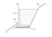
特許文献3には、山肌等の斜面102に道路を構築する場合の擁壁構築工法として、図13に示すような、縦版部111と底版部112とでL形をなすプレキャストコンクリートのL型擁壁ブロック(擁壁(躯体)101)を用いて斜面にL型土留め擁壁を構築する工法が記載されている。なお、図13自体は特許文献3における従来例であり、特許文献3の発明は、L型擁壁ブロック101の底版部112の根元側を厚く先端を薄くして下面を傾斜面にしたものである。
In
中詰め材充填カゴ枠1を積層設置する図12のカゴ枠擁壁4は、簡易な工法で施工性がよく、その点で林業専用道または森林作業道の築造に適していると言える。
しかし、作業に種々の困難を伴う森林での工事であるから、施工性をさらに向上させることが望まれる。
また、前記の通り、通常、道路の山側及び土留め擁壁の谷側には林地なので、林地の樹木伐採をできるだけ少なくするために、道路の幅員aに対して道路築造の土工領域bが極力狭く済むことが望まれる。
The cage
However, since it is a construction work in a forest with various difficulties in work, it is desired to further improve the workability.
In addition, as described above, since the forest is usually on the mountain side of the road and the valley side of the retaining wall, the earthwork area b for road construction is as much as possible with respect to the width a of the road in order to minimize the logging of the forest land. It is desirable to be narrow.
図13のようなL型擁壁ブロック101によるL型土留め擁壁は、引用文献3中の記載では、「道路側面や造成地側面や山肌等の斜面に擁壁を構築するため」の擁壁構築工法として、山肌等の斜面に適用する場合も想定しているが、平地の道路の土留め擁壁としては施工性の良好な工法であっても、林業専用道または森林作業道の場合、過重なL型擁壁ブロックを現場に運搬及び据付けするのが困難であり、また施工コストも高くなるし、適切ではない。
The L-type retaining wall by the L-type
本発明は上記事情に鑑みてなされたもので、林業専用道または森林作業道を作る際の土留め擁壁構築の施工性をさらに向上させ、施工コストを縮減させることができ、また、道路築造の道路幅方向の土工領域を極力狭く済ませて林地を極力多く残すことが可能な林業専用道または森林作業道の土留め擁壁及びその構築方法を提供することを目的とする。 The present invention has been made in view of the above circumstances, can further improve the workability of construction of retaining wall when making a forestry road or forest work road, can reduce the construction cost, road construction The purpose of the present invention is to provide an earth retaining wall for a forestry road or forest work road, and a method for constructing it, which can reduce the earthwork area in the road width direction as much as possible and leave as much forest as possible.
上記課題を解決する請求項1の発明は、林地である斜面に林業専用道または森林作業道を作る際に道路の谷側に、築造しようとする道路領域の谷側部分の一部を含む態様で斜面を掘削した上で、構築される林業専用道または森林作業道の土留め擁壁であって、
組み立てたカゴ枠に石礫または土砂などの中詰め材を充填して設置する、鉛直な前面部を持つ複数の中詰め材充填カゴ枠を谷側から道幅方向山側に順次ずらして積層設置し、最上段の中詰め材充填カゴ枠の上に、壁面高さがカゴ枠高さの約2倍の高さの鉛直な前面部を持つ1つのL形擁壁部を構成するための、現地組み立てが可能な複数の部材からなる鋼製のL形擁壁材を設置し、前記L形擁壁材の内側に土砂を充填し転圧して構築したことを特徴とする。
The invention of
The assembled cage frame is filled with medium packing materials such as stone gravel or earth and sand, and a plurality of medium filling material filling cage frames with a vertical front part are sequentially shifted from the valley side to the mountain side in the road width direction, and stacked. on the packed material filling basket frame in the top row, the wall height to constitute one L-shaped retaining wall portion having a vertical front section of about 2 times the height of the basket-frame height, local assembly A steel L-shaped retaining wall material composed of a plurality of members capable of being installed, and filled with earth and sand inside the L-shaped retaining wall material and rolled and constructed.
請求項2は、請求項1の林業専用道または森林作業道の土留め擁壁において、
前記L形擁壁材が、溶接金網をL形に屈曲してなるL形溶接金網と、前記L形溶接金網の左右両端部においてそれぞれL形溶接金網の底面部背面側端部と前面部天端部とを連結する補強用の斜め材と、前面部の高さ中間部において前面部に前端を連結された水平な鉄線を縦横約100mm間隔の格子状に溶接した補強メッシュとから構成されていることを特徴とする。
The L-shaped retaining wall material includes an L-shaped welded wire mesh formed by bending the welded wire mesh into an L-shape, and a bottom side rear side end and a front side ceiling of the L-shaped welded wire mesh at the left and right ends of the L-shaped welded wire mesh, respectively. It is composed of a reinforcing diagonal member that connects the end portions, and a reinforcing mesh that is formed by welding horizontal iron wires connected to the front end to the front portion at a height intermediate portion of the front portion in a lattice shape at intervals of about 100 mm vertically and horizontally. It is characterized by being.
請求項3は、請求項2の林業専用道または森林作業道の土留め擁壁において、L形擁壁材におけるL形溶接金網の左右両端部にそれぞれ、溶接金網の線材より大径の線材をL形溶接金網のL形に添うように折曲したL形鉄線枠を取り付け、前記斜め材の両端を前記L形鉄線枠の底面部背面側端部と前面部天端部とに連結したことを特徴とする。
請求項4は、請求項2又は3の林業専用道または森林作業道の土留め擁壁において、L形溶接金網の前面部の高さ中間部間に中間梁材を取り付け、この中間梁材に前記補強メッシュの前端部を取り付けたことを特徴とする。 According to a fourth aspect of the present invention, in the retaining wall of the forestry road or the forest working road according to the second or third aspect, an intermediate beam member is attached between the height intermediate portions of the front portion of the L-shaped welded wire mesh, and the intermediate beam member is attached to the intermediate beam member. A front end portion of the reinforcing mesh is attached.
請求項5の発明は、林地である斜面に林業専用道または森林作業道を作る際に道路の谷側に、築造しようとする道路領域の谷側部分の一部を含む態様で斜面を掘削した上で、土留め擁壁を構築する林業専用道または森林作業道の土留め擁壁構築方法であって、
組み立てたカゴ枠に石礫または土砂などの中詰め材を充填して設置する、鉛直な前面部を持つ複数の中詰め材充填カゴ枠を谷側から道幅方向山側に順次ずらして積層設置し、最上段の中詰め材充填カゴ枠の上に、壁面高さがカゴ枠高さの約2倍の高さの鉛直な前面部を持つ1つのL形擁壁部を構成するための、現地組み立てが可能な複数の部材からなる鋼製のL形擁壁材を設置し、前記L形擁壁材の内側に土砂を充填し転圧して構築することを特徴とする。
The invention according to claim 5 excavates the slope in a manner including a part of the valley side portion of the road area to be built on the valley side of the road when the forestry road or the forest working road is made on the slope that is the forest land . Above, a method for constructing a retaining wall for a forestry road or forest work road for constructing a retaining wall,
The assembled cage frame is filled with medium packing materials such as stone gravel or earth and sand, and a plurality of medium filling material filling cage frames with a vertical front part are sequentially shifted from the valley side to the mountain side in the road width direction, and stacked. on the packed material filling basket frame in the top row, the wall height to constitute one L-shaped retaining wall portion having a vertical front section of about 2 times the height of the basket-frame height, local assembly It is characterized in that a steel L-shaped retaining wall material made of a plurality of members that can be installed is installed, earth and sand are filled inside the L-shaped retaining wall material, and the material is rolled and constructed.
本発明の土留め擁壁は、カゴ枠と鋼製のL形擁壁材とで構築するが、カゴ枠及び鋼製のL形擁壁材は現場で組み立てできるので、プレキャストコンクリートのL形擁壁ブロックなどと比べて、現場への部材搬入が極めて容易であり、林業専用道や森林作業道の築造が容易になり、かつ施工費も安くできる。
カゴ枠の中詰材充填を含む組み立てには、フトン籠のような特殊技能を必要とせず、施工が簡単である。また、鋼製L形擁壁材も、請求項2のようにL形溶接金網と斜め材と補強メッシュとで構成することができ、その組み立ては容易であり特殊技能を必要としないので、施工が簡単である。したがって、工期短縮を図ることができる。これにより、林業専用道または森林作業道を容易にかつ安価に作ることができるとともに、年間の林業専用道または森林作業道の開設延長を長くすることが可能となる。
Retaining retaining wall of the present invention is constructed in a cage frame and steel L Katachiyo wall material, since the car frame and steel L Katachiyo wall material can be assembled on site, the precast concrete L-shaped retaining Compared to wall blocks, it is very easy to carry members into the site, and it is easy to build forestry roads and forest work roads, and construction costs can be reduced.
The assembly including filling of the packing material in the cage frame does not require special skills like Futon Sakai and is easy to construct. Also, the steel L-shaped retaining wall material can be composed of an L-shaped welded wire mesh, an oblique material and a reinforcing mesh as in
カゴ枠擁壁部とL形擁壁部との組み合わせであり、L形擁壁部が最上段なので、L形擁壁部の底面部上の土砂を前壁部に接する範囲まで転圧することができる。したがって、L形擁壁部の前壁部を道路側に極力接近させることが可能であり、中詰め材充填カゴ枠だけを積層設置するカゴ枠擁壁と比べて、道路幅方向の土工領域bを狭く済ませることができる。したがって、道路の山側や谷側の林地を多く残すことができ、樹木保全の観点から、林業専用道または森林作業道の構築方法として優れている。
また、カゴ枠擁壁部とL形擁壁部との組み合わせであり、L形擁壁部の前壁部が土圧を有効に支えることができるので、中詰め材充填カゴ枠だけを積層設置するカゴ枠擁壁と比べて、擁壁高さを低くすることができ、掘削量も少なく施工が簡単になり、施工コストを縮減できる。
A combination of a cage frame retaining wall portion and the L-shaped retaining wall portion, since the L-shaped retaining wall portion is uppermost, that pressure rolling the sediment on the bottom portion of the L-shaped retaining wall portion to the extent that is in contact with the front wall portion it can. Thus, the front wall portion of the L-shaped retaining wall unit is can be as much as possible close to the road side, only the medium filling material filling basket frame in comparison with the basket frame retaining wall for stacking installation, road width direction earthwork region b Can be narrowed. Therefore, a lot of forest land on the mountain side and valley side of the road can be left, and from the viewpoint of tree conservation, it is excellent as a construction method for forestry roads or forest work roads.
Also, a combination of a cage frame retaining wall portion and the L-shaped retaining wall portion, since the front wall portion of the L-shaped retaining wall unit can be supported to enable the earth pressure, laminating only medium filling material filling basket frame installation Compared with the cage frame retaining wall, the retaining wall height can be lowered, the amount of excavation is small and the construction is simplified, and the construction cost can be reduced.
カゴ枠及びL形擁壁材は、それぞれ壁面が鉛直面なので、道路のカーブに合わせて曲線状に配列する施工も、特殊な部材を使用せず自在にかつ容易に行うことができる。いわゆるヘアピンカーブにも容易に対応できる。
また、カゴ枠及びL形擁壁材は、L形擁壁ブロックと比べて、変形に対する自在性が顕著であり、特殊な部材を使用せずに道路勾配に合わせた施工を自在にかつ容易に行うことができ、坂道となることの多い林業専用道または森林作業道の施工法として極めて優れている。
Since each of the cage frame and the L-shaped retaining wall material has a vertical wall surface, it is possible to freely and easily perform the construction in which the walls are arranged in a curved shape according to the road curve without using a special member. It can easily handle so-called hairpin curves.
Also, the car frame and L Katachiyo wallboard, compared with L-shaped retaining wall blocks, a remarkable flexibility to deformation, the construction tailored to the road gradient without using special members freely and easily It is extremely excellent as a construction method for forestry roads or forest work roads that can be performed and often become slopes.
カゴ枠の中詰材料は、石礫と土砂から選択できるので、透水性が必要な箇所には石礫を中詰し、壁面を緑化したい場合は土砂を中詰することができる。
なお、仮にL形擁壁材のみで土留め擁壁を構築した場合、L形土留め擁壁には一般に土砂を中詰めするので、水抜き対策を必要とするが、本発明ではカゴ枠と組み合わせる構造なので、前記の通り、透水性が必要な箇所にも設置できる。
一般的にはL形擁壁の鉛直な壁面の緑化は難しいが、本発明の場合L形擁壁材によるL形擁壁部の高さは概ね1m程度とするので、L形擁壁部のすぐ下のカゴ枠擁壁部の露出した上面及びL形擁壁部天端法面からの植生により、L形擁壁部の壁面の緑化も可能となる。したがって、本発明の土留め擁壁は、L形擁壁部があっても壁面全体の緑化が十分可能である。
The filling material of the cage frame can be selected from stone gravel and earth and sand, so it can be filled with stone gravel at places where water permeability is necessary, and earth and sand can be filled when it is desired to green the wall surface.
If the earth retaining wall is constructed with only the L-shaped retaining wall material, the L-shaped retaining wall is generally filled with earth and sand, so measures for draining are required. Since it is a combined structure, it can be installed in places where water permeability is required as described above.
Although generally greening difficult for vertical walls of the L-shaped retaining wall, the height of the L-shaped retaining wall unit according to the case L-shaped Yokabezai of the present invention is generally set to about 1 m, the L-shaped retaining wall portion the immediate vegetation from the exposed upper surface and L-shaped retaining wall portion crest slopes of the car frame retaining wall of the lower, it is possible greening of the wall of the L-shaped retaining wall portion. Thus, earth retaining retaining wall of the present invention, it is sufficiently possible greening of the entire wall surface even if L-shaped retaining wall portion.
以下、本発明を実施した林業専用道または森林作業道の土留め擁壁、及びその構築方法について、図面を参照して説明する。 Hereinafter, a retaining wall for a forestry road or a forest work road, and a method for constructing the same will be described with reference to the drawings.
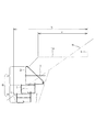
図1は本発明の一実施例の林業専用道または森林作業道の土留め擁壁を道路とともに模式的に示した断面図である。図2は図1の土留め擁壁の具体的な構造を示した断面図である。図3は図2の土留め擁壁の正面図、図4は図2の土留め擁壁の平面図である。
この土留め擁壁6を構築する場合、まず、地山における設定した道路位置の谷側部分を掘削して、固い地盤7を露出させる。掘削した部分を破線で示す。固い地盤7の上に最下段のカゴ枠1を配置し、カゴ枠1内に土砂や栗石を充填する。
次いで、最下段の中詰め材充填カゴ枠1の上に2段目のカゴ枠1を下段のカゴ枠1に対して道路幅方向山側にずらして配置し、前記と同様にカゴ枠1内に土砂や栗石を充填する。これにより、図示例では2段の中詰め材充填カゴ枠1からなるカゴ枠擁壁部4が得られる。カゴ枠1の前後の空間に先に掘削した土砂を埋め戻す。
次いで、上段の中詰め材充填カゴ枠1の上に鋼製のL形擁壁材2を配置し、L形擁壁材2の内側に土砂を充填する。この場合、土砂をL形擁壁材の高さの半分まで充填・転圧した段階で、補強メッシュ3を水平に配置し、その前端をL形擁壁材2の前壁の高さ中間位置に連結する。さらに土砂を充填し、次いで、土砂を転圧して、L型擁壁部5を形成する。
こうして、カゴ枠擁壁部4の上にL型擁壁部5を設けた土留め擁壁6が得られる。
なお、設定した道路位置の山側部分を切り取る作業は、土留め擁壁6の構築の作業工程に合わせて、適宜に行うとよい。
図1において、10は築造された道路面、mは現況地山線、nは道路の山側の模式的に示した切土壁面である。道路の山側及び土留め擁壁の谷側には通常、図示のように林地となっている。aは道路の幅員、bは道路築造の土工領域(施工範囲)を示す。
図3に示すように、実施例の土留め擁壁におけるカゴ枠擁壁部4の高さは0.5m、L型擁壁部5の高さは1.0mである。1つのL形擁壁材2の幅は1.0m、1つのカゴ枠1の幅は2.0mである。なお、図4の平面図では、L型擁壁材2における後述するL形溶接金網12の底面部12bと補強メッシュ3とが重なって見えるので、区別のためにその重なって見える部分を破線で示している。
FIG. 1 is a cross-sectional view schematically showing an earth retaining wall of a forestry road or forest work road according to an embodiment of the present invention together with a road. FIG. 2 is a cross-sectional view showing a specific structure of the retaining wall of FIG. 3 is a front view of the retaining wall of FIG. 2, and FIG. 4 is a plan view of the retaining wall of FIG.
When constructing this
Next, the second-
Next, an L-shaped
Thus, the
In addition, it is good to perform the operation | work which cuts off the mountain side part of the set road position suitably according to the operation | work process of construction of the
In FIG. 1, 10 is a built road surface, m is an existing ground mountain line, and n is a cut wall surface schematically shown on the mountain side of the road. The mountain side of the road and the valley side of the retaining wall are usually forested as shown. a indicates the width of the road, and b indicates the earthwork area (construction range) for road construction.
As shown in FIG. 3, the height of the cage frame retaining
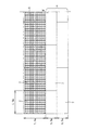
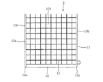
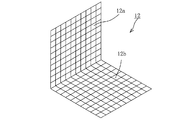
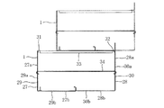
前記L形擁壁材2の詳細を図5〜図8に示す。このL形擁壁材2は、溶接金網をL形に屈曲してな図8に示すL形溶接金網12と、図5〜図7に示すようにL形溶接金網12の左右両端部にそれぞれ取り付けられる、溶接金網の線材より大径の線材をL形溶接金網12のL形に添うように折曲したL形鉄線枠13と、前記L形鉄線枠13の底面部13bの背面側端部と前面部13aの天端とを連結する補強用の斜め材14と、L形溶接金網12の前面部12aの高さ中間部において前面部に前端を連結された水平な補強メッシュ3とを備えている。
前記L形溶接金網12の溶接金網は径6mmの鉄線を縦横100mm間隔の格子状に溶接したものである。L形溶接金網12の上端縁に山形鋼の上部梁材16を溶接固定し、前記斜め材14の上端部は天端プレート17を介して上部梁材16に固定されている。斜め材14の下端部とL形鉄線枠13の底面部13bの背面側端部とはそれぞれの端部に形成したフック部14a、13cを互いに係合させている。
前記L形鉄線枠13の鉄線径は16mmである。18は植生シートである。
前記補強メッシュ3は、溶接金網を同じく、径6mmの鉄線を縦横100mm間隔の格子状に溶接したものである。
前記L形溶接金網12の前面の高さ中間部に中間梁材19が一体に溶接固定されている。そして、あまり長くないコイルスプリング20が、中間梁材19とL形溶接金網12の前面部12aの縦線12a1と横線12a2と補強メッシュ3の鉄線3aとに絡まるように取り付けられており、このコイルスプリング20で補強メッシュ3の前端部が中間梁材19とL形溶接金網12に取り付けられている。
Details of the L-shaped
The welded wire mesh of the L-shaped welded
The iron wire diameter of the L-shaped
The reinforcing
An
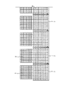
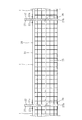
前記カゴ枠1の詳細を図9〜図11に示す。このカゴ枠1は、溶接金網をL形に折曲した図11のような2つのL形金網25、26(一方のL形金網26は2点鎖線で輪郭のみを図示)の一方のL形金網25の左右両端にL形の前面枠27を取り付けてなるL形のカゴ枠半体29と、他方のL形金網26の左右両端にL形の後面枠28を取り付けてなるL形のカゴ枠半体30とを、図9のように対向させ、カゴ枠1の正面から見た左右両端においてそれぞれ、前面枠27の底部27bの先端と後面枠28の底部28bの先端とを互いに係合させてコ字形に組み立て、さらに前面枠27の上端に固定した上部桁材31と後面枠28の上端に固定した上部桁材32との間を上部梁材33で連結し、前面枠27の前面部27aの高さ中間部と後面枠28の後面部28aの高さ中間部とを中間梁材34で連結している。中間梁材34の前後端部はいずれもフック状に折曲しており、前端部は、隣接するカゴ枠1の2つの前面枠27の前面部27aの両者に引っ掛け、後端部は、隣接するカゴ枠1の2つの後面枠28の2つの後面部28aの両者に引っ掛けて、連結している。
Details of the
上記の通り本発明の土留め擁壁は、カゴ枠1と鋼製のL形擁壁材2とで構築するが、カゴ枠1及び鋼製のL形擁壁材2は現場で組み立てできるので、プレキャストのL型擁壁ブロックなどと比べて、単位当たり重量が大きく違うことで現場への部材搬入や据付が極めて容易であり、林業専用道や森林作業道の築造が容易になり、かつ施工費も安くできる。
カゴ枠1の中詰材充填を含む組み立てには、フトン籠のような特殊技能を必要とせず、施工が簡単である。また、鋼製L形擁壁材2も、上述の通りL形溶接金網12とL形鉄線枠13と斜め材14と補強メッシュ3とで構成することができ、その組み立ては容易であり特殊技能を必要としないので、施工が簡単である。したがって、工期短縮を図ることができる。これにより、林業専用道または森林作業道を容易にかつ安価に作ることができるとともに、年間の林業専用道または森林作業道の開設延長を長くすることが可能となる。
また、カゴ枠擁壁部4とL型擁壁部5との組み合わせであり、L型擁壁部5が最上段なので、L型擁壁部5の底面部上の土砂を前壁部に接する範囲まで転圧することができる。したがって、L型擁壁部の前壁部を道路側に極力接近させることが可能であり、中詰め材充填カゴ枠だけを積層設置するカゴ枠擁壁と比べて、道路幅方向の土工領域bを狭く済ませることができる。したがって、道路の山側や谷側の林地を多く残すことができ、樹木保全の観点から、林業専用道または森林作業道の構築方法として優れている。例えば、図12に示した中詰め材充填カゴ枠のみを積層設置する従来のカゴ枠擁壁の場合、幅員aが4.0mの道路を作る場合、土工領域bが6.6m程度となるが、本発明の工法によれば、土工領域bが5.7m程度で済む(図1、図2参照)。
また、カゴ枠擁壁部4とL型擁壁部5との組み合わせであり、L型擁壁部5の前壁部が土圧を有効に支えることができるので、中詰め材充填カゴ枠だけを積層設置するカゴ枠擁壁と比べて、擁壁高さを低くすることができ、掘削量も少なく施工が簡単になり、施工コストを縮減できる。
また、カゴ枠1及びL形擁壁材2は、それぞれ壁面が鉛直面なので、道路のカーブに合わせて曲線状に配列する施工も、特殊な部材を使用せず自在にかつ容易に行うことができる。いわゆるヘアピンカーブにも容易に対応できる。
また、カゴ枠1及びL形擁壁材2は、L型擁壁ブロックと比べて、変形に対する自在性が顕著であり、特殊な部材を使用せずに道路勾配に合わせた施工を自在にかつ容易に行うことができ、坂道となることの多い林業専用道または森林作業道の施工法として極めて優れている。
As described above, the earth retaining wall of the present invention is constructed by the
The assembly including filling the filling material of the
Moreover, it is a combination of the cage frame retaining
In addition, it is a combination of the cage frame retaining
In addition, since the
In addition, the
カゴ枠の中詰材料は、石礫と土砂から選択できるので、透水性が必要な箇所には石礫を中詰し、壁面を緑化したい場合は土砂を中詰することができる。
なお、仮にL形擁壁材のみで土留め擁壁を構築した場合、L型土留め擁壁には一般に土砂を中詰めするので、透水性が必要な箇所には適さないが、本発明ではカゴ枠と組み合わせる構造なので、前記の通り、透水性が必要な箇所にも設置できる。
一般的にはL型擁壁の壁面の緑化は難しい。すなわち、L型土留め擁壁は壁面が鉛直なので、その鉛直壁面に種が付着しても落下する恐れが高く、このため、L形土留め擁壁の壁面に良好な緑化を施すことは難しい。しかし、L型土留め擁壁でも高さが1m程度であれば、L型土留め擁壁の基礎平坦部および天端部法面からの植生により、緑化が可能となる。本発明の場合、L型擁壁材2によるL型擁壁部5の高さは概ね1m程度とするので、L型擁壁部5のすぐ下のカゴ枠擁壁部4の露出した上面(L型土留め擁壁の基礎平坦部に相当)、及びL型擁壁部天端法面からの植生により、L型擁壁部5の壁面の緑化も可能となる。したがって、本発明の土留め擁壁は、L型擁壁部があっても壁面全体の緑化が十分可能である。
The filling material of the cage frame can be selected from stone gravel and earth and sand, so it can be filled with stone gravel at places where water permeability is necessary, and earth and sand can be filled when it is desired to green the wall surface.
In addition, when the earth retaining wall is constructed only with the L-shaped retaining wall material, the L-shaped earth retaining wall is generally filled with earth and sand, so it is not suitable for a place where water permeability is necessary. Since it is a structure combined with a cage frame, it can be installed in places where water permeability is necessary as described above.
In general, greening of the wall surface of the L-shaped retaining wall is difficult. That is, since the wall surface of the L-type retaining wall is vertical, there is a high risk of falling even if seeds adhere to the vertical wall surface. Therefore, it is difficult to give good greening to the wall surface of the L-shaped retaining wall. . However, if the height of the L-type retaining wall is about 1 m, it can be planted by vegetation from the foundation flat portion and the top end slope of the L-shaped retaining wall. In the case of the present invention, the height of the L-shaped
上記実施例の土留め擁壁6は、中詰め材充填カゴ枠1が2段であるが、3段以上とすることも考えられる。また、中詰め材充填カゴ枠1が1段の場合も考えられる。
カゴ枠1内に充填する中詰材は土砂、石礫のいずれでもよいが、複数段の中詰め材充填カゴ枠の一部の中詰め材を石礫、他を土砂とする場合もある。
L形擁壁材の高さはカゴ枠高さの約2倍であるが、厳格に2倍である必要はない。
上述の実施例では、道路の舗装については言及しなかったが、必要に応じて舗装することができる。なお、林業専用道は一般には砂利道であるが、勾配が7%を超える場合は舗装する。また、森林作業道は一般に舗装はしない。
In the
The filling material to be filled in the
The height of the L-shaped retaining wall material is about twice the height of the cage frame, but need not be strictly twice.
In the above-described embodiment, the road pavement is not mentioned, but can be paved as necessary. Forestry roads are generally gravel roads, but paved when the slope exceeds 7%. In general, forest roads are not paved.
1 カゴ枠(中詰め材充填カゴ枠)
2 L形擁壁材
3 補強メッシュ
3a (補強メッシュの)鉄線
4 カゴ枠擁壁部
5 L型擁壁部
6 土留め擁壁
7 固い地盤
m 現況地山線
n 切土壁面
a 道路の幅員
b 道路築造の土工領域(施工範囲)
12 L形溶接金網
13 L形鉄線枠
12a、13a 前面部
12b、13b 底面部
14 斜め材
16 上部梁材
17 天端プレート
14a、13c フック部
18 植生シート
19 中間梁材
20 コイルスプリング
25、26 L形金網
27 前面枠
27a 前面部
27b 底部
28 後面枠
28a 後面部
28b 底部
29 (前面側の)カゴ枠半体
30 (後面側の)カゴ枠半体
31、32 上部桁材
33 上部梁材
34 中間梁材
1 Basket frame (filled basket frame filled with filling material)
2 L-shaped
12 L-shaped welded wire mesh 13 L-shaped
Claims (5)
組み立てたカゴ枠に石礫または土砂などの中詰め材を充填して設置する、鉛直な前面部を持つ複数の中詰め材充填カゴ枠を谷側から道幅方向山側に順次ずらして積層設置し、最上段の中詰め材充填カゴ枠の上に、壁面高さがカゴ枠高さの約2倍の高さの鉛直な前面部を持つ1つのL形擁壁部を構成するための、現地組み立てが可能な複数の部材からなる鋼製のL形擁壁材を設置し、前記L形擁壁材の内側に土砂を充填し転圧して構築したことを特徴とする林業専用道または森林作業道の土留め擁壁。 Forestry constructed after excavating the slope in a manner that includes a part of the valley side portion of the road area to be built on the valley side of the road when creating a forestry road or forest work road on the slope that is the forest land A retaining wall for a private road or forest work road,
The assembled cage frame is filled with medium packing materials such as stone gravel or earth and sand, and a plurality of medium filling material filling cage frames with a vertical front part are sequentially shifted from the valley side to the mountain side in the road width direction, and stacked. on the packed material filling basket frame in the top row, the wall height to constitute one L-shaped retaining wall portion having a vertical front section of about 2 times the height of the basket-frame height, local assembly A forestry road or forest work road characterized in that it is constructed by installing steel L-shaped retaining wall materials composed of a plurality of members that can be used , filling the inside of the L-shaped retaining wall materials with earth and sand and rolling them Earth retaining wall.
組み立てたカゴ枠に石礫または土砂などの中詰め材を充填して設置する、鉛直な前面部を持つ複数の中詰め材充填カゴ枠を谷側から道幅方向山側に順次ずらして積層設置し、最上段の中詰め材充填カゴ枠の上に、壁面高さがカゴ枠高さの約2倍の高さの鉛直な前面部を持つ1つのL形擁壁部を構成するための、現地組み立てが可能な複数の部材からなる鋼製のL形擁壁材を設置し、前記L形擁壁材の内側に土砂を充填し転圧して構築することを特徴とする林業専用道または森林作業道の土留め擁壁構築方法。 When excavating the slope in a way that includes a part of the valley side portion of the road area to be built on the valley side of the road when creating a forestry road or forest work road on the slope that is the forest land, retaining the retaining wall A method for constructing a retaining wall for a forestry road or forest work road,
The assembled cage frame is filled with medium packing materials such as stone gravel or earth and sand, and a plurality of medium filling material filling cage frames with a vertical front part are sequentially shifted from the valley side to the mountain side in the road width direction, and stacked. on the packed material filling basket frame in the top row, the wall height to constitute one L-shaped retaining wall portion having a vertical front section of about 2 times the height of the basket-frame height, local assembly A forestry road or forest work road characterized in that an L-shaped retaining wall member made of steel consisting of a plurality of members that can be installed is constructed by filling and rolling earth and sand inside the L-shaped retaining wall material How to build earth retaining walls.
Priority Applications (1)
| Application Number | Priority Date | Filing Date | Title |
|---|---|---|---|
| JP2010281852A JP5691069B2 (en) | 2010-12-17 | 2010-12-17 | Earth retaining wall of forestry road or forest work road and its construction method |
Applications Claiming Priority (1)
| Application Number | Priority Date | Filing Date | Title |
|---|---|---|---|
| JP2010281852A JP5691069B2 (en) | 2010-12-17 | 2010-12-17 | Earth retaining wall of forestry road or forest work road and its construction method |
Publications (2)
| Publication Number | Publication Date |
|---|---|
| JP2012127160A JP2012127160A (en) | 2012-07-05 |
| JP5691069B2 true JP5691069B2 (en) | 2015-04-01 |
Family
ID=46644487
Family Applications (1)
| Application Number | Title | Priority Date | Filing Date |
|---|---|---|---|
| JP2010281852A Active JP5691069B2 (en) | 2010-12-17 | 2010-12-17 | Earth retaining wall of forestry road or forest work road and its construction method |
Country Status (1)
| Country | Link |
|---|---|
| JP (1) | JP5691069B2 (en) |
Families Citing this family (5)
| Publication number | Priority date | Publication date | Assignee | Title |
|---|---|---|---|---|
| JP5868352B2 (en) * | 2013-06-10 | 2016-02-24 | 旭化成ジオテック株式会社 | How to lay a road on the slope |
| US9534901B2 (en) | 2014-12-11 | 2017-01-03 | International Business Machines Corporation | Access route optimization for harvestable resources |
| CN108914730A (en) * | 2018-08-20 | 2018-11-30 | 中交路桥北方工程有限公司 | A kind of side slope protection road |
| JP7158016B2 (en) * | 2018-10-31 | 2022-10-21 | 共和ハーモテック株式会社 | Cage structure for retaining earth and method for forming the same |
| JP7182507B2 (en) * | 2019-04-02 | 2022-12-02 | 公益財団法人鉄道総合技術研究所 | Car frame structure and embankment restoration method using the same |
Family Cites Families (4)
| Publication number | Priority date | Publication date | Assignee | Title |
|---|---|---|---|---|
| JP2000328577A (en) * | 1999-05-24 | 2000-11-28 | Sumitomo Metal Steel Products Inc | Soil retaining cage frame and method of building steep grade banking using the cage frame |
| JP3714885B2 (en) * | 2001-04-12 | 2005-11-09 | 天龍工業株式会社 | Protection structures for slopes, walls, shores, etc. |
| JP3564423B2 (en) * | 2001-05-15 | 2004-09-08 | 住友金属建材株式会社 | Reinforced embankment structure |
| JP2005273377A (en) * | 2004-02-23 | 2005-10-06 | Kyowa Harmotech Kk | Mixed retaining wall, and method for constructing the same |
-
2010
- 2010-12-17 JP JP2010281852A patent/JP5691069B2/en active Active
Also Published As
| Publication number | Publication date |
|---|---|
| JP2012127160A (en) | 2012-07-05 |
Similar Documents
| Publication | Publication Date | Title |
|---|---|---|
| JP5691069B2 (en) | Earth retaining wall of forestry road or forest work road and its construction method | |
| JP7078501B2 (en) | Drainage channel structure of small slopes and its construction method | |
| JP5939970B2 (en) | Seismic reinforcement construction method and seismic reinforcement structure | |
| KR101206668B1 (en) | Multilayer revetment structure using natural strones | |
| JP5309378B2 (en) | Self-supporting retaining wall | |
| JP6948663B2 (en) | Retaining wall and its formation method | |
| KR101633853B1 (en) | An eco-friendly gabibolck for retaining wall with modular retaining wall | |
| CN109826230A (en) | A kind of town road pipeline reinforcement protection structure and its construction method | |
| KR102542559B1 (en) | Structure and Method for Supporting Retaining Wall using Raker | |
| JPH0988080A (en) | Sheathing structure | |
| JPS6140914A (en) | Erosion control dam and its construction | |
| JP6718840B2 (en) | Slope protection structure and method of forming the same | |
| JP2011219919A (en) | Retaining wall unit and method of constructing retaining wall unit | |
| JP4629559B2 (en) | Drain structure and construction method of drain structure | |
| JP6017302B2 (en) | Construction and its construction method | |
| JP6721185B2 (en) | Futon basket body panel, futon basket, and civil engineering structure | |
| JP2010116715A (en) | Retaining wall construction method | |
| JP7356735B2 (en) | Cage frame unit, cage frame connection body, cage frame laminate, and retaining wall construction method | |
| JP2006037507A (en) | Stone-filled gabion and partition panel | |
| JP3104772U (en) | Earth retaining wall | |
| KR102692110B1 (en) | Construction method of mattress-type gabion equipped with fixing unit to prevent curling | |
| JP4147090B2 (en) | Underground water tank structure and its construction method | |
| CN111254938B (en) | Foundation pit supporting structure based on side wall of underground chamber and reverse construction method thereof | |
| JP7008662B2 (en) | Retaining wall | |
| JP2011069156A (en) | Slope protective structure and connection bracket used for protection of slope |
Legal Events
| Date | Code | Title | Description |
|---|---|---|---|
| A621 | Written request for application examination |
Free format text: JAPANESE INTERMEDIATE CODE: A621 Effective date: 20131113 |
|
| A977 | Report on retrieval |
Free format text: JAPANESE INTERMEDIATE CODE: A971007 Effective date: 20140619 |
|
| A131 | Notification of reasons for refusal |
Free format text: JAPANESE INTERMEDIATE CODE: A131 Effective date: 20140701 |
|
| A521 | Request for written amendment filed |
Free format text: JAPANESE INTERMEDIATE CODE: A523 Effective date: 20140901 |
|
| TRDD | Decision of grant or rejection written | ||
| A01 | Written decision to grant a patent or to grant a registration (utility model) |
Free format text: JAPANESE INTERMEDIATE CODE: A01 Effective date: 20150113 |
|
| A61 | First payment of annual fees (during grant procedure) |
Free format text: JAPANESE INTERMEDIATE CODE: A61 Effective date: 20150113 |
|
| R150 | Certificate of patent or registration of utility model |
Ref document number: 5691069 Country of ref document: JP Free format text: JAPANESE INTERMEDIATE CODE: R150 |
|
| R250 | Receipt of annual fees |
Free format text: JAPANESE INTERMEDIATE CODE: R250 |
|
| R250 | Receipt of annual fees |
Free format text: JAPANESE INTERMEDIATE CODE: R250 |
|
| R250 | Receipt of annual fees |
Free format text: JAPANESE INTERMEDIATE CODE: R250 |
|
| R250 | Receipt of annual fees |
Free format text: JAPANESE INTERMEDIATE CODE: R250 |
|
| R250 | Receipt of annual fees |
Free format text: JAPANESE INTERMEDIATE CODE: R250 |
|
| R250 | Receipt of annual fees |
Free format text: JAPANESE INTERMEDIATE CODE: R250 |
|
| R250 | Receipt of annual fees |
Free format text: JAPANESE INTERMEDIATE CODE: R250 |