JP5686952B2 - Film forming apparatus and method including temperature and emissivity / pattern compensation - Google Patents
Film forming apparatus and method including temperature and emissivity / pattern compensation Download PDFInfo
- Publication number
- JP5686952B2 JP5686952B2 JP2008533387A JP2008533387A JP5686952B2 JP 5686952 B2 JP5686952 B2 JP 5686952B2 JP 2008533387 A JP2008533387 A JP 2008533387A JP 2008533387 A JP2008533387 A JP 2008533387A JP 5686952 B2 JP5686952 B2 JP 5686952B2
- Authority
- JP
- Japan
- Prior art keywords
- substrate
- emissivity
- processing system
- temperature
- heating
- Prior art date
- Legal status (The legal status is an assumption and is not a legal conclusion. Google has not performed a legal analysis and makes no representation as to the accuracy of the status listed.)
- Expired - Fee Related
Links
Images


Classifications
-
- C—CHEMISTRY; METALLURGY
- C23—COATING METALLIC MATERIAL; COATING MATERIAL WITH METALLIC MATERIAL; CHEMICAL SURFACE TREATMENT; DIFFUSION TREATMENT OF METALLIC MATERIAL; COATING BY VACUUM EVAPORATION, BY SPUTTERING, BY ION IMPLANTATION OR BY CHEMICAL VAPOUR DEPOSITION, IN GENERAL; INHIBITING CORROSION OF METALLIC MATERIAL OR INCRUSTATION IN GENERAL
- C23C—COATING METALLIC MATERIAL; COATING MATERIAL WITH METALLIC MATERIAL; SURFACE TREATMENT OF METALLIC MATERIAL BY DIFFUSION INTO THE SURFACE, BY CHEMICAL CONVERSION OR SUBSTITUTION; COATING BY VACUUM EVAPORATION, BY SPUTTERING, BY ION IMPLANTATION OR BY CHEMICAL VAPOUR DEPOSITION, IN GENERAL
- C23C16/00—Chemical coating by decomposition of gaseous compounds, without leaving reaction products of surface material in the coating, i.e. chemical vapour deposition [CVD] processes
- C23C16/44—Chemical coating by decomposition of gaseous compounds, without leaving reaction products of surface material in the coating, i.e. chemical vapour deposition [CVD] processes characterised by the method of coating
- C23C16/48—Chemical coating by decomposition of gaseous compounds, without leaving reaction products of surface material in the coating, i.e. chemical vapour deposition [CVD] processes characterised by the method of coating by irradiation, e.g. photolysis, radiolysis, particle radiation
- C23C16/481—Chemical coating by decomposition of gaseous compounds, without leaving reaction products of surface material in the coating, i.e. chemical vapour deposition [CVD] processes characterised by the method of coating by irradiation, e.g. photolysis, radiolysis, particle radiation by radiant heating of the substrate
-
- C—CHEMISTRY; METALLURGY
- C23—COATING METALLIC MATERIAL; COATING MATERIAL WITH METALLIC MATERIAL; CHEMICAL SURFACE TREATMENT; DIFFUSION TREATMENT OF METALLIC MATERIAL; COATING BY VACUUM EVAPORATION, BY SPUTTERING, BY ION IMPLANTATION OR BY CHEMICAL VAPOUR DEPOSITION, IN GENERAL; INHIBITING CORROSION OF METALLIC MATERIAL OR INCRUSTATION IN GENERAL
- C23C—COATING METALLIC MATERIAL; COATING MATERIAL WITH METALLIC MATERIAL; SURFACE TREATMENT OF METALLIC MATERIAL BY DIFFUSION INTO THE SURFACE, BY CHEMICAL CONVERSION OR SUBSTITUTION; COATING BY VACUUM EVAPORATION, BY SPUTTERING, BY ION IMPLANTATION OR BY CHEMICAL VAPOUR DEPOSITION, IN GENERAL
- C23C16/00—Chemical coating by decomposition of gaseous compounds, without leaving reaction products of surface material in the coating, i.e. chemical vapour deposition [CVD] processes
- C23C16/44—Chemical coating by decomposition of gaseous compounds, without leaving reaction products of surface material in the coating, i.e. chemical vapour deposition [CVD] processes characterised by the method of coating
- C23C16/52—Controlling or regulating the coating process
Description
[0001]本発明の実施形態は概して反応チャンバと膜形成装置および方法に関する。 [0001] Embodiments of the present invention generally relate to reaction chambers and film forming apparatus and methods.
[0002]過去数年にわたって、単結晶シリコン膜の低温堆積を必要とする用途数がかなり増大した。この用途の例としては、ブランケットシリコンゲルマニウム膜、エレベートおよび/またはリセスソースドレイン選択堆積、引張または圧縮制約による膜などを含むがこれらに制限されない。具体的な用途に応じて、これらのプロセスは全て、膜を成長させるのに使用される圧力、温度および化学物質において大きく異なることがある。しかしながら、これらのプロセスが共通して有する要件の1つは、ウェーハの温度の極めて慎重、正確かつ均一なコントロールを必要とするということである。 [0002] Over the past few years, the number of applications requiring low temperature deposition of single crystal silicon films has increased considerably. Examples of this application include, but are not limited to, blanket silicon germanium films, elevated and / or recessed source / drain selective deposition, films with tensile or compression constraints, and the like. Depending on the specific application, all of these processes can vary greatly in the pressure, temperature and chemicals used to grow the film. However, one of the requirements these processes have in common is that they require very careful, accurate and uniform control of the wafer temperature.
[0003](200mmおよび300mmの両用途向けの)シングルウェーハシリコン堆積CVDチャンバはこれまで長年にわたって使用可能であった。しかしながら、この機器は、高温(約1100℃)のブランケット大気エピタキシャル条件を主に念頭において設計されたものであった。このような高温用途から、より新しい低温用途に推移する時にはこのような機器の性能に影響を与える複数の要因がある。 [0003] Single wafer silicon deposition CVD chambers (for both 200 mm and 300 mm applications) have been available for many years. However, this instrument was designed primarily with high temperature (about 1100 ° C.) blanket atmospheric epitaxial conditions in mind. There are several factors that affect the performance of such equipment when transitioning from such high temperature applications to newer low temperature applications.
[0004]まず、通常シリコン前駆体ガスとしてトリクロロシランを使用する高温大気エピタキシャル用途は質量移送制限プロセスである。これは、反応剤が表面に送出されるレートと比較して極めて迅速に化学堆積反応が生じることを意味しており、シリコン膜の均一性を判断する際の主要要因はガス流の均一性である。このような用途の温度コントロールは二次要因である。例証として、通常の3ミクロンの1130℃大気エピタキシャルプロセスについて、(大域的またはウェーハ全体の)温度エラーの各摂氏温度は、0.004ミクロン、つまりわずか0.13%の膜厚偏差を発生させる。1σ当たり約0.8%の通常の工業均一性要件において、これは、チャンバはウェーハ全体の温度均一性の1σ当たり約6℃を維持する必要があることを意味している。この仕様を満たすのは比較的容易である。当分野で知られているように、σはデータの標準偏差を示すのに使用される統計用語である。膜厚は通常多数のポイントで測定され、σは、確率関数、つまり確率密度関数がこの平均付近に集中される様子を示している。 [0004] First, high temperature atmospheric epitaxial applications that typically use trichlorosilane as the silicon precursor gas are mass transport limited processes. This means that the chemical deposition reaction occurs very quickly compared to the rate at which the reactants are delivered to the surface, and the main factor in determining the uniformity of the silicon film is the gas flow uniformity. is there. Temperature control for such applications is a secondary factor. By way of illustration, for a normal 3 micron 1130 ° C. atmospheric epitaxial process, each Celsius of temperature error (global or wafer wide) produces a film thickness deviation of 0.004 microns, or only 0.13%. At a typical industrial uniformity requirement of about 0.8% per sigma, this means that the chamber needs to maintain about 6 ° C. per sigma of temperature uniformity across the wafer. It is relatively easy to meet this specification. As is known in the art, σ is a statistical term used to indicate the standard deviation of data. The film thickness is usually measured at a number of points, and σ indicates the probability function, that is, the probability density function is concentrated near this average.
[0005]反対に、低温エピタキシャル用途は反応レート制限プロセスのカテゴリーに該当する。(例えば、約600〜900℃の)通常のプロセス温度では、基板表面での反応は、表面へのガス移送レートと比較して遅く、大域的な温度および基板全体の温度均一性は、膜特性をコントロールする最も重要なプロセスパラメータである。例証として、通常の選択エピタキシャル膜は約300Å厚であってもよく、1σ当たり約0.1%の均一性を必要としており、この値は、各新たなデバイス生成によって小さくなる。この体制において、温度変動の各摂氏温度は約3Åの膜厚変動を発生させる。1σ当たり1%の均一性は温度コントロールに関して1σ当たり約1℃に変換する。従って、エピタキシャル堆積機器の現在の生成に関する改良における係数6がこのようなプロセスコントロールには必要とされる。 [0005] Conversely, low temperature epitaxial applications fall into the category of reaction rate limiting processes. At normal process temperatures (eg, about 600-900 ° C.), the reaction at the substrate surface is slow compared to the gas transfer rate to the surface, and the global temperature and temperature uniformity across the substrate is dependent on film properties. Is the most important process parameter to control. By way of illustration, a typical selective epitaxial film may be about 300 mm thick, requiring about 0.1% uniformity per σ, and this value becomes smaller with each new device creation. In this system, each Celsius temperature of temperature variation causes a film thickness variation of about 3 mm. A uniformity of 1% per sigma translates to about 1 ° C per sigma for temperature control. Therefore, a factor of 6 in improving on the current production of epitaxial deposition equipment is required for such process control.
[0006]これらの新たなプロセスの機器性能に影響を与える第2の要因は、ウェーハ放射率を担い、かつ補正するという必要性であり、これは温度測定の精度、ならびにこれらの反応器の選択技術である放射ランプによってウェーハが加熱されるレートおよび方法の両方に影響する。エピタキシャルチャンバの現在の生成は主にブランケットシリコンウェーハを処理するように設計されており、これは基板表面全体に一定かつ均一な放射率特徴を有している。このため、放射率効果は簡単に機器に較正可能である。先端の選択低温プロセスはデバイスウェーハ(その上に部分的に集積回路がプリントされているウェーハ)を目的としており、これは、放射率が既知の係数であることも、このプロパティがウェーハ全体で一定であることも意味していない。 [0006] A second factor affecting the equipment performance of these new processes is the need to account for and correct for wafer emissivity, which is the accuracy of temperature measurements, as well as the choice of these reactors. It affects both the rate and the way in which the wafer is heated by the technology radiant lamp. Current generation of epitaxial chambers is designed primarily to process blanket silicon wafers, which have constant and uniform emissivity characteristics across the substrate surface. For this reason, the emissivity effect can be easily calibrated to the instrument. The advanced selective cryogenic process is aimed at device wafers (wafers with partially integrated circuits printed on them), which also have a known coefficient of emissivity, and this property is constant across the wafer It does not mean that.
[0007]必要とされている厳密な温度コントロールを依然として維持しつつこの変動を補償可能なエピタキシャル機器を提供することが望ましい。従って、より厳密な温度監視およびコントロール、ならびに放射率およびパターン補償を提供する新たな膜形成システムが非常に望ましい。 [0007] It would be desirable to provide an epitaxial device that can compensate for this variation while still maintaining the exact temperature control required. Accordingly, new film forming systems that provide more stringent temperature monitoring and control, and emissivity and pattern compensation are highly desirable.
[0008]本発明の態様は、基板の温度の精密な監視およびコントロールを提供する膜形成システムおよび方法に関する。本発明の一態様は処理チャンバを含む。一実施形態では、該処理チャンバは側壁によって境界を画定されており、第1の周辺部材は、該処理チャンバに延びる内周縁を有しており、該側壁の少なくとも一部付近に配置されている。サセプタなどの基板サポートは該システム内に配置される。 [0008] Aspects of the invention relate to film formation systems and methods that provide precise monitoring and control of substrate temperature. One aspect of the invention includes a processing chamber. In one embodiment, the processing chamber is bounded by a sidewall, and the first peripheral member has an inner periphery that extends to the processing chamber and is disposed near at least a portion of the sidewall. . A substrate support, such as a susceptor, is placed in the system.
[0009]本発明の一実施形態では、上部カバーが該処理チャンバをカバーするために提供される。本実施形態によると、該上部カバーは該基板サポートの上方に配置されており、また該基板サポートに光を反射し返す反射表面を備えている。一実施形態では、該反射表面は、該基板の有効放射率を増大させるために、該基板から発せられる光を該基板に反射し返すように設計されている。別の実施形態では、複数の光プローブが、該基板から発せられる光を収集して種々の場所で温度を測定するために提供されてもよい。該反射表面は複数の開口を有してもよく、これらの各々はそれぞれの光プローブに視界を提供する。一実施形態では、該光プローブの該視界は該基板を越えては延びない。別の実施形態では、該光プローブの全てが該基板の半径方向に沿って実質的に等距離に間隔をあけられている。該光プローブは光高温計と、信号を信号処理機器へ搬送するための光ファイバとを備えてもよい。 [0009] In one embodiment of the invention, a top cover is provided to cover the processing chamber. According to this embodiment, the top cover is disposed above the substrate support and includes a reflective surface that reflects light back to the substrate support. In one embodiment, the reflective surface is designed to reflect light emitted from the substrate back to the substrate to increase the effective emissivity of the substrate. In another embodiment, a plurality of optical probes may be provided to collect light emitted from the substrate and measure temperature at various locations. The reflective surface may have a plurality of apertures, each of which provides a field of view for a respective optical probe. In one embodiment, the field of view of the optical probe does not extend beyond the substrate. In another embodiment, all of the optical probes are spaced substantially equidistant along the radial direction of the substrate. The optical probe may comprise an optical pyrometer and an optical fiber for conveying the signal to a signal processing device.
[0010]別の実施形態では、該基板のアクティブ放射率を測定するための放射計が提供されてもよい。該基板の該温度は次いで、該放射計からの出力および該温度プローブのうちの1つ以上を利用して判断されてもよい。一実施形態では、該放射計は、該反射表面によってもたらされる該有効放射率の増大を該開口のエリア以内で実質的に排除するのに十分広い該反射表面に開口を備えており、ホットミラーがこの開口をカバーするために提供されてもよく、これは軸外光を該基板に反射し返すことができる。光プローブが、該ホットミラーを通過する、該基板から発せられる光を収集するために提供される。 [0010] In another embodiment, a radiometer for measuring the active emissivity of the substrate may be provided. The temperature of the substrate may then be determined utilizing one or more of the output from the radiometer and the temperature probe. In one embodiment, the radiometer comprises an aperture in the reflective surface that is wide enough to substantially eliminate the increase in effective emissivity caused by the reflective surface within the area of the aperture; May be provided to cover this opening, which can reflect off-axis light back to the substrate. An optical probe is provided to collect light emitted from the substrate that passes through the hot mirror.
[0011]別の実施形態では、該基板サポートの外縁部は該周辺部材の該内周縁と重複しているため、該基板の下方から発せられる光をブロックすることができる。一実施形態では、該基板サポートは該システム内に回転可能に搭載されてもよく、また該周辺部材の該内周縁は該基板サポートの外縁に触れていない。別の実施形態では、該重複している表面のいずれかが、光分散または光吸収効果を高めるために粗化されたり溝状にされたりしてもよく、つまり光学的にアクティブな薄膜もまた該重複表面の吸収率を高めるために使用されてもよい。さらに別の実施形態では、第2の周辺部材つまり光シールドが、該周辺部材および基板サポートの内側および外側の端部で重複するように該処理チャンバに延びている該側壁に隣接して配置されてもよい。 [0011] In another embodiment, the outer edge of the substrate support overlaps the inner periphery of the peripheral member so that light emitted from below the substrate can be blocked. In one embodiment, the substrate support may be rotatably mounted in the system, and the inner peripheral edge of the peripheral member does not touch the outer edge of the substrate support. In another embodiment, any of the overlapping surfaces may be roughened or grooved to enhance the light dispersion or light absorption effect, i.e. the optically active thin film is also It may be used to increase the absorption rate of the overlapping surface. In yet another embodiment, a second peripheral member or light shield is disposed adjacent to the sidewall extending to the processing chamber so as to overlap at the inner and outer ends of the peripheral member and the substrate support. May be.
[0012]本発明の別の態様では、該膜形成プロセスに必要な加熱を提供するだけの加熱システムが該基板の下方に配置されている。一実施形態では、該基板サポートは、伝導および放射によって該基板を加熱するサセプタである。該サセプタの底部は該基板の底部表面を全体的にカバーしている。別の実施形態では、該サセプタの該底部は、該加熱システムによって発光された光をよく吸収するように設計されている。該サセプタは、グラファイトなどの、良好な熱導体である均一な材料から作られてもよい。一実施形態では、該加熱システムは複数のランプを備えており、各ランプは該基板全体の所定の特定のゾーンを加熱する。該ゾーンは、該基板全体の実質的に均一な加熱分布を提供するように相互に重複してもよい。 [0012] In another aspect of the invention, a heating system is provided below the substrate that only provides the heating necessary for the film formation process. In one embodiment, the substrate support is a susceptor that heats the substrate by conduction and radiation. The bottom of the susceptor covers the entire bottom surface of the substrate. In another embodiment, the bottom of the susceptor is designed to absorb well the light emitted by the heating system. The susceptor may be made from a uniform material that is a good thermal conductor, such as graphite. In one embodiment, the heating system comprises a plurality of lamps, each lamp heating a predetermined specific zone of the entire substrate. The zones may overlap each other to provide a substantially uniform heating distribution across the substrate.
[0029]本発明の複数の例示的実施形態が本明細書に開示されている。しかしながら、開示されている実施形態は本発明の単なる例証であり、これらは多数の形態で具現化可能である点が理解されるべきである。従って、本明細書に開示されている詳細は制限的であるとみなされるべきではないが、請求項の基礎、また本発明をなし、かつこれを使用する方法を当業者に教示するための基礎であるにすぎない。 [0029] A number of exemplary embodiments of the invention are disclosed herein. However, it is to be understood that the disclosed embodiments are merely exemplary of the invention, which can be embodied in many forms. Accordingly, the details disclosed herein should not be considered limiting, but the basis for the claims and the basis for teaching those skilled in the art how to make and use the invention. It ’s just that.
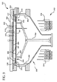
[0030]膜形成システム10の概略図が図1Aおよび図1Bに示されている。システム10は、例えばCVDエピタキシャルシステム、多結晶シリコンまたはシリコン窒化物堆積システム、あるいは、ホットCVDプロセス、つまり約400℃以上のCVDプロセス用の他の膜形成システムであってもよい。システム10は、側壁18によって境界を画定されている処理チャンバ15を含んでいる。このようなシステムの例は、共に譲渡された米国特許第5,108,792号、第5,258,824号および第6,083,323号に開示されており、これらの各々は参照して本明細書に組み込まれている。側壁18は、シリコン堆積で使用される可燃性および腐食性のプロセスガスから機器を保護するために石英から作られてもよい。基板サポートシャフト17は処理チャンバ15内に回転可能に配置されており、また、処理される基板19を置くことができる基板サポート16を含んでいる。本明細書で使用されているように、基板サポートという用語は、チャンバ15内に基板19をサポートするのに使用される任意のデバイスを含んでもよく、また、例えば、基板19の底部表面全体で基板19をサポートするサセプタ、基板19の周縁に沿ってのみ基板19をサポートするリング状サポート、基板19の底部の3つ以上のポイントで基板19をサポートする三脚状構成、基板19の縁に沿って3つ以上のポイントで基板19をサポートする構成などを含んでもよい。膜が形成されることになる基板19の上部表面は、一方では基板19の底部表面またはこの他の部分に面しているが、基板サポート16に接触している。ある実施形態によると、膜形成プロセス中は、基板サポート16は回転してもよいため、基板19を回転させることになる。一実施形態では、サセプタの形態の基板サポート16は、グラファイト、シリコンカーバイドコーティンググラファイト、固体シリコンカーバイド、アルミナおよび他の適切なセラミック材料などの、均一な特性、良好な熱伝導率(100W/m℃より良好)かつ低質量の材料から作られてもよい。
[0030] A schematic of the
[0031]処理チャンバ15の上部は上部カバー11によってシールされてもよい。上部カバー11は基板サポート16の上方、ゆえに基板19の上方に配置されている。上部カバー11は外カバー12と、内カバー14と、内カバー14に当接する反射表面13とを含んでいる。内カバー14は石英から作られてもよく、外カバー12は、比較的もろい内カバー14および側壁18を保護するために鋼から作られてもよい。反射表面13は、外カバー12と内カバー14に挟持されている、金膜や他の極めて反射的な材料から作られてもよい。複数の異なる光学スタックもまた、二酸化シリコンでカバーされているニッケルを含む反射表面13を形成してもよく、ミラー仕上げに研磨されている簡単なアルミニウム表面が使用されてもよい。反射表面13は、基板19から発せられた光を基板19に反射し返すように設計されている。より詳細に後述されるように、反射表面13は基板19の放射率効果の向上を作成する。
[0031] The top of the
[0032]ハウジング30はチャンバ15を包んでサポートする。サセプタサポートシャフト17はチャンバ15の底部アパーチャー32を介して延びている。このような延長部分によってドライブアセンブリ(図示せず)は、処理中にサセプタサポートシャフト17、ひいては基板19を回転させることができる。このような回転はプロセス均一性を高めるために達成される。
[0032] The
[0033]処理中、ガスはエントリポート34を介してチャンバ15に入り、排出ポート36を介して除去される。処理中も、放射バルブ38によって熱が提供される。放射バルブ38は、チャンバ15に近接して、ハウジング30に接続されているサポートアセンブリ40に搭載されている。チャンバ15の側壁18は透明であるため、放射バルブ38からの赤外線放射は、基板19を加熱するために反応チャンバ15に自由に入ることができる。
During processing, gas enters
[0034]処理中、石英ウィンドウ(例えば、透明なチャンバ側壁のアクセス可能な部分)は、透明であるが、依然として加熱される。チャンバ側壁18を冷却するための冷却剤流が入口導管44を介してブロワー42からハウジング30に供給されて、側壁18の外部表面を越えて向けられ、出口導管46から排出される。より特定的には、冷却剤流は、上部および下部の入口ポート48および50を通って導管44を介してハウジング30に供給される。冷却剤流は上部および下部の排出ポート52および54を通ってハウジング30を出る。ハウジング30は、チャンバ側壁18を超えて冷却剤を導くシュラウドを形成する。通常、冷却剤は空気である。空気羽根56や他の冷却剤流コントロールデバイスは入口導管44に配置されており、ハウジング30への空気流量をコントロールし、チャンバ15の側壁18の温度をコントロールする。代替的に、調整可能な虹彩、バルブ、ブロワースピードコントロール回路などの、冷却剤流をコントロールする他のデバイスが使用されてもよい。
[0034] During processing, the quartz window (eg, the accessible portion of the transparent chamber sidewall) is transparent but still heated. A coolant stream for cooling the
[0035]石英チャンバ側壁18の温度は、従来の光高温計58を使用して監視されてもよい。光高温計58は、摂氏100度〜摂氏800度の範囲の温度を測定し、かつ4.8〜5.2ミクロンの波長を検出することができるはずである。このような光高温計は、事業所の住所が7300 ノースナチェズ Avenue,Niles,III.60648のIrcon,Inc.や、事業所の住所が1290 Hammerwood Avenue,カリフォルニア州サニーベール94089のLinear Labsから入手可能である。光高温計58は基板サポート16の温度を測定するために使用されてもよく、一実施形態では、摂氏350度〜摂氏1300度の範囲の温度を測定し、かつ約905ナノメートルの波長を検出することができる。このような高温計は、例えばSekidenkoから入手可能である。905ナノメートルの波長の選択は良好な信号識別能を提供し、また基板19の温度に伴う基板19の放射率の変化を低減する。
[0035] The temperature of the
[0036]次に図1Bを参照すると、膜形成システム10はさらに、基板19から発せられた光を収集するための複数の光プローブ20を含んでいる。光プローブ20は基板19の上方に設置されており、また実質的に等しい半径方向距離で基板19の半径方向に沿って配置されてもよい。光プローブ20は外カバー12の上または中に搭載されてもよい。ある実施形態では、少なくとも4つの光プローブ20が提供されるが、光プローブ20の数は、性能を改良したりコストを低減したりするために必要ならば増減可能である。各光プローブ20は、基板19の温度を直接測定するために、反射表面13のそれぞれの開口21および外カバー12の開口22を介して基板19の上部表面に向けられる。各光プローブ20は、可能な限り多くの放射を基板19から収集するように設計されているが、基板19の縁を超える放射は監視しない、破線23で示されている拡大視界を有している。ゆえに、描かれている実施形態では、各光プローブ20の視界23は基板19内に閉じ込められており、また基板19外に延びることはない。各光プローブ20は、例えば、開口21、22内に配置され、かつ905nmの光フィルタ24に光接続されている2mmサファイア光パイプ33を備えてもよい。光パイプ33は反射表面13と同一平面で終了してもよい。当分野で知られているように、光プローブ20は、光ファイバケーブルを使用する信号処理エレクトロニクスに接続されてもよく、また光プローブ20によって収集された信号は信号処理エレクトロニクスによって対応する温度に変換可能であり、これは次いで、基板19全体に均一な温度を維持するのに必要とされる加熱電力を調整するために温度情報を使用するコントロールシステムに温度を報告する。代替的に、信号処理回路は光フィルタ24を搭載されてもよく、これは、このような構成は光ファイバケーブルと関連した信号損失を低減するため、一部の状況では望ましい場合がある。従って、光プローブ20は、基板19のそれぞれの視界23内の上部表面温度を測定する高温計として機能する。
[0036] Referring now to FIG. 1B, the
[0037]基板19を加熱するエネルギーは、基板19の下方に設置されている照射加熱システムから生じる。照射加熱システムの設計はより詳細に後述されている。
[0037] The energy for heating the
[0038]光プローブ20から取得される、高温計における潜在的に大きなエラーを導入する要因は基板19の放射率である。プランクの法則は温度と放射の関係を定量化している:
[0038] A factor that introduces a potentially large error in the pyrometer obtained from the

[0039]式1において、Φは放射電力であり、これは高温計20によって測定された実際の量である;C1およびC2は定数である;λは(上記実施形態では、例えば905nmであってもよい)放射波長である;Tは基板19の温度であり、εは基板19の放射率である。放射率が分かっている場合、プランクの法則が、基板19の温度を極めて精密に算出するために使用可能である。この放射率が分からない場合、正確な温度算出を実行するのは可能でなく、また、もたらされたエラーは、推定放射率と実際の放射率の差に応じて大きいこともある。図2は、推定放射率が1.0に設定されている場合に異なる放射率の基板19についてもたらされうる理論的温度測定エラーの大きさを示している。例えば、1.0の放射率を有すると不正確に推定して放射率0.35の基板19が測定されると、800℃でのエラーは70℃に近づくであろう。選択シリコン堆積用途については、放射率の範囲が広い基板19が処理される必要があることを予想可能であり、これらの放射率を事前に知らなくてもよい。
[0039] In
[0040]図1Bを参照して論じられているように、一実施形態は、基板19のすぐ上にある反射性の高い表面13を提供する。反射表面13は、基板19によって発光された光放射をトラップして、この光放射を、これと基板19の間を行き来するように反射し、放射率向上効果を作成する。関連する機構は図3を参照して説明されてもよい。反射表面13上に配置されている光プローブ20は、図3にΦで示されている基板19からの直接発光だけでなく、2つの表面13、19間の多数の反射も受け取る。反射表面13によって光プローブ20に達する全放射電力は:
[0040] As discussed with reference to FIG. 1B, one embodiment provides a highly
![]()
![]()
[0041]εおよびRの実数と、とりわけ1.0に近いRの値についてはεapparentは1.0になりやすいと容易に算出可能である。このことは、基板19の実際の放射率と関係なく光プローブ(または高温計)20は、1.0に近い有効放射率のターゲットを見ていることを意味する。
[0041] For the real numbers of ε and R, and particularly the value of R close to 1.0, ε apparent can be easily calculated if it tends to be 1.0. This means that regardless of the actual emissivity of the
[0042]反射表面13は従って、基板19の放射率の変動を補償する際にはかなり効果的である。図4は、放射率効果によってもたらされる温度エラーの大きさの測定を示している。図1および図5をさらに参照すると、上部表面の放射率が非常に低いテスト基板100(放射率約0.35の多結晶シリコン膜)が熱電対101によって付けられた。熱電対101は光プローブ20と同じ半径で設置されているため、2つの技術によってなされた温度測定は比較可能である。図4は、熱電対101によって測定された基板100の実際の温度の関数としての、光プローブ20によって測定された温度と熱電対101によって測定された温度の差のグラフである。図4に示されているように、放射率によるエラーは、最大850℃の温度については5℃未満である。図2を参照すると、反射表面13によって作成された高度有効放射率なしでは、放射率0.35の基板19の測定エラーは、850℃の温度では70℃を超えることが分かる。反射表面13は従って、放射率誘導エラーを90%以上低減する。
[0042] The
[0043]放射加熱された処理チャンバに高温計を使用する場合に直面するもう1つの問題は漂遊放射である。図1を参照すると、基板19は照射加熱システムを使用して加熱されてもよい。照射加熱システムは、基板19を加熱するために1つ以上のランプ38を使用する。その結果、チャンバ15は光でいっぱいになる傾向がある。この配置に伴う問題の1つは、照射加熱システムによって発生された光が、基板19によって放射された光とほとんど見分けがつかないことである。これは、高温計20はこれらのコンポーネントの両方、つまり基板19からの放射および加熱システムからの放射を収集して、基板19によって発生されたようにこの放射の全てを読み取ることを意味している。これは、摂氏数百度に容易に達しうる直接測定エラーをもたらす。例えば、図6は、ほとんどまたはまったく漂遊放射ブロッキング部材が利用されない場合の高温計温度読み取りの比較データを提供するグラフである。図6において、このデータは、チャンバが加熱時間を有することがないほど高速なレートでステップにおいて照射加熱システムのランプ電力を増大することによってとられた。熱電対によって測定された実際の基板温度は、テスト全体において140℃を超えることはなかった。高温計によって測定された、グラフに示されている表見温度の全急増は、漂遊放射によってもたらされる直接測定エラーである。図6に示されているように、このエラーは300度を超えるに達した。
[0043] Another problem encountered when using pyrometers in radiantly heated processing chambers is stray radiation. Referring to FIG. 1, the
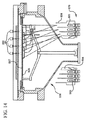
[0044]本発明の一態様は、漂遊放射と関連した問題を最小化するようにシステムコンポーネントおよび部材を提供し、本態様の実施形態は図7および8に描かれている。石英から作られてもよい側壁201によって囲まれている処理チャンバ200を含むシステムが示されている。膜形成プロセス中に基板204を保持するため使用される基板サポート202が、図1を参照して上述されたように、システム内に回転可能に配置されている。膜形成プロセスに必要なプロセス加熱の全てが照射加熱システムによって提供され、これは基板サポート202、ゆえに基板204の下方に配置されている。膜形成システムは、基板204の上方の上部領域206と、基板サポート202の下方の下部領域207との2つの領域に分割されると考えられてもよい。照射加熱システムは下部領域207にのみ設置されてもよいため、高温計(または光プローブ)が基板204の温度を測定するために設置された場合のように、照射加熱システムからの光が上部領域204に入るのを防止することが望ましい。
[0044] One aspect of the present invention provides system components and components to minimize problems associated with stray radiation, and embodiments of this aspect are depicted in FIGS. A system is shown that includes a
[0045]周辺部材205が側壁201の少なくとも一部付近に配置されている。出っ張りおよびポケットが側壁201および周辺部材205において、これら2つのコンポーネントが相互に移動しないように設計されてもよく、また周辺部材205の外周縁は側壁201の保持縁203に接触している。周辺部材205は、例えば、予熱リングであってもよい。周辺部材205はグラファイトから作られてもよく、また側壁201を介して処理チャンバに光が透過しないようにし、この処理チャンバは石英から作られてもよいため、透明または半透明であってもよい。周辺部材205は、処理チャンバ200に延びる内縁部208を備えている。この内端208は基板サポート202の外端209と重複する。ゆえに、周辺部材205および基板サポート202はそれぞれ重複する内外の端部208、209を有する。ギャップ210が、回転する基板サポート202と静止している周辺部材205間に提供されてもよい。ギャップ210の幅は、重複する端208、209を分離しており、ギャップ210を通過する光の量を最小に保つために可能な限り小さく作られてもよく、一実施形態では、幅0.075インチである。1セットの重複表面208、209を提供することによって、下部領域207から発せられた光の大部分は上部領域206に入るのをブロックされる。重複表面208、209は、基板サポート202の外周縁および周辺部材205の内周縁にステップ付き部材を含んでもよい。基板サポート202および周辺部材205のステップ付き部材は相補的なものとして示されている。基板サポート202の外周縁209と周辺部材205の内周縁208間に相補的ステップ付き設計を提供することによって、内周縁208の上部表面は基板サポート202の上部表面より高くならないことが注目される。
[0045] A
[0046]下部領域207からの光がギャップ210を介して上部領域206に逃げるのをさらに防止するために、重複表面208、209は、光を分散および吸収するように設計されている光学的に粗い仕上げで提供されることがある。例えば、基板サポート202の外端209の上部表面は、一連のより狭い溝211を提供するように加工されてもよい。周辺部材205の内端208の底部表面は同様に溝付き表面が提供されてもよい。溝が使用されてはいるが、他のタイプの角度付き表面や、照射加熱システムによって発光された放射を吸収するように設計されている光学膜などの、光を吸収する任意の適切な表面が重複表面208、209に使用されてもよい点が理解されるべきである。
[0046] To further prevent light from the
[0047]漂遊放射をさらにブロックするために、図7および8に描かれている実施形態はさらに、上部周辺部材、つまり光シールド212を提供する。上部光シールド212はグラファイトから作られてもよく、また周辺部材205およびサセプタ202の重複端208、209の上方に配置される。上部光シールド212は上部側壁213上に、またはこれに隣接して配置されてもよい。上部側壁213は石英から作られてもよい。出っ張りおよびポケットは、上部側壁213および光シールド212において、これら2つのコンポーネントが相互に移動しないように設計されてもよい。ギャップ215が、サセプタ202の回転と干渉しないようにするために、上部光シールド212の下部表面214を基板サポート202および周辺部材205の上部表面から分離してもよい。上部光シールド212の下部表面214は同様に、ギャップ210から発せられた光を吸収するために、一連の細い溝や光活性膜などの光学的に粗い、または吸収性の表面を提供されてもよい。上部光シールド212は側壁201、213の周縁全体に沿ってもよい。別個の要素として描かれているが、上部側壁213および下部側壁201は、周辺部材205を受容するように適切な溝などによって製造されたモノリシック要素から作られてもよい。
[0047] To further block stray radiation, the embodiment depicted in FIGS. 7 and 8 further provides an upper peripheral member, or
[0048]図9は、石英側壁302および上部カバー303によって境界を画定されている処理チャンバ301を備える別の膜形成システム300を図示する。基板サポートシャフト304は処理チャンバ301内に回転可能に配置されており、また基板306を保持するサセプタ305を備えている。サセプタ305は、グラファイトや固体シリコンカーバイドなどの、少なくとも100W/m℃の熱伝導率を有する軽くて、均一かつ熱伝導性の材料から作られており、基板306の底部表面を完全にカバーしており、また伝導および放射によって基板306を加熱するように設計されている。上部カバー303は、石英の内層308と鋼の外層309の間に挟持されている反射表面307を備える。反射表面307は、基板306から発せられた放射を基板306の上部表面に反射し返して、基板306の有効放射率を増大させる。
FIG. 9 illustrates another
[0049]この放射率向上効果によって、基板306の表面上の反射率の値やパターンに関係なく基板306が均一かつ等温条件に達するまで、反射表面307は基板306にエネルギーを一定に反射し返す。基板306の温度の高温測定を提供するために、複数の光プローブ310が基板306から発せられた光をサンプリングし、各光プローブ310は、基板306を超えては延びないそれぞれの視界311を有している。反射表面307の開口312はそれぞれの視界311を光プローブ310に提供してもよい。
[0049] Due to this emissivity enhancement effect, the
[0050]膜形成システム300は、基板サポート305の下方に配置されている加熱システム313を備えている。加熱システム313は1つ以上のランプ314を備えており、これは、チャンバ301に下から光を放射して基板サポート305の底部を加熱する。全てのプロセス加熱が加熱システム313によって提供される。ランプ314からの光が光プローブ310に達するのを防止するために、システム300はさらに、サセプタ305と重複する予熱リングであってもよいグラファイト周辺部材315を備えている。従って、上記実施形態で開示されているように、サセプタ305と周辺部材315間に重複領域316が存在する。この重複領域316内の表面は、サセプタ304を周辺部材315から分離するギャップを介して分散する光をより良好に吸収するために、例えば細い溝や光学薄膜によって、光学的に粗く、または吸収性にされてもよい。グラファイト上部周辺部材、つまり光シールド317はまた、ランプ314から分散する光をさらにブロックするために、重複領域316の上方に配置されてもよい。光シールド317は石英上部側壁318によってサポートされてもよい。
[0050] The
[0051]膜形成システム300は、基板306のパターン負荷および放射率変動によって通常はもたらされる膜形成プロセスの欠陥を防止するように設計されている。サセプタ305は加熱システム313に一定の吸収率ターゲットを提供する。加熱システム313は従ってサセプタ305を均一に加熱することによって、これがまた基板306を均一に導電加熱し、また反射表面307によって、パターン負荷および放射率効果を回避するために基板306全体に等温条件を保証する。反射表面307は2つの別個の機能を提供する:1)基板306の大域的放射率とは関係なくプローブ310に基板306の温度を正確に測定させ、また2)基板306の放射率の局所的かつナノスケールの変化によってもたらされるパターン負荷効果を低減するのに役立つ。
[0051] The
[0052]図10は、膜形成システム300の高温計温度データ対熱電対温度データの実験結果を図示しているグラフである。光プローブ310によって測定された高温計温度を検証するために、上部表面に4つの熱電対が溶接されている、図5に描かれているものと類似の特殊ウェーハが利用された。これらの熱電対は光プローブ310の下方に直接設置されたため、光プローブ310の高温計読み取りは直接比較可能である。(約0.95の)高放射率膜が、熱電対を取り付ける前にウェーハの表面上で成長された。これによって、光プローブ310の精度および反復性は、任意の熱サイクルでウェーハを加熱して、かつ熱電対読み取りを、光プローブ310でなされたものと比較することによってテストされた。基板の中心付近に設置されている熱電対および光プローブをグラフ化している図10に示されているように、システム300は、熱電対で測定された温度と、光プローブ310を介して高温計で測定された温度との密接な相関関係を提供する。
[0052] FIG. 10 is a graph illustrating experimental results of pyrometer temperature data versus thermocouple temperature data for
[0053]図11は、これらのテスト中に取得された実際のチャンバ310の温度の関数としての全光プローブ310の平均測定エラー算出の概要を示している。示されているように、対象の温度範囲(>550℃)について、漂遊光によるエラーは2℃程度である。
[0053] FIG. 11 shows an overview of the average measurement error calculation of the all-
[0054]高温計測定の放射率有効補正をさらに提供する膜形成システム400の別の実施形態が図12に示されている。膜形成システム40は図9のシステム300と類似しているが、しかしながら、システム400はさらに、基板420の実際の放射率を測定するための放射計410を含んでいる。放射計410の動作原理は、光プローブ403をチャンバ402に位置決めするステップを伴うが、この光プローブ403については、反射表面401によって提供された高度有効放射率が低減または排除される。光プローブ403は、放射の反射なしに、基板420からの直接放射を見るにすぎない。つまり、光プローブ403の放射電力の測定は次式の通りである。
[0054] Another embodiment of a
[0055]光プローブ403で測定された温度を、反射表面401の完全高度放射率効果を経験する近接する光プローブ404で測定されたものと比較することによって、基板420の実際の放射率を算出することが可能である。例えば、基板420の放射率は以下のように算出可能である:
[0055] The actual emissivity of the
ここでTmeasは測定されたウェーハ温度であり、デルタは温度プローブ404および放射計プローブ403によって測定された温度差であり、R3は反射表面401の反射率であり、REは放射計410付近のキャビティの反射率である。式1におけるように他の定数は所与のものである。代替的に、0.3〜約0.95の既知の反射率の複数の基板420はチャンバ402で稼動されてもよく、また放射計410と標準高温計404間の温度差分が較正曲線を構築するために測定されてもよい。この較正曲線は指数関数と一致することもあり、そして引き続き未知の基板420の放射率を判断するのに使用される。この放射率値は次いで、高温光プローブ405によって報告された温度に補正を実行するのに使用される。
Where Tmeas is the measured wafer temperature, delta is the temperature difference measured by temperature probe 404 and
[0056]図13は放射計410の実施形態を図示している。光プローブ403は、比較的大きな直径のホール406がドリルであけられているかエッチングされている反射表面401のエリアに配置されている。ホール406の直径は、光プローブ403の視界、および基板420までの距離と相関することもある。反射表面401から反射されずに基板420から直接来る光を光プローブ403が収集することによって、光プローブ403が反射表面401によって提供された放射率向上を何ら受け取らないことが望ましい。ゆえに、ホール406の直径が可能な限り広いことが望ましい。しかしながら、基板420がほぼ全ての角度で放射を発光するため、ホール406が非常に大きくされなければ、光プローブ403は一部の放射率向上放射をほぼ常に収集する。ホール406を非常に大きくすることは望ましくないが、これは、基板420上にコールドスポットを作成する傾向があるからである。基板420か回転可能であるため、このコールドスポットは基板420上にコールドリングを作成することになる。ホール406の直径を、光プローブ403の基板420の表面上の視界と同じサイズにすることによって適切な妥協策が提供されてもよい。一実施形態では、ホール406の直径は0.5インチ〜2インチに及ぶことがある。別の実施形態では、この直径は約0.75インチである。一般的に、単純な三角法が使用されてもよく、またこの直径は、光プローブ403の視界の角度と、光プローブ403および基板420からの距離との関数であってもよい。ホール406の幅は、このプローブ403に達する放射の反射表面401の放射率向上効果を効果的に排除する。反射表面401の大きなホール406が基板420の温度に良くない効果を与えるのを防止するために、ホットミラー407がホール406をカバーするように位置決めされている。ホットミラー407は軸外光を基板420に反射し返すように設計されており、このことは、ホール406による熱損失量を最小化する。このようなホットミラーは、例えばSekidenkoから取得可能である。ホットミラー407ゆえに、プローブ403のすぐ下に発光される放射のみが放射計410に達する。この放射は反射表面401によって向上されるのではなく、そして、上記のように、基板420の放射率を計算するために標準の高温プローブ404、405と比較可能である。基板420の放射率が分かっている場合、基板420の温度は、式1と、光プローブ404、405によって検出された放射電力とによって正確に判断可能である。
[0056] FIG. 13 illustrates an embodiment of a
[0057]当然、任意の適切な放射計が使用されてもよい。例えば、基板の放射率を取得するために反射率計が使用されてもよい。当分野で知られているように、反射率計は光ビームを基板に送り、反射強度を測定する。光の波長を適切に選択することによって、基板はいずれの光も透過させず、光の一部を反射し返すことになる。反射光の強度は測定可能であり、これによって基板の放射率の直接測定が取得可能であるが、これは、放射率=1−反射率であるためである。このような反射率計は市販されており、例えばCl Systems at 30961 West Agoura Road,Suite 109,ウェストレイクビレッジ,CA91361−4618から取得可能である。 [0057] Of course, any suitable radiometer may be used. For example, a reflectometer may be used to obtain the emissivity of the substrate. As is known in the art, a reflectometer sends a light beam to a substrate and measures the reflected intensity. By appropriately selecting the wavelength of light, the substrate does not transmit any light and reflects part of the light back. The intensity of the reflected light can be measured, thereby obtaining a direct measurement of the emissivity of the substrate, because emissivity = 1−reflectance. Such reflectometers are commercially available and can be obtained, for example, from Cl Systems at 30961 West Agoura Road, Suite 109, Westlake Village, CA 91361-4618.
[0058]付加的に、対応する複数の領域にわたって基板の放射率を判断するために、各々が基板のそれぞれの視界を具備している複数の放射計を利用することが可能である。ある領域の基板の放射率は、その領域について放射計によって測定されたように、次いで、この領域を包含する視界を具備する対応する高温計について当該領域の温度を正確に計算するために使用されてもよい。このように、基板全体の温度分布はより正確に測定可能であり、ゆえにより正確にコントロール可能である。 [0058] Additionally, a plurality of radiometers, each with a respective field of view of the substrate, can be utilized to determine the emissivity of the substrate over a corresponding plurality of regions. The substrate emissivity of an area is then used to accurately calculate the temperature of that area for the corresponding pyrometer with a field of view encompassing this area, as measured by the radiometer for that area. May be. In this way, the temperature distribution of the entire substrate can be measured more accurately and can therefore be controlled more accurately.
[0059]別の実施形態によると、調整可能なエネルギーソースが、膜形成チャンバ内の温度をコントロールするために提供される。次に図14を参照すると、システム500が、4ゾーンの照射加熱システム510を含んでおり、各ゾーン501は、高温光プローブ502の対応する放射分布から受け取られた温度フィードバックに基づいて独立して調整され可能である。照射加熱システム510はサセプタ505の下方に配置されており、複数のランプ503および反射計504を備えている。ランプ503および反射計504の角度および配向の調整は、独立して調整可能な加熱ゾーン501を作成する。
[0059] According to another embodiment, an adjustable energy source is provided to control the temperature within the film formation chamber. Referring now to FIG. 14, the
[0060]加熱ゾーン501は、サセプタ505の底部表面全体に均一であるように調整可能な加熱パターンを発生させるために結合する。サセプタ505の底部表面は、例えば光学膜、溝などを利用することによって、ランプ503によって発光された放射を最大限吸収するように設計されてもよい。加熱システム510によって生成された加熱パターンのグラフが図15に提示されており、独立してONにされた場合の個別加熱ゾーン501ごとにサセプタ505で測定された熱分布を示している。各加熱ゾーン501は、サセプタ505上の特定の半径で(つまり、各ゾーン501の加熱分布はサセプタ505の回転中心に対して対称である)、ゆえに基板507上の特定の半径で基板507を加熱し、また全ての加熱ゾーン501は、均一な加熱分布を作成するのに十分に重複している。図15に示されている加熱パターンの加熱ゾーン501が、1σ当たり1℃より良好な基板507全体の温度分布を発生させるために重なることが予想されている。さらに、上述のように、基板507を底部から加熱することだけが、放射率およびパターン負荷の効果を直接低減する。
[0060] The
[0061]上記は本発明の実施形態を目的としているが、本発明の他のさらなる実施形態がこの基本的範囲から逸脱することなく考案されてもよく、またはこの範囲は以下の特許請求の範囲によって判断される。 [0061] While the above is directed to embodiments of the present invention, other and further embodiments of the invention may be devised without departing from the basic scope thereof, or the scope of the claims which follow. Is judged by.
10…膜形成システム、11…上部カバー、12…外カバー、13…反射表面、14…内カバー、15…処理チャンバ、16…基板サポート、17…基板サポートシャフト、18…側壁、19…基板、20…光プローブ、21…開口、22…開口、23…視界、24…光フィルタ、30…ハウジング、32…底部アパーチャー、33…光パイプ、34…エントリポート、36…排出ポート、38…放射バルブ、40…サポートアセンブリ、42…ブロワー、44…入口導管、48…上部入口ポート、50…下部入口ポート、101…熱電対、200…処理チャンバ、201…側壁、203…保持縁、204…基板、205…周辺部材、206…上部領域、207…下部領域、208…内端、209…外端、210…ギャップ、211…溝、212…上部光シールド、213…上部側壁、214…下部表面、215…ギャップ、300…膜形成システム、301…処理チャンバ、302…側壁、303…上部カバー、304…基板サポートシャフト、305…サセプタ、306…基板、310…光プローブ、311…視界、312…開口、313…加熱システム、314…ランプ、315…周辺部材、316…重複領域、317…光シールド、400…膜形成システム、401…反射表面、402…チャンバ、403…光プローブ、404…高温計、405…高温光プローブ、406…ホール、407…ホットミラー、410…放射計、420…基板、500…システム、501…加熱ゾーン、502…高温光プローブ、503…ランプ、504…反射計、505…サセプタ、507…基板、510…照射加熱システム
DESCRIPTION OF
Claims (15)
基板上に膜を形成するように適合されている処理チャンバであって、前記チャンバの周辺を囲む側壁を含む処理チャンバと、
前記システムに配置されており、かつ前記基板をサポートするように適合されている基板サポートと、
前記処理チャンバを包囲するように前記基板サポートの上方に配置されている上部カバーであって、前記基板サポートに向かって光を反射し返すための反射表面を備える上部カバーと、
膜形成プロセスに十分な温度に前記基板を加熱するために前記基板サポートの下方に配置されている加熱システムであって、前記基板のプロセス加熱が前記加熱システムによってのみ実行される加熱システムと、
前記反射表面に設けられた複数の開口を介して、前記基板から発せられた放射と、前記反射表面と前記基板とにより反射された放射と、が含まれた放射を測定する複数の光プローブと、
前記基板から発せられた放射のみを測定し、当該測定した放射と前記複数の光プローブのうちの少なくとも1つにより測定された放射に基づき前記基板の実際の放射率を算出する放射計と、を備え、
前記基板の温度が、前記算出された放射率と前記複数の光プローブのうち少なくとも1つの光プローブにより測定された放射とに基づき算出される、基板処理システム。 A substrate processing system,
A processing chamber adapted to form a film on a substrate, the processing chamber including a sidewall surrounding the periphery of the chamber;
A substrate support disposed in the system and adapted to support the substrate;
An upper cover disposed above the substrate support so as to surround the processing chamber, the upper cover comprising a reflective surface for reflecting light back toward the substrate support;
A heating system disposed below the substrate support to heat the substrate to a temperature sufficient for a film forming process, wherein the process heating of the substrate is performed only by the heating system;
A plurality of optical probes for measuring radiation including radiation emitted from the substrate and radiation reflected by the reflective surface and the substrate through a plurality of openings provided in the reflective surface; ,
A radiometer to calculate the actual emissivity of the substrate on the basis of the measured emitted by at least one of said only emitted et radiation from the substrate was measured, the radiation and the plurality of light probes the measurement, With
The substrate processing system, wherein the temperature of the substrate is calculated based on the calculated emissivity and radiation measured by at least one optical probe of the plurality of optical probes.
前記光プローブが高温計である、請求項1に記載の基板処理システム。 The field of view of any optical probe does not extend beyond the substrate,
The substrate processing system according to claim 1, wherein the optical probe is a pyrometer.
前記光プローブが前記基板の上方におよそ等距離に放射状に間隔をあけられている、
請求項1に記載の基板処理システム。 The optical probe is optically connected to signal processing electronics;
The optical probes are radially spaced approximately equidistant above the substrate;
The substrate processing system according to claim 1.
前記反射表面における開口と、
前記開口をカバーするホットミラーと、
前記基板から発せられた光を収集して前記ホットミラーを通過する光プローブと、
を備える、請求項1に記載の基板処理システム。 The radiometer
An opening in the reflective surface;
A hot mirror covering the opening;
An optical probe that collects light emitted from the substrate and passes through the hot mirror;
The substrate processing system according to claim 1, comprising:
前記基板サポートが前記システムに回転可能に搭載されており、また前記外縁部が前記内周縁に接触していない、請求項1に記載の基板処理システム。 An inner peripheral edge that contacts the first edge of the side wall and extends to the processing chamber that overlaps the outer edge of the substrate support to prevent light from the heating system from reaching the top cover. A peripheral member having
The substrate processing system according to claim 1, wherein the substrate support is rotatably mounted on the system, and the outer edge portion is not in contact with the inner peripheral edge.
前記側壁に隣接しており、かつ前記内周縁および前記外縁部と重複するように前記処理チャンバに延びている第2の周辺部材をさらに備える、請求項6に記載の基板処理システム。 The surface of the inner peripheral edge facing the outer edge comprises a roughened surface;
The substrate processing system according to claim 6, further comprising a second peripheral member adjacent to the side wall and extending to the processing chamber so as to overlap the inner peripheral edge and the outer edge.
第1の測定を提供するために、処理中に前記基板からのみ発光された放射を測定するステップと、
第2の測定を提供するために、前記処理チャンバから反射され、かつ前記基板から発光された放射を測定するステップと、
前記第1の測定および第2の測定に基づき、前記基板の実際の放射率を算出するステップと、
前記算出された放射率に基づき前記第2の測定を補正し、前記基板の温度値を取得するステップと、を備える方法。 A method of measuring temperature in a processing chamber adapted to form a film on a substrate surface, comprising:
Measuring radiation emitted only from the substrate during processing to provide a first measurement;
Measuring radiation reflected from the processing chamber and emitted from the substrate to provide a second measurement;
Calculating an actual emissivity of the substrate based on the first measurement and the second measurement;
Correcting the second measurement based on the calculated emissivity and obtaining a temperature value of the substrate.
Applications Claiming Priority (3)
| Application Number | Priority Date | Filing Date | Title |
|---|---|---|---|
| US11/242,298 US7691204B2 (en) | 2005-09-30 | 2005-09-30 | Film formation apparatus and methods including temperature and emissivity/pattern compensation |
| US11/242,298 | 2005-09-30 | ||
| PCT/US2006/035031 WO2007040908A2 (en) | 2005-09-30 | 2006-09-11 | Film formation apparatus and methods including temperature and emissivity/pattern compensation |
Publications (3)
| Publication Number | Publication Date |
|---|---|
| JP2009510262A JP2009510262A (en) | 2009-03-12 |
| JP2009510262A5 JP2009510262A5 (en) | 2009-09-10 |
| JP5686952B2 true JP5686952B2 (en) | 2015-03-18 |
Family
ID=37902229
Family Applications (1)
| Application Number | Title | Priority Date | Filing Date |
|---|---|---|---|
| JP2008533387A Expired - Fee Related JP5686952B2 (en) | 2005-09-30 | 2006-09-11 | Film forming apparatus and method including temperature and emissivity / pattern compensation |
Country Status (5)
| Country | Link |
|---|---|
| US (1) | US7691204B2 (en) |
| JP (1) | JP5686952B2 (en) |
| KR (1) | KR101047089B1 (en) |
| TW (1) | TWI367958B (en) |
| WO (1) | WO2007040908A2 (en) |
Families Citing this family (370)
| Publication number | Priority date | Publication date | Assignee | Title |
|---|---|---|---|---|
| CN100565786C (en) * | 2002-12-09 | 2009-12-02 | Nxp股份有限公司 | The system and method that in the cold wall CVD system, suppresses the chip temperature skew |
| US7691204B2 (en) * | 2005-09-30 | 2010-04-06 | Applied Materials, Inc. | Film formation apparatus and methods including temperature and emissivity/pattern compensation |
| US8372203B2 (en) * | 2005-09-30 | 2013-02-12 | Applied Materials, Inc. | Apparatus temperature control and pattern compensation |
| US8986456B2 (en) * | 2006-10-10 | 2015-03-24 | Asm America, Inc. | Precursor delivery system |
| WO2009120859A1 (en) * | 2008-03-26 | 2009-10-01 | Gt Solar, Inc. | Gold-coated polysilicon reactor system and method |
| US8726837B2 (en) * | 2008-06-23 | 2014-05-20 | Applied Materials, Inc. | Semiconductor process chamber vision and monitoring system |
| US8111978B2 (en) * | 2008-07-11 | 2012-02-07 | Applied Materials, Inc. | Rapid thermal processing chamber with shower head |
| US10378106B2 (en) | 2008-11-14 | 2019-08-13 | Asm Ip Holding B.V. | Method of forming insulation film by modified PEALD |
| EP2409321A4 (en) * | 2009-03-16 | 2013-07-24 | Alta Devices Inc | Reactor lid assembly for vapor deposition |
| US20100248397A1 (en) * | 2009-03-26 | 2010-09-30 | Tokyo Electron Limited | High temperature susceptor having improved processing uniformity |
| US9394608B2 (en) | 2009-04-06 | 2016-07-19 | Asm America, Inc. | Semiconductor processing reactor and components thereof |
| US8802201B2 (en) | 2009-08-14 | 2014-08-12 | Asm America, Inc. | Systems and methods for thin-film deposition of metal oxides using excited nitrogen-oxygen species |
| US8877655B2 (en) | 2010-05-07 | 2014-11-04 | Asm America, Inc. | Systems and methods for thin-film deposition of metal oxides using excited nitrogen-oxygen species |
| US8883270B2 (en) * | 2009-08-14 | 2014-11-11 | Asm America, Inc. | Systems and methods for thin-film deposition of metal oxides using excited nitrogen—oxygen species |
| CN102041486A (en) * | 2009-10-23 | 2011-05-04 | 周星工程股份有限公司 | Substrate processing equipment |
| US9869021B2 (en) | 2010-05-25 | 2018-01-16 | Aventa Technologies, Inc. | Showerhead apparatus for a linear batch chemical vapor deposition system |
| US9169562B2 (en) | 2010-05-25 | 2015-10-27 | Singulus Mocvd Gmbh I. Gr. | Parallel batch chemical vapor deposition system |
| US8986451B2 (en) | 2010-05-25 | 2015-03-24 | Singulus Mocvd Gmbh I. Gr. | Linear batch chemical vapor deposition system |
| TW201218301A (en) * | 2010-10-28 | 2012-05-01 | Applied Materials Inc | Apparatus having improved substrate temperature uniformity using direct heating methods |
| US8967860B2 (en) | 2011-02-07 | 2015-03-03 | Applied Materials, Inc. | Low temperature measurement and control using low temperature pyrometry |
| US9312155B2 (en) | 2011-06-06 | 2016-04-12 | Asm Japan K.K. | High-throughput semiconductor-processing apparatus equipped with multiple dual-chamber modules |
| US9793148B2 (en) | 2011-06-22 | 2017-10-17 | Asm Japan K.K. | Method for positioning wafers in multiple wafer transport |
| US10364496B2 (en) | 2011-06-27 | 2019-07-30 | Asm Ip Holding B.V. | Dual section module having shared and unshared mass flow controllers |
| US10854498B2 (en) | 2011-07-15 | 2020-12-01 | Asm Ip Holding B.V. | Wafer-supporting device and method for producing same |
| US20130023129A1 (en) | 2011-07-20 | 2013-01-24 | Asm America, Inc. | Pressure transmitter for a semiconductor processing environment |
| DE102011083245B4 (en) * | 2011-09-22 | 2019-04-25 | Siltronic Ag | Method and device for depositing an epitaxial layer of silicon on a semiconductor wafer of monocrystalline silicon by vapor deposition in a process chamber |
| US9096931B2 (en) | 2011-10-27 | 2015-08-04 | Asm America, Inc | Deposition valve assembly and method of heating the same |
| US9341296B2 (en) | 2011-10-27 | 2016-05-17 | Asm America, Inc. | Heater jacket for a fluid line |
| US9017481B1 (en) | 2011-10-28 | 2015-04-28 | Asm America, Inc. | Process feed management for semiconductor substrate processing |
| US9167625B2 (en) | 2011-11-23 | 2015-10-20 | Asm Ip Holding B.V. | Radiation shielding for a substrate holder |
| US9005539B2 (en) | 2011-11-23 | 2015-04-14 | Asm Ip Holding B.V. | Chamber sealing member |
| US9202727B2 (en) | 2012-03-02 | 2015-12-01 | ASM IP Holding | Susceptor heater shim |
| US9682398B2 (en) | 2012-03-30 | 2017-06-20 | Applied Materials, Inc. | Substrate processing system having susceptorless substrate support with enhanced substrate heating control |
| US8946830B2 (en) | 2012-04-04 | 2015-02-03 | Asm Ip Holdings B.V. | Metal oxide protective layer for a semiconductor device |
| US9905444B2 (en) * | 2012-04-25 | 2018-02-27 | Applied Materials, Inc. | Optics for controlling light transmitted through a conical quartz dome |
| US10202707B2 (en) * | 2012-04-26 | 2019-02-12 | Applied Materials, Inc. | Substrate processing system with lamphead having temperature management |
| TWI622664B (en) | 2012-05-02 | 2018-05-01 | Asm智慧財產控股公司 | Phase-stabilized thin films, structures and devices including the thin films, and methods of forming same |
| US8728832B2 (en) | 2012-05-07 | 2014-05-20 | Asm Ip Holdings B.V. | Semiconductor device dielectric interface layer |
| US9200965B2 (en) * | 2012-06-26 | 2015-12-01 | Veeco Instruments Inc. | Temperature control for GaN based materials |
| US8933375B2 (en) | 2012-06-27 | 2015-01-13 | Asm Ip Holding B.V. | Susceptor heater and method of heating a substrate |
| US9558931B2 (en) | 2012-07-27 | 2017-01-31 | Asm Ip Holding B.V. | System and method for gas-phase sulfur passivation of a semiconductor surface |
| US9117866B2 (en) | 2012-07-31 | 2015-08-25 | Asm Ip Holding B.V. | Apparatus and method for calculating a wafer position in a processing chamber under process conditions |
| US9659799B2 (en) | 2012-08-28 | 2017-05-23 | Asm Ip Holding B.V. | Systems and methods for dynamic semiconductor process scheduling |
| US9169975B2 (en) | 2012-08-28 | 2015-10-27 | Asm Ip Holding B.V. | Systems and methods for mass flow controller verification |
| US9021985B2 (en) | 2012-09-12 | 2015-05-05 | Asm Ip Holdings B.V. | Process gas management for an inductively-coupled plasma deposition reactor |
| US9324811B2 (en) | 2012-09-26 | 2016-04-26 | Asm Ip Holding B.V. | Structures and devices including a tensile-stressed silicon arsenic layer and methods of forming same |
| US10714315B2 (en) | 2012-10-12 | 2020-07-14 | Asm Ip Holdings B.V. | Semiconductor reaction chamber showerhead |
| US9640416B2 (en) | 2012-12-26 | 2017-05-02 | Asm Ip Holding B.V. | Single-and dual-chamber module-attachable wafer-handling chamber |
| US20160376700A1 (en) | 2013-02-01 | 2016-12-29 | Asm Ip Holding B.V. | System for treatment of deposition reactor |
| US8894870B2 (en) | 2013-02-01 | 2014-11-25 | Asm Ip Holding B.V. | Multi-step method and apparatus for etching compounds containing a metal |
| US9748121B2 (en) | 2013-03-05 | 2017-08-29 | Applied Materials, Inc. | Thermal coupled quartz dome heat sink |
| US9589770B2 (en) | 2013-03-08 | 2017-03-07 | Asm Ip Holding B.V. | Method and systems for in-situ formation of intermediate reactive species |
| US9484191B2 (en) | 2013-03-08 | 2016-11-01 | Asm Ip Holding B.V. | Pulsed remote plasma method and system |
| KR20160003099A (en) * | 2013-04-26 | 2016-01-08 | 어플라이드 머티어리얼스, 인코포레이티드 | Absorbing lamphead face |
| US9842753B2 (en) | 2013-04-26 | 2017-12-12 | Applied Materials, Inc. | Absorbing lamphead face |
| US8993054B2 (en) | 2013-07-12 | 2015-03-31 | Asm Ip Holding B.V. | Method and system to reduce outgassing in a reaction chamber |
| US9018111B2 (en) | 2013-07-22 | 2015-04-28 | Asm Ip Holding B.V. | Semiconductor reaction chamber with plasma capabilities |
| US9814099B2 (en) * | 2013-08-02 | 2017-11-07 | Applied Materials, Inc. | Substrate support with surface feature for reduced reflection and manufacturing techniques for producing same |
| US9396934B2 (en) | 2013-08-14 | 2016-07-19 | Asm Ip Holding B.V. | Methods of forming films including germanium tin and structures and devices including the films |
| US9793115B2 (en) | 2013-08-14 | 2017-10-17 | Asm Ip Holding B.V. | Structures and devices including germanium-tin films and methods of forming same |
| US9240412B2 (en) | 2013-09-27 | 2016-01-19 | Asm Ip Holding B.V. | Semiconductor structure and device and methods of forming same using selective epitaxial process |
| US9556516B2 (en) | 2013-10-09 | 2017-01-31 | ASM IP Holding B.V | Method for forming Ti-containing film by PEALD using TDMAT or TDEAT |
| US9605343B2 (en) | 2013-11-13 | 2017-03-28 | Asm Ip Holding B.V. | Method for forming conformal carbon films, structures conformal carbon film, and system of forming same |
| US10179947B2 (en) | 2013-11-26 | 2019-01-15 | Asm Ip Holding B.V. | Method for forming conformal nitrided, oxidized, or carbonized dielectric film by atomic layer deposition |
| DE102013114412A1 (en) | 2013-12-18 | 2015-06-18 | Aixtron Se | Apparatus and method for controlling the temperature in a process chamber of a CVD reactor using two temperature sensor means |
| US11015244B2 (en) | 2013-12-30 | 2021-05-25 | Advanced Material Solutions, Llc | Radiation shielding for a CVD reactor |
| US10683571B2 (en) | 2014-02-25 | 2020-06-16 | Asm Ip Holding B.V. | Gas supply manifold and method of supplying gases to chamber using same |
| US10167557B2 (en) | 2014-03-18 | 2019-01-01 | Asm Ip Holding B.V. | Gas distribution system, reactor including the system, and methods of using the same |
| US9447498B2 (en) | 2014-03-18 | 2016-09-20 | Asm Ip Holding B.V. | Method for performing uniform processing in gas system-sharing multiple reaction chambers |
| US11015245B2 (en) | 2014-03-19 | 2021-05-25 | Asm Ip Holding B.V. | Gas-phase reactor and system having exhaust plenum and components thereof |
| US9404587B2 (en) | 2014-04-24 | 2016-08-02 | ASM IP Holding B.V | Lockout tagout for semiconductor vacuum valve |
| US10858737B2 (en) | 2014-07-28 | 2020-12-08 | Asm Ip Holding B.V. | Showerhead assembly and components thereof |
| US9543180B2 (en) | 2014-08-01 | 2017-01-10 | Asm Ip Holding B.V. | Apparatus and method for transporting wafers between wafer carrier and process tool under vacuum |
| US9890456B2 (en) | 2014-08-21 | 2018-02-13 | Asm Ip Holding B.V. | Method and system for in situ formation of gas-phase compounds |
| US9657845B2 (en) | 2014-10-07 | 2017-05-23 | Asm Ip Holding B.V. | Variable conductance gas distribution apparatus and method |
| US10941490B2 (en) | 2014-10-07 | 2021-03-09 | Asm Ip Holding B.V. | Multiple temperature range susceptor, assembly, reactor and system including the susceptor, and methods of using the same |
| KR102300403B1 (en) | 2014-11-19 | 2021-09-09 | 에이에스엠 아이피 홀딩 비.브이. | Method of depositing thin film |
| KR102263121B1 (en) | 2014-12-22 | 2021-06-09 | 에이에스엠 아이피 홀딩 비.브이. | Semiconductor device and manufacuring method thereof |
| US9478415B2 (en) | 2015-02-13 | 2016-10-25 | Asm Ip Holding B.V. | Method for forming film having low resistance and shallow junction depth |
| US10529542B2 (en) | 2015-03-11 | 2020-01-07 | Asm Ip Holdings B.V. | Cross-flow reactor and method |
| US10276355B2 (en) | 2015-03-12 | 2019-04-30 | Asm Ip Holding B.V. | Multi-zone reactor, system including the reactor, and method of using the same |
| US20160282886A1 (en) * | 2015-03-27 | 2016-09-29 | Applied Materials, Inc. | Upper dome temperature closed loop control |
| US10458018B2 (en) | 2015-06-26 | 2019-10-29 | Asm Ip Holding B.V. | Structures including metal carbide material, devices including the structures, and methods of forming same |
| US10600673B2 (en) | 2015-07-07 | 2020-03-24 | Asm Ip Holding B.V. | Magnetic susceptor to baseplate seal |
| US9899291B2 (en) | 2015-07-13 | 2018-02-20 | Asm Ip Holding B.V. | Method for protecting layer by forming hydrocarbon-based extremely thin film |
| US10043661B2 (en) | 2015-07-13 | 2018-08-07 | Asm Ip Holding B.V. | Method for protecting layer by forming hydrocarbon-based extremely thin film |
| US10083836B2 (en) | 2015-07-24 | 2018-09-25 | Asm Ip Holding B.V. | Formation of boron-doped titanium metal films with high work function |
| US10087525B2 (en) | 2015-08-04 | 2018-10-02 | Asm Ip Holding B.V. | Variable gap hard stop design |
| US9647114B2 (en) | 2015-08-14 | 2017-05-09 | Asm Ip Holding B.V. | Methods of forming highly p-type doped germanium tin films and structures and devices including the films |
| US9711345B2 (en) | 2015-08-25 | 2017-07-18 | Asm Ip Holding B.V. | Method for forming aluminum nitride-based film by PEALD |
| US9960072B2 (en) | 2015-09-29 | 2018-05-01 | Asm Ip Holding B.V. | Variable adjustment for precise matching of multiple chamber cavity housings |
| US9909214B2 (en) | 2015-10-15 | 2018-03-06 | Asm Ip Holding B.V. | Method for depositing dielectric film in trenches by PEALD |
| US10211308B2 (en) | 2015-10-21 | 2019-02-19 | Asm Ip Holding B.V. | NbMC layers |
| US10322384B2 (en) | 2015-11-09 | 2019-06-18 | Asm Ip Holding B.V. | Counter flow mixer for process chamber |
| US9455138B1 (en) | 2015-11-10 | 2016-09-27 | Asm Ip Holding B.V. | Method for forming dielectric film in trenches by PEALD using H-containing gas |
| US9905420B2 (en) | 2015-12-01 | 2018-02-27 | Asm Ip Holding B.V. | Methods of forming silicon germanium tin films and structures and devices including the films |
| US9607837B1 (en) | 2015-12-21 | 2017-03-28 | Asm Ip Holding B.V. | Method for forming silicon oxide cap layer for solid state diffusion process |
| US9735024B2 (en) | 2015-12-28 | 2017-08-15 | Asm Ip Holding B.V. | Method of atomic layer etching using functional group-containing fluorocarbon |
| US9627221B1 (en) | 2015-12-28 | 2017-04-18 | Asm Ip Holding B.V. | Continuous process incorporating atomic layer etching |
| US11139308B2 (en) | 2015-12-29 | 2021-10-05 | Asm Ip Holding B.V. | Atomic layer deposition of III-V compounds to form V-NAND devices |
| US10529554B2 (en) | 2016-02-19 | 2020-01-07 | Asm Ip Holding B.V. | Method for forming silicon nitride film selectively on sidewalls or flat surfaces of trenches |
| US10468251B2 (en) | 2016-02-19 | 2019-11-05 | Asm Ip Holding B.V. | Method for forming spacers using silicon nitride film for spacer-defined multiple patterning |
| US9754779B1 (en) | 2016-02-19 | 2017-09-05 | Asm Ip Holding B.V. | Method for forming silicon nitride film selectively on sidewalls or flat surfaces of trenches |
| US10501866B2 (en) | 2016-03-09 | 2019-12-10 | Asm Ip Holding B.V. | Gas distribution apparatus for improved film uniformity in an epitaxial system |
| US10343920B2 (en) | 2016-03-18 | 2019-07-09 | Asm Ip Holding B.V. | Aligned carbon nanotubes |
| US9892913B2 (en) | 2016-03-24 | 2018-02-13 | Asm Ip Holding B.V. | Radial and thickness control via biased multi-port injection settings |
| US10865475B2 (en) | 2016-04-21 | 2020-12-15 | Asm Ip Holding B.V. | Deposition of metal borides and silicides |
| US10190213B2 (en) | 2016-04-21 | 2019-01-29 | Asm Ip Holding B.V. | Deposition of metal borides |
| US10087522B2 (en) | 2016-04-21 | 2018-10-02 | Asm Ip Holding B.V. | Deposition of metal borides |
| US10367080B2 (en) | 2016-05-02 | 2019-07-30 | Asm Ip Holding B.V. | Method of forming a germanium oxynitride film |
| US10032628B2 (en) | 2016-05-02 | 2018-07-24 | Asm Ip Holding B.V. | Source/drain performance through conformal solid state doping |
| KR102592471B1 (en) | 2016-05-17 | 2023-10-20 | 에이에스엠 아이피 홀딩 비.브이. | Method of forming metal interconnection and method of fabricating semiconductor device using the same |
| US11453943B2 (en) | 2016-05-25 | 2022-09-27 | Asm Ip Holding B.V. | Method for forming carbon-containing silicon/metal oxide or nitride film by ALD using silicon precursor and hydrocarbon precursor |
| US10388509B2 (en) | 2016-06-28 | 2019-08-20 | Asm Ip Holding B.V. | Formation of epitaxial layers via dislocation filtering |
| US9859151B1 (en) | 2016-07-08 | 2018-01-02 | Asm Ip Holding B.V. | Selective film deposition method to form air gaps |
| US10612137B2 (en) | 2016-07-08 | 2020-04-07 | Asm Ip Holdings B.V. | Organic reactants for atomic layer deposition |
| US9793135B1 (en) | 2016-07-14 | 2017-10-17 | ASM IP Holding B.V | Method of cyclic dry etching using etchant film |
| US10714385B2 (en) | 2016-07-19 | 2020-07-14 | Asm Ip Holding B.V. | Selective deposition of tungsten |
| KR102354490B1 (en) | 2016-07-27 | 2022-01-21 | 에이에스엠 아이피 홀딩 비.브이. | Method of processing a substrate |
| KR102532607B1 (en) | 2016-07-28 | 2023-05-15 | 에이에스엠 아이피 홀딩 비.브이. | Substrate processing apparatus and method of operating the same |
| US10177025B2 (en) | 2016-07-28 | 2019-01-08 | Asm Ip Holding B.V. | Method and apparatus for filling a gap |
| US9887082B1 (en) | 2016-07-28 | 2018-02-06 | Asm Ip Holding B.V. | Method and apparatus for filling a gap |
| US9812320B1 (en) | 2016-07-28 | 2017-11-07 | Asm Ip Holding B.V. | Method and apparatus for filling a gap |
| US10395919B2 (en) | 2016-07-28 | 2019-08-27 | Asm Ip Holding B.V. | Method and apparatus for filling a gap |
| US10090316B2 (en) | 2016-09-01 | 2018-10-02 | Asm Ip Holding B.V. | 3D stacked multilayer semiconductor memory using doped select transistor channel |
| US10410943B2 (en) | 2016-10-13 | 2019-09-10 | Asm Ip Holding B.V. | Method for passivating a surface of a semiconductor and related systems |
| US10643826B2 (en) | 2016-10-26 | 2020-05-05 | Asm Ip Holdings B.V. | Methods for thermally calibrating reaction chambers |
| US11532757B2 (en) | 2016-10-27 | 2022-12-20 | Asm Ip Holding B.V. | Deposition of charge trapping layers |
| US10643904B2 (en) | 2016-11-01 | 2020-05-05 | Asm Ip Holdings B.V. | Methods for forming a semiconductor device and related semiconductor device structures |
| US10229833B2 (en) | 2016-11-01 | 2019-03-12 | Asm Ip Holding B.V. | Methods for forming a transition metal nitride film on a substrate by atomic layer deposition and related semiconductor device structures |
| US10714350B2 (en) | 2016-11-01 | 2020-07-14 | ASM IP Holdings, B.V. | Methods for forming a transition metal niobium nitride film on a substrate by atomic layer deposition and related semiconductor device structures |
| US10435790B2 (en) | 2016-11-01 | 2019-10-08 | Asm Ip Holding B.V. | Method of subatmospheric plasma-enhanced ALD using capacitively coupled electrodes with narrow gap |
| US10134757B2 (en) | 2016-11-07 | 2018-11-20 | Asm Ip Holding B.V. | Method of processing a substrate and a device manufactured by using the method |
| KR102546317B1 (en) | 2016-11-15 | 2023-06-21 | 에이에스엠 아이피 홀딩 비.브이. | Gas supply unit and substrate processing apparatus including the same |
| US10340135B2 (en) | 2016-11-28 | 2019-07-02 | Asm Ip Holding B.V. | Method of topologically restricted plasma-enhanced cyclic deposition of silicon or metal nitride |
| KR20180068582A (en) | 2016-12-14 | 2018-06-22 | 에이에스엠 아이피 홀딩 비.브이. | Substrate processing apparatus |
| US11581186B2 (en) | 2016-12-15 | 2023-02-14 | Asm Ip Holding B.V. | Sequential infiltration synthesis apparatus |
| US9916980B1 (en) | 2016-12-15 | 2018-03-13 | Asm Ip Holding B.V. | Method of forming a structure on a substrate |
| US11447861B2 (en) | 2016-12-15 | 2022-09-20 | Asm Ip Holding B.V. | Sequential infiltration synthesis apparatus and a method of forming a patterned structure |
| KR20180070971A (en) | 2016-12-19 | 2018-06-27 | 에이에스엠 아이피 홀딩 비.브이. | Substrate processing apparatus |
| KR102040378B1 (en) * | 2016-12-20 | 2019-11-05 | 주식회사 티씨케이 | Part fabrication method and apparatus for semiconductor manufactoring using jig |
| US10269558B2 (en) | 2016-12-22 | 2019-04-23 | Asm Ip Holding B.V. | Method of forming a structure on a substrate |
| US10867788B2 (en) | 2016-12-28 | 2020-12-15 | Asm Ip Holding B.V. | Method of forming a structure on a substrate |
| US11390950B2 (en) | 2017-01-10 | 2022-07-19 | Asm Ip Holding B.V. | Reactor system and method to reduce residue buildup during a film deposition process |
| US10655221B2 (en) | 2017-02-09 | 2020-05-19 | Asm Ip Holding B.V. | Method for depositing oxide film by thermal ALD and PEALD |
| US10468261B2 (en) | 2017-02-15 | 2019-11-05 | Asm Ip Holding B.V. | Methods for forming a metallic film on a substrate by cyclical deposition and related semiconductor device structures |
| US10529563B2 (en) | 2017-03-29 | 2020-01-07 | Asm Ip Holdings B.V. | Method for forming doped metal oxide films on a substrate by cyclical deposition and related semiconductor device structures |
| US10283353B2 (en) | 2017-03-29 | 2019-05-07 | Asm Ip Holding B.V. | Method of reforming insulating film deposited on substrate with recess pattern |
| US10103040B1 (en) | 2017-03-31 | 2018-10-16 | Asm Ip Holding B.V. | Apparatus and method for manufacturing a semiconductor device |
| USD830981S1 (en) | 2017-04-07 | 2018-10-16 | Asm Ip Holding B.V. | Susceptor for semiconductor substrate processing apparatus |
| KR102457289B1 (en) | 2017-04-25 | 2022-10-21 | 에이에스엠 아이피 홀딩 비.브이. | Method for depositing a thin film and manufacturing a semiconductor device |
| US10892156B2 (en) | 2017-05-08 | 2021-01-12 | Asm Ip Holding B.V. | Methods for forming a silicon nitride film on a substrate and related semiconductor device structures |
| US10770286B2 (en) | 2017-05-08 | 2020-09-08 | Asm Ip Holdings B.V. | Methods for selectively forming a silicon nitride film on a substrate and related semiconductor device structures |
| US10446393B2 (en) | 2017-05-08 | 2019-10-15 | Asm Ip Holding B.V. | Methods for forming silicon-containing epitaxial layers and related semiconductor device structures |
| US10655226B2 (en) * | 2017-05-26 | 2020-05-19 | Applied Materials, Inc. | Apparatus and methods to improve ALD uniformity |
| US10504742B2 (en) | 2017-05-31 | 2019-12-10 | Asm Ip Holding B.V. | Method of atomic layer etching using hydrogen plasma |
| US10886123B2 (en) | 2017-06-02 | 2021-01-05 | Asm Ip Holding B.V. | Methods for forming low temperature semiconductor layers and related semiconductor device structures |
| US11306395B2 (en) | 2017-06-28 | 2022-04-19 | Asm Ip Holding B.V. | Methods for depositing a transition metal nitride film on a substrate by atomic layer deposition and related deposition apparatus |
| US10685834B2 (en) | 2017-07-05 | 2020-06-16 | Asm Ip Holdings B.V. | Methods for forming a silicon germanium tin layer and related semiconductor device structures |
| KR20190009245A (en) | 2017-07-18 | 2019-01-28 | 에이에스엠 아이피 홀딩 비.브이. | Methods for forming a semiconductor device structure and related semiconductor device structures |
| US10541333B2 (en) | 2017-07-19 | 2020-01-21 | Asm Ip Holding B.V. | Method for depositing a group IV semiconductor and related semiconductor device structures |
| US11374112B2 (en) | 2017-07-19 | 2022-06-28 | Asm Ip Holding B.V. | Method for depositing a group IV semiconductor and related semiconductor device structures |
| US11018002B2 (en) | 2017-07-19 | 2021-05-25 | Asm Ip Holding B.V. | Method for selectively depositing a Group IV semiconductor and related semiconductor device structures |
| US10590535B2 (en) | 2017-07-26 | 2020-03-17 | Asm Ip Holdings B.V. | Chemical treatment, deposition and/or infiltration apparatus and method for using the same |
| US10605530B2 (en) | 2017-07-26 | 2020-03-31 | Asm Ip Holding B.V. | Assembly of a liner and a flange for a vertical furnace as well as the liner and the vertical furnace |
| US10312055B2 (en) | 2017-07-26 | 2019-06-04 | Asm Ip Holding B.V. | Method of depositing film by PEALD using negative bias |
| US10692741B2 (en) | 2017-08-08 | 2020-06-23 | Asm Ip Holdings B.V. | Radiation shield |
| US10770336B2 (en) | 2017-08-08 | 2020-09-08 | Asm Ip Holding B.V. | Substrate lift mechanism and reactor including same |
| US11769682B2 (en) | 2017-08-09 | 2023-09-26 | Asm Ip Holding B.V. | Storage apparatus for storing cassettes for substrates and processing apparatus equipped therewith |
| US10249524B2 (en) | 2017-08-09 | 2019-04-02 | Asm Ip Holding B.V. | Cassette holder assembly for a substrate cassette and holding member for use in such assembly |
| US11139191B2 (en) | 2017-08-09 | 2021-10-05 | Asm Ip Holding B.V. | Storage apparatus for storing cassettes for substrates and processing apparatus equipped therewith |
| US10236177B1 (en) | 2017-08-22 | 2019-03-19 | ASM IP Holding B.V.. | Methods for depositing a doped germanium tin semiconductor and related semiconductor device structures |
| USD900036S1 (en) | 2017-08-24 | 2020-10-27 | Asm Ip Holding B.V. | Heater electrical connector and adapter |
| US11830730B2 (en) | 2017-08-29 | 2023-11-28 | Asm Ip Holding B.V. | Layer forming method and apparatus |
| KR102491945B1 (en) | 2017-08-30 | 2023-01-26 | 에이에스엠 아이피 홀딩 비.브이. | Substrate processing apparatus |
| US11056344B2 (en) | 2017-08-30 | 2021-07-06 | Asm Ip Holding B.V. | Layer forming method |
| US11295980B2 (en) | 2017-08-30 | 2022-04-05 | Asm Ip Holding B.V. | Methods for depositing a molybdenum metal film over a dielectric surface of a substrate by a cyclical deposition process and related semiconductor device structures |
| US10607895B2 (en) | 2017-09-18 | 2020-03-31 | Asm Ip Holdings B.V. | Method for forming a semiconductor device structure comprising a gate fill metal |
| KR102630301B1 (en) | 2017-09-21 | 2024-01-29 | 에이에스엠 아이피 홀딩 비.브이. | Method of sequential infiltration synthesis treatment of infiltrateable material and structures and devices formed using same |
| US10844484B2 (en) | 2017-09-22 | 2020-11-24 | Asm Ip Holding B.V. | Apparatus for dispensing a vapor phase reactant to a reaction chamber and related methods |
| US10658205B2 (en) | 2017-09-28 | 2020-05-19 | Asm Ip Holdings B.V. | Chemical dispensing apparatus and methods for dispensing a chemical to a reaction chamber |
| US10403504B2 (en) | 2017-10-05 | 2019-09-03 | Asm Ip Holding B.V. | Method for selectively depositing a metallic film on a substrate |
| US10319588B2 (en) | 2017-10-10 | 2019-06-11 | Asm Ip Holding B.V. | Method for depositing a metal chalcogenide on a substrate by cyclical deposition |
| US10923344B2 (en) | 2017-10-30 | 2021-02-16 | Asm Ip Holding B.V. | Methods for forming a semiconductor structure and related semiconductor structures |
| US10910262B2 (en) | 2017-11-16 | 2021-02-02 | Asm Ip Holding B.V. | Method of selectively depositing a capping layer structure on a semiconductor device structure |
| KR102443047B1 (en) | 2017-11-16 | 2022-09-14 | 에이에스엠 아이피 홀딩 비.브이. | Method of processing a substrate and a device manufactured by the same |
| JP7018744B2 (en) * | 2017-11-24 | 2022-02-14 | 昭和電工株式会社 | SiC epitaxial growth device |
| JP7012518B2 (en) * | 2017-11-24 | 2022-01-28 | 昭和電工株式会社 | SiC epitaxial growth device |
| US11022879B2 (en) | 2017-11-24 | 2021-06-01 | Asm Ip Holding B.V. | Method of forming an enhanced unexposed photoresist layer |
| JP7214724B2 (en) | 2017-11-27 | 2023-01-30 | エーエスエム アイピー ホールディング ビー.ブイ. | Storage device for storing wafer cassettes used in batch furnaces |
| US11639811B2 (en) | 2017-11-27 | 2023-05-02 | Asm Ip Holding B.V. | Apparatus including a clean mini environment |
| WO2019108831A2 (en) | 2017-12-01 | 2019-06-06 | Mks Instruments | Multi-sensor gas sampling detection system for radical gases and short-lived molecules and method of use |
| US10290508B1 (en) | 2017-12-05 | 2019-05-14 | Asm Ip Holding B.V. | Method for forming vertical spacers for spacer-defined patterning |
| US10872771B2 (en) | 2018-01-16 | 2020-12-22 | Asm Ip Holding B. V. | Method for depositing a material film on a substrate within a reaction chamber by a cyclical deposition process and related device structures |
| TW202325889A (en) | 2018-01-19 | 2023-07-01 | 荷蘭商Asm 智慧財產控股公司 | Deposition method |
| US11482412B2 (en) | 2018-01-19 | 2022-10-25 | Asm Ip Holding B.V. | Method for depositing a gap-fill layer by plasma-assisted deposition |
| USD903477S1 (en) | 2018-01-24 | 2020-12-01 | Asm Ip Holdings B.V. | Metal clamp |
| US11018047B2 (en) | 2018-01-25 | 2021-05-25 | Asm Ip Holding B.V. | Hybrid lift pin |
| US10535516B2 (en) | 2018-02-01 | 2020-01-14 | Asm Ip Holdings B.V. | Method for depositing a semiconductor structure on a surface of a substrate and related semiconductor structures |
| USD880437S1 (en) | 2018-02-01 | 2020-04-07 | Asm Ip Holding B.V. | Gas supply plate for semiconductor manufacturing apparatus |
| US11081345B2 (en) | 2018-02-06 | 2021-08-03 | Asm Ip Holding B.V. | Method of post-deposition treatment for silicon oxide film |
| US10896820B2 (en) | 2018-02-14 | 2021-01-19 | Asm Ip Holding B.V. | Method for depositing a ruthenium-containing film on a substrate by a cyclical deposition process |
| CN111699278B (en) | 2018-02-14 | 2023-05-16 | Asm Ip私人控股有限公司 | Method for depositing ruthenium-containing films on substrates by cyclical deposition processes |
| US10731249B2 (en) | 2018-02-15 | 2020-08-04 | Asm Ip Holding B.V. | Method of forming a transition metal containing film on a substrate by a cyclical deposition process, a method for supplying a transition metal halide compound to a reaction chamber, and related vapor deposition apparatus |
| KR102636427B1 (en) | 2018-02-20 | 2024-02-13 | 에이에스엠 아이피 홀딩 비.브이. | Substrate processing method and apparatus |
| US10658181B2 (en) | 2018-02-20 | 2020-05-19 | Asm Ip Holding B.V. | Method of spacer-defined direct patterning in semiconductor fabrication |
| US10975470B2 (en) | 2018-02-23 | 2021-04-13 | Asm Ip Holding B.V. | Apparatus for detecting or monitoring for a chemical precursor in a high temperature environment |
| US11473195B2 (en) | 2018-03-01 | 2022-10-18 | Asm Ip Holding B.V. | Semiconductor processing apparatus and a method for processing a substrate |
| US11629406B2 (en) | 2018-03-09 | 2023-04-18 | Asm Ip Holding B.V. | Semiconductor processing apparatus comprising one or more pyrometers for measuring a temperature of a substrate during transfer of the substrate |
| US11114283B2 (en) | 2018-03-16 | 2021-09-07 | Asm Ip Holding B.V. | Reactor, system including the reactor, and methods of manufacturing and using same |
| KR102646467B1 (en) | 2018-03-27 | 2024-03-11 | 에이에스엠 아이피 홀딩 비.브이. | Method of forming an electrode on a substrate and a semiconductor device structure including an electrode |
| US10510536B2 (en) | 2018-03-29 | 2019-12-17 | Asm Ip Holding B.V. | Method of depositing a co-doped polysilicon film on a surface of a substrate within a reaction chamber |
| US11088002B2 (en) | 2018-03-29 | 2021-08-10 | Asm Ip Holding B.V. | Substrate rack and a substrate processing system and method |
| US11230766B2 (en) | 2018-03-29 | 2022-01-25 | Asm Ip Holding B.V. | Substrate processing apparatus and method |
| KR102501472B1 (en) | 2018-03-30 | 2023-02-20 | 에이에스엠 아이피 홀딩 비.브이. | Substrate processing method |
| TW202344708A (en) | 2018-05-08 | 2023-11-16 | 荷蘭商Asm Ip私人控股有限公司 | Methods for depositing an oxide film on a substrate by a cyclical deposition process and related device structures |
| TW202349473A (en) | 2018-05-11 | 2023-12-16 | 荷蘭商Asm Ip私人控股有限公司 | Methods for forming a doped metal carbide film on a substrate and related semiconductor device structures |
| KR102596988B1 (en) | 2018-05-28 | 2023-10-31 | 에이에스엠 아이피 홀딩 비.브이. | Method of processing a substrate and a device manufactured by the same |
| US11718913B2 (en) | 2018-06-04 | 2023-08-08 | Asm Ip Holding B.V. | Gas distribution system and reactor system including same |
| US11270899B2 (en) | 2018-06-04 | 2022-03-08 | Asm Ip Holding B.V. | Wafer handling chamber with moisture reduction |
| US11286562B2 (en) | 2018-06-08 | 2022-03-29 | Asm Ip Holding B.V. | Gas-phase chemical reactor and method of using same |
| US10797133B2 (en) | 2018-06-21 | 2020-10-06 | Asm Ip Holding B.V. | Method for depositing a phosphorus doped silicon arsenide film and related semiconductor device structures |
| KR102568797B1 (en) | 2018-06-21 | 2023-08-21 | 에이에스엠 아이피 홀딩 비.브이. | Substrate processing system |
| CN112292478A (en) | 2018-06-27 | 2021-01-29 | Asm Ip私人控股有限公司 | Cyclic deposition methods for forming metal-containing materials and films and structures containing metal-containing materials |
| KR20210027265A (en) | 2018-06-27 | 2021-03-10 | 에이에스엠 아이피 홀딩 비.브이. | Periodic deposition method for forming metal-containing material and film and structure comprising metal-containing material |
| KR20200002519A (en) | 2018-06-29 | 2020-01-08 | 에이에스엠 아이피 홀딩 비.브이. | Method for depositing a thin film and manufacturing a semiconductor device |
| US10612136B2 (en) | 2018-06-29 | 2020-04-07 | ASM IP Holding, B.V. | Temperature-controlled flange and reactor system including same |
| US10755922B2 (en) | 2018-07-03 | 2020-08-25 | Asm Ip Holding B.V. | Method for depositing silicon-free carbon-containing film as gap-fill layer by pulse plasma-assisted deposition |
| US10388513B1 (en) | 2018-07-03 | 2019-08-20 | Asm Ip Holding B.V. | Method for depositing silicon-free carbon-containing film as gap-fill layer by pulse plasma-assisted deposition |
| US10767789B2 (en) | 2018-07-16 | 2020-09-08 | Asm Ip Holding B.V. | Diaphragm valves, valve components, and methods for forming valve components |
| US10483099B1 (en) | 2018-07-26 | 2019-11-19 | Asm Ip Holding B.V. | Method for forming thermally stable organosilicon polymer film |
| US11053591B2 (en) | 2018-08-06 | 2021-07-06 | Asm Ip Holding B.V. | Multi-port gas injection system and reactor system including same |
| US10883175B2 (en) | 2018-08-09 | 2021-01-05 | Asm Ip Holding B.V. | Vertical furnace for processing substrates and a liner for use therein |
| US10829852B2 (en) | 2018-08-16 | 2020-11-10 | Asm Ip Holding B.V. | Gas distribution device for a wafer processing apparatus |
| US11430674B2 (en) | 2018-08-22 | 2022-08-30 | Asm Ip Holding B.V. | Sensor array, apparatus for dispensing a vapor phase reactant to a reaction chamber and related methods |
| US11024523B2 (en) | 2018-09-11 | 2021-06-01 | Asm Ip Holding B.V. | Substrate processing apparatus and method |
| KR20200030162A (en) | 2018-09-11 | 2020-03-20 | 에이에스엠 아이피 홀딩 비.브이. | Method for deposition of a thin film |
| US11049751B2 (en) | 2018-09-14 | 2021-06-29 | Asm Ip Holding B.V. | Cassette supply system to store and handle cassettes and processing apparatus equipped therewith |
| CN110970344A (en) | 2018-10-01 | 2020-04-07 | Asm Ip控股有限公司 | Substrate holding apparatus, system including the same, and method of using the same |
| US11232963B2 (en) | 2018-10-03 | 2022-01-25 | Asm Ip Holding B.V. | Substrate processing apparatus and method |
| KR102592699B1 (en) | 2018-10-08 | 2023-10-23 | 에이에스엠 아이피 홀딩 비.브이. | Substrate support unit and apparatuses for depositing thin film and processing the substrate including the same |
| US10847365B2 (en) | 2018-10-11 | 2020-11-24 | Asm Ip Holding B.V. | Method of forming conformal silicon carbide film by cyclic CVD |
| US10811256B2 (en) | 2018-10-16 | 2020-10-20 | Asm Ip Holding B.V. | Method for etching a carbon-containing feature |
| KR102546322B1 (en) | 2018-10-19 | 2023-06-21 | 에이에스엠 아이피 홀딩 비.브이. | Substrate processing apparatus and substrate processing method |
| KR102605121B1 (en) | 2018-10-19 | 2023-11-23 | 에이에스엠 아이피 홀딩 비.브이. | Substrate processing apparatus and substrate processing method |
| USD948463S1 (en) | 2018-10-24 | 2022-04-12 | Asm Ip Holding B.V. | Susceptor for semiconductor substrate supporting apparatus |
| US10381219B1 (en) | 2018-10-25 | 2019-08-13 | Asm Ip Holding B.V. | Methods for forming a silicon nitride film |
| US11087997B2 (en) | 2018-10-31 | 2021-08-10 | Asm Ip Holding B.V. | Substrate processing apparatus for processing substrates |
| KR20200051105A (en) | 2018-11-02 | 2020-05-13 | 에이에스엠 아이피 홀딩 비.브이. | Substrate support unit and substrate processing apparatus including the same |
| US11572620B2 (en) | 2018-11-06 | 2023-02-07 | Asm Ip Holding B.V. | Methods for selectively depositing an amorphous silicon film on a substrate |
| US11031242B2 (en) | 2018-11-07 | 2021-06-08 | Asm Ip Holding B.V. | Methods for depositing a boron doped silicon germanium film |
| US10847366B2 (en) | 2018-11-16 | 2020-11-24 | Asm Ip Holding B.V. | Methods for depositing a transition metal chalcogenide film on a substrate by a cyclical deposition process |
| US10818758B2 (en) | 2018-11-16 | 2020-10-27 | Asm Ip Holding B.V. | Methods for forming a metal silicate film on a substrate in a reaction chamber and related semiconductor device structures |
| US10559458B1 (en) | 2018-11-26 | 2020-02-11 | Asm Ip Holding B.V. | Method of forming oxynitride film |
| US11217444B2 (en) | 2018-11-30 | 2022-01-04 | Asm Ip Holding B.V. | Method for forming an ultraviolet radiation responsive metal oxide-containing film |
| KR102636428B1 (en) | 2018-12-04 | 2024-02-13 | 에이에스엠 아이피 홀딩 비.브이. | A method for cleaning a substrate processing apparatus |
| US11158513B2 (en) | 2018-12-13 | 2021-10-26 | Asm Ip Holding B.V. | Methods for forming a rhenium-containing film on a substrate by a cyclical deposition process and related semiconductor device structures |
| TW202037745A (en) | 2018-12-14 | 2020-10-16 | 荷蘭商Asm Ip私人控股有限公司 | Method of forming device structure, structure formed by the method and system for performing the method |
| TWI819180B (en) | 2019-01-17 | 2023-10-21 | 荷蘭商Asm 智慧財產控股公司 | Methods of forming a transition metal containing film on a substrate by a cyclical deposition process |
| KR20200091543A (en) | 2019-01-22 | 2020-07-31 | 에이에스엠 아이피 홀딩 비.브이. | Semiconductor processing device |
| CN111524788B (en) | 2019-02-01 | 2023-11-24 | Asm Ip私人控股有限公司 | Method for topologically selective film formation of silicon oxide |
| TW202104632A (en) | 2019-02-20 | 2021-02-01 | 荷蘭商Asm Ip私人控股有限公司 | Cyclical deposition method and apparatus for filling a recess formed within a substrate surface |
| KR102626263B1 (en) | 2019-02-20 | 2024-01-16 | 에이에스엠 아이피 홀딩 비.브이. | Cyclical deposition method including treatment step and apparatus for same |
| KR102638425B1 (en) | 2019-02-20 | 2024-02-21 | 에이에스엠 아이피 홀딩 비.브이. | Method and apparatus for filling a recess formed within a substrate surface |
| US11482533B2 (en) | 2019-02-20 | 2022-10-25 | Asm Ip Holding B.V. | Apparatus and methods for plug fill deposition in 3-D NAND applications |
| TW202100794A (en) | 2019-02-22 | 2021-01-01 | 荷蘭商Asm Ip私人控股有限公司 | Substrate processing apparatus and method for processing substrate |
| KR20200108248A (en) | 2019-03-08 | 2020-09-17 | 에이에스엠 아이피 홀딩 비.브이. | STRUCTURE INCLUDING SiOCN LAYER AND METHOD OF FORMING SAME |
| KR20200108243A (en) | 2019-03-08 | 2020-09-17 | 에이에스엠 아이피 홀딩 비.브이. | Structure Including SiOC Layer and Method of Forming Same |
| KR20200108242A (en) | 2019-03-08 | 2020-09-17 | 에이에스엠 아이피 홀딩 비.브이. | Method for Selective Deposition of Silicon Nitride Layer and Structure Including Selectively-Deposited Silicon Nitride Layer |
| JP2020167398A (en) | 2019-03-28 | 2020-10-08 | エーエスエム・アイピー・ホールディング・ベー・フェー | Door opener and substrate processing apparatus provided therewith |
| KR20200116855A (en) | 2019-04-01 | 2020-10-13 | 에이에스엠 아이피 홀딩 비.브이. | Method of manufacturing semiconductor device |
| KR20200123380A (en) | 2019-04-19 | 2020-10-29 | 에이에스엠 아이피 홀딩 비.브이. | Layer forming method and apparatus |
| KR20200125453A (en) | 2019-04-24 | 2020-11-04 | 에이에스엠 아이피 홀딩 비.브이. | Gas-phase reactor system and method of using same |
| KR20200130118A (en) | 2019-05-07 | 2020-11-18 | 에이에스엠 아이피 홀딩 비.브이. | Method for Reforming Amorphous Carbon Polymer Film |
| KR20200130121A (en) | 2019-05-07 | 2020-11-18 | 에이에스엠 아이피 홀딩 비.브이. | Chemical source vessel with dip tube |
| KR20200130652A (en) | 2019-05-10 | 2020-11-19 | 에이에스엠 아이피 홀딩 비.브이. | Method of depositing material onto a surface and structure formed according to the method |
| JP2020188255A (en) | 2019-05-16 | 2020-11-19 | エーエスエム アイピー ホールディング ビー.ブイ. | Wafer boat handling device, vertical batch furnace, and method |
| USD947913S1 (en) | 2019-05-17 | 2022-04-05 | Asm Ip Holding B.V. | Susceptor shaft |
| USD975665S1 (en) | 2019-05-17 | 2023-01-17 | Asm Ip Holding B.V. | Susceptor shaft |
| USD935572S1 (en) | 2019-05-24 | 2021-11-09 | Asm Ip Holding B.V. | Gas channel plate |
| USD922229S1 (en) | 2019-06-05 | 2021-06-15 | Asm Ip Holding B.V. | Device for controlling a temperature of a gas supply unit |
| KR20200141002A (en) | 2019-06-06 | 2020-12-17 | 에이에스엠 아이피 홀딩 비.브이. | Method of using a gas-phase reactor system including analyzing exhausted gas |
| KR20200143254A (en) | 2019-06-11 | 2020-12-23 | 에이에스엠 아이피 홀딩 비.브이. | Method of forming an electronic structure using an reforming gas, system for performing the method, and structure formed using the method |
| USD944946S1 (en) | 2019-06-14 | 2022-03-01 | Asm Ip Holding B.V. | Shower plate |
| USD931978S1 (en) | 2019-06-27 | 2021-09-28 | Asm Ip Holding B.V. | Showerhead vacuum transport |
| KR20210005515A (en) | 2019-07-03 | 2021-01-14 | 에이에스엠 아이피 홀딩 비.브이. | Temperature control assembly for substrate processing apparatus and method of using same |
| JP2021015791A (en) | 2019-07-09 | 2021-02-12 | エーエスエム アイピー ホールディング ビー.ブイ. | Plasma device and substrate processing method using coaxial waveguide |
| CN112216646A (en) | 2019-07-10 | 2021-01-12 | Asm Ip私人控股有限公司 | Substrate supporting assembly and substrate processing device comprising same |
| KR20210010307A (en) | 2019-07-16 | 2021-01-27 | 에이에스엠 아이피 홀딩 비.브이. | Substrate processing apparatus |
| KR20210010820A (en) | 2019-07-17 | 2021-01-28 | 에이에스엠 아이피 홀딩 비.브이. | Methods of forming silicon germanium structures |
| KR20210010816A (en) | 2019-07-17 | 2021-01-28 | 에이에스엠 아이피 홀딩 비.브이. | Radical assist ignition plasma system and method |
| US11643724B2 (en) | 2019-07-18 | 2023-05-09 | Asm Ip Holding B.V. | Method of forming structures using a neutral beam |
| CN112242296A (en) | 2019-07-19 | 2021-01-19 | Asm Ip私人控股有限公司 | Method of forming topologically controlled amorphous carbon polymer films |
| TW202113936A (en) | 2019-07-29 | 2021-04-01 | 荷蘭商Asm Ip私人控股有限公司 | Methods for selective deposition utilizing n-type dopants and/or alternative dopants to achieve high dopant incorporation |
| CN112309899A (en) | 2019-07-30 | 2021-02-02 | Asm Ip私人控股有限公司 | Substrate processing apparatus |
| CN112309900A (en) | 2019-07-30 | 2021-02-02 | Asm Ip私人控股有限公司 | Substrate processing apparatus |
| US11587814B2 (en) | 2019-07-31 | 2023-02-21 | Asm Ip Holding B.V. | Vertical batch furnace assembly |
| US11227782B2 (en) | 2019-07-31 | 2022-01-18 | Asm Ip Holding B.V. | Vertical batch furnace assembly |
| US11587815B2 (en) | 2019-07-31 | 2023-02-21 | Asm Ip Holding B.V. | Vertical batch furnace assembly |
| KR20210018759A (en) | 2019-08-05 | 2021-02-18 | 에이에스엠 아이피 홀딩 비.브이. | Liquid level sensor for a chemical source vessel |
| USD965524S1 (en) | 2019-08-19 | 2022-10-04 | Asm Ip Holding B.V. | Susceptor support |
| USD965044S1 (en) | 2019-08-19 | 2022-09-27 | Asm Ip Holding B.V. | Susceptor shaft |
| JP2021031769A (en) | 2019-08-21 | 2021-03-01 | エーエスエム アイピー ホールディング ビー.ブイ. | Production apparatus of mixed gas of film deposition raw material and film deposition apparatus |
| KR20210024423A (en) | 2019-08-22 | 2021-03-05 | 에이에스엠 아이피 홀딩 비.브이. | Method for forming a structure with a hole |
| USD949319S1 (en) | 2019-08-22 | 2022-04-19 | Asm Ip Holding B.V. | Exhaust duct |
| USD979506S1 (en) | 2019-08-22 | 2023-02-28 | Asm Ip Holding B.V. | Insulator |
| USD940837S1 (en) | 2019-08-22 | 2022-01-11 | Asm Ip Holding B.V. | Electrode |
| USD930782S1 (en) | 2019-08-22 | 2021-09-14 | Asm Ip Holding B.V. | Gas distributor |
| US11286558B2 (en) | 2019-08-23 | 2022-03-29 | Asm Ip Holding B.V. | Methods for depositing a molybdenum nitride film on a surface of a substrate by a cyclical deposition process and related semiconductor device structures including a molybdenum nitride film |
| KR20210024420A (en) | 2019-08-23 | 2021-03-05 | 에이에스엠 아이피 홀딩 비.브이. | Method for depositing silicon oxide film having improved quality by peald using bis(diethylamino)silane |
| KR20210029090A (en) | 2019-09-04 | 2021-03-15 | 에이에스엠 아이피 홀딩 비.브이. | Methods for selective deposition using a sacrificial capping layer |
| KR20210029663A (en) | 2019-09-05 | 2021-03-16 | 에이에스엠 아이피 홀딩 비.브이. | Substrate processing apparatus |
| US11562901B2 (en) | 2019-09-25 | 2023-01-24 | Asm Ip Holding B.V. | Substrate processing method |
| CN112593212B (en) | 2019-10-02 | 2023-12-22 | Asm Ip私人控股有限公司 | Method for forming topologically selective silicon oxide film by cyclic plasma enhanced deposition process |
| TW202129060A (en) | 2019-10-08 | 2021-08-01 | 荷蘭商Asm Ip控股公司 | Substrate processing device, and substrate processing method |
| TW202115273A (en) | 2019-10-10 | 2021-04-16 | 荷蘭商Asm Ip私人控股有限公司 | Method of forming a photoresist underlayer and structure including same |
| KR20210045930A (en) | 2019-10-16 | 2021-04-27 | 에이에스엠 아이피 홀딩 비.브이. | Method of Topology-Selective Film Formation of Silicon Oxide |
| US11637014B2 (en) | 2019-10-17 | 2023-04-25 | Asm Ip Holding B.V. | Methods for selective deposition of doped semiconductor material |
| KR20210047808A (en) | 2019-10-21 | 2021-04-30 | 에이에스엠 아이피 홀딩 비.브이. | Apparatus and methods for selectively etching films |
| US11646205B2 (en) | 2019-10-29 | 2023-05-09 | Asm Ip Holding B.V. | Methods of selectively forming n-type doped material on a surface, systems for selectively forming n-type doped material, and structures formed using same |
| KR20210054983A (en) | 2019-11-05 | 2021-05-14 | 에이에스엠 아이피 홀딩 비.브이. | Structures with doped semiconductor layers and methods and systems for forming same |
| US11501968B2 (en) | 2019-11-15 | 2022-11-15 | Asm Ip Holding B.V. | Method for providing a semiconductor device with silicon filled gaps |
| KR20210062561A (en) | 2019-11-20 | 2021-05-31 | 에이에스엠 아이피 홀딩 비.브이. | Method of depositing carbon-containing material on a surface of a substrate, structure formed using the method, and system for forming the structure |
| CN112951697A (en) | 2019-11-26 | 2021-06-11 | Asm Ip私人控股有限公司 | Substrate processing apparatus |
| US11450529B2 (en) | 2019-11-26 | 2022-09-20 | Asm Ip Holding B.V. | Methods for selectively forming a target film on a substrate comprising a first dielectric surface and a second metallic surface |
| CN112885693A (en) | 2019-11-29 | 2021-06-01 | Asm Ip私人控股有限公司 | Substrate processing apparatus |
| CN112885692A (en) | 2019-11-29 | 2021-06-01 | Asm Ip私人控股有限公司 | Substrate processing apparatus |
| JP2021090042A (en) | 2019-12-02 | 2021-06-10 | エーエスエム アイピー ホールディング ビー.ブイ. | Substrate processing apparatus and substrate processing method |
| KR20210070898A (en) | 2019-12-04 | 2021-06-15 | 에이에스엠 아이피 홀딩 비.브이. | Substrate processing apparatus |
| CN112992667A (en) | 2019-12-17 | 2021-06-18 | Asm Ip私人控股有限公司 | Method of forming vanadium nitride layer and structure including vanadium nitride layer |
| US11527403B2 (en) | 2019-12-19 | 2022-12-13 | Asm Ip Holding B.V. | Methods for filling a gap feature on a substrate surface and related semiconductor structures |
| KR20210095050A (en) | 2020-01-20 | 2021-07-30 | 에이에스엠 아이피 홀딩 비.브이. | Method of forming thin film and method of modifying surface of thin film |
| TW202130846A (en) | 2020-02-03 | 2021-08-16 | 荷蘭商Asm Ip私人控股有限公司 | Method of forming structures including a vanadium or indium layer |
| KR20210100010A (en) | 2020-02-04 | 2021-08-13 | 에이에스엠 아이피 홀딩 비.브이. | Method and apparatus for transmittance measurements of large articles |
| US11776846B2 (en) | 2020-02-07 | 2023-10-03 | Asm Ip Holding B.V. | Methods for depositing gap filling fluids and related systems and devices |
| TW202146715A (en) | 2020-02-17 | 2021-12-16 | 荷蘭商Asm Ip私人控股有限公司 | Method for growing phosphorous-doped silicon layer and system of the same |
| KR20210116249A (en) | 2020-03-11 | 2021-09-27 | 에이에스엠 아이피 홀딩 비.브이. | lockout tagout assembly and system and method of using same |
| KR20210116240A (en) | 2020-03-11 | 2021-09-27 | 에이에스엠 아이피 홀딩 비.브이. | Substrate handling device with adjustable joints |
| CN113394086A (en) | 2020-03-12 | 2021-09-14 | Asm Ip私人控股有限公司 | Method for producing a layer structure having a target topological profile |
| KR20210124042A (en) | 2020-04-02 | 2021-10-14 | 에이에스엠 아이피 홀딩 비.브이. | Thin film forming method |
| TW202146689A (en) | 2020-04-03 | 2021-12-16 | 荷蘭商Asm Ip控股公司 | Method for forming barrier layer and method for manufacturing semiconductor device |
| TW202145344A (en) | 2020-04-08 | 2021-12-01 | 荷蘭商Asm Ip私人控股有限公司 | Apparatus and methods for selectively etching silcon oxide films |
| US11821078B2 (en) | 2020-04-15 | 2023-11-21 | Asm Ip Holding B.V. | Method for forming precoat film and method for forming silicon-containing film |
| KR20210132576A (en) | 2020-04-24 | 2021-11-04 | 에이에스엠 아이피 홀딩 비.브이. | Method of forming vanadium nitride-containing layer and structure comprising the same |
| KR20210132600A (en) | 2020-04-24 | 2021-11-04 | 에이에스엠 아이피 홀딩 비.브이. | Methods and systems for depositing a layer comprising vanadium, nitrogen, and a further element |
| TW202146831A (en) | 2020-04-24 | 2021-12-16 | 荷蘭商Asm Ip私人控股有限公司 | Vertical batch furnace assembly, and method for cooling vertical batch furnace |
| KR20210134226A (en) | 2020-04-29 | 2021-11-09 | 에이에스엠 아이피 홀딩 비.브이. | Solid source precursor vessel |
| KR20210134869A (en) | 2020-05-01 | 2021-11-11 | 에이에스엠 아이피 홀딩 비.브이. | Fast FOUP swapping with a FOUP handler |
| KR20210141379A (en) | 2020-05-13 | 2021-11-23 | 에이에스엠 아이피 홀딩 비.브이. | Laser alignment fixture for a reactor system |
| KR20210143653A (en) | 2020-05-19 | 2021-11-29 | 에이에스엠 아이피 홀딩 비.브이. | Substrate processing apparatus |
| KR20210145078A (en) | 2020-05-21 | 2021-12-01 | 에이에스엠 아이피 홀딩 비.브이. | Structures including multiple carbon layers and methods of forming and using same |
| TW202201602A (en) | 2020-05-29 | 2022-01-01 | 荷蘭商Asm Ip私人控股有限公司 | Substrate processing device |
| TW202218133A (en) | 2020-06-24 | 2022-05-01 | 荷蘭商Asm Ip私人控股有限公司 | Method for forming a layer provided with silicon |
| TW202217953A (en) | 2020-06-30 | 2022-05-01 | 荷蘭商Asm Ip私人控股有限公司 | Substrate processing method |
| KR20220010438A (en) | 2020-07-17 | 2022-01-25 | 에이에스엠 아이피 홀딩 비.브이. | Structures and methods for use in photolithography |
| TW202204662A (en) | 2020-07-20 | 2022-02-01 | 荷蘭商Asm Ip私人控股有限公司 | Method and system for depositing molybdenum layers |
| US11725280B2 (en) | 2020-08-26 | 2023-08-15 | Asm Ip Holding B.V. | Method for forming metal silicon oxide and metal silicon oxynitride layers |
| USD990534S1 (en) | 2020-09-11 | 2023-06-27 | Asm Ip Holding B.V. | Weighted lift pin |
| USD1012873S1 (en) | 2020-09-24 | 2024-01-30 | Asm Ip Holding B.V. | Electrode for semiconductor processing apparatus |
| TW202229613A (en) | 2020-10-14 | 2022-08-01 | 荷蘭商Asm Ip私人控股有限公司 | Method of depositing material on stepped structure |
| TW202217037A (en) | 2020-10-22 | 2022-05-01 | 荷蘭商Asm Ip私人控股有限公司 | Method of depositing vanadium metal, structure, device and a deposition assembly |
| TW202223136A (en) | 2020-10-28 | 2022-06-16 | 荷蘭商Asm Ip私人控股有限公司 | Method for forming layer on substrate, and semiconductor processing system |
| TW202235675A (en) | 2020-11-30 | 2022-09-16 | 荷蘭商Asm Ip私人控股有限公司 | Injector, and substrate processing apparatus |
| US11946137B2 (en) | 2020-12-16 | 2024-04-02 | Asm Ip Holding B.V. | Runout and wobble measurement fixtures |
| TW202231903A (en) | 2020-12-22 | 2022-08-16 | 荷蘭商Asm Ip私人控股有限公司 | Transition metal deposition method, transition metal layer, and deposition assembly for depositing transition metal on substrate |
| USD980813S1 (en) | 2021-05-11 | 2023-03-14 | Asm Ip Holding B.V. | Gas flow control plate for substrate processing apparatus |
| USD980814S1 (en) | 2021-05-11 | 2023-03-14 | Asm Ip Holding B.V. | Gas distributor for substrate processing apparatus |
| USD1023959S1 (en) | 2021-05-11 | 2024-04-23 | Asm Ip Holding B.V. | Electrode for substrate processing apparatus |
| USD981973S1 (en) | 2021-05-11 | 2023-03-28 | Asm Ip Holding B.V. | Reactor wall for substrate processing apparatus |
| USD990441S1 (en) | 2021-09-07 | 2023-06-27 | Asm Ip Holding B.V. | Gas flow control plate |
Family Cites Families (32)
| Publication number | Priority date | Publication date | Assignee | Title |
|---|---|---|---|---|
| US4919542A (en) * | 1988-04-27 | 1990-04-24 | Ag Processing Technologies, Inc. | Emissivity correction apparatus and method |
| US4956538A (en) * | 1988-09-09 | 1990-09-11 | Texas Instruments, Incorporated | Method and apparatus for real-time wafer temperature measurement using infrared pyrometry in advanced lamp-heated rapid thermal processors |
| US5083323A (en) * | 1990-01-08 | 1992-01-28 | Cannan Robert M | Toilet control device |
| US5108792A (en) | 1990-03-09 | 1992-04-28 | Applied Materials, Inc. | Double-dome reactor for semiconductor processing |
| US5258824A (en) * | 1990-08-09 | 1993-11-02 | Applied Materials, Inc. | In-situ measurement of a thin film deposited on a wafer |
| US5255286A (en) * | 1991-05-17 | 1993-10-19 | Texas Instruments Incorporated | Multi-point pyrometry with real-time surface emissivity compensation |
| US5156461A (en) * | 1991-05-17 | 1992-10-20 | Texas Instruments Incorporated | Multi-point pyrometry with real-time surface emissivity compensation |
| US5180226A (en) * | 1991-10-30 | 1993-01-19 | Texas Instruments Incorporated | Method and apparatus for precise temperature measurement |
| US5273588A (en) | 1992-06-15 | 1993-12-28 | Materials Research Corporation | Semiconductor wafer processing CVD reactor apparatus comprising contoured electrode gas directing means |
| JPH06204143A (en) | 1992-12-28 | 1994-07-22 | Hitachi Ltd | Cvd equipment |
| US5476548A (en) | 1994-06-20 | 1995-12-19 | Applied Materials, Inc. | Reducing backside deposition in a substrate processing apparatus through the use of a shadow ring |
| US5855677A (en) | 1994-09-30 | 1999-01-05 | Applied Materials, Inc. | Method and apparatus for controlling the temperature of reaction chamber walls |
| US5601366A (en) | 1994-10-25 | 1997-02-11 | Texas Instruments Incorporated | Method for temperature measurement in rapid thermal process systems |
| US5755511A (en) * | 1994-12-19 | 1998-05-26 | Applied Materials, Inc. | Method and apparatus for measuring substrate temperatures |
| US6179466B1 (en) * | 1994-12-19 | 2001-01-30 | Applied Materials, Inc. | Method and apparatus for measuring substrate temperatures |
| US5660472A (en) * | 1994-12-19 | 1997-08-26 | Applied Materials, Inc. | Method and apparatus for measuring substrate temperatures |
| US5738440A (en) * | 1994-12-23 | 1998-04-14 | International Business Machines Corp. | Combined emissivity and radiance measurement for the determination of the temperature of a radiant object |
| US6374150B2 (en) * | 1998-07-30 | 2002-04-16 | Applied Materials, Inc. | Method and apparatus for monitoring and/or end point detecting a process |
| US6395099B1 (en) | 1999-02-08 | 2002-05-28 | Micron Technology | Method of processing selected surfaces in a semiconductor process chamber based on a temperature differential between surfaces |
| US6280081B1 (en) * | 1999-07-09 | 2001-08-28 | Applied Materials, Inc. | Methods and apparatus for calibrating temperature measurements and measuring currents |
| JP4698807B2 (en) * | 2000-09-26 | 2011-06-08 | 東京エレクトロン株式会社 | Semiconductor substrate heat treatment equipment |
| US6492625B1 (en) * | 2000-09-27 | 2002-12-10 | Emcore Corporation | Apparatus and method for controlling temperature uniformity of substrates |
| US20030036877A1 (en) * | 2001-07-23 | 2003-02-20 | Schietinger Charles W. | In-situ wafer parameter measurement method employing a hot susceptor as a reflected light source |
| US6455814B1 (en) * | 2001-11-07 | 2002-09-24 | Applied Materials, Inc. | Backside heating chamber for emissivity independent thermal processes |
| US6740196B2 (en) * | 2002-02-21 | 2004-05-25 | Taiwan Semiconductor Manufacturing Co., Ltd. | RTA chamber with in situ reflective index monitor |
| JP2003282385A (en) * | 2002-03-27 | 2003-10-03 | Hitachi Kokusai Electric Inc | Substrate-processing device |
| JP2005077305A (en) * | 2003-09-02 | 2005-03-24 | Matsushita Electric Ind Co Ltd | Rotation angle and torque detector |
| JP2005197542A (en) * | 2004-01-09 | 2005-07-21 | Hitachi Kokusai Electric Inc | Substrate processor |
| US8658945B2 (en) * | 2004-02-27 | 2014-02-25 | Applied Materials, Inc. | Backside rapid thermal processing of patterned wafers |
| US7642205B2 (en) * | 2005-04-08 | 2010-01-05 | Mattson Technology, Inc. | Rapid thermal processing using energy transfer layers |
| US8372203B2 (en) * | 2005-09-30 | 2013-02-12 | Applied Materials, Inc. | Apparatus temperature control and pattern compensation |
| US7691204B2 (en) * | 2005-09-30 | 2010-04-06 | Applied Materials, Inc. | Film formation apparatus and methods including temperature and emissivity/pattern compensation |
-
2005
- 2005-09-30 US US11/242,298 patent/US7691204B2/en not_active Expired - Fee Related
-
2006
- 2006-09-11 WO PCT/US2006/035031 patent/WO2007040908A2/en active Application Filing
- 2006-09-11 JP JP2008533387A patent/JP5686952B2/en not_active Expired - Fee Related
- 2006-09-11 KR KR1020087010501A patent/KR101047089B1/en active IP Right Grant
- 2006-09-19 TW TW095134661A patent/TWI367958B/en not_active IP Right Cessation
Also Published As
| Publication number | Publication date |
|---|---|
| TWI367958B (en) | 2012-07-11 |
| JP2009510262A (en) | 2009-03-12 |
| KR101047089B1 (en) | 2011-07-06 |
| WO2007040908A2 (en) | 2007-04-12 |
| WO2007040908A3 (en) | 2009-04-16 |
| KR20080055972A (en) | 2008-06-19 |
| US20070077355A1 (en) | 2007-04-05 |
| US7691204B2 (en) | 2010-04-06 |
| TW200724712A (en) | 2007-07-01 |
Similar Documents
| Publication | Publication Date | Title |
|---|---|---|
| JP5686952B2 (en) | Film forming apparatus and method including temperature and emissivity / pattern compensation | |
| JP5205268B2 (en) | Temperature control and pattern compensation device | |
| JP4368792B2 (en) | System and method for calibrating a temperature measuring device in a heat treatment chamber | |
| US8696197B2 (en) | Method and system for determining optical properties of semiconductor wafers | |
| US6839507B2 (en) | Black reflector plate | |
| JP2711239B2 (en) | Method and apparatus for measuring substrate temperature | |
| KR100396423B1 (en) | Method and apparatus for measuring substrate temperatures | |
| JPH1098084A (en) | Substrate temperature measuring method and device | |
| US7041931B2 (en) | Stepped reflector plate | |
| US10930530B2 (en) | Methods and apparatus for wafer temperature measurement | |
| US11749542B2 (en) | Apparatus, system, and method for non-contact temperature monitoring of substrate supports |
Legal Events
| Date | Code | Title | Description |
|---|---|---|---|
| A521 | Written amendment |
Free format text: JAPANESE INTERMEDIATE CODE: A523 Effective date: 20090722 |
|
| A621 | Written request for application examination |
Free format text: JAPANESE INTERMEDIATE CODE: A621 Effective date: 20090722 |
|
| RD03 | Notification of appointment of power of attorney |
Free format text: JAPANESE INTERMEDIATE CODE: A7423 Effective date: 20101130 |
|
| RD04 | Notification of resignation of power of attorney |
Free format text: JAPANESE INTERMEDIATE CODE: A7424 Effective date: 20101210 |
|
| A131 | Notification of reasons for refusal |
Free format text: JAPANESE INTERMEDIATE CODE: A131 Effective date: 20120522 |
|
| A521 | Written amendment |
Free format text: JAPANESE INTERMEDIATE CODE: A523 Effective date: 20120820 |
|
| RD04 | Notification of resignation of power of attorney |
Free format text: JAPANESE INTERMEDIATE CODE: A7424 Effective date: 20120925 |
|
| A131 | Notification of reasons for refusal |
Free format text: JAPANESE INTERMEDIATE CODE: A131 Effective date: 20130528 |
|
| A601 | Written request for extension of time |
Free format text: JAPANESE INTERMEDIATE CODE: A601 Effective date: 20130826 |
|
| A602 | Written permission of extension of time |
Free format text: JAPANESE INTERMEDIATE CODE: A602 Effective date: 20130902 |
|
| A601 | Written request for extension of time |
Free format text: JAPANESE INTERMEDIATE CODE: A601 Effective date: 20130925 |
|
| A602 | Written permission of extension of time |
Free format text: JAPANESE INTERMEDIATE CODE: A602 Effective date: 20131002 |
|
| A521 | Written amendment |
Free format text: JAPANESE INTERMEDIATE CODE: A523 Effective date: 20131010 |
|
| A131 | Notification of reasons for refusal |
Free format text: JAPANESE INTERMEDIATE CODE: A131 Effective date: 20140408 |
|
| A521 | Written amendment |
Free format text: JAPANESE INTERMEDIATE CODE: A523 Effective date: 20140618 |
|
| TRDD | Decision of grant or rejection written | ||
| A01 | Written decision to grant a patent or to grant a registration (utility model) |
Free format text: JAPANESE INTERMEDIATE CODE: A01 Effective date: 20141224 |
|
| A61 | First payment of annual fees (during grant procedure) |
Free format text: JAPANESE INTERMEDIATE CODE: A61 Effective date: 20150121 |
|
| R150 | Certificate of patent or registration of utility model |
Ref document number: 5686952 Country of ref document: JP Free format text: JAPANESE INTERMEDIATE CODE: R150 |
|
| R250 | Receipt of annual fees |
Free format text: JAPANESE INTERMEDIATE CODE: R250 |
|
| R250 | Receipt of annual fees |
Free format text: JAPANESE INTERMEDIATE CODE: R250 |
|
| R250 | Receipt of annual fees |
Free format text: JAPANESE INTERMEDIATE CODE: R250 |
|
| LAPS | Cancellation because of no payment of annual fees |