JP5686647B2 - Substrate holding device, substrate cleaning device, and substrate processing apparatus - Google Patents
Substrate holding device, substrate cleaning device, and substrate processing apparatus Download PDFInfo
- Publication number
- JP5686647B2 JP5686647B2 JP2011070120A JP2011070120A JP5686647B2 JP 5686647 B2 JP5686647 B2 JP 5686647B2 JP 2011070120 A JP2011070120 A JP 2011070120A JP 2011070120 A JP2011070120 A JP 2011070120A JP 5686647 B2 JP5686647 B2 JP 5686647B2
- Authority
- JP
- Japan
- Prior art keywords
- substrate
- holding
- holding member
- outer peripheral
- rotation
- Prior art date
- Legal status (The legal status is an assumption and is not a legal conclusion. Google has not performed a legal analysis and makes no representation as to the accuracy of the status listed.)
- Active
Links
- 239000000758 substrate Substances 0.000 title claims description 465
- 238000012545 processing Methods 0.000 title claims description 170
- 238000004140 cleaning Methods 0.000 title claims description 103
- 230000002093 peripheral effect Effects 0.000 claims description 104
- 230000007246 mechanism Effects 0.000 claims description 75
- 238000000034 method Methods 0.000 claims description 26
- 230000008569 process Effects 0.000 claims description 24
- 238000010438 heat treatment Methods 0.000 description 45
- 238000011161 development Methods 0.000 description 42
- 239000012530 fluid Substances 0.000 description 28
- 238000001816 cooling Methods 0.000 description 20
- 239000013256 coordination polymer Substances 0.000 description 20
- 230000000903 blocking effect Effects 0.000 description 12
- 238000000576 coating method Methods 0.000 description 12
- 239000011248 coating agent Substances 0.000 description 11
- 239000007788 liquid Substances 0.000 description 11
- 239000007888 film coating Substances 0.000 description 10
- 238000009501 film coating Methods 0.000 description 10
- 230000008878 coupling Effects 0.000 description 8
- 238000010168 coupling process Methods 0.000 description 8
- 238000005859 coupling reaction Methods 0.000 description 8
- 230000007723 transport mechanism Effects 0.000 description 8
- 102100030373 HSPB1-associated protein 1 Human genes 0.000 description 7
- 101000843045 Homo sapiens HSPB1-associated protein 1 Proteins 0.000 description 7
- 238000010586 diagram Methods 0.000 description 6
- 238000005192 partition Methods 0.000 description 6
- 230000002265 prevention Effects 0.000 description 6
- 230000000452 restraining effect Effects 0.000 description 6
- 238000012546 transfer Methods 0.000 description 6
- XLYOFNOQVPJJNP-UHFFFAOYSA-N water Substances O XLYOFNOQVPJJNP-UHFFFAOYSA-N 0.000 description 5
- 230000003287 optical effect Effects 0.000 description 4
- 238000003825 pressing Methods 0.000 description 4
- BFKJFAAPBSQJPD-UHFFFAOYSA-N tetrafluoroethene Chemical group FC(F)=C(F)F BFKJFAAPBSQJPD-UHFFFAOYSA-N 0.000 description 4
- 230000032258 transport Effects 0.000 description 4
- 239000000470 constituent Substances 0.000 description 3
- 239000000463 material Substances 0.000 description 3
- 229910001220 stainless steel Inorganic materials 0.000 description 3
- 239000010935 stainless steel Substances 0.000 description 3
- PHKJVUUMSPASRG-UHFFFAOYSA-N 4-[4-chloro-5-(2,6-dimethyl-8-pentan-3-ylimidazo[1,2-b]pyridazin-3-yl)-1,3-thiazol-2-yl]morpholine Chemical compound CC=1N=C2C(C(CC)CC)=CC(C)=NN2C=1C(=C(N=1)Cl)SC=1N1CCOCC1 PHKJVUUMSPASRG-UHFFFAOYSA-N 0.000 description 2
- 102100021752 Corticoliberin Human genes 0.000 description 2
- 101000895481 Homo sapiens Corticoliberin Proteins 0.000 description 2
- XEEYBQQBJWHFJM-UHFFFAOYSA-N Iron Chemical compound [Fe] XEEYBQQBJWHFJM-UHFFFAOYSA-N 0.000 description 2
- 239000004734 Polyphenylene sulfide Substances 0.000 description 2
- 230000008859 change Effects 0.000 description 2
- 239000004973 liquid crystal related substance Substances 0.000 description 2
- 238000012423 maintenance Methods 0.000 description 2
- 229920011301 perfluoro alkoxyl alkane Polymers 0.000 description 2
- 229920000069 polyphenylene sulfide Polymers 0.000 description 2
- 239000004810 polytetrafluoroethylene Substances 0.000 description 2
- 229920001343 polytetrafluoroethylene Polymers 0.000 description 2
- 229920000915 polyvinyl chloride Polymers 0.000 description 2
- 239000004800 polyvinyl chloride Substances 0.000 description 2
- 239000011347 resin Substances 0.000 description 2
- 229920005989 resin Polymers 0.000 description 2
- 239000004065 semiconductor Substances 0.000 description 2
- 238000005406 washing Methods 0.000 description 2
- 101100346171 Arabidopsis thaliana MORC3 gene Proteins 0.000 description 1
- 101100346174 Arabidopsis thaliana MORC4 gene Proteins 0.000 description 1
- 101100346177 Arabidopsis thaliana MORC5 gene Proteins 0.000 description 1
- 101100346178 Arabidopsis thaliana MORC6 gene Proteins 0.000 description 1
- 101100346179 Arabidopsis thaliana MORC7 gene Proteins 0.000 description 1
- 229910001369 Brass Inorganic materials 0.000 description 1
- 229910000906 Bronze Inorganic materials 0.000 description 1
- 101100168604 Candida albicans (strain SC5314 / ATCC MYA-2876) CRH12 gene Proteins 0.000 description 1
- RYGMFSIKBFXOCR-UHFFFAOYSA-N Copper Chemical compound [Cu] RYGMFSIKBFXOCR-UHFFFAOYSA-N 0.000 description 1
- 239000004698 Polyethylene Substances 0.000 description 1
- 101100168607 Saccharomyces cerevisiae (strain ATCC 204508 / S288c) UTR2 gene Proteins 0.000 description 1
- BQCADISMDOOEFD-UHFFFAOYSA-N Silver Chemical compound [Ag] BQCADISMDOOEFD-UHFFFAOYSA-N 0.000 description 1
- 229910052782 aluminium Inorganic materials 0.000 description 1
- XAGFODPZIPBFFR-UHFFFAOYSA-N aluminium Chemical compound [Al] XAGFODPZIPBFFR-UHFFFAOYSA-N 0.000 description 1
- 238000013459 approach Methods 0.000 description 1
- 230000001174 ascending effect Effects 0.000 description 1
- 239000010951 brass Substances 0.000 description 1
- 239000010974 bronze Substances 0.000 description 1
- 238000004891 communication Methods 0.000 description 1
- 239000000356 contaminant Substances 0.000 description 1
- 229920001577 copolymer Polymers 0.000 description 1
- 229910052802 copper Inorganic materials 0.000 description 1
- 239000010949 copper Substances 0.000 description 1
- KUNSUQLRTQLHQQ-UHFFFAOYSA-N copper tin Chemical compound [Cu].[Sn] KUNSUQLRTQLHQQ-UHFFFAOYSA-N 0.000 description 1
- 238000006073 displacement reaction Methods 0.000 description 1
- 230000000694 effects Effects 0.000 description 1
- 239000011521 glass Substances 0.000 description 1
- PCHJSUWPFVWCPO-UHFFFAOYSA-N gold Chemical compound [Au] PCHJSUWPFVWCPO-UHFFFAOYSA-N 0.000 description 1
- 229910052737 gold Inorganic materials 0.000 description 1
- 239000010931 gold Substances 0.000 description 1
- 238000007654 immersion Methods 0.000 description 1
- 229910052742 iron Inorganic materials 0.000 description 1
- 239000007769 metal material Substances 0.000 description 1
- 238000012986 modification Methods 0.000 description 1
- 230000004048 modification Effects 0.000 description 1
- 229920013653 perfluoroalkoxyethylene Polymers 0.000 description 1
- -1 polyethylene Polymers 0.000 description 1
- 229920000573 polyethylene Polymers 0.000 description 1
- 229910052709 silver Inorganic materials 0.000 description 1
- 239000004332 silver Substances 0.000 description 1
Images


Description
本発明は、基板を保持する基板保持装置、基板洗浄装置および基板処理装置に関する。 The present invention relates to a substrate holding apparatus, a substrate cleaning apparatus, and a substrate processing apparatus that hold a substrate.
半導体基板、液晶表示装置用基板、プラズマディスプレイ用基板、光ディスク用基板、磁気ディスク用基板、光磁気ディスク用基板、フォトマスク用基板等の各種基板に種々の処理を行うために、基板処理装置が用いられている。 In order to perform various processes on various substrates such as a semiconductor substrate, a liquid crystal display substrate, a plasma display substrate, an optical disk substrate, a magnetic disk substrate, a magneto-optical disk substrate, and a photomask substrate, It is used.
このような基板処理装置においては、例えばスピンチャックにより基板が保持された状態で、基板の洗浄処理が行われる。スピンチャックとしては、基板の外周端部を保持する端面保持式のスピンチャックがある(例えば特許文献1参照)。 In such a substrate processing apparatus, for example, the substrate is cleaned while the substrate is held by a spin chuck. As the spin chuck, there is an end surface holding type spin chuck that holds an outer peripheral end portion of a substrate (see, for example, Patent Document 1).
特許文献1に記載のスピンチャックは、主としてスピンモータ、回転軸、スピンプレートおよび複数の保持部から構成される。
The spin chuck described in
スピンモータの内部から下方に延びるように回転軸が設けられ、回転軸の下端部にスピンプレートが取り付けられる。スピンプレートの周縁部に、略円柱形状を有する複数の保持部が回転軸に関して等間隔でかつスピンプレートの下方へ延びるように設けられる。複数の保持部が基板の外周端部に当接することにより、基板がスピンプレートの下方で保持される。スピンプレートが鉛直軸の周りで回転することにより基板が水平姿勢で回転する。この状態で、基板の裏面がブラシ等により洗浄される。 A rotation shaft is provided so as to extend downward from the inside of the spin motor, and a spin plate is attached to a lower end portion of the rotation shaft. A plurality of holding portions having a substantially cylindrical shape are provided at the peripheral edge portion of the spin plate so as to extend at an equal interval with respect to the rotation axis and below the spin plate. The plurality of holding portions abut on the outer peripheral edge of the substrate, whereby the substrate is held below the spin plate. As the spin plate rotates around the vertical axis, the substrate rotates in a horizontal position. In this state, the back surface of the substrate is cleaned with a brush or the like.
端面保持式のスピンチャックでは、上記のように複数の保持部の一部がそれぞれ基板の外周端部に当接した状態で基板が回転する。そのため、基板の外周端部に対する各保持部の当接部分が磨耗しやすい。基板に対する各保持部の当接部分が磨耗すると、保持部を取り替える必要がある。 In the end surface holding type spin chuck, the substrate rotates in a state in which a part of the plurality of holding portions is in contact with the outer peripheral edge of the substrate as described above. Therefore, the contact portion of each holding portion with respect to the outer peripheral end portion of the substrate is easily worn. When the contact portion of each holding portion with respect to the substrate is worn, it is necessary to replace the holding portion.
保持部の交換作業は基板処理装置が停止した状態で行われる。基板処理装置の稼働率を向上させるために、保持部の交換作業に伴う基板処理装置の停止時間は、できる限り短いことが好ましい。したがって、保持部の長寿命化が求められる。 The exchanging operation of the holding unit is performed in a state where the substrate processing apparatus is stopped. In order to improve the operation rate of the substrate processing apparatus, it is preferable that the stop time of the substrate processing apparatus accompanying the replacement operation of the holding unit is as short as possible. Therefore, the life of the holding part is required to be extended.
本発明の目的は、保持部材の長寿命化を実現することができる基板保持装置、基板洗浄装置および基板処理装置を提供することである。 An object of the present invention is to provide a substrate holding device, a substrate cleaning device, and a substrate processing apparatus capable of realizing a long life of a holding member.
[A]本発明
(1)第1の発明に係る基板保持装置は、基板を保持する基板保持装置であって、支持部材と、基板の外周端部に当接可能な外周面を有する保持部材と、保持部材を基板の主面に垂直な軸の周りで回転可能に保持するとともに、保持部材の外周面が基板の外周端部に当接する保持状態と保持部材の外周面が基板の外周端部から離間する解放状態とに移行可能に支持部材に設けられる可動部材と、可動部材を保持状態と解放状態とに移行させる駆動機構と、可動部材に対する保持部材の回転を阻止する固定状態と可動部材に対する保持部材の回転を許容する回転可能状態とに切り替え可能な回転阻止部材とを備え、保持部材の外周面には、周方向に並ぶように互いに異なる複数の指標が設けられるものである。
この基板保持装置においては、保持部材が基板の主面に垂直な軸の周りで回転可能に保持される。可動部材は、駆動機構により保持状態と解放状態とに移行される。保持状態では保持部材の外周面が基板の外周端部に当接し、開放状態では保持部材の外周面が基板の外周端部から離間する。
回転阻止部材は固定状態と回転可能状態とに切り替え可能である。回転阻止部材が固定状態にある場合には、可動部材に対する保持部材の回転が阻止される。この状態で、駆動機構により可動部材が保持状態に移行される。これにより、保持部材の外周面の一部が基板の外周端部に当接し、基板が保持される。
回転阻止部材が回転可能状態にある場合には、可動部材に対する保持部材の回転が許容される。保持部材の外周面の一部が基板の外周端部に当接することにより磨耗した場合、作業者は保持部材を可動部材に対して所望の角度回転させることにより、基板の外周端部に当接する保持部材の外周面の部分を変更することができる。その後、作業者は回転阻止部材を再び固定状態に切り替えることができる。
したがって、保持部材の外周面の一部が基板の外周端部に当接することにより磨耗しても、保持部材の外周面の他の部分が磨耗していない場合には保持部材を交換する必要がなくなる。その結果、保持部材が長寿命化し、保持部材の交換周期を長くすることができる。
保持部材の外周面には、周方向に並ぶように互いに異なる複数の指標が設けられる。この場合、作業者は複数の指標を視認することにより、基板の外周端部に対する保持部材の外周面の当接部分を容易に特定することができる。また、作業者は、複数の指標を視認することにより、保持部材の外周面の磨耗部分を容易に認識することができる。
(2)保持部材は、可動部材に取り外し可能に保持されてもよい。
この場合、可動部材を支持部材から取り外すことなく、保持部材を可動部材から取り外すことができる。したがって、作業者は保持部材の交換作業を容易に行うことができる。
(3)保持部材は、外周面に直交する端面を有し、可動部材は、保持部材の端面に当接する当接面を有し、回転阻止部材は、保持部材の端面を可動部材の当接面に押圧することにより保持部材を固定状態にし、保持部材の端面を可動部材の当接面に押圧しないことにより保持部材を回転可能状態にしてもよい。
この場合、保持部材の端面が可動部材の当接面に押圧されることにより保持部材が固定状態となり、保持部材の端面が可動部材の当接面に押圧されないことにより保持部材が回転可能状態となる。このように、固定状態と回転可能状態とが容易に切り替えられる。
(4)保持部材の端面には、保持部材の回転中心を中心とする円周に沿って複数の係止部が設けられ、回転阻止部材には、固定状態で係止部に係止される被係止部が設けられてもよい。
この場合、固定状態で保持部材の複数の係止部のうちのいずれかに回転阻止部材の被係止部が係止される。これにより、固定状態においては、可動部材に対する保持部材の回転
が確実に阻止される。
(5)保持部材には、保持部材の回転中心に関して対称に複数の制止面が設けられ、可動部材には、保持部材の固定状態で制止面に接触する被制止面が設けられてもよい。
この場合、固定状態で保持部材の複数の制止面のいずれかに可動部材の被制止面が接触する。これにより、固定状態においては、可動部材に対する保持部材の回転が確実に阻止される。
(6)基板保持装置は、支持部材を基板の主面に垂直な回転軸の周りで回転させる回転駆動部をさらに備えてもよい。
この場合、可動部材が保持状態にある状態で回転駆動部により支持部材が回転軸の周りで回転される、これにより、外周端部が保持部材により保持されつつ、基板が回転軸の周りで回転される。
(7)支持部材は、回転軸が鉛直方向に延びるように配置され、回転駆動部は、支持部材の上側に設けられ、保持部材は、支持部材の下側で可動部材により保持されてもよい。
この場合、可動部材が保持状態にある状態で、基板が支持部材の下方で保持部材により保持されるとともに、基板の上方に位置する回転駆動部により基板が回転される。これにより、回転する基板の下方に十分なスペースが形成される。したがって、基板の下面に処理を行うことができる。
(8)第2の発明に係る基板洗浄装置は、基板を保持する第1の発明に係る基板保持装置と、基板保持装置により回転される基板に洗浄処理を行う洗浄手段とを備えたものである。
この基板洗浄装置の基板保持装置においては、保持部材が長寿命化し、保持部材の交換周期が長くなる。したがって、基板洗浄装置の停止時間を十分に短くすることができるので、基板洗浄装置の稼働率を向上させることが可能となる。
(9)第3の発明に係る基板処理装置は、基板を保持する第1の発明に係る基板保持装置と、基板保持装置により回転される基板に所定の処理を行う処理手段とを備えたものである。
この基板処理装置の基板保持装置においては、保持部材が長寿命化し、保持部材の交換周期が長くなる。したがって、基板処理装置の停止時間を十分に短くすることができるので、基板処理装置の稼働率を向上させることが可能となる。
[B]参考形態
(1)第1の参考形態に係る基板保持装置は、基板を保持する基板保持装置であって、支持部材と、基板の外周端部に当接可能な外周面を有する保持部材と、保持部材を基板の主面に垂直な軸の周りで回転可能に保持するとともに、保持部材の外周面が基板の外周端部に当接する保持状態と保持部材の外周面が基板の外周端部から離間する解放状態とに移行可能に支持部材に設けられる可動部材と、可動部材を保持状態と解放状態とに移行させる駆動機構と、可動部材に対する保持部材の回転を阻止する固定状態と可動部材に対する保持部材の回転を許容する回転可能状態とに切り替え可能な回転阻止部材とを備えるものである。
[A] The present invention
(1) A substrate holding device according to a first invention is a substrate holding device for holding a substrate, comprising: a supporting member; a holding member having an outer peripheral surface capable of contacting an outer peripheral end of the substrate; and a holding member. A holding state in which the outer peripheral surface of the holding member abuts on the outer peripheral end of the substrate, and a release in which the outer peripheral surface of the holding member is separated from the outer peripheral end of the substrate, while being held rotatably around an axis perpendicular to the main surface of the substrate A movable member provided on the support member so as to be capable of transitioning to a state, a drive mechanism for transitioning the movable member to a holding state and a released state, a fixed state that prevents rotation of the holding member relative to the movable member, and a holding member for the movable member A rotation preventing member that can be switched to a rotatable state that allows rotation is provided, and a plurality of different indicators are provided on the outer peripheral surface of the holding member so as to be aligned in the circumferential direction.
In this substrate holding apparatus, the holding member is rotatably held around an axis perpendicular to the main surface of the substrate. The movable member is shifted between the holding state and the released state by the driving mechanism. In the holding state, the outer peripheral surface of the holding member contacts the outer peripheral end of the substrate, and in the open state, the outer peripheral surface of the holding member is separated from the outer peripheral end of the substrate.
The rotation preventing member can be switched between a fixed state and a rotatable state. When the rotation blocking member is in a fixed state, the rotation of the holding member with respect to the movable member is blocked. In this state, the movable member is shifted to the holding state by the drive mechanism. As a result, a part of the outer peripheral surface of the holding member comes into contact with the outer peripheral end of the substrate, and the substrate is held.
When the rotation preventing member is in a rotatable state, the holding member is allowed to rotate with respect to the movable member. When a part of the outer peripheral surface of the holding member is worn by contact with the outer peripheral end portion of the substrate, the operator contacts the outer peripheral end portion of the substrate by rotating the holding member by a desired angle with respect to the movable member. The part of the outer peripheral surface of the holding member can be changed. Thereafter, the operator can switch the rotation prevention member to the fixed state again.
Therefore, even if a part of the outer peripheral surface of the holding member is worn by coming into contact with the outer peripheral end of the substrate, it is necessary to replace the holding member when other portions of the outer peripheral surface of the holding member are not worn. Disappear. As a result, the life of the holding member can be extended and the replacement cycle of the holding member can be extended.
A plurality of different indexes are provided on the outer peripheral surface of the holding member so as to be aligned in the circumferential direction. In this case, the operator can easily identify the contact portion of the outer peripheral surface of the holding member with respect to the outer peripheral end portion of the substrate by visually recognizing the plurality of indices. Further, the operator can easily recognize the worn portion of the outer peripheral surface of the holding member by visually recognizing the plurality of indexes.
(2) The holding member may be detachably held by the movable member.
In this case, the holding member can be removed from the movable member without removing the movable member from the support member. Therefore, the operator can easily perform the replacement work of the holding member.
(3) The holding member has an end surface orthogonal to the outer peripheral surface, the movable member has a contact surface that contacts the end surface of the holding member, and the rotation prevention member contacts the end surface of the holding member. The holding member may be in a fixed state by pressing against the surface, and the holding member may be in a rotatable state by not pressing the end surface of the holding member against the contact surface of the movable member.
In this case, the holding member is in a fixed state when the end surface of the holding member is pressed against the contact surface of the movable member, and the holding member is in a rotatable state because the end surface of the holding member is not pressed against the contact surface of the movable member. Become. In this way, the fixed state and the rotatable state can be easily switched.
(4) A plurality of locking portions are provided on the end surface of the holding member along a circumference centered on the rotation center of the holding member, and the rotation prevention member is locked to the locking portion in a fixed state. A locked portion may be provided.
In this case, the locked portion of the rotation preventing member is locked to any one of the plurality of locking portions of the holding member in a fixed state. Thereby, in a fixed state, rotation of the holding member with respect to the movable member
Is definitely prevented.
(5) The holding member may be provided with a plurality of restraining surfaces symmetrically with respect to the rotation center of the holding member, and the movable member may be provided with a restrained surface that contacts the restraining surface when the holding member is fixed.
In this case, the restrained surface of the movable member comes into contact with any one of the plurality of restraining surfaces of the holding member in a fixed state. Thereby, in the fixed state, rotation of the holding member with respect to the movable member is reliably prevented.
(6) The substrate holding device may further include a rotation driving unit that rotates the support member around a rotation axis perpendicular to the main surface of the substrate.
In this case, the support member is rotated around the rotation axis by the rotation driving unit in a state where the movable member is in the holding state, whereby the substrate is rotated around the rotation axis while the outer peripheral end is held by the holding member. Is done.
(7) The support member may be disposed such that the rotation shaft extends in the vertical direction, the rotation drive unit may be provided on the upper side of the support member, and the holding member may be held by the movable member on the lower side of the support member. .
In this case, in a state where the movable member is in the holding state, the substrate is held by the holding member below the support member, and the substrate is rotated by the rotation driving unit located above the substrate. Thereby, a sufficient space is formed below the rotating substrate. Therefore, processing can be performed on the lower surface of the substrate.
(8) A substrate cleaning apparatus according to a second invention includes the substrate holding apparatus according to the first invention that holds a substrate, and a cleaning unit that performs a cleaning process on the substrate rotated by the substrate holding apparatus. is there.
In the substrate holding apparatus of the substrate cleaning apparatus, the holding member has a long life and the replacement cycle of the holding member becomes long. Therefore, since the stop time of the substrate cleaning apparatus can be sufficiently shortened, the operating rate of the substrate cleaning apparatus can be improved.
(9) A substrate processing apparatus according to a third invention includes the substrate holding apparatus according to the first invention for holding a substrate, and a processing means for performing a predetermined process on the substrate rotated by the substrate holding apparatus. It is.
In the substrate holding apparatus of this substrate processing apparatus, the holding member has a long life and the replacement cycle of the holding member becomes long. Therefore, since the stop time of the substrate processing apparatus can be sufficiently shortened, the operating rate of the substrate processing apparatus can be improved.
[B] Reference Mode (1) A substrate holding device according to a first reference mode is a substrate holding device that holds a substrate, and has a support member and an outer peripheral surface that can come into contact with the outer peripheral end of the substrate. The member and the holding member are held rotatably around an axis perpendicular to the main surface of the substrate, and the holding state in which the outer peripheral surface of the holding member abuts on the outer peripheral end of the substrate and the outer peripheral surface of the holding member are the outer periphery of the substrate A movable member provided on the support member so as to be able to shift to a released state separated from the end, a drive mechanism for moving the movable member to a holding state and a released state, and a fixed state that prevents rotation of the holding member with respect to the movable member; A rotation preventing member that can be switched to a rotatable state that allows rotation of the holding member relative to the movable member.
この基板保持装置においては、保持部材が基板の主面に垂直な軸の周りで回転可能に保持される。可動部材は、駆動機構により保持状態と解放状態とに移行される。保持状態では保持部材の外周面が基板の外周端部に当接し、開放状態では保持部材の外周面が基板の外周端部から離間する。 In this substrate holding apparatus, the holding member is rotatably held around an axis perpendicular to the main surface of the substrate. The movable member is shifted between the holding state and the released state by the driving mechanism. In the holding state, the outer peripheral surface of the holding member contacts the outer peripheral end of the substrate, and in the open state, the outer peripheral surface of the holding member is separated from the outer peripheral end of the substrate.
回転阻止部材は固定状態と回転可能状態とに切り替え可能である。回転阻止部材が固定状態にある場合には、可動部材に対する保持部材の回転が阻止される。この状態で、駆動機構により可動部材が保持状態に移行される。これにより、保持部材の外周面の一部が基板の外周端部に当接し、基板が保持される。 The rotation preventing member can be switched between a fixed state and a rotatable state. When the rotation blocking member is in a fixed state, the rotation of the holding member with respect to the movable member is blocked. In this state, the movable member is shifted to the holding state by the drive mechanism. As a result, a part of the outer peripheral surface of the holding member comes into contact with the outer peripheral end of the substrate, and the substrate is held.
回転阻止部材が回転可能状態にある場合には、可動部材に対する保持部材の回転が許容される。保持部材の外周面の一部が基板の外周端部に当接することにより磨耗した場合、作業者は保持部材を可動部材に対して所望の角度回転させることにより、基板の外周端部に当接する保持部材の外周面の部分を変更することができる。その後、作業者は回転阻止部材を再び固定状態に切り替えることができる。 When the rotation preventing member is in a rotatable state, the holding member is allowed to rotate with respect to the movable member. When a part of the outer peripheral surface of the holding member is worn by contact with the outer peripheral end portion of the substrate, the operator contacts the outer peripheral end portion of the substrate by rotating the holding member by a desired angle with respect to the movable member. The part of the outer peripheral surface of the holding member can be changed. Thereafter, the operator can switch the rotation prevention member to the fixed state again.
したがって、保持部材の外周面の一部が基板の外周端部に当接することにより磨耗しても、保持部材の外周面の他の部分が磨耗していない場合には保持部材を交換する必要がなくなる。その結果、保持部材が長寿命化し、保持部材の交換周期を長くすることができる。 Therefore, even if a part of the outer peripheral surface of the holding member is worn by coming into contact with the outer peripheral end of the substrate, it is necessary to replace the holding member when other portions of the outer peripheral surface of the holding member are not worn. Disappear. As a result, the life of the holding member can be extended and the replacement cycle of the holding member can be extended.
(2)保持部材の外周面には、周方向に並ぶように互いに異なる複数の指標が設けられてもよい。この場合、作業者は複数の指標を視認することにより、基板の外周端部に対する保持部材の外周面の当接部分を容易に特定することができる。また、作業者は、複数の指標を視認することにより、保持部材の外周面の磨耗部分を容易に認識することができる。 (2) A plurality of different indexes may be provided on the outer peripheral surface of the holding member so as to be aligned in the circumferential direction. In this case, the operator can easily identify the contact portion of the outer peripheral surface of the holding member with respect to the outer peripheral end portion of the substrate by visually recognizing the plurality of indices. Further, the operator can easily recognize the worn portion of the outer peripheral surface of the holding member by visually recognizing the plurality of indexes.
(3)保持部材は、可動部材に取り外し可能に保持されてもよい。 (3) The holding member may be detachably held by the movable member.
この場合、可動部材を支持部材から取り外すことなく、保持部材を可動部材から取り外すことができる。したがって、作業者は保持部材の交換作業を容易に行うことができる。 In this case, the holding member can be removed from the movable member without removing the movable member from the support member. Therefore, the operator can easily perform the replacement work of the holding member.
(4)保持部材は、外周面に直交する端面を有し、可動部材は、保持部材の端面に当接する当接面を有し、回転阻止部材は、保持部材の端面を可動部材の当接面に押圧することにより保持部材を固定状態にし、保持部材の端面を可動部材の当接面に押圧しないことにより保持部材を回転可能状態にしてもよい。 (4) The holding member has an end surface orthogonal to the outer peripheral surface, the movable member has a contact surface that contacts the end surface of the holding member, and the rotation prevention member contacts the end surface of the holding member with the movable member. The holding member may be in a fixed state by pressing against the surface, and the holding member may be in a rotatable state by not pressing the end surface of the holding member against the contact surface of the movable member.
この場合、保持部材の端面が可動部材の当接面に押圧されることにより保持部材が固定状態となり、保持部材の端面が可動部材の当接面に押圧されないことにより保持部材が回転可能状態となる。このように、固定状態と回転可能状態とが容易に切り替えられる。 In this case, the holding member is in a fixed state when the end surface of the holding member is pressed against the contact surface of the movable member, and the holding member is in a rotatable state because the end surface of the holding member is not pressed against the contact surface of the movable member. Become. In this way, the fixed state and the rotatable state can be easily switched.
(5)保持部材の端面には、保持部材の回転中心を中心とする円周に沿って複数の係止部が設けられ、回転阻止部材には、固定状態で係止部に係止される被係止部が設けられてもよい。 (5) A plurality of locking portions are provided on the end surface of the holding member along a circumference centering on the rotation center of the holding member, and the rotation prevention member is locked to the locking portion in a fixed state. A locked portion may be provided.
この場合、固定状態で保持部材の複数の係止部のうちのいずれかに回転阻止部材の被係止部が係止される。これにより、固定状態においては、可動部材に対する保持部材の回転が確実に阻止される。 In this case, the locked portion of the rotation preventing member is locked to any one of the plurality of locking portions of the holding member in a fixed state. Thereby, in the fixed state, rotation of the holding member with respect to the movable member is reliably prevented.
(6)保持部材には、保持部材の回転中心に関して対称に複数の制止面が設けられ、可動部材には、保持部材の固定状態で制止面に接触する被制止面が設けられてもよい。 (6) The holding member may be provided with a plurality of restraining surfaces symmetrically with respect to the rotation center of the holding member, and the movable member may be provided with a restrained surface that contacts the restraining surface when the holding member is fixed.
この場合、固定状態で保持部材の複数の制止面のいずれかに可動部材の被制止面が接触する。これにより、固定状態においては、可動部材に対する保持部材の回転が確実に阻止される。 In this case, the restrained surface of the movable member comes into contact with any one of the plurality of restraining surfaces of the holding member in a fixed state. Thereby, in the fixed state, rotation of the holding member with respect to the movable member is reliably prevented.
(7)基板保持装置は、支持部材を基板の主面に垂直な回転軸の周りで回転させる回転駆動部をさらに備えてもよい。 (7) The substrate holding device may further include a rotation driving unit that rotates the support member around a rotation axis perpendicular to the main surface of the substrate.
この場合、可動部材が保持状態にある状態で回転駆動部により支持部材が回転軸の周りで回転される、これにより、外周端部が保持部材により保持されつつ、基板が回転軸の周りで回転される。 In this case, the support member is rotated around the rotation axis by the rotation driving unit in a state where the movable member is in the holding state, whereby the substrate is rotated around the rotation axis while the outer peripheral end is held by the holding member. Is done.
(8)支持部材は、回転軸が鉛直方向に延びるように配置され、回転駆動部は、支持部材の上側に設けられ、保持部材は、支持部材の下側で可動部材により保持されてもよい。 (8) The support member may be arranged such that the rotation axis extends in the vertical direction, the rotation drive unit may be provided on the upper side of the support member, and the holding member may be held by the movable member on the lower side of the support member. .
この場合、可動部材が保持状態にある状態で、基板が支持部材の下方で保持部材により保持されるとともに、基板の上方に位置する回転駆動部により基板が回転される。これにより、回転する基板の下方に十分なスペースが形成される。したがって、基板の下面に処理を行うことができる。 In this case, in a state where the movable member is in the holding state, the substrate is held by the holding member below the support member, and the substrate is rotated by the rotation driving unit located above the substrate. Thereby, a sufficient space is formed below the rotating substrate. Therefore, processing can be performed on the lower surface of the substrate.
(9)第2の参考形態に係る基板洗浄装置は、基板を保持する第1の参考形態に係る基板保持装置と、基板保持装置により回転される基板に洗浄処理を行う洗浄手段とを備えたものである。 (9) The substrate cleaning apparatus according to the second reference embodiment, with a substrate holding apparatus according to a first referential embodiment for holding a substrate, and a cleaning means for performing a cleaning process on the substrate rotated by the substrate holding device Is.
この基板洗浄装置の基板保持装置においては、保持部材が長寿命化し、保持部材の交換周期が長くなる。したがって、基板洗浄装置の停止時間を十分に短くすることができるので、基板洗浄装置の稼働率を向上させることが可能となる。 In the substrate holding apparatus of the substrate cleaning apparatus, the holding member has a long life and the replacement cycle of the holding member becomes long. Therefore, since the stop time of the substrate cleaning apparatus can be sufficiently shortened, the operating rate of the substrate cleaning apparatus can be improved.
(10)第3の参考形態に係る基板処理装置は、基板を保持する第1の参考形態に係る基板保持装置と、基板保持装置により回転される基板に所定の処理を行う処理手段とを備えたものである。 (10) A substrate processing apparatus according to the third reference embodiment, includes a substrate holding apparatus according to a first referential embodiment for holding a substrate, and processing means for performing predetermined processing on the substrate rotated by the substrate holding device It is a thing.
この基板処理装置の基板保持装置においては、保持部材が長寿命化し、保持部材の交換周期が長くなる。したがって、基板処理装置の停止時間を十分に短くすることができるので、基板処理装置の稼働率を向上させることが可能となる。 In the substrate holding apparatus of this substrate processing apparatus, the holding member has a long life and the replacement cycle of the holding member becomes long. Therefore, since the stop time of the substrate processing apparatus can be sufficiently shortened, the operating rate of the substrate processing apparatus can be improved.
本発明によれば、保持部材の長寿命化を実現することができる。 According to the present invention, the life of the holding member can be extended.
以下、本発明の実施の形態に係る基板保持装置、基板洗浄装置および基板処理装置について図面を用いて説明する。以下の説明において、基板とは、半導体基板、液晶表示装置用基板、プラズマディスプレイ用基板、フォトマスク用ガラス基板、光ディスク用基板、磁気ディスク用基板、光磁気ディスク用基板、フォトマスク用基板等をいう。本実施の形態では、基板洗浄装置および基板処理装置の一例として、露光処理前の基板の裏面の洗浄処理を行う裏面洗浄処理ユニットを説明する。裏面洗浄処理ユニットは、基板保持装置の一例として後述するスピンチャックを備える。 Hereinafter, a substrate holding device, a substrate cleaning device, and a substrate processing device concerning an embodiment of the invention are explained using a drawing. In the following description, the substrate refers to a semiconductor substrate, a liquid crystal display substrate, a plasma display substrate, a photomask glass substrate, an optical disk substrate, a magnetic disk substrate, a magneto-optical disk substrate, a photomask substrate, and the like. Say. In this embodiment, as an example of a substrate cleaning apparatus and a substrate processing apparatus, a back surface cleaning processing unit that performs a cleaning process on the back surface of a substrate before exposure processing will be described. The back surface cleaning processing unit includes a spin chuck described later as an example of a substrate holding device.
(1)基板処理装置の構成
図1は、本発明の一実施の形態に係る基板処理装置の平面図である。なお、図1ならびに後述する図2〜図4には、位置関係を明確にするために互いに直交するX方向、Y方向およびZ方向を示す矢印を付している。X方向およびY方向は水平面内で互いに直交し、Z方向は鉛直方向に相当する。
(1) Configuration of Substrate Processing Apparatus FIG. 1 is a plan view of a substrate processing apparatus according to an embodiment of the present invention. In addition, in FIG. 1 and FIGS. 2 to 4 to be described later, in order to clarify the positional relationship, arrows indicating the X direction, the Y direction, and the Z direction orthogonal to each other are attached. The X direction and the Y direction are orthogonal to each other in the horizontal plane, and the Z direction corresponds to the vertical direction.
図1に示すように、基板処理装置500は、インデクサブロック9、反射防止膜用処理ブロック10、レジスト膜用処理ブロック11、現像処理ブロック12およびインターフェースブロック15を含む。また、インターフェースブロック15に隣接するように露光装置16が配置される。露光装置16においては、液浸法により基板Wに露光処理が行われる。
As shown in FIG. 1, the
インデクサブロック9は、メインコントローラ(制御部)30、複数のキャリア載置台40およびインデクサロボットIRを含む。メインコントローラ30は、インデクサブロック9、反射防止膜用処理ブロック10、レジスト膜用処理ブロック11、現像処理ブロック12およびインターフェースブロック15の動作を制御する。インデクサロボットIRには、基板Wを受け渡すためのハンドIRHが設けられる。
The
反射防止膜用処理ブロック10は、反射防止膜用熱処理部100,101、反射防止膜用塗布処理部50および第1のセンターロボットCR1を含む。反射防止膜用塗布処理部50は、第1のセンターロボットCR1を挟んで反射防止膜用熱処理部100,101に対向して設けられる。第1のセンターロボットCR1には、基板Wを受け渡すためのハンドCRH1,CRH2が上下に設けられる。
The antireflection
インデクサブロック9と反射防止膜用処理ブロック10との間には、雰囲気遮断用の隔壁17が設けられる。この隔壁17には、インデクサブロック9と反射防止膜用処理ブロック10との間で基板Wの受け渡しを行うための基板載置部PASS1,PASS2が上下に近接して設けられる。上側の基板載置部PASS1は、基板Wをインデクサブロック9から反射防止膜用処理ブロック10へ搬送する際に用いられ、下側の基板載置部PASS2は、基板Wを反射防止膜用処理ブロック10からインデクサブロック9へ搬送する際に用いられる。
A
また、基板載置部PASS1,PASS2には、基板Wの有無を検出する光学式のセンサ(図示せず)が設けられている。それにより、基板載置部PASS1,PASS2において基板Wが載置されているか否かの判定を行うことが可能となる。また、基板載置部PASS1,PASS2には、固定設置された複数本の支持ピンが設けられている。なお、上記の光学式のセンサおよび支持ピンは、後述する基板載置部PASS3〜PASS9にも同様に設けられる。 The substrate platforms PASS1, PASS2 are provided with optical sensors (not shown) that detect the presence or absence of the substrate W. Thereby, it is possible to determine whether or not the substrate W is placed on the substrate platforms PASS1 and PASS2. The substrate platforms PASS1, PASS2 are provided with a plurality of support pins fixedly installed. The optical sensor and the support pin are also provided in the same manner on the substrate platforms PASS3 to PASS9 described later.
レジスト膜用処理ブロック11は、レジスト膜用熱処理部110,111、レジスト膜用塗布処理部60および第2のセンターロボットCR2を含む。レジスト膜用塗布処理部60は、第2のセンターロボットCR2を挟んでレジスト膜用熱処理部110,111に対向して設けられる。第2のセンターロボットCR2には、基板Wを受け渡すためのハンドCRH3,CRH4が上下に設けられる。
The resist
反射防止膜用処理ブロック10とレジスト膜用処理ブロック11との間には、雰囲気遮断用の隔壁18が設けられる。この隔壁18には、反射防止膜用処理ブロック10とレジスト膜用処理ブロック11との間で基板Wの受け渡しを行うための基板載置部PASS3,PASS4が上下に近接して設けられる。上側の基板載置部PASS3は、基板Wを反射防止膜用処理ブロック10からレジスト膜用処理ブロック11へ搬送する際に用いられ、下側の基板載置部PASS4は、基板Wをレジスト膜用処理ブロック11から反射防止膜用処理ブロック10へ搬送する際に用いられる。
A
現像処理ブロック12は、現像用熱処理部120、露光後ベーク用熱処理部121、現像処理部70および第3のセンターロボットCR3を含む。露光後ベーク用熱処理部121はインターフェースブロック15に隣接し、後述するように、基板載置部PASS7,PASS8を備える。現像処理部70は第3のセンターロボットCR3を挟んで現像用熱処理部120および露光後ベーク用熱処理部121に対向して設けられる。第3のセンターロボットCR3には、基板Wを受け渡すためのハンドCRH5,CRH6が上下に設けられる。
The
レジスト膜用処理ブロック11と現像処理ブロック12との間には、雰囲気遮断用の隔壁19が設けられる。この隔壁19には、レジスト膜用処理ブロック11と現像処理ブロック12との間で基板Wの受け渡しを行うための基板載置部PASS5,PASS6が上下に近接して設けられる。上側の基板載置部PASS5は、基板Wをレジスト膜用処理ブロック11から現像処理ブロック12へ搬送する際に用いられ、下側の基板載置部PASS6は、基板Wを現像処理ブロック12からレジスト膜用処理ブロック11へ搬送する際に用いられる。
A
インターフェースブロック15は、送りバッファ部SBF、裏面洗浄処理ユニットBC、第4のセンターロボットCR4、エッジ露光部EEW、戻りバッファ部RBF、載置兼冷却ユニットPASS−CP(以下、P−CPと略記する)、基板載置部PASS9およびインターフェース用搬送機構IFRを含む。裏面洗浄処理ユニットBCは、露光処理前の基板Wの裏面の洗浄処理(以下、裏面洗浄処理と呼ぶ)を行う。ここで、基板Wの上面とは上方に向けられた基板Wの面をいい、基板Wの下面とは下方に向けられた基板Wの面をいう。また、基板Wの表面とは、反射防止膜用処理ブロック10およびレジスト膜用処理ブロック11において反射防止膜およびレジスト膜が形成される面(主面)をいい、基板Wの裏面とは、その反対側の面をいう。裏面洗浄処理ユニットBCは、基板の外周端部を保持する端面保持式のスピンチャック600(後述する図5)を備える。スピンチャック600(後述する図5)は、複数の保持ピン710(後述する図5)を備える。スピンチャック600により基板Wが保持された状態で、各保持ピン710の一部が基板Wの外周端部に当接する。保持ピン710における基板Wの外周端部との当接部が、保持ピン710の一部分から他の部分に容易に変更される。裏面洗浄処理ユニットBCの詳細は後述する。
The
また、第4のセンターロボットCR4には、基板Wを受け渡すためのハンドCRH7,CRH8(図4)が上下に設けられ、インターフェース用搬送機構IFRには、基板Wを受け渡すためのハンドH1,H2(図4)が上下に設けられる。インターフェースブロック15の詳細については後述する。
The fourth central robot CR4 is provided with hands CRH7 and CRH8 (FIG. 4) for delivering the substrate W up and down, and the interface transport mechanism IFR has hands H1 and H1 for delivering the substrate W. H2 (FIG. 4) is provided above and below. Details of the
本実施の形態に係る基板処理装置500においては、Y方向に沿ってインデクサブロック9、反射防止膜用処理ブロック10、レジスト膜用処理ブロック11、現像処理ブロック12およびインターフェースブロック15が順に並設されている。
In the
図2は、図1の基板処理装置500の一方の概略側面図であり、図3は、図1の基板処理装置500の他方の概略側面図である。なお、図2においては、基板処理装置500の一側方に設けられるものを主に示し、図3においては、基板処理装置500の他側方に設けられるものを主に示している。
2 is a schematic side view of one side of the
まず、図2を用いて、基板処理装置500の構成について説明する。図2に示すように、反射防止膜用処理ブロック10の反射防止膜用塗布処理部50(図1)には、3個の塗布ユニットBARCが上下に積層配置されている。各塗布ユニットBARCは、基板Wを水平姿勢で吸着保持して回転するスピンチャック51およびスピンチャック51上に保持された基板Wに反射防止膜の塗布液を供給する供給ノズル52を備える。
First, the configuration of the
レジスト膜用処理ブロック11のレジスト膜用塗布処理部60(図1)には、3個の塗布ユニットRESが上下に積層配置されている。各塗布ユニットRESは、基板Wを水平姿勢で吸着保持して回転するスピンチャック61およびスピンチャック61上に保持された基板Wにレジスト膜の塗布液を供給する供給ノズル62を備える。
In the resist film coating processing section 60 (FIG. 1) of the resist
現像処理ブロック12の現像処理部70(図1)には、5個の現像処理ユニットDEVが上下に積層配置されている。各現像処理ユニットDEVは、基板Wを水平姿勢で吸着保持して回転するスピンチャック71およびスピンチャック71上に保持された基板Wに現像液を供給する供給ノズル72を備える。
In the development processing unit 70 (FIG. 1) of the
インターフェースブロック15内の一側方側には、エッジ露光部EEWが配置されている。エッジ露光部EEWは、基板Wを水平姿勢で吸着保持して回転するスピンチャック98およびスピンチャック98上に保持された基板Wの周縁を露光する光照射器99を備える。
An edge exposure unit EEW is disposed on one side of the
次に、図3を用いて、基板処理装置500の構成について説明する。図3に示すように、反射防止膜用処理ブロック10の反射防止膜用熱処理部100,101には、2個の加熱ユニット(ホットプレート)HPおよび2個の冷却ユニット(クーリングプレート)CPがそれぞれ積層配置される。また、反射防止膜用熱処理部100,101には、最上部に加熱ユニットHPおよび冷却ユニットCPの温度を制御するローカルコントローラLCが各々配置される。
Next, the configuration of the
レジスト膜用処理ブロック11のレジスト膜用熱処理部110,111には、2個の加熱ユニットHPおよび2個の冷却ユニットCPがそれぞれ積層配置される。また、レジスト膜用熱処理部110,111には、最上部に加熱ユニットHPおよび冷却ユニットCPの温度を制御するローカルコントローラLCが各々配置される。
Two heating units HP and two cooling units CP are stacked in the resist film
現像処理ブロック12の現像用熱処理部120には、2個の加熱ユニットHPおよび2個の冷却ユニットCPが積層配置され、露光後ベーク用熱処理部121には2個の加熱ユニットHP、2個の冷却ユニットCPおよび基板載置部PASS7,PASS8が上下に積層配置される。また、現像用熱処理部120および露光後ベーク用熱処理部121には、最上部に加熱ユニットHPおよび冷却ユニットCPの温度を制御するローカルコントローラLCが各々配置される。
The development
次に、図4を用いてインターフェースブロック15について詳細に説明する。
Next, the
図4は、図1の露光装置16の位置から見たインターフェースブロック15の概略側面図である。図4に示すように、インターフェースブロック15内において、一側方には、送りバッファ部SBFおよび3個の裏面洗浄処理ユニットBCが積層配置される。また、インターフェースブロック15内において、他側方の上部には、エッジ露光部EEWが配置される。
FIG. 4 is a schematic side view of the
エッジ露光部EEWの下方において、インターフェースブロック15内の略中央部には、戻りバッファ部RBF、2個の載置兼冷却ユニットP−CPおよび基板載置部PASS9が上下に積層配置される。
Below the edge exposure unit EEW, a return buffer unit RBF, two placement / cooling units P-CP, and a substrate platform PASS9 are stacked in a vertical direction at a substantially central portion in the
また、インターフェースブロック15内の下部には、第4のセンターロボットCR4およびインターフェース用搬送機構IFRが設けられている。第4のセンターロボットCR4は、送りバッファ部SBF、裏面洗浄処理ユニットBC、エッジ露光部EEW、戻りバッファ部RBF、載置兼冷却ユニットP−CPおよび基板載置部PASS9の間で鉛直方向に移動可能かつ回転可能に設けられている。インターフェース用搬送機構IFRは、戻りバッファ部RBF、載置兼冷却ユニットP−CPおよび基板載置部PASS9の間で鉛直方向に移動可能かつ回転可能に設けられている。
In the lower part of the
(2)基板処理装置の動作
次に、本実施の形態に係る基板処理装置500の動作について図1〜図4を参照しながら説明する。
(2) Operation of Substrate Processing Apparatus Next, the operation of the
(2−1)インデクサブロックから現像処理ブロックまでの動作
まず、インデクサブロック9から現像処理ブロック12までの動作について簡単に説明する。
(2-1) Operation from the indexer block to the development processing block First, the operation from the
インデクサブロック9のキャリア載置台40の上には、複数枚の基板Wを多段に収納するキャリアCが搬入される。インデクサロボットIRは、ハンドIRHを用いてキャリアC内に収納された未処理の基板Wを取り出す。その後、インデクサロボットIRはX方向に移動しつつZ方向に平行な軸の周りで回転移動し、未処理の基板Wを基板載置部PASS1に載置する。
On the carrier mounting table 40 of the
基板載置部PASS1に載置された未処理の基板Wは、反射防止膜用処理ブロック10の第1のセンターロボットCR1により受け取られる。第1のセンターロボットCR1は、その基板Wを反射防止膜用熱処理部100,101に搬入する。
The unprocessed substrate W placed on the substrate platform PASS1 is received by the first central robot CR1 of the antireflection
その後、第1のセンターロボットCR1は、反射防止膜用熱処理部100,101から熱処理済みの基板Wを取り出し、その基板Wを反射防止膜用塗布処理部50に搬入する。この反射防止膜用塗布処理部50では、露光時に発生する定在波やハレーションを減少させるために、塗布ユニットBARCにより基板W上に反射防止膜が塗布形成される。
Thereafter, the first central robot CR1 takes out the heat-treated substrate W from the antireflection film
次に、第1のセンターロボットCR1は、反射防止膜用塗布処理部50から塗布処理済みの基板Wを取り出し、その基板Wを反射防止膜用熱処理部100,101に搬入する。その後、第1のセンターロボットCR1は、反射防止膜用熱処理部100,101から熱処理済みの基板Wを取り出し、その基板Wを基板載置部PASS3に載置する。
Next, the first central robot CR1 takes out the coated substrate W from the antireflection film
基板載置部PASS3に載置された基板Wは、レジスト膜用処理ブロック11の第2のセンターロボットCR2により受け取られる。第2のセンターロボットCR2は、その基板Wをレジスト膜用熱処理部110,111に搬入する。
The substrate W placed on the substrate platform PASS3 is received by the second central robot CR2 of the resist
その後、第2のセンターロボットCR2は、レジスト膜用熱処理部110,111から熱処理済みの基板Wを取り出し、その基板Wをレジスト膜用塗布処理部60に搬入する。このレジスト膜用塗布処理部60では、塗布ユニットRESにより反射防止膜が塗布形成された基板W上にレジスト膜が塗布形成される。
Thereafter, the second central robot CR2 takes out the heat-treated substrate W from the resist film
次に、第2のセンターロボットCR2は、レジスト膜用塗布処理部60から塗布処理済みの基板Wを取り出し、その基板Wをレジスト膜用熱処理部110,111に搬入する。その後、第2のセンターロボットCR2は、レジスト膜用熱処理部110,111から熱処理済みの基板Wを取り出し、その基板Wを基板載置部PASS5に載置する。
Next, the second central robot CR2 takes out the coated substrate W from the resist film
基板載置部PASS5に載置された基板Wは、現像処理ブロック12の第3のセンターロボットCR3により受け取られる。第3のセンターロボットCR3は、その基板Wを基板載置部PASS7に載置する。
The substrate W placed on the substrate platform PASS5 is received by the third central robot CR3 of the
基板載置部PASS7に載置された基板Wは、インターフェースブロック15の第4のセンターロボットCR4により受け取られ、後述するように、インターフェースブロック15および露光装置16において所定の処理が施される。インターフェースブロック15および露光装置16において基板Wに所定の処理が施された後、その基板Wは、第4のセンターロボットCR4により現像処理ブロック12の露光後ベーク用熱処理部121に搬入される。
The substrate W placed on the substrate platform PASS7 is received by the fourth central robot CR4 of the
露光後ベーク用熱処理部121においては、基板Wに対して露光後ベーク(PEB)が行われる。その後、第4のセンターロボットCR4は、露光後ベーク用熱処理部121から基板Wを取り出し、その基板Wを基板載置部PASS8に載置する。
In the post-exposure baking
基板載置部PASS8に載置された基板Wは、現像処理ブロック12の第3のセンターロボットCR3により受け取られる。第3のセンターロボットCR3は、その基板Wを現像処理部70に搬入する。現像処理部70においては、露光された基板Wに対して現像処理が施される。
The substrate W placed on the substrate platform PASS8 is received by the third central robot CR3 of the
次に、第3のセンターロボットCR3は、現像処理部70から現像処理済みの基板Wを取り出し、その基板Wを現像用熱処理部120に搬入する。その後、第3のセンターロボットCR3は、現像用熱処理部120から熱処理後の基板Wを取り出し、その基板Wを基板載置部PASS6に載置する。
Next, the third central robot CR3 takes out the development-processed substrate W from the
基板載置部PASS6に載置された基板Wは、レジスト膜用処理ブロック11の第2のセンターロボットCR2により基板載置部PASS4に載置される。基板載置部PASS4に載置された基板Wは反射防止膜用処理ブロック10の第1のセンターロボットCR1により基板載置部PASS2に載置される。
The substrate W placed on the substrate platform PASS6 is placed on the substrate platform PASS4 by the second central robot CR2 of the resist
基板載置部PASS2に載置された基板Wは、インデクサブロック9のインデクサロボットIRによりキャリアC内に収納される。これにより、基板処理装置500における基板Wの各処理が終了する。
The substrate W placed on the substrate platform PASS 2 is stored in the carrier C by the indexer robot IR of the
(2−2)インターフェースブロックの動作
次に、インターフェースブロック15の動作について詳細に説明する。
(2-2) Operation of Interface Block Next, the operation of the
上述したように、インデクサブロック9に搬入された基板Wは、所定の処理を施された後、現像処理ブロック12(図1)の基板載置部PASS7に載置される。
As described above, the substrate W carried into the
基板載置部PASS7に載置された基板Wは、インターフェースブロック15の第4のセンターロボットCR4により受け取られる。第4のセンターロボットCR4は、その基板Wをエッジ露光部EEW(図4)に搬入する。このエッジ露光部EEWにおいては、基板Wの周縁部に露光処理が施される。
The substrate W placed on the substrate platform PASS7 is received by the fourth central robot CR4 of the
次に、第4のセンターロボットCR4は、エッジ露光部EEWからエッジ露光済みの基板Wを取り出し、その基板Wを裏面洗浄処理ユニットBCのいずれかに搬入する。裏面洗浄処理ユニットBCにおいては、上述したように露光処理前の基板Wに裏面洗浄処理が施される。 Next, the fourth central robot CR4 takes out the edge-exposed substrate W from the edge exposure unit EEW and carries the substrate W into one of the back surface cleaning processing units BC. In the back surface cleaning processing unit BC, as described above, the back surface cleaning processing is performed on the substrate W before the exposure processing.
ここで、露光装置16による露光処理の時間は、通常、他の処理工程および搬送工程よりも長い。その結果、露光装置16が後の基板Wの受け入れをできない場合が多い。この場合、基板Wは送りバッファ部SBF(図4)に一時的に収納保管される。本実施の形態では、第4のセンターロボットCR4は、裏面洗浄処理ユニットBCから裏面洗浄処理済みの基板Wを取り出し、その基板Wを送りバッファ部SBFに搬送する。
Here, the time of the exposure process by the
次に、第4のセンターロボットCR4は、送りバッファ部SBFに収納保管されている基板Wを取り出し、その基板Wを載置兼冷却ユニットP−CPに搬入する。載置兼冷却ユニットP−CPに搬入された基板Wは、露光装置16内と同じ温度(例えば、23℃)に維持される。
Next, the fourth central robot CR4 takes out the substrate W stored and stored in the sending buffer unit SBF, and carries the substrate W into the placement / cooling unit P-CP. The substrate W carried into the placement / cooling unit P-CP is maintained at the same temperature (for example, 23 ° C.) as that in the
なお、露光装置16が十分な処理速度を有する場合には、送りバッファ部SBFに基板Wを収納保管せずに、裏面洗浄処理ユニットBCから載置兼冷却ユニットP−CPに基板Wを搬送してもよい。
If the
続いて、載置兼冷却ユニットP−CPで上記所定温度に維持された基板Wが、インターフェース用搬送機構IFRの上側のハンドH1(図4)により受け取られ、露光装置16内の基板搬入部16a(図1)に搬入される。
Subsequently, the substrate W maintained at the predetermined temperature by the placement / cooling unit P-CP is received by the upper hand H1 (FIG. 4) of the interface transport mechanism IFR, and the substrate carry-in
露光装置16において露光処理が施された基板Wは、インターフェース用搬送機構IFRにより基板搬出部16b(図1)から搬出される。インターフェース用搬送機構IFRは、その基板Wを基板載置部PASS9に載置する。
The substrate W that has been subjected to the exposure processing in the
基板載置部PASS9に載置された基板Wは、第4のセンターロボットCR4により受け取られる。第4のセンターロボットCR4は、その基板Wを現像処理ブロック12(図1)の露光後ベーク用熱処理部121に搬送する。
The substrate W placed on the substrate platform PASS9 is received by the fourth central robot CR4. The fourth central robot CR4 transports the substrate W to the post-exposure bake
なお、現像処理ユニットDEV(図2)の故障等により、現像処理ブロック12が一時的に基板Wの受け入れをできないときは、戻りバッファ部RBFに露光処理後の基板Wを一時的に収納保管することができる。
If the
(3)裏面洗浄処理ユニット
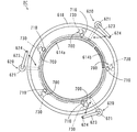
次に、裏面洗浄処理ユニットBCについて図面を用いて詳細に説明する。図5および図6は、裏面洗浄処理ユニットBCの構成を示す側面図および概略平面図である。なお、図6には、裏面洗浄処理ユニットBCの一部の構成要素が模式的に示される。
(3) Back surface cleaning unit Next, the back surface cleaning unit BC will be described in detail with reference to the drawings. 5 and 6 are a side view and a schematic plan view showing the configuration of the back surface cleaning processing unit BC. FIG. 6 schematically shows some components of the back surface cleaning unit BC.
なお、本実施の形態において、裏面洗浄処理ユニットBCは、図示しない筐体を備え、その筐体の内部に以下の構成要素が設けられる。 In the present embodiment, the back surface cleaning processing unit BC includes a housing (not shown), and the following components are provided inside the housing.
図5および図6に示すように、裏面洗浄処理ユニットBCは、基板Wを水平に保持して回転させるスピンチャック600を備える。スピンチャック600は、スピンモータ200、回転軸210、円板状のスピンプレート520、プレート支持部材510、円板状の遮断板525、マグネットプレート614a,614bおよび複数の基板保持機構700を含む。
As shown in FIGS. 5 and 6, the back surface cleaning processing unit BC includes a
裏面洗浄処理ユニットBCの上部にスピンモータ200が設けられている。スピンモータ200は、モータ支持部材200sによって支持されている。モータ支持部材200sは、鉛直方向に延びる貫通孔200hを有し、モータ固定部290に取り付けられている。モータ固定部290は、図示しない裏面洗浄処理ユニットBCの筐体に取り付けられている。
A
スピンモータ200の内部から下方に延びるように円筒形状を有する回転軸210が設けられている。回転軸210はスピンモータ200の出力軸として機能する。
A
回転軸210の下端部にはプレート支持部材510が取り付けられている。後述するように、プレート支持部材510は円筒形状を有する。プレート支持部材510によりスピンプレート520が水平に支持されている。プレート支持部材510およびスピンプレート520の下面に遮断板525が固定部材525a,525bにより水平に固定されている。遮断板525の中心部には、貫通孔525hが形成されている。スピンモータ200によって回転軸210が回転することにより、プレート支持部材510、スピンプレート520および遮断板525が鉛直軸の周りで一体的に回転する。
A
モータ支持部材200sの貫通孔200h、スピンモータ200の回転軸210の内部、およびプレート支持部材510の内部には、流体供給管400が挿通されている。流体供給管400を通して、スピンチャック600により保持される基板W上に気体を供給することができる。流体供給管400およびその周辺部材の構造の詳細は後述する。
A
スピンプレート520の周縁部には、複数(図6においては5つ)の基板保持機構700が回転軸210に関して等角度間隔で設けられている。基板保持機構700の個数は、5つ以上であることが望ましい。その理由については後述する。
A plurality (five in FIG. 6) of
各基板保持機構700は、主として保持ピン710、支持部720、軸部730およびマグネット790から構成される。スピンプレート520に支持部720が設けられている。支持部720の内部で軸部730が回転可能に支持されている。軸部730の下端部に、略円柱形状を有する保持ピン710が取り付けられている。軸部730の上端部にマグネット790が取り付けられている。
Each
各基板保持機構700は、保持ピン710が基板Wの外周端部に当接する閉状態と、保持ピン710が基板Wの外周端部から離間する開状態とに切替可能である。本例では、マグネット790のN極が内側にある場合に各基板保持機構700が閉状態となり、マグネット790のS極が内側にある場合に各基板保持機構700が開状態となる。基板保持機構700の構造の詳細については後述する。なお、図6では、基板保持機構700における保持ピン710と軸部730との位置関係を明確にするため、支持部720およびマグネット790の図示を省略している。
Each
図5に示すように、スピンプレート520の上方には、回転軸210を中心とする周方向に沿ってマグネットプレート614a,614bが配置される。マグネットプレート614a,614bは、外側にS極を有し、内側にN極を有する。マグネットプレート614a,614bは、マグネット昇降機構617a,617bによってそれぞれ独立に昇降し、基板保持機構700のマグネット790よりも高い上方位置と基板保持機構700のマグネット790とほぼ等しい高さの下方位置との間で移動する。
As shown in FIG. 5,
マグネットプレート614a,614bの昇降により、各基板保持機構700が開状態と閉状態とに切り替えられる。マグネットプレート614a,614bおよび基板保持機構700の動作の詳細については後述する。
Each
スピンチャック600の外方には、基板Wから飛散する洗浄液を受け止めるためのガード618が設けられている。ガード618は、スピンチャック600の回転軸210に関して回転対称な形状を有する。また、ガード618は、ガード昇降機構618aにより昇降する。ガード618により受け止められた洗浄液は、図示しない排液装置または回収装置により排液または回収される。
A
ガード618の外方には、3つ以上(本例では3つ)の基板受け渡し機構620がスピンチャック600の回転軸210を中心として等角度間隔で配置されている。各基板受け渡し機構620は、昇降回転駆動部621、回転軸622、アーム623および保持ピン624を含む。昇降回転駆動部621から上方に延びるように回転軸622が設けられ、回転軸622の上端部から水平方向に延びるようにアーム623が連結されている。アーム623の先端部に、基板Wの外周端部を保持するための保持ピン624が設けられている。
Outside the
昇降回転駆動部621により、回転軸622が昇降動作および回転動作を行う。それにより、保持ピン624が水平方向および鉛直方向に移動する。
The
また、裏面洗浄処理ユニットBCの下部には、略円柱形状の洗浄ブラシ630が配置されている。洗浄ブラシ630はモータ635の回転軸に取り付けられており、鉛直軸の周りで回転駆動される。モータ635はブラシ保持部材631により保持されている。ブラシ保持部材631は、ブラシ移動機構632によって駆動される。それにより、洗浄ブラシ630が水平方向および鉛直方向に移動する。
A substantially
洗浄ブラシ630の近傍におけるブラシ保持部材631の部分には洗浄ノズル633が取り付けられている。洗浄ノズル633には洗浄液が供給される液供給管(図示せず)が接続されている。洗浄ノズル633の吐出口は洗浄ブラシ630周辺に向けられており、吐出口から洗浄ブラシ630周辺に向けて洗浄液が吐出される。なお、本例では洗浄水として純水が用いられる。
A cleaning
(4)基板保持機構の詳細
基板保持機構700の詳細について説明する。図7は基板保持機構700の外観斜視図であり、図8は基板保持機構700の分解斜視図である。なお、図8ではマグネット790の図示を省略する。
(4) Details of Substrate Holding Mechanism Details of the
図7に示すように、基板保持機構700は、主として保持ピン710、支持部720、軸部730およびマグネット790から構成される。図8に示すように、支持部720は、回転規制部材720a、軸支持部材720bおよび2つのベアリング720cを含む。また、軸部730は、回転部材730a、連結部材730bおよびピン固定部材730cを含む。
As shown in FIG. 7, the
支持部720および軸部730を構成する複数の部材は、複数のねじN1〜N5(図8および後述する図17)により互いに接続され、図7に示すように、スピンプレート520の周縁部に取り付けられる。
A plurality of members constituting the
(4−1)支持部における各部材の接続関係
図9は、支持部720における各部材の接続関係を説明するための分解斜視図である。図9に示すように、回転規制部材720aは、ねじ受け部721および鍔部722からなる。ねじ受け部721の中心を通るように鉛直方向に延びる貫通孔721hが形成されている。貫通孔721hの内径は、後述する回転部材730aの径大部732(後述する図10)の外径よりもやや大きい。
(4-1) Connection Relationship of Each Member in Support Unit FIG. 9 is an exploded perspective view for explaining the connection relationship of each member in the
ねじ受け部721は外周壁721aを有する。ねじ受け部721の上端部は開放されている。外周壁721aの内側には貫通孔721hを取り囲むように、略扇形状を有する2つの上面721b,721cが形成されている。
The
ねじ受け部721の中心軸に関して所定の角度範囲に一方の上面721bが形成され、一方の上面721bを除く角度範囲に他方の上面721cが形成されている。鉛直方向において、一方の上面721bの位置は他方の上面721cの位置よりも高い。そのため、2つの上面721b,721c間には、鉛直方向に平行な2つの回転規制面721dが形成されている。
One
鍔部722は、ねじ受け部721の下端部のほぼ全周から所定長さ分外方へ突出するように形成されている。鍔部722には鉛直方向に延びる2つの貫通孔722aが形成されている。また、鍔部722には2つのくぼみ722bが形成されている。
The
軸支持部材720bは、第1筒状部724、鍔部725および第2筒状部726からなる。第1筒状部724および第2筒状部726の中心軸は互いに一致しており、第1筒状部724および第2筒状部726の内部空間は互いに連通している。
The
第1筒状部724には、円筒形状を有する2つのベアリング720cが鉛直方向に並んだ状態で挿入される。2つのベアリング720cの内径は、後述する回転部材730aの径大部732(後述する図10)の外径よりもやや小さい。
Two
第2筒状部726においては、円筒形状を有する外壁726aおよび内壁726bが二重に形成されている。これにより、外壁726aと内壁726bとの間に環状の空間が形成されている。
In the 2nd
軸支持部材720bの内部には環状の段差面726s(後述する図15)が形成される。2つのベアリング720cのうち下側のベアリング720cの下端部が、環状の段差面726s(後述する図15)により支持される。
An
スピンプレート520の周縁部においては、1つの基板保持機構700に対応して予め1つの貫通孔521および2つのねじ孔522が形成されている。第2筒状部726の外壁726aの外径は、スピンプレート520の貫通孔521の内径よりもやや小さい。
In the peripheral portion of the
軸支持部材720bの第2筒状部726がスピンプレート520の貫通孔521に嵌め込まれる。軸支持部材720bの2つの貫通孔725bがスピンプレート520の2つのねじ孔522上にそれぞれ位置するように軸支持部材720bが位置決めされる。2つのねじN4がそれぞれ2つの貫通孔725bを通して2つのねじ孔522に取り付けられることにより、軸支持部材720bがスピンプレート520上に固定される。
The second
軸支持部材720b上に回転規制部材720aが取り付けられる。回転規制部材720aの2つの貫通孔722aが軸支持部材720bの2つのねじ孔725a上にそれぞれ位置するように回転規制部材720aが位置決めされる。この場合、2つのねじN4の頭がそれぞれ回転規制部材720aの2つのくぼみ722b内に位置する。
A
2つのねじN3がそれぞれ2つの貫通孔722aを通して2つのねじ孔725aに取り付けられる。このようにして、回転規制部材720aと軸支持部材720bとが接続される。
Two screws N3 are respectively attached to the two
(4−2)軸部
図10は、図8の回転部材730aの詳細を説明するための図である。図10(a)に回転部材730aの上面図が示され、図10(b)に回転部材730aの一方側面図が示され、図10(c)に回転部材730aの下面図が示され、図10(d)に回転部材730aの他方側面図が示されている。
(4-2) Shaft Part FIG. 10 is a view for explaining details of the rotating
図10(a)〜図10(d)に示すように、回転部材730aは、円板部731、径大部732および径小部733からなる。円板部731は、上面および下面を有するとともに、所定の厚みを有する。円板部731の中央には貫通孔731hが形成されている。また、円板部731においては、貫通孔731hを取り囲むように1つのねじ孔731aおよび2つのねじ孔731bが形成されている。1つのねじ孔731aの内径は他の2つのねじ孔731bの内径よりも大きい。
As shown in FIGS. 10A to 10D, the rotating
径大部732および径小部733は中空軸構造を有する。径小部733の内径は一定であり、円板部731の貫通孔731hの内径よりも小さい。
The
径大部732において、鉛直方向の中心から円板部731までの部分の内径は円板部731の貫通孔731hの内径に等しく、鉛直方向の中心から径小部733までの部分の内径は径小部733の内径に等しい。これにより、径大部732の内部において、鉛直方向の中心には水平方向に平行な環状の段差面732cが形成されている(後述する図15)。
In the
径小部733の下端部近傍の外周面は、径小部733の中心軸に関して対称な位置に2つの平坦部733kを有する。2つの平坦部733kはそれぞれ径小部733の外周面の一部を切り欠くことにより形成されている。2つの平坦部733kは互いに平行である。
The outer peripheral surface in the vicinity of the lower end of the small-
図11は、図8の連結部材730bの詳細を説明するための図である。図11(a)に連結部材730bの上面図が示され、図11(b)に連結部材730bの側面図が示され、図11(c)に連結部材730bの下面図が示されている。
FIG. 11 is a diagram for explaining the details of the connecting
図11(a)〜図11(c)に示すように、連結部材730bは、略円板形状を有する連結本体部734を備える。連結本体部734の中央部には貫通孔734hが形成されている。連結本体部734は上面734aを有するとともに、第1、第2および第3の下面734b,734c,734dを有する。第1の下面734bの位置は第2の下面734cの位置よりも高く、第2の下面734cの位置は第3の下面734dの位置よりも高い。
As shown in FIGS. 11A to 11C, the connecting
連結本体部734の上面734a側には、筒状突出部735aおよび2つの軸連結突出部735bが設けられている。筒状突出部735aは、連結本体部734の上面734aから上方へ突出するように、連結本体部734の外周部全周に渡って形成されている。
On the
2つの軸連結突出部735bは、筒状突出部735aの内側で、貫通孔734hを挟んで連結本体部734の上面734aから上方へ突出するように形成されている。2つの軸連結突出部735bは互いに平行に対向する平面(以下、対向面と呼ぶ。)と円弧状の曲面とをそれぞれ有する。
The two
2つの軸連結突出部735bの2つの対向面間の距離は、図10の回転部材730aの2つの平坦部733k間の距離とほぼ等しい。これにより、基板保持機構700の組み立て時には、回転部材730aの先端部が2つの軸連結突出部735bの2つの対向面間に配置される。
The distance between the two opposing surfaces of the two
第1の下面734bの下方に第1の空間734pが形成されている。第1の下面734bの外形は、後述する図12のピン固定部材730cの固定部736の外形にほぼ等しい。基板保持機構700の組み立て時には、後述する図12の固定部736が第1の空間734p内に配置される。
A
第2の下面734cの下方に第2の空間734qが形成されている。第2の下面734bの外形の一部は、後述する図13の保持ピン710の円板部711の外形の一部とほぼ等しい。基板保持機構700の組み立て時には、後述する図13の円板部711の一部が第2の空間734q内に配置される。
A
図12は、図8のピン固定部材730cの詳細を説明するための図である。図12(a)にピン固定部材730cの上面図が示され、図12(b)にピン固定部材730cの一方側面図が示され、図12(c)にピン固定部材730cの下面図が示され、図12(d)にピン固定部材730cの他方側面図が示されている。
FIG. 12 is a diagram for explaining details of the
図12(a)〜図12(d)に示すように、ピン固定部材730cは、固定部736、中継部737および支持部738からなる。固定部736は円板形状を有する。固定部736の一方の半円部分にねじ孔736hが形成されている。固定部736の他方の半円部分の下面に中継部737が設けられている。中継部737は半円板形状を有する。中継部737の下面に支持部738が設けられている。
As shown in FIGS. 12A to 12D, the
支持部738は、支持本体部738xおよび2つのピン支持アーム738aからなる。支持本体部738xは一方向に延びる板形状を有する。支持本体部738xの両端部から屈曲するように2つのピン支持アーム738aが形成されている。2つのピン支持アーム738aは支持部738の両端部からそれぞれの先端部にかけて湾曲している。2つのピン支持アーム738aの先端部は互いに離間している。2つのピン支持アーム738aの間に図8の保持ピン710を配置するための空間738bが形成されている。
The
(4−3)保持ピン
図13は、図8の保持ピン710の詳細を説明するための図である。図13(a)に保持ピン710の上面図が示されている。図13(b)〜(e)には90°ずつ異なる方向D1〜D4から見た保持ピン710の側面図が示されている。図13(f)に図13(b)のE1−E1線断面図が示されている。
(4-3) Holding Pin FIG. 13 is a diagram for explaining the details of the holding
図13(a)〜(e)に示すように、この保持ピン710は円板部711およびピン本体部712からなる。ピン本体部712は略円柱形状を有する。ピン本体部712の上端部に円板部711が設けられている。円板部711の中心軸とピン本体部712の中心軸とは一致している。円板部711の外径はピン本体部712の外径よりも大きい。
As shown in FIGS. 13A to 13E, the holding
ピン本体部712の下端部近傍には基板当接部713が形成されている。基板当接部713の外径は、ピン本体部712における他の部分の外径に比べて小さい。複数の基板保持機構700により基板Wが保持される場合には、複数の保持ピン710の基板当接部713が基板Wの外周端部に当接する。
A
図13(c),(f)に示すように、方向D2から見た保持ピン710の側面には1つの平坦部714が形成されている。図13(d),(f)に示すように、方向D3から見た保持ピン710の側面には2つの平坦部714が形成されている。図13(e),(f)に示すように、方向D4から見た保持ピン710の側面には3つの平坦部714が形成されている。図13(b),(f)に示すように、方向D1から見た保持ピン710の側面には平坦部714は形成されていない。これらの平坦部714は、保持ピン710の周方向の位置を識別するために設けられる。
As shown in FIGS. 13C and 13F, one
(4−4)軸部における各部材の接続関係
図14は軸部730における各部材の接続関係を説明するための分解斜視図であり、図15は軸部730における各部材の接続関係を説明するための断面図である。
(4-4) Connection Relationship of Each Member in Shaft Part FIG. 14 is an exploded perspective view for explaining the connection relation of each member in the
図14および図15に示すように、回転部材730aの内部に図8のねじN1が挿通される。ねじN1の先端部は、回転部材730aの径小部733の先端部から所定の長さ分突出する。また、回転部材730aのねじ孔731a(図10)にねじN2が取り付けられる。ねじN2の先端部は、円板部731の下面から所定の長さ分突出する。
As shown in FIGS. 14 and 15, the screw N1 of FIG. 8 is inserted into the rotating
図15に示すように、ねじN2の先端部が回転規制部材720aの上面721c(図9)上に位置するように、回転部材730aが支持部720内に嵌め込まれる。支持部720内では、回転部材730aが図9の2つのベアリング720cにより保持される。この状態で、回転部材730aは、回転部材730aの中心軸に関して2つの回転規制面721d(図9および図14)の間の角度範囲内で周方向に回転可能である。回転部材730aの先端部(径小部733の先端部)は、軸支持部材720bの内部に位置する。
As shown in FIG. 15, the rotating
回転部材730aが支持部720内に嵌め込まれた状態で、軸支持部材720bおよび回転部材730aの先端部に下方から連結部材730bが取り付けられる。連結部材730bの筒状突出部735aは第2筒状部726の外壁726aと内壁726bとの間の環状の空間726c内に収容される。
In a state where the rotating
上述のように、回転部材730aの先端部が連結部材730bの2つの軸連結突出部735b間に配置される。このとき、回転部材730aの2つの平坦部733kは、連結部材730bの2つの軸連結突出部735bの2つの対向面にそれぞれ当接する(図14)。これにより、回転部材730aが回転する場合には、回転部材730aとともに連結部材730bも回転する。
As described above, the distal end portion of the rotating
ピン固定部材730cに保持ピン710が取り付けられる。具体的には、保持ピン710の円板部711がピン固定部材730cの固定部736とピン支持アーム738aとの間に位置するように、保持ピン710のピン本体部712がピン固定部材730cの空間738b(図12)内に配置される。
A holding
ピン固定部材730cの固定部736が連結部材730bの第1の空間734p内に配置され、保持ピン710の円板部711が連結部材730bの第2の空間734q内に配置される。第1の空間734p内に突出するねじN1の先端部が固定部736のねじ孔736hに取り付けられる。
The fixing
ねじN1が締め込まれることにより、図15に太い矢印で示すように、ピン固定部材730cが回転部材730aおよび連結部材730bに近づくように鉛直方向に移動する。その結果、保持ピン710の円板部711の上面が、連結部材730bの第2の下面734cに当接するとともに、第2の下面734cを上方に押圧する。これにより、保持ピン710が回転部材730aおよび連結部材730bに固定される。この状態で、回転部材730aおよび連結部材730bが回転する場合には、回転部材730aおよび連結部材730bとともに保持ピン710も回転する。
When the screw N1 is tightened, the
(4−5)マグネット
図16は、図7のマグネット790の取り付け状態を示す外観斜視図である。本実施の形態において、マグネット790は、ケーシング内に磁石が収容された構成を有する。マグネット790には、鉛直方向に延びる2つの貫通孔790hおよび鉛直方向に延びる溝790gが形成されている。
(4-5) Magnet FIG. 16 is an external perspective view showing a state where the
溝790gが回転部材730aの貫通孔731h上に位置しかつ2つの貫通孔790hが回転部材730aの2つのねじ孔731b上にそれぞれ位置するように、マグネット790が位置決めされる。この状態で、2つのねじN5がそれぞれ2つの貫通孔790hを通して2つのねじ孔731bに取り付けられる。これにより、マグネット790が回転部材730aに固定される。
The
この場合、マグネット790の溝790gがねじN1上に位置するので、作業者は、レンチまたはドライバー等の工具を用いて、基板保持機構700の上方からねじN1を容易に締め込むことができる。または、作業者は、基板保持機構700の上方からねじN1を容易に緩めることができる。
In this case, since the
(4−6)保持ピンにおける基板との当接部の変更
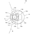
図17は基板保持機構700の下面図である。図17では、保持ピン710、連結部材730bおよびピン固定部材730cのみを図示する。図17に示すように、保持ピン710の中心軸710cが回転部材730a(図15)の中心軸700cの延長線上からずれるように、保持ピン710が連結部材730bに固定される。これにより、回転部材730a(図15)が回転することにより、図17の矢印17Aで示すように、保持ピン710が中心軸700cに沿う鉛直方向の軸の周りで回転する。このようにして、基板保持機構700が閉状態と開状態とに切替えられる。
(4-6) Change of Contact Portion of Holding Pin with Substrate FIG. 17 is a bottom view of the
この基板保持機構700においては、図17の矢印17Bで示すように、図15のねじN1を緩めることにより保持ピン710を周方向に回転させることができる。
In the
基板保持機構700が閉状態と開状態とに繰り返し切替えられると、保持ピン710における基板Wの外周端部との当接部cpが磨耗する。この場合、この場合、作業者は、図15のねじN1を緩め、保持ピン710を周方向に回転させた後、再び図15のねじN1を締め込む。これにより、作業者は、保持ピン710における基板Wの外周端部との当接部cpを、保持ピン710の一部分から他の部分に容易に変更することができる。
When the
このとき、作業者は、保持ピン710の外周面に形成された図13の複数の平坦部714を視認することにより、保持ピン710の磨耗部分を容易に認識することができるとともに、保持ピン710を周方向に90°ずつ正確に回転させることができる。
At this time, the operator can easily recognize the worn portion of the holding
また、作業者は、保持ピン710の基板当接部713のほぼ全周が磨耗した場合に、図15のねじN1を十分に緩めることにより、保持ピン710をピン固定部材730cから取り外し、新たな保持ピン710をピン固定部材730cに取り付けることができる。このように、保持ピン710の交換を容易に行うことができる。
Further, when the entire circumference of the
(5)流体供給管の詳細
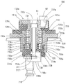
図5の流体供給管400およびその周辺部材の構造の詳細を図18および図19を参照しつつ説明する。図18は主として図5の流体供給管400の構造を示す縦断面図である。図19(a)は図5の流体供給管400の先端部近傍の構造を示す拡大縦断面図であり、図19(b)は図19(a)の矢印YAから見た流体供給管400の先端部の平面図である。
(5) Details of Fluid Supply Pipe Details of the structure of the
上述のように、流体供給管400は、モータ支持部材200s、スピンモータ200、回転軸210およびプレート支持部材510に挿通されている。
As described above, the
図18に示すように、流体供給管400は、モータ支持部材200sの上方で湾曲し、水平方向に延びている。以下の説明において、鉛直方向に延びる直管部の端部を先端部と呼び、水平方向に延びる直管部の端部を後端部と呼ぶ。
As shown in FIG. 18, the
流体供給管400において、鉛直方向に延びる直管部の湾曲部近傍には、第1フランジFR1が一体形成されている。また、後端部には第2フランジFR2が一体形成されている。
In the
第1フランジFR1がモータ支持部材200sに固定され、第2フランジFR2が管固定部280に固定される。管固定部280は、図示しない裏面洗浄処理ユニットBCの筐体に取り付けられる。
The first flange FR1 is fixed to the
これにより、流体供給管400は、管固定部280、モータ支持部材200sおよびモータ固定部290により、裏面洗浄処理ユニットBCの筐体に固定される。
Thereby, the
上述のように、スピンモータ200は、モータ支持部材200sにより支持されている。これにより、流体供給管400がモータ支持部材200sに取り付けられることにより、スピンモータ200が動作する場合でも、流体供給管400とスピンモータ200との位置関係が保たれる。したがって、流体供給管400に位置ずれが発生することが防止される。
As described above, the
図19(a),(b)に示すように、流体供給管400は、ガイド管410の内部に気体供給管420が収容された構造を有する。気体供給管420は基板Wに気体(本例ではN2ガス)を供給するために用いられる。
As shown in FIGS. 19A and 19B, the
本実施の形態において、ガイド管410はステンレス鋼からなる。気体供給管420はPTFE(四フッ化エチレン樹脂)およびPFA(四フッ化エチレン・パーフルオロアルコキシエチレン共重合体)等のフッ素樹脂からなる。
In the present embodiment, guide
図19(a)に示すように、気体供給管420は、その先端部が遮断板525の貫通孔525hから僅かに下方に突出するように設けられる。これにより、遮断板525と基板Wとの間にN2ガスを確実に供給することができる。なお、気体供給管420の先端部を遮断板525に固定してもよい。
As shown in FIG. 19A, the
流体供給管400の先端部の周辺部材について説明する。本例では、回転軸210は約20mmの内径を有し、ガイド管410は約18mmの外径を有する。これにより、流体供給管400が図18のモータ支持部材200sおよび管固定部280に取り付けられた状態で、回転軸210とガイド管410との間に約1mmのギャップGAが形成される。
The peripheral members at the tip of the
流体供給管400の先端部近傍において、回転軸210には、略円筒形状を有するプレート支持部材510が取り付けられている。プレート支持部材510の内周面510hは、中心軸に沿って階段状に形成されている。
A
プレート支持部材510を回転軸210に取り付ける際には、プレート支持部材510の内周面510hと回転軸210の外周面との間の隙間に円筒形状のパッド固定片512を嵌め込み、パッド固定片512をプレート支持部材510のねじ受け部511にネジ止めする。これにより、プレート支持部材510が回転軸210の先端部に確実に固定される。
When the
プレート支持部材510の下端部近傍には、フランジ510Fが形成されている。フランジ510Fとスピンプレート520とがネジ止めされることにより、スピンプレート520が回転軸210に固定される。
A
図18に示すように、流体供給管400の後端部には、上述のように第2フランジFR2が形成されている。そして、第2フランジFR2は管固定部280に固定される。また、流体供給管400の後端部近傍には、供給管固定部490が設けられる。供給管固定部490において、気体供給管420がガイド管410に固定される。
As shown in FIG. 18, the second flange FR2 is formed at the rear end of the
気体供給管420は、ガイド管410の後端部から外部に延びている。ガイド管410の後端部から延びる気体供給管420の後端部は、図示しない気体供給装置に接続される。気体供給装置から気体供給管420にN2ガスが供給されることにより、基板WにN2ガスが供給される。
The
(6)基板の保持動作
スピンチャック600による基板Wの保持動作について説明する。図20および図21は、スピンチャック600による基板Wの保持動作を説明するための図である。
(6) Substrate Holding Operation The substrate W holding operation by the
まず、図20(a)に示すように、ガード618が基板保持機構700よりも低い位置に移動する。そして、複数の基板受け渡し機構620(図5)の保持ピン624がガード618の上方を通ってスピンプレート520の下方に移動する。複数の保持ピン624上に第4のセンターロボットCR4(図1)により基板Wが載置される。
First, as shown in FIG. 20A, the
このとき、マグネットプレート614a,614bは上方位置にある。この場合、マグネットプレート614a,614bの磁力線Bは、基板保持機構700のマグネット790の高さにおいて内側から外側に向かう。それにより、各基板保持機構700のマグネット790のS極が内側に吸引される。したがって、各基板保持機構700は開状態となる。
At this time, the
続いて、図20(b)に示すように、複数の保持ピン624が基板Wを保持した状態で上昇する。これにより、基板Wが複数の基板保持機構700の保持ピン710の間に移動する。
Subsequently, as shown in FIG. 20B, the plurality of holding
続いて、図21(a)に示すように、マグネットプレート614a,614bが下方位置に移動する。この場合、各基板保持機構700のマグネット790のN極が内側に吸引される。それにより、各基板保持機構700が閉状態となり、各基板保持機構700の保持ピン710によって基板Wの外周端部が保持される。なお、各基板保持機構700は、隣接する保持ピン624間で基板Wの外周端部を保持する。そのため、基板保持機構700と保持ピン624とは互いに干渉しない。その後、複数の保持ピン624がガード618の外方に移動する。
Subsequently, as shown in FIG. 21A, the
続いて、図21(b)に示すように、ガード618が基板保持機構700により保持される基板Wを取り囲む高さに移動する。そして、基板Wの裏面洗浄処理が行われる。
Subsequently, as shown in FIG. 21B, the
(7)裏面洗浄処理
図22および図23は、基板Wの裏面洗浄処理について説明するための側面図である。
(7) Backside Cleaning Processing FIGS. 22 and 23 are side views for explaining the backside cleaning processing of the substrate W. FIG.
図22に示すように、基板Wの裏面洗浄処理時には、スピンチャック600により基板Wが回転するとともに、気体供給管420を通して遮断板525と基板Wとの間にN2ガスが供給される。これにより、遮断板525と基板Wとの間で、基板Wの中心部上から外側に向かうN2ガスの気流が形成される。
As shown in FIG. 22, during the back surface cleaning process of the substrate W, the substrate W is rotated by the
その状態で、洗浄ブラシ630がモータ635によって回転しながら基板Wの裏面に接触する。そして、洗浄ブラシ630が基板Wの中心部下方と周縁部下方との間で移動し、基板Wの裏面の全域に接触する。基板Wと洗浄ブラシ630との接触部分には、洗浄ノズル633から純水が供給される。これにより、基板Wの裏面の全体が洗浄ブラシ630により洗浄され、基板Wの裏面に付着する汚染物が取り除かれる。
In this state, the cleaning
続いて、図23(a)に示すように、マグネットプレート614aが下方位置に配置され、マグネットプレート614bが上方位置に配置される。この場合、図23(a),(b)に示すように、マグネットプレート614aの外方領域R1(図23(b))においては各基板保持機構700が閉状態となり、マグネットプレート614bの外方領域R2(図23(b))においては各基板保持機構700が開状態となる。すなわち、各基板保持機構700の保持ピン710は、マグネットプレート614aの外方領域R1を通過する際に基板Wの外周端部に接触した状態で維持され、マグネットプレート614bの外方領域R2を通過する際に基板Wの外周端部から離間する。
Subsequently, as shown in FIG. 23A, the
したがって、マグネットプレート614bの外方領域R2において、基板Wの外周端部の下面側の部分を洗浄ブラシ630により洗浄することができる。
Therefore, in the outer region R2 of the
なお、本例では、5つの基板保持機構700のうちの少なくとも4つの基板保持機構700がマグネットプレート614aの外方領域R1に位置する。この場合、各基板保持機構700の保持ピン710がマグネットプレート614bの外方領域R2を通過する際に基板Wの外周端部から離間しても、少なくとも4つの基板保持機構700により基板Wが保持される。それにより、基板Wの安定性が確保される。
In this example, at least four of the five
裏面洗浄処理の終了後、マグネットプレート614a,615bが下方位置に配置され、全ての基板保持機構700により基板Wが保持される。その状態で、スピンチャック600により基板Wが高速で回転する。それにより、基板Wに付着する純水が振り切られ、基板Wが乾燥する。
After completion of the back surface cleaning process, the
(8)実施の形態の効果
上述のように、作業者は、ねじN1を緩めることにより、保持ピン710に形成された複数の平坦部714を視認しつつ、保持ピン710の磨耗部分を容易に認識することができる。また、作業者は、保持ピン710に形成された複数の平坦部714を視認しつつ、保持ピン710を周方向に90°ずつ回転させることができる。このように、保持ピン710における基板Wの外周端部との当接部を、保持ピン710の複数の部分に容易に変更することができる。
(8) Effects of Embodiment As described above, the operator can easily wear the worn portion of the holding
このように、上記の基板保持機構700においては、保持ピン710の4つの部分で基板Wの外周端部を保持することができる。したがって、保持ピン710の基板当接部713の一部分が基板Wの外周端部に当接することにより磨耗しても、基板当接部713の他の部分が磨耗していない場合には、保持ピン710を交換する必要がなくなる。これにより、保持ピン710が長寿命化し、保持部材の交換周期が長くなる。その結果、保持ピン710の交換作業に伴う基板処理装置の停止時間を十分に短くすることができるので、基板処理装置の稼働率を向上させることが可能となる。
Thus, in the
(9)変形例
(9−1)図24は、保持ピンの他の構成例を説明するための図である。図24(a)に保持ピン710Aの上面図が示されている。図24(b)〜(e)には90°ずつ異なる方向D1〜D4から見た保持ピン710Aの側面図が示されている。図24(f)に図24(b)のE2−E2線断面図が示されている。図24の保持ピン710Aが図13の保持ピン710と異なるのは以下の点である。
(9) Modification (9-1) FIG. 24 is a diagram for explaining another configuration example of the holding pin. FIG. 24A shows a top view of the holding
図24(a)に示すように、この保持ピン710Aにおいては、円板部711の上面に保持ピン710の中心軸に関して等角度(90°)間隔で4つのくぼみh1,h2,h3,h4が形成されている。
As shown in FIG. 24 (a), in this holding
図25は、図24の保持ピン710Aを用いた基板保持機構700の一部拡大断面図である。図25に示すように、図24の保持ピン710Aを用いる場合には、ピン固定部材730cのねじ孔736hに取り付けられるねじN1の先端部に突出部N1tが設けられる。
FIG. 25 is a partially enlarged cross-sectional view of the
図24の保持ピン710Aが、ねじN1によりピン固定部材730cとともに連結部材730bに固定される。この場合、ねじN1の突出部N1tが保持ピン710Aの4つのくぼみh1〜h4のうちのいずれか1つ(本例ではくぼみh4)に差し込まれるように、ねじN1がピン固定部材730cのねじ孔736hに締め込まれる。これにより、保持ピン710Aが連結部材730bに固定された状態で、保持ピン710Aが周方向に回転することが防止される。このようにして、保持ピン710Aが連結部材730bに確実に固定される。
The holding
(9−2)図26は、保持ピンのさらに他の構成例を説明するための図である。図26(a)に保持ピン710Bの上面図が示されている。図26(b)〜(e)には90°ずつ異なる方向D1〜D4から見た保持ピン710Bの側面図が示されている。図26(f)に図26(b)のE3−E3線断面図が示されている。図26の保持ピン710Bが図13の保持ピン710と異なるのは以下の点である。
(9-2) FIG. 26 is a diagram for explaining still another configuration example of the holding pin. A top view of the holding
図26(a)〜図26(f)に示すように、この保持ピン710Bにおいては、ピン本体部712の上端部分に鍔部711Sが形成されている。鍔部711Sは、正方形状の横断面を有し、4つの側面711fを有する。4つの側面711fのうち2つの側面711fは互いに対向する。4つの側面711fのうち他の2つの側面711fは互いに対向する。
As shown in FIG. 26A to FIG. 26F, in the holding
図27は、図26の保持ピン710Bを用いた基板保持機構700の下面図である。図27では、保持ピン710B、連結部材730bおよびピン固定部材730cのみを図示する。
FIG. 27 is a bottom view of the
図27に示すように、ピン固定部材730cにおいて、2つのピン支持アーム738aの先端部には、互いに対向する対向面738zが形成されている。2つの対向面738z間の距離は、図26の保持ピン710Bの4つの側面711fのうち互いに対向する2つの側面711f間の距離とほぼ等しい。
As shown in FIG. 27, in the
4つの側面711fのうち互いに対向する2つの側面711fが2つの対向面738zにそれぞれ当接するように、図26の保持ピン710Bが2つのピン支持アーム738aの先端部の間に配置される。この状態で、図15のねじN1が締め込まれる。
The holding
これにより、保持ピン710Bが連結部材730bに固定された状態で、保持ピン710Bが周方向に回転することが防止される。このようにして、保持ピン710Bが連結部材730bに確実に固定される。
This prevents the holding
(9−3)上記の保持ピン710には、必ずしも複数の平坦部714が形成されなくてもよい。作業者が保持ピン710の周方向の位置を識別することができるのであれば、保持ピン710に複数の突起が形成されてもよいし、保持ピン710に複数の印がマーキングされてもよい。
(9-3) A plurality of
(9−4)裏面洗浄処理ユニットBCにおいては、基板Wの裏面および外周端部が必ずしも洗浄ブラシ630で洗浄されなくてもよい。裏面洗浄処理ユニットBCにおいては、洗浄ブラシ630を基板Wの裏面に接触させず、洗浄ノズル633から基板Wの裏面の全域に純水等の洗浄液を供給することにより裏面洗浄処理が行われてもよい。
(9-4) In the back surface cleaning processing unit BC, the back surface and the outer peripheral edge of the substrate W do not necessarily have to be cleaned with the cleaning
また、基板Wの裏面および外周端部の洗浄は、液体および気体の混合流体を吐出する二流体ノズルを用いて行ってもよい。さらに、基板Wの裏面および外周端部の洗浄は、高周波振動子を内蔵する超音波ノズルを用いて行ってもよい。超音波ノズルを用いる場合、超音波振動状態となった洗浄液が基板Wの裏面および外周端部に供給される。 Moreover, you may perform the washing | cleaning of the back surface and outer peripheral edge part of the board | substrate W using the two-fluid nozzle which discharges the mixed fluid of a liquid and gas. Furthermore, the back surface and the outer peripheral edge of the substrate W may be cleaned using an ultrasonic nozzle that incorporates a high-frequency vibrator. When the ultrasonic nozzle is used, the cleaning liquid in an ultrasonic vibration state is supplied to the back surface and the outer peripheral end of the substrate W.
(9−5)裏面洗浄処理ユニットBCにおいては、スピンモータ200および回転軸210がスピンプレート520の上側に設けられている。保持ピン710がスピンプレート520の下側に位置するように、基板保持機構700がスピンプレート520の周縁部に設けられている。これにより、スピンチャック600により基板Wが保持された状態で、基板Wの下面が露出する。
(9-5) In the back surface cleaning processing unit BC, the
これに限らず、基板保持機構700は、基板Wの上面が露出するように基板Wを保持するスピンチャックに適用されてもよい。
However, the
例えば、スピンモータ200および回転軸210がスピンプレート520の下側に設けられたスピンチャックがある。このスピンチャックにおいて、保持ピン710がスピンプレート520の上側に位置するように、基板保持機構700がスピンプレート520の周縁部に設けられてもよい。この場合、スピンチャックにより基板Wが保持された状態で、基板Wの上面が露出する。これにより、基板Wの上方の位置から基板Wの上面に対して種々の処理(洗浄処理、塗布処理または現像処理等)を行うことができる。
For example, there is a spin chuck in which the
上記のスピンチャック600を塗布ユニットBARC,RESに適用した場合には、反射防止膜またはレジスト膜の塗布液が供給ノズル52,62からスピンチャック600に保持された基板Wの上面に供給される。
When the above-described
また、上記のスピンチャック600を現像処理ユニットDEVに適用した場合には、現像液が供給ノズル72からスピンチャック600に保持された基板Wの上面に供給される。
When the
(9−6)上記実施の形態では、流体供給管400のガイド管410がステンレス鋼により形成される旨を説明したが、ガイド管410を形成する材料としては、ステンレス鋼の他、鉄、銅、青銅、黄銅、アルミニウム、銀、または金等の強靭な金属材料を用いることができる。
(9-6) In the above embodiment, it has been described that the
また、気体供給管420がフッ素樹脂により形成される旨を説明したが、気体供給管420を形成する材料としては、フッ素樹脂の他PVC(ポリ塩化ビニル)、PPS(ポリフェニレンサルファイド)、PTFE(ポリテトラフルオロエチレン)またはPFA(テトラフルオロエチレン・パーフルオロアルキルビニルエーテル共重合体)等のフレキシブル性を有する樹脂材料を用いることもできる。
Further, the
(9−7)裏面洗浄処理ユニットBCにおいて、遮断板525を設けずに、スピンプレート520と基板Wと近接させてその間の空間にN2ガスを供給してもよい。
(9-7) In the back surface cleaning processing unit BC, the N 2 gas may be supplied to the space between the
(9−8)裏面洗浄処理ユニットBC、塗布ユニットBARC,RES、現像処理ユニットDEV、加熱ユニットHP、冷却ユニットCPおよび載置兼冷却ユニットP−CPの個数は、各処理ブロックの処理速度に合わせて適宜変更してもよい。 (9-8) The number of back surface cleaning processing unit BC, coating unit BARC, RES, development processing unit DEV, heating unit HP, cooling unit CP and mounting / cooling unit P-CP matches the processing speed of each processing block. May be changed as appropriate.
(9−9)また、上記実施の形態では、裏面洗浄処理ユニットBCがインターフェースブロック15内に配置されるが、裏面洗浄処理ユニットBCが図1に示す現像処理ブロック12内に配置されてもよい。あるいは、裏面洗浄処理ユニットBCを含む裏面洗浄処理ブロックを図1に示す現像処理ブロック12とインターフェースブロック15との間に設けてもよい。
(9-9) Further, in the above embodiment, the back surface cleaning processing unit BC is disposed in the
(10)請求項の各構成要素と実施の形態の各要素との対応
以下、請求項の各構成要素と実施の形態の各要素との対応の例について説明するが、本発明は下記の例に限定されない。
(10) Correspondence between each constituent element of claim and each element of the embodiment Hereinafter, an example of correspondence between each constituent element of the claim and each element of the embodiment will be described. It is not limited to.
上記実施の形態では、スピンチャック600が基板保持装置の例であり、スピンプレート520が支持部材の例であり、保持ピン710が保持部材の例であり、軸部730が可動部材の例である。
In the above embodiment, the
また、ねじN1が回転阻止部材の例であり、複数の平坦部714が複数の指標の例であり、図13の円板部711の上面が保持部材の端面の例であり、図11の第2の下面734cが可動部材の当接面の例である。
Further, the screw N1 is an example of a rotation preventing member, the plurality of
さらに、図24のくぼみh1〜h4が複数の係止部の例であり、図25の突出部N1tが被係止部の例であり、図26の4つの側面711fが複数の制止面の例であり、図26の対向面738zが被制止面の例である。
Further, the recesses h1 to h4 in FIG. 24 are examples of a plurality of locking portions, the protrusion N1t in FIG. 25 is an example of a locked portion, and the four
また、スピンモータ200が回転駆動部の例であり、裏面洗浄処理ユニットBCが基板洗浄装置および基板処理装置の例であり、マグネットプレート614a,614bが駆動機構の例であり、洗浄ノズル633および洗浄ブラシ630が洗浄手段の例であり、洗浄ノズル633、洗浄ブラシ630および供給ノズル52,62,72が処理手段の例である。
Further, the
請求項の各構成要素として、請求項に記載されている構成または機能を有する他の種々の要素を用いることもできる。 As each constituent element in the claims, various other elements having configurations or functions described in the claims can be used.
本発明は、種々の基板の処理に有効に利用することができる。 The present invention can be effectively used for processing various substrates.
9 インデクサブロック
10 反射防止膜用処理ブロック
11 レジスト膜用処理ブロック
12 現像処理ブロック
15 インターフェースブロック
16 露光装置
16a 基板搬入部
16b 基板搬出部
17,18,19 隔壁
17A,17B,YA 矢印
30 メインコントローラ(制御部)
40 キャリア載置台
50 反射防止膜用塗布処理部
51,61,71,98,600 スピンチャック
52,72 供給ノズル
60 レジスト膜用塗布処理部
70 現像処理部
99 光照射器
100,101 反射防止膜用熱処理部
110,111 レジスト膜用熱処理部
120 現像用熱処理部
121 露光後ベーク用熱処理部
200 スピンモータ
200s モータ支持部材
200h,521,525h,721h,722a,725b,731h,734h,790h 貫通孔
210,622 回転軸
280 管固定部
290 モータ固定部
400 流体供給管
410 ガイド管
420 気体供給管
490 供給管固定部
500 基板処理装置
510 プレート支持部材
510F,FR1,FR2 フランジ
510h 内周面
511,721 ねじ受け部
512 パッド固定片
520 スピンプレート
522,731a,731b,736h ねじ孔
525 遮断板
525a,525b 固定部材
614a,614b マグネットプレート
617a,617b マグネット昇降機構
618 ガード
618a ガード昇降機構
620 基板受け渡し機構
621 昇降回転駆動部
623 アーム
624,710,710A,710B 保持ピン
630 洗浄ブラシ
631 ブラシ保持部材
632 ブラシ移動機構
633 洗浄ノズル
635 モータ
700 基板保持機構
700c,710c 中心軸
711,731 円板部
711f 側面
711S,722,725 鍔部
712 ピン本体部
713 基板当接部
714,733k 平坦部
720 支持部
720a 回転規制部材
720b 軸支持部材
720c ベアリング
721a 外周壁
721b,721c,734a 上面
721d 回転規制面
722b,h1,h2,h3,h4 くぼみ
724 第1筒状部
726 第2筒状部
726a 外壁
726b 内壁
726c,738b 空間
726s 段差面
730 軸部
730a 回転部材
730b 連結部材
730c ピン固定部材
732 径大部
732c 段差面
733 径小部
734 連結本体部
734b 第1の下面
734c 第2の下面
734d 第3の下面
734p 第1の空間
734q 第2の空間
735a 筒状突出部
735b 軸連結突出部
736 固定部
737 中継部
738 支持部
738a ピン支持アーム
738x 支持本体部
738z 対向面
790 マグネット
790g 溝
BARC,RES 塗布ユニット
BC 裏面洗浄処理ユニット
C キャリア
CP 冷却ユニット
cp 当接部
CR1〜CR4 第1〜第4のセンターロボット
CRH1〜CRH8 ハンド
D1〜D4 方向
DEV 現像処理ユニット
EEW エッジ露光部
H1 ハンド
HP 加熱ユニット
IFR インターフェース用搬送機構
IR インデクサロボット
IRH ハンド
LC ローカルコントローラ
N1〜N5 ねじ
N1t 突出部
R1,R2 外方領域
RBF 戻りバッファ部
SBF 送りバッファ部
PASS1〜PASS9 基板載置部
P−CP 載置兼冷却ユニット
W 基板
DESCRIPTION OF
40 Carrier mounting table 50 Antireflection film coating processing unit 51, 61, 71, 98, 600 Spin chuck 52, 72 Supply nozzle 60 Resist film coating processing unit 70 Development processing unit 99 Light irradiator 100, 101 For antireflection film Heat treatment section 110, 111 Heat treatment section for resist film 120 Heat treatment section for development 121 Heat treatment section for post-exposure baking 200 Spin motor 200s Motor support member 200h, 521, 525h, 721h, 722a, 725b, 731h, 734h, 790h Through hole 210, 622 Rotating shaft 280 Pipe fixing part 290 Motor fixing part 400 Fluid supply pipe 410 Guide pipe 420 Gas supply pipe 490 Supply pipe fixing part 500 Substrate processing apparatus 510 Plate support member 510F, FR1, FR2 Flange 510h Inner peripheral surface 511, 721 Screw receiver 512 Pad fixing piece 520 Spin plate 522, 731a, 731b, 736h Screw hole 525 Blocking plate 525a, 525b Fixing member 614a, 614b Magnet plate 617a, 617b Magnet lifting mechanism 618 Guard 618a Guard lifting mechanism 620 Substrate transfer mechanism 621 623 Arm 624, 710, 710A, 710B Holding pin 630 Cleaning brush 631 Brush holding member 632 Brush moving mechanism 633 Cleaning nozzle 635 Motor 700 Substrate holding mechanism 700c, 710c Central shaft 711, 731 Disc portion 711f Side surface 711S, 722, 725 712 Pin body 713 Substrate contact part 714, 733k Flat part 720 Support part 720a Rotation restricting member 720b Shaft support member 720c Bearer 721a outer peripheral wall 721b, 721c, 734a upper surface 721d rotation restricting surface 722b, h1, h2, h3, h4 hollow 724 first cylindrical portion 726 second cylindrical portion 726a outer wall 726b inner wall 726c, 738b space 726s stepped portion 730 shaft portion 730a Rotating member 730b Connecting member 730c Pin fixing member 732 Large diameter portion 732c Stepped surface 733 Small diameter portion 734 Connection main body portion 734b First lower surface 734c Second lower surface 734d Third lower surface 734p First space 734q Second space 735a Tubular protrusion 735b Shaft coupling protrusion 736 Fixed part 737 Relay part 738 Support part 738a Pin support arm 738x Support body part 738z Opposing surface 790 Magnet 790g Groove BARC, RES Coating unit BC Back surface cleaning unit C Carrier CP cooling unit cp contact part CR1 to CR4 first to fourth central robots CRH1 to CRH8 hand D1 to D4 direction DEV development processing unit EEW edge exposure part H1 hand HP heating unit IFR interface transport mechanism IR indexer robot IRH hand LC Local controller N1 to N5 Screw N1t Protruding part R1, R2 Outer area RBF Return buffer part SBF Feeding buffer part PASS1 to PASS9 Substrate placement part P-CP Placement and cooling unit W Substrate
Claims (9)
支持部材と、
基板の外周端部に当接可能な外周面を有する保持部材と、
前記保持部材を基板の主面に垂直な軸の周りで回転可能に保持するとともに、前記保持部材の外周面が基板の外周端部に当接する保持状態と前記保持部材の外周面が基板の外周端部から離間する解放状態とに移行可能に前記支持部材に設けられる可動部材と、
前記可動部材を前記保持状態と前記解放状態とに移行させる駆動機構と、
前記可動部材に対する前記保持部材の回転を阻止する固定状態と可動部材に対する前記保持部材の回転を許容する回転可能状態とに切り替え可能な回転阻止部材とを備え、
前記保持部材の外周面には、周方向に並ぶように互いに異なる複数の指標が設けられることを特徴とする基板保持装置。 A substrate holding device for holding a substrate,
A support member;
A holding member having an outer peripheral surface capable of contacting the outer peripheral end of the substrate;
The holding member is rotatably held around an axis perpendicular to the main surface of the substrate, the holding state in which the outer peripheral surface of the holding member is in contact with the outer peripheral end of the substrate, and the outer peripheral surface of the holding member is the outer periphery of the substrate A movable member provided on the support member so as to be able to shift to a released state separated from the end portion;
A drive mechanism for moving the movable member between the holding state and the released state;
A rotation preventing member that can be switched between a fixed state that prevents rotation of the holding member relative to the movable member and a rotatable state that allows rotation of the holding member relative to the movable member ;
A plurality of different indicators are provided on the outer peripheral surface of the holding member so as to be arranged in the circumferential direction .
前記可動部材は、前記保持部材の端面に当接する当接面を有し、
前記回転阻止部材は、前記保持部材の前記端面を前記可動部材の前記当接面に押圧することにより前記保持部材を固定状態にし、前記保持部材の前記端面を前記可動部材の前記当接面に押圧しないことにより前記保持部材を回転可能状態にすることを特徴とする請求項1または2記載の基板保持装置。 The holding member has an end surface orthogonal to the outer peripheral surface,
The movable member has a contact surface that contacts the end surface of the holding member;
The rotation preventing member presses the end surface of the holding member against the contact surface of the movable member to fix the holding member, and the end surface of the holding member is brought into contact with the contact surface of the movable member. 3. The substrate holding apparatus according to claim 1, wherein the holding member is brought into a rotatable state by not being pressed.
前記回転阻止部材には、前記固定状態で前記係止部に係止される被係止部が設けられることを特徴とする請求項3記載の基板保持装置。 A plurality of locking portions are provided on the end surface of the holding member along a circumference centered on the rotation center of the holding member,
The substrate holding device according to claim 3, wherein the rotation preventing member is provided with a locked portion that is locked to the locking portion in the fixed state.
前記可動部材には、前記保持部材の固定状態で前記制止面に接触する被制止面が設けられることを特徴とする請求項1〜4のいずれかに記載の基板保持装置。 The holding member is provided with a plurality of stop surfaces symmetrically with respect to the rotation center of the holding member,
Wherein the movable member, the substrate holding apparatus according to any one of claims 1 to 4, characterized in that the stop surface in contact with the stop surface in a fixed state of the holding member is provided.
前記回転駆動部は、前記支持部材の上側に設けられ、
前記保持部材は、前記支持部材の下側で前記可動部材により保持されることを特徴とする請求項6記載の基板保持装置。 The support member is disposed such that the rotation shaft extends in a vertical direction,
The rotational drive unit is provided on the upper side of the support member,
The substrate holding apparatus according to claim 6 , wherein the holding member is held by the movable member below the support member.
前記基板保持装置により回転される基板に洗浄処理を行う洗浄手段とを備えたことを特徴とする基板洗浄装置。 A substrate holding device according to claim 6 or 7, which holds a substrate;
A substrate cleaning apparatus, comprising: a cleaning unit that performs a cleaning process on the substrate rotated by the substrate holding device.
前記基板保持装置により回転される基板に所定の処理を行う処理手段とを備えたことを特徴とする基板処理装置。 A substrate holding device according to claim 6 or 7, which holds a substrate;
A substrate processing apparatus comprising: processing means for performing a predetermined process on the substrate rotated by the substrate holding device.
Priority Applications (1)
| Application Number | Priority Date | Filing Date | Title |
|---|---|---|---|
| JP2011070120A JP5686647B2 (en) | 2011-03-28 | 2011-03-28 | Substrate holding device, substrate cleaning device, and substrate processing apparatus |
Applications Claiming Priority (1)
| Application Number | Priority Date | Filing Date | Title |
|---|---|---|---|
| JP2011070120A JP5686647B2 (en) | 2011-03-28 | 2011-03-28 | Substrate holding device, substrate cleaning device, and substrate processing apparatus |
Publications (3)
| Publication Number | Publication Date |
|---|---|
| JP2012204759A JP2012204759A (en) | 2012-10-22 |
| JP2012204759A5 JP2012204759A5 (en) | 2014-01-16 |
| JP5686647B2 true JP5686647B2 (en) | 2015-03-18 |
Family
ID=47185355
Family Applications (1)
| Application Number | Title | Priority Date | Filing Date |
|---|---|---|---|
| JP2011070120A Active JP5686647B2 (en) | 2011-03-28 | 2011-03-28 | Substrate holding device, substrate cleaning device, and substrate processing apparatus |
Country Status (1)
| Country | Link |
|---|---|
| JP (1) | JP5686647B2 (en) |
Families Citing this family (4)
| Publication number | Priority date | Publication date | Assignee | Title |
|---|---|---|---|---|
| JP2014130883A (en) * | 2012-12-28 | 2014-07-10 | Ebara Corp | Substrate cleaning apparatus and substrate cleaning method |
| JP6836432B2 (en) * | 2017-03-22 | 2021-03-03 | 株式会社荏原製作所 | Substrate processing equipment and substrate processing method |
| JP7172163B2 (en) | 2018-06-20 | 2022-11-16 | 日新電機株式会社 | Substrate holder |
| JP6811287B2 (en) * | 2019-06-25 | 2021-01-13 | 株式会社Screenホールディングス | Board processing equipment |
Family Cites Families (3)
| Publication number | Priority date | Publication date | Assignee | Title |
|---|---|---|---|---|
| TWI366222B (en) * | 2004-11-23 | 2012-06-11 | Lam Res Ag | Apparatus and method for wet treatment of wafers |
| JP2008147423A (en) * | 2006-12-11 | 2008-06-26 | Seiko Epson Corp | Holding pin and holding device |
| JP5430873B2 (en) * | 2008-04-16 | 2014-03-05 | 株式会社Sokudo | Substrate cleaning apparatus and substrate processing apparatus having the same |
-
2011
- 2011-03-28 JP JP2011070120A patent/JP5686647B2/en active Active
Also Published As
| Publication number | Publication date |
|---|---|
| JP2012204759A (en) | 2012-10-22 |
Similar Documents
| Publication | Publication Date | Title |
|---|---|---|
| JP4832201B2 (en) | Substrate processing equipment | |
| JP5008280B2 (en) | Substrate processing apparatus and substrate processing method | |
| JP5154008B2 (en) | Substrate processing apparatus and substrate processing method | |
| JP4926433B2 (en) | Substrate processing apparatus and substrate processing method | |
| KR100875788B1 (en) | Substrate Processing Equipment | |
| JP6001896B2 (en) | Substrate cleaning apparatus and substrate processing apparatus having the same | |
| JP2006310724A (en) | Substrate processing equipment and method | |
| JP4794232B2 (en) | Substrate processing equipment | |
| JP5149513B2 (en) | Substrate processing equipment | |
| JP2009032889A (en) | Substrate cleaning apparatus and substrate processing system equipped with the same | |
| JP2009071026A (en) | Substrate processing apparatus and substrate processing method | |
| JP2006190921A (en) | Device and method for treating substrate | |
| JP2007201214A (en) | Substrate-treating device | |
| JP2009123800A (en) | Substrate processing apparatus | |
| JP5686647B2 (en) | Substrate holding device, substrate cleaning device, and substrate processing apparatus | |
| JP2007189138A (en) | Substrate-treating device | |
| JP6061484B2 (en) | Substrate cleaning apparatus and substrate processing apparatus having the same | |
| JP2009071028A (en) | Substrate processing apparatus and substrate processing method | |
| KR101178973B1 (en) | Substrate cleaning apparatus and substrate processing apparatus | |
| JP5269956B2 (en) | Substrate processing equipment | |
| JP2007201078A (en) | Substrate processing apparatus | |
| JP5091687B2 (en) | Substrate processing equipment | |
| JP2008198880A (en) | Substrate processing apparatus | |
| KR101068754B1 (en) | Substrate cleaning apparatus and substrate processing apparatus | |
| JP2007189139A (en) | Substrate-treating device |
Legal Events
| Date | Code | Title | Description |
|---|---|---|---|
| A521 | Request for written amendment filed |
Free format text: JAPANESE INTERMEDIATE CODE: A523 Effective date: 20131122 |
|
| A621 | Written request for application examination |
Free format text: JAPANESE INTERMEDIATE CODE: A621 Effective date: 20131122 |
|
| A977 | Report on retrieval |
Free format text: JAPANESE INTERMEDIATE CODE: A971007 Effective date: 20140911 |
|
| A131 | Notification of reasons for refusal |
Free format text: JAPANESE INTERMEDIATE CODE: A131 Effective date: 20140930 |
|
| A521 | Request for written amendment filed |
Free format text: JAPANESE INTERMEDIATE CODE: A523 Effective date: 20141112 |
|
| TRDD | Decision of grant or rejection written | ||
| A01 | Written decision to grant a patent or to grant a registration (utility model) |
Free format text: JAPANESE INTERMEDIATE CODE: A01 Effective date: 20150106 |
|
| A61 | First payment of annual fees (during grant procedure) |
Free format text: JAPANESE INTERMEDIATE CODE: A61 Effective date: 20150120 |
|
| R150 | Certificate of patent or registration of utility model |
Ref document number: 5686647 Country of ref document: JP Free format text: JAPANESE INTERMEDIATE CODE: R150 |
|
| R250 | Receipt of annual fees |
Free format text: JAPANESE INTERMEDIATE CODE: R250 |
|
| S111 | Request for change of ownership or part of ownership |
Free format text: JAPANESE INTERMEDIATE CODE: R313115 |
|
| R350 | Written notification of registration of transfer |
Free format text: JAPANESE INTERMEDIATE CODE: R350 |
|
| R250 | Receipt of annual fees |
Free format text: JAPANESE INTERMEDIATE CODE: R250 |
|
| R250 | Receipt of annual fees |
Free format text: JAPANESE INTERMEDIATE CODE: R250 |
|
| R250 | Receipt of annual fees |
Free format text: JAPANESE INTERMEDIATE CODE: R250 |
|
| R250 | Receipt of annual fees |
Free format text: JAPANESE INTERMEDIATE CODE: R250 |
|
| R250 | Receipt of annual fees |
Free format text: JAPANESE INTERMEDIATE CODE: R250 |
|
| S111 | Request for change of ownership or part of ownership |
Free format text: JAPANESE INTERMEDIATE CODE: R313117 |
|
| R350 | Written notification of registration of transfer |
Free format text: JAPANESE INTERMEDIATE CODE: R350 |
|
| R250 | Receipt of annual fees |
Free format text: JAPANESE INTERMEDIATE CODE: R250 |