JP5660710B2 - Target manufacturing method, magnetic recording medium manufacturing method - Google Patents
Target manufacturing method, magnetic recording medium manufacturing method Download PDFInfo
- Publication number
- JP5660710B2 JP5660710B2 JP2010174208A JP2010174208A JP5660710B2 JP 5660710 B2 JP5660710 B2 JP 5660710B2 JP 2010174208 A JP2010174208 A JP 2010174208A JP 2010174208 A JP2010174208 A JP 2010174208A JP 5660710 B2 JP5660710 B2 JP 5660710B2
- Authority
- JP
- Japan
- Prior art keywords
- mol
- magnetic
- target
- layer
- oxide
- Prior art date
- Legal status (The legal status is an assumption and is not a legal conclusion. Google has not performed a legal analysis and makes no representation as to the accuracy of the status listed.)
- Active
Links
- 238000004519 manufacturing process Methods 0.000 title claims description 17
- 238000002844 melting Methods 0.000 claims description 36
- 230000008018 melting Effects 0.000 claims description 31
- 229910004298 SiO 2 Inorganic materials 0.000 claims description 30
- 239000000758 substrate Substances 0.000 claims description 24
- 238000004544 sputter deposition Methods 0.000 claims description 23
- 238000000034 method Methods 0.000 claims description 22
- 239000000843 powder Substances 0.000 claims description 20
- 229910052804 chromium Inorganic materials 0.000 claims description 16
- 239000011521 glass Substances 0.000 claims description 15
- 238000005245 sintering Methods 0.000 claims description 14
- 229910000599 Cr alloy Inorganic materials 0.000 claims description 12
- 229910010413 TiO 2 Inorganic materials 0.000 claims description 11
- 229910052810 boron oxide Inorganic materials 0.000 claims description 10
- JKWMSGQKBLHBQQ-UHFFFAOYSA-N diboron trioxide Chemical compound O=BOB=O JKWMSGQKBLHBQQ-UHFFFAOYSA-N 0.000 claims description 10
- 229910052697 platinum Inorganic materials 0.000 claims description 10
- 229910018072 Al 2 O 3 Inorganic materials 0.000 claims description 9
- OGIDPMRJRNCKJF-UHFFFAOYSA-N titanium oxide Inorganic materials [Ti]=O OGIDPMRJRNCKJF-UHFFFAOYSA-N 0.000 claims description 7
- GEIAQOFPUVMAGM-UHFFFAOYSA-N ZrO Inorganic materials [Zr]=O GEIAQOFPUVMAGM-UHFFFAOYSA-N 0.000 claims description 6
- XHCLAFWTIXFWPH-UHFFFAOYSA-N [O-2].[O-2].[O-2].[O-2].[O-2].[V+5].[V+5] Chemical compound [O-2].[O-2].[O-2].[O-2].[O-2].[V+5].[V+5] XHCLAFWTIXFWPH-UHFFFAOYSA-N 0.000 claims description 5
- 229910000476 molybdenum oxide Inorganic materials 0.000 claims description 5
- PQQKPALAQIIWST-UHFFFAOYSA-N oxomolybdenum Chemical compound [Mo]=O PQQKPALAQIIWST-UHFFFAOYSA-N 0.000 claims description 5
- 229910052714 tellurium Inorganic materials 0.000 claims description 5
- PORWMNRCUJJQNO-UHFFFAOYSA-N tellurium atom Chemical compound [Te] PORWMNRCUJJQNO-UHFFFAOYSA-N 0.000 claims description 5
- 229910001935 vanadium oxide Inorganic materials 0.000 claims description 5
- 238000002156 mixing Methods 0.000 claims description 2
- 239000010410 layer Substances 0.000 description 178
- 239000006249 magnetic particle Substances 0.000 description 70
- 229910045601 alloy Inorganic materials 0.000 description 17
- 239000000956 alloy Substances 0.000 description 17
- 239000013078 crystal Substances 0.000 description 15
- 239000002245 particle Substances 0.000 description 14
- 239000000203 mixture Substances 0.000 description 10
- 239000011241 protective layer Substances 0.000 description 10
- 239000000463 material Substances 0.000 description 9
- 238000006243 chemical reaction Methods 0.000 description 8
- 229910052751 metal Inorganic materials 0.000 description 7
- 239000002184 metal Substances 0.000 description 7
- 230000000694 effects Effects 0.000 description 6
- 239000007789 gas Substances 0.000 description 5
- 230000001050 lubricating effect Effects 0.000 description 5
- 239000000696 magnetic material Substances 0.000 description 5
- 230000005415 magnetization Effects 0.000 description 5
- 230000008569 process Effects 0.000 description 5
- 238000002474 experimental method Methods 0.000 description 4
- 238000012545 processing Methods 0.000 description 4
- 229910052715 tantalum Inorganic materials 0.000 description 4
- 239000012298 atmosphere Substances 0.000 description 3
- 229910052796 boron Inorganic materials 0.000 description 3
- 238000005229 chemical vapour deposition Methods 0.000 description 3
- IVMYJDGYRUAWML-UHFFFAOYSA-N cobalt(II) oxide Inorganic materials [Co]=O IVMYJDGYRUAWML-UHFFFAOYSA-N 0.000 description 3
- 230000000052 comparative effect Effects 0.000 description 3
- 238000011156 evaluation Methods 0.000 description 3
- 238000010304 firing Methods 0.000 description 3
- 238000009689 gas atomisation Methods 0.000 description 3
- 238000007731 hot pressing Methods 0.000 description 3
- 230000001771 impaired effect Effects 0.000 description 3
- 239000011261 inert gas Substances 0.000 description 3
- 230000003993 interaction Effects 0.000 description 3
- 229910052755 nonmetal Inorganic materials 0.000 description 3
- 230000006911 nucleation Effects 0.000 description 3
- 238000010899 nucleation Methods 0.000 description 3
- 239000011148 porous material Substances 0.000 description 3
- 238000000926 separation method Methods 0.000 description 3
- 229910052710 silicon Inorganic materials 0.000 description 3
- XKRFYHLGVUSROY-UHFFFAOYSA-N Argon Chemical compound [Ar] XKRFYHLGVUSROY-UHFFFAOYSA-N 0.000 description 2
- 229910000531 Co alloy Inorganic materials 0.000 description 2
- 229910015372 FeAl Inorganic materials 0.000 description 2
- 229910002546 FeCo Inorganic materials 0.000 description 2
- 229910002555 FeNi Inorganic materials 0.000 description 2
- 229910000604 Ferrochrome Inorganic materials 0.000 description 2
- 229910052782 aluminium Inorganic materials 0.000 description 2
- 239000012300 argon atmosphere Substances 0.000 description 2
- 230000015572 biosynthetic process Effects 0.000 description 2
- 239000000919 ceramic Substances 0.000 description 2
- 230000008859 change Effects 0.000 description 2
- 238000007598 dipping method Methods 0.000 description 2
- 239000000428 dust Substances 0.000 description 2
- 238000005461 lubrication Methods 0.000 description 2
- 230000005389 magnetism Effects 0.000 description 2
- 238000000465 moulding Methods 0.000 description 2
- 229910052758 niobium Inorganic materials 0.000 description 2
- 229910052760 oxygen Inorganic materials 0.000 description 2
- 239000010702 perfluoropolyether Substances 0.000 description 2
- 239000002994 raw material Substances 0.000 description 2
- 229910052719 titanium Inorganic materials 0.000 description 2
- 229910052721 tungsten Inorganic materials 0.000 description 2
- 229910000838 Al alloy Inorganic materials 0.000 description 1
- IJGRMHOSHXDMSA-UHFFFAOYSA-N Atomic nitrogen Chemical compound N#N IJGRMHOSHXDMSA-UHFFFAOYSA-N 0.000 description 1
- OKTJSMMVPCPJKN-UHFFFAOYSA-N Carbon Chemical compound [C] OKTJSMMVPCPJKN-UHFFFAOYSA-N 0.000 description 1
- 229910052684 Cerium Inorganic materials 0.000 description 1
- 229910019222 CoCrPt Inorganic materials 0.000 description 1
- 229910003321 CoFe Inorganic materials 0.000 description 1
- 229910000684 Cobalt-chrome Inorganic materials 0.000 description 1
- 229910005347 FeSi Inorganic materials 0.000 description 1
- 229910005435 FeTaN Inorganic materials 0.000 description 1
- WHXSMMKQMYFTQS-UHFFFAOYSA-N Lithium Chemical compound [Li] WHXSMMKQMYFTQS-UHFFFAOYSA-N 0.000 description 1
- 229910052779 Neodymium Inorganic materials 0.000 description 1
- 229910052772 Samarium Inorganic materials 0.000 description 1
- 229910052581 Si3N4 Inorganic materials 0.000 description 1
- XUIMIQQOPSSXEZ-UHFFFAOYSA-N Silicon Chemical compound [Si] XUIMIQQOPSSXEZ-UHFFFAOYSA-N 0.000 description 1
- 229910008449 SnF 2 Inorganic materials 0.000 description 1
- 229910052771 Terbium Inorganic materials 0.000 description 1
- 230000002159 abnormal effect Effects 0.000 description 1
- 230000009471 action Effects 0.000 description 1
- 150000001298 alcohols Chemical class 0.000 description 1
- XAGFODPZIPBFFR-UHFFFAOYSA-N aluminium Chemical compound [Al] XAGFODPZIPBFFR-UHFFFAOYSA-N 0.000 description 1
- 239000005354 aluminosilicate glass Substances 0.000 description 1
- 229910052786 argon Inorganic materials 0.000 description 1
- QVGXLLKOCUKJST-UHFFFAOYSA-N atomic oxygen Chemical compound [O] QVGXLLKOCUKJST-UHFFFAOYSA-N 0.000 description 1
- 230000005540 biological transmission Effects 0.000 description 1
- 229910052799 carbon Inorganic materials 0.000 description 1
- 150000001732 carboxylic acid derivatives Chemical class 0.000 description 1
- 229910000428 cobalt oxide Inorganic materials 0.000 description 1
- 239000010952 cobalt-chrome Substances 0.000 description 1
- 239000002131 composite material Substances 0.000 description 1
- 150000001875 compounds Chemical class 0.000 description 1
- 229910052802 copper Inorganic materials 0.000 description 1
- PMHQVHHXPFUNSP-UHFFFAOYSA-M copper(1+);methylsulfanylmethane;bromide Chemical compound Br[Cu].CSC PMHQVHHXPFUNSP-UHFFFAOYSA-M 0.000 description 1
- 230000007797 corrosion Effects 0.000 description 1
- 238000005260 corrosion Methods 0.000 description 1
- 238000000354 decomposition reaction Methods 0.000 description 1
- 230000007423 decrease Effects 0.000 description 1
- 238000011161 development Methods 0.000 description 1
- 229910001873 dinitrogen Inorganic materials 0.000 description 1
- 238000009826 distribution Methods 0.000 description 1
- 230000002349 favourable effect Effects 0.000 description 1
- 239000000835 fiber Substances 0.000 description 1
- 230000004907 flux Effects 0.000 description 1
- 238000001192 hot extrusion Methods 0.000 description 1
- 238000001513 hot isostatic pressing Methods 0.000 description 1
- 229910052742 iron Inorganic materials 0.000 description 1
- 230000001788 irregular Effects 0.000 description 1
- 229910052744 lithium Inorganic materials 0.000 description 1
- 239000000314 lubricant Substances 0.000 description 1
- 229910052749 magnesium Inorganic materials 0.000 description 1
- 229910001004 magnetic alloy Inorganic materials 0.000 description 1
- 230000005381 magnetic domain Effects 0.000 description 1
- 238000001755 magnetron sputter deposition Methods 0.000 description 1
- 230000007246 mechanism Effects 0.000 description 1
- 239000000155 melt Substances 0.000 description 1
- 239000007769 metal material Substances 0.000 description 1
- 239000011812 mixed powder Substances 0.000 description 1
- 229910052750 molybdenum Inorganic materials 0.000 description 1
- 229910052759 nickel Inorganic materials 0.000 description 1
- 230000003647 oxidation Effects 0.000 description 1
- 238000007254 oxidation reaction Methods 0.000 description 1
- TWNQGVIAIRXVLR-UHFFFAOYSA-N oxo(oxoalumanyloxy)alumane Chemical compound O=[Al]O[Al]=O TWNQGVIAIRXVLR-UHFFFAOYSA-N 0.000 description 1
- 239000001301 oxygen Substances 0.000 description 1
- 238000007747 plating Methods 0.000 description 1
- 238000002360 preparation method Methods 0.000 description 1
- 230000009467 reduction Effects 0.000 description 1
- 229910052702 rhenium Inorganic materials 0.000 description 1
- 229910052707 ruthenium Inorganic materials 0.000 description 1
- 238000005204 segregation Methods 0.000 description 1
- 239000010703 silicon Substances 0.000 description 1
- 229910010271 silicon carbide Inorganic materials 0.000 description 1
- HBMJWWWQQXIZIP-UHFFFAOYSA-N silicon carbide Chemical compound [Si+]#[C-] HBMJWWWQQXIZIP-UHFFFAOYSA-N 0.000 description 1
- HQVNEWCFYHHQES-UHFFFAOYSA-N silicon nitride Chemical compound N12[Si]34N5[Si]62N3[Si]51N64 HQVNEWCFYHHQES-UHFFFAOYSA-N 0.000 description 1
- 239000005361 soda-lime glass Substances 0.000 description 1
- 238000005477 sputtering target Methods 0.000 description 1
- 239000000126 substance Substances 0.000 description 1
- 229910052726 zirconium Inorganic materials 0.000 description 1
Images


Landscapes
- Physical Vapour Deposition (AREA)
- Magnetic Record Carriers (AREA)
- Manufacturing Of Magnetic Record Carriers (AREA)
- Thin Magnetic Films (AREA)
Description
本発明は、磁気記録媒体を構成する磁性層のスパッタリングに使用されるターゲットに関するものである。 The present invention relates to a target used for sputtering a magnetic layer constituting a magnetic recording medium.
磁気記録再生装置の一種であるハードディスク装置(HDD)は、現在その記録密度が年率50%以上増えており、今後も増加傾向が続くと言われている。それに伴って高記録密度化に適した磁気記録媒体の開発が進められている。 A hard disk drive (HDD), which is a kind of magnetic recording / reproducing apparatus, has an increasing recording density of 50% or more per year and is said to continue to increase in the future. Accordingly, development of a magnetic recording medium suitable for increasing the recording density has been advanced.
現在市販されている磁気記録再生装置には、磁気記録媒体として、磁性膜内の磁化容易軸が主に垂直に配向した、いわゆる垂直磁気記録媒体が搭載されている。垂直磁気記録媒体は、高記録密度化した際にも記録ビット間の境界領域における反磁界の影響が小さく、鮮明なビット境界が形成されるため、ノイズの増加が抑えられる。しかも、垂直磁気記録媒体は、高記録密度化に伴う記録ビット体積の減少が少なくて済むため、熱揺らぎ特性優れている。 A magnetic recording / reproducing apparatus currently on the market is equipped with a so-called perpendicular magnetic recording medium in which an easy axis of magnetization in a magnetic film is oriented vertically. Even when the recording density of the perpendicular magnetic recording medium is increased, the influence of the demagnetizing field in the boundary region between the recording bits is small and a clear bit boundary is formed, so that an increase in noise can be suppressed. In addition, the perpendicular magnetic recording medium has excellent thermal fluctuation characteristics because it requires only a small reduction in the recording bit volume accompanying an increase in recording density.
また、垂直磁気記録媒体の記録再生特性を向上させるために、配向制御層を用い、多層の磁性層をスパッタリング法で形成して、それぞれの磁性層の結晶粒子を連続した柱状晶とし、これにより磁性層の垂直配向性を高めることが提案されている(特許文献1参照)。 In addition, in order to improve the recording / reproducing characteristics of the perpendicular magnetic recording medium, an orientation control layer is used, a multilayer magnetic layer is formed by a sputtering method, and crystal grains of each magnetic layer are formed into continuous columnar crystals. It has been proposed to improve the vertical orientation of the magnetic layer (see Patent Document 1).
また垂直磁気記録媒体にはグラニュラ構造の磁性層が用いられる場合が多い。グラニュラ構造の磁性層は、磁性粒子の周りを非磁性材料が覆った構造を有し、磁性粒子間の磁気的相互作用が非磁性材料により低減されて磁性粒子が磁気的に分離するため媒体ノイズを低減することが可能となる。 In many cases, a perpendicular magnetic recording medium uses a granular magnetic layer. The magnetic layer with a granular structure has a structure in which a magnetic particle is covered with a non-magnetic material, and the magnetic interaction between the magnetic particles is reduced by the non-magnetic material so that the magnetic particles are magnetically separated. Can be reduced.
グラニュラ構造を形成する非磁性材料には主に酸化物が使用されている。酸化物としては、より安定した酸化物を形成し、確実に酸化物のまま磁性粒子間に偏析させることが可能な、Ti,Si,Cr,Ta,W,Nb等が用いられる。例えば、特許文献2には、グラニュラ磁性層を形成するスパッタリングターゲットとして、Co合金と、第1の酸化物を形成するTi酸化物及びSi酸化物と、第2の酸化物を形成するCo酸化物を含むものを用いることが記載されている。
An oxide is mainly used for the nonmagnetic material forming the granular structure. As the oxide, Ti, Si, Cr, Ta, W, Nb, or the like that forms a more stable oxide and can be reliably segregated between the magnetic particles while being in the oxide is used. For example, in
ここでグラニュラ構造の磁性層では、磁性粒子およびその周りを覆う非磁性材料の両方にCrを含有させる場合がある。例えば、非磁性材料にはCr2O3として含有させ、磁性粒子には例えばCoCrPt系磁性合金として含有させる。 Here, in the magnetic layer having a granular structure, Cr may be contained in both the magnetic particles and the nonmagnetic material covering the magnetic particles. For example, the nonmagnetic material contains Cr 2 O 3 and the magnetic particles contain, for example, a CoCrPt-based magnetic alloy.
このグラニュラ構造の磁性層のCrの含有量が5原子%未満であると、Cr偏析によって磁性粒子間に形成される粒界層の厚さが薄くなるため、磁性粒子間の磁気的な粒子間相互作用が大きくなり、また磁性粒子自体の粒径も肥大化しやすくなる。その結果、記録再生時におけるノイズが増大し、より高密度記録に適した信号/ノイズ比(S/N)が得られなくなる。また、Cr含有量が28原子%を超えると、Crが粒界層へ偏析しきれず磁性粒子内部に残留する割合が増加する。その結果として垂直方向の保磁力、および残留磁化(Mr)と飽和磁化(Ms)の比(Mr/Ms)が低下しやすくなる。さらに、磁性粒子の結晶配向性が損ねられて、垂直方向の保磁力(Hc−v)と面内方向の保磁力(Hc−i)の比(Hc−v)/(Hc−i)が小さくなってしまうおそれがある。(特許文献3参照。) When the content of Cr in the magnetic layer having the granular structure is less than 5 atomic%, the thickness of the grain boundary layer formed between the magnetic particles is reduced by Cr segregation, so that the magnetic inter-particle spacing between the magnetic particles is reduced. The interaction increases, and the particle size of the magnetic particles themselves tends to enlarge. As a result, noise during recording and reproduction increases, and a signal / noise ratio (S / N) suitable for higher density recording cannot be obtained. On the other hand, if the Cr content exceeds 28 atomic%, the proportion of Cr not segregating in the grain boundary layer and remaining inside the magnetic particles increases. As a result, the coercive force in the vertical direction and the ratio (Mr / Ms) between the residual magnetization (Mr) and the saturation magnetization (Ms) are likely to be lowered. Furthermore, the crystal orientation of the magnetic particles is impaired, and the ratio (Hc-v) / (Hc-i) of the coercive force (Hc-v) in the vertical direction and the coercive force (Hc-i) in the in-plane direction is small. There is a risk of becoming. (See Patent Document 3)
前述のように、垂直磁気記録媒体にグラニュラ構造の磁性層が用いることで、磁性粒子間の磁気的相互作用を低減して媒体ノイズを低減することが可能となったが、磁気記録媒体に対する高記録密度化の要求はとどまることがなく、今まで以上に高記録密度化が可能な磁気記録媒体が求められている。そのため、今まで以上に磁性粒子を微細化し、また磁性粒子を覆う非磁性材料の幅(磁性粒子の粒界幅)を広げたグラニュラ構造の磁性層が求められている。 As described above, the magnetic layer having a granular structure is used in the perpendicular magnetic recording medium, so that it is possible to reduce the magnetic interaction between the magnetic particles and reduce the medium noise. There is a constant demand for higher recording density, and there is a need for a magnetic recording medium capable of higher recording density than ever. Therefore, there is a need for a magnetic layer having a granular structure in which the magnetic particles are made finer than before and the width of the nonmagnetic material covering the magnetic particles (the grain boundary width of the magnetic particles) is increased.
本発明は、上記事情に鑑みて提案されたものであり、グラニュラ構造の磁性層をスパッタリング法で形成するに際し、形成する磁性粒子を微細化し、また磁性粒子の粒界幅を広げ、今まで以上に高記録密度化に対応可能な電磁変換特性に優れた磁性層を形成可能とするターゲットを提供することを目的とする。 The present invention has been proposed in view of the above circumstances. When a magnetic layer having a granular structure is formed by a sputtering method, the magnetic particles to be formed are made finer, and the grain boundary width of the magnetic particles is increased. Another object of the present invention is to provide a target capable of forming a magnetic layer excellent in electromagnetic conversion characteristics that can cope with higher recording density.
本発明者は、上記課題を解決するために、グラニュラ構造の磁性層の形成方法について、以下に示すように、鋭意検討を行った。 In order to solve the above-mentioned problems, the present inventor has intensively studied a method for forming a magnetic layer having a granular structure as described below.
本発明者は、スパッタリング法によりグラニュラ構造のCo系磁性層を形成するに際し、ターゲットとしてCoOを含む材料を用いると、Co系磁性粒子を微細化し、また磁性粒子の粒界幅を広げ、その界面を鮮明(シャープ)なものとすることが可能であることを見いだした。すなわち、ターゲットに含まれるCoOがスパッタリングに際して分離し、分離したCoはCo系磁性粒子の微細化と孤立化に作用し、他方のOは磁性粒子の粒界幅を広げる作用を有することを解明した。しかしながら、ターゲット中に含まれるCoOはターゲットの焼成等の製造工程において分離しやすく、特にターゲット中に金属CrまたはCr合金が含まれると、これがCoOから奪った酸素と結合して、前述のCo系磁性粒子を微細化し、孤立化し、また磁性粒子の粒界幅を広げる効果がなくなることを見いだした。 When the present inventors use a material containing CoO as a target when forming a granular Co-based magnetic layer by a sputtering method, the Co-based magnetic particles are made finer, and the grain boundary width of the magnetic particles is increased. It has been found that it is possible to make the image sharper. That is, it was clarified that CoO contained in the target was separated during sputtering, and the separated Co acted to refine and isolate the Co-based magnetic particles, and the other O had the effect of widening the grain boundary width of the magnetic particles. . However, CoO contained in the target is easily separated in the manufacturing process such as firing of the target. In particular, when the target contains metal Cr or Cr alloy, this is combined with oxygen taken from CoO, and the above-mentioned Co-based It was found that the effect of miniaturizing and isolating magnetic particles and widening the grain boundary width of magnetic particles disappeared.
そこで本願発明者は、CoOとCrとの反応を防ぐため、CoOとCrとの反応温度以下、具体的には800℃以下での焼成を試み、CoOとCrが共存するターゲットを製造し、磁気記録媒体の磁性層の形成を試みた。しかしながら、得られたターゲットでスパッタ成膜を行った場合、スパッタダストが発生してディスクに付着し、平滑性の高い磁気記録媒体を得ることができなかった。その原因として発明者は、低温焼成で得られたターゲットは焼結密度が真密度(理論値)の75%程度と低く(気孔率は25%)、このターゲットを用いてスパッタ成膜を行うと、プラズマ放電が不安定になり、ターゲット部において異常放電(スパーク)が発生し、これがダストを発生させるためと考えている。 Therefore, in order to prevent the reaction between CoO and Cr, the present inventor tried firing at a temperature lower than the reaction temperature between CoO and Cr, specifically, 800 ° C. or lower, manufactured a target in which CoO and Cr coexisted, and magnetic An attempt was made to form a magnetic layer of the recording medium. However, when sputter deposition was performed with the obtained target, sputter dust was generated and adhered to the disk, and a magnetic recording medium with high smoothness could not be obtained. As a cause, the inventors found that the target obtained by low-temperature firing had a sintered density as low as about 75% of the true density (theoretical value) (porosity was 25%). It is considered that the plasma discharge becomes unstable and abnormal discharge (spark) occurs in the target part, which generates dust.
以上の知見に基づき本願発明者はさらに鋭意検討した結果、Co系の粉体の混合物に800℃以下の融点を持つ酸化物を添加することで、CoOとCrとが反応しない温度で、気孔率が低く、焼結密度が真密度に近いターゲットを製造できることを見いだし本願発明を完成させた。 Based on the above findings, the inventor of the present application has conducted further studies, and as a result, by adding an oxide having a melting point of 800 ° C. or less to a Co-based powder mixture, the porosity is reduced at a temperature at which CoO and Cr do not react. The present invention was completed by finding that a target having a low sintering density and a true sintering density can be produced.
すなわち本願発明は下記に関する。
(1)磁気記録媒体のCo系磁性層をスパッタリング法で形成するために用いるターゲットであって、前記ターゲットはCrまたはCr合金を5モル%以上含み、CoOを5モル%以上含み、融点が800℃以下の酸化物を合計で3モル%〜20モル%の範囲内で含み、気孔率が7%以下であることを特徴とするターゲット。
(2)前記ターゲットが、さらに、SiO2、TiO、TiO2、ZrO2、Cr2O3、Ta2O5、Nb2O5、Al2O3、CeO2からなる群から選ばれる何れか1種を含むことを特徴とする(1)に記載のターゲット。
(3)前記ターゲットが、Coを55モル%〜75モル%の範囲内で含み、CrまたはCr合金を5モル%〜28モル%の範囲内で含み、Ptを5モル%〜25モル%の範囲内で含み、CoOを5モル%〜15モル%の範囲内で含み、融点が800℃以下の酸化物を合計で3モル%〜15モル%の範囲内で含み、SiO2、TiO、TiO2、ZrO2、Cr2O3、Ta2O5、Nb2O5、Al2O3、CeO2からなる群から選ばれる酸化物を合計で5モル%〜25モル%の範囲内で含むことを特徴とする(1)または(2)に記載のターゲット。
(4)融点が800℃以下の酸化物が、酸化ホウ素、酸化バナジウム、酸化テルル、酸化モリブテン、低融点ガラスから選ばれる少なくとも1種であることを特徴とする(1)〜(3)の何れか1項に記載のターゲット。
(5)Coを55モル%〜75モル%の範囲内、CrまたはCr合金を5モル%〜28モル%の範囲内、Ptを5モル%〜25モル%の範囲内、CoOを5モル%〜15モル%の範囲内、融点が800℃以下の酸化物を合計で3モル%〜15モル%の範囲内、SiO2、TiO、TiO2、ZrO2、Cr2O3、Ta2O5、Nb2O5、Al2O3、CeO2からなる群から選ばれる酸化物を合計で5モル%〜25モル%の範囲内とした粉体を混合後、予備成形し、その後、430℃〜800℃の範囲内で気孔率を7%以下として焼結させることを特徴とする磁気記録媒体の磁性層を成膜するためのターゲットの製造方法。
(6)融点が800℃以下の酸化物が、酸化ホウ素、酸化バナジウム、酸化テルル、酸化モリブテン、低融点ガラスから選ばれる少なくとも1種であることを特徴とする(5)に記載のターゲットの製造方法。
(7)(1)〜(4)の何れか1項に記載のターゲットを用いてスパッタリング法で基板上に磁性層を形成することを特徴とする磁気記録媒体の製造方法。
That is, the present invention relates to the following.
(1) A target used for forming a Co-based magnetic layer of a magnetic recording medium by sputtering, wherein the target contains 5 mol% or more of Cr or Cr alloy, contains 5 mol% or more of CoO, and has a melting point of 800. A target comprising oxides at or below ° C within a range of 3 mol% to 20 mol% in total and having a porosity of 7% or less.
(2) The target is further selected from the group consisting of SiO 2 , TiO, TiO 2 , ZrO 2 , Cr 2 O 3 , Ta 2 O 5 , Nb 2 O 5 , Al 2 O 3 , and CeO 2 . The target according to (1), comprising one type.
(3) The target contains Co in a range of 55 mol% to 75 mol%, Cr or Cr alloy in a range of 5 mol% to 28 mol%, and Pt in a range of 5 mol% to 25 mol%. Within a range, including CoO within a range of 5 mol% to 15 mol%, including oxides having a melting point of 800 ° C. or less within a total range of 3 mol% to 15 mol%, SiO 2 , TiO, TiO 2 , oxides selected from the group consisting of ZrO 2 , Cr 2 O 3 , Ta 2 O 5 , Nb 2 O 5 , Al 2 O 3 , CeO 2 are included within a total range of 5 mol% to 25 mol%. The target according to (1) or (2), wherein
(4) The oxide having a melting point of 800 ° C. or lower is at least one selected from boron oxide, vanadium oxide, tellurium oxide, molybdenum oxide, and low-melting glass, any one of (1) to (3) The target according to
(5) Co in the range of 55 mol% to 75 mol%, Cr or Cr alloy in the range of 5 mol% to 28 mol%, Pt in the range of 5 mol% to 25 mol%, CoO in the range of 5 mol% Within a range of ˜15 mol%, a total of oxides having a melting point of 800 ° C. or less within a range of 3 mol% to 15 mol%, SiO 2 , TiO, TiO 2 , ZrO 2 , Cr 2 O 3 , Ta 2 O 5 , Nb 2 O 5 , Al 2 O 3 , CeO 2, oxides selected from the group consisting of 5 mol% to 25 mol% in total are mixed, pre-molded, and then 430 ° C. A method for producing a target for forming a magnetic layer of a magnetic recording medium, comprising sintering at a porosity of 7% or less within a range of ˜800 ° C.
(6) The target according to (5), wherein the oxide having a melting point of 800 ° C. or lower is at least one selected from boron oxide, vanadium oxide, tellurium oxide, molybdenum oxide, and low-melting glass. Method.
(7) A method for producing a magnetic recording medium, wherein a magnetic layer is formed on a substrate by a sputtering method using the target according to any one of (1) to (4).
本願発明では、CoOと、CrまたはCr合金を含む気孔率の低いターゲットを提供できるため、スパッタリングに際してCoOの分離が促進されて、Co系磁性粒子の微細化と粒界幅の拡大が得られ、またその界面を鮮明(シャープ)なものとできる。よって書き込み特性に優れ、またノイズも低い磁性層を形成可能となり、この磁性層を含む磁気記録媒体を磁気記録再生装置に用いることで高記録密度化に対応可能な装置を提供できる。 In the present invention, since a low porosity target containing CoO and Cr or Cr alloy can be provided, separation of CoO is promoted at the time of sputtering, and Co-based magnetic particles are refined and a grain boundary width is increased. In addition, the interface can be made sharp. Therefore, it is possible to form a magnetic layer with excellent writing characteristics and low noise. By using a magnetic recording medium including this magnetic layer in a magnetic recording / reproducing apparatus, it is possible to provide an apparatus capable of increasing the recording density.
本願発明は、磁気記録媒体のCo系磁性層をスパッタリング法で形成するために用いるターゲットに関し、このターゲットはCrまたはCr合金、およびCoOを5モル%以上含み、融点が800℃以下の酸化物を合計で3モル%〜20モル%の範囲内で含み、気孔率が7%以下であることを特徴とする。ここで、気孔率とは、焼結体体積に占める焼結体中の全気孔の体積の割合をいう。そして気孔率は次の式で示され、焼結密度はJIS Z 2505等を用いた公知の方法で算出できる。また、気孔率を直接的に算出する方法として、得られた焼結体の断面を観察して気孔の面積を測定し、その面積から気孔の体積を算出する方法がある。
気孔率(%)=(1−(焼結密度/真密度))×100
The present invention relates to a target used for forming a Co-based magnetic layer of a magnetic recording medium by a sputtering method, and this target contains Cr or a Cr alloy, and an oxide having a melting point of 800 ° C. or less containing 5 mol% or more of CoO. It is contained within the range of 3 mol% to 20 mol% in total, and the porosity is 7% or less. Here, the porosity means the ratio of the volume of all pores in the sintered body to the volume of the sintered body. The porosity is expressed by the following equation, and the sintered density can be calculated by a known method using JIS Z 2505 or the like. Further, as a method of directly calculating the porosity, there is a method of observing the cross section of the obtained sintered body, measuring the area of the pores, and calculating the volume of the pores from the area.
Porosity (%) = (1− (sintering density / true density)) × 100
スパッタリング法に用いられるターゲットは、金属粉末を所定の組成比に混合後、これを圧縮成形し、これを不活性ガス雰囲気または真空中で高温焼結し製造される。金属粉末は一般的にはガスアトマイズ法により製造される。すなわち、原料を不活性ガス雰囲気中または真空中で溶解し、アルゴンガスまたは窒素ガスの不活性ガスでアトマイズを行う。このとき原料は溶融状態から直接、急速凝固されるため、凝固組織が非常に微細で、組成的にも均一性の高い、平均粒径が数μmの球状粉末が作製できる。 A target used in the sputtering method is manufactured by mixing a metal powder at a predetermined composition ratio, then compressing and molding the metal powder, and sintering it at a high temperature in an inert gas atmosphere or vacuum. The metal powder is generally produced by a gas atomization method. That is, the raw material is dissolved in an inert gas atmosphere or in a vacuum, and atomized with an inert gas such as argon gas or nitrogen gas. At this time, since the raw material is rapidly solidified directly from the molten state, a spherical powder having a very fine solidified structure and high uniformity in composition and an average particle diameter of several μm can be produced.
金属粉末の固化成形法には、古くから行われている焼結法やホットプレス法のほかに、高密度化を狙った熱間等方圧プレス(HIP)法、熱間押出法などがある。特に磁気記録媒体用途のターゲットの場合は、組成分布の高い均質性、前述のメカニズムによるパーティクル発生が少ないことが求められるため真空中または不活性雰囲気中での高温焼結が必要となり、これに際して前述のCoOとCrとの反応が発生する。すなわち、本願発明者は、ターゲットにCoOを含有させると、これがスパッタリングに際して分離し、分離したCoはCo系磁性粒子の微細化に作用し、他方のOは磁性粒子の粒界幅を広げる作用を有することを見いだしたが、ターゲット中に含まれるCoOはターゲットの高温焼結工程において金属CrまたはCr合金と反応し、具体的には、CoCr2O4、Cr2O3等を形成し、スパッタリング工程に際してCoとOが分離しにくくなり、前述の効果を失う。 In addition to the sintering and hot pressing methods that have been used for a long time, there are hot isostatic pressing (HIP) methods and hot extrusion methods aiming at higher density. . In particular, in the case of a target for magnetic recording media, high homogeneity of the composition distribution and low generation of particles due to the above-described mechanism are required, so high-temperature sintering in a vacuum or an inert atmosphere is necessary. Reaction of CoO and Cr occurs. That is, when the present inventor contains CoO in the target, it is separated during sputtering, the separated Co acts on the refinement of Co-based magnetic particles, and the other O acts to widen the grain boundary width of the magnetic particles. It has been found that the CoO contained in the target reacts with the metal Cr or Cr alloy in the high-temperature sintering process of the target, specifically, forms CoCr 2 O 4 , Cr 2 O 3, etc. During the process, it becomes difficult to separate Co and O, and the above effect is lost.
そこで本願発明では、ターゲットを製造するための粉体中に、CrまたはCr合金、およびCoOを5モル%以上含有させ、融点が800℃以下の酸化物を合計で3モル%〜20モル%の範囲内で含有させ、これを焼結させてターゲットの気孔率を7%以下とすることで、上記の問題を解決できることを見いだした。これについて詳細に説明する。 Therefore, in the present invention, the powder for producing the target contains Cr or a Cr alloy and CoO in an amount of 5 mol% or more, and a total of 3 mol% to 20 mol% of oxides having a melting point of 800 ° C. or less. It was found that the above-mentioned problems can be solved by making the content within the range and sintering this so that the porosity of the target is 7% or less. This will be described in detail.
本願発明者は、CoOとCrの粉末を混合し、アルゴン雰囲気中で焼結させる実験を700℃〜900℃の温度域で行い表1に示す結果を得た。なお、この実験での焼結時間は1時間とした。この結果から、CoOとCrの粉末を含む粉体の焼結に際し、その焼結温度を800℃以下とすることで、粉体に含まれるCoOの73モル%以上を焼結後のターゲット中に残存可能とできることを解明した。 The inventor of the present application conducted an experiment in which powders of CoO and Cr were mixed and sintered in an argon atmosphere in the temperature range of 700 ° C. to 900 ° C., and the results shown in Table 1 were obtained. The sintering time in this experiment was 1 hour. From this result, when sintering the powder containing CoO and Cr powder, the sintering temperature is set to 800 ° C. or lower, so that 73 mol% or more of CoO contained in the powder is contained in the sintered target. Clarified that it can survive.

また発明者は、CoOを8モル%、Crを7モル%、SiO2を7モル%とし、融点が800℃以下の酸化物としてB2O3(融点:430℃)を0〜6モル%の範囲内で変化させ、残部を84Co16Ptとした粉体を混合し、これを800℃、1時間で焼結させる実験を行った。その結果を図5に示す。この結果から、B2O3を3モル%以上含有させることにより、得られた焼結体の気孔率を7%以下とできることが明らかになった。これは、融点が800℃以下の酸化物を混ぜてターゲットの焼結を行うと、この酸化物が焼結時に融液となり、これが毛細管現象により他の粉末の間を埋め、焼結体の気孔率を低下させたものと考えられる。 Further, the inventor made 8 mol% of CoO, 7 mol% of Cr, 7 mol% of SiO 2 , and 0 to 6 mol% of B 2 O 3 (melting point: 430 ° C.) as an oxide having a melting point of 800 ° C. or less. An experiment was conducted in which powders with the balance being 84Co16Pt were mixed and sintered at 800 ° C. for 1 hour. The result is shown in FIG. From this result, it became clear that the porosity of the obtained sintered body can be made 7% or less by containing 3 mol% or more of B 2 O 3 . This is because when an oxide having a melting point of 800 ° C. or less is mixed and the target is sintered, this oxide becomes a melt at the time of sintering, which fills the space between other powders by capillary action, It is thought that the rate was lowered.
また本願発明者の検討によると、融点が800℃以下の酸化物としては、磁気記録媒体の磁性層に混入しても影響の少ない物質が採用可能であり、この中で特に、酸化ホウ素(融点:430℃)、酸化バナジウム(融点:690℃)、酸化テルル(融点:733℃)、酸化モリブテン(融点:795℃)、低融点ガラス(融点:800℃以下)を用いるのが好ましいことが明らかになった。ここで低融点ガラスとしては、SiO2主成分とした、Na2O、MgO、CaO、B2O5、P2O5等との混合物の他、PbO−SiO2−B2O3、PbO−P2O5−SnF2等が例示できる。 Further, according to the study of the present inventor, as the oxide having a melting point of 800 ° C. or lower, a substance that has little influence even when mixed in the magnetic layer of the magnetic recording medium can be employed. : 430 ° C.), vanadium oxide (melting point: 690 ° C.), tellurium oxide (melting point: 733 ° C.), molybdenum oxide (melting point: 795 ° C.), low-melting glass (melting point: 800 ° C. or lower) is preferable. Became. Here, as the low melting point glass, in addition to a mixture with Na 2 O, MgO, CaO, B 2 O 5 , P 2 O 5, etc., which contains SiO 2 as a main component, PbO—SiO 2 —B 2 O 3 , PbO -P 2 O 5 -SnF 2 and the like.
また本願発明では、Crほどではないが、同じくCoOと僅かに反応する可能性のある、SiO2(融点:1550℃)、TiO(融点:1750℃)、TiO2(融点:1812℃)、ZrO2(融点:2700℃)、Cr2O3(融点:2435℃)、Ta2O5(融点:1468℃)、Nb2O5(融点:1520℃)、Al2O3(融点:2046℃)、CeO2(融点:1950℃)をターゲット中に含有させることが好ましい。これらの酸化物は、何れも、グラニュラ構造の磁性層の非磁性粒界を形成するために有用であるため、本願発明のターゲットはこれらの酸化物を含有させることにより電磁変換特性の優れた磁性層を形成することができる。 In the present invention, SiO 2 (melting point: 1550 ° C.), TiO (melting point: 1750 ° C.), TiO 2 (melting point: 1812 ° C.), ZrO, which may be slightly reacted with CoO, although not as much as Cr. 2 (melting point: 2700 ° C.), Cr 2 O 3 (melting point: 2435 ° C.), Ta 2 O 5 (melting point: 1468 ° C.), Nb 2 O 5 (melting point: 1520 ° C.), Al 2 O 3 (melting point: 2046 ° C.) ), CeO 2 (melting point: 1950 ° C.) is preferably contained in the target. Since these oxides are useful for forming nonmagnetic grain boundaries in a magnetic layer having a granular structure, the target of the present invention contains a magnetic material having excellent electromagnetic characteristics by incorporating these oxides. A layer can be formed.
特に本願発明は、Coを55モル%〜75モル%範囲内で含み、CrおよびCr合金を5モル%〜28モル%範囲内で含み、Ptを5モル%〜25モル%範囲内で含み、CoOを5モル%〜15モル%範囲内で含み、酸化ホウ素を3モル%〜15モル%範囲内で含み、SiO2、TiO、TiO2、ZrO2、Cr2O3、Ta2O5、Nb2O5、Al2O3、CeO2からなる群から選ばれる酸化物を合計で5モル%〜25モル%範囲内で含有させたターゲットとすることで、電磁変換特性の優れたCoCrPtB系のグラニュラ磁性層をスパッタリングで形成可能となり好ましい。 In particular, the present invention includes Co in the range of 55 mol% to 75 mol%, includes Cr and Cr alloy in the range of 5 mol% to 28 mol%, includes Pt in the range of 5 mol% to 25 mol%, CoO is included in the range of 5 mol% to 15 mol%, boron oxide is included in the range of 3 mol% to 15 mol%, SiO 2 , TiO, TiO 2 , ZrO 2 , Cr 2 O 3 , Ta 2 O 5 , CoCrPtB system with excellent electromagnetic conversion characteristics by using a target containing oxides selected from the group consisting of Nb 2 O 5 , Al 2 O 3 , and CeO 2 within a total range of 5 mol% to 25 mol% It is preferable that the granular magnetic layer can be formed by sputtering.
電磁変換特性の優れたCoCrPtB系のグラニュラ磁性層の具体例としては、CoCrPtB−SiO2、CoCrPtB−TiO、CoCrPtB−TiO−SiO2、CoCrPtB−TiO−SiO2−TiO2、CoCrPtB−SiO2−TiO2、CoCrPtB−ZrO2、CoCrPtB−Cr2O3、CoCrPtB−Nb2O5、CoCrPtB−Al2O3などが例示できる。
Specific examples of the good CoCrPtB-based granular magnetic layer of the electromagnetic conversion characteristics, CoCrPtB-SiO 2, CoCrPtB- TiO, CoCrPtB-TiO-
以下、本発明のターゲットを用いた磁気記録媒体の製造方法及びこれにより製造された磁気記録媒体を内蔵する磁気記録再生装置について、図面を参照して詳細に説明する。なお、以下の説明で用いる図面は、特徴をわかりやすくするために、便宜上特徴となる部分を拡大して示している場合があり、各構成要素の寸法比率などが実際と同じであるとは限らない。 Hereinafter, a method of manufacturing a magnetic recording medium using the target of the present invention and a magnetic recording / reproducing apparatus incorporating the magnetic recording medium manufactured thereby will be described in detail with reference to the drawings. In addition, in the drawings used in the following description, in order to make the features easy to understand, there are cases where the portions that become the features are enlarged for the sake of convenience, and the dimensional ratios of the respective components are not always the same as the actual ones. Absent.
(磁気記録媒体の製造)
本発明のターゲットを用いた磁気記録媒体の製造は、例えば、非磁性基板の上に、軟磁性下地層と、直上の層の配向性を制御する配向制御層と、磁化容易軸が前記非磁性基板に対して主に垂直に配向した垂直磁性層とをスパッタリング法を用いて行う。
(Manufacture of magnetic recording media)
The magnetic recording medium using the target of the present invention can be manufactured, for example, on a non-magnetic substrate, a soft magnetic underlayer, an orientation control layer for controlling the orientation of the layer immediately above, and the easy axis of the non-magnetic layer. A perpendicular magnetic layer oriented mainly perpendicular to the substrate is formed by sputtering.
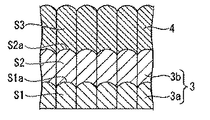
図1は、本発明で製造された磁気記録媒体の一例を示したものである。以下、本発明の磁気記録媒体の一例として、図1に示す磁気記録媒体を例に挙げて説明する。図1に示す磁気記録媒体は、非磁性基板1の上に、軟磁性下地層2と、配向制御層3と、垂直磁性層4と、保護層5と、潤滑層6とが順次積層された構造を有している。このうち、軟磁性下地層2と配向制御層3とが下地層を構成している。
FIG. 1 shows an example of a magnetic recording medium manufactured according to the present invention. Hereinafter, the magnetic recording medium shown in FIG. 1 will be described as an example of the magnetic recording medium of the present invention. In the magnetic recording medium shown in FIG. 1, a soft
「非磁性基板」
非磁性基板1としては、アルミニウムやアルミニウム合金などの金属材料からなる金属基板を用いてもよいし、ガラスや、セラミック、シリコン、シリコンカーバイド、カーボンなどの非金属材料からなる非金属基板を用いてもよい。また、非磁性基板1としては、これら金属基板や非金属基板の表面に、例えばメッキ法やスパッタリング法などを用いて、NiP層又はNiP合金層が形成されたものを用いてもよい。
"Non-magnetic substrate"
As the
ガラス基板としては、例えば、アモルファスガラスや結晶化ガラスなどを用いることができ、アモルファスガラスとしては、例えば、汎用のソーダライムガラスや、アルミノシリケートガラスなどを用いることができる。また、結晶化ガラスとしては、例えば、リチウム系結晶化ガラスなどを用いることができる。セラミック基板としては、例えば、汎用の酸化アルミニウムや、窒化アルミニウム、窒化珪素などを主成分とする焼結体、又はこれらの繊維強化物などを用いることができる。 As the glass substrate, for example, amorphous glass or crystallized glass can be used, and as the amorphous glass, for example, general-purpose soda lime glass or aluminosilicate glass can be used. In addition, as the crystallized glass, for example, lithium-based crystallized glass can be used. As the ceramic substrate, for example, general-purpose aluminum oxide, a sintered body mainly composed of aluminum nitride, silicon nitride, or the like, or a fiber reinforced material thereof can be used.
「軟磁性下地層」
非磁性基板の上には、軟磁性下地層2が形成される。軟磁性下地層2の形成方法は特に限られるものではなく、例えば、スパッタリング法などを用いることができる。
"Soft magnetic underlayer"
A soft
軟磁性下地層2は、磁気ヘッドから発生する磁束の基板面に対する垂直方向成分を大きくするために、また情報が記録される垂直磁性層4の磁化の方向をより強固に非磁性基板1と垂直な方向に固定するために設けられている。この作用は、特に記録再生用の磁気ヘッドとして垂直記録用の単磁極ヘッドを用いる場合に、より顕著なものとなる。
The soft
軟磁性下地層2としては、例えば、Feや、Ni、Coなどを含む軟磁性材料を用いることができる。具体的な軟磁性材料としては、例えば、CoFe系合金(CoFeTaZr、CoFeZrNbなど)、FeCo系合金(FeCo、FeCoVなど)、FeNi系合金(FeNi、FeNiMo、FeNiCr、FeNiSiなど)、FeAl系合金(FeAl、FeAlSi、FeAlSiCr、FeAlSiTiRu、FeAlOなど)、FeCr系合金(FeCr、FeCrTi、FeCrCuなど)、FeTa系合金(FeTa、FeTaC、FeTaNなど)、FeMg系合金(FeMgOなど)、FeZr系合金(FeZrNなど)、FeC系合金、FeN系合金、FeSi系合金、FeP系合金、FeNb系合金、FeHf系合金、FeB系合金などを挙げることができる。
As the soft
「配向制御層」
軟磁性下地層2の上には、配向制御層3が形成されている。配向制御層3は、垂直磁性層4の結晶粒を微細化し、記録再生特性を改善するものである。図1に示すように、本実施形態の配向制御層3は、軟磁性下地層2側に配置された第1配向制御層3aと、第1配向制御層3aの垂直磁性層4側に配置された第2配向制御層3bとからなる。
`` Orientation control layer ''
An
第1配向制御層3aは、配向制御層3の核発生密度を高めるためのものであり、配向制御層3を構成する柱状晶の核となる結晶を含むものである。本実施形態の第1配向制御層3aでは、図2に示すように、核となる結晶が成長してなる柱状晶S1の頂部に、ドーム状の凸部が形成されている。
The first
「垂直磁性層」
本願発明の垂直磁性層は、本願発明のターゲットを用いた、少なくとも1層以上のスパッタリング工程により形成されたグラニュラ磁性層を有し、このグラニュラ磁性層はCo合金を含む複数の磁性粒子及び前記複数の磁性粒子を分離する酸化物から構成される。そしてこのグラニュラ磁性層の形成に際しては酸化コバルトを含むターゲットを用いるため、磁性粒子の微細化、孤立化が図られ、また磁性粒子の粒界の拡大が図られている。
"Perpendicular magnetic layer"
The perpendicular magnetic layer of the present invention has a granular magnetic layer formed by at least one sputtering process using the target of the present invention, and the granular magnetic layer includes a plurality of magnetic particles including a Co alloy and the plurality of magnetic particles. It is comprised from the oxide which isolate | separates the magnetic particle. Since the granular magnetic layer is formed using a target containing cobalt oxide, the magnetic particles are miniaturized and isolated, and the grain boundaries of the magnetic particles are expanded.
本願発明で形成された垂直磁性層を図1により説明する。本願発明の垂直磁性層4は例えば第2配向制御層3bの上に形成されている。図1に示すように、垂直磁性層4は、例えば非磁性基板1側から、第1の磁性層4a、第2の磁性層7a、第3の磁性層4b、第4の磁性層7b、第5の磁性層4cを含むものである。この内、第1の磁性層4a、第2の磁性層7a、第3の磁性層4b、第4の磁性層7bの少なくとも1層は、CrおよびCoOを5モル%以上含み、酸化ホウ素を3モル%〜20モル%の範囲内で含み、気孔率が7%以下であるターゲットを用いて成膜することが好ましく、例えば、CoPt−SiO2(第1の磁性層4a)、CoCrPtB−SiO2(第2の磁性層7a)、CoPt−SiO2(第3の磁性層4b)、CoCrPtB−SiO2(第4の磁性層7b)とすることができる。この積層構造の場合、第2の磁性層7aと第4の磁性層7bが本願発明のターゲットを用いて成膜した層である。この2つの磁性層では微細化したCo系磁性粒子と、その磁性粒子の粒界幅を広げる非磁性酸化物が形成している。なお、第5の磁性層4cの好ましい構成については後述する。
The perpendicular magnetic layer formed in the present invention will be described with reference to FIG. The perpendicular
各磁性層4a、4b、7a、7bを構成する結晶粒子は、配向制御層3の第1配向制御層3aおよび第2配向制御層3bの柱状晶と連続した柱状晶として、配向制御層3上にエピタキシャル成長している。
Crystal grains constituting each of the
図3は、垂直磁性層を構成する磁性層の積層構造を拡大して示した断面図である。図3に示すように、垂直磁性層4を構成する磁性層は、グラニュラ構造の磁性層であり、Co、Cr、Pt等を含む磁性粒子(磁性を有した結晶粒子)42と、酸化物41とを含むものであることが好ましい。
FIG. 3 is an enlarged cross-sectional view showing the laminated structure of the magnetic layers constituting the perpendicular magnetic layer. As shown in FIG. 3, the magnetic layer constituting the perpendicular
酸化物41としては、例えばSi、Ta、Al、Ti、Mg、Co、Ceなどの酸化物を用いることが好ましい。その中でも特に、TiO2、SiO2などを好適に用いることができる。また、磁性層は、酸化物を2種類以上添加した複合酸化物からなることが好ましい。その中でも特に、SiO2−TiO2などを好適に用いることができる。
As the oxide 41, for example, an oxide such as Si, Ta, Al, Ti, Mg, Co, and Ce is preferably used. Among them, it can be suitably used such as
磁性粒子42は、磁性層中に分散していることが好ましい。また、磁性粒子42は、磁性層4a、4b、7a、7b更には磁性層4cを上下に貫いた柱状構造を形成していることが好ましい。このような構造を有することにより、磁性層の配向及び結晶性が良好なものとなり、結果として高密度記録に適した信号/ノイズ比(S/N比)が得られる。
The
柱状構造の磁性粒子42を有する垂直磁性層4を得るためには、磁性層に含まれる酸化物41の含有量及び磁性層の成膜条件が重要となる。磁性層に含まれる酸化物41の含有量は、磁性粒子42を構成する、例えばCo、Pt等の合金を1つの化合物として算出したモル総量に対して、3モル%以上18モル%以下であること
が好ましく、6モル%以上13モル%以下であることがより好ましい。
In order to obtain the perpendicular
磁性層中の酸化物41の含有量として上記範囲が好ましいのは、磁性層を形成した際に磁性粒子42の周りに酸化物41が析出し、磁性粒子42の孤立化及び微細化が可能となるためである。一方、酸化物41の含有量が上記範囲を超えた場合には、酸化物41が磁性粒子42中に残留し、磁性粒子42の配向性及び結晶性を損ねたり、磁性粒子42の上下に酸化物41が析出して、磁性粒子42が磁性層4a〜4cを上下に貫いてなる柱状構造が形成されなくなったりするため好ましくない。また、酸化物41の含有量が上記範囲未満である場合には、磁性粒子42の分離及び微細化が不十分となり、結果として記録再生時におけるノイズが増大し、高密度記録に適した信号/ノイズ比(S/N比)が得られなくなるため好ましくない。
磁性層中のPtの含有量は、5原子%以上25原子%以下であることが好ましい。
The content of the oxide 41 in the magnetic layer is preferably within the above range because the oxide 41 is deposited around the
The Pt content in the magnetic layer is preferably 5 atomic% or more and 25 atomic% or less.
Ptの含有量が5原子%未満であると、高密度記録に適した熱揺らぎ特性を得るために垂直磁性層4に必要な磁気異方性定数Kuが得られないため好ましくない。Ptの含有量が25原子%を超えると、磁性粒子42の内部に積層欠陥が生じ、その結果、磁気異方性定数Kuが低くなる。また、Ptの含有量が上記範囲を超えた場合、磁性粒子42中にfcc構造の層が形成され、結晶性及び配向性が損なわれるおそれがあるため好ましくない。
したがって、高密度記録に適した熱揺らぎ特性及び記録再生特性を得るためには、磁性層中Ptの含有量を上記範囲とすることが好ましい。
If the Pt content is less than 5 atomic%, the magnetic anisotropy constant Ku necessary for the perpendicular
Therefore, in order to obtain thermal fluctuation characteristics and recording / reproduction characteristics suitable for high-density recording, it is preferable to set the content of Pt in the magnetic layer within the above range.
磁性層の磁性粒子42には、Co、Cr、Ptの他に、B、Ta、Mo、Cu、Nd、W、Nb、Sm、Tb、Ru、Reの中から選ばれる1種類以上の元素が含まれていてもよい。この中でBは、ターゲットに含まれる酸化ホウ素の分解物からも供給される。上記元素を含むことにより、磁性粒子42の微細化を促進、又は結晶性や配向性を向上させることができ、より高密度記録に適した記録再生特性、熱揺らぎ特性を得る
ことができる。
In addition to Co, Cr, Pt, the
また、磁性粒子42中に含まれるCo、Ptの他の上記元素の合計の含有量は、10原子%以下であることが好ましい。上記元素の合計の含有量が10原子%を超えると、磁性粒子42中にhcp相以外の相が形成されるため、磁性粒子42の結晶性及び配向性が乱れ、結果として高密度記録に適した記録再生特性及び熱揺らぎ特性が得られないため好ましくない。
The total content of Co and Pt other than the above elements contained in the
垂直磁性層4を構成する磁性層4cは、本願発明のターゲットを用いて形成された層ではなく、図3に示すように、Coを含む磁性粒子(磁性を有した結晶粒子)42を含み、酸化物41を含まないものであることが好ましい。磁性層4c中の磁性粒子42は、磁性層4a中の磁性粒子42から柱状にエピタキシャル成長しているものであることが好ましい。この場合、磁性層4a〜4cの磁性粒子42が、各層において1対1に対応して、柱状にエピタキシャル成長することが好ましい。また、磁性層4bの磁性粒子42が磁性層4a中の磁性粒子42からエピタキシャル成長していることで、磁性層4bの磁性粒子42が微細化され、さらに結晶性及び配向性が向上したものとなる。
The
磁性層4c中のCrの含有量は、10原子%以上24原子%以下であることが好ましい。Crの含有量を上記範囲とすることで、データの再生時における出力を十分確保でき、更に良好な熱揺らぎ特性を得ることができる。一方、Crの含有量が上記範囲を超える場合、磁性層4cの磁化が小さくなり過ぎるため好ましくない。また、Cr含有量が上記範囲未満である場合には、磁性粒子42の分離及び微細化が十分に生じず、記録再生時のノイズが増大し、高密度記録に適した信号/ノイズ比(S/N比)が得られなくなるため好ましくない。
The content of Cr in the
垂直磁性層4の垂直保磁力(Hc)は、3000[Oe]以上とすることが好ましい。保磁力が3000[Oe]未満である場合には、記録再生特性、特に周波数特性が不良となり、また、熱揺らぎ特性も悪くなるため、高密度記録媒体として好ましくない。 垂直磁性層4の逆磁区核形成磁界(−Hn)は、1500[Oe]以上であることが好ましい。逆磁区核形成磁界(−Hn)が1500[Oe]未満である場合には、熱揺らぎ耐性に劣るため好ましくない。
The perpendicular coercive force (Hc) of the perpendicular
垂直磁性層4を構成する磁性粒子42の平均粒径は3〜12nmの範囲内、粒界幅は0.5〜4nmの範囲内であることが好ましく、特に本願発明では平均粒径を6nm以下、Co系磁性粒子の粒界幅は1.5nm以上とし、かつその磁性粒子の界面を鮮明(シャープ)なものとすることができる。前述のように、本願発明ではグラニュラ磁性層を形成するに際し、CoOを含むターゲットを用いているので、CoOの分離が促進されて、Co系磁性粒子の微細化、孤立化と粒界幅の拡大が得られ、その界面を鮮明(シャープ)なものとできる。磁性粒子42の平均粒径、粒界幅、磁性粒子の界面の鮮明さは、例えば垂直磁性層4をTEM(透過型電子顕微鏡)で観察し、観察像を画像処理することにより求めることができる。
The average particle size of the
「保護層」
垂直磁性層4上には保護層5が形成される。保護層5は、垂直磁性層4の腐食を防ぐとともに、磁気ヘッドが磁気記録媒体に接触したときの媒体表面の損傷を防ぐためのものである。保護層5としては、従来公知の材料を使用することができ、例えばC、SiO2、ZrO2を含むものを使用することが可能である。保護層5の厚みは、1〜10nmとすることが、磁気ヘッドと磁気記録媒体との距離を小さくできるので高記録密度の点から好ましい。保護層5は、例えば、CVD(化学気相成長)法などを用いて形成される。
"Protective layer"
A protective layer 5 is formed on the perpendicular
「潤滑層」
保護層5上には潤滑層6が形成される。潤滑層6には、例えば、パーフルオロポリエーテル、フッ素化アルコール、フッ素化カルボン酸などの潤滑剤を用いることが好ましい。潤滑層6は、例えば、ディッピング法などを用いて形成される。
"Lubrication layer"
A lubricating layer 6 is formed on the protective layer 5. For the lubricating layer 6, it is preferable to use a lubricant such as perfluoropolyether, fluorinated alcohol, fluorinated carboxylic acid, or the like. The lubricating layer 6 is formed using, for example, a dipping method.
(磁気記録再生装置)
図4は、本発明を適用した磁気記録再生装置の一例を示すものである。
この磁気記録再生装置は、図1に示す構成を有する磁気記録媒体50と、磁気記録媒体50を回転駆動させる媒体駆動部51と、磁気記録媒体50に情報を記録再生する磁気ヘッド52と、この磁気ヘッド52を磁気記録媒体50に対して相対運動させるヘッド駆動部53と、記録再生信号処理系54とを備えている。
(Magnetic recording / reproducing device)
FIG. 4 shows an example of a magnetic recording / reproducing apparatus to which the present invention is applied.
This magnetic recording / reproducing apparatus includes a
記録再生信号処理系54は、外部から入力されたデータを処理して記録信号を磁気ヘッド52に送り、磁気ヘッド52からの再生信号を処理してデータを外部に送ることが可能となっている。本発明を適用した磁気記録再生装置に用いる磁気ヘッド52には、再生素子として巨大磁気抵抗効果(GMR)を利用したGMR素子などを有した、より高記録密度に適した磁気ヘッドを用いることができる。
The recording / reproduction
図4に示す磁気記録再生装置は、本発明の磁気記録媒体の一例である図1に示す磁気記録媒体50と、磁気記録媒体50に対する情報の記録再生を行う磁気ヘッド52とを備えるものであるので、高密度記録に適した信号/ノイズ比(S/N比)、記録特性(OW)が得られる磁気記録媒体を備えた優れたものとなる。
The magnetic recording / reproducing apparatus shown in FIG. 4 includes the
以下、実施例により本発明の効果をより明らかなものとする。なお、本発明は、以下の実施例に限定されるものではなく、その要旨を変更しない範囲で適宜変更して実施することができる。 Hereinafter, the effects of the present invention will be made clearer by examples. In addition, this invention is not limited to a following example, In the range which does not change the summary, it can change suitably and can implement.
(実施例のターゲットの製造)
次の方法にて、CoCrPtB−SiO2からなる組成のターゲットを製造した。
(Manufacture of the target of an Example)
A target having a composition made of CoCrPtB—SiO 2 was produced by the following method.
先ず、ガスアトマイズ法により、Co16Pt、CoO、Cr、B2O3、SiO2粉末を製造した。粉末の平均粒径は約5μmとした。この粉末を、CoOを8モル%、Crを7モル%、SiO2を7モル%とし、B2O3を0〜6モル%の範囲内で変化させ、残部をCo16Ptとして混合し、モールドに入れ予備成形した後、800℃、圧力200Kgf/cm2、アルゴン雰囲気中で1時間のホットプレス処理し、その焼結体をターゲット形状に切り出しターゲットを製造した。得られたターゲットの気孔率を図5に示すが、酸化ホウ素を3モル%以上含有させることで、気孔率が7%以下のターゲットを製造できた。なお別途、酸化ホウ素を20モル%含有させる実験を行ったところ気孔率2%未満が達成された。 First, by a gas atomizing method was prepared Co16Pt, CoO, Cr, B 2 O 3, a SiO 2 powder. The average particle size of the powder was about 5 μm. The powder was mixed with 8 mol% CoO, 7 mol% Cr, 7 mol% SiO 2 and B 2 O 3 within a range of 0 to 6 mol%, and the remainder was mixed as Co16Pt. After pre-molding, hot pressing was performed in an argon atmosphere at 800 ° C. and a pressure of 200 kgf / cm 2 for 1 hour, and the sintered body was cut into a target shape to produce a target. The porosity of the obtained target is shown in FIG. 5, and a target having a porosity of 7% or less could be produced by containing 3 mol% or more of boron oxide. Separately, when an experiment was made to contain 20 mol% of boron oxide, a porosity of less than 2% was achieved.
(実施例)
以下に示す製造方法により、実施例の磁気記録媒体を作製し、評価した。なお、本実施例のグラニュラ磁性層は、上記のターゲットの製造において、B2O3を5.5モル%として得られた気孔率2%のターゲットを用いた。
(Example)
The magnetic recording media of the examples were manufactured and evaluated by the manufacturing methods shown below. Incidentally, granular magnetic layer of the present example, in the preparation of the target, with porosity of 2% target obtained with B 2 O 3 as a 5.5 mole%.
まず、洗浄済みのガラス基板(コニカミノルタ社製、外形2.5インチ)を、DCマグネトロンスパッタ装置(アネルバ社製C−3040)の成膜チャンバ内に収容して、到達真空度1×10⁻⁵Paとなるまで成膜チャンバ内を排気した後、このガラス基板の上に、Crターゲットを用いて層厚10nmの密着層を成膜した。 First, a cleaned glass substrate (manufactured by Konica Minolta, 2.5 inch outer diameter) is housed in a film forming chamber of a DC magnetron sputtering apparatus (C-3040, manufactured by Anelva), and the ultimate vacuum is 1 × 10 −3. After evacuating the film formation chamber to 5 Pa, an adhesion layer having a thickness of 10 nm was formed on the glass substrate using a Cr target.
このようにして得られた密着層の上に、Co−20Fe−5Zr−5Ta{Fe含有量20原子%、Zr含有量5原子%、Ta含有量5原子%、残部Co}のターゲットを用いて100℃以下の基板温度で、層厚25nmの軟磁性層を成膜し、この上にRu層を層厚0.7nmで成膜し、さらにCo−20Fe−5Zr−5Taの軟磁性層を層厚25nmで成膜し、これを軟磁性下地層とした。 On the adhesion layer thus obtained, a target of Co-20Fe-5Zr-5Ta {Fe content 20 atomic%, Zr content 5 atomic%, Ta content 5 atomic%, balance Co} is used. A soft magnetic layer having a layer thickness of 25 nm is formed at a substrate temperature of 100 ° C. or less, a Ru layer is formed thereon with a layer thickness of 0.7 nm, and a soft magnetic layer of Co-20Fe-5Zr-5Ta is further formed. A film having a thickness of 25 nm was formed as a soft magnetic underlayer.
次に、軟磁性下地層の上にスパッタリング法により配向制御層を形成した。配向制御層としては、軟磁性下地層側に配置されたRuからなる第1配向制御層と、第1配向制御層の垂直磁性層側に配置されたRuからなる第2配向制御層をスパッタリング法により形成した。なお、第1配向制御層のスパッタリングガス圧は3Pa、第2配向制御層のスパッタリングガス圧は10Paとした。 Next, an orientation control layer was formed on the soft magnetic underlayer by a sputtering method. As the orientation control layer, a first orientation control layer made of Ru arranged on the soft magnetic underlayer side and a second orientation control layer made of Ru arranged on the perpendicular magnetic layer side of the first orientation control layer are sputtered. Formed by. The sputtering gas pressure of the first orientation control layer was 3 Pa, and the sputtering gas pressure of the second orientation control layer was 10 Pa.
その後、配向制御層上に、上記のターゲットを用いたグラニュラ構造の垂直磁性層を形成した。スパッタリングガス圧を2Paとして層厚4nmで成膜した。なお、成膜されたグラニュラ構造の垂直磁性層の組成は、92(Co10Cr14Pt5B)−8(SiO2)であった。 Thereafter, a perpendicular magnetic layer having a granular structure using the above target was formed on the orientation control layer. The sputtering gas pressure was set to 2 Pa and the film was formed with a layer thickness of 4 nm. The composition of the formed perpendicular magnetic layer having a granular structure was 92 (Co10Cr14Pt5B) -8 (SiO 2 ).
次に、グラニュラ構造の磁性層の上に、Ruからなる非磁性層を層厚0.3nmで成膜した。 Next, a nonmagnetic layer made of Ru was formed with a layer thickness of 0.3 nm on the magnetic layer having a granular structure.
次に、非磁性層の上に、Co20Cr14Pt3B{Cr含有量20原子%、Pt含有量14原子%、B含有量3原子%、残部Co}からなるターゲットを用いて、スパッタリングガス圧を0.6Paとして磁性層を層厚7nmで成膜した。
Next, a sputtering gas pressure is set to 0.6 Pa on a nonmagnetic layer using a target made of Co20Cr14Pt3B {Cr content 20 atomic%, Pt content 14 atomic%,
次に、CVD法により層厚3.0nmの保護層を成膜し、次いで、ディッピング法によりパーフルオロポリエーテルからなる潤滑層を成膜し磁気記録媒体を作製した。 Next, a protective layer having a thickness of 3.0 nm was formed by a CVD method, and then a lubricating layer made of perfluoropolyether was formed by a dipping method to produce a magnetic recording medium.
このようにして得られた磁気記録媒体について、米国GUZIK社製のリードライトアナライザRWA1632及びスピンスタンドS1701MPを用いて、記録再生特性として信号/ノイズ比(S/N比)、記録特性(OW)の評価を行った。 For the magnetic recording medium thus obtained, a signal / noise ratio (S / N ratio) and a recording characteristic (OW) as recording / reproducing characteristics using a read / write analyzer RWA1632 and spin stand S1701MP manufactured by GUZIK, USA. Evaluation was performed.
なお、磁気ヘッドには、書き込み側にシングルポール磁極を用い、読み出し側にTMR素子を用いたヘッドを使用した。 As the magnetic head, a head using a single pole magnetic pole on the writing side and a TMR element on the reading side was used.
信号/ノイズ比(S/N比)については、記録密度750kFCIとして測定した。 The signal / noise ratio (S / N ratio) was measured at a recording density of 750 kFCI.
記録特性(OW)については、先ず、750kFCIの信号を書き込み、次いで100kFCIの信号を上書し、周波数フィルターにより高周波成分を取り出し、その残留割合によりデータの書き込み能力を評価した。その結果、S/N比は14.10dB、OWは42.4dBと電磁変換特性に優れていた。また評価後、グラニュラ磁性層のTEM観察を行ったところ、磁性粒子の平均粒径は5.5nm、粒界幅は1.6nmであり、磁性粒子の界面は鮮明であった。 Regarding the recording characteristics (OW), first, a 750 kFCI signal was written, then a 100 kFCI signal was overwritten, a high frequency component was taken out by a frequency filter, and the data writing ability was evaluated by the residual ratio. As a result, the S / N ratio was 14.10 dB and OW was 42.4 dB, which was excellent in electromagnetic conversion characteristics. After the evaluation, the granular magnetic layer was observed by TEM. As a result, the average particle size of the magnetic particles was 5.5 nm, the grain boundary width was 1.6 nm, and the interface of the magnetic particles was clear.
(比較例のターゲットの製造)
次の方法にて、92(71Co10Cr14Pt5B)−8(SiO2)からなる組成のターゲットを製造した。
(Manufacture of target of comparative example)
A target having a composition composed of 92 (71Co10Cr14Pt5B) -8 (SiO 2 ) was produced by the following method.
先ず、ガスアトマイズ法により、Co、Cr、Pt粉末を製造した。粉末の平均粒径は約5μmとした。この粉末に平均粒径約5μmの、B、SiO2粉末を加え、92(71Co10Cr14Pt5B)−8(SiO2)の組成比とし、この混合粉末をモールドに入れ予備成形した後、1200℃、圧力200Kgf/cm2、真空中で3時間のホットプレス処理し、その焼結体をターゲット形状に切り出しターゲットを製造した。得られたターゲットの気孔率は2%であった。 First, Co, Cr, and Pt powders were manufactured by a gas atomization method. The average particle size of the powder was about 5 μm. B, SiO 2 powder having an average particle diameter of about 5 μm was added to this powder to give a composition ratio of 92 (71Co10Cr14Pt5B) -8 (SiO 2 ). After this mixed powder was pre-molded into a mold, 1200 ° C., pressure 200 kgf / Cm 2 , hot pressing for 3 hours in a vacuum, and the sintered body was cut into a target shape to produce a target. The porosity of the obtained target was 2%.
(比較例)
実施例と同様に磁気記録媒体を製造したが、グラニュラ構造の垂直磁性層の成膜には、92(71Co10Cr14Pt5B)−8(SiO2)からなる組成の前述の比較例のターゲットを用いた。
(Comparative example)
A magnetic recording medium was manufactured in the same manner as in the example, but the target of the above-mentioned comparative example having a composition of 92 (71Co10Cr14Pt5B) -8 (SiO 2 ) was used for forming the perpendicular magnetic layer having a granular structure.
得られた磁気記録媒体の電磁変換特性は、S/N比は13.60dB、OWは41.5dBであり実施例より劣っていた。また評価後、グラニュラ磁性層のTEM観察を行ったところ、磁性粒子の平均粒径は6.1nm、粒界幅は1.9nmであった。 The magnetic conversion characteristics of the obtained magnetic recording medium were inferior to those of the examples, with an S / N ratio of 13.60 dB and an OW of 41.5 dB. After the evaluation, the granular magnetic layer was observed with a TEM. The average particle size of the magnetic particles was 6.1 nm, and the grain boundary width was 1.9 nm.
1…非磁性基板、2…軟磁性下地層、3…配向制御層、3a…第1配向制御層、3b…第2配向制御層、4…垂直磁性層、7…垂直磁性層、4a…第1の磁性層、7a…第2の磁性層、4b…第3の磁性層、7b…第4の磁性層、4c…第5の磁性層、5…保護層、6…潤滑層、15…酸化物、S1、S2、S3…柱状晶、S1a…凹凸面、41…酸化物、42…磁性粒子、50…磁気記録媒体、51…媒体駆動部、52…磁気ヘッド、53…ヘッド駆動部、54…記録再生信号処理系。
DESCRIPTION OF
Claims (6)
Priority Applications (1)
| Application Number | Priority Date | Filing Date | Title |
|---|---|---|---|
| JP2010174208A JP5660710B2 (en) | 2010-08-03 | 2010-08-03 | Target manufacturing method, magnetic recording medium manufacturing method |
Applications Claiming Priority (1)
| Application Number | Priority Date | Filing Date | Title |
|---|---|---|---|
| JP2010174208A JP5660710B2 (en) | 2010-08-03 | 2010-08-03 | Target manufacturing method, magnetic recording medium manufacturing method |
Publications (3)
| Publication Number | Publication Date |
|---|---|
| JP2012033247A JP2012033247A (en) | 2012-02-16 |
| JP2012033247A5 JP2012033247A5 (en) | 2014-03-06 |
| JP5660710B2 true JP5660710B2 (en) | 2015-01-28 |
Family
ID=45846483
Family Applications (1)
| Application Number | Title | Priority Date | Filing Date |
|---|---|---|---|
| JP2010174208A Active JP5660710B2 (en) | 2010-08-03 | 2010-08-03 | Target manufacturing method, magnetic recording medium manufacturing method |
Country Status (1)
| Country | Link |
|---|---|
| JP (1) | JP5660710B2 (en) |
Families Citing this family (5)
| Publication number | Priority date | Publication date | Assignee | Title |
|---|---|---|---|---|
| JP6144570B2 (en) * | 2013-08-05 | 2017-06-07 | 昭和電工株式会社 | Magnetic recording medium manufacturing method, magnetic recording medium, and magnetic recording / reproducing apparatus |
| WO2017141557A1 (en) * | 2016-02-19 | 2017-08-24 | Jx金属株式会社 | Sputtering target for magnetic recording medium, and magnetic thin film |
| CN107303127B (en) * | 2016-04-25 | 2019-08-09 | 佛山市顺德区美的电热电器制造有限公司 | A kind of cooking pot tool and its manufacturing method |
| TWI671418B (en) * | 2017-09-21 | 2019-09-11 | 日商Jx金屬股份有限公司 | Sputtering target, manufacturing method of laminated film, laminated film and magnetic recording medium |
| JPWO2021085410A1 (en) * | 2019-11-01 | 2021-05-06 |
Family Cites Families (4)
| Publication number | Priority date | Publication date | Assignee | Title |
|---|---|---|---|---|
| JP2001011601A (en) * | 1999-07-01 | 2001-01-16 | Nikko Materials Co Ltd | Material for protective film for optical media |
| JP2006176810A (en) * | 2004-12-21 | 2006-07-06 | Mitsubishi Materials Corp | METHOD FOR PRODUCING CoCrPt-SiO2 SPUTTERING TARGET FOR DEPOSITING MAGNETIC RECORDING FILM |
| JP2009132976A (en) * | 2007-11-30 | 2009-06-18 | Mitsubishi Materials Corp | Sputtering target for depositing perpendicular magnetic recording medium film having low relative magnetic permeability |
| SG172395A1 (en) * | 2008-12-26 | 2011-08-29 | Mitsui Mining & Smelting Co | Sputtering target and method of forming film |
-
2010
- 2010-08-03 JP JP2010174208A patent/JP5660710B2/en active Active
Also Published As
| Publication number | Publication date |
|---|---|
| JP2012033247A (en) | 2012-02-16 |
Similar Documents
| Publication | Publication Date | Title |
|---|---|---|
| JP4185391B2 (en) | Magnetic recording medium, manufacturing method thereof, and magnetic recording / reproducing apparatus | |
| WO2009119708A1 (en) | Vertical magnetic recording medium and method for making vertical magnetic recording medium | |
| JP4219941B2 (en) | Magnetic recording medium, manufacturing method thereof, and magnetic recording / reproducing apparatus | |
| WO2012157600A1 (en) | Magnetic recording medium, manufacturing method thereof, and magnetic record/play device | |
| JP5536540B2 (en) | Magnetic recording medium and magnetic recording / reproducing apparatus | |
| JP5775720B2 (en) | Magnetic recording medium manufacturing method and magnetic recording / reproducing apparatus | |
| JP5894780B2 (en) | Method for manufacturing magnetic recording medium | |
| JP5660710B2 (en) | Target manufacturing method, magnetic recording medium manufacturing method | |
| JP6265529B2 (en) | Magnetic recording medium manufacturing method, magnetic recording medium, and magnetic recording / reproducing apparatus | |
| JP6144570B2 (en) | Magnetic recording medium manufacturing method, magnetic recording medium, and magnetic recording / reproducing apparatus | |
| JP5325945B2 (en) | Perpendicular magnetic recording medium and magnetic recording / reproducing apparatus | |
| JP5890756B2 (en) | Magnetic recording medium and magnetic storage device | |
| JP2014099226A (en) | Servo information recording method and magnetic storage device | |
| JP4472767B2 (en) | Magnetic recording medium and magnetic recording / reproducing apparatus | |
| JP2011123976A (en) | Method for manufacturing magnetic recording medium and magnetic recording and reproducing device | |
| JP5244679B2 (en) | Method for manufacturing magnetic recording medium | |
| JP5232730B2 (en) | Magnetic recording medium, method of manufacturing magnetic recording medium, and magnetic recording / reproducing apparatus | |
| JP2014010851A (en) | Magnetic recording medium, and magnetic storage device | |
| JP2013246856A (en) | Magnetic recording medium and magnetic storage apparatus | |
| JP2011123977A (en) | Magnetic recording medium and magnetic recording and reproducing device | |
| JP5677789B2 (en) | Magnetic recording medium and magnetic recording / reproducing apparatus | |
| JP6566907B2 (en) | Magnetic recording medium and magnetic recording / reproducing apparatus | |
| JP5771427B2 (en) | Magnetic recording medium manufacturing method and magnetic recording / reproducing apparatus | |
| JP4852180B2 (en) | Method for manufacturing perpendicular magnetic recording medium | |
| JP2014049171A (en) | Magnetic recording medium, and magnetic recording and reproducing device |
Legal Events
| Date | Code | Title | Description |
|---|---|---|---|
| A621 | Written request for application examination |
Free format text: JAPANESE INTERMEDIATE CODE: A621 Effective date: 20130531 |
|
| A521 | Request for written amendment filed |
Free format text: JAPANESE INTERMEDIATE CODE: A523 Effective date: 20140121 |
|
| A977 | Report on retrieval |
Free format text: JAPANESE INTERMEDIATE CODE: A971007 Effective date: 20140228 |
|
| A131 | Notification of reasons for refusal |
Free format text: JAPANESE INTERMEDIATE CODE: A131 Effective date: 20140331 |
|
| A521 | Request for written amendment filed |
Free format text: JAPANESE INTERMEDIATE CODE: A523 Effective date: 20140416 |
|
| TRDD | Decision of grant or rejection written | ||
| A01 | Written decision to grant a patent or to grant a registration (utility model) |
Free format text: JAPANESE INTERMEDIATE CODE: A01 Effective date: 20141128 |
|
| A61 | First payment of annual fees (during grant procedure) |
Free format text: JAPANESE INTERMEDIATE CODE: A61 Effective date: 20141201 |
|
| R150 | Certificate of patent or registration of utility model |
Ref document number: 5660710 Country of ref document: JP Free format text: JAPANESE INTERMEDIATE CODE: R150 |
|
| S111 | Request for change of ownership or part of ownership |
Free format text: JAPANESE INTERMEDIATE CODE: R313111 |
|
| R350 | Written notification of registration of transfer |
Free format text: JAPANESE INTERMEDIATE CODE: R350 |
|
| S531 | Written request for registration of change of domicile |
Free format text: JAPANESE INTERMEDIATE CODE: R313531 |
|
| R350 | Written notification of registration of transfer |
Free format text: JAPANESE INTERMEDIATE CODE: R350 |