JP5659020B2 - Multiple beam drilling system - Google Patents
Multiple beam drilling system Download PDFInfo
- Publication number
- JP5659020B2 JP5659020B2 JP2010541887A JP2010541887A JP5659020B2 JP 5659020 B2 JP5659020 B2 JP 5659020B2 JP 2010541887 A JP2010541887 A JP 2010541887A JP 2010541887 A JP2010541887 A JP 2010541887A JP 5659020 B2 JP5659020 B2 JP 5659020B2
- Authority
- JP
- Japan
- Prior art keywords
- beams
- holes
- sub
- pulse
- energy
- Prior art date
- Legal status (The legal status is an assumption and is not a legal conclusion. Google has not performed a legal analysis and makes no representation as to the accuracy of the status listed.)
- Active
Links
Images


Classifications
-
- B—PERFORMING OPERATIONS; TRANSPORTING
- B23—MACHINE TOOLS; METAL-WORKING NOT OTHERWISE PROVIDED FOR
- B23K—SOLDERING OR UNSOLDERING; WELDING; CLADDING OR PLATING BY SOLDERING OR WELDING; CUTTING BY APPLYING HEAT LOCALLY, e.g. FLAME CUTTING; WORKING BY LASER BEAM
- B23K26/00—Working by laser beam, e.g. welding, cutting or boring
- B23K26/02—Positioning or observing the workpiece, e.g. with respect to the point of impact; Aligning, aiming or focusing the laser beam
- B23K26/04—Automatically aligning, aiming or focusing the laser beam, e.g. using the back-scattered light
-
- B—PERFORMING OPERATIONS; TRANSPORTING
- B23—MACHINE TOOLS; METAL-WORKING NOT OTHERWISE PROVIDED FOR
- B23K—SOLDERING OR UNSOLDERING; WELDING; CLADDING OR PLATING BY SOLDERING OR WELDING; CUTTING BY APPLYING HEAT LOCALLY, e.g. FLAME CUTTING; WORKING BY LASER BEAM
- B23K26/00—Working by laser beam, e.g. welding, cutting or boring
- B23K26/02—Positioning or observing the workpiece, e.g. with respect to the point of impact; Aligning, aiming or focusing the laser beam
- B23K26/06—Shaping the laser beam, e.g. by masks or multi-focusing
- B23K26/067—Dividing the beam into multiple beams, e.g. multi-focusing
- B23K26/0676—Dividing the beam into multiple beams, e.g. multi-focusing into dependently operating sub-beams, e.g. an array of spots with fixed spatial relationship or for performing simultaneously identical operations
-
- G—PHYSICS
- G01—MEASURING; TESTING
- G01B—MEASURING LENGTH, THICKNESS OR SIMILAR LINEAR DIMENSIONS; MEASURING ANGLES; MEASURING AREAS; MEASURING IRREGULARITIES OF SURFACES OR CONTOURS
- G01B11/00—Measuring arrangements characterised by the use of optical techniques
- G01B11/26—Measuring arrangements characterised by the use of optical techniques for measuring angles or tapers; for testing the alignment of axes
-
- G—PHYSICS
- G02—OPTICS
- G02B—OPTICAL ELEMENTS, SYSTEMS OR APPARATUS
- G02B26/00—Optical devices or arrangements for the control of light using movable or deformable optical elements
- G02B26/08—Optical devices or arrangements for the control of light using movable or deformable optical elements for controlling the direction of light
Landscapes
- Physics & Mathematics (AREA)
- Optics & Photonics (AREA)
- Engineering & Computer Science (AREA)
- Plasma & Fusion (AREA)
- Mechanical Engineering (AREA)
- General Physics & Mathematics (AREA)
- Laser Beam Processing (AREA)
- Mechanical Light Control Or Optical Switches (AREA)
- Length Measuring Devices By Optical Means (AREA)
- Lasers (AREA)
Description
(関連出願の相互参照)
2008年1月10日付け米国仮特許出願第61/020,273号「多重レーザ・ビーム位置決めおよびエネルギー配給システム」(Multiple Laser Beam Positioning and Energy Delivery System)を参照して,その開示内容をこの明細書中に参考として援用するとともに,その優先権を米国特許法施行規則(CFR)第1.78条(a)(4)項および(5)(i)項に基づいて主張する。
(Cross-reference of related applications)
Reference is made to US Provisional Patent Application No. 61 / 020,273 “Multiple Laser Beam Positioning and Energy Delivery System” dated January 10, 2008, the disclosure of which is incorporated herein by reference. Incorporated as a reference in the text, and claims priority based on section 1.78 (a) (4) and (5) (i) of the United States Patent Act Enforcement Regulations (CFR).
本願は,同日出願され,この発明の譲受人に譲渡されたPCT特許出願「多重ミラー較正システム」(Multiple Mirror Calibration System)に関連し,その開示内容についてもこの明細書中に参考として援用する。 This application is related to the PCT patent application “Multiple Mirror Calibration System” filed on the same day and assigned to the assignee of the present invention, the disclosure of which is also incorporated herein by reference.
この発明は包括的には穿孔装置(drilling apparatus)に関し,具体的にはレーザ・ビームを用いた複数孔(multiple holes)の穿孔に関する。 The present invention relates generally to a drilling apparatus, and more particularly to drilling multiple holes using a laser beam.
長年にわたって,基板のような対象物の穿孔,溶融,または切断等を目的に動作する製造システムにおいてレーザ・ビームが利用されている。このようなシステムでは製造時間を短縮するために多重レーザ・ビーム(multiple laser beams)を使用することができる。しかしながら,穿孔に多重ビームを使用する周知のシステムの動作の柔軟性を向上させる必要がある。 For many years, laser beams have been used in manufacturing systems that operate for the purpose of drilling, melting, or cutting objects such as substrates. In such a system multiple laser beams can be used to reduce manufacturing time. However, there is a need to improve the flexibility of operation of known systems that use multiple beams for drilling.
この発明は,種々同時性(様々な同時性)をもって(with varying simultaneity),基板にレーザ穿孔を行う改良されたシステムおよび方法を提供する。 The present invention provides an improved system and method for laser drilling a substrate with varying simultaneity.
この発明の好適な実施形態によると,レーザを動作させて,ビーム・パルスがあるトータル・エネルギー(a total energy)を有する,単一の出力ビーム(a single output beam)を生成し,上記単一出力ビームを時間経過の中で(to an extent which varies over time)複数のビームに分割し,上記複数のビームを基板上の複数の穿孔位置に当てる,種々同時性をもって基板にレーザ穿孔を行う方法であって,上記トータル・エネルギーの第1の割合(比率,部分,フラクション)(a first fraction)を占めるパルス・エネルギーを有する上記複数のビームのうちの対応する複数のビームを用いて(using corresponding ones of the plural beams),複数孔の第1の部分(first parts of multiple holes)を同時穿孔し,その後,上記第1の割合と異なる,上記トータル・エネルギーの少なくとも第2の割合(比率,部分,フラクション)(a second fraction)を占めるパルス・エネルギーをそれぞれが有する上記複数のビームのうちの少なくとも1つのビームを用いて,上記複数孔の少なくとも1つの孔の少なくとも1つの第2の部分(at least one second part of at least one of said multiple holes)を穿孔することを含む方法が提供される。 According to a preferred embodiment of the invention, the laser is operated to produce a single output beam having a total energy with a beam pulse, and the single A method of performing laser drilling on a substrate with various simultaneity, by dividing the output beam into multiple extents over time and applying the multiple beams to multiple drilling positions on the substrate. And using corresponding ones of the plurality of beams having pulse energy occupying a first fraction of the total energy (ratio, fraction, fraction). ones of the plural beams), the first parts of multiple holes are drilled at the same time, and then differ from the first ratio, where the total energy is low At least one of the plurality of holes using at least one of the plurality of beams each having a pulse energy occupying a second fraction (ratio, portion, fraction). A method is provided that includes drilling at least one second part of at least one of said multiple holes.
この発明の好適な実施形態によると,上記第1の割合は上記複数孔の数の関数(a function)である。 According to a preferred embodiment of the invention, the first ratio is a function of the number of holes.
この発明の好適な実施形態によると,上記第2の割合は上記少なくとも第2の部分が穿孔された上記複数孔の数の関数である。 According to a preferred embodiment of the invention, the second proportion is a function of the number of the plurality of holes in which the at least second portion is perforated.
また,この発明の好適な実施形態によると,レーザを動作させて,あるトータル・パワー(a total power)を有する単一の出力ビームを生成し,上記単一出力ビームを時間経過の中で複数のビームに分割し,上記複数のビームを基板上の複数の穿孔位置に当てる,種々同時性をもって基板にレーザ穿孔を行う方法であって,上記トータル・パワーの第1の割合(比率,部分,フラクション)を占めるビーム・パワーを有する上記複数のビームのうちの対応する複数のビームを用いて複数孔の第1の部分を同時穿孔し,その後,上記第1の割合と異なる,上記トータル・パワーの少なくとも第2の割合を占めるビーム・パワーをそれぞれが有する上記複数のビームのうちの少なくとも1つのビームを用いて,上記複数孔の少なくとも1つの孔の少なくとも1つの第2の部分を穿孔する方法が提供される。 According to a preferred embodiment of the present invention, a laser is operated to generate a single output beam having a total power, and a plurality of the single output beams are used over time. A plurality of beams are applied to a plurality of drilling positions on the substrate, and laser drilling is performed on the substrate with various simultaneity, wherein the first ratio (ratio, part, The first portion of the plurality of holes is simultaneously drilled using the corresponding plurality of beams having a beam power occupying a fraction), and then the total power different from the first ratio Using at least one of the plurality of beams, each having a beam power occupying at least a second fraction of at least one of the plurality of holes. A method is provided for drilling at least one second portion.
この発明の好適な実施形態によると,上記第1の割合は上記複数孔の数の関数である。 According to a preferred embodiment of the present invention, the first ratio is a function of the number of the plurality of holes.
この発明の好適な実施形態によると,上記第2の割合は上記少なくとも第2の部分が穿孔された上記複数孔の数の関数である。 According to a preferred embodiment of the invention, the second proportion is a function of the number of the plurality of holes in which the at least second portion is perforated.
好適には,上記単一出力ビームが,あるパルス繰返速度で(at a pulse repetition rate)生成された単一ビーム・パルス・エネルギー(single beam pulse energies)を有する複数のパルス(pulses)を含み,複数孔の第1の部分を穿孔する上記複数のビームのうちの対応する複数のビームが,上記パルス繰返速度と,上記単一ビーム・パルス・エネルギーの上記第1の割合を占めるパルス・エネルギーとを有する複数のパルスを含む。また,上記複数孔の少なくとも1つの孔の少なくとも1つの第2の部分を穿孔する上記複数のビームのうちの少なくとも1つのビームが,上記パルス繰返速度と,上記単一ビーム・パルス・エネルギーの少なくとも上記第2の割合を占めるパルス・エネルギーとを有する複数のパルスを含む。あるいは,上記複数孔の少なくとも1つの孔の少なくとも1つの第2の部分を穿孔する上記複数のビームのうちの少なくとも1つのビームが,上記パルス繰返速度の約数(a sub-multiple of the pulse repetition rate)と,上記単一ビーム・パルス・エネルギーの関数であるパルス・エネルギー(pulse energies which are a function of the single beam pulse energies)とを有する複数のパルスを含み,上記約数および関数が上記第2の割合に応じて選択される。 Preferably, the single output beam comprises a plurality of pulses having single beam pulse energies generated at a pulse repetition rate. , The corresponding plurality of the plurality of beams perforating the first portion of the plurality of holes is the pulse repetition rate and the pulse rate occupying the first ratio of the single beam pulse energy. A plurality of pulses having energy. Also, at least one of the plurality of beams that drills at least one second portion of at least one of the plurality of holes may include the pulse repetition rate and the single beam pulse energy. And a plurality of pulses having pulse energy occupying at least the second ratio. Alternatively, at least one of the plurality of beams that pierces at least one second portion of at least one of the plurality of holes is a sub-multiple of the pulse rate. a plurality of pulses having a repetition rate and a pulse energy that is a function of the single beam pulse energies, wherein the divisor and function are It is selected according to the second ratio.
この発明の好適な実施形態によると,上記単一の出力ビームは,あるパルス繰返速度で生成された単一ビーム・パルス・エネルギーを有する複数のパルスを含み,複数孔の第1の部分を穿孔する上記複数のビームのうちの対応する複数のビームは,上記第1の割合に応じて選択された上記パルス繰返速度の第1の約数と,上記単一ビーム・パルス・エネルギーの第1の関数であるパルス・エネルギーとを有する複数のパルスを含む。また,上記複数孔の少なくとも1つの孔の少なくとも1つの第2の部分を穿孔する上記複数のビームの少なくとも1つのビームは,上記パルス繰返速度の第2の約数と,上記単一ビーム・パルス・エネルギーの第2の関数であるパルス・エネルギーとを有する複数のパルスを含み,上記第2の約数および第2の関数が上記第2の割合に応じて選択される。 According to a preferred embodiment of the present invention, the single output beam includes a plurality of pulses having a single beam pulse energy generated at a pulse repetition rate, and includes a first portion of the plurality of holes. A corresponding plurality of the plurality of beams to be drilled includes a first divisor of the pulse repetition rate selected according to the first ratio and a first beam pulse energy first. A plurality of pulses having a pulse energy that is a function of unity. The at least one beam of the plurality of beams that pierces at least one second portion of the at least one hole of the plurality of holes includes a second divisor of the pulse repetition rate, the single beam A plurality of pulses having a pulse energy that is a second function of the pulse energy, wherein the second divisor and the second function are selected according to the second ratio.
この発明は,図面と併せて示した実施形態に関する以下の詳細な説明を参照すれば,より深い理解が得られる。図面の簡単な説明は,以下の通りである。 The invention can be better understood with reference to the following detailed description of the embodiments presented in conjunction with the drawings. A brief description of the drawings follows.
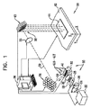
図1を参照して,図1はこの発明の実施形態による多重穿孔装置20を模式的に示す概略図である。装置20は,典型的には上記装置のオペレータによって操作される処理ユニット36において,その全体が制御される。
Referring to FIG. 1, FIG. 1 is a schematic view schematically showing a multiple punching device 20 according to an embodiment of the present invention. The apparatus 20 is controlled entirely in a
処理ユニット36は典型的には汎用コンピュータ・プロセッサを備え,それがこの明細書に記載の機能(複数)を実行するためにソフトウェアにおいてプログラムされている。このソフトウェアは,たとえば,ネットワークを介して,電子的形態で上記プロセッサにダウンロードすることできる。これに代えてまたは加えて,光学記憶媒体,磁気記憶媒体,または電子記憶媒体といった有形媒体に上記ソフトウェアを設けてもよい。さらにはこれに代えて,上記プロセッサの機能の少なくとも一部について,専用ハードウェアまたはプログラマブル・ハードウェアによって実行してもよい。
The
装置20は,選択的に方向を変更することができるミラー群(選択的方向可変ミラー群)(a set of selectably directable mirrors)38を備え,各方向可変ミラーの方向が処理ユニット36によって生成されたコマンドまたは指令によって個別に制御される。この明細書中において,方向可変ミラー(複数)は「方向付け可能ミラー」(複数)(orientable mirrors)とも呼ばれ,ミラー(複数)に入射するビーム(複数)に対するステアリング・ミラー(複数)(steering mirrors)として機能する。装置20はレーザ穿孔設備(a laser drilling facility)として使用することができ,そこでは,上記多数の(multiple)方向付け可能ミラーは,可動テーブル42上に搭載された基板44に複数の孔を穿孔するために,上記装置における生産段階において各レーザ・サブビーム(respective laser sub-beams)の方向を合わせるために用いられる。上記基板44は単層基板または多層基板のいずれであってもよい。生産段階において,上記設備を穿孔以外の同様な工程,たとえば,材料の切断および/または加工にも用いることができることは理解されよう。以下の説明では,必要に応じて,基板の識別符号44に異なる文字を添えることによって異なる基板44を区別する。テーブル42は,処理ユニット36からの受信コマンドにしたがって直交するx,y,およびz方向に移動可能である。
The apparatus 20 comprises a set of selectably directable mirrors 38, the direction of each of the directional mirrors generated by the
装置20はレーザ22を備え,このレーザ22は典型的には固体レーザであり,紫外線波長のパルス(複数)からなる単一ビーム24(a single beam 24 of pulses at ultra-violet wavelength)を生成する。上記ビームのパラメータ(複数)が,その全体的なエネルギーを含み,上記処理ユニット36からの指令にしたがって設定される。以下の説明では,一例として,レーザ22は固定繰返速度F[Hz]で単一ビーム24のパルス(複数)を生成し,各パルスがトータル・エネルギーEt[J]を有するものとする。したがって上記ビームはP=EtF〔W〕の平均パワーを持つ。この発明の一実施形態において,上記ビームのパルス(複数)はおよそ30nsの幅を持つ。上記パルス(複数)は固定繰返速度F≒100kHzで生成され,各パルスはトータル・エネルギーEt≒100[μJ]を有し,したがって上記ビームの平均パワーはP≒10[W]となる。通常,レーザ・パルスのほぼ全てのエネルギーが上記生産段階において使用される。
The apparatus 20 includes a laser 22, which is typically a solid-state laser and produces a
ビーム24は円筒状レンズ26を通過してそこで実質的に平行ビームに集光され,平行ビームが音響光学型偏向器(AOD:Acousto-Optic Deflector)28に進む。AOD28は処理ユニット36から高周波(RF:Radio-Frequency)の駆動入力を受取る。このRF入力によって,入射平行レーザ・ビーム(the incident collimated laser beam)は回折されて一または複数のサブ・ビーム29となる。サブ・ビーム29は,通常,2次元面内において(in a two-dimensional plane)生成される。処理ユニット36は,AOD28に対する上記RF入力のパラメータを変更することによって,上記サブ・ビームの数,および上記サブ・ビーム間のエネルギー分布を選択することができる。この発明の実施形態において用いることができるAODの一例は,仏国Saint-Remy-Les-ChevreuseのAA Optoelectronic社製のthe part MQ180-A0,2-UVである。
The
一または複数のサブ・ビーム29を生成するために,処理ユニット36はAOD28を多数の異なるモードにおいて動作させることができる。サブ・ビームは異なるモードで種々の特性を有するものになる。これらの異なる動作モード,および生成されるサブ・ビーム29の考え得る種々の特性(different possible characteristics of generated sub-beams 29)について,図2A,図2B,および図2Cに関連して以下により詳しく説明する。
In order to generate one or more sub-beams 29, the
複数のサブ・ビーム29は中継レンズ30によって第1のミラー群32に送られる。ミラー群(Mirrors)32は,各入射ビームを,3次元サブ・ビーム群41として第2のミラー群34に向けて反射するように方向合わせされている(oriented)。分かりやすくするために,図1において,3次元のサブ・ビーム群のうちの一つのビームの経路39のみが示されている。以下の説明では,必要に応じて,サブ・ビーム群41の各ビームを添字によって区別する。したがって,図1に示すように,20個のミラー34および20個のミラー38が存在する場合,サブ・ビーム群41は20本のサブ・ビーム41A,41B,・・・,41Tを含む。以下の説明では,適切な場合には,区別が必要な要素(elements)にも対応する文字が添えられる。たとえば,はじめにサブ・ビーム41Bがサブ・ビーム29Bから生成される。サブ・ビーム41Bは,その後ミラー32Bおよび34Bによって順番に反射され,最後に方向合わせ可能ミラー38Bによって反射される。ミラー群32および34は,典型的には位置および方向が固定されており,ミラー群34からの反射された3次元サブ・ビーム群が互いに略平行となるように構成されている。
The plurality of
ミラー群34において反射された3次元サブ・ビーム群が,方向合わせ可能ミラー群38に送られる。ミラー群32,ミラー群34およびミラー群38の間にはビーム調整および中継用の光学素子(複数)が設けられおり,分かりやすくするために,図1では,レンズ35によって概略的に示されている。これらビーム調整および中継用の光学素子(複数)によって,ミラー群38において反射されたサブ・ビーム群は平行かつ幅狭(collimated and narrow)となる。これらの光学素子(複数)は処理ユニット36によって制御され,必要に応じて,直径が異なるサブ・ビーム群を生成する。以下の説明では,サブ・ビーム群41を生成する装置20の要素(構成),すなわち要素22,26,28,30,32,34および35をサブ・ビーム生成システム33とも呼ぶ。
The three-dimensional sub-beam group reflected by the mirror group 34 is sent to the directional mirror group 38. Between the mirror group 32, the mirror group 34, and the mirror group 38, there are provided optical elements for beam adjustment and relay, which are schematically shown by a
ミラー群38の各ミラーは,マウント群中(in a set of mounts)の各ステアリング・アセンブリ(steering assembly)に結合されており,上記ステアリング・アセンブリをこの明細書中において調整可能マウント(adjustable mount)43と呼ぶ。上記マウント群の各マウント43は処理ユニット36によって個別に制御される。処理ユニット36は,特定のマウントの向き(the orientation),したがって上記マウントに結合された上記ミラーの向きを,そのマウントの特性にしたがう範囲内において方向付けする(direct)ことができる。上記マウント群およびこれに結合されたミラー群は,上記ミラー群によって反射されたサブ・ビーム群が可動テーブル42の表面とほぼ直交するように構成されている。典型的には,マウント群43はミラー群38が取付けられたガルバノメトリック要素(galvanometric elements)を用いて2軸ミラー・ステアリング(two-axis mirror steering)を実現する。
Each mirror of the mirror group 38 is coupled to a steering assembly in a set of mounts, and the steering assembly is referred to as an adjustable mount in this specification. Call it 43. Each mount 43 of the mount group is individually controlled by the
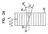
図2A,図2Bおよび図2Cは,この発明の実施形態による,AOD28の異なる3つの動作モード(three different modes of operation)を示す概略図である。最初の2つのモードは,上記例示したAA Optoelectronic社製AODのようなAODによって実現することができる。全てのモードにおいて,入射レーザ・ビーム,AOD内を進行する音響波の方向,および上記音響波によって生成される一または複数のサブ・ビームは,単一面内に存在する。
2A, 2B and 2C are schematic diagrams illustrating three different modes of operation of the
図2Aに示す第1のモードにおいて,処理ユニット36は振幅A1かつ周波数F1のRF信号を生成する。上記RF信号は音響波(弾性液)(acoustic wave)を構成し,この音響波によってAOD28は単一ピッチを有する回折格子として機能する。上記格子はレンズ26(図1)からの入射レーザ・ビーム24を角度α1だけ偏向し,単一のサブ・ビーム29を形成する。処理ユニット36は周波数F1の値を変化させることによって角度α1を変更することができる。また,上記サブ・ビーム中のパルス(複数)のエネルギーは振幅A1を変化させることによって変更することができる。
In the first mode shown in FIG. 2A, the
第1のモードにおいて,AODは,通常,最大でおよそ90%のビーム伝達効率(η)のもとで動作し,したがってA1の値を変化させることによって上記単一サブ・ビームのパルス(複数)のエネルギーはE=ηEtとなる。ここでEtはビーム24のパルス・エネルギー(the pulse energy)であり,η≦0.9である。残りのエネルギーは無偏向パルス・エネルギー(undeflected pulse energy)および低効率の高調波(low efficiency higher harmonics)である。上記無偏向パルス・エネルギーは,通常,ビーム・ダンプ(beam dump)によって吸収される。上記単一サブ・ビームのパルス(複数)の繰返速度はビーム24のパルス(複数)の繰返速度と同じであり,上記サブ・ビームの平均パワーはηPとなる。ここでPはビーム24の平均パワーである。
In the first mode, the AOD typically operates under a beam transfer efficiency (η) of up to approximately 90%, so the single sub-beam pulse (s) by changing the value of A1. The energy of E = ηEt. Here, Et is the pulse energy of the
図2Bに示す第2のモードにおいて,処理ユニット36は2以上の異なる周波数F1,F2,・・・を有する結合RF信号(combined RF signal)を生成する。第2の動作モードについては,D. L. Hechtの論文“Multifrequency acoustooptic deffraction”,IEEE Trans. Sonics Ultrasonics SU-24(1),7-18(1977)に記載されている。
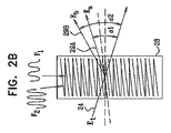
In the second mode shown in FIG. 2B, the
簡単にするために,図2Bにおいて,異なる2つの周波数の影響(効果)(effects)のみが示されている。処理ユニット36は,それぞれの振幅がA1,A2,・・・である各周波数(each of the frequencies)を生成する。処理ユニット36がRF信号の異なる周波数を生成することによって,AOD28はマルチ・ピッチの回折格子(multi-pitched diffraction grating)として効果的に機能し,上記RF入力によって音響波がAOD内を進行する。この場合,入射レーザ・ビーム24は異なる周波数F1,F2,・・・の数に対応する多数のサブ・ビーム29A,29B,・・・に分割される。サブ・ビーム群のそれぞれのサブ・ビームの角度α1,α2,・・・はそれぞれ周波数F1,F2,・・・によって定まる。
For simplicity, only the effects of two different frequencies are shown in FIG. 2B. The
各サブ・ビームのパルス(複数)のエネルギーEa,EbはEa=ηaEtおよびEb=ηbEtと表すことができる(ηa<1,ηb<1)。典型的には,上記AODの特性によって出射ビームの全パルス・エネルギー(the total pulse energy of the exiting beams)を約70%以下とすることができ,したがってここではEa+Eb≦0.7Etとなる。この全体的な制約の範囲内において,処理ユニット36は,各RF周波数の振幅値,ここではA1およびA2を変化させることによって,上記サブ・ビームのそれぞれのパルス・エネルギーを変更することができる。第1のモードと同様に,任意の無偏向エネルギーはビーム・ダンプによって吸収させることができる。出射サブ・ビーム(複数)のパルス繰返速度は入射ビームのパルス繰返速度と同じであり,入射ビームの平均パワーがPであれば,各サブ・ビームの平均パワーはPa=ηaPおよびPb=ηbPで与えられる。
The energy Ea, Eb of the pulses (plurality) of each sub beam can be expressed as Ea = ηaEt and Eb = ηbEt (ηa <1, ηb <1). Typically, due to the AOD characteristics, the total pulse energy of the exiting beam can be about 70% or less, so here Ea + Eb ≦ 0.7 Et. Within this overall constraint, the
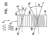
図2Cに示す第3のモードにおいて,処理ユニット36は,ピッチが異なる2以上の格子となるようにAOD28を効果的に分割するRF信号を生成する。この第3のモードを実現するためには,例示したAODのような「市販」の音響光学偏向器において通常利用可能な値から,AODの動作範囲(the operating window)が拡張される必要がある。上記拡張によって,AOD内に,「隣接」形態で(in a “side-by-side” manner)異なる格子(different gratings)を形成することができる。当業者であれば,必要以上の実験を行うことなく,上記拡張の量(the amount of the extension)および上記拡張を得るための要件(the requirements for producing the extension)を定めることができよう。
In the third mode shown in FIG. 2C, the
簡単にするために,第3のモードに関する以下の説明では,AOD28が2つの格子となるように効果的に分割されるものとする。第3のモードのためのRF信号は,それぞれの振幅がA1,A2である2つの周波数成分F1およびF2を有する。上記第2のモードのRF入力とは異なり,第3のモードのためのRF入力は,第2のモードのように周波数成分を組合わせるのではなく,異なる周波数成分が交互に切替わる。
For simplicity, in the following description of the third mode, it is assumed that
第3のモードにおいて,AOD28の前段のビーム・スプリッタ(図2Cにおいて図示略)が入射ビーム24を2つのビーム24Aおよび24Bに分割する。上記ビーム・スプリッタは典型的には光学ビーム・スプリッタであり,50:50といった任意の好適な分割比率を有することができる。これに代えて,典型的には上述した第2のモードにおいて動作するように構成された別のAODをビームスプリッタとして使用してもよい。ビーム24がパルス・エネルギーEtを有する場合,ビーム24Aおよび24Bはそれぞれパルス・エネルギーaEtおよびbEtを有する。ここで,aおよびbはa,b<1を満たし,かつa,bの値は上記ビーム・スプリッタに固有のものである。
In the third mode, a beam splitter (not shown in FIG. 2C) before the
各ビーム24A,24Bは,第1のモードに関して上述した通り,異なる格子(a different grating)によってそれぞれのピッチにしたがって偏向される。第3の動作モードによって結果的に生成されるサブ・ビーム29Cおよび29Dは,それぞれEc=aηaEtおよびEd=bηbEt(ηa<1,ηb<1)で与えられるパルス・エネルギーEcおよびEdを有する。第1のモードと同様に,ηaおよびηbの値は,それぞれA1およびA2の値を変化させることによって変更することができ,典型的には最大約0.9の値を有する。また,入射平均ビームパワーがPであるときに,上記サブ・ビームの平均パワーはPc=aηaPおよびPd=bηbPで与えられる。
Each
さらに,第1および第2のモードと同様に,第3のモードにおける任意の無偏向エネルギーはビーム・ダンプによって吸収させることができる。 Furthermore, as in the first and second modes, any unpolarized energy in the third mode can be absorbed by the beam dump.
AOD28の上記3つの動作モードの説明において,AOD28からのサブ・ビーム出力は,入射ビーム24と同じパルス繰返速度,すなわち同じ周波数を有する。しかしながら,このことは必要条件ではなく,この発明の一実施形態においては,上記サブ・ビーム出力の周波数が入力周波数の約数(a sub-multiple of the input frequency)となるように,処理ユニット36がAODへの上記RF入力を調整する。たとえば,図2Aに示すシステムにおいて,処理ユニット36が,ビーム24のパルス繰返速度にしたがって,AOD28への入力周波数をF1とF2との間で交互に切替えるようにしてもよい。これによって,ビーム24からのパルスの分散が角度α1とα2間で切替えられ,上記サブ・ビームのそれぞれにおけるパルス出力の周波数がビーム24のパルス周波数の半分となる。
In the description of the above three modes of operation of
ここで,上記パルス・エネルギー(複数)は入射パルス・エネルギー(複数)とほぼ同じであってもよい。しかしながら,上記サブ・ビーム(複数)におけるパルス(複数)の繰返速度が低下することに起因して,上記平均サブ・ビーム・パワーが上記平均入射ビーム・パワーから大幅に相違することになる。たとえば,上記入射ビームがパルス・エネルギーEtおよび平均パワーPを有し,各サブ・ビームのパルス(複数)が等しいエネルギーηEtを有するようにA1およびA2の値が設定されている場合,パルスの繰返率が半分になることに起因して,上記サブ・ビーム(複数)の平均パワーはηP/2となる。 Here, the pulse energy (s) may be substantially the same as the incident pulse energy (s). However, the average sub-beam power is significantly different from the average incident beam power due to a decrease in the repetition rate of the pulses in the sub-beams. For example, if the values of A1 and A2 are set such that the incident beam has a pulse energy Et and an average power P and the pulses of each sub-beam have equal energy ηEt, the repetition of the pulses Due to the half return factor, the average power of the sub-beams is ηP / 2.
上記サブ・ビーム(複数)のパルス繰返速度を上記入射ビームのパルス繰返速度の約数に設定できるようにすることによって,特定材料の穿孔にさらなる柔軟性がもたらされる。上記パルス・エネルギーは,典型的には,上記材料に最も影響を及ぼすパラメータであるので,上記に例示したように,上記パルス・エネルギーを入射ビームとほぼ同等に保ちつつ上記サブ・ビームの平均パワーを低減すると,材料の穿孔時に都合が良い。たとえば,上記平均パワーを低くすることでパルス間の冷却時間が伸ばされる(reducing the average power provides extra cooling time between pulses)。 By allowing the pulse repetition rate of the sub-beam (s) to be set to a divisor of the pulse repetition rate of the incident beam, additional flexibility is provided in drilling certain materials. Since the pulse energy is typically the parameter that has the most influence on the material, as illustrated above, the average power of the sub-beam is maintained while maintaining the pulse energy substantially equal to the incident beam. It is convenient when drilling material. For example, reducing the average power extends the cooling time between pulses (reducing the average power provides extra cooling time between pulses).
上述の種々サブ・ビームに加えて,処理ユニット36は,AODへの上記RF入力のパラメータを調整して各パルスのエネルギーを効果的に設定することにより,任意の特定サブ・ビームの全体的なエネルギー・プロファイルを時間的に(over time)適合させる(tailor)ことができる。たとえば,上記第1のモードにおいて,処理ユニットは,A1の急激な変化によってサブ・ビーム・パルス(複数)のエネルギーを急激に変化させるのではなく,多数のパルスにわたって上記エネルギーが線形的に減少するように構成してもよい。このような勾配を持つ線形的な減少(a ramped linear decrease)は,基板層から銅などの金属が意に反して除去されることを防止するために用いることができる。
In addition to the various sub-beams described above, the
AOD28の動作に関する上記説明を考慮すると,任意の特定時間に同時利用されるレーザ・サブ・ビーム29の数を処理ユニット36によって変更可能なシステムが,装置20によって提供されることが分かる。さらに,処理ユニット36は,各サブ・ビーム29におけるパルス・エネルギーの割合(比率)(fraction)を選択することができ,全体的なエネルギー・プロファイルを各サブ・ビームの時間で調整することができ,かつ各サブ・ビーム29のパルス周波数を入射ビーム24と同じ周波数またはその約数に設定することができる。
In view of the above description regarding the operation of the
以下の説明では,サブ・ビームの数,各サブ・ビームにおけるパルス・エネルギー,およびサブ・ビームの特性を装置20において種々変更することによって,異なる基板を効果的に穿孔する方法を示した様々な例を提供する。以下に示すように,ビーム数,パルス・エネルギーおよびビーム特性を種々変更することによって,異なる基板を穿孔するのに要する時間を最小化することができる。以下の説明では,処理ユニット36は,最大サブ・ビーム・パルス・エネルギーEmを有する任意の単一サブ・ビームと,Em未満のパルス・エネルギーを有する複数のサブ・ビームとが,処理ユニット36によって生成できるものとする。
In the following description, various methods have been shown that effectively drill different substrates by varying the number of sub-beams, the pulse energy in each sub-beam, and the characteristics of the sub-beams in apparatus 20. Provide an example. As shown below, the time required to drill different substrates can be minimized by varying the number of beams, pulse energy and beam characteristics. In the following description, the
また,以下の説明では3層基板を一例として用いるが,当然に,必要に応じて変更を加えることによって,2層またはその他任意の層数を有する基板への穿孔または加工に適用することもできる。 Further, in the following description, a three-layer substrate is used as an example, but it can be applied to drilling or processing a substrate having two layers or any other number of layers by changing as necessary. .
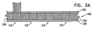
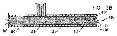
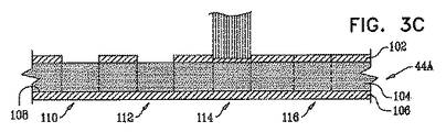
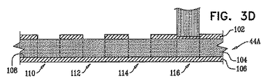
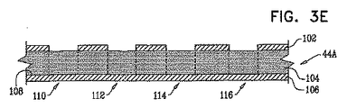
図3A〜図3Iは,この発明の実施形態による,基板44Aの穿孔過程における(in a time progression of drilling)様々な段階の概略図である。図3A〜図3Iは基板44Aの概略断面であり,図3Aが最初の段階に対応し,図3Iが最後の段階に対応している。上記基板は,穿孔が比較的困難な上側第1レイヤ102,穿孔が容易な第2レイヤ104,および穿孔されない第3レイヤ106を有するものとする。また,実質的に同様の,すなわち同一直径を有する4つの孔110,112,114および116が上記基板に穿孔されるものとする。ただし,2つの孔114および116は,第1プロセスにおいて仕上げられる上記2つの孔の下側境界(the lower bound)を,レイヤ104の上面108に有するものとする。その他2つの孔110および112については,相違する第2プロセスにおいて仕上げられる下側境界を有するものとする。
3A-3I are schematic diagrams of various stages in a time progression of drilling of a
一例として,4つの孔110,112,114および116は,ミラー38A,38B,38Cおよび38Dのそれぞれで反射された4つの分離した(独立の)(separate)サブ・ビーム41A,41B,41Cおよび41Dによって穿孔されるものとする。上述したように,サブ・ビーム41A,41B,41Cおよび41Dは,それぞれサブ・ビーム29A,29B,29Cおよび29Dから形成される。
As an example, the four
レイヤ102は穿孔が困難であるので,処理ユニット36はまず,一度に1つのサブ・ビームを用いて(using one sub-beam at a time)レイヤ102を穿孔する。各サブ・ビームは,パルス・エネルギーEmを有する。たとえば,各サブ・ビームはAOD28を第1のモード(図2A参照)で動作させて,異なる周波数F1,F2,F3およびF4を順次AODに供給することによって生成されるものとする。異なる周波数によって,サブ・ビーム29A,29B,29C,そして29Dが順次生成され,それぞれサブ・ビーム41A,41B,41C,および41Dを形成する。処理ユニット36は,ミラー38A,38B,38Cおよび38Dにおいてそれぞれ反射されたサブ・ビーム41A,41B,41Cおよび41Dを順次照射して,レイヤ102における孔110,112,114および116の各部位を穿孔する。図3Aに示すように,孔110の位置のレイヤ102が最初に穿孔される。その後,図3B,図3Cおよび図3Dに示すように,孔112,114および116の位置のレイヤ102が順次穿孔される。パルス・エネルギーEmのサブ・ビームがそれぞれ用いられる。図3Eはレイヤ102に4つの孔が全て穿孔された後の基板44Aの状態を示している。
Since
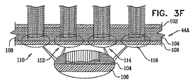
レイヤ104は穿孔が容易であり,かつ4つの孔全てに対して穿孔のためのアクセスが可能となっているので,処理ユニット36は,図3Fに示すように,レイヤ102の穿孔時と同じ4つのサブ・ビーム41A,41B,41Cおよび41Dを同時に動作させる。これらの4つのサブ・ビームは,利用可能なトータル・サブ・ビーム・エネルギーEavailableを実質的に等しい割合(比率)1/4Eavailableで使用するものとする。これら4つのサブ・ビームは,処理ユニットによってAOD28を第2のモード(図2B参照)において動作させ,それぞれが振幅A1,A2,A3およびA4を有する各周波数の結合周波数F1,F2,F3およびF4を有するRF入力をAODに与えることによって同時に形成される。
Since
振幅A1,A2,A3,およびA4は,各サブ・ビームのパルス・エネルギーがほぼ同等となるように選択されるが,上記第2のモードは上述の第1のモードと異なる特性を有するので,Eavailableが典型的にはEm未満となることが分かる。上記4つのサブ・ビームがミラー38A,38B,38Cおよび38Dを用いてレイヤ104を穿孔し,これら4つのサブ・ビームを用いた穿孔は,必要とされる適切な深さを有するレイヤ104の孔の穿孔が4本のサブ・ビーム全てについて完了するまで継続される。
The amplitudes A1, A2, A3, and A4 are selected so that the pulse energies of the sub-beams are substantially equal, but the second mode has different characteristics from the first mode described above. It can be seen that E available is typically less than Em. The four sub-beams pierce the
図3Gに示す次の穿孔段階において,処理ユニット36は,AOD28を第2または第3のモードで動作させることによって,孔114および116に対して,1/4Eavailableよりも大きな,ほぼ割合(比率)の等しいパルス・エネルギー(approximately equal fractional pulse energies)Efを持つサブ・ビーム41Cおよび41Dを動作させる。孔114および116の穿孔は孔が上面108に到達するまで継続される。一例では,この時点で,孔114および116の穿孔に最終仕上げが施される。この仕上げは,一例として,2つのサブ・ビームのエネルギーをEfから0まで低下させることによって施されるものとする。孔114および116に対する2つのサブ・ビームのエネルギーが低下するとき,処理ユニット36は,孔110および112に対するサブ・ビーム41Aおよび41Bのパルス・エネルギーを0からEfまで上昇させて,孔110および112の穿孔を開始してもよい。エネルギーの低下および上昇は,上述の通り,処理ユニットによって適当なRF入力をAOD28に与えることによって実現される。
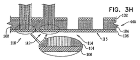
In the next drilling step shown in FIG. 3G, the
図3Hに示すように,処理ユニットは,上面108に到達するまで,パルス・エネルギーEfを用いた孔110および112の穿孔を継続する。一例では,処理ユニット36は,上面108の必要に応じた仕上げが完了するまで,上記パルス・エネルギーをEfに維持するものとする。仕上げが完了したとき,処理ユニットは孔110および112の穿孔を終了する。完成した孔を図3Iに示す。
As shown in FIG. 3H, the processing unit continues drilling holes 110 and 112 using pulse energy Ef until the
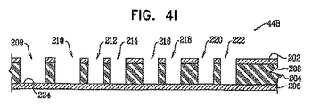
図4A〜図4Iは,この発明の実施形態による,基板44Bの穿孔過程における様々な段階を示す概略図である。図4A〜図4Iは基板44Bの概略断面であり,図4Aが最初の段階に対応し,図4Iが最後の段階に対応する。
4A-4I are schematic diagrams illustrating various stages in the drilling process of a
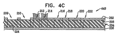
基板44Bは,穿孔が比較的困難な上側第1レイヤ202,穿孔が容易な第2レイヤ204,および穿孔されない第3レイヤ206を有するものとする。また,8つの孔209,210,212,214,216,218,220および222が上記基板に穿孔されるものとする。一例として,孔212,214,216,218,220および222が同一の直径D1を有し,孔209および210がD1よりも大きな同一直径D2を有するものとする。
The
一例において,8つの孔209,210,212,214,216,218,220および222は,ミラー38A,38B,38C,38D,38E,38F,38Gおよび38Hでそれぞれ反射された8つの分離した(独立の)サブ・ビーム41A,41B,41C,41D,41E,41F,41Gおよび41Hによって穿孔されるものとする。また,サブ・ビーム41A,・・・,41Hはそれぞれサブ・ビーム29A,・・・,29Hから形成される。
In one example, the eight
図4Aに示すように,処理ユニット36はまず,ミラー38Aによって方向が合わせられる,パルス・エネルギーE1および直径D2を持つサブ・ビーム41Aを用いて,孔209を穿孔する。レイヤ202の穿孔はレイヤ204の上面208に到達するまで継続され,そこに到達すると処理ユニットは孔209の穿孔を停止する。
As shown in FIG. 4A, the
図4Bに示すように,処理ユニット36は次に,ミラー38Bによって方向が合わせられる,パルス・エネルギーE1および直径D2を有するサブ・ビーム41Bを用いて孔210を穿孔する。この穿孔は上面208に到達するまで継続され,そこに到達すると,処理ユニットは孔210の穿孔を停止し,かつ孔212および214の穿孔を開始する。
As shown in FIG. 4B, processing
孔212および214は直径が小さいので,図4Cに示すように,処理ユニット36はこれらの両孔を同時に穿孔する。両孔を穿孔するために,処理ユニットは同じパルス・エネルギーE2および直径D1を有する2つのサブ・ビーム41Cおよび41Dを生成する。ここで,E2は,E1のある割合(一部)(a fraction)である。ユニット36は2つのミラー38Cおよび38Dを用いてこれらサブ・ビームを各孔に向ける。また,処理ユニットは,典型的にはAOD28の第2の動作モードを用いて2つのサブ・ビームを生成するので,これらサブ・ビームのパルス繰返速度はビーム24のパルス繰返速度と等しい。
Since the
あるいは,上記2つのサブ・ビームを,AOD28に関して上述した一または複数の他の方法によって生成してもよい。たとえば,処理ユニットはAOD28を第1のモードで動作させて,2つの異なる入力周波数を切替えることもできる。この場合,2つのサブ・ビーム41Cおよび41Dは同じパルス・エネルギーを有するが,パルス繰返速度はビーム24のパルス繰返速度の1/2となる。
Alternatively, the two sub-beams may be generated by one or more other methods described above with respect to
孔212および214の穿孔は各孔が上面208に到達するまで継続される。
Drilling of
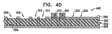
図4Dに示すように,孔212および214が上面208に到達すると,処理ユニットは穿孔を停止しかつ孔216および218の穿孔を開始する。孔216および218を穿孔するために,処理ユニット36は2つのサブ・ビーム41Eおよび41Fを生成し,2つのミラー38Eおよび38Fを用いてこれらのサブ・ビームを方向を合わせる。これらのサブ・ビームの生成方法は,典型的にはサブ・ビーム41C,41Dに関して上述した通りである。孔216および218の穿孔は,各孔が上面208に到達するまで継続される。
As shown in FIG. 4D, when
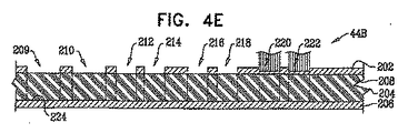
図4Eに示すように,孔216および218が上面208に到達すると,処理ユニットは穿孔を停止し,孔220および222の穿孔を開始する。孔220および222を穿孔するために,処理ユニット36は2本のサブ・ビーム41Gおよび41Hを生成し,2つのミラー38Gおよび38Hを用いてこれらのサブ・ビームの方向を合わせる。これらのサブ・ビームの生成方法は,典型的にはサブ・ビーム41C,41Dに関して上述した通りである。孔220および222の穿孔は,各孔が上面208に到達するまで継続される。
As shown in FIG. 4E, when
この時点で,基板44Bのレイヤ202における8つの孔の全て穿孔が完了する。
At this point, all eight holes in
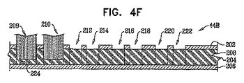
図4Fに示すように,処理ユニットは次に,レイヤ204に対する孔209および210の穿孔を開始する。レイヤ204はレイヤ202よりも穿孔が容易であるので,処理ユニット36は,2つのサブ・ビーム41Aおよび41Bを使用して,これら2つのサブ・ビームがE1よりも小さいほぼ同等のパルス・エネルギーを有するように設定する。処理ユニットは,レイヤ206の上面224に到達するまで孔209および210の穿孔を継続し,そこに到達するとサブ・ビーム41Aおよび41Bをオフする。
As shown in FIG. 4F, the processing unit then begins drilling holes 209 and 210 for
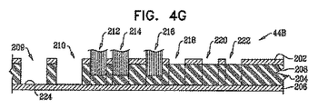
図4Gに示すように孔209および210が完成したら,処理ユニット36は,必要に応じて,典型的には基板44Bの他の領域をその後に穿孔するために,ミラー38Aおよび/または39Bの向きを再び合わせる(reorient)ことができる。
Once the
レイヤ204はレイヤ202よりも穿孔が容易である。このため,処理ユニット36は,典型的には孔212,214,216,218,220および222を,2つずつ3回に分けて穿孔するのではなく,3つずつ2回に分けて穿孔する。
図4Gに示すように,処理ユニット36はまず,孔212,214および216を穿孔する。処理ユニットは,これらの孔を穿孔するために,実質的には上述の通りで3つのサブ・ビーム41C,41Dおよび41Eを生成するが,これらのサブ・ビームのそれぞれは,E2のある割合(一部)(a fraction)である,同一のパルス・エネルギーE3を有する。あるいは,これら3つのサブ・ビームを,たとえば3つの異なる入力周波数の間で切替えるようにして,AOD28に関して上述した一または複数のその他の方法によって生成してもよい。この場合,3つのサブ・ビーム41C,41Dおよび41EはE1とほぼ同等のパルス・エネルギーを有するが,パルス繰返速度はビーム24のパルス繰返速度の1/3となる。
As shown in FIG. 4G, the
孔212,214および216の穿孔が完了すると,必要に応じて,処理ユニット36は基板44Bのその他の領域を穿孔するために,ミラー38C,38Dおよび/または38Eの向きを合わせることができる。
Once the
図4Hに示すように,処理ユニット36はその後,レイヤ202の穿孔に用いたサブ・ビームのパラメータを適宜変更したサブ・ビーム41F,41Gおよび41Hを用いて,図4Gを参照して上述したプロセスとほぼ同様にして,孔218,220および222を穿孔する。これらの孔の穿孔が完了すると,処理ユニット36は,基板の他の領域をその後に穿孔するために,必要に応じてミラー38F,28Gおよび/または38Hの向きを合わせることができる。
As shown in FIG. 4H, the
図4Iは全ての孔が穿孔された基板44Bの最終状態を示している。
FIG. 4I shows the final state of the
図5は,この発明の実施形態による,基板44を穿孔するために処理ユニット36において実行されるステップを示すフローチャート250である。このフローチャートの各ステップは,図3A〜図3Iおよび図4A〜図4Iを参照して上述した,複数孔の穿孔工程に対応している。
FIG. 5 is a
ビーム生成ステップ252において,処理ユニット36は,図1を参照して説明したように,レーザ22を動作させて,ビームのパルス(複数)のトータル・エネルギーがEtJである単一の出力ビーム24を生成する。通常,パルス繰返速度は一定である。
In the
ビーム分割ステップ254において,処理ユニット36は,RF入力をAOD28に供給することによって上記単一ビームを2つ以上のサブ・ビームに分割する。この単一ビームの分割は,図3Fおよび図4Cを参照して上記例示した通りである。上述のように,この分割によって,上記サブ・ビームのパルス・エネルギーを,ビーム24のトータル・エネルギーEtのある割合(比率,一部)(a fraction)とすることができる。
In
第1の穿孔ステップ256において,処理ユニット36は,図3Fおよび図4Cを参照して上述した通り,上記サブ・ビーム(複数)が複数孔のそれぞれの一部を同時に穿孔するように,上記サブ・ビーム(複数)を反射するミラー(複数)の向きを合わせる。
In a first drilling step 256, the
サブ・ビーム調整ステップ258において,処理ユニットは,上記サブ・ビーム(複数)の少なくとも1つのビームがステップ254のパルス・エネルギーと異なる割合のパルス・エネルギー(different fractional energy)を有するように,上記サブ・ビーム(複数)を調整(変更)する。
In
第2の穿孔ステップ260において,ユニット36は,調整された一または複数またはサブ・ビームを供給して各孔の穿孔を継続する。上記サブ・ビームの調整は,たとえば図3Gおよび図4Gを参照して説明した上記例示の通りである。
In the
典型的には,処理ユニット36は,必要に応じてフローチャート250のすべてまたは一部のステップを繰返すことにより,特定基板の全ての孔を穿孔する。
Typically, the
当然のことながら,上述の実施形態は一例として挙げたものであって,この発明は,上記図示および説明した内容には何ら限定されない。むしろ,この発明の範囲には,上述した様々な特徴のコンビネーションおよびサブ・コンビネーション,ならびに上記説明の解釈によって当業者が想到し得る,従来技術に開示されていない変形例および改良例が含まれる。 As a matter of course, the above-described embodiment is given as an example, and the present invention is not limited to the contents shown and described above. Rather, the scope of the present invention includes combinations and sub-combinations of the various features described above, as well as variations and improvements not disclosed in the prior art that may occur to those skilled in the art upon interpretation of the above description.
Claims (8)
上記単一出力ビームを時間経過の中で複数のビームに分割し,
上記複数のビームを多層基板上の複数の孔位置に当てる,
種々同時性をもって多層基板に複数の孔をレーザ穿孔する方法であって,
上記多層基板の複数層のそれぞれを穿孔するために実際に必要とされるエネルギー量に応じて,上記単一出力ビームから形成される複数のビームの数を制御して同時穿孔される複数孔の数を制御し,
同時穿孔される上記複数孔の数の関数である上記トータル・エネルギーの第1の割合を占めるパルス・エネルギーを有する上記複数のビームのうちの対応する複数のビームを用いて,少なくとも2つの複数孔の一の層を同時穿孔し,
その後,上記第1の割合と異なる,上記トータル・エネルギーの少なくとも第2の割合を占めるパルス・エネルギーをそれぞれが有する上記複数のビームのうちの少なくとも1つのビームを用いて,上記複数孔のうちの少なくとも1つの孔について少なくとも1つの追加層を穿孔する,
方法。 Operate the laser to produce a single output beam with a beam pulse with a total energy,
Split the single output beam into multiple beams over time,
The multiple beams are applied to multiple hole locations on the multilayer substrate.
A method of laser drilling a plurality of holes in a multilayer substrate with various simultaneity,
According to the amount of energy actually required to drill each of the plurality of layers of the multilayer substrate, the number of the plurality of holes to be simultaneously drilled is controlled by controlling the number of the plurality of beams formed from the single output beam. Control the number,
At least two multi-holes using corresponding ones of the plurality of beams having a pulse energy that occupies a first percentage of the total energy that is a function of the number of the plurality of holes to be simultaneously drilled. Simultaneously drilling one layer of
Then, using at least one of the plurality of beams each having a pulse energy that is different from the first ratio and occupies at least a second ratio of the total energy, Drilling at least one additional layer for at least one hole,
Method.
上記単一出力ビームを時間経過の中で複数のビームに分割し,
上記複数のビームを多層基板上の複数の孔位置に当てる,
種々同時性をもって多層基板に複数の孔をレーザ穿孔する方法であって,
上記多層基板の複数層のそれぞれを穿孔するために実際に必要とされるエネルギー量に応じて,上記単一出力ビームから形成される複数のビームの数を制御して同時穿孔される複数孔の数を制御し,
同時穿孔される上記複数孔の数の関数である上記トータル・パワーの第1の割合を占めるビーム・パワーを有する上記複数のビームのうちの対応する複数のビームを用いて,少なくとも2つの複数孔の一の層を同時穿孔し,
その後,上記第1の割合と異なる,上記トータル・パワーの少なくとも第2の割合を占めるビーム・パワーをそれぞれが有する上記複数のビームのうちの少なくとも1つのビームを用いて,上記複数孔のうちの少なくとも1つの孔について少なくとも1つの追加層を穿孔する,
方法。 Operating the laser to produce a single output beam with a certain total power,
Split the single output beam into multiple beams over time,
The multiple beams are applied to multiple hole locations on the multilayer substrate.
A method of laser drilling a plurality of holes in a multilayer substrate with various simultaneity,
According to the amount of energy actually required to drill each of the plurality of layers of the multilayer substrate , the number of the plurality of holes to be simultaneously drilled is controlled by controlling the number of the plurality of beams formed from the single output beam. Control the number,
At least two multi-holes using corresponding ones of the plurality of beams having a beam power that occupies a first percentage of the total power that is a function of the number of the plurality of holes to be simultaneously drilled. Simultaneously drilling one layer of
Then, using at least one of the plurality of beams each having a beam power that occupies at least a second ratio of the total power, which is different from the first ratio, Drilling at least one additional layer for at least one hole,
Method.
上記複数孔の上記一の層を穿孔する上記複数のビームのうちの対応する複数のビームが,上記パルス繰返速度の第1の割合を占めるパルス繰返速度と,上記単一ビーム・パルス・エネルギーの上記第1の割合を占めるパルス・エネルギーとを有する複数のパルスを含み,
上記複数孔のうちの少なくとも1つについて少なくとも1つの追加層を穿孔する上記複数のビームのうちの少なくとも1つのビームが,上記パルス繰返速度の第2の割合を占めるパルス繰返速度と,上記単一ビーム・パルス・エネルギーの上記第2の割合を占めるパルス・エネルギーとを有する複数のパルスを含む,
請求項3または4に記載の方法。 The single output beam comprises a plurality of pulses having a single beam pulse energy generated at a pulse repetition rate;
A plurality of corresponding beams of the plurality of holes perforating the one layer of the plurality of holes, wherein the corresponding beam occupies a first rate of the pulse repetition rate; and the single beam pulse pulse A plurality of pulses having pulse energy occupying said first proportion of energy;
A pulse repetition rate in which at least one of the plurality of beams drilling at least one additional layer for at least one of the plurality of holes occupies a second proportion of the pulse repetition rate; and A plurality of pulses having a pulse energy occupying the second fraction of the single beam pulse energy,
The method according to claim 3 or 4.
Applications Claiming Priority (3)
| Application Number | Priority Date | Filing Date | Title |
|---|---|---|---|
| US2027308P | 2008-01-10 | 2008-01-10 | |
| US61/020,273 | 2008-01-10 | ||
| PCT/IL2009/000042 WO2009087639A2 (en) | 2008-01-10 | 2009-01-11 | Multiple beam drilling system |
Publications (2)
| Publication Number | Publication Date |
|---|---|
| JP2011523373A JP2011523373A (en) | 2011-08-11 |
| JP5659020B2 true JP5659020B2 (en) | 2015-01-28 |
Family
ID=40853536
Family Applications (2)
| Application Number | Title | Priority Date | Filing Date |
|---|---|---|---|
| JP2010541887A Active JP5659020B2 (en) | 2008-01-10 | 2009-01-11 | Multiple beam drilling system |
| JP2010541886A Active JP5443390B2 (en) | 2008-01-10 | 2009-01-11 | Multi-mirror calibration system |
Family Applications After (1)
| Application Number | Title | Priority Date | Filing Date |
|---|---|---|---|
| JP2010541886A Active JP5443390B2 (en) | 2008-01-10 | 2009-01-11 | Multi-mirror calibration system |
Country Status (5)
| Country | Link |
|---|---|
| US (2) | US8395083B2 (en) |
| JP (2) | JP5659020B2 (en) |
| KR (2) | KR101540137B1 (en) |
| CN (2) | CN101910787B (en) |
| WO (2) | WO2009087639A2 (en) |
Families Citing this family (19)
| Publication number | Priority date | Publication date | Assignee | Title |
|---|---|---|---|---|
| CN103066479A (en) * | 2012-12-14 | 2013-04-24 | 青岛镭创光电技术有限公司 | Laser crystal assembly device and method |
| CN103394809A (en) * | 2013-08-06 | 2013-11-20 | 孙树峰 | Automobile oil sprayer minuteness oil spraying hole femtosecond laser efficient and precise machining device and method |
| US11536956B2 (en) | 2013-11-25 | 2022-12-27 | Preco, Llc | High density galvo housing for use with multiple laser beams |
| CN103658975B (en) * | 2013-12-03 | 2017-02-15 | 张立国 | Laser beam splitting and processing device |
| US10239155B1 (en) * | 2014-04-30 | 2019-03-26 | The Boeing Company | Multiple laser beam processing |
| US9269149B2 (en) | 2014-05-08 | 2016-02-23 | Orbotech Ltd. | Calibration of a direct-imaging system |
| US9925797B2 (en) | 2014-08-07 | 2018-03-27 | Orbotech Ltd. | Lift printing system |
| WO2016063270A1 (en) | 2014-10-19 | 2016-04-28 | Orbotech Ltd. | Llift printing of conductive traces onto a semiconductor substrate |
| KR102446523B1 (en) | 2014-11-12 | 2022-09-22 | 오르보테크 엘티디. | Acousto-optic deflector with multiple output beams |
| US10633758B2 (en) | 2015-01-19 | 2020-04-28 | Orbotech Ltd. | Printing of three-dimensional metal structures with a sacrificial support |
| US10471538B2 (en) * | 2015-07-09 | 2019-11-12 | Orbotech Ltd. | Control of lift ejection angle |
| WO2017085712A1 (en) | 2015-11-22 | 2017-05-26 | Orbotech Ltd | Control of surface properties of printed three-dimensional structures |
| PL3523083T3 (en) * | 2016-11-18 | 2024-02-05 | Ipg Photonics Corporation | System and method for laser processing of materials. |
| TW201901887A (en) | 2017-05-24 | 2019-01-01 | 以色列商奧寶科技股份有限公司 | Electrical interconnection circuit components on the substrate without prior patterning |
| US10330460B2 (en) | 2017-06-13 | 2019-06-25 | Raytheon Company | Calibration method and system for a fast steering mirror |
| CN107199408A (en) * | 2017-07-25 | 2017-09-26 | 英诺激光科技股份有限公司 | The method that cutting taper lifts cutting speed is reduced using multi beam ultrafast laser |
| CN107907876A (en) * | 2017-11-27 | 2018-04-13 | 合肥通彩自动化设备有限公司 | A kind of laser orientation system and method |
| EP3521483A1 (en) * | 2018-02-06 | 2019-08-07 | Nederlandse Organisatie voor toegepast- natuurwetenschappelijk onderzoek TNO | Lift deposition apparatus and method |
| CN120645561A (en) | 2019-05-07 | 2025-09-16 | 奥宝科技有限公司 | LIFT printing using thin Shi Tibo |
Family Cites Families (15)
| Publication number | Priority date | Publication date | Assignee | Title |
|---|---|---|---|---|
| US4270130A (en) * | 1979-01-08 | 1981-05-26 | Eastman Kodak Company | Thermal deformation record device with bleachable dye |
| US4822974A (en) * | 1988-02-18 | 1989-04-18 | United Technologies Corporation | Laser hold drilling system with lens and two wedge prisms including axial displacement of at least one prism |
| JP3691221B2 (en) * | 1997-09-24 | 2005-09-07 | 三菱電機株式会社 | Laser processing method |
| DE19831340C1 (en) * | 1998-07-13 | 2000-03-02 | Siemens Ag | Method and arrangement for calibrating a laser processing machine for processing workpieces |
| JP3553451B2 (en) * | 2000-02-18 | 2004-08-11 | 独立行政法人 科学技術振興機構 | Optical coherence tomographic observation system |
| US6433043B1 (en) | 2000-11-28 | 2002-08-13 | Transitions Optical, Inc. | Removable imbibition composition of photochromic compound and kinetic enhancing additive |
| CN1131122C (en) * | 2001-05-10 | 2003-12-17 | 中国科学技术大学 | Laser Holing device and two-step holing method |
| KR100938325B1 (en) * | 2001-06-13 | 2010-01-22 | 오르보테크 엘티디. | Multi-beam micro-machining system and method |
| US7065121B2 (en) * | 2001-07-24 | 2006-06-20 | Gsi Group Ltd. | Waveguide architecture, waveguide devices for laser processing and beam control, and laser processing applications |
| DE10145184B4 (en) * | 2001-09-13 | 2005-03-10 | Siemens Ag | Method for laser drilling, in particular using a shadow mask |
| KR100759544B1 (en) | 2001-09-24 | 2007-09-18 | 삼성에스디아이 주식회사 | Dual Dynamic Focus Gun |
| US6740847B1 (en) * | 2003-03-10 | 2004-05-25 | Siemens Vdo Automotive Corporation | Method of forming multiple machining spots by a single laser |
| US9022037B2 (en) * | 2003-08-11 | 2015-05-05 | Raydiance, Inc. | Laser ablation method and apparatus having a feedback loop and control unit |
| JP3872462B2 (en) * | 2003-09-01 | 2007-01-24 | 住友重機械工業株式会社 | Laser processing apparatus and laser processing method |
| US7521651B2 (en) * | 2003-09-12 | 2009-04-21 | Orbotech Ltd | Multiple beam micro-machining system and method |
-
2009
- 2009-01-11 WO PCT/IL2009/000042 patent/WO2009087639A2/en not_active Ceased
- 2009-01-11 JP JP2010541887A patent/JP5659020B2/en active Active
- 2009-01-11 US US12/812,073 patent/US8395083B2/en active Active
- 2009-01-11 KR KR1020107014374A patent/KR101540137B1/en active Active
- 2009-01-11 CN CN2009801017280A patent/CN101910787B/en active Active
- 2009-01-11 JP JP2010541886A patent/JP5443390B2/en active Active
- 2009-01-11 CN CN200980101729.5A patent/CN101909804B/en active Active
- 2009-01-11 WO PCT/IL2009/000041 patent/WO2009087638A2/en not_active Ceased
- 2009-01-11 KR KR1020107015335A patent/KR101528385B1/en active Active
- 2009-01-11 US US12/812,149 patent/US8390795B2/en active Active
Also Published As
| Publication number | Publication date |
|---|---|
| US20100282726A1 (en) | 2010-11-11 |
| WO2009087638A3 (en) | 2010-03-11 |
| WO2009087638A2 (en) | 2009-07-16 |
| US20100328643A1 (en) | 2010-12-30 |
| CN101909804B (en) | 2014-10-22 |
| JP2011523373A (en) | 2011-08-11 |
| CN101909804A (en) | 2010-12-08 |
| KR101540137B1 (en) | 2015-07-28 |
| WO2009087639A3 (en) | 2010-03-11 |
| JP5443390B2 (en) | 2014-03-19 |
| KR20100113068A (en) | 2010-10-20 |
| WO2009087639A2 (en) | 2009-07-16 |
| KR20100102654A (en) | 2010-09-24 |
| JP2011510817A (en) | 2011-04-07 |
| CN101910787A (en) | 2010-12-08 |
| CN101910787B (en) | 2013-03-13 |
| US8395083B2 (en) | 2013-03-12 |
| KR101528385B1 (en) | 2015-06-11 |
| US8390795B2 (en) | 2013-03-05 |
Similar Documents
| Publication | Publication Date | Title |
|---|---|---|
| JP5659020B2 (en) | Multiple beam drilling system | |
| US7176409B2 (en) | Multiple beam micromachining system for removing at least two different layers of a substrate | |
| DE102004043895A1 (en) | Multi-beam micro-machining system and method | |
| CN106067432B (en) | Method and apparatus for dicing wafers | |
| JP6025837B2 (en) | Method and apparatus for machining a workpiece, in particular for producing a cutting tool | |
| TW202105863A (en) | Laser processing apparatus, methods of operating the same, and methods of processing workpieces using the same | |
| EP2925481A2 (en) | Device and method for laser material machining | |
| CN1213997A (en) | Method for Forming Blind Channels in Multilayer Targets Using Ultraviolet Laser Pulses with Variable Power Density | |
| WO2010076547A1 (en) | Method and apparatus for forming grooves in the surface of a polymer layer | |
| DE112005001418T5 (en) | Semiconductor structure processing using multiple laser beam spots | |
| DE102009047995B3 (en) | Method for burr-free cutting of workpieces | |
| CN111730220B (en) | Laser processing apparatus and laser processing method | |
| DE112006001294T5 (en) | Synthetic pulse repetition rate for micro machining systems with double head laser | |
| TWI460040B (en) | Method for laser drilling of holes in a substrate with varying simultaneity | |
| EP4204179A1 (en) | Method for machining a material | |
| RU2492036C1 (en) | Method of punching micro holes by pulled laser radiation | |
| DE102024203187A1 (en) | Laser drilling process and laser drilling system |
Legal Events
| Date | Code | Title | Description |
|---|---|---|---|
| A621 | Written request for application examination |
Free format text: JAPANESE INTERMEDIATE CODE: A621 Effective date: 20111104 |
|
| A131 | Notification of reasons for refusal |
Free format text: JAPANESE INTERMEDIATE CODE: A131 Effective date: 20130319 |
|
| A977 | Report on retrieval |
Free format text: JAPANESE INTERMEDIATE CODE: A971007 Effective date: 20130322 |
|
| A601 | Written request for extension of time |
Free format text: JAPANESE INTERMEDIATE CODE: A601 Effective date: 20130619 |
|
| A602 | Written permission of extension of time |
Free format text: JAPANESE INTERMEDIATE CODE: A602 Effective date: 20130626 |
|
| A601 | Written request for extension of time |
Free format text: JAPANESE INTERMEDIATE CODE: A601 Effective date: 20130717 |
|
| A602 | Written permission of extension of time |
Free format text: JAPANESE INTERMEDIATE CODE: A602 Effective date: 20130724 |
|
| A601 | Written request for extension of time |
Free format text: JAPANESE INTERMEDIATE CODE: A601 Effective date: 20130819 |
|
| A602 | Written permission of extension of time |
Free format text: JAPANESE INTERMEDIATE CODE: A602 Effective date: 20130826 |
|
| A521 | Request for written amendment filed |
Free format text: JAPANESE INTERMEDIATE CODE: A523 Effective date: 20130918 |
|
| A131 | Notification of reasons for refusal |
Free format text: JAPANESE INTERMEDIATE CODE: A131 Effective date: 20140225 |
|
| A601 | Written request for extension of time |
Free format text: JAPANESE INTERMEDIATE CODE: A601 Effective date: 20140523 |
|
| A602 | Written permission of extension of time |
Free format text: JAPANESE INTERMEDIATE CODE: A602 Effective date: 20140530 |
|
| A601 | Written request for extension of time |
Free format text: JAPANESE INTERMEDIATE CODE: A601 Effective date: 20140624 |
|
| A602 | Written permission of extension of time |
Free format text: JAPANESE INTERMEDIATE CODE: A602 Effective date: 20140701 |
|
| A521 | Request for written amendment filed |
Free format text: JAPANESE INTERMEDIATE CODE: A523 Effective date: 20140711 |
|
| TRDD | Decision of grant or rejection written | ||
| A01 | Written decision to grant a patent or to grant a registration (utility model) |
Free format text: JAPANESE INTERMEDIATE CODE: A01 Effective date: 20141111 |
|
| A61 | First payment of annual fees (during grant procedure) |
Free format text: JAPANESE INTERMEDIATE CODE: A61 Effective date: 20141201 |
|
| R150 | Certificate of patent or registration of utility model |
Ref document number: 5659020 Country of ref document: JP Free format text: JAPANESE INTERMEDIATE CODE: R150 |
|
| R250 | Receipt of annual fees |
Free format text: JAPANESE INTERMEDIATE CODE: R250 |
|
| R250 | Receipt of annual fees |
Free format text: JAPANESE INTERMEDIATE CODE: R250 |
|
| R250 | Receipt of annual fees |
Free format text: JAPANESE INTERMEDIATE CODE: R250 |
|
| R250 | Receipt of annual fees |
Free format text: JAPANESE INTERMEDIATE CODE: R250 |
|
| R250 | Receipt of annual fees |
Free format text: JAPANESE INTERMEDIATE CODE: R250 |
|
| R250 | Receipt of annual fees |
Free format text: JAPANESE INTERMEDIATE CODE: R250 |
|
| R250 | Receipt of annual fees |
Free format text: JAPANESE INTERMEDIATE CODE: R250 |
|
| R250 | Receipt of annual fees |
Free format text: JAPANESE INTERMEDIATE CODE: R250 |
|
| R250 | Receipt of annual fees |
Free format text: JAPANESE INTERMEDIATE CODE: R250 |