JP5658577B2 - Hollow body forming equipment - Google Patents
Hollow body forming equipment Download PDFInfo
- Publication number
- JP5658577B2 JP5658577B2 JP2011016091A JP2011016091A JP5658577B2 JP 5658577 B2 JP5658577 B2 JP 5658577B2 JP 2011016091 A JP2011016091 A JP 2011016091A JP 2011016091 A JP2011016091 A JP 2011016091A JP 5658577 B2 JP5658577 B2 JP 5658577B2
- Authority
- JP
- Japan
- Prior art keywords
- floating core
- port
- mold
- pressure port
- cavity
- Prior art date
- Legal status (The legal status is an assumption and is not a legal conclusion. Google has not performed a legal analysis and makes no representation as to the accuracy of the status listed.)
- Active
Links
- 238000007667 floating Methods 0.000 claims description 121
- 229920005989 resin Polymers 0.000 claims description 57
- 239000011347 resin Substances 0.000 claims description 57
- 238000000465 moulding Methods 0.000 claims description 23
- 238000002347 injection Methods 0.000 claims description 19
- 239000007924 injection Substances 0.000 claims description 19
- 239000012530 fluid Substances 0.000 claims description 16
- 238000000034 method Methods 0.000 claims description 12
- NJPPVKZQTLUDBO-UHFFFAOYSA-N novaluron Chemical compound C1=C(Cl)C(OC(F)(F)C(OC(F)(F)F)F)=CC=C1NC(=O)NC(=O)C1=C(F)C=CC=C1F NJPPVKZQTLUDBO-UHFFFAOYSA-N 0.000 claims description 9
- 238000004891 communication Methods 0.000 description 11
- 239000007789 gas Substances 0.000 description 6
- 238000001746 injection moulding Methods 0.000 description 6
- 230000015572 biosynthetic process Effects 0.000 description 4
- 238000001816 cooling Methods 0.000 description 4
- IJGRMHOSHXDMSA-UHFFFAOYSA-N Atomic nitrogen Chemical compound N#N IJGRMHOSHXDMSA-UHFFFAOYSA-N 0.000 description 3
- 238000005520 cutting process Methods 0.000 description 3
- 229910001873 dinitrogen Inorganic materials 0.000 description 3
- 229910052751 metal Inorganic materials 0.000 description 3
- 239000002184 metal Substances 0.000 description 3
- 238000007493 shaping process Methods 0.000 description 3
- 238000004904 shortening Methods 0.000 description 3
- 229920005992 thermoplastic resin Polymers 0.000 description 3
- 229920001187 thermosetting polymer Polymers 0.000 description 3
- VTYYLEPIZMXCLO-UHFFFAOYSA-L Calcium carbonate Chemical compound [Ca+2].[O-]C([O-])=O VTYYLEPIZMXCLO-UHFFFAOYSA-L 0.000 description 2
- CURLTUGMZLYLDI-UHFFFAOYSA-N Carbon dioxide Chemical compound O=C=O CURLTUGMZLYLDI-UHFFFAOYSA-N 0.000 description 2
- PEDCQBHIVMGVHV-UHFFFAOYSA-N Glycerine Chemical compound OCC(O)CO PEDCQBHIVMGVHV-UHFFFAOYSA-N 0.000 description 2
- 238000000071 blow moulding Methods 0.000 description 2
- 238000004519 manufacturing process Methods 0.000 description 2
- -1 polypropylene Polymers 0.000 description 2
- 239000005995 Aluminium silicate Substances 0.000 description 1
- 241001465754 Metazoa Species 0.000 description 1
- 229920002292 Nylon 6 Polymers 0.000 description 1
- 229920002302 Nylon 6,6 Polymers 0.000 description 1
- 239000004698 Polyethylene Substances 0.000 description 1
- 239000004743 Polypropylene Substances 0.000 description 1
- 239000004793 Polystyrene Substances 0.000 description 1
- 239000003570 air Substances 0.000 description 1
- 235000012211 aluminium silicate Nutrition 0.000 description 1
- 238000005452 bending Methods 0.000 description 1
- 229910000019 calcium carbonate Inorganic materials 0.000 description 1
- 239000001569 carbon dioxide Substances 0.000 description 1
- 229910002092 carbon dioxide Inorganic materials 0.000 description 1
- 230000007423 decrease Effects 0.000 description 1
- 238000007599 discharging Methods 0.000 description 1
- 230000000694 effects Effects 0.000 description 1
- 239000003365 glass fiber Substances 0.000 description 1
- 235000011187 glycerol Nutrition 0.000 description 1
- 239000011261 inert gas Substances 0.000 description 1
- 239000011256 inorganic filler Substances 0.000 description 1
- 229910003475 inorganic filler Inorganic materials 0.000 description 1
- NLYAJNPCOHFWQQ-UHFFFAOYSA-N kaolin Chemical compound O.O.O=[Al]O[Si](=O)O[Si](=O)O[Al]=O NLYAJNPCOHFWQQ-UHFFFAOYSA-N 0.000 description 1
- 239000007788 liquid Substances 0.000 description 1
- 229940057995 liquid paraffin Drugs 0.000 description 1
- 239000000463 material Substances 0.000 description 1
- 239000005011 phenolic resin Substances 0.000 description 1
- 239000004033 plastic Substances 0.000 description 1
- 229920003023 plastic Polymers 0.000 description 1
- 229920003229 poly(methyl methacrylate) Polymers 0.000 description 1
- 229920006122 polyamide resin Polymers 0.000 description 1
- 239000004417 polycarbonate Substances 0.000 description 1
- 229920000515 polycarbonate Polymers 0.000 description 1
- 229920001225 polyester resin Polymers 0.000 description 1
- 239000004645 polyester resin Substances 0.000 description 1
- 229920000573 polyethylene Polymers 0.000 description 1
- 239000004926 polymethyl methacrylate Substances 0.000 description 1
- 229920005672 polyolefin resin Polymers 0.000 description 1
- 229920001155 polypropylene Polymers 0.000 description 1
- 229920002223 polystyrene Polymers 0.000 description 1
- 229920005990 polystyrene resin Polymers 0.000 description 1
- 239000004800 polyvinyl chloride Substances 0.000 description 1
- 229920000915 polyvinyl chloride Polymers 0.000 description 1
- 239000012779 reinforcing material Substances 0.000 description 1
- 238000010112 shell-mould casting Methods 0.000 description 1
- 229920003002 synthetic resin Polymers 0.000 description 1
- 239000000057 synthetic resin Substances 0.000 description 1
- 239000000454 talc Substances 0.000 description 1
- 229910052623 talc Inorganic materials 0.000 description 1
- 229920006337 unsaturated polyester resin Polymers 0.000 description 1
- XLYOFNOQVPJJNP-UHFFFAOYSA-N water Substances O XLYOFNOQVPJJNP-UHFFFAOYSA-N 0.000 description 1
- 238000003466 welding Methods 0.000 description 1
Images


Landscapes
- Injection Moulding Of Plastics Or The Like (AREA)
Description
本発明は、中空体成形装置に関する。 The present invention relates to a hollow body forming apparatus.
一般に、合成樹脂成形体に中空部を形成する方法としては、ブロー成形法が最も良く知られており、ボトルや容器、パイプ等の製造に幅広く用いられている。しかし、ブロー成形法はデザイン上の制限が多く、適応可能な材料の選択の幅が狭く、さらに寸法精度があまり良くない等の課題がある。 In general, the blow molding method is the best known method for forming a hollow portion in a synthetic resin molded body, and is widely used in the manufacture of bottles, containers, pipes and the like. However, the blow molding method has many design limitations, and there is a problem that the range of selection of applicable materials is narrow and the dimensional accuracy is not so good.
そこで近年、射出成形による中空体成形方法が種々提案されており、例えば、ロストコア法、2シェル成形溶着法、及びダイスライド射出成形法等が挙げられる(特許文献1)。しかしながら、これらの成形方法を用いて、曲管部を有する長尺の3次元屈曲パイプを製造するのは困難であった。 Therefore, various hollow body molding methods by injection molding have been proposed in recent years, and examples thereof include a lost core method, a two-shell molding welding method, and a die slide injection molding method (Patent Document 1). However, it has been difficult to produce a long three-dimensional bent pipe having a curved pipe portion using these molding methods.
かかる課題を解決すべく、近年、一端にフローティングコアを備えた加圧ポートを有し、他端に排出口を有する主キャビティ内に溶融樹脂を射出した後、加圧ポートから加圧流体を圧入してフローティングコアを排出口側に移動させると共に、排出口から溶融樹脂を押し出させて中空成形体を成形する中空体成形装置が提案されている(特許文献2)。この中空体成形装置では、成形の1サイクルごとに金型を開き、外部から加圧ポート上にフローティングコアが設置される。次いで、金型を閉じて樹脂を主キャビティ中に充填し、加圧ポートから圧入される加圧流体によって該フローティングコアが主キャビティ中に発射される。次いで、フローティングコアが排出口側に移動されると共に該排出口から余剰樹脂を副キャビティに押出すことにより、中空成形体が成形される。フローティングコアは予め作成され、人手またはハンドリングロボット等を用いて、金型の加圧ポート上にインサート装填される。 In order to solve this problem, in recent years, a molten resin is injected into a main cavity having a pressurized port with a floating core at one end and a discharge port at the other end, and then pressurized fluid is injected from the pressurized port. Thus, a hollow body forming apparatus that moves the floating core to the discharge port side and extrudes molten resin from the discharge port to form a hollow molded body has been proposed (Patent Document 2). In this hollow body molding apparatus, the mold is opened for each molding cycle, and a floating core is installed on the pressure port from the outside. Next, the mold is closed to fill the main cavity with resin, and the floating core is fired into the main cavity by the pressurized fluid that is press-fitted from the pressurized port. Next, the floating core is moved to the discharge port side, and excess resin is extruded from the discharge port to the sub-cavity, thereby forming a hollow molded body. The floating core is prepared in advance, and insert-loaded onto the pressurizing port of the mold using a manual or handling robot.
また、中空成形体の成形と共に、副キャビティでフローティングコアを同時に成形する方法が提案されている(特許文献3)。この成形方法によれば、フローティングコアが同時に成形されるので、予め別の金型でフローティングコアを作成する必要がなく、効率的である。 Further, a method has been proposed in which a floating core is simultaneously formed in a subcavity together with the formation of a hollow molded body (Patent Document 3). According to this molding method, since the floating core is molded at the same time, it is not necessary to prepare the floating core with another mold in advance, which is efficient.
ところで、特許文献3に記載の技術によれば、中空成形体の成形と共に、副キャビティでフローティングコアが同時に成形される。しかし、フローティングコアは一旦冷却固化された後に金型から取り出す工程と、取り出したコアを再度金型の加圧ポート上にインサート装填する工程とが必要であり、フローティングコアのハンドリングに人手を要していた。あるいは、ロボット等を用いてフローティングコアのハンドリングを行なうことも可能であるが、工程の煩雑化が避けられず、成形サイクルの効率化及び短縮化には限界があった。 By the way, according to the technique described in Patent Document 3, the floating core is simultaneously formed in the subcavity together with the formation of the hollow molded body. However, the floating core must be cooled and solidified and then removed from the mold, and the removed core is inserted into the pressurization port of the mold again, which requires manpower to handle the floating core. It was. Alternatively, it is possible to handle the floating core using a robot or the like, but the complexity of the process is inevitable, and there is a limit to the efficiency and shortening of the molding cycle.
そこで本発明は、上記の課題に鑑みてなされたもので、同一の金型内で中空成形体の成形と共にフローティングコアを同時に成形し、かつ成形したフローティングコアをそのまま次のショットに使用でき、成形サイクルの効率化及び短縮化を図ることができる中空体成形装置を提供することを目的とする。 Therefore, the present invention has been made in view of the above-described problems, and can form a floating core at the same time as forming a hollow molded body in the same mold, and the molded floating core can be used as it is for the next shot. It aims at providing the hollow body shaping | molding apparatus which can aim at the efficiency improvement and shortening of a cycle.
即ち、本発明の中空体成形装置は、一端にフローティングコアを備えた加圧ポートが配され、他端に排出口を有する主キャビティを備えた金型の該主キャビティ内に溶融樹脂を射出した後、前記加圧ポートから加圧流体を圧入して前記フローティングコアを排出口側に移動させると共に、前記排出口から溶融樹脂を押し出させて中空成形体を成形する中空体成形装置において、
前記金型は、前記主キャビティの加圧ポート側の周囲に前記フローティングコアを成形する複数のフローティングコアキャビティを有し、
前記金型に対して移動可能に加圧ポート台座が配設されると共に、該加圧ポート台座に複数の加圧ポートが配設され、
前記主キャビティ内で中空成形体を成形すると共に、前記フローティングコアキャビティのうち少なくとも一つに、待機中の加圧ポートを臨ませて該加圧ポート上にフローティングコアを成形し、
該成形されたフローティングコアが前記加圧ポート上に装着されたままの状態で、次のショットに際して前記主キャビティに臨むように、前記加圧ポート台座を移動させることを特徴とする。
That is, in the hollow body forming apparatus of the present invention, a molten resin is injected into the main cavity of a mold provided with a pressure port having a floating core at one end and a main cavity having a discharge port at the other end. After that, in the hollow body forming apparatus for pressurizing the pressurized fluid from the pressure port and moving the floating core to the discharge port side, and extruding the molten resin from the discharge port to form a hollow molded body,
The mold has a plurality of floating core cavities for molding the floating core around the pressure port side of the main cavity,
A pressure port pedestal is disposed so as to be movable with respect to the mold, and a plurality of pressure ports are disposed on the pressure port pedestal,
A hollow molded body is molded in the main cavity, and at least one of the floating core cavities faces a standby pressure port to mold a floating core on the pressure port,
The pressure port pedestal is moved so as to face the main cavity at the time of the next shot in a state where the molded floating core is mounted on the pressure port.
本発明によれば、同一金型内でパイプとフローティングコアとが同時に成形されると共に、フローティングコアは、金型内で次のショットの加圧ポート上に装着された状態で成形されるため、そのまま次のショットに使用できる。したがって、人手やハンドリングロボット等を用いず、成形サイクルの効率化及び短縮化を図ることができるという優れた効果を発揮する。 According to the present invention, the pipe and the floating core are simultaneously molded in the same mold, and the floating core is molded in a state of being mounted on the pressure port of the next shot in the mold. It can be used for the next shot as it is. Therefore, it is possible to achieve an excellent effect that the molding cycle can be made more efficient and shorter without using human hands or a handling robot.
以下、図面を参照して、本発明の実施の形態を説明するが、本発明はこれらの実施形態に限定されない。なお、本明細書で特に図示または記載されない部分に関しては、当該技術分野の周知または公知技術を適用する。 Hereinafter, embodiments of the present invention will be described with reference to the drawings, but the present invention is not limited to these embodiments. In addition, the well-known or well-known technique of the said technical field is applied regarding the part which is not illustrated or described in particular in this specification.
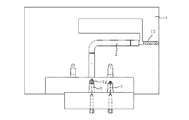
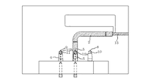
まず図1を参照して、本発明に係る中空体成形装置の一実施形態について説明する。図1は、本発明に係る中空体成形装置の一実施形態における金型の型開き状態を示す概略図である。 First, an embodiment of a hollow body forming apparatus according to the present invention will be described with reference to FIG. FIG. 1 is a schematic view showing a mold open state of a mold in an embodiment of a hollow body forming apparatus according to the present invention.
本実施形態の中空体成形装置の本体を構成する金型1は射出成形金型であり、溶融樹脂の射出ゲート3,10,11を有する固定型と、型開き時及び型組み時に移動する可動型とからなっている。図1に例示される金型1は型開き状態の固定型であり、パイプ等の中空成形体を成形する主キャビティ2、この主キャビティ2に連通された副キャビティ4、2基の加圧ポート5,6、及びフローティングコアを成形するフローティングコアキャビティ8,9を主に備えている。
The mold 1 constituting the main body of the hollow body molding apparatus of the present embodiment is an injection mold, and is a fixed mold having molten
主キャビティ2は、屈曲部(エルボ部)を有する中空成形体(パイプ)の外形に沿った成形空間を含むもので、その一端(基端)に、フローティングコアが装着される加圧ポート5,6が配される。本実施形態では、主キャビティ2は、加圧ポート5,6を挿入配置する空間を有し、その上に中空成形体(パイプ)の外形に沿った成形空間を有する。主キャビティ2の基端側の直管部には、この主キャビティ2の内部に溶融樹脂を射出する射出ゲート3が開口されている。 The main cavity 2 includes a molding space along the outer shape of a hollow molded body (pipe) having a bent portion (elbow portion), and a pressure port 5 to which a floating core is attached at one end (base end) thereof. 6 is arranged. In the present embodiment, the main cavity 2 has a space in which the pressurization ports 5 and 6 are inserted, and has a molding space along the outer shape of the hollow molded body (pipe) thereon. An injection gate 3 for injecting molten resin into the main cavity 2 is opened in the straight pipe portion on the proximal end side of the main cavity 2.
主キャビティ2の他端(延出端)は、溶融樹脂を排出する排出口を有し、開閉手段13によって開閉可能な連通路21を介して副キャビティ4が連通されている。副キャビティ4は、樹脂中へ押圧されるフローティングコア12によって排出される余剰樹脂を収容する空間である(後述する図6参照)。連通路21は、主キャビティ2の径よりも小さく、フローティングコア12の円錐状の先端部が侵入しうる径に設定されている。
The other end (extending end) of the main cavity 2 has a discharge port for discharging the molten resin, and the
連通路21には、これを開閉する開閉手段13が備えられている。この開閉手段13は、主キャビティ2内へ溶融樹脂を充填する際に連通路21を閉じ、フローティングコア12によって排出される余剰樹脂を副キャビティ4に収容するときに連通路21を開くように操作される。開閉手段(シャットオフバルブ)13は、特に限定されないが、例えば、油圧などの手段で連通路21内に設けられた受け軸の進退によってバルブを開閉する手段、あるいは単にスライド式に開閉するバー等を用いて油圧などの手段で開閉動作させる手段が適用できる。
The
フローティングコアキャビティ8,9は、金型1内でフローティングコア12を成形するためのキャビティであり、本実施形態では、主キャビティ2の加圧ポート側の左右2箇所に並列して配設されている。各フローティングコアキャビティ8,9は、基端側に加圧ポート5,6を挿入配置する空間を有し、その上にフローティングコア12の外形に沿った成形空間として形成されている。さらに、各フローティングコアキャビティ8,9には、各フローティングコアキャビティ8,9の内部に溶融樹脂を射出する射出ゲート10,11がそれぞれ開口されている。
The floating
金型1の下部には、加圧ポート台座7が移動可能に配設されている。具体的には、本実施形態の加圧ポート台座7は、平行移動可能に、例えばシリンダ装置等によって昇降可能であると共に、ガイドに沿って水平方向(左右方向)に往復スライド可能に配設されている。
A
加圧ポート台座7には複数の加圧ポートが配設され、本実施形態では、2基の加圧ポート5,6が左右方向に並列して配設されている。各加圧ポート5,6の先端には、加圧流体を注入する先端ノズル17,18がそれぞれ凸状に設置されている。先端ノズル17,18は、主キャビティ2内で中空成形体15を成形する際には、フローティングコア12を移動させるための加圧流体を注入するノズルとして機能し、フローティングコアキャビティ8,9内でフローティングコア12を成形する際には、フローティングコア12に凹部を形成するためのコアとして機能する。加圧ポート5,6の先端ノズル17,18は加圧流体を樹脂中に注入可能で、かつ樹脂が射出された圧力では樹脂が流入しない構造を有しており、例えば、特開平6−304956号公報、特開平4−339624号公報等に開示されているガスアシスト成形用ガスノズルを使用することができる。
The
フローティングコア12は、加圧ポート5,6から圧入される加圧流体で押圧できるように、加圧ポート5,6を背にして主キャビティ2の一端側(基端側)の内部に配置される(後述する図2及び図3)。フローティングコア12の形状は、球形状、半球形状、円錐形状あるいは砲弾形状等が好ましく、特に本実施形態では、例えば、先端部が円錐形状を有する砲弾形状のものを採用した。ここで砲弾形状とは、円柱部と円柱部の一方の面に連接し、円柱部の中心軸と垂直な断面積が円柱部の一方の面側から漸減する形状を有する頂部からなる形状をいう。
The floating
本実施形態では、フローティングコア12が凹部を有しており、加圧ポート5,6の先端ノズル17,18がフローティングコア12の凹部に嵌挿された状態で、フローティングコア12が加圧ポート5,6に装着されている。そのため、フローティングコア12の装着状態は安定しており、加圧ポート5,6の先端ノズル17,18から加圧流体を圧入すると、フローティングコア12は、ぶれることなく溶融樹脂中に発射される。更に、フローティングコア12は、フローティングコアキャビティ8,9内において、凹部に加圧ポート5,6の先端ノズル17,18が嵌挿された状態、即ち加圧ポート5に装着された状態で成形される。そのため、成形された時点でフローティングコア12の装着状態は安定しており、金型1の開閉時や、加圧ポート台座7の移動時に、加圧ポート5,6から離脱しない。フローティングコア12と先端ノズル17,18の嵌装状態は、フローティングコア12が、発射時にぶれない程度、かつ加圧流体の圧力により容易に先端ノズル17,18から離脱する程度であれば特に限定されず、先端ノズル17,18にある程度の抜きテーパー(抜き勾配)を付けることもできる。
In the present embodiment, the floating
本実施形態では、溶融樹脂を射出する射出ゲートは主キャビティ用とフローティングコアキャビティ用とに複数個必要であり、それぞれのゲート3,10,11は開閉を繰り返す構造が好ましい。このような開閉を繰り返す構造の射出ゲートとしては、例えば、ホットランナー方式のバルブゲートを採用することが好ましい。後述する図4では、ゲート3及びゲート10が開の状態であるが、ゲート11は閉の状態である。一方、後述する図11では、ゲート3及びゲート11が開の状態であるが、ゲート10は閉の状態である。これらのゲート3,10,11の開閉は、ホットランナーコントローラーによるバルブ開閉動作で制御可能である。また後述するように、ゲート10,11は開閉を繰り返す必要があるが、ゲート3は開閉を繰り返す必要はなく、コールドランナーを用いることもできる。さらにゲート10,11もコールドランナーとする態様も可能である。このような構成を採用する場合は、コールドランナーはホットランナーに通じており、そのホットランナーの一部にバルブゲートが設けられ、それによって開閉可能に構成することが考えられる。
In the present embodiment, a plurality of injection gates for injecting the molten resin are required for the main cavity and the floating core cavity, and it is preferable that each of the
次に図2から図10を参照して、本実施形態の中空体成形装置を用いて実施する中空体成形方法を工程順に説明する。 Next, with reference to FIG. 2 to FIG. 10, a hollow body forming method performed using the hollow body forming apparatus of the present embodiment will be described in the order of steps.
まず図2に示されるように、2基の加圧ポート5,6のうちの一方が金型1の主キャビティ2に臨んで配置されている。初期状態では、この主キャビティ2に臨ませて配置された加圧ポート6に、予め成形されたフローティングコア12が装着されている。本実施形態では、加圧ポート6の先端ノズル18がフローティングコア12の凹部に嵌挿された状態で、フローティングコア12が加圧ポート6に装着されている。
First, as shown in FIG. 2, one of the two pressure ports 5, 6 is arranged facing the main cavity 2 of the mold 1. In the initial state, a pre-molded floating
次に図3は、本実施形態の金型1を型組みした状態で、射出ゲート3から溶融樹脂が射出される直前の状態を示している。加圧ポート台座7は金型1へ向けて上昇しており、主キャビティ2の一端側(基端側)の内部に加圧ポート6上に装着されたフローティングコア12が侵入している。なお、開閉手段13は連通路21を閉じた状態である。
Next, FIG. 3 shows a state immediately before the molten resin is injected from the injection gate 3 in a state where the mold 1 of the present embodiment is assembled. The
そして図4に示されるように、主キャビティ2とフローティングコアキャビティ8に溶融樹脂を充填する。具体的には、主キャビティ2内へ射出ゲート3から溶融樹脂を充填すると共に、一方のフローティングコアキャビティ8内へ射出ゲート10から溶融樹脂を充填する。フローティングコアキャビティ8内には、溶融樹脂の充填に際して、待機中の加圧ポート5が配置されている。なお、他方のフローティングコアキャビティ9の射出ゲート11は閉じた状態である。
Then, as shown in FIG. 4, the main cavity 2 and the floating
本発明で用いる樹脂としては、中空成形体(パイプ)を射出成形可能なあらゆる熱可塑性樹脂、熱硬化性樹脂を挙げられるが、射出成形での中空部成形性という観点からは熱可塑性樹脂が好ましい。熱可塑性樹脂としては、例えば、ポリスチレン、AS,ABS等のポリスチレン系樹脂、ポリプロピレン、ポリエチレンなどのポリオレフィン系樹脂、ナイロン66、あるいはナイロン6などのポリアミド系樹脂、PET,PBTなどのポリエステル系樹脂、POM、ポリカーボネート、PPS、変性PPE、PMMA樹脂、ポリ塩化ビニル樹脂など種々の樹脂が挙げられ、これらの樹脂にガラス繊維、タルク、炭酸カルシウム、カオリンなどの強化材、無機フィラーなどを添加したものでもよい。また、熱硬化性樹脂としては、例えば不飽和ポリエステル樹脂、フェノール樹脂などもBMCとして知られている射出成形が可能な熱硬化性樹脂であれば用いることができる。 Examples of the resin used in the present invention include any thermoplastic resin and thermosetting resin capable of injection-molding a hollow molded body (pipe), but a thermoplastic resin is preferred from the viewpoint of hollow part moldability in injection molding. . Examples of the thermoplastic resin include polystyrene resins such as polystyrene, AS, and ABS, polyolefin resins such as polypropylene and polyethylene, polyamide resins such as nylon 66 or nylon 6, polyester resins such as PET and PBT, and POM. Various resins such as polycarbonate, PPS, modified PPE, PMMA resin, and polyvinyl chloride resin may be mentioned. These resins may be added with reinforcing materials such as glass fiber, talc, calcium carbonate, kaolin, and inorganic filler. . As the thermosetting resin, for example, an unsaturated polyester resin, a phenol resin, or the like can be used as long as it is a thermosetting resin known as BMC and capable of injection molding.
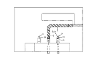
主キャビティ2内への溶融樹脂の充填後に、図5に示されるように、主キャビティ2中に充填した樹脂がキャビティ外壁面から固化を開始し、内部の樹脂が固化していない状態で開閉手段13を開放して連通路21を開く。この状態で、図6に示すように、加圧ポート6の先端ノズル18から加圧流体を圧入すると、フローティングコア12は充填樹脂内に中空部を形成しながら排出口へ向かって移動する。これと共に、フローティングコア12の移動によって押し出された余剰樹脂は副キャビティ4内へ排出される。
After the molten resin is filled into the main cavity 2, as shown in FIG. 5, the resin filled in the main cavity 2 starts to solidify from the outer wall surface of the cavity, and the opening / closing means is in a state where the resin inside is not solidified. 13 is opened and the
加圧流体としては、射出成形の温度及び圧力下で使用樹脂と反応又は相溶しない気体又は液体が使用される。具体的には、例えば窒素ガス、炭酸ガス、空気、水、グリセリン、流動パラフィン等が使用できるが、窒素ガスをはじめとする不活性ガスが好ましい。この加圧流体の圧入は、例えば窒素ガス等の気体を用いる場合、予め圧縮機で畜圧タンク(図示されていない)内に昇圧して蓄えた加圧ガスを配管を通じて加圧ポート5,6に導くことや、圧縮機で直接加圧ポート5,6に加圧ガスを送り込んで昇圧させることでおこなう事ができる。加圧ポート5,6に供給する加圧ガスの圧力は、使用する樹脂の種類やフローティングコア12の大きさなどによっても相違するが、通常4.90〜29.42MPa(50〜300kg/cm2G)程度である。
As the pressurized fluid, a gas or liquid that does not react with or compatible with the resin used under the temperature and pressure of injection molding is used. Specifically, for example, nitrogen gas, carbon dioxide gas, air, water, glycerin, liquid paraffin and the like can be used, but inert gas including nitrogen gas is preferable. For example, when a gas such as nitrogen gas is used, the pressurization of the pressurized fluid is performed by pressurizing ports 5 and 6 through the pipes of the pressurized gas that has been previously pressurized and stored in the animal pressure tank (not shown) by a compressor. Or by increasing the pressure by sending the pressurized gas directly into the pressure ports 5 and 6 with a compressor. The pressure of the pressurized gas supplied to the pressure ports 5 and 6 varies depending on the type of resin used and the size of the floating
フローティングコア12の移動により、図6に示されるように中空成形体15が得られる。これと同時に、フローティングコアキャビティ8に充填された樹脂が冷却固化し、同一の金型1内でフローティングコア12aが成形される。ここで、加圧ポート5の先端ノズル17がフローティングコア12aに凹部を形成するコアとして機能するため、フローティングコア12aには凹部が形成される。従って、加圧ポート5の先端ノズル17がフローティングコア12aの凹部に嵌挿された状態、即ちフローティングコア12aが加圧ポート5に装着された状態でフローティングコア12aが成形される。
By moving the floating
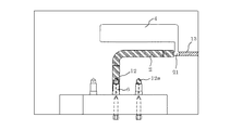
中空成形体15、副キャビティ4に収容された成形体16及びフローティングコア12aが固化した後、図7に示されるように、加圧ポート台座7が下降すると共に、不図示の可動型が移動して型開きされる。そして、金型1内から成形された中空成形体15及び副キャビティ4に収容された成形体16が取り出され、切断部19,20にて切断される。しかし、図8に示されるように、フローティングコアキャビティ8で成形されたフローティングコア12aは、加圧ポート5の先端ノズル17に装着されたままの状態で残留される。
After the hollow molded
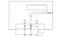
次にこの型開き状態で、図9に示されるように、加圧ポート台座7を図中左方向へスライド移動させる。そして図10に示されるように、固定型と可動型とを型組みし、加圧ポート台座7を上昇させて、主キャビティ2の一端側(基端側)の内部に加圧ポート5上に装着されたフローティングコア12aを侵入させる。
Next, in this mold open state, as shown in FIG. 9, the
次いで図11に示されるように、主キャビティ2内へ射出ゲート3から溶融樹脂を充填すると共に、フローティングコアキャビティ9内へ射出ゲート11から溶融樹脂を充填する。フローティングコアキャビティ9内には、溶融樹脂の充填に際して、待機中の加圧ポート6が配置されている。この間、フローティングコアキャビティ8の射出ゲート10及び開閉手段13は閉じた状態となっている。
Next, as shown in FIG. 11, the molten resin is filled into the main cavity 2 from the injection gate 3, and the molten resin is filled into the floating core cavity 9 from the
次に図12に示されるように、主キャビティ2中に充填した樹脂がキャビティ外壁面から固化を開始し、内部の樹脂が固化していない状態で開閉手段13を開放して連通路21を開く。この状態で、図13に示すように、加圧ポート5の先端ノズル17から加圧流体を圧入すると、フローティングコア12aは充填樹脂内に中空部を形成しながら排出口へ向かって移動する。これと共に、フローティングコア12aの移動によって押し出された余剰樹脂は副キャビティ4内へ排出される。そして、フローティングコア12aの移動により、中空成形体15が得られ、その成形と同時にフローティングコアキャビティ9に充填された樹脂が冷却固化し、同一の金型1内でフローティングコア12bが成形される。ここで、加圧ポート6の先端ノズル18がフローティングコア12bに凹部を形成するコアとして機能するため、フローティングコア12bには凹部が形成される。従って、加圧ポート6の先端ノズル18がフローティングコア12bの凹部に嵌挿された状態、即ちフローティングコア12bが加圧ポート6に装着された状態でフローティングコア12bが成形される。
Next, as shown in FIG. 12, the resin filled in the main cavity 2 starts to solidify from the outer wall surface of the cavity, and the opening / closing means 13 is opened to open the
中空成形体15、副キャビティ4に収容された成形体16及びフローティングコア12bが固化した後、図14に示されるように、加圧ポート台座7が下降すると共に、不図示の可動型が移動して型開きされる。そして、金型1内から成形された中空成形体15及び副キャビティ4に収容された成形体16が取り出され、切断部19,20にて切断される。しかし、図15に示されるように、フローティングコアキャビティ9で成形されたフローティングコア12bは、加圧ポート6の先端ノズル18に装着されたままの状態で残留される。
After the hollow molded
次にこの型開き状態で、図16に示されるように、加圧ポート台座7を図中右方向へスライド移動させる。そして、加圧ポート台座7を上昇させて、主キャビティ2の一端側(基端側)の内部に加圧ポート6上に装着されたフローティングコア12bを臨ませる。この状態は、図3と同じ状態に戻ることとなる。このような一連の操作を繰り返すことによって、フローティングコア12a,12bを、次のショットの加圧ポート上に装着された状態で成形することができ、中空成形体15を効率よく連続的に成形することができる。
Next, in this mold open state, as shown in FIG. 16, the
本発明により得られる中空成形体(屈曲パイプ)15の概要図を図17に示す。本実施形態の中空体成形装置で作製される屈曲部を有する中空成形体15は、自動車の冷却系パイプや各種熱交換器用パイプとしての利用に好適である。
A schematic view of a hollow molded body (bent pipe) 15 obtained by the present invention is shown in FIG. The hollow molded
以上説明したように、本実施形態の中空体成形装置によれば、同一金型1内で、屈曲パイプ15の成形と共にフローティングコア12a,12bを同時に成形し、かつフローティングコア12a,12bは、金型1内で次のショットの加圧ポート5,6上に装着された状態で成形されるため、そのまま次のショットに使用できる。したがって、人手やハンドリングロボット等を用いず、成形サイクルの効率化及び短縮化を図ることができる。
As described above, according to the hollow body forming apparatus of the present embodiment, the floating
以上、本発明の好適な実施形態を説明したが、これは本発明の説明のための例示であり、本発明の要旨を逸脱しない範囲で、上記実施形態とは異なる種々の態様で実施することができる。 The preferred embodiment of the present invention has been described above. However, this is merely an example for explaining the present invention, and various embodiments different from the above-described embodiment may be implemented without departing from the gist of the present invention. Can do.
図1から図16の加圧ポート台座7は、平行移動可能に、具体的には昇降移動可能であると共に、左右にスライド移動可能に形成している。加圧ポート台座7は、これに限定されず、例えば、垂直方向または斜め方向にスライド移動可能に形成してもよい。また、図18に示されるように、例えば、シリンダ装置等によって昇降可能であると共に、回転駆動手段を備えて回転可能な構造を採用してもよい。図18(a)は加圧ポート台座7の上面図であり、図18(b)は、図18(a)の加圧ポート台座7を用いた中空体成形装置を示す概略図である。加圧ポート台座7を移動させる構造は、製品形状、金型構造により任意に変更可能である。
The
また、フローティングコアキャビティ及びこれらに対応する加圧ポートの数は成形サイクルをさらに短縮化するために、それぞれ2基以上とすることも可能である。 Further, the number of floating core cavities and the corresponding pressure ports can be two or more in order to further shorten the molding cycle.
本発明に係る中空体成形装置は、自動車の冷却系パイプや各種熱交換器用パイプ等の屈曲部を有する中空成形体(屈曲パイプ)の製造に適用可能である。 The hollow body forming apparatus according to the present invention can be applied to the manufacture of a hollow molded body (bent pipe) having a bent portion such as a cooling system pipe of an automobile and various heat exchanger pipes.
1 金型
2 主キャビティ
3、10、11 射出ゲート
4 副キャビティ
5、6 加圧ポート
7 加圧ポート台座
8、9 フローティングコアキャビティ
12(12a、12b) フローティングコア
13 開閉手段
15 中空成形体
16 副キャビティの成形体
17、18 先端ノズル
19、20 切断部
21 連通路
1 Mold 2
Claims (5)
前記金型は、前記主キャビティの加圧ポート側の周囲に前記フローティングコアを成形する複数のフローティングコアキャビティを有し、
前記金型に対して移動可能に加圧ポート台座が配設されると共に、該加圧ポート台座に複数の加圧ポートが配設され、
前記主キャビティ内で中空成形体を成形すると共に、前記フローティングコアキャビティのうち少なくとも一つに、待機中の加圧ポートを臨ませて該加圧ポート上にフローティングコアを成形し、
該成形されたフローティングコアが前記加圧ポート上に装着されたままの状態で、次のショットに際して前記主キャビティに臨むように、前記加圧ポート台座を移動させることを特徴とする中空体成形装置。 A pressurized port having a floating core at one end is arranged, and after the molten resin is injected into the main cavity of a mold having a main cavity having a discharge port at the other end, a pressurized fluid is supplied from the pressurized port. In the hollow body forming apparatus that press-fits and moves the floating core to the discharge port side and extrudes the molten resin from the discharge port to form a hollow molded body,
The mold has a plurality of floating core cavities for molding the floating core around the pressure port side of the main cavity,
A pressure port pedestal is disposed so as to be movable with respect to the mold, and a plurality of pressure ports are disposed on the pressure port pedestal,
A hollow molded body is molded in the main cavity, and at least one of the floating core cavities faces a standby pressure port to mold a floating core on the pressure port,
A hollow body forming apparatus, wherein the pressurization port base is moved so as to face the main cavity at the time of the next shot in a state in which the molded floating core is mounted on the pressurization port. .
Priority Applications (1)
| Application Number | Priority Date | Filing Date | Title |
|---|---|---|---|
| JP2011016091A JP5658577B2 (en) | 2011-01-28 | 2011-01-28 | Hollow body forming equipment |
Applications Claiming Priority (1)
| Application Number | Priority Date | Filing Date | Title |
|---|---|---|---|
| JP2011016091A JP5658577B2 (en) | 2011-01-28 | 2011-01-28 | Hollow body forming equipment |
Publications (2)
| Publication Number | Publication Date |
|---|---|
| JP2012153086A JP2012153086A (en) | 2012-08-16 |
| JP5658577B2 true JP5658577B2 (en) | 2015-01-28 |
Family
ID=46835324
Family Applications (1)
| Application Number | Title | Priority Date | Filing Date |
|---|---|---|---|
| JP2011016091A Active JP5658577B2 (en) | 2011-01-28 | 2011-01-28 | Hollow body forming equipment |
Country Status (1)
| Country | Link |
|---|---|
| JP (1) | JP5658577B2 (en) |
Families Citing this family (4)
| Publication number | Priority date | Publication date | Assignee | Title |
|---|---|---|---|---|
| JP6310385B2 (en) * | 2014-12-24 | 2018-04-11 | 豊田鉄工株式会社 | Hollow body forming equipment |
| JP6295216B2 (en) * | 2015-02-27 | 2018-03-14 | 豊田鉄工株式会社 | Injection molding device and connected molded product |
| DE102017204797A1 (en) * | 2017-03-22 | 2018-09-27 | Kautex Textron Gmbh & Co. Kg | Method and device for producing a component made of thermoplastic material and component produced by the method |
| JP7147514B2 (en) * | 2018-11-30 | 2022-10-05 | 横浜ゴム株式会社 | Method for manufacturing resin pipe |
Family Cites Families (4)
| Publication number | Priority date | Publication date | Assignee | Title |
|---|---|---|---|---|
| JPH06320565A (en) * | 1993-05-13 | 1994-11-22 | Kyoraku Co Ltd | Production of resin tubular member |
| JP3411710B2 (en) * | 1995-02-23 | 2003-06-03 | アァルピィ東プラ株式会社 | Hollow molding method |
| JPH10180812A (en) * | 1996-12-26 | 1998-07-07 | Asahi Chem Ind Co Ltd | Method for molding hollow body with floating core |
| JPH11114997A (en) * | 1997-10-21 | 1999-04-27 | Nippon Plast Co Ltd | Manufacture of branch hollow unit |
-
2011
- 2011-01-28 JP JP2011016091A patent/JP5658577B2/en active Active
Also Published As
| Publication number | Publication date |
|---|---|
| JP2012153086A (en) | 2012-08-16 |
Similar Documents
| Publication | Publication Date | Title |
|---|---|---|
| JP5416080B2 (en) | Hollow body forming equipment | |
| EP2384877B1 (en) | Method of manufacturing pipe with branch | |
| JP5658577B2 (en) | Hollow body forming equipment | |
| CN105228804A (en) | There is the low constant voltage adapted to injection system of the mold cavity of position changeable | |
| US7993127B2 (en) | Blow molding device | |
| CN108698281B (en) | Injection molding device for producing multicomponent molded parts and method for producing multicomponent molded parts | |
| CN102712122B (en) | Injection moulding method | |
| JP6126237B2 (en) | Apparatus and method for manufacturing and filling containers | |
| KR101473946B1 (en) | Die casting die having slide unit | |
| CN108698280B (en) | Method for manufacturing the injection moulding apparatus of pipe and for manufacturing pipe | |
| KR100966877B1 (en) | Hot Runner System and Injection Molding Method using the same | |
| KR20060063956A (en) | Molding method, molding die, molded product, and molding machine | |
| JP2009148970A (en) | Molding process of two-layer hollow molded article | |
| JP4028683B2 (en) | Injection molding method and injection molding machine | |
| JP5038118B2 (en) | Molding method of two-layer hollow molded product | |
| CN110709224A (en) | Method and device for producing a component from thermoplastic and component produced by said method | |
| CN109070417B (en) | Method and device for producing a pipe from thermoplastic plastic by injection molding | |
| JP6607306B1 (en) | Injection molding system | |
| JP7363329B2 (en) | injection molding system | |
| CN105398006A (en) | Injection molding mold | |
| CN113276342A (en) | Rotary injection molding equipment and injection molding method of double-layer plastic part | |
| JP4996365B2 (en) | Pre-plastic injection molding equipment | |
| JP2002001782A (en) | In-line screw type injection molding apparatus and injection molding method | |
| TW201332739A (en) | Moulding methods and apparatus | |
| JP2006007421A (en) | Mold for molding hollow molded product and molding method |
Legal Events
| Date | Code | Title | Description |
|---|---|---|---|
| A621 | Written request for application examination |
Free format text: JAPANESE INTERMEDIATE CODE: A621 Effective date: 20131121 |
|
| A977 | Report on retrieval |
Free format text: JAPANESE INTERMEDIATE CODE: A971007 Effective date: 20141016 |
|
| A131 | Notification of reasons for refusal |
Free format text: JAPANESE INTERMEDIATE CODE: A131 Effective date: 20141021 |
|
| A521 | Request for written amendment filed |
Free format text: JAPANESE INTERMEDIATE CODE: A523 Effective date: 20141107 |
|
| TRDD | Decision of grant or rejection written | ||
| A01 | Written decision to grant a patent or to grant a registration (utility model) |
Free format text: JAPANESE INTERMEDIATE CODE: A01 Effective date: 20141125 |
|
| A61 | First payment of annual fees (during grant procedure) |
Free format text: JAPANESE INTERMEDIATE CODE: A61 Effective date: 20141128 |
|
| R150 | Certificate of patent or registration of utility model |
Ref document number: 5658577 Country of ref document: JP Free format text: JAPANESE INTERMEDIATE CODE: R150 |
|
| R250 | Receipt of annual fees |
Free format text: JAPANESE INTERMEDIATE CODE: R250 |
|
| R250 | Receipt of annual fees |
Free format text: JAPANESE INTERMEDIATE CODE: R250 |
|
| R250 | Receipt of annual fees |
Free format text: JAPANESE INTERMEDIATE CODE: R250 |
|
| R250 | Receipt of annual fees |
Free format text: JAPANESE INTERMEDIATE CODE: R250 |
|
| R250 | Receipt of annual fees |
Free format text: JAPANESE INTERMEDIATE CODE: R250 |
|
| R250 | Receipt of annual fees |
Free format text: JAPANESE INTERMEDIATE CODE: R250 |
|
| R250 | Receipt of annual fees |
Free format text: JAPANESE INTERMEDIATE CODE: R250 |