JP5658561B2 - Nano surface - Google Patents
Nano surface Download PDFInfo
- Publication number
- JP5658561B2 JP5658561B2 JP2010515496A JP2010515496A JP5658561B2 JP 5658561 B2 JP5658561 B2 JP 5658561B2 JP 2010515496 A JP2010515496 A JP 2010515496A JP 2010515496 A JP2010515496 A JP 2010515496A JP 5658561 B2 JP5658561 B2 JP 5658561B2
- Authority
- JP
- Japan
- Prior art keywords
- implant
- range
- titanium
- biocompatible
- nanostructure
- Prior art date
- Legal status (The legal status is an assumption and is not a legal conclusion. Google has not performed a legal analysis and makes no representation as to the accuracy of the status listed.)
- Active
Links
- 239000007943 implant Substances 0.000 claims abstract description 183
- 239000002086 nanomaterial Substances 0.000 claims abstract description 110
- 210000000988 bone and bone Anatomy 0.000 claims abstract description 68
- 239000000758 substrate Substances 0.000 claims abstract description 13
- 238000000034 method Methods 0.000 claims description 87
- 239000010936 titanium Substances 0.000 claims description 82
- 229910052719 titanium Inorganic materials 0.000 claims description 79
- MUBZPKHOEPUJKR-UHFFFAOYSA-N Oxalic acid Chemical compound OC(=O)C(O)=O MUBZPKHOEPUJKR-UHFFFAOYSA-N 0.000 claims description 78
- RTAQQCXQSZGOHL-UHFFFAOYSA-N Titanium Chemical compound [Ti] RTAQQCXQSZGOHL-UHFFFAOYSA-N 0.000 claims description 74
- 239000000203 mixture Substances 0.000 claims description 51
- 229910044991 metal oxide Inorganic materials 0.000 claims description 34
- 150000004706 metal oxides Chemical class 0.000 claims description 34
- 239000000126 substance Substances 0.000 claims description 33
- KRHYYFGTRYWZRS-UHFFFAOYSA-N Fluorane Chemical compound F KRHYYFGTRYWZRS-UHFFFAOYSA-N 0.000 claims description 29
- 235000006408 oxalic acid Nutrition 0.000 claims description 26
- 238000011282 treatment Methods 0.000 claims description 26
- 239000000463 material Substances 0.000 claims description 18
- OGIDPMRJRNCKJF-UHFFFAOYSA-N titanium oxide Inorganic materials [Ti]=O OGIDPMRJRNCKJF-UHFFFAOYSA-N 0.000 claims description 17
- 230000008468 bone growth Effects 0.000 claims description 15
- 230000008569 process Effects 0.000 claims description 15
- GWEVSGVZZGPLCZ-UHFFFAOYSA-N Titan oxide Chemical compound O=[Ti]=O GWEVSGVZZGPLCZ-UHFFFAOYSA-N 0.000 claims description 14
- 229910021645 metal ion Inorganic materials 0.000 claims description 14
- 238000005422 blasting Methods 0.000 claims description 13
- 230000002708 enhancing effect Effects 0.000 claims description 13
- 239000012298 atmosphere Substances 0.000 claims description 11
- QVGXLLKOCUKJST-UHFFFAOYSA-N atomic oxygen Chemical compound [O] QVGXLLKOCUKJST-UHFFFAOYSA-N 0.000 claims description 11
- 239000001301 oxygen Substances 0.000 claims description 11
- 229910052760 oxygen Inorganic materials 0.000 claims description 11
- 229910001416 lithium ion Inorganic materials 0.000 claims description 10
- 238000012545 processing Methods 0.000 claims description 10
- 229910001427 strontium ion Inorganic materials 0.000 claims description 10
- HBBGRARXTFLTSG-UHFFFAOYSA-N Lithium ion Chemical compound [Li+] HBBGRARXTFLTSG-UHFFFAOYSA-N 0.000 claims description 9
- ZAMOUSCENKQFHK-UHFFFAOYSA-N Chlorine atom Chemical compound [Cl] ZAMOUSCENKQFHK-UHFFFAOYSA-N 0.000 claims description 8
- PXGOKWXKJXAPGV-UHFFFAOYSA-N Fluorine Chemical compound FF PXGOKWXKJXAPGV-UHFFFAOYSA-N 0.000 claims description 8
- 239000002253 acid Substances 0.000 claims description 8
- 239000000460 chlorine Substances 0.000 claims description 8
- 229910052801 chlorine Inorganic materials 0.000 claims description 8
- 229910052731 fluorine Inorganic materials 0.000 claims description 8
- 239000011737 fluorine Substances 0.000 claims description 8
- 238000004381 surface treatment Methods 0.000 claims description 8
- 150000003839 salts Chemical class 0.000 claims description 7
- 230000000399 orthopedic effect Effects 0.000 claims description 6
- BHPQYMZQTOCNFJ-UHFFFAOYSA-N Calcium cation Chemical compound [Ca+2] BHPQYMZQTOCNFJ-UHFFFAOYSA-N 0.000 claims description 5
- JLVVSXFLKOJNIY-UHFFFAOYSA-N Magnesium ion Chemical compound [Mg+2] JLVVSXFLKOJNIY-UHFFFAOYSA-N 0.000 claims description 5
- 229910001069 Ti alloy Inorganic materials 0.000 claims description 5
- 229910001424 calcium ion Inorganic materials 0.000 claims description 5
- 238000004140 cleaning Methods 0.000 claims description 5
- 229910001425 magnesium ion Inorganic materials 0.000 claims description 5
- SOQBVABWOPYFQZ-UHFFFAOYSA-N oxygen(2-);titanium(4+) Chemical class [O-2].[O-2].[Ti+4] SOQBVABWOPYFQZ-UHFFFAOYSA-N 0.000 claims description 4
- -1 titanium ions Chemical class 0.000 claims description 4
- 230000004913 activation Effects 0.000 claims description 3
- 150000002500 ions Chemical class 0.000 claims description 3
- LCKIEQZJEYYRIY-UHFFFAOYSA-N Titanium ion Chemical compound [Ti+4] LCKIEQZJEYYRIY-UHFFFAOYSA-N 0.000 claims description 2
- 238000005238 degreasing Methods 0.000 claims description 2
- PWYYWQHXAPXYMF-UHFFFAOYSA-N strontium(2+) Chemical compound [Sr+2] PWYYWQHXAPXYMF-UHFFFAOYSA-N 0.000 claims 2
- 230000001568 sexual effect Effects 0.000 claims 1
- 238000010883 osseointegration Methods 0.000 abstract description 15
- 230000003993 interaction Effects 0.000 abstract description 5
- 239000000523 sample Substances 0.000 description 63
- 210000004027 cell Anatomy 0.000 description 35
- 238000012360 testing method Methods 0.000 description 28
- 229910052751 metal Inorganic materials 0.000 description 20
- 239000002184 metal Substances 0.000 description 20
- 239000012890 simulated body fluid Substances 0.000 description 20
- 238000009826 distribution Methods 0.000 description 18
- 230000015572 biosynthetic process Effects 0.000 description 15
- 238000002513 implantation Methods 0.000 description 15
- 238000001000 micrograph Methods 0.000 description 15
- 239000000243 solution Substances 0.000 description 15
- 241000283973 Oryctolagus cuniculus Species 0.000 description 14
- 230000000694 effects Effects 0.000 description 13
- 210000000963 osteoblast Anatomy 0.000 description 13
- XLYOFNOQVPJJNP-UHFFFAOYSA-N water Substances O XLYOFNOQVPJJNP-UHFFFAOYSA-N 0.000 description 13
- 229910052586 apatite Inorganic materials 0.000 description 12
- 238000004519 manufacturing process Methods 0.000 description 12
- VSIIXMUUUJUKCM-UHFFFAOYSA-D pentacalcium;fluoride;triphosphate Chemical compound [F-].[Ca+2].[Ca+2].[Ca+2].[Ca+2].[Ca+2].[O-]P([O-])([O-])=O.[O-]P([O-])([O-])=O.[O-]P([O-])([O-])=O VSIIXMUUUJUKCM-UHFFFAOYSA-D 0.000 description 12
- 230000003746 surface roughness Effects 0.000 description 11
- 210000001519 tissue Anatomy 0.000 description 11
- 102000002260 Alkaline Phosphatase Human genes 0.000 description 10
- 108020004774 Alkaline Phosphatase Proteins 0.000 description 10
- 238000007654 immersion Methods 0.000 description 10
- 239000010410 layer Substances 0.000 description 10
- 229910045601 alloy Inorganic materials 0.000 description 9
- 239000000956 alloy Substances 0.000 description 9
- 239000011575 calcium Substances 0.000 description 9
- XEYBRNLFEZDVAW-ARSRFYASSA-N dinoprostone Chemical compound CCCCC[C@H](O)\C=C\[C@H]1[C@H](O)CC(=O)[C@@H]1C\C=C/CCCC(O)=O XEYBRNLFEZDVAW-ARSRFYASSA-N 0.000 description 9
- 230000001965 increasing effect Effects 0.000 description 9
- 230000011164 ossification Effects 0.000 description 9
- 238000001878 scanning electron micrograph Methods 0.000 description 9
- WHXSMMKQMYFTQS-UHFFFAOYSA-N Lithium Chemical compound [Li] WHXSMMKQMYFTQS-UHFFFAOYSA-N 0.000 description 8
- 241001465754 Metazoa Species 0.000 description 8
- 238000000576 coating method Methods 0.000 description 8
- 229960002986 dinoprostone Drugs 0.000 description 8
- 229910052588 hydroxylapatite Inorganic materials 0.000 description 8
- XYJRXVWERLGGKC-UHFFFAOYSA-D pentacalcium;hydroxide;triphosphate Chemical compound [OH-].[Ca+2].[Ca+2].[Ca+2].[Ca+2].[Ca+2].[O-]P([O-])([O-])=O.[O-]P([O-])([O-])=O.[O-]P([O-])([O-])=O XYJRXVWERLGGKC-UHFFFAOYSA-D 0.000 description 8
- XEYBRNLFEZDVAW-UHFFFAOYSA-N prostaglandin E2 Natural products CCCCCC(O)C=CC1C(O)CC(=O)C1CC=CCCCC(O)=O XEYBRNLFEZDVAW-UHFFFAOYSA-N 0.000 description 8
- 239000007864 aqueous solution Substances 0.000 description 7
- 239000012620 biological material Substances 0.000 description 7
- 230000035876 healing Effects 0.000 description 7
- 229910052744 lithium Inorganic materials 0.000 description 7
- QPJSUIGXIBEQAC-UHFFFAOYSA-N n-(2,4-dichloro-5-propan-2-yloxyphenyl)acetamide Chemical compound CC(C)OC1=CC(NC(C)=O)=C(Cl)C=C1Cl QPJSUIGXIBEQAC-UHFFFAOYSA-N 0.000 description 7
- 229910052712 strontium Inorganic materials 0.000 description 7
- CIOAGBVUUVVLOB-UHFFFAOYSA-N strontium atom Chemical compound [Sr] CIOAGBVUUVVLOB-UHFFFAOYSA-N 0.000 description 7
- 238000012876 topography Methods 0.000 description 7
- 239000001506 calcium phosphate Substances 0.000 description 6
- 238000011555 rabbit model Methods 0.000 description 6
- 239000013074 reference sample Substances 0.000 description 6
- QORWJWZARLRLPR-UHFFFAOYSA-H tricalcium bis(phosphate) Chemical compound [Ca+2].[Ca+2].[Ca+2].[O-]P([O-])([O-])=O.[O-]P([O-])([O-])=O QORWJWZARLRLPR-UHFFFAOYSA-H 0.000 description 6
- FAPWRFPIFSIZLT-UHFFFAOYSA-M Sodium chloride Chemical compound [Na+].[Cl-] FAPWRFPIFSIZLT-UHFFFAOYSA-M 0.000 description 5
- QCWXUUIWCKQGHC-UHFFFAOYSA-N Zirconium Chemical compound [Zr] QCWXUUIWCKQGHC-UHFFFAOYSA-N 0.000 description 5
- 229910000389 calcium phosphate Inorganic materials 0.000 description 5
- 235000011010 calcium phosphates Nutrition 0.000 description 5
- 230000004663 cell proliferation Effects 0.000 description 5
- 239000011248 coating agent Substances 0.000 description 5
- 238000004090 dissolution Methods 0.000 description 5
- 238000002389 environmental scanning electron microscopy Methods 0.000 description 5
- 238000011156 evaluation Methods 0.000 description 5
- 229910052758 niobium Inorganic materials 0.000 description 5
- 239000010955 niobium Substances 0.000 description 5
- GUCVJGMIXFAOAE-UHFFFAOYSA-N niobium atom Chemical compound [Nb] GUCVJGMIXFAOAE-UHFFFAOYSA-N 0.000 description 5
- 238000010915 one-step procedure Methods 0.000 description 5
- 230000002829 reductive effect Effects 0.000 description 5
- 229910052715 tantalum Inorganic materials 0.000 description 5
- GUVRBAGPIYLISA-UHFFFAOYSA-N tantalum atom Chemical compound [Ta] GUVRBAGPIYLISA-UHFFFAOYSA-N 0.000 description 5
- 229910052726 zirconium Inorganic materials 0.000 description 5
- 241001132374 Asta Species 0.000 description 4
- 238000004113 cell culture Methods 0.000 description 4
- 230000000875 corresponding effect Effects 0.000 description 4
- 239000004053 dental implant Substances 0.000 description 4
- 238000010586 diagram Methods 0.000 description 4
- 230000006870 function Effects 0.000 description 4
- 229910052735 hafnium Inorganic materials 0.000 description 4
- VBJZVLUMGGDVMO-UHFFFAOYSA-N hafnium atom Chemical compound [Hf] VBJZVLUMGGDVMO-UHFFFAOYSA-N 0.000 description 4
- 238000000338 in vitro Methods 0.000 description 4
- 238000011068 loading method Methods 0.000 description 4
- 102000004169 proteins and genes Human genes 0.000 description 4
- 108090000623 proteins and genes Proteins 0.000 description 4
- 230000004044 response Effects 0.000 description 4
- 238000001356 surgical procedure Methods 0.000 description 4
- 210000000689 upper leg Anatomy 0.000 description 4
- JKMHFZQWWAIEOD-UHFFFAOYSA-N 2-[4-(2-hydroxyethyl)piperazin-1-yl]ethanesulfonic acid Chemical compound OCC[NH+]1CCN(CCS([O-])(=O)=O)CC1 JKMHFZQWWAIEOD-UHFFFAOYSA-N 0.000 description 3
- 102000010834 Extracellular Matrix Proteins Human genes 0.000 description 3
- 108010037362 Extracellular Matrix Proteins Proteins 0.000 description 3
- UFHFLCQGNIYNRP-UHFFFAOYSA-N Hydrogen Chemical compound [H][H] UFHFLCQGNIYNRP-UHFFFAOYSA-N 0.000 description 3
- HEMHJVSKTPXQMS-UHFFFAOYSA-M Sodium hydroxide Chemical compound [OH-].[Na+] HEMHJVSKTPXQMS-UHFFFAOYSA-M 0.000 description 3
- 241000607479 Yersinia pestis Species 0.000 description 3
- 230000001464 adherent effect Effects 0.000 description 3
- 238000004458 analytical method Methods 0.000 description 3
- 210000001185 bone marrow Anatomy 0.000 description 3
- 210000002805 bone matrix Anatomy 0.000 description 3
- 230000002308 calcification Effects 0.000 description 3
- 238000006243 chemical reaction Methods 0.000 description 3
- 239000003153 chemical reaction reagent Substances 0.000 description 3
- 239000008367 deionised water Substances 0.000 description 3
- 229910021641 deionized water Inorganic materials 0.000 description 3
- 238000000151 deposition Methods 0.000 description 3
- 238000013461 design Methods 0.000 description 3
- 238000002845 discoloration Methods 0.000 description 3
- 230000004821 effect on bone Effects 0.000 description 3
- 238000002149 energy-dispersive X-ray emission spectroscopy Methods 0.000 description 3
- 238000005530 etching Methods 0.000 description 3
- 210000002744 extracellular matrix Anatomy 0.000 description 3
- 239000007769 metal material Substances 0.000 description 3
- 150000002739 metals Chemical class 0.000 description 3
- 230000004048 modification Effects 0.000 description 3
- 238000012986 modification Methods 0.000 description 3
- 238000013425 morphometry Methods 0.000 description 3
- 239000002159 nanocrystal Substances 0.000 description 3
- 210000002997 osteoclast Anatomy 0.000 description 3
- 230000003239 periodontal effect Effects 0.000 description 3
- 238000002360 preparation method Methods 0.000 description 3
- 230000035755 proliferation Effects 0.000 description 3
- 239000011780 sodium chloride Substances 0.000 description 3
- 210000004872 soft tissue Anatomy 0.000 description 3
- 230000001954 sterilising effect Effects 0.000 description 3
- 238000004659 sterilization and disinfection Methods 0.000 description 3
- 238000003756 stirring Methods 0.000 description 3
- XKRFYHLGVUSROY-UHFFFAOYSA-N Argon Chemical compound [Ar] XKRFYHLGVUSROY-UHFFFAOYSA-N 0.000 description 2
- IJGRMHOSHXDMSA-UHFFFAOYSA-N Atomic nitrogen Chemical compound N#N IJGRMHOSHXDMSA-UHFFFAOYSA-N 0.000 description 2
- OYPRJOBELJOOCE-UHFFFAOYSA-N Calcium Chemical compound [Ca] OYPRJOBELJOOCE-UHFFFAOYSA-N 0.000 description 2
- 239000007995 HEPES buffer Substances 0.000 description 2
- FYYHWMGAXLPEAU-UHFFFAOYSA-N Magnesium Chemical compound [Mg] FYYHWMGAXLPEAU-UHFFFAOYSA-N 0.000 description 2
- 230000002411 adverse Effects 0.000 description 2
- 230000004071 biological effect Effects 0.000 description 2
- 229910052791 calcium Inorganic materials 0.000 description 2
- 229910002091 carbon monoxide Inorganic materials 0.000 description 2
- 230000024245 cell differentiation Effects 0.000 description 2
- 230000003915 cell function Effects 0.000 description 2
- 239000011247 coating layer Substances 0.000 description 2
- 230000000052 comparative effect Effects 0.000 description 2
- 230000008021 deposition Effects 0.000 description 2
- 238000005553 drilling Methods 0.000 description 2
- 229940079593 drug Drugs 0.000 description 2
- 239000003814 drug Substances 0.000 description 2
- PCHJSUWPFVWCPO-UHFFFAOYSA-N gold Chemical compound [Au] PCHJSUWPFVWCPO-UHFFFAOYSA-N 0.000 description 2
- 239000010931 gold Substances 0.000 description 2
- 229910052737 gold Inorganic materials 0.000 description 2
- 230000012010 growth Effects 0.000 description 2
- 230000006872 improvement Effects 0.000 description 2
- 238000010874 in vitro model Methods 0.000 description 2
- 238000001727 in vivo Methods 0.000 description 2
- 239000011261 inert gas Substances 0.000 description 2
- 229910052500 inorganic mineral Inorganic materials 0.000 description 2
- 238000003780 insertion Methods 0.000 description 2
- 230000037431 insertion Effects 0.000 description 2
- 230000001788 irregular Effects 0.000 description 2
- 229910052749 magnesium Inorganic materials 0.000 description 2
- 239000011777 magnesium Substances 0.000 description 2
- 239000011159 matrix material Substances 0.000 description 2
- 239000011707 mineral Substances 0.000 description 2
- 239000003960 organic solvent Substances 0.000 description 2
- 210000005009 osteogenic cell Anatomy 0.000 description 2
- 239000002245 particle Substances 0.000 description 2
- 239000002244 precipitate Substances 0.000 description 2
- 239000002243 precursor Substances 0.000 description 2
- 230000001737 promoting effect Effects 0.000 description 2
- 238000007788 roughening Methods 0.000 description 2
- 230000028327 secretion Effects 0.000 description 2
- 238000004544 sputter deposition Methods 0.000 description 2
- 238000003860 storage Methods 0.000 description 2
- 239000006228 supernatant Substances 0.000 description 2
- AZUYLZMQTIKGSC-UHFFFAOYSA-N 1-[6-[4-(5-chloro-6-methyl-1H-indazol-4-yl)-5-methyl-3-(1-methylindazol-5-yl)pyrazol-1-yl]-2-azaspiro[3.3]heptan-2-yl]prop-2-en-1-one Chemical compound ClC=1C(=C2C=NNC2=CC=1C)C=1C(=NN(C=1C)C1CC2(CN(C2)C(C=C)=O)C1)C=1C=C2C=NN(C2=CC=1)C AZUYLZMQTIKGSC-UHFFFAOYSA-N 0.000 description 1
- XNWFRZJHXBZDAG-UHFFFAOYSA-N 2-METHOXYETHANOL Chemical compound COCCO XNWFRZJHXBZDAG-UHFFFAOYSA-N 0.000 description 1
- XZKIHKMTEMTJQX-UHFFFAOYSA-N 4-Nitrophenyl Phosphate Chemical compound OP(O)(=O)OC1=CC=C([N+]([O-])=O)C=C1 XZKIHKMTEMTJQX-UHFFFAOYSA-N 0.000 description 1
- 238000008940 Alkaline Phosphatase assay kit Methods 0.000 description 1
- 206010002091 Anaesthesia Diseases 0.000 description 1
- 102000007350 Bone Morphogenetic Proteins Human genes 0.000 description 1
- 108010007726 Bone Morphogenetic Proteins Proteins 0.000 description 1
- 208000006386 Bone Resorption Diseases 0.000 description 1
- 108091003079 Bovine Serum Albumin Proteins 0.000 description 1
- 102000008186 Collagen Human genes 0.000 description 1
- 108010035532 Collagen Proteins 0.000 description 1
- 238000008157 ELISA kit Methods 0.000 description 1
- 208000002354 Edentulous Jaw Diseases 0.000 description 1
- 229910001200 Ferrotitanium Inorganic materials 0.000 description 1
- SXRSQZLOMIGNAQ-UHFFFAOYSA-N Glutaraldehyde Chemical compound O=CCCCC=O SXRSQZLOMIGNAQ-UHFFFAOYSA-N 0.000 description 1
- 241000124008 Mammalia Species 0.000 description 1
- 239000004793 Polystyrene Substances 0.000 description 1
- 238000000692 Student's t-test Methods 0.000 description 1
- 229910010413 TiO 2 Inorganic materials 0.000 description 1
- 229910000756 V alloy Inorganic materials 0.000 description 1
- 241000251539 Vertebrata <Metazoa> Species 0.000 description 1
- 238000010306 acid treatment Methods 0.000 description 1
- 230000002378 acidificating effect Effects 0.000 description 1
- 210000001789 adipocyte Anatomy 0.000 description 1
- 230000037005 anaesthesia Effects 0.000 description 1
- 210000003484 anatomy Anatomy 0.000 description 1
- 229910052786 argon Inorganic materials 0.000 description 1
- 239000011324 bead Substances 0.000 description 1
- 230000009286 beneficial effect Effects 0.000 description 1
- 210000002798 bone marrow cell Anatomy 0.000 description 1
- 229940112869 bone morphogenetic protein Drugs 0.000 description 1
- 230000010072 bone remodeling Effects 0.000 description 1
- 230000024279 bone resorption Effects 0.000 description 1
- 210000000845 cartilage Anatomy 0.000 description 1
- 230000021164 cell adhesion Effects 0.000 description 1
- 230000006037 cell lysis Effects 0.000 description 1
- 230000003833 cell viability Effects 0.000 description 1
- 230000001413 cellular effect Effects 0.000 description 1
- 238000005119 centrifugation Methods 0.000 description 1
- 239000000919 ceramic Substances 0.000 description 1
- 238000005524 ceramic coating Methods 0.000 description 1
- 229910010293 ceramic material Inorganic materials 0.000 description 1
- 238000012512 characterization method Methods 0.000 description 1
- HBXWYZMULLEJSG-UHFFFAOYSA-N chromium vanadium Chemical compound [V][Cr][V][Cr] HBXWYZMULLEJSG-UHFFFAOYSA-N 0.000 description 1
- 229920001436 collagen Polymers 0.000 description 1
- 239000000084 colloidal system Substances 0.000 description 1
- 239000008139 complexing agent Substances 0.000 description 1
- 239000002131 composite material Substances 0.000 description 1
- 150000001875 compounds Chemical class 0.000 description 1
- 238000011109 contamination Methods 0.000 description 1
- 238000001816 cooling Methods 0.000 description 1
- 230000001054 cortical effect Effects 0.000 description 1
- 230000003247 decreasing effect Effects 0.000 description 1
- 230000007547 defect Effects 0.000 description 1
- 230000001419 dependent effect Effects 0.000 description 1
- 230000004069 differentiation Effects 0.000 description 1
- 238000001035 drying Methods 0.000 description 1
- 239000003792 electrolyte Substances 0.000 description 1
- 238000005516 engineering process Methods 0.000 description 1
- 230000007613 environmental effect Effects 0.000 description 1
- 239000012894 fetal calf serum Substances 0.000 description 1
- 239000000834 fixative Substances 0.000 description 1
- 210000001650 focal adhesion Anatomy 0.000 description 1
- 238000009472 formulation Methods 0.000 description 1
- 239000003102 growth factor Substances 0.000 description 1
- 239000001307 helium Substances 0.000 description 1
- 229910052734 helium Inorganic materials 0.000 description 1
- SWQJXJOGLNCZEY-UHFFFAOYSA-N helium atom Chemical compound [He] SWQJXJOGLNCZEY-UHFFFAOYSA-N 0.000 description 1
- 210000005260 human cell Anatomy 0.000 description 1
- 230000028993 immune response Effects 0.000 description 1
- 238000003018 immunoassay Methods 0.000 description 1
- 238000011534 incubation Methods 0.000 description 1
- 238000007373 indentation Methods 0.000 description 1
- 230000010354 integration Effects 0.000 description 1
- 102000006495 integrins Human genes 0.000 description 1
- 108010044426 integrins Proteins 0.000 description 1
- 238000004573 interface analysis Methods 0.000 description 1
- 230000003834 intracellular effect Effects 0.000 description 1
- 230000004068 intracellular signaling Effects 0.000 description 1
- 229910052743 krypton Inorganic materials 0.000 description 1
- DNNSSWSSYDEUBZ-UHFFFAOYSA-N krypton atom Chemical compound [Kr] DNNSSWSSYDEUBZ-UHFFFAOYSA-N 0.000 description 1
- 230000007774 longterm Effects 0.000 description 1
- 239000002932 luster Substances 0.000 description 1
- 230000014759 maintenance of location Effects 0.000 description 1
- 238000005259 measurement Methods 0.000 description 1
- 238000010297 mechanical methods and process Methods 0.000 description 1
- 230000005226 mechanical processes and functions Effects 0.000 description 1
- 230000007246 mechanism Effects 0.000 description 1
- 230000001404 mediated effect Effects 0.000 description 1
- 150000002736 metal compounds Chemical class 0.000 description 1
- 238000007491 morphometric analysis Methods 0.000 description 1
- 230000003562 morphometric effect Effects 0.000 description 1
- 239000002105 nanoparticle Substances 0.000 description 1
- 229910052754 neon Inorganic materials 0.000 description 1
- GKAOGPIIYCISHV-UHFFFAOYSA-N neon atom Chemical compound [Ne] GKAOGPIIYCISHV-UHFFFAOYSA-N 0.000 description 1
- 238000011587 new zealand white rabbit Methods 0.000 description 1
- 229910052757 nitrogen Inorganic materials 0.000 description 1
- 229910052755 nonmetal Inorganic materials 0.000 description 1
- 230000006911 nucleation Effects 0.000 description 1
- 238000010899 nucleation Methods 0.000 description 1
- 229910000489 osmium tetroxide Inorganic materials 0.000 description 1
- 239000012285 osmium tetroxide Substances 0.000 description 1
- 230000004072 osteoblast differentiation Effects 0.000 description 1
- 238000000059 patterning Methods 0.000 description 1
- 230000035479 physiological effects, processes and functions Effects 0.000 description 1
- 238000007750 plasma spraying Methods 0.000 description 1
- 239000004033 plastic Substances 0.000 description 1
- 229920003023 plastic Polymers 0.000 description 1
- 229920002223 polystyrene Polymers 0.000 description 1
- 238000001556 precipitation Methods 0.000 description 1
- 230000002062 proliferating effect Effects 0.000 description 1
- 229910052704 radon Inorganic materials 0.000 description 1
- SYUHGPGVQRZVTB-UHFFFAOYSA-N radon atom Chemical compound [Rn] SYUHGPGVQRZVTB-UHFFFAOYSA-N 0.000 description 1
- 230000009257 reactivity Effects 0.000 description 1
- 230000024155 regulation of cell adhesion Effects 0.000 description 1
- 230000001105 regulatory effect Effects 0.000 description 1
- 238000010405 reoxidation reaction Methods 0.000 description 1
- 230000008439 repair process Effects 0.000 description 1
- 238000011160 research Methods 0.000 description 1
- 230000000284 resting effect Effects 0.000 description 1
- 230000000717 retained effect Effects 0.000 description 1
- 230000003248 secreting effect Effects 0.000 description 1
- 239000002276 single tooth dental implant Substances 0.000 description 1
- 238000005245 sintering Methods 0.000 description 1
- 238000002791 soaking Methods 0.000 description 1
- 239000002904 solvent Substances 0.000 description 1
- 210000001082 somatic cell Anatomy 0.000 description 1
- 241000894007 species Species 0.000 description 1
- 239000010935 stainless steel Substances 0.000 description 1
- 229910001220 stainless steel Inorganic materials 0.000 description 1
- 238000012414 sterilization procedure Methods 0.000 description 1
- 230000004936 stimulating effect Effects 0.000 description 1
- 229960005322 streptomycin Drugs 0.000 description 1
- 230000001629 suppression Effects 0.000 description 1
- 239000002344 surface layer Substances 0.000 description 1
- 238000007669 thermal treatment Methods 0.000 description 1
- 230000008467 tissue growth Effects 0.000 description 1
- 229910000391 tricalcium phosphate Inorganic materials 0.000 description 1
- 235000019731 tricalcium phosphate Nutrition 0.000 description 1
- 229940078499 tricalcium phosphate Drugs 0.000 description 1
- 238000010246 ultrastructural analysis Methods 0.000 description 1
- 238000009827 uniform distribution Methods 0.000 description 1
- 238000005406 washing Methods 0.000 description 1
- 229910052724 xenon Inorganic materials 0.000 description 1
- FHNFHKCVQCLJFQ-UHFFFAOYSA-N xenon atom Chemical compound [Xe] FHNFHKCVQCLJFQ-UHFFFAOYSA-N 0.000 description 1
Images


Classifications
-
- A—HUMAN NECESSITIES
- A61—MEDICAL OR VETERINARY SCIENCE; HYGIENE
- A61F—FILTERS IMPLANTABLE INTO BLOOD VESSELS; PROSTHESES; DEVICES PROVIDING PATENCY TO, OR PREVENTING COLLAPSING OF, TUBULAR STRUCTURES OF THE BODY, e.g. STENTS; ORTHOPAEDIC, NURSING OR CONTRACEPTIVE DEVICES; FOMENTATION; TREATMENT OR PROTECTION OF EYES OR EARS; BANDAGES, DRESSINGS OR ABSORBENT PADS; FIRST-AID KITS
- A61F2/00—Filters implantable into blood vessels; Prostheses, i.e. artificial substitutes or replacements for parts of the body; Appliances for connecting them with the body; Devices providing patency to, or preventing collapsing of, tubular structures of the body, e.g. stents
- A61F2/02—Prostheses implantable into the body
- A61F2/30—Joints
- A61F2/30767—Special external or bone-contacting surface, e.g. coating for improving bone ingrowth
-
- A—HUMAN NECESSITIES
- A61—MEDICAL OR VETERINARY SCIENCE; HYGIENE
- A61C—DENTISTRY; APPARATUS OR METHODS FOR ORAL OR DENTAL HYGIENE
- A61C8/00—Means to be fixed to the jaw-bone for consolidating natural teeth or for fixing dental prostheses thereon; Dental implants; Implanting tools
- A61C8/0012—Means to be fixed to the jaw-bone for consolidating natural teeth or for fixing dental prostheses thereon; Dental implants; Implanting tools characterised by the material or composition, e.g. ceramics, surface layer, metal alloy
-
- A—HUMAN NECESSITIES
- A61—MEDICAL OR VETERINARY SCIENCE; HYGIENE
- A61L—METHODS OR APPARATUS FOR STERILISING MATERIALS OR OBJECTS IN GENERAL; DISINFECTION, STERILISATION OR DEODORISATION OF AIR; CHEMICAL ASPECTS OF BANDAGES, DRESSINGS, ABSORBENT PADS OR SURGICAL ARTICLES; MATERIALS FOR BANDAGES, DRESSINGS, ABSORBENT PADS OR SURGICAL ARTICLES
- A61L27/00—Materials for grafts or prostheses or for coating grafts or prostheses
- A61L27/28—Materials for coating prostheses
- A61L27/30—Inorganic materials
- A61L27/306—Other specific inorganic materials not covered by A61L27/303 - A61L27/32
-
- B—PERFORMING OPERATIONS; TRANSPORTING
- B82—NANOTECHNOLOGY
- B82Y—SPECIFIC USES OR APPLICATIONS OF NANOSTRUCTURES; MEASUREMENT OR ANALYSIS OF NANOSTRUCTURES; MANUFACTURE OR TREATMENT OF NANOSTRUCTURES
- B82Y30/00—Nanotechnology for materials or surface science, e.g. nanocomposites
-
- B—PERFORMING OPERATIONS; TRANSPORTING
- B82—NANOTECHNOLOGY
- B82Y—SPECIFIC USES OR APPLICATIONS OF NANOSTRUCTURES; MEASUREMENT OR ANALYSIS OF NANOSTRUCTURES; MANUFACTURE OR TREATMENT OF NANOSTRUCTURES
- B82Y5/00—Nanobiotechnology or nanomedicine, e.g. protein engineering or drug delivery
-
- C—CHEMISTRY; METALLURGY
- C23—COATING METALLIC MATERIAL; COATING MATERIAL WITH METALLIC MATERIAL; CHEMICAL SURFACE TREATMENT; DIFFUSION TREATMENT OF METALLIC MATERIAL; COATING BY VACUUM EVAPORATION, BY SPUTTERING, BY ION IMPLANTATION OR BY CHEMICAL VAPOUR DEPOSITION, IN GENERAL; INHIBITING CORROSION OF METALLIC MATERIAL OR INCRUSTATION IN GENERAL
- C23C—COATING METALLIC MATERIAL; COATING MATERIAL WITH METALLIC MATERIAL; SURFACE TREATMENT OF METALLIC MATERIAL BY DIFFUSION INTO THE SURFACE, BY CHEMICAL CONVERSION OR SUBSTITUTION; COATING BY VACUUM EVAPORATION, BY SPUTTERING, BY ION IMPLANTATION OR BY CHEMICAL VAPOUR DEPOSITION, IN GENERAL
- C23C22/00—Chemical surface treatment of metallic material by reaction of the surface with a reactive liquid, leaving reaction products of surface material in the coating, e.g. conversion coatings, passivation of metals
- C23C22/05—Chemical surface treatment of metallic material by reaction of the surface with a reactive liquid, leaving reaction products of surface material in the coating, e.g. conversion coatings, passivation of metals using aqueous solutions
- C23C22/06—Chemical surface treatment of metallic material by reaction of the surface with a reactive liquid, leaving reaction products of surface material in the coating, e.g. conversion coatings, passivation of metals using aqueous solutions using aqueous acidic solutions with pH less than 6
- C23C22/46—Chemical surface treatment of metallic material by reaction of the surface with a reactive liquid, leaving reaction products of surface material in the coating, e.g. conversion coatings, passivation of metals using aqueous solutions using aqueous acidic solutions with pH less than 6 containing oxalates
-
- C—CHEMISTRY; METALLURGY
- C23—COATING METALLIC MATERIAL; COATING MATERIAL WITH METALLIC MATERIAL; CHEMICAL SURFACE TREATMENT; DIFFUSION TREATMENT OF METALLIC MATERIAL; COATING BY VACUUM EVAPORATION, BY SPUTTERING, BY ION IMPLANTATION OR BY CHEMICAL VAPOUR DEPOSITION, IN GENERAL; INHIBITING CORROSION OF METALLIC MATERIAL OR INCRUSTATION IN GENERAL
- C23C—COATING METALLIC MATERIAL; COATING MATERIAL WITH METALLIC MATERIAL; SURFACE TREATMENT OF METALLIC MATERIAL BY DIFFUSION INTO THE SURFACE, BY CHEMICAL CONVERSION OR SUBSTITUTION; COATING BY VACUUM EVAPORATION, BY SPUTTERING, BY ION IMPLANTATION OR BY CHEMICAL VAPOUR DEPOSITION, IN GENERAL
- C23C26/00—Coating not provided for in groups C23C2/00 - C23C24/00
-
- C—CHEMISTRY; METALLURGY
- C23—COATING METALLIC MATERIAL; COATING MATERIAL WITH METALLIC MATERIAL; CHEMICAL SURFACE TREATMENT; DIFFUSION TREATMENT OF METALLIC MATERIAL; COATING BY VACUUM EVAPORATION, BY SPUTTERING, BY ION IMPLANTATION OR BY CHEMICAL VAPOUR DEPOSITION, IN GENERAL; INHIBITING CORROSION OF METALLIC MATERIAL OR INCRUSTATION IN GENERAL
- C23C—COATING METALLIC MATERIAL; COATING MATERIAL WITH METALLIC MATERIAL; SURFACE TREATMENT OF METALLIC MATERIAL BY DIFFUSION INTO THE SURFACE, BY CHEMICAL CONVERSION OR SUBSTITUTION; COATING BY VACUUM EVAPORATION, BY SPUTTERING, BY ION IMPLANTATION OR BY CHEMICAL VAPOUR DEPOSITION, IN GENERAL
- C23C8/00—Solid state diffusion of only non-metal elements into metallic material surfaces; Chemical surface treatment of metallic material by reaction of the surface with a reactive gas, leaving reaction products of surface material in the coating, e.g. conversion coatings, passivation of metals
- C23C8/06—Solid state diffusion of only non-metal elements into metallic material surfaces; Chemical surface treatment of metallic material by reaction of the surface with a reactive gas, leaving reaction products of surface material in the coating, e.g. conversion coatings, passivation of metals using gases
- C23C8/08—Solid state diffusion of only non-metal elements into metallic material surfaces; Chemical surface treatment of metallic material by reaction of the surface with a reactive gas, leaving reaction products of surface material in the coating, e.g. conversion coatings, passivation of metals using gases only one element being applied
- C23C8/10—Oxidising
-
- C—CHEMISTRY; METALLURGY
- C23—COATING METALLIC MATERIAL; COATING MATERIAL WITH METALLIC MATERIAL; CHEMICAL SURFACE TREATMENT; DIFFUSION TREATMENT OF METALLIC MATERIAL; COATING BY VACUUM EVAPORATION, BY SPUTTERING, BY ION IMPLANTATION OR BY CHEMICAL VAPOUR DEPOSITION, IN GENERAL; INHIBITING CORROSION OF METALLIC MATERIAL OR INCRUSTATION IN GENERAL
- C23G—CLEANING OR DE-GREASING OF METALLIC MATERIAL BY CHEMICAL METHODS OTHER THAN ELECTROLYSIS
- C23G1/00—Cleaning or pickling metallic material with solutions or molten salts
- C23G1/02—Cleaning or pickling metallic material with solutions or molten salts with acid solutions
- C23G1/10—Other heavy metals
- C23G1/106—Other heavy metals refractory metals
-
- A—HUMAN NECESSITIES
- A61—MEDICAL OR VETERINARY SCIENCE; HYGIENE
- A61C—DENTISTRY; APPARATUS OR METHODS FOR ORAL OR DENTAL HYGIENE
- A61C8/00—Means to be fixed to the jaw-bone for consolidating natural teeth or for fixing dental prostheses thereon; Dental implants; Implanting tools
- A61C8/0018—Means to be fixed to the jaw-bone for consolidating natural teeth or for fixing dental prostheses thereon; Dental implants; Implanting tools characterised by the shape
- A61C8/0037—Details of the shape
- A61C2008/0046—Textured surface, e.g. roughness, microstructure
-
- A—HUMAN NECESSITIES
- A61—MEDICAL OR VETERINARY SCIENCE; HYGIENE
- A61F—FILTERS IMPLANTABLE INTO BLOOD VESSELS; PROSTHESES; DEVICES PROVIDING PATENCY TO, OR PREVENTING COLLAPSING OF, TUBULAR STRUCTURES OF THE BODY, e.g. STENTS; ORTHOPAEDIC, NURSING OR CONTRACEPTIVE DEVICES; FOMENTATION; TREATMENT OR PROTECTION OF EYES OR EARS; BANDAGES, DRESSINGS OR ABSORBENT PADS; FIRST-AID KITS
- A61F2/00—Filters implantable into blood vessels; Prostheses, i.e. artificial substitutes or replacements for parts of the body; Appliances for connecting them with the body; Devices providing patency to, or preventing collapsing of, tubular structures of the body, e.g. stents
- A61F2/02—Prostheses implantable into the body
- A61F2/30—Joints
- A61F2/3094—Designing or manufacturing processes
-
- A—HUMAN NECESSITIES
- A61—MEDICAL OR VETERINARY SCIENCE; HYGIENE
- A61F—FILTERS IMPLANTABLE INTO BLOOD VESSELS; PROSTHESES; DEVICES PROVIDING PATENCY TO, OR PREVENTING COLLAPSING OF, TUBULAR STRUCTURES OF THE BODY, e.g. STENTS; ORTHOPAEDIC, NURSING OR CONTRACEPTIVE DEVICES; FOMENTATION; TREATMENT OR PROTECTION OF EYES OR EARS; BANDAGES, DRESSINGS OR ABSORBENT PADS; FIRST-AID KITS
- A61F2/00—Filters implantable into blood vessels; Prostheses, i.e. artificial substitutes or replacements for parts of the body; Appliances for connecting them with the body; Devices providing patency to, or preventing collapsing of, tubular structures of the body, e.g. stents
- A61F2/02—Prostheses implantable into the body
- A61F2/30—Joints
- A61F2002/30001—Additional features of subject-matter classified in A61F2/28, A61F2/30 and subgroups thereof
- A61F2002/30667—Features concerning an interaction with the environment or a particular use of the prosthesis
- A61F2002/30719—Means for cleaning prostheses
-
- A—HUMAN NECESSITIES
- A61—MEDICAL OR VETERINARY SCIENCE; HYGIENE
- A61F—FILTERS IMPLANTABLE INTO BLOOD VESSELS; PROSTHESES; DEVICES PROVIDING PATENCY TO, OR PREVENTING COLLAPSING OF, TUBULAR STRUCTURES OF THE BODY, e.g. STENTS; ORTHOPAEDIC, NURSING OR CONTRACEPTIVE DEVICES; FOMENTATION; TREATMENT OR PROTECTION OF EYES OR EARS; BANDAGES, DRESSINGS OR ABSORBENT PADS; FIRST-AID KITS
- A61F2/00—Filters implantable into blood vessels; Prostheses, i.e. artificial substitutes or replacements for parts of the body; Appliances for connecting them with the body; Devices providing patency to, or preventing collapsing of, tubular structures of the body, e.g. stents
- A61F2/02—Prostheses implantable into the body
- A61F2/30—Joints
- A61F2/30767—Special external or bone-contacting surface, e.g. coating for improving bone ingrowth
- A61F2002/30906—Special external or bone-contacting surface, e.g. coating for improving bone ingrowth shot- sand- or grit-blasted
-
- A—HUMAN NECESSITIES
- A61—MEDICAL OR VETERINARY SCIENCE; HYGIENE
- A61F—FILTERS IMPLANTABLE INTO BLOOD VESSELS; PROSTHESES; DEVICES PROVIDING PATENCY TO, OR PREVENTING COLLAPSING OF, TUBULAR STRUCTURES OF THE BODY, e.g. STENTS; ORTHOPAEDIC, NURSING OR CONTRACEPTIVE DEVICES; FOMENTATION; TREATMENT OR PROTECTION OF EYES OR EARS; BANDAGES, DRESSINGS OR ABSORBENT PADS; FIRST-AID KITS
- A61F2/00—Filters implantable into blood vessels; Prostheses, i.e. artificial substitutes or replacements for parts of the body; Appliances for connecting them with the body; Devices providing patency to, or preventing collapsing of, tubular structures of the body, e.g. stents
- A61F2/02—Prostheses implantable into the body
- A61F2/30—Joints
- A61F2/30767—Special external or bone-contacting surface, e.g. coating for improving bone ingrowth
- A61F2002/30925—Special external or bone-contacting surface, e.g. coating for improving bone ingrowth etched
-
- A—HUMAN NECESSITIES
- A61—MEDICAL OR VETERINARY SCIENCE; HYGIENE
- A61F—FILTERS IMPLANTABLE INTO BLOOD VESSELS; PROSTHESES; DEVICES PROVIDING PATENCY TO, OR PREVENTING COLLAPSING OF, TUBULAR STRUCTURES OF THE BODY, e.g. STENTS; ORTHOPAEDIC, NURSING OR CONTRACEPTIVE DEVICES; FOMENTATION; TREATMENT OR PROTECTION OF EYES OR EARS; BANDAGES, DRESSINGS OR ABSORBENT PADS; FIRST-AID KITS
- A61F2/00—Filters implantable into blood vessels; Prostheses, i.e. artificial substitutes or replacements for parts of the body; Appliances for connecting them with the body; Devices providing patency to, or preventing collapsing of, tubular structures of the body, e.g. stents
- A61F2/02—Prostheses implantable into the body
- A61F2/30—Joints
- A61F2/30767—Special external or bone-contacting surface, e.g. coating for improving bone ingrowth
- A61F2002/30929—Special external or bone-contacting surface, e.g. coating for improving bone ingrowth having at least two superposed coatings
-
- A—HUMAN NECESSITIES
- A61—MEDICAL OR VETERINARY SCIENCE; HYGIENE
- A61F—FILTERS IMPLANTABLE INTO BLOOD VESSELS; PROSTHESES; DEVICES PROVIDING PATENCY TO, OR PREVENTING COLLAPSING OF, TUBULAR STRUCTURES OF THE BODY, e.g. STENTS; ORTHOPAEDIC, NURSING OR CONTRACEPTIVE DEVICES; FOMENTATION; TREATMENT OR PROTECTION OF EYES OR EARS; BANDAGES, DRESSINGS OR ABSORBENT PADS; FIRST-AID KITS
- A61F2250/00—Special features of prostheses classified in groups A61F2/00 - A61F2/26 or A61F2/82 or A61F9/00 or A61F11/00 or subgroups thereof
- A61F2250/0058—Additional features; Implant or prostheses properties not otherwise provided for
- A61F2250/0092—Means for cleaning prostheses
-
- A—HUMAN NECESSITIES
- A61—MEDICAL OR VETERINARY SCIENCE; HYGIENE
- A61F—FILTERS IMPLANTABLE INTO BLOOD VESSELS; PROSTHESES; DEVICES PROVIDING PATENCY TO, OR PREVENTING COLLAPSING OF, TUBULAR STRUCTURES OF THE BODY, e.g. STENTS; ORTHOPAEDIC, NURSING OR CONTRACEPTIVE DEVICES; FOMENTATION; TREATMENT OR PROTECTION OF EYES OR EARS; BANDAGES, DRESSINGS OR ABSORBENT PADS; FIRST-AID KITS
- A61F2310/00—Prostheses classified in A61F2/28 or A61F2/30 - A61F2/44 being constructed from or coated with a particular material
- A61F2310/00005—The prosthesis being constructed from a particular material
- A61F2310/00011—Metals or alloys
- A61F2310/00023—Titanium or titanium-based alloys, e.g. Ti-Ni alloys
-
- A—HUMAN NECESSITIES
- A61—MEDICAL OR VETERINARY SCIENCE; HYGIENE
- A61F—FILTERS IMPLANTABLE INTO BLOOD VESSELS; PROSTHESES; DEVICES PROVIDING PATENCY TO, OR PREVENTING COLLAPSING OF, TUBULAR STRUCTURES OF THE BODY, e.g. STENTS; ORTHOPAEDIC, NURSING OR CONTRACEPTIVE DEVICES; FOMENTATION; TREATMENT OR PROTECTION OF EYES OR EARS; BANDAGES, DRESSINGS OR ABSORBENT PADS; FIRST-AID KITS
- A61F2310/00—Prostheses classified in A61F2/28 or A61F2/30 - A61F2/44 being constructed from or coated with a particular material
- A61F2310/00389—The prosthesis being coated or covered with a particular material
- A61F2310/00592—Coating or prosthesis-covering structure made of ceramics or of ceramic-like compounds
- A61F2310/00598—Coating or prosthesis-covering structure made of compounds based on metal oxides or hydroxides
- A61F2310/00616—Coating made of titanium oxide or hydroxides
-
- A—HUMAN NECESSITIES
- A61—MEDICAL OR VETERINARY SCIENCE; HYGIENE
- A61L—METHODS OR APPARATUS FOR STERILISING MATERIALS OR OBJECTS IN GENERAL; DISINFECTION, STERILISATION OR DEODORISATION OF AIR; CHEMICAL ASPECTS OF BANDAGES, DRESSINGS, ABSORBENT PADS OR SURGICAL ARTICLES; MATERIALS FOR BANDAGES, DRESSINGS, ABSORBENT PADS OR SURGICAL ARTICLES
- A61L2400/00—Materials characterised by their function or physical properties
- A61L2400/12—Nanosized materials, e.g. nanofibres, nanoparticles, nanowires, nanotubes; Nanostructured surfaces
Abstract
Description
本発明は、骨組織内への埋め込みのための改善された特性を有する生体適合性部材に関する。 The present invention relates to a biocompatible member having improved properties for implantation into bone tissue.
概して金属製のインプラントである、整形外科用又は歯科用インプラントの骨組織内への埋め込みのためには、今日では、一段階手順がしばしば使用される。この一段階手順においては、一般に歯科用固定具のような第一インプラント部分が骨組織内に外科的に置かれ、そして次に、ヒーリングキャップ(healing cap)又は橋脚歯のような第二インプラント部分が、外科手術後、第一インプラント部分に直接取り付けられる。次に、軟組織がヒーリングキャップ又は第二インプラント部分の周りの治癒を可能にする。ヒーリングキャップが使用される場合、数週間後又は数ヶ月後に、外科的手順を全く用いないでキャップが取り外され、そして橋脚歯及び暫定的歯冠のような第二インプラント部分が第一インプラント部分に取り付けられる。この一段階手順は、例えば非特許文献1に記載されている。
For the implantation of orthopedic or dental implants, typically metal implants, into bone tissue, one-step procedures are often used today. In this one-step procedure, a first implant portion, typically a dental fixture, is surgically placed in the bone tissue and then a second implant portion, such as a healing cap or an abutment Is attached directly to the first implant portion after surgery. The soft tissue then allows healing around the healing cap or second implant portion. If a healing cap is used, after several weeks or months, the cap is removed without any surgical procedure and a second implant part such as an abutment and a temporary crown is attached to the first implant part. It is attached. This one-step procedure is described in
一部の歯科症例においてはまだ好ましい二段階手順は、一般に歯科用固定具のような第一インプラント部分を骨組織内に第一段階で外科的に置くことを含み、ここで、骨組織をインプラント表面上に成長させて、インプラントが骨組織に良く付着されるように、しばしば3ヶ月又はそれより長い治癒期間、負荷をかけず動かさない状態でそれを休ませ、インプラント部位を覆う軟組織の切開部をインプラント上で治癒させる。第二段階において、インプラントを覆う軟組織が開かれ、そして歯科用橋脚歯及び/又は修復歯のような第二インプラント部分が前記固定具のような第一インプラント部分に取り付けられて最終的なインプラント構造を形成する。この手順は、例えば、非特許文献2に記載されている。 A still preferred two-step procedure in some dental cases generally involves surgically placing a first implant portion, such as a dental fixture, in the bone tissue at the first step, wherein the bone tissue is implanted Soft tissue incision covering the implant site, growing on the surface and resting it unloaded and unmoved, often for a healing period of 3 months or longer so that the implant adheres well to the bone tissue Is healed on the implant. In the second stage, the soft tissue covering the implant is opened and a second implant part, such as a dental abutment and / or a restoration tooth, is attached to the first implant part, such as the fixture, and the final implant structure Form. This procedure is described in Non-Patent Document 2, for example.
しかしながら、治癒期間中、インプラントに負荷をかけるべきではないという事実は、第二インプラント部分を第一インプラント部分に取り付けできないこと、及び/又は治癒期間中第二インプラント部分を使用できないことを意味する。これに伴う不快さの観点から、上記第一段階に要する期間を最短化すること、又は全体の埋め込み手順を1つの操作で実行すること、つまり一段階手順を使用することさえ望ましい。 However, the fact that the implant should not be loaded during the healing period means that the second implant part cannot be attached to the first implant part and / or the second implant part cannot be used during the healing period. In view of the associated discomfort, it is desirable to minimize the time required for the first stage, or to perform the entire embedding procedure in one operation, i.e. to use a one-step procedure.
患者によっては、一段階及び二段階手順の両方について、インプラントに機能的に負荷をかける前に、少なくとも三ヶ月待つことがより好ましいと考えられることもあり得る。しかしながら、一段階手順を使用する代替法は、埋め込み直後にインプラントを機能させること(即座に負荷をかける)又は埋め込みの数週間後にインプラントを機能させること(早めに負荷をかける)である。これらの手順は、例えば、非特許文献3に記載されている。
Depending on the patient, it may be more preferable to wait at least three months before functionally loading the implant for both one-step and two-step procedures. However, an alternative method using a one-step procedure is to make the implant function immediately after implantation (immediate loading) or to allow the implant to function several weeks after implantation (loading early). These procedures are described in
上に開示されたインプラントに即座に又は早めに負荷をかけることを可能ならしめるためには、インプラントが、インプラント及び骨組織の間の十分な安定性及び結合を確立することが重要である。また、インプラントに即座に又は早めに負荷をかけることは骨の形成のために有益な場合であることに気づくであろう。 In order to be able to load the above disclosed implants immediately or early, it is important that the implant establish sufficient stability and bonding between the implant and bone tissue. It will also be noted that loading the implant immediately or early is beneficial for bone formation.
骨のインプラントのために使用される、チタン、ジルコニウム、ハフニウム、タンタル、ニオブ又はそれらの合金のような一部の金属又は合金は、骨組織との比較的強い結合、つまり、骨組織自体と同じ強度の、そして時にはそれよりも強い結合でさえも形成することができる。この種の金属製インプラント材料の最も注目すべき例は、この点に関するその性質が1950年頃以来知られている、チタン及びチタン合金である。金属及び骨組織の間の結合は、「オッセオインテグレーション」と名付けられている(非特許文献4)。 Some metals or alloys used for bone implants, such as titanium, zirconium, hafnium, tantalum, niobium or their alloys, have a relatively strong bond to the bone tissue, ie the same as the bone tissue itself Strong and sometimes even stronger bonds can be formed. The most notable examples of this type of metallic implant material are titanium and titanium alloys whose properties in this regard have been known since about 1950. The bond between metal and bone tissue is termed “Osseointegration” (Non-Patent Document 4).
尚、酸素と接触すると、チタン、ジルコニウム、ハフニウム、タンタル、ニオブ又はそれらの合金は瞬間的に自然酸化物で覆われることに注目され得る。チタン・インプラント上のこの自然酸化物は、少量のTi2O3、TiO及びTi3O4を有する、主として二酸化チタン(IV)(TiO2)から成る。 It can be noted that titanium, zirconium, hafnium, tantalum, niobium or their alloys are momentarily covered with natural oxides when in contact with oxygen. This native oxide on titanium implants consists primarily of titanium (IV) (TiO 2 ) with small amounts of Ti 2 O 3 , TiO and Ti 3 O 4 .
(酸化された)金属、例えばチタン及び骨組織の間の結合は比較的に強いものの、この結合を向上させることが望ましい。 Although the bond between (oxidized) metals such as titanium and bone tissue is relatively strong, it is desirable to improve this bond.
今日まで、インプラントのより良い付着、従って改質されたオッセオインテグレーションを得るために、金属製インプラントを処理する幾つかの方法がある。これらの幾つかには、例えば、未処理の表面と比較して表面の粗さを増すために、インプラント表面上に凹凸を作出することによってインプラントの形態を変えることが含まれる。表面の粗さを増すことによって、インプラント及び骨組織の間の接触及び付着面積がより大きくなり、インプラント及び骨組織の間のより良い機械的保持と強度が与えられるものと考えられている。表面の粗さを、例えばプラズマ溶射、ブラスチング又は酸エッチングによって備えつけ得ることは、当該技術の範囲内でよく知られていることである。 To date, there are several ways to treat metal implants in order to obtain better attachment of the implant and thus modified osseointegration. Some of these include, for example, changing the shape of the implant by creating irregularities on the implant surface to increase the surface roughness relative to the untreated surface. Increasing the surface roughness is believed to provide greater contact and attachment area between the implant and bone tissue and provide better mechanical retention and strength between the implant and bone tissue. It is well known within the art that surface roughness can be provided, for example, by plasma spraying, blasting or acid etching.
更に、骨芽細胞、つまり骨形成細胞が、下に横たわる表面の多様な化学的及び物理的特徴に感じて反応することが知られている。例えば、非特許文献5に述べられている通り、インプラント表面での骨形成には、石灰化されていない細胞外マトリックス(ECM)を作り出し、そして引続いてこのマトリックスを石灰化するために、前駆体細胞を分泌骨芽細胞に分化させることが必要である。
Furthermore, it is known that osteoblasts, or osteogenic cells, react to the various chemical and physical characteristics of the underlying surface. For example, as described in Non-Patent
インプラントの骨組織へのより良い付着を達成するために、インプラント表面の化学的性質を変えることがしばしば使用されてきた。幾つかの方法には、ヒドロキシアパタイトが骨と化学的に関連がある故に、インプラントの骨への結合を改善するために、ヒドロキシアパタイトのようなセラミック材料の層をインプラント表面上に塗布することが挙げられる。特許文献1には、実質的に一様な表面の粗さを作り出し、そしてその上にヒドロキシアパタイト、骨ミネラル及び骨形態形成蛋白質のような骨成長増強物質の分離された粒子を沈着する(deposit)ための、インプラント表面からの自然酸化物の除去、酸エッチング、又はその他として得られたインプラント表面の処理を含む、骨インプラントの表面調製方法が開示されている。エッチング及び沈着工程は、好ましくは、不活性雰囲気を用いることによって、未反応酸素が存在しないところで実行される。 In order to achieve better attachment of the implant to the bone tissue, it has often been used to alter the chemistry of the implant surface. In some methods, since hydroxyapatite is chemically related to bone, a layer of ceramic material such as hydroxyapatite may be applied on the implant surface to improve the bonding of the implant to the bone. Can be mentioned. U.S. Patent No. 6,057,031 creates a substantially uniform surface roughness and deposits thereon separated particles of bone growth enhancing substances such as hydroxyapatite, bone mineral and bone morphogenetic protein. For the preparation of bone implant surfaces, including removal of native oxide from the implant surface, acid etching, or other treatment of the resulting implant surface. The etching and deposition steps are preferably performed in the absence of unreacted oxygen by using an inert atmosphere.
しかしながらヒドロキシアパタイトを含む被覆に伴う共通の不利な点は、被覆及びインプラントの間よりも骨及び被覆の間に形成されるより強い結合故に、被覆が脆弱で、そしてインプラント表面から、剥がれ落ちるかぷっつり切れるかもしれず、それによってインプラントの究極的失敗につながるかもしれない。蛋白質被覆の使用に関して、考慮すべき追加の観点がある。蛋白質の化学的性質故に、その生物活性を保持するためには、蛋白質被覆を有する表面は特定の滅菌及び貯蔵条件を必要とするかもしれない。また、蛋白質のような生体分子に対する宿主組織の応答(例えば、免疫応答)は予測不可能かもしれない。特許文献2の方法のもう1つの不利な点は、不活性雰囲気中での作業が不便でありかつ特別な装置を必要とすることを考慮すると、酸素が存在しない表面が必要なことである。 However, a common disadvantage with coatings containing hydroxyapatite is that the coating is brittle and peels off from the implant surface because of the stronger bond formed between the bone and the coating than between the coating and the implant. It may cut, which may lead to the ultimate failure of the implant. There are additional aspects to consider regarding the use of protein coatings. Due to the chemical nature of proteins, surfaces with protein coatings may require specific sterilization and storage conditions in order to retain their biological activity. Also, host tissue responses (eg, immune responses) to biomolecules such as proteins may be unpredictable. Another disadvantage of the method of Patent Document 2 is that it requires an oxygen-free surface in view of the inconvenience of working in an inert atmosphere and the need for special equipment.
特許文献3、及び関連出願4及び5は、インプラントに対してセラミック被覆が接着性に劣る問題を解決することを目的とし、そしてインプラント表面を2−メトキシエタノール溶媒及びヒドロキシアパタイト(HA)ナノ結晶を含む溶液に、例えばコロイドの形態で、暴露させる方法を通して、粗くしたインプラント表面上に分離されたナノ粒子を沈着する方法を開示している。HAナノ結晶は沈着して、インプラントのオッセオインテグレーションを促進することを目的とするナノ構造を形成する。しかしながら、この方法の1つのマイナス要素は、表面の有機物汚染のリスク故に望ましくないかもしれない有機溶媒を必要とするナノ結晶含有組成物の配合、及び先端機器を使用する幾つかの処理工程である。沈着は室温で実施されるため、1から4時間のインキュベーション時間が必要になる。
インプラント表面の粗さは、細胞増殖、そしてまた、インプラントの回りの細胞による、成長因子の局所産生にも影響することが示されてきた。ヒトの骨芽細胞のインビトロ研究において、より平滑な表面と比べて、ミクロ規模の粗さが増大した表面が、細胞数の減少、より低い細胞増殖、及びマトリックス産生の増大をもたらすことが示されている(非特許文献6)。また別の研究によって、表面の粗さが細胞分化を増進させ、一方で細胞増殖を低下させることが示されている(非特許文献7)。細胞分化の増大は、潜在的に改善された骨形成速度を示唆する。 Implant surface roughness has been shown to affect cell proliferation and also local production of growth factors by cells surrounding the implant. In vitro studies of human osteoblasts show that a surface with increased microscale roughness leads to a decrease in cell number, lower cell proliferation, and increased matrix production compared to a smoother surface. (Non-Patent Document 6). Another study shows that surface roughness increases cell differentiation while reducing cell proliferation (Non-Patent Document 7). Increased cell differentiation suggests a potentially improved bone formation rate.
最近、細胞の接着能力の調節が、ミクロからナノパターニング技術へと進展してきた。足場依存性の細胞機能において、インテグリン仲介焦点接着及び細胞内シグナリングを刺激することによるナノ構造的な物理的シグナルによって細胞機能が調節できると考えられている(非特許文献8)。 Recently, regulation of cell adhesion ability has progressed from micro to nano patterning technology. In anchorage-dependent cellular functions, it is believed that cellular functions can be regulated by nanostructural physical signals by stimulating integrin-mediated focal adhesion and intracellular signaling (Non-Patent Document 8).
特許文献6及び関連する特許文献7には、インプラントを細胞領域中に固定するための微細構造を含むように作り変えられる表面を有する骨インプラントが開示されている。事前に粗くされた表面上に塗布される被覆層の形で供される微細構造は、丸くなった小窩によって分離された、高密度で充填された丸くなったドームの配列を含み、そして微細構造の寸法は、細胞の寸法とほぼ等しい大きさのオーダーである。微細構造的な被覆層は、例えばスパッタリングによって塗布され得る。更に、同様にスパッタリングによって得られ、丸くなった小窩によって分離された丸くなったドームで構成されるナノ構造が、微細構造の上に供され、ここでナノ構造の寸法は、微細構造の対応する寸法より小さくほぼ10分の1のオーダーである。しかしながら、この場合もまた、被覆層の安定性、並びに被覆層及びインプラント体間の付着の完全性で潜在的問題がある。μm又はnm規模の表面の粗さを有する金属製の整形外科用インプラントを提供し、一方では、インプラントの構造的完全性を保持している方法を提供する、望ましい表面の粗さを作出するための別の技術が特許文献8に開示されている。この方法においては、インプラント表面に接着された金属要素を有し、その結果、多孔性表面幾何形状を画成しているインプラントがエッチングされて、μm又なnm規模の表面の粗さを生成する。例えば、金属要素は、約40μmから数ミリメーターのサイズを有する金属ビーズである。しかしながら、この方法はかなり骨の折れるものであり、そして金属要素が、被覆技術によって、続いてこれらの要素を融解するための焼結によって、インプラントの表面に、そして互いに、塗布される故に、先端機器の使用を必要とする。従って、この方法も高価なものである。
U.S. Patent Nos. 6,057,028 and 6,037,086 disclose a bone implant having a surface that can be reshaped to include a microstructure for securing the implant in a cell region. The microstructure provided in the form of a coating layer applied on a pre-roughened surface includes an array of densely packed rounded domes, separated by rounded pits, and fine The dimensions of the structure are on the order of approximately the same size as the dimensions of the cells. The microstructured coating layer can be applied, for example, by sputtering. In addition, a nanostructure composed of rounded domes, also obtained by sputtering and separated by rounded pits, is provided on the microstructure, where the dimensions of the nanostructure correspond to the microstructure It is smaller than the size to be on the order of 1/10. However, again, there are potential problems with the stability of the covering layer and the integrity of the adhesion between the covering layer and the implant body. To create a metal orthopedic implant having a surface roughness on the order of μm or nm, while creating a desirable surface roughness that provides a method that retains the structural integrity of the implant Another technique is disclosed in
要するに今日では、インプラントのオッセオインテグレーションを改質するための多くの技術が存在するものの、これらの方法は概して処理性、コスト効率及び生物学的作用、及び埋め込み後の安定性に関して欠点を有する。従って、オッセオインテグレーションを更に促進する性質を有するインプラント製造における改善のための技術分野において、ニーズが存在する。 In short, although there are many techniques today to modify the osseointegration of implants, these methods generally have drawbacks with respect to processability, cost efficiency and biological effects, and stability after implantation. Accordingly, there is a need in the art for improvements in the manufacture of implants that have the property of further promoting osseointegration.
本発明の目的は、骨組織に埋め込む際の骨組織と部材間の付着の所望の速度を有し、そして該骨組織と機械的に強い結合を形成する生体適合性部材を提供することである。 It is an object of the present invention to provide a biocompatible member that has a desired rate of attachment between the bone tissue and the member when implanted in the bone tissue and that forms a mechanically strong bond with the bone tissue. .
本発明の別の目的は、そのような生体適合性部材の製造方法を供することである。 Another object of the present invention is to provide a method for producing such a biocompatible member.
通常、チタン、ジルコニウム、ハフニウム、タンタル、ニオブ及びそれらの合金をかなりの程度まで被覆する不動態化酸化物(passivating oxide)は、金属と生体組織間の如何なる化学的相互作用をも防ぐことによって、これらの金属に生体適合性を与える。けれども、酸化物構造に小さな欠陥を引き起こすことによって、金属部材の生体適合性は、実際には、更に増大され得る。本発明者らは、金属酸化物表面を有する部材をシュウ酸で処理することによって、生きた骨内への埋め込みのための改善された性質を有する、部材の改質表面構造が得られることを見出した。 Typically, passivating oxides that coat titanium, zirconium, hafnium, tantalum, niobium and their alloys to a significant extent prevent any chemical interaction between the metal and the biological tissue, Provides biocompatibility to these metals. However, by causing small defects in the oxide structure, the biocompatibility of the metal member can actually be further increased. The inventors have found that by treating a member having a metal oxide surface with oxalic acid, a modified surface structure of the member having improved properties for implantation in living bone is obtained. I found it.
このように、1つの側面において、本発明は生体適合性部材の改質方法であって、以下の工程:
a)少なくとも部分的に金属酸化物で被覆された生体適合性部材を備えること;及び
b)該部材の部分が該金属酸化物で被覆された、その部材の少なくとも一部を、シュウ酸を含む水性組成物で処理すること;
を含み、そのことによって改質された金属酸化物が得られる、方法に関する。
Thus, in one aspect, the present invention is a method for modifying a biocompatible member, comprising the following steps:
a) comprising a biocompatible member at least partially coated with a metal oxide; and b) at least a portion of the member coated with the metal oxide comprising oxalic acid. Treating with an aqueous composition;
And thereby a modified metal oxide is obtained.
本発明の方法によって得られる部材は、微細構造、及び該微細構造上に重なる一次ナノ構造を含む階層的表面トポグラフィーを有し、それが、そこに接着された骨形成細胞の活性を増大させることを発見した。 The member obtained by the method of the present invention has a hierarchical surface topography comprising a microstructure and a primary nanostructure overlying the microstructure, which increases the activity of osteogenic cells attached thereto I discovered that.
審美性がインプラント学の増々重要な側面となってきたため、従来のチタン歯科用インプラントは、従来の酸化チタン表面の金属的な灰色光沢が患者の歯肉を通して見え得る故に、完全な審美性の解決策に対する障害になっている。有利なことに、本発明の方法によって得られる改質された酸化物表面は白っぽい色を有し、本発明による処理される前の成分の表面の金属的な灰色よりもより明るくより無光沢である。この白っぽい色は、自然に見えるインプラントが得られるため、歯科用部材にとって非常に望ましい。この白っぽい色は、ブラスチングされた部材において最もよく見られる。部材の変色は、工程bが完了したことの指標としても使用できる。 Because aesthetics has become an increasingly important aspect of implantology, conventional titanium dental implants are a complete aesthetic solution because the metallic gray luster of a conventional titanium oxide surface can be seen through the patient's gums. Has become an obstacle to. Advantageously, the modified oxide surface obtained by the method of the present invention has a whitish color and is brighter and duller than the metallic gray of the surface of the component before treatment according to the present invention. is there. This whitish color is highly desirable for dental parts because it gives an implant that looks natural. This whitish color is most commonly seen in blasted parts. The discoloration of the member can also be used as an indicator that step b has been completed.
工程bの組成物におけるシュウ酸濃度は、0.001から5Mの範囲内の、好ましくは約1Mであってよく;工程bの処理時間は、10から60分の範囲内の、そして好ましくは20から40分の範囲内である。工程bの処理時間は20から30分の範囲内、そしてより好ましくは約25分であり、工程bの組成物の温度は、一般的には約20℃から約100℃の範囲内の;好ましくは60℃から90℃の範囲内の;そしてより好ましくは約80℃の温度である。 The oxalic acid concentration in the composition of step b may be in the range of 0.001 to 5M, preferably about 1M; the processing time of step b is in the range of 10 to 60 minutes, and preferably 20 Within 40 minutes. The processing time for step b is in the range of 20 to 30 minutes, and more preferably about 25 minutes, and the temperature of the composition in step b is generally in the range of about 20 ° C. to about 100 ° C .; Is in the range of 60 ° C to 90 ° C; and more preferably is a temperature of about 80 ° C.
場合により、上記方法は
c)i)イオン化されたフッ素及びイオン化された塩素を含むグループから選ばれる少なくとも1つの物質;及び
ii)少なくとも1つの酸;
を含む第二の水性組成物で、前記改質された酸化物の少なくとも部分を処理する工程を更に含む。
Optionally, the method includes c) i) at least one substance selected from the group comprising ionized fluorine and ionized chlorine; and ii) at least one acid;
Treating at least a portion of the modified oxide with a second aqueous composition comprising:
特に、前記改質された金属酸化物上に不動態化酸化物が形成される前に、工程cが実行されるべきである。工程bにおいて得られた改質された酸化物が不動態化酸化物によって被覆される前に、工程cを行うことによって、一様に分布した二次ナノ構造を有する表面が得られ、それによって、部材のオッセオインテグレーションが促進される。このようにして、本部材が、通常の大気圧で、酸素含有大気において0℃又はそれより高い温度例えば室温に保持される場合、工程b及び工程cの間の間隔は、成分表面上での不動態化酸化物の形成を避けるために、できるだけ短い方が好ましい。そのような条件下、工程cは工程bの完了後、180時間又はそれより短い時間、例えば72時間、36時間、24時間、又は1時間以内で実行され得る。好ましくは、工程cは工程bの完了後、30分又はそれより短い時間以内で実行され、そしてより好ましくは、工程bの完了後、10分又はそれより短い時間以内で実行される。 In particular, step c should be performed before the passivating oxide is formed on the modified metal oxide. By performing step c before the modified oxide obtained in step b is coated with the passivating oxide, a surface with uniformly distributed secondary nanostructures is obtained, thereby , Osseointegration of members is promoted. In this way, when the member is held at normal atmospheric pressure and in an oxygen-containing atmosphere at a temperature of 0 ° C. or higher, such as room temperature, the spacing between step b and step c is on the component surface. In order to avoid the formation of passivating oxides, the shorter one is preferred. Under such conditions, step c can be carried out within 180 hours or less, such as 72 hours, 36 hours, 24 hours, or 1 hour after completion of step b. Preferably, step c is performed within 30 minutes or less after completion of step b, and more preferably is performed within 10 minutes or less after completion of step b.
第二の水性組成物は、0.5から5の範囲内、好ましくは1から3の範囲内、そしてより好ましくは約2のpH;及び0.05から0.5Mの範囲内、そしてより好ましくは約0.1Mの、イオン化されたフッ素及び/又は塩素の濃度を有してよい。工程cの活性化処理時間は10秒から60分の範囲内、好ましくは10秒から3分の範囲内、そしてより好ましくは10秒から50秒の範囲内である。工程cの組成物の温度は一般的には15℃から25℃の範囲内;そして好ましくは18℃から23℃の範囲内である。 The second aqueous composition has a pH in the range of 0.5 to 5, preferably in the range of 1 to 3, and more preferably about 2; and in the range of 0.05 to 0.5M, and more preferably May have a concentration of ionized fluorine and / or chlorine of about 0.1M. The activation treatment time of step c is in the range of 10 seconds to 60 minutes, preferably in the range of 10 seconds to 3 minutes, and more preferably in the range of 10 seconds to 50 seconds. The temperature of the composition of step c is generally in the range of 15 ° C to 25 ° C; and preferably in the range of 18 ° C to 23 ° C.
本発明の方法では、水溶液のみが使用されるため、成分表面上に残る有機残留物のような、有機溶媒に関係する問題が避けられる。工程cにおいて使用される水溶液は好ましくはフッ化水素酸を含む。 Since only the aqueous solution is used in the method of the present invention, problems associated with organic solvents, such as organic residues remaining on the component surface, are avoided. The aqueous solution used in step c preferably contains hydrofluoric acid.
簡単な装置を使用する本方法はまた、容易に実行されそして堅固である。従って、本発明の方法はコスト効率に優れそして産業上の適用可能性に適している。更に、有利なことに処理時間が短い。 The method using simple equipment is also easily implemented and robust. Thus, the method of the present invention is cost effective and suitable for industrial applicability. Furthermore, the processing time is advantageously short.
更に、部材の表面に骨成長増強物質を含有させることによって、部材のオッセオインテグレーションを増強し得る。この表面は、例えば、金属イオン又はその塩を、工程b及び/又は工程cの水性組成物中に含有させることによって達成でき、ここで金属イオンは、チタンイオン、マグネシウムイオン、カルシウムイオン、リチウムイオン、ストロンチウムイオン、又はそれらの任意の組合せから成るグループから選ばれ得る。特に、本発明者らは、骨組織中に局所的に投与されたリチウムイオン又はストロンチウムイオンが該骨組織における骨成長及び骨量に対する局所的効果を有することを見出した。更に、見出されたことは、イオン化されたリチウム又はストロンチウムを含有し及び/又は放出する表面酸化物を含むインプラントが、例えばイオン化されたカルシウム又はマグネシウムを含有する表面酸化物層を含むインプラントと比べて、改善された骨形成速度を与えることである。従って、工程bの組成物及び/又は工程cの組成物は、リチウム及び/又はストロンチウム又はそれらの塩を含み得る。オッセオインテグレーションのための好ましい基体を提供するために、生体適合性部材は少なくとも部分的にチタン又はチタン合金から成る。従って、該金属酸化物は好ましくは酸化チタンを含む。該金属酸化物は本質的に酸化チタン又は酸化チタンの組合せから成ってよい。金属酸化物が不動態化酸化チタンであってよい。 Furthermore, the osseointegration of the member can be enhanced by including a bone growth enhancing substance on the surface of the member. This surface can be achieved, for example, by including metal ions or salts thereof in the aqueous composition of step b and / or step c, where the metal ions are titanium ions, magnesium ions, calcium ions, lithium ions. , Strontium ions, or any combination thereof. In particular, the inventors have found that lithium ions or strontium ions locally administered in bone tissue have a local effect on bone growth and bone mass in the bone tissue. Furthermore, it has been found that an implant comprising a surface oxide containing and / or releasing ionized lithium or strontium, for example, compared to an implant comprising a surface oxide layer containing ionized calcium or magnesium. Providing an improved rate of bone formation. Accordingly, the composition of step b and / or the composition of step c may comprise lithium and / or strontium or a salt thereof. In order to provide a preferred substrate for osseointegration, the biocompatible member is at least partially composed of titanium or a titanium alloy. Accordingly, the metal oxide preferably comprises titanium oxide. The metal oxide may consist essentially of titanium oxide or a combination of titanium oxides. The metal oxide may be passivated titanium oxide.
望ましい初期表面の粗さ又は望ましい化学的特性を有する部材を提供するために、生体適合性部材は工程bの前に機械的な及び/又は化学的な表面処理にかけられ得る。化学的処理は例えば本発明の方法の結果又は成分の生体適合性に悪影響を及ぼし得る望ましくない物質を除くための洗浄プロセスを含む。ブラスチングのような粗くする処理によって、成分のオッセオインテグレーションを更に向上でき、そしてその生体力学的性質が改善し得る。 In order to provide a member having the desired initial surface roughness or desirable chemical properties, the biocompatible member can be subjected to a mechanical and / or chemical surface treatment prior to step b. Chemical treatment includes, for example, a cleaning process to remove undesirable materials that may adversely affect the results of the method of the invention or the biocompatibility of the components. A roughening treatment such as blasting can further improve the osseointegration of the components and improve its biomechanical properties.
別の側面において、本発明は、上記のような方法によって得られる部材に関する。 In another aspect, the present invention relates to a member obtained by the method as described above.
本発明者らは、微細構造、及び該微細構造上に重なる一次ナノ構造を含む階層的表面トポグラフィー(組織分布)を有する表面が、オッセオインテグレーションと骨組織との生体力学的相互作用に関して改善されたインプラント表面を提供することを見出した。従って、別の側面において、本発明は生体適合性部材であって:
a)プラトー及び/又はリッジによって分離された微細ピットを含む微細構造;及び
b)該微細構造の上に重なっている一次ナノ構造、ここで該一次ナノ構造は波状の形に配置された窪みを含む;
を含む表面を有する基体を含む生体適合性部材に関する。
We have improved the surface of the microstructure and the hierarchical surface topography (tissue distribution) comprising primary nanostructures overlying the microstructure with respect to the biomechanical interaction between osseointegration and bone tissue. Has been found to provide an improved implant surface. Thus, in another aspect, the invention is a biocompatible member:
a) a fine structure comprising fine pits separated by a plateau and / or ridge; and b) a primary nanostructure overlying the fine structure, wherein the primary nanostructure comprises depressions arranged in a wavy shape Including;
Relates to a biocompatible member comprising a substrate having a surface comprising
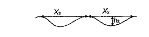
本発明者らは、上記表面が骨芽細胞分化及び骨前駆体物質の分泌を促進することを見出した。微細構造は、細胞培養皿に似た孔状のピットを含む下に横たわる微細粗さを与え、そのピットは増殖したり分化したりする細胞を刺激する。おそらく、微細構造及び一次ナノ構造を含む表面トポグラフィーは、骨吸収が起こっている生体骨における部位のトポグラフィーに類似している。本発明の部材の表面トポグラフィーは、インプラント部位の周りに存在する前骨芽細胞の期待に合い、そして骨の再モデリングに対する破骨細胞によって作成された自然の骨の表面を模倣することによって、骨芽細胞活性が本発明に記載の部材によって迅速にかつ強力に誘導され得ると考えられる。微細構造は、0.5から15μmの範囲内の、好ましくは1から10μmの範囲内のピット直径;0.1から2.5μmの範囲内の、そして好ましくは0.1から1μmの範囲内の深さを有してよい。隣接する微細ピットの間の距離は最大で10μmまであり得る。一次ナノ構造の窪みは10nmから1μmの範囲内の、好ましくは10nmから600nmの範囲内の、そしてより好ましくは10nmから500nmの範囲内の直径を有する。深さは10nmから300nm、そして一般的には30から150nmであり得る。更に、一次ナノ構造の個々の窪みの直径は、一般的には同じ個々の窪みの深さを超える。 The inventors have found that the surface promotes osteoblast differentiation and secretion of bone precursor material. The microstructure provides an underlying fine roughness containing pore-like pits resembling a cell culture dish, which stimulates cells to grow and differentiate. Presumably, surface topography, including microstructure and primary nanostructure, is similar to the topography of a site in living bone where bone resorption occurs. The surface topography of the members of the present invention meets the expectations of pre-osteoblasts present around the implant site and mimics the natural bone surface created by osteoclasts for bone remodeling, It is believed that osteoblast activity can be induced rapidly and strongly by the members described in the present invention. The microstructure has a pit diameter in the range of 0.5 to 15 μm, preferably in the range of 1 to 10 μm; in the range of 0.1 to 2.5 μm, and preferably in the range of 0.1 to 1 μm It may have a depth. The distance between adjacent fine pits can be up to 10 μm. The depression of the primary nanostructure has a diameter in the range of 10 nm to 1 μm, preferably in the range of 10 nm to 600 nm, and more preferably in the range of 10 nm to 500 nm. The depth can be from 10 nm to 300 nm, and generally from 30 to 150 nm. Furthermore, the diameter of the individual depressions of the primary nanostructure generally exceeds the depth of the same individual depression.
上記の如く、一次ナノ構造は一次微細構造上に重なる。更に、一次ナノ構造の直径及び深さは、各々、微細構造上の個々のピットの対応する寸法よりも小さい。このように、微細構造の個々のピットは一般的には一次ナノ構造の多数の窪みを含む。更に、一次ナノ構造の窪みの境界は、一般的には一次ナノ構造の他の窪みの境界の部分を構成する。 As described above, the primary nanostructure overlaps the primary microstructure. Furthermore, the diameter and depth of the primary nanostructure are each smaller than the corresponding dimension of the individual pits on the microstructure. Thus, each microstructured pit typically includes a number of depressions of the primary nanostructure. Furthermore, the depression boundaries of the primary nanostructure generally constitute part of the other depression boundaries of the primary nanostructure.
更に、上記表面は一様に分布したパターンで該一次ナノ構造の上に重なっている分離したナノ要素を含み、そして丸みのある突起の形状を有する第二ナノ要素を含み得る。第二ナノ要素は、下に横たわる表面への細胞の接着性を改善し、そしてさらに細胞活性を刺激すると考えられる。 In addition, the surface includes discrete nanoelements overlying the primary nanostructure in a uniformly distributed pattern and may include second nanoelements having a rounded protrusion shape. The second nanoelement is believed to improve cell adhesion to the underlying surface and further stimulate cellular activity.
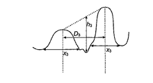
本発明の生体適合性部材の二次ナノ構造は、20から550nm、好ましくは20から150nmの範囲内のピーク直径;及び5から200nm、好ましくは5から100nmの範囲内の平均ピーク高さを有し得る。ピーク間距離は一般的には10から450nmの範囲内、好ましくは40から200nmの範囲内である。ピーク密度は一般的には、15から150ピーク/平方μmの範囲内の、そして好ましくは50から130ピーク/平方μmの範囲内である。 The secondary nanostructure of the biocompatible member of the present invention has a peak diameter in the range of 20 to 550 nm, preferably 20 to 150 nm; and an average peak height in the range of 5 to 200 nm, preferably 5 to 100 nm. Can do. The peak-to-peak distance is generally in the range of 10 to 450 nm, preferably in the range of 40 to 200 nm. The peak density is generally in the range of 15 to 150 peaks / square μm, and preferably in the range of 50 to 130 peaks / square μm.
一般に、骨組織−骨インプラントの界面で、コラーゲン及びミネラルの含有量が低下した組織層が形成されるため、正常で健康な骨と比べて低下した強度しか有しない結果となる。この組織層の厚みが、骨−インプラント界面の機械的強度を決定する(Albrektsson,
T ら、「Ultrastructural analysis of the interface zone of titanium and gold implants」、Advances in Biomaterials 4, 167-177, 1982; Albrektsson, Tら,「Interface analysis of titanium and zirconium bone implants」、Biomaterials 6, 97-101, 1985; Albrektsson T, Hansson, H-A,「An ultrastructural characterization of the interface between bone and sputtered titanium or stainless steel surfaces」、Biomaterials 7, 201-205, 1986; Hansson, H-A ら、「Structural aspects of the interface between tissue and titanium implants」、Journal of Prosthetic Dentistry 50, 108-113, 1983; Johansson, C ら、「Ultrastructural differences of the interface zone between bone and Ti6A14V or commercially pure titanium」、Journal of Biomedical Engineering 11, 3-8, 1989; Johansson, C. ら、「Qualitative, interfacial study between bone and tantalum, niobium or commercially pure titanium」、Biomaterials 11, 277-280, 1990; Sennerby, L ら、「Structure of the bone-titanium interface in retrieved clinical oral implants」、Clinical Oral Implants Research 2, 103-111, 1991; Sennerby, L ら、「Ultrastructure of the bone-titanium interface in rabits」、Journal of Materials Science: Material in Medicine 3, 262-271, 1992; Sennerby,
L ら、「Early tissue response to titanium implants inserted in rabit cortical bone, Part II: Ultrastructural observations」、Journal of Materials Science: Material in Medicine 4, 494-502, 1993)。微細構造及び一次ナノ構造を含む階層的表面トポグラフィーによって、部材と引続いて形成される骨組織との間の改善された機械的相互作用が与えられ、その結果、強度が低下したより薄い組織層が形成されると考えられる。二次ナノ構造によって、埋め込み後の生体適合性部材と周囲の骨組織間の機械的相互作用が更に改善される。従って、本発明の生体適合性部材によって、改善されたせん断強さ及び引張り強さを有する骨組織−インプラント界面が供される。
In general, a tissue layer with reduced collagen and mineral content is formed at the bone tissue-bone implant interface, resulting in a reduced strength compared to normal healthy bone. The thickness of this tissue layer determines the mechanical strength of the bone-implant interface (Albrektsson,
T et al., `` Ultrastructural analysis of the interface zone of titanium and gold implants '', Advances in Biomaterials 4, 167-177, 1982; Albrektsson, T et al., `` Interface analysis of titanium and zirconium bone implants '',
L et al., “Early tissue response to titanium implants inserted in rabbit cortical bone, Part II: Ultrastructural observations”, Journal of Materials Science: Material in Medicine 4, 494-502, 1993). Hierarchical surface topography involving microstructures and primary nanostructures provides improved mechanical interaction between the member and the subsequently formed bone tissue, resulting in thinner tissue with reduced strength It is believed that a layer is formed. Secondary nanostructures further improve the mechanical interaction between the biocompatible member after implantation and the surrounding bone tissue. Thus, the biocompatible member of the present invention provides a bone tissue-implant interface having improved shear and tensile strength.
更に、望ましい初期表面の粗さ又は望ましい化学的特性を有する部材を提供するために、基体が機械的及び/又は化学的表面処理にかけられる。化学的処理は例えば洗浄処理を含み得る。ブラスチングのような粗くする処理によって、引続いて形成される微細構造の直径及び深さが、及び一次ナノ構造の直径の変動が、より少ない(つまり、より小さな標準偏差値を有する)表面構造が与えられ得る。本発明の部材の表面の等質性(homogeneousness)の増加によって、成分のオッセオインテグレーションが更に向上し、そしてその生体力学的性質が改善する。 Further, the substrate is subjected to mechanical and / or chemical surface treatments to provide a member having the desired initial surface roughness or desirable chemical properties. The chemical treatment can include, for example, a cleaning treatment. A roughening process such as blasting results in a surface structure in which the diameter and depth of the subsequently formed microstructure and the diameter of the primary nanostructure are less (ie, have a smaller standard deviation value). Can be given. The increase in homogeneity of the surface of the component of the invention further improves the osseointegration of the components and improves its biomechanical properties.
生体適合性部材基体は一般的には少なくとも部分的にチタン又はチタン合金から成る。好ましくは、基体はチタンから成る。更に、二次ナノ構造は金属酸化物、好ましくは酸化チタンを含み得る。金属酸化物のみから成り得る部材表面の等質性は、埋め込み後の部材の長期安定性及び完全性に関して非常に有利である。加えるに、部材の表面構造は、滅菌手順及び貯蔵保管に関して安定である。 The biocompatible member substrate is generally at least partially composed of titanium or a titanium alloy. Preferably, the substrate is made of titanium. Furthermore, the secondary nanostructure may comprise a metal oxide, preferably titanium oxide. The homogeneity of the part surface, which can consist solely of metal oxides, is very advantageous with regard to the long-term stability and integrity of the part after implantation. In addition, the surface structure of the member is stable with respect to sterilization procedures and storage.
更に、部材表面に骨成長増強物質を含有させることによって本発明の成分のオッセオインテグレーションを増強し得る。そのような表面は、例えば、金属イオン例えばチタンイオン、マグネシウムイオン、カルシウムイオン、リチウムイオン、ストロンチウムイオン、又はそれらの任意の組合せから成るグループから選ばれるものをその表面に含有させることによって達成され得る。特に、本発明者らは、骨組織中に局所的に投与されたリチウムイオン又はストロンチウムイオンが該骨組織における骨成長及び骨量に対する局所的効果を有し得ることを見出した。従って、本発明の部材の表面はリチウム及び/又はストロンチウム又はその塩を含み得る。 Furthermore, the osseointegration of the component of the present invention can be enhanced by including a bone growth enhancing substance on the surface of the member. Such a surface can be achieved, for example, by including on the surface a metal ion such as selected from the group consisting of titanium ions, magnesium ions, calcium ions, lithium ions, strontium ions, or any combination thereof. . In particular, the inventors have found that lithium ions or strontium ions locally administered into bone tissue can have a local effect on bone growth and bone mass in the bone tissue. Therefore, the surface of the member of the present invention may contain lithium and / or strontium or a salt thereof.
本発明の生体適合性部材は歯科用部材、例えば、インプラント、固定具、橋脚歯、又はワンピースインプラントのようなそれらの組合せであり得る。本発明の生体適合性部材は、患者の大腿骨の頸部内への埋め込みを目的とする股関節部材のような整形外科用成分でもあり得る。 The biocompatible member of the present invention can be a dental member, such as an implant, a fixture, an abutment, or a combination thereof such as a one-piece implant. The biocompatible member of the present invention may also be an orthopedic component such as a hip member intended for implantation in the neck of a patient's femur.
別の側面において、本発明は生体適合性部材をヒト又は動物の体内にインプラントする方法であって、以下の工程:
i)上記記載の生体適合性部材を備えること;及び
ii)該生体適合性部材をヒト又は動物の体にインプラントすること;
を含むインプラント方法に関する。
In another aspect, the invention is a method of implanting a biocompatible member into a human or animal body, comprising the following steps:
i) comprising a biocompatible member as described above; and ii) implanting the biocompatible member into a human or animal body;
The present invention relates to an implant method including:
例えば、部材は前記ヒト又は動物の体の歯周領域内にインプラントされ得る。 For example, the member can be implanted in the periodontal region of the human or animal body.
本明細書で使用されるように、用語「生体適合性部材」は、生きた組織に長期間又は短期間接触することが意図され、そして該接触の際に、組織の有意な有害生体反応を引き起さない、任意の成分を、その範囲内に含む。生体適合性部材の一例は歯科用のインプラントのようなインプラントである。 As used herein, the term “biocompatible member” is intended to contact live tissue for a long or short period of time, and upon such contact, the tissue exhibits a significant adverse biological reaction. Any component that does not cause is included within the scope. An example of a biocompatible member is an implant such as a dental implant.
本明細書で使用されるように、用語「インプラント」は、その少なくともその一部が脊椎動物、特にヒトのような哺乳類の体内にインプラントされることが意図された、任意デバイスを、その範囲内に含む。インプラントは、体の解剖学的構造を代替するために及び/又は体の任意の機能を修復するために使用され得る。 As used herein, the term “implant” includes within its scope any device intended to be implanted at least in part in the body of a vertebrate, particularly a mammal such as a human. Included. Implants can be used to replace body anatomy and / or to repair any function of the body.
一般に、インプラントは1つ又は幾つかのインプラント部分から構成される。例えば、歯科用インプラントは通常、橋脚歯及び/又は修復歯のような二次的インプラント部分と結合している歯科用固定具を含む。しかしながら、埋め込みを目的とする歯科用固定具のような任意のデバイスは、他の部分がそこに結合されることになる場合であっても、単独でインプラントという場合がある。 In general, an implant consists of one or several implant parts. For example, a dental implant typically includes a dental fixture that is coupled to a secondary implant portion such as an abutment and / or a restoration tooth. However, any device, such as a dental fixture intended for implantation, may be referred to alone as an implant, even if other parts are to be coupled thereto.
本明細書で使用されるように、用語「不動態化(金属)酸化物」は、自然酸化物ともいわれる、自然に形成された酸化物のことをいい、これは時間が経っても安定で実質的により厚く成長しない、そして下に横たわる基体の、外部試薬との如何なる実質的な化学反応をも防ぐ。大気中の酸素と接触してチタン上で形成される不動態化酸化チタンは一般に2〜5nmの厚みを有する。 As used herein, the term “passivated (metal) oxide” refers to a naturally formed oxide, also referred to as a native oxide, which is stable over time. It does not grow substantially thicker and prevents any substantial chemical reaction of the underlying substrate with external reagents. Passivated titanium oxide formed on titanium in contact with atmospheric oxygen generally has a thickness of 2-5 nm.
本明細書で使用されるように、用語「骨成長増強物質」は、単独で又は他の物質との組合せで骨形成を促進できる(例えば、骨芽細胞又は前骨芽細胞の接着、増殖及び分化を促進できる;骨マトリックス成分の生成、骨マトリックス成分の分泌、骨マトリックスの石灰化を促進できる;そして破骨細胞活性を抑制できる)如何なる物質も、その範囲内に含む。 As used herein, the term “bone growth-enhancing substance” can promote bone formation alone or in combination with other substances (eg, osteoblast or pre-osteoblast adhesion, proliferation and Any substance that can promote differentiation; generation of bone matrix components, secretion of bone matrix components, calcification of bone matrix; and suppression of osteoclast activity are included within the scope.
本明細書で使用されるように、用語「微細構造」は、一般に0.5μmから100μmの範囲に及ぶ寸法の物理的構造を称し、そして用語「ナノ構造」は、一般に0.1nmから500nmの範囲に及ぶ寸法の物理的構造を称する。 As used herein, the term “microstructure” generally refers to physical structures with dimensions ranging from 0.5 μm to 100 μm, and the term “nanostructure” generally refers to 0.1 nm to 500 nm. Refers to a physical structure with dimensions that span a range.
本発明の生体適合性部材は、歯科用成分、例えば、インプラント、固定具、橋脚歯、又はワンピースインプラントのようなそれらの組合せであってよい。生体適合性部材は、患者の大腿骨の頸部内への埋め込みを目的とする股関節部材のような整形外科部材であってもよい。 The biocompatible member of the present invention may be a dental component, for example, an implant, a fixture, an abutment, or a combination thereof such as a one-piece implant. The biocompatible member may be an orthopedic member such as a hip member intended for implantation in the neck of the patient's femur.
本発明の生体適合性部材は、金属、例えば、チタン又はその合金、ジルコニウム又はその合金、ハフニウム又はその合金、ニオブ又はその合金、タンタル又はその合金、クロム−バナジウム合金、又はこれらの材料の如何なる組合せの金属、又は非金属体のような如何なる適切な材料から成り得る。生体適合性部材は、金属層、例えば非金属体または部分的に非金属材料から成る物体を被覆する塗布された金属表面層を備えていてもよい。非金属材料の例にはセラミック、プラスチック及び複合材料が挙げられる。 The biocompatible member of the present invention is a metal, such as titanium or an alloy thereof, zirconium or an alloy thereof, hafnium or an alloy thereof, niobium or an alloy thereof, tantalum or an alloy thereof, chromium-vanadium alloy, or any combination of these materials. Any suitable material, such as any metal or non-metal body. The biocompatible member may comprise a metal layer, for example an applied metal surface layer that covers a non-metallic body or an object that is partly composed of a non-metallic material. Examples of non-metallic materials include ceramics, plastics and composite materials.
金属酸化物は自然に空気で形成された酸化物であってもよく、又はそれは本発明の方法の前に如何なる種類の処理において形成されてもよい。 The metal oxide may be an oxide formed naturally in air, or it may be formed in any type of treatment prior to the method of the present invention.
生体適合性部材は、本発明の方法の更なる改質のための所望の基体表面を作出するために、如何なる種類の前処理にかけられてもよい。例えば、所望の初期表面組成又は粗さを得るために、本部材は機械的、化学的又は熱的処理、又はそれらの任意の組合せによって前処理されてもよい。機械的処理は、例えば、ブラスチング処理を含む。化学的処理は、例えば、洗浄又は脱脂処理を含む。 The biocompatible member may be subjected to any type of pretreatment to create the desired substrate surface for further modification of the method of the present invention. For example, the member may be pretreated by mechanical, chemical or thermal treatment, or any combination thereof to obtain the desired initial surface composition or roughness. The mechanical process includes, for example, a blasting process. The chemical treatment includes, for example, cleaning or degreasing treatment.
1つの側面において、本発明は生体適合性部材の改質方法に関する。 In one aspect, the present invention relates to a method for modifying a biocompatible member.
本発明の方法に従えば、生体適合性部材の少なくとも一部が、シュウ酸を含む水性組成物での処理にかけられ、そのことによって改質された金属酸化物が得られる(工程bと称される)。この処理において、改質された金属酸化物が溶かされ、そして下に横たわる基体がエッチングされ、一方で新しい酸化物が生体適合性部材上に形成される。酸化物の溶解及再酸化プロセスは同時に起こる。 According to the method of the present invention, at least a portion of the biocompatible member is subjected to treatment with an aqueous composition comprising oxalic acid, thereby obtaining a modified metal oxide (referred to as step b). ) In this process, the modified metal oxide is dissolved and the underlying substrate is etched while a new oxide is formed on the biocompatible member. The oxide dissolution and reoxidation processes occur simultaneously.
処理される生体適合性部材の部分は、前記金属酸化物によって少なくとも部分的に被覆される。本発明の実施態様において、工程bは、高温で、一定時間激しく撹拌しながら、シュウ酸の水溶液中に部材を置くことによって実行される。 The portion of the biocompatible member to be treated is at least partially coated with the metal oxide. In an embodiment of the present invention, step b is performed by placing the member in an aqueous solution of oxalic acid at high temperature with vigorous stirring for a period of time.
あるいは、部材の一部のみをこの組成物中に浸漬、例えば、ディッピングしてもよい。処理されることを意図しない成分の一部は処理の間マスキングされてもよい。 Alternatively, only a portion of the member may be dipped, eg, dipped, into the composition. Some of the components that are not intended to be processed may be masked during processing.
工程bの組成物のpHは、pH5又はそれより下、pH2又はそれより下、又はpH0.7又はそれより下のような酸性であるべきである。処理の便利さの観点から、pHはできるだけ低いことが好ましい。
The pH of the composition of step b should be acidic, such as
シュウ酸を含む水性組成物は、約0.001から約5Mの範囲内の濃度でシュウ酸を含む水溶液、例えば、該範囲内の濃度でのシュウ酸の溶液であってよい。好ましくは、組成物中のシュウ酸の濃度は、0.01から2Mの範囲内、より好ましくは0.1から2Mの範囲内、そして最も好ましくは約1Mである。 The aqueous composition containing oxalic acid may be an aqueous solution containing oxalic acid at a concentration in the range of about 0.001 to about 5M, for example, a solution of oxalic acid at a concentration in the range. Preferably, the concentration of oxalic acid in the composition is in the range of 0.01 to 2M, more preferably in the range of 0.1 to 2M, and most preferably about 1M.
工程bの目的のために、生体適合性部材の少なくとも一部を、シュウ酸を含む組成物中に約5から約60分の範囲内で、例えば20から40分の一定時間、浸漬させてもよい。一般的には、工程bの処理時間は約25分から約30分である。工程bの処理は、シュウ酸を含む水性組成物から部材が取り出された時点で完了したものとされる。 For the purpose of step b, at least a portion of the biocompatible member may be immersed in the composition comprising oxalic acid within a range of about 5 to about 60 minutes, for example 20 to 40 minutes. Good. Generally, the processing time for step b is about 25 minutes to about 30 minutes. The treatment of step b is completed when the member is taken out from the aqueous composition containing oxalic acid.
水性組成物の温度は、約20℃から約100℃の範囲内であってもよい。一般的には、シュウ酸を含む水性組成物の温度は、60℃から90℃の範囲内、例えば約80℃であってもよい。 The temperature of the aqueous composition may be in the range of about 20 ° C to about 100 ° C. In general, the temperature of the aqueous composition containing oxalic acid may be in the range of 60 ° C to 90 ° C, such as about 80 ° C.
例として、工程bの処理は80℃の温度で30分間、約1Mのシュウ酸濃度を用いて行われてよい。 As an example, the treatment of step b may be performed at a temperature of 80 ° C. for 30 minutes using an oxalic acid concentration of about 1M.
チタン部材が使用される場合、工程bで得られた改質された酸化物は、空気中で形成された不動態化酸化チタンよりもより反応性があり、そしてそれは空気中で形成された不動態化酸化チタンよりもより高い水分含量を有する。おそらく、本発明の改質された酸化チタンは、空気中で形成された又は化学的洗浄前処理において形成された不動態化酸化チタンよりもより非晶質である。工程bで得られた改質された酸化物の表面構造は微細構造及び一次ナノ構造を含み、その例が図5及び6に示されており、そしてそれについて以下により詳細に述べる。 If a titanium member is used, the modified oxide obtained in step b is more reactive than the passivated titanium oxide formed in air, and it is less reactive formed in air. It has a higher moisture content than mobilized titanium oxide. Presumably, the modified titanium oxide of the present invention is more amorphous than the passivated titanium oxide formed in air or formed in a chemical cleaning pretreatment. The surface structure of the modified oxide obtained in step b includes microstructures and primary nanostructures, examples of which are shown in FIGS. 5 and 6 and are described in more detail below.
工程bで得られた生体適合性部材の表面は、本発明の方法に記載の処理前の部材の表面の金属的な灰色よりもより明るく光沢が少ない色を有する。 The surface of the biocompatible member obtained in step b has a brighter and less glossy color than the metallic gray of the surface of the untreated member described in the method of the invention.
しかしながら、ブラスチングによって前処理された本発明の部材、及び単純に機械加工された本発明の部材の間には色の違いがあり、ブラスチングされた部材は、機械加工された部材よりも白っぽい色を有する。この変色は、工程bが完了した指標として使用され得る。しかしながら、この変色は、超音波浴中での洗浄の2分後により明瞭に見られる。 However, there is a color difference between the parts of the invention pre-processed by blasting and the parts of the invention that are simply machined, and the blasted parts have a whitish color than the machined parts. Have. This discoloration can be used as an indicator that step b has been completed. However, this discoloration is more clearly seen after 2 minutes of washing in the ultrasonic bath.
工程bに続いて、改質された酸化物の少なくとも一部分が、イオン化されたフッ素及びイオン化された塩素及び少なくとも1つの酸から成るグループから選ばれた少なくとも1つの物質を含む第二の水性組成物を用いた処理にかけられ得る(「工程c」と称する)。工程cによって、工程bにおいて形成された改質された金属酸化物の部分が溶け、そして引続いて沈殿して、該微細構造及び一次ナノ構造の上に重なっている均一に分布した金属酸化物の丸みのある突起を含む二次ナノ構造が形成される。代替として、溶けている金属酸化物の金属と複合体を形成する任意の他の化合物を使用し得る。フッ素と塩素はチタン錯化剤と知られている。 Subsequent to step b, a second aqueous composition wherein at least a portion of the modified oxide comprises at least one material selected from the group consisting of ionized fluorine and ionized chlorine and at least one acid. (Referred to as “step c”). Step c causes the portion of the modified metal oxide formed in step b to melt and subsequently precipitate to uniformly distribute the metal oxide overlying the microstructure and primary nanostructure Secondary nanostructures containing rounded protrusions are formed. Alternatively, any other compound that forms a complex with the metal of the molten metal oxide may be used. Fluorine and chlorine are known as titanium complexing agents.
部材が通常の大気圧で、そして空気のような酸素含有大気中、少なくとも0℃の温度に保持される場合、工程cは、工程bの完了後、比較的に短期間内で実行されるべきである。工程bは、工程bの水性組成物から部材が取り出されるや否や完了したものとされる。より詳しくは、工程cは、工程bにおいて得られる改質された金属酸化物が、その上に形成される不動態化酸化物によって覆われる前に実行されるべきである。不動態化酸化物は、それが、下に横たわる材料と、外部試薬との如何なる実質的な化学反応をも防ぐときに形成されるものとされる。工程bにおいて得られる改質された酸化物の反応性は、二次ナノ構造の丸みのあるピークの均一な分布を達成するために極めて重要である。工程cの処理の間、多数の活性部位で改質された酸化物を酸が攻撃し、酸化物を溶解すると考えられる。このプロセスにおいて発生した水素ガスによって、各活性部位で局所的にpHが高くなる。水性組成物が十分に高い濃度の金属材料を有していることを条件として、局所的に上昇したpHによって金属酸化物の活性部位での沈殿が引き起こされる。工程bにおいて得られる改質された酸化チタンの溶解によって酸化チタンが沈殿するのに十分に高いチタン濃度が得られ得る。酸素の存在下で時間とともに次第に不動態化酸化物が形成するので、部材が通常の大気圧で、そして酸素含有大気中少なくとも0℃の温度、例えば室温(15から25℃)に保持される場合、工程b及び工程cの間のより短い時間間隔で工程cの最終結果が改善されるであろう。このように、そのような条件下で、工程b及び工程cの間の間隔は、好ましくは出来るだけ短く保持される。工程cは工程bの完了後、180時間以内までに、例えば工程bの後72時間、36時間、24時間、又は1時間以内に実行され得る。好ましくは、工程cは工程bの完了後、30分又はそれより短い時間以内で、より好ましくは、10分又はそれより短い時間以内で実行され、そして最も好ましくは工程bの完了後、3分又はそれより短い時間以内で実行される。しかしながら、もし部材が不活性雰囲気に保持されるならば、又はさもなければ不動態化酸化物表面の形成が防がれるならば、工程b及び工程cの間の時間間隔はかなり長くてもよい。不動態化酸化物の形成を避けるために、通常の空気に比べて反応性酸素の量が低下した如何なる雰囲気も使用し得る。例えば、工程bに続いて、窒素、ヘリウム、ネオン、アルゴン、クリプトン、キセノン又はラドンのような不活性ガス中に部材を置いてもよい。あるいは、部材を減圧下の雰囲気中に又は真空中においてもよい。あるいは、部材を冷却又は冷凍してもよい。不動態化酸化物の形成を部分的に又は完全に抑制するための上記戦略の如何なる組合せもまた使用し得る。例えば、部材を工程bにかけ、引続いて冷凍し又は不活性ガス中に長時間置き、そして次に酸素含有雰囲気における通常の条件(通常の大気圧下で少なくとも0℃の温度)に戻してもよい。そのような場合、酸素含有雰囲気における該通常条件下に部材が過ごした、工程b及び工程cの間の時間は、180時間又はそれより少なく、例えば、72時間又はそれより少なく、36時間又はそれより少なく、24時間又はそれより少なく、1時間又はそれより少なく、30分又はそれより少なく、10分又はそれより少なく、又は3分又はそれより少なくすべきである。 If the member is held at normal atmospheric pressure and in an oxygen-containing atmosphere such as air at a temperature of at least 0 ° C., step c should be performed within a relatively short period of time after completion of step b. It is. Step b is completed as soon as the member is removed from the aqueous composition of step b. More particularly, step c should be performed before the modified metal oxide obtained in step b is covered by the passivating oxide formed thereon. A passivating oxide is to be formed when it prevents any substantial chemical reaction between the underlying material and an external reagent. The reactivity of the modified oxide obtained in step b is extremely important to achieve a uniform distribution of rounded peaks of secondary nanostructures. During the process of step c, it is believed that the acid attacks the oxide modified at multiple active sites and dissolves the oxide. The hydrogen gas generated in this process locally increases the pH at each active site. Provided that the aqueous composition has a sufficiently high concentration of metallic material, the locally elevated pH causes precipitation at the active site of the metal oxide. A sufficiently high titanium concentration can be obtained for the titanium oxide to precipitate by dissolution of the modified titanium oxide obtained in step b. Passive oxides gradually form over time in the presence of oxygen, so that the member is kept at normal atmospheric pressure and at a temperature of at least 0 ° C., eg room temperature (15-25 ° C.) in an oxygen-containing atmosphere. In a shorter time interval between step b and step c, the final result of step c will be improved. Thus, under such conditions, the spacing between steps b and c is preferably kept as short as possible. Step c can be performed within 180 hours after completion of step b, for example, within 72 hours, 36 hours, 24 hours, or 1 hour after step b. Preferably, step c is performed within 30 minutes or less after completion of step b, more preferably within 10 minutes or less, and most preferably 3 minutes after completion of step b. Or, it is executed within a shorter time. However, the time interval between step b and step c may be quite long if the member is maintained in an inert atmosphere or otherwise the formation of a passivating oxide surface is prevented. . Any atmosphere with a reduced amount of reactive oxygen compared to normal air may be used to avoid the formation of passivating oxides. For example, following step b, the member may be placed in an inert gas such as nitrogen, helium, neon, argon, krypton, xenon or radon. Alternatively, the member may be in an atmosphere under reduced pressure or in a vacuum. Alternatively, the member may be cooled or frozen. Any combination of the above strategies to partially or completely inhibit the formation of passivating oxides can also be used. For example, the part may be subjected to step b, subsequently frozen or placed in an inert gas for a long time, and then returned to normal conditions in an oxygen-containing atmosphere (temperature of at least 0 ° C. under normal atmospheric pressure). Good. In such cases, the time between step b and step c that the member spent under the normal conditions in an oxygen-containing atmosphere is 180 hours or less, such as 72 hours or less, 36 hours or less Should be less, 24 hours or less, 1 hour or less, 30 minutes or less, 10 minutes or less, or 3 minutes or less.
本発明の実施態様において、フッ化水素酸を含む水溶液中に成分を浸漬することによって工程cが実行される。あるいは、成分の一部のみをこの組成物中に浸漬、例えば、ディッピングしてもよい。処理されることを意図しない成分の一部は処理の間マスキングされてもよい。 In an embodiment of the present invention, step c is performed by immersing the component in an aqueous solution containing hydrofluoric acid. Alternatively, only a portion of the components may be dipped, eg, dipped, into the composition. Some of the components that are not intended to be processed may be masked during processing.
水性組成物は、イオン化されたフッ素及びイオン化された塩素及び少なくとも1つの酸を含むグループから選ばれる少なくとも1つの物質を含む。水性組成物は、0.5から5の範囲内の、好ましくは1から3の範囲内の、より好ましくは約2のpHを有する水溶液であってよい。イオン化されたフッ素及び塩素の濃度は約0.05から0.5Mの範囲内であってよい。例えば、組成物は該範囲内の濃度を有するフッ化水素酸(HF)の溶液であってよい。好ましくは、約0.1から0.3Mの範囲内、そしてより好ましくは0.1Mのフッ化水素酸の濃度が使用される。 The aqueous composition comprises at least one material selected from the group comprising ionized fluorine and ionized chlorine and at least one acid. The aqueous composition may be an aqueous solution having a pH in the range of 0.5 to 5, preferably in the range of 1 to 3, more preferably about 2. The concentration of ionized fluorine and chlorine may be in the range of about 0.05 to 0.5M. For example, the composition may be a solution of hydrofluoric acid (HF) having a concentration within the range. Preferably, a concentration of hydrofluoric acid in the range of about 0.1 to 0.3M, and more preferably 0.1M is used.
工程cの処理は、酸が基体表面上で作用するのが観察された時に開始されるものとされる。この作用は成分表面での水素ガスの形成によって検出でき、それは通常、室温で約20〜30秒後に起こる。このように、用語「積極的処理」は、水素ガスの最初の気泡の形成で開始され、実行される処理を意味する。工程cの積極的処理時間は、10秒から3分まで、10秒から2分まで、10から60秒まで、10から50秒まで、10から40秒まで、そして10から30秒までのような、10秒から60分までの範囲内である。 The treatment in step c is started when the acid is observed to act on the substrate surface. This effect can be detected by the formation of hydrogen gas at the component surface, which usually occurs after about 20-30 seconds at room temperature. Thus, the term “aggressive process” refers to a process that is initiated and carried out with the formation of an initial bubble of hydrogen gas. The active processing time of step c is from 10 seconds to 3 minutes, from 10 seconds to 2 minutes, from 10 to 60 seconds, from 10 to 50 seconds, from 10 to 40 seconds, and from 10 to 30 seconds Within 10 seconds to 60 minutes.
工程cは周囲温度で実行され得る。一般的には、工程cの水性組成物は15から25℃の範囲内の温度、例えば18から23℃の範囲内の温度を有する。 Step c can be performed at ambient temperature. Generally, the aqueous composition of step c has a temperature in the range of 15 to 25 ° C, such as a temperature in the range of 18 to 23 ° C.
例として、工程cの処理は、室温で約0.1Mの濃度のフッ化水素酸を用いて40秒の積極的処理時間で実行され得る。 As an example, the process of step c can be carried out with an active process time of 40 seconds using hydrofluoric acid at a concentration of about 0.1 M at room temperature.
許容できる結果を得るために、処理時間、温度、pH及び濃度のパラメーターの任意の1つの調整に、該パラメーターの任意の他の1つの上述の範囲で適切な調整を必要とすることが正しく理解されるであろう。 In order to obtain acceptable results, it is correctly understood that any one of the parameters of processing time, temperature, pH and concentration requires an appropriate adjustment within the above mentioned range of any other one of the parameters. Will be done.
工程cによって、工程bにおいて得られる階層的表面構造は、そのより細かな構造は部分的に溶解され得るものの、一般に保持される。工程cの後に得られる表面構造が図8及び9に示されており、そして以下により詳細に述べられる。本発明の実施態様において、工程bによって得られる改質された金属酸化物の溶解に由来する金属酸化物は、沈殿して、微細構造及び一次ナノ構造の頂部上に一様に分布した丸みのあるピークを含む二次ナノ構造を形成する。本発明の実施態様において、二次ナノ構造のピークはこのように金属酸化物から成る。工程cの組成物の金属濃度を増加させるために、工程cの水性組成物に、可溶性の金属化合物が別途に添加されてもよい。 By step c, the hierarchical surface structure obtained in step b is generally retained, although its finer structure can be partially dissolved. The surface structure obtained after step c is shown in FIGS. 8 and 9 and is described in more detail below. In an embodiment of the present invention, the metal oxide resulting from the dissolution of the modified metal oxide obtained by step b is precipitated and rounded uniformly distributed on top of the microstructure and primary nanostructure. A secondary nanostructure containing a certain peak is formed. In an embodiment of the invention, the secondary nanostructure peak thus consists of a metal oxide. In order to increase the metal concentration of the composition of step c, a soluble metal compound may be separately added to the aqueous composition of step c.
場合により、工程b及び工程cにおいて使用される組成物は、骨成長増強物質を含んでもよい。骨成長増強物質はチタンイオン、マグネシウムイオン、カルシウムイオン、リチウムイオン、及び/又はストロンチウムイオンのような金属イオン、又はそれらの塩を含んでもよい。これらのイオンは組成物に別々に添加されてもよい。例えば、工程bの組成物又は工程cの組成物のどちらかが如何なる上記金属イオンをも含んでもよい。あるいは、両方の組成物が金属イオンを含んでもよい。両方の組成物が金属イオンを含む時、それらは同じ種又は異なる種の金属イオンを含んでもよい。上記金属イオン又はそれらの如何なる組合せをも組込むことによって、化学的性質が変わった該イオン及び/又はそれらの塩を含む改質された表面が得られ得る。このように、部材の生体適合性が改善され得て、そして部材のオッセオインテグレーションが刺激され得る。 Optionally, the composition used in step b and step c may include a bone growth enhancing substance. The bone growth enhancing material may include metal ions such as titanium ions, magnesium ions, calcium ions, lithium ions, and / or strontium ions, or salts thereof. These ions may be added separately to the composition. For example, either the composition of step b or the composition of step c may contain any of the above metal ions. Alternatively, both compositions may contain metal ions. When both compositions contain metal ions, they may contain the same or different species of metal ions. By incorporating the metal ions or any combination thereof, a modified surface containing the ions and / or their salts with altered chemistry can be obtained. In this way, the biocompatibility of the member can be improved and the osseointegration of the member can be stimulated.
特に、本発明者らは、骨組織中に局所的に投与されたリチウム又はストロンチウムイオンが、該骨組織における骨形成及び骨量に対する局所効果を有することを見出した。更に、見出されたことは、イオン化されたリチウム又はストロンチウムを含有し及び/又は放出する表面を含むインプラントが、例えばイオン化されたカルシウム又はマグネシウムを含有する表面酸化物を含むインプラントと比べて、改善された骨成長速度、そしてその結果、骨組織及びインプラントの間の改善された固着速度を与えることである。従って、本発明の実施態様において、工程b及び工程cの組成物の両者又は工程b組成物のみが、イオン化されたリチウム又はストロンチウム又はその組合せを含む。あるいは、工程c組成物のみがイオン化されたリチウム又はストロンチウム又はその組合せを含む。 In particular, the inventors have found that lithium or strontium ions locally administered into bone tissue have a local effect on bone formation and bone mass in the bone tissue. Furthermore, it has been found that implants containing surfaces containing and / or releasing ionized lithium or strontium are improved compared to implants containing surface oxides containing, for example, ionized calcium or magnesium. To provide an improved bone growth rate and, consequently, an improved fixation rate between the bone tissue and the implant. Thus, in an embodiment of the present invention, both the step b and step c compositions or only the step b composition comprises ionized lithium or strontium or a combination thereof. Alternatively, only the step c composition comprises ionized lithium or strontium or a combination thereof.
あるいは、イオン化されたリチウム又はストロンチウムのような骨成長増強物質が、本発明の工程b又は工程cの実行の後で部材の表面上に塗布され得る。 Alternatively, a bone growth enhancing material such as ionized lithium or strontium can be applied onto the surface of the member after performing step b or step c of the present invention.
別の側面において、本発明は上述の方法によって得ることができる生体適合性部材、及び生体適合性部材をヒト又は動物の体内にインプラントする方法に関する。例えば、生体適合性部材がヒト又は動物の該体の歯周領域内にインプラントされ得る。 In another aspect, the present invention relates to a biocompatible member obtainable by the method described above and a method for implanting a biocompatible member into a human or animal body. For example, a biocompatible member can be implanted in the periodontal region of the human or animal body.
別の側面において、本発明は微細構造、該微細構造の上に重なる一次ナノ構造、及び場合により、該一次ナノ構造の上に重なる二次ナノ構造を含む階層的表面構造を有する生体適合性部材に関する。 In another aspect, the invention provides a biocompatible member having a microstructure, a primary nanostructure overlying the microstructure, and optionally a hierarchical surface structure comprising secondary nanostructures overlying the primary nanostructure. About.
微細構造のプロファイルに関する用語「深さ」(h1)、「直径」(x1)及び「距離」(D1)は、図1に定義されている。ピットの深さ(h1)は、二つの隣接ピークの間に引かれた仮想直線、及びその最低点での中間表面の間の距離として定義される。もし、明確に定義されたピークが存在しない場合は、表面プロファイルが、本質的に平らな表面プロファイル(プラトー)からずれ始めるそれらの点の間に仮想直線が引かれる。ピットの直径(x1)及び隣接ピットの間の距離(D1)は、図1において定義された通りの前記隣接点の間の距離である。図1においては、重なった一次ナノ構造も微細構造上に模式的に与えられている。一次ナノ構造に関する用語「深さ」(h2)及び「直径」(x2)は、図2において対応して定義される。 The terms “depth” (h 1 ), “diameter” (x 1 ) and “distance” (D 1 ) for the microstructure profile are defined in FIG. The pit depth (h 1 ) is defined as the distance between an imaginary line drawn between two adjacent peaks and the intermediate surface at its lowest point. If there are no well-defined peaks, a virtual straight line is drawn between those points where the surface profile begins to deviate from an essentially flat surface profile (plateau). The pit diameter (x 1 ) and the distance between adjacent pits (D 1 ) are the distances between the adjacent points as defined in FIG. In FIG. 1, the overlapping primary nanostructures are also schematically given on the microstructure. The terms “depth” (h 2 ) and “diameter” (x 2 ) for primary nanostructures are defined correspondingly in FIG.
二次ナノ構造に関する用語「高さ」(h3)「直径」(x3)及び「ピーク−ピーク距離」は、図3に定義される。ピーク高さは、二つの隣接ピークの間に引かれた仮想直線、及びその最低点での中間表面の間の距離として定義される。ピーク直径(x3)は、表面プロファイルが、本質的に平らな表面プロファイルからずれ始めるピークのそれらの点の間で測定される。 The terms “height” (h 3 ) “diameter” (x 3 ) and “peak-peak distance” for secondary nanostructures are defined in FIG. Peak height is defined as the distance between an imaginary line drawn between two adjacent peaks and the intermediate surface at its lowest point. The peak diameter (x 3 ) is measured between those points of the peak where the surface profile begins to deviate from the essentially flat surface profile.
図4において、微細構造のプロファイルに関する角度α、及び一次ナノ構造のプロファイルに関する角度βが定義されている。角度αは二つの仮想直線の間の角度として定義され、その中の1つの線は、表面プロファイルが、本質的に平らな表面プロファイル(P1a)からずれ始める点での微細構造のピットの壁のスロープを表し、もう一方の線は、表面プロファイルが、本質的に平らな表面プロファイル(P1b)からずれ始める点での微細構造の隣接ピットの隣接壁のスロープを表す。互いに隣接する該ピットはこのようにプラトーによって分離され得る。従って、二つの隣接ピットがピークによって分離される場合、仮想直線は、該ピークでの壁の傾斜を表す。角度βは、一次ナノ構造上の窪みの壁のその変曲点(P2a)でのスロープ、及び一次ナノ構造の隣接窪みの隣接壁のその変曲点(P2b)でのスロープを各々表す二つの仮想直線の間の角度として定義される。二つのへこんだ窪みがピークによって分離されている場合、変曲点はこのように該ピークに位置する。 In FIG. 4, an angle α related to the microstructure profile and an angle β related to the primary nanostructure profile are defined. The angle α is defined as the angle between two imaginary lines, one of which is the microstructured pit wall at the point where the surface profile begins to deviate from the essentially flat surface profile (P 1a ) The other line represents the slope of the adjacent wall of the microstructured adjacent pit at the point where the surface profile begins to deviate from the essentially flat surface profile (P 1b ). The pits adjacent to each other can thus be separated by a plateau. Thus, if two adjacent pits are separated by a peak, the virtual straight line represents the slope of the wall at that peak. The angle β represents the slope at the inflection point (P 2a ) of the wall of the depression on the primary nanostructure and the slope at the inflection point (P 2b ) of the adjacent wall of the neighboring depression of the primary nanostructure, respectively. It is defined as the angle between two virtual lines. If two indentations are separated by a peak, the inflection point is thus located at that peak.
本発明の部材の微細構造及び一次ナノ構造は、上述の方法の工程bにおいて本質的に得られる。上述の通り、工程bは厚くなった、反応性のそして白い又は白っぽい色を有する改質された酸化物表面を与える。図5aは、本発明の方法の工程bの後の成分のSEM画像であり、前記微細構造及び前記一次ナノ構造を示している。本部材はブラスチングによって前処理された。この画像において見られるように、微細構造は異なるサイズの孔状窪み又はピットを含む。図5bは本発明に記載の工程bの後の部材のSEM画像であり、ここで微細構造の幾つかのピットの直径に印が付けられている。 The microstructure and primary nanostructure of the member of the present invention is essentially obtained in step b of the method described above. As described above, step b provides a modified oxide surface with a thickened, reactive and white or whitish color. FIG. 5a is an SEM image of the component after step b of the method of the present invention, showing the microstructure and the primary nanostructure. The member was pretreated by blasting. As can be seen in this image, the microstructure contains different sized hole-like depressions or pits. FIG. 5b is an SEM image of the member after step b according to the present invention, where the diameters of several pits of the microstructure are marked.
図13及び14は微細構造のピットの直径、ピットの深さ及び互いに隣接するピットの間の距離の分布を示す。例えば、微細構造のピットは0.5から15μm、好ましくは1から10μm、そしてより好ましくは1から5μmの範囲内の直径x1;及び0.1から2.5μm、好ましくは0.1から1μm、そしてより好ましくは0.1から0.7μmの範囲内の深さh1を有し得る。隣接ピットは一般的に10μmまで、好ましくは5μmまでそしてより好ましくは3μmまでの直径を有し得るプラトー又はリッジによって分離される。このように、隣接ピット間の距離D1は、10μmまで、5μmまで又は3μmまでであり得る。しかしながら、分離するリッジを伴う場合にしばしば見られるように、二つの隣接ピットは、如何なる距離によっても全く分離されていないとされる場合がある。 FIGS. 13 and 14 show the distribution of microstructure pit diameter, pit depth and distance between adjacent pits. For example, microstructured pits have a diameter x 1 in the range of 0.5 to 15 μm, preferably 1 to 10 μm, and more preferably 1 to 5 μm; and 0.1 to 2.5 μm, preferably 0.1 to 1 μm And more preferably a depth h 1 in the range of 0.1 to 0.7 μm. Adjacent pits are generally separated by a plateau or ridge that may have a diameter of up to 10 μm, preferably up to 5 μm and more preferably up to 3 μm. Thus, the distance D 1 between adjacent pits can be up to 10 μm, up to 5 μm or up to 3 μm. However, as often seen with a separating ridge, two adjacent pits may be considered not separated at all by any distance.
図5において見られるように、微細構造の個々のピットの略形状は大まかには円形又は楕円形であってよく、又はそれが不規則であってもよい。微細構造はアンダーカットも含み得る。更に、より大きな直径のピットは、より小さな直径の1つの又は幾つかのピットを含み得る。 As can be seen in FIG. 5, the approximate shape of the individual pits of the microstructure can be roughly circular or elliptical, or it can be irregular. The microstructure can also include undercuts. Furthermore, the larger diameter pits may include one or several pits of smaller diameter.
微細構造は、上記及び図4において定義されたように、20度から130度;好ましくは30度から120度、より好ましくは40度から110度、そして最も好ましくは50度から100度の範囲内の角度αを有し得る。 The microstructure is within the range of 20 to 130 degrees; preferably 30 to 120 degrees, more preferably 40 to 110 degrees, and most preferably 50 to 100 degrees as defined above and in FIG. Of the angle α.
上述の微細構造の上に、重なった一次ナノ構造が与えられる。一次ナノ構造は図5において見られ、そして図6において更に説明されており、ここで一次ナノ構造の要素に印が付けられている。一次ナノ構造は、波状の連続構造として記載され得る。一次ナノ構造は、微細構造のピットの壁及び底において、そして微細構造のピットを分離しているプラトー及び/又はリッジにおいて、多数の浅い窪みを含む。一次ナノ構造の窪みの直径X2は10nmから1μm、好ましくは10nmから600nm、そしてより好ましくは10nmから500nmの範囲内であってよく;一次ナノ構造の窪みの深さh2は10から300nm、好ましくは30から150nmの範囲内にあってよい。一般的には、窪みは浅く、それは窪みの直径が深さを超えていることを意味する。一次ナノ構造の窪みは本質的に円形又は楕円形を有する。図15及び16は一次ナノ構造の窪みの直径と深さの分布を示す。 An overlaid primary nanostructure is provided on top of the microstructure described above. The primary nanostructure is seen in FIG. 5 and is further illustrated in FIG. 6, where the elements of the primary nanostructure are marked. Primary nanostructures can be described as wavy continuous structures. The primary nanostructure includes a number of shallow depressions at the walls and bottom of the microstructured pits and at the plateau and / or ridge separating the microstructured pits. The primary nanostructure well diameter X 2 may be in the range of 10 nm to 1 μm, preferably 10 nm to 600 nm, and more preferably 10 nm to 500 nm; the depth of primary nanostructure wells h 2 is 10 to 300 nm, Preferably it may be in the range of 30 to 150 nm. In general, the depressions are shallow, which means that the depression diameter exceeds the depth. The depression of the primary nanostructure has an essentially circular or elliptical shape. Figures 15 and 16 show the diameter and depth distribution of the depressions of the primary nanostructure.
一次ナノ構造の窪みは明確な境界又はリッジを有し得る。しかしながら、一次ナノ構造の窪みは、該窪みの底から立ち上がり、そして次にそれらの間に明確な境界を形成することなく、次の窪み内へと柔らかく通過する壁を有してもよい。しかしながら、上述の両方の場合の何れかにおいて、一次ナノ構造のある窪みの境界を他の窪みの境界から分離する定義可能な距離は存在しない。むしろ、窪みは並列しており、極めて規則的な様相を有する波状パターンを形成する。一次ナノ構造は上述の及び図4において定義されたように80度から160度;好ましくは90度から150度;より好ましくは100度から140度;そして最も好ましくは110度から130度の範囲内の角度βを有してよい。 The depression of the primary nanostructure can have a well-defined boundary or ridge. However, the depressions in the primary nanostructure may have walls that rise from the bottom of the depressions and then pass softly into the next depression without forming a clear boundary between them. However, in either of the above cases, there is no definable distance separating the boundary of one well of the primary nanostructure from the boundary of another. Rather, the depressions are side-by-side, forming a wavy pattern with a very regular appearance. The primary nanostructure is within the range of 80 to 160 degrees; preferably 90 to 150 degrees; more preferably 100 to 140 degrees; and most preferably 110 to 130 degrees as defined above and in FIG. The angle β may be
上述の如く、一次ナノ構造は一次微細構造上に重なっている。更に、一次ナノ構造の直径及び深さは、微細構造の個々のピットの各々対応する寸法よりも小さい。このように、微細構造の個々のピットは一般的には一次ナノ構造の多くの窪みを含む。例えば、微細構造のピットは約5から約50個の該窪みを含んでもよい。更に、一次ナノ構造の窪みの境界の一部が、一般的には一次ナノ構造の他の窪みの境界の一部を構成する。 As described above, the primary nanostructures overlap on the primary microstructure. Furthermore, the diameter and depth of the primary nanostructure is smaller than the corresponding dimension of each individual pit of the microstructure. Thus, individual microstructured pits typically include many depressions of primary nanostructures. For example, a microstructured pit may include about 5 to about 50 such depressions. In addition, a portion of the primary nanostructure pit boundary generally constitutes a part of the other pit boundary of the primary nanostructure.
図8及び図9は、本発明の改質された成分のSEM画像である。図8においては、サンプルがブラスチングによって前処理されたが、一方図9においては、サンプルが単純に機械加工された。これらの図において、上述の微細構造及び一次ナノ構造の上に重なった二次ナノ構造を見ることができる。図10は原子間力顕微鏡(AFM)によって撮られた画像であり、二次ナノ構造を更に示している。図10において見られる通り、二次ナノ構造は丸みのあるピークの形状を有する分離した突起要素を含む。ナノピークは下に横たわる表面構造上に密集して且つ一様に分布している。例えば、単位面積当りのピーク数は15から150ピーク/平方μm、そして好ましくは50から130ピーク/平方μmの範囲内であってよい。 8 and 9 are SEM images of the modified components of the present invention. In FIG. 8, the sample was pre-processed by blasting, whereas in FIG. 9, the sample was simply machined. In these figures, a secondary nanostructure can be seen overlying the microstructure and primary nanostructure described above. FIG. 10 is an image taken with an atomic force microscope (AFM), further illustrating the secondary nanostructure. As can be seen in FIG. 10, the secondary nanostructure includes discrete protruding elements having a rounded peak shape. The nanopeaks are densely and uniformly distributed on the underlying surface structure. For example, the number of peaks per unit area may be in the range of 15 to 150 peaks / square μm, and preferably 50 to 130 peaks / square μm.
図17は二次ナノ構造ピークの直径、平均ピーク高さ及びピーク−ピーク距離の分布を示すグラフである。一般的には、二次ナノ構造の平均ピーク高さh3は5から200nm、好ましくは5から100nmの範囲内である。二次ナノ構造の個々のピークの直径×3は一般的には、20から550nmの、好ましくは20から150nmの範囲内である。ピーク−ピーク距離D3は一般的には、10から450nm、好ましくは40から200nmの範囲内である。図11は、微細構造、一次ナノ構造及び二次ナノ構造を含む成分のSEM画像を示し、ここでは微細構造のピットに印が付けられていている。 FIG. 17 is a graph showing the distribution of secondary nanostructure peak diameter, average peak height and peak-peak distance. In general, the average peak height h 3 of the secondary nanostructure is in the range of 5 to 200 nm, preferably 5 to 100 nm. The diameter x 3 of the individual peaks of the secondary nanostructure is generally in the range of 20 to 550 nm, preferably 20 to 150 nm. Peak - The peak distance D 3 typically, 450 nm to 10, preferably in the range from 40 to 200 nm. FIG. 11 shows an SEM image of the component comprising the microstructure, primary nanostructure and secondary nanostructure, where the microstructured pits are marked.
本発明の部材がシュウ酸処理の前にブラスチングにかけられた本発明の実施態様においては、その上に微細構造が重ねられる優れた表面構造が存在する。ブラスチングによって前処理された本発明の部材の表面構造は、一般的には、10から70μmの範囲内の長さ及び3から20μmの範囲内の深さを有する大きなピットを含む。一般的には、これらの大きなピットは略楕円形を有する。隣接するピット間の距離は1から20μmの範囲内である。この大きなピット構造の上に重なって、上記の微細構造がある。このように、大きなピットの側部及び底部並びに大きなピットの間の表面は、ピット及び上述の微細構造の分離しているプラトー及び/又はリッジを含む。従来のブラスチングされた面のSEM画像が図7に示されている。ブラスチング前処理は、引続いて形成された微細構造、一次ナノ構造及び場合により二次ナノ構造の寸法に影響を及ぼす。ブラスチングにかけられた本発明に記載の部材において、引続いて形成された微細構造は、単純に機械加工された本発明に記載の部材の微細構造よりも幾分より大きな寸法を一般的に有しており、そして引続いて形成された一次ナノ構造は、単純に機械加工された本発明に記載の部材の一次ナノ構造よりも幾分より小さな寸法を一般的に有していた。加えて、微細構造及び一次ナノ構造の両者の直径、及び微細構造の深さは、表1に示された標準偏差値によって説明されている通り、機械加工された部材の対応する特性よりも、ブラスチングされた部材において、より一様であった。 In the embodiment of the present invention in which the member of the present invention is blasted prior to the oxalic acid treatment, there is an excellent surface structure on which the microstructure is superimposed. The surface structure of the member of the invention pretreated by blasting generally comprises large pits having a length in the range of 10 to 70 μm and a depth in the range of 3 to 20 μm. In general, these large pits have a substantially elliptical shape. The distance between adjacent pits is in the range of 1 to 20 μm. Overlying this large pit structure is the fine structure described above. Thus, the sides and bottom of the large pits and the surface between the large pits include the pits and the above-described microstructured separating plateaus and / or ridges. A SEM image of a conventional blasted surface is shown in FIG. The blasting pretreatment affects the dimensions of subsequently formed microstructures, primary nanostructures and possibly secondary nanostructures. In a member according to the invention that has been subjected to blasting, the subsequently formed microstructure generally has a somewhat larger dimension than the microstructure of the member according to the invention that has been simply machined. And subsequently formed primary nanostructures generally had somewhat smaller dimensions than the primary nanostructures of the simply described machined members of the present invention. In addition, the diameter of both the microstructure and the primary nanostructure, and the depth of the microstructure, as illustrated by the standard deviation values shown in Table 1, are more than the corresponding properties of the machined member. More uniform in blasted parts.
別の側面において、本発明は生体適合性部材をヒト又は動物の体内にインプラントする方法に関する。本方法は、i)上記に記載の生体適合性部材を供する;及びii)該生体適合性部材をヒト又は動物の体にインプラントする;工程を含む。例えば、生体適合性部材が前記ヒト又は動物の体の歯周領域内にインプラントされ得る。 In another aspect, the invention relates to a method of implanting a biocompatible member into a human or animal body. The method comprises the steps of i) providing a biocompatible member as described above; and ii) implanting the biocompatible member into a human or animal body; For example, a biocompatible member can be implanted in the periodontal region of the human or animal body.
実施例
実施例 1−表面改質
(i)サンプル調製
コインの形状を有するチタンサンプル(各々機械加工されたものとブラスチングされたもの)、固定具(ブラスチングされたもの)及び橋脚歯(機械加工されたもの)を従来の化学的処理によって洗浄した。これらのサンプルを1Mのシュウ酸水溶液中に浸漬し、そして80℃で30分間、激しい撹拌下に置いた。30分後シュウ酸水溶液から、サンプルを取出して水中でゆすぎ、続いて超音波浴中の水中で2分間、ゆすいだ。ゆすぎの約10分後、サンプルを0.1Mのフッ化水素酸(HF)水溶液中に室温で浸漬し、活発な溶解が始まるまで撹拌し、引続いて追加の活性化処理を40秒間行った。次に、HF溶液からサンプルを取出して水中でゆすぎ、引き続いて超音波浴中の水中で5分間、ゆすいだ。これらのサンプルを、滅菌前に室温で空気中において約60分間、乾燥した。
Examples Example 1-Surface Modification (i) Sample Preparation Titanium samples with coin shape (each machined and blasted), fixtures (blasted) and abutments (machined) Were washed by conventional chemical treatment. These samples were immersed in 1M aqueous oxalic acid solution and placed under vigorous stirring at 80 ° C. for 30 minutes. After 30 minutes, the sample was removed from the aqueous oxalic acid solution and rinsed in water, followed by 2 minutes in water in an ultrasonic bath. About 10 minutes after rinsing, the sample was immersed in 0.1 M aqueous hydrofluoric acid (HF) solution at room temperature and stirred until active dissolution began, followed by an additional activation treatment for 40 seconds. . The sample was then removed from the HF solution and rinsed in water followed by a 5 minute rinse in water in an ultrasonic bath. These samples were dried in air at room temperature for approximately 60 minutes before sterilization.
(ii)表面トポロジー測定
ESEM XL30(FEI)を用いて、工程bに続いてゆすいだ後のサンプル及び工程cに続いて乾燥した後のサンプルについて走査型電子顕微鏡(SEM)観察を実施した。500×及び15000×の間の倍率を用いて、立体画像を撮影し、そしてMeX 5.0 programme(Alicona)によって評価した。フィルターは使用しなかった。微細構造のピット及び一次ナノ構造の窪みの深さ及び直径、並びに及び微細構造の隣接ピットの間の距離を求めた。結果を一次微細構造に対して図13a−c(機械加工されたサンプル)、及び図14a−c(ブラスチングされたサンプル)、そして一次ナノ構造に対して図15a−b(機械加工されたサンプル)、及び図16a−b(ブラスチングされたサンプル)に提示する。滅菌後に撮られたSEM画像を図8、9及び11に提示する。
(Ii) Surface topology measurement
Using ESEM XL30 (FEI), scanning electron microscope (SEM) observation was performed on the sample after rinsing following step b and the sample after drying following step c. Stereoscopic images were taken using magnifications between 500x and 15000x and evaluated by the MeX 5.0 program (Alicona). No filter was used. The depth and diameter of the microstructured pits and primary nanostructure depressions, and the distance between adjacent microstructured pits were determined. The results are shown in FIGS. 13a-c (machined sample) and FIGS. 14a-c (blasted sample) for the primary microstructure and FIGS. 15a-b (machined sample) for the primary nanostructure. , And FIGS. 16a-b (blasted samples). SEM images taken after sterilization are presented in FIGS.
Nanoscope IIIa instrument(Digital Instruments)を用いて、TappingMode(商標)原子間力顕微鏡(AFM)観察を実施した。本発明に記載の(機械加工された)三つのサンプルの二次ナノ構造を、一サンプルにつき二点で解析した:各点はサンプル端部から約1ミリメーターに位置していた。解析面積は2μm×2μmであった。ピーク高さ、ピーク直径、ピーク−ピーク距離及び平方μm当たりのピーク数を求めた。該寸法はミリメーターで測定し、そして得られたプロファイルプロット中に供されたスケールを用いてnmに変換した。ピーク高さ、ピーク直径、ピーク−ピーク距離の各々の分布を図17a−cに提示する。 TappingMode (trademark) atomic force microscope (AFM) observation was performed using Nanoscope IIIa instrument (Digital Instruments). Three sample (machined) secondary nanostructures according to the present invention were analyzed at two points per sample: each point was located approximately 1 millimeter from the sample edge. The analysis area was 2 μm × 2 μm. Peak height, peak diameter, peak-peak distance, and number of peaks per square μm were determined. The dimensions were measured in millimeters and converted to nm using the scale provided in the resulting profile plot. The respective distributions of peak height, peak diameter, and peak-peak distance are presented in FIGS. 17a-c.
表1に、SEM/MeX5.0によって求めた、ブラスチングした成分及び機械加工した成分の各々の微細構造及び一次ナノ構造に対して求めた寸法の最大値、最小値及び平均値を纏めてある。機械加工された成分の二次ナノ構造に対して、AFMによって求めた最大値、最小値及び平均値も提示してある。 Table 1 summarizes the maximum, minimum and average dimensions determined for the microstructure and primary nanostructure of each of the blasted and machined components as determined by SEM / MeX5.0. The maximum, minimum and average values determined by AFM for the secondary nanostructure of the machined component are also presented.

比較例1a
(コインの形状をした)ブラスチング処理されたチタンサンプルを、0.1Mのフッ化水素酸及び1Mのシュウ酸を含む水溶液中に室温で浸漬し、そして各々、5、15、30及び42分間、撹拌した。溶液から、サンプルを取出して水中でゆすぎ、続いて超音波浴中の水中で2分間、ゆすいだ。サンプルを乾燥後、走査型電子顕微鏡(ESEM XL30、FEI)によって表面トポグラフィーを調べた。
Comparative Example 1a
The blasted titanium sample (in the shape of a coin) is immersed in an aqueous solution containing 0.1 M hydrofluoric acid and 1 M oxalic acid at room temperature and for 5, 15, 30 and 42 minutes, respectively. Stir. A sample was removed from the solution and rinsed in water, followed by a 2 minute rinse in water in an ultrasonic bath. After the sample was dried, the surface topography was examined with a scanning electron microscope (ESEM XL30, FEI).
その結果、上記処理を5分間行った場合、部分的にエッチングされた領域、そして一様でなく分布した突起要素を有するサンプルが得られた。15分後に取出したサンプルは、まばらに突き出した要素を含む、比較的平らでエッチングされた表面構造を示した。30分後に取出したサンプルの表面は、筋状の外観を有しそして小さな突起要素及び幾つかの不定形の粒子も含んでいた。5分間、処理された乾燥サンプルのSEM画像を図12aに提示し、そして30分間、処理された乾燥サンプルのSEM画像を図12bに提示する。 As a result, when the above treatment was performed for 5 minutes, a sample having partially etched regions and unevenly distributed protrusion elements was obtained. Samples taken after 15 minutes showed a relatively flat and etched surface structure containing sparsely protruding elements. The surface of the sample taken after 30 minutes had a streaked appearance and also contained small protruding elements and some irregular particles. A SEM image of the dried sample processed for 5 minutes is presented in FIG. 12a and a SEM image of the dried sample processed for 30 minutes is presented in FIG. 12b.
比較例1b
チタンサンプルを0.1MのHF水溶液中に室温で浸漬し、そして活発な溶解が始まるまで撹拌し、続いて40秒の追加の処理時間をかけた。次いでHF溶液から、サンプルを取出して水中でゆすぎ、続いて超音波浴中の水中で5分間、ゆすいだ。ゆすぎの約10分後、サンプルを1Mのシュウ酸水溶液中に浸漬し、80℃で30分間、激しく撹拌した。30分後、シュウ酸溶液からサンプルを取出して水中でゆすぎ、引き続いて超音波浴中の水中で2分間、ゆすいだ。これらのサンプルを、室温で1時間、乾燥させた。
Comparative Example 1b
The titanium sample was immersed in a 0.1 M aqueous HF solution at room temperature and stirred until active dissolution began, followed by an additional treatment time of 40 seconds. The sample was then removed from the HF solution and rinsed in water, followed by a 5 minute rinse in water in an ultrasonic bath. About 10 minutes after rinsing, the sample was immersed in 1M aqueous oxalic acid solution and stirred vigorously at 80 ° C. for 30 minutes. After 30 minutes, the sample was removed from the oxalic acid solution and rinsed in water, followed by rinsing in water in an ultrasonic bath for 2 minutes. These samples were dried for 1 hour at room temperature.
走査型電子顕微鏡ESEM XL30(FEI)によって、乾燥したサンプルの画像を撮った。結果を図12cに提示する。 Images of the dried samples were taken with a scanning electron microscope ESEM XL30 (FEI). Results are presented in FIG.
実施例2−細胞増殖及び活性
細胞増殖、及びアルカリホスファターゼ(ALP)及びプロスタグラジンE2(PGE2)各々の産生を、本発明に従ってチタン表面上でインビトロで成長させたヒト骨芽細胞に対して調べ、市販のインプラント表面(OsseoSpeed(商標);Asta Tech AB、スウェーデン)上で成長させた細胞と比較した。
Example 2-Cell proliferation and activity Cell proliferation and production of alkaline phosphatase (ALP) and prostaglandin E2 (PGE2), respectively, was examined on human osteoblasts grown in vitro on titanium surfaces according to the present invention. Compared with cells grown on a commercially available implant surface (OsseoSpeed ™; Asta Tech AB, Sweden).
(i)細胞培養
MG−63は、骨芽細胞のインビトロの研究のために従来から使用されているヒト細胞株である。この研究においては、MG-63cells(MG-63、ATCC No CRL-1427、米国)を、300mLのFalcon細胞培養フラスコ(BD、WWR、スウェーデン)内の、5%のウシ胎児血清(FCS;Gibco、英国)及び1%のペニシリン−ストレプトマイシン(PEST;Gibco、英国)を含むダルベッコ最少必須培地(Dulbecco's Minimun Essential Medium(D-MEM))(Gibco、英国)中で、冷凍細胞の膨大部からの2回目の継代から、成長させた。 接着した細胞が密集度まで成長したら、0.05%トリプシン−EDTA(Gibco、英国)を用いて、それらを3継代の継代をさせた。光学顕微鏡を用いてカウントした細胞生存率は高かった(>98%)。
(I) Cell culture MG-63 is a human cell line conventionally used for in vitro studies of osteoblasts. In this study, MG-63cells (MG-63, ATCC No CRL-1427, USA) were transferred to 5% fetal calf serum (FCS; Gibco, USA) in a 300 mL Falcon cell culture flask (BD, WWR, Sweden). 2nd from a large portion of frozen cells in Dulbecco's Minimun Essential Medium (D-MEM) (Gibco, UK) containing 1% penicillin-streptomycin (PEST; Gibco, UK) It was grown from the passage. Once the adherent cells grew to confluency, they were passaged 3 passages using 0.05% trypsin-EDTA (Gibco, UK). Cell viability counted using a light microscope was high (> 98%).
(ii)細胞形態(SEM)
三つのコイン形状をした、β−滅菌されたチタン試験体;その中の1つは本発明の工程bにかけられたもの;その中の1つは本発明の工程b及び工程cにかけられたもの;そしてその中の1つは市販の表面(OsseoSpeed(商標);Asta Tech AB、スウェーデン)を有したもの;を各々別のFalcon24ウェルプレート(BD、WWR、スウェーデン)中に置いた。各々のウエルに、5%のFCS(Gibco、英国)及び1%のPEST(Gibco、英国)を含有し、20,000細胞/mLの細胞濃度を有する1mlのD−MEM(Gibco、英国)を添加した。これらのプレートを37℃、5%のCO2及び湿度100%で36時間、インキュベートした。従来のSEMサンプル調製手順に従って、サンプルを4℃でグルタルアルデヒドを用いて、続いて四酸化オスミウムによって固定し、脱水及び金スパッタリングした。細胞形態をSEM(ESEM XL30、FEI)によって調べた。細胞のSEM画像を図20a(従来の表面上で成長させた細胞)、図20b(本発明の工程bに従って処理された部材上で成長させた細胞)、図20c(本発明の工程b及び工程cに従って処理された部材上で成長させた細胞)に示す。
(Ii) Cell morphology (SEM)
Three coin-shaped, β-sterilized titanium specimens, one of which was subjected to step b of the present invention; one of which was subjected to step b and step c of the present invention One of which had a commercially available surface (OsseoSpeed ™; Asta Tech AB, Sweden); each was placed in a separate Falcon 24 well plate (BD, WWR, Sweden). Each well contains 1 ml D-MEM (Gibco, UK) containing 5% FCS (Gibco, UK) and 1% PEST (Gibco, UK) and having a cell concentration of 20,000 cells / mL. Added. The plates were incubated for 36 hours at 37 ° C., 5% CO 2 and 100% humidity. Following conventional SEM sample preparation procedures, samples were fixed with glutaraldehyde at 4 ° C. followed by osmium tetroxide, dehydrated and gold sputtered. Cell morphology was examined by SEM (ESEM XL30, FEI). FIG. 20a (cells grown on a conventional surface), FIG. 20b (cells grown on a member treated according to step b of the present invention), FIG. 20c (steps b and step of the present invention). cells grown on parts treated according to c).
(iii)細胞増殖、ALP活性及びPGE2活性の評価
三セット(n=6)のコイン形状をした、β−滅菌されたチタン試験体;一組は本発明の工程bにかけられたもの(「本発明の表面1」);一組は本発明の工程b及び工程cにかけられたもの(「本発明の表面2」);そして一組は市販の表面(OsseoSpeed(商標);Asta Tech AB、スウェーデン)を有するもの;を各々別のFalcon24ウェルプレート(BD、WWR、スウェーデン)中に置いた。各々のウエルに5%のFCS(Gibco、英国)及び1%のPEST(Gibco、英国)を含有し、そして20,000細胞/mLの細胞濃度を有する1mlのD−MEM(Gibco、英国)を添加した。これらのプレートを37℃、5%のCO2及び湿度100%で14日間インキュベートした。
(Iii) Evaluation of cell proliferation, ALP activity and PGE2 activity Three sets (n = 6) of coin-shaped, β-sterilized titanium specimens; one set subjected to step b of the present invention (
培養7日後に、各ウエルからのサンプル(50マイクロリッター)を外因的ALPに対して解析した。接着した細胞を解析して、細胞溶解によって内因的ALPを求め、続いて遠心分離し、そしてメーカーの取扱説明書に従って、SenzoLyte(商標)pNPP Alkaline Phosphatase Assay Kit Colorimetric(BioSite、スウェーデン)を用いて、上澄み液及び細胞内のALP含有量(ng/ml)を求めた。7日後に、本発明に記載の工程b及び工程cにかけられたサンプル(本発明の表面2)は、参照サンプル(OsseoSpeed(登録商標))よりも顕著に高い細胞当たりのALP産生を誘導した。結果を図19に示す。 After 7 days in culture, samples from each well (50 microliters) were analyzed for exogenous ALP. Analyzing adherent cells to determine endogenous ALP by cell lysis followed by centrifugation and using the SenzoLyte ™ pNPP Alkaline Phosphatase Assay Kit Colorimetric (BioSite, Sweden) according to the manufacturer's instructions, The supernatant and intracellular ALP content (ng / ml) were determined. After 7 days, the sample subjected to steps b and c according to the invention (surface 2 of the invention) induced significantly higher ALP production per cell than the reference sample (OsseoSpeed®). The results are shown in FIG.
培養7日後及び14日後に各々、NucleoCassette、NucleoCounter(ChemoMetec A/S、デンマーク)を用いて、メーカーの取扱説明書に従って、ウエル当たりの合計細胞数を求めた。結果を図18に提示する。 The total number of cells per well was determined after 7 and 14 days of culture using NucleoCassette and NucleoCounter (ChemoMetec A / S, Denmark), respectively, according to the manufacturer's instructions. Results are presented in FIG.
培養7日後及び14日後に各々、ELISA kit R&D Systems PGE2 Immunoassay(R&D Systems、英国)を用いて、メーカーの取扱説明書に従ってPGE2を求めるために各々のウエルから300マイクロリッターの上澄み液を使用した。培養7日後のPGE2の産生は、参照と比較して本発明に記載のサンプルにおいて若干少なかった。しかしながら、14日後では、本発明に記載のサンプルの両方のセットが、参照サンプルよりも著しく高い細胞当たりのPGE2の産生を誘導した。培養7日後及び14日後の結果を各々図21に提示する。 After 7 days and 14 days of culture, 300 microliters of supernatant from each well was used to determine PGE2 using ELISA kit R & D Systems PGE2 Immunoassay (R & D Systems, UK), respectively, according to the manufacturer's instructions. The production of PGE2 after 7 days in culture was slightly less in the samples according to the invention compared to the reference. However, after 14 days, both sets of samples according to the invention induced significantly higher production of PGE2 per cell than the reference sample. The results after 7 days and 14 days of culture are shown in FIG.
要約すると、参照表面と比較して本発明のサンプルは、より低い細胞密度及びより低い接着細胞数しか誘導しなかったことが見出された。しかしながら、参照表面上で成長した細胞と比較して本発明の表面上で成長した細胞の中で、より高い細胞数が増殖性であった。本発明の表面上で成長した細胞はまた、図20a−cにおいて見られる通り、アポートシスをより起こし難く、より長いそして多くの小さな突起を有しており、活性があることを示した。 In summary, it was found that the samples of the present invention induced only a lower cell density and a lower number of adherent cells compared to the reference surface. However, a higher number of cells was proliferative among the cells grown on the surface of the present invention compared to cells grown on the reference surface. Cells grown on the surface of the present invention also showed less activity, had longer and many smaller protrusions, and were active, as seen in FIGS. 20a-c.
本発明に記載の両方の表面上で成長した細胞は、培養14日後では、図20a−cにおいて見られる通り、従来の表面上で成長した細胞のそれと比較して、有意に増加したPGE2産生を示した。更に、二次ナノ構造を含む、本発明に記載の表面上で成長した細胞は、従来の表面上で成長した細胞よりも、有意に高いALP活性を有していた。ALP及び/又はPGE2活性の増加は、増大した骨芽細胞活性、低下した破骨細胞活性及び促進されたECMの石灰化に関係している。このように、結論として、本発明は、骨成長速度及びオッセオインテグレーションに関して改質された生体適合性部材を提供する。 Cells grown on both surfaces described in the present invention have significantly increased PGE2 production after 14 days in culture compared to that of cells grown on conventional surfaces, as seen in FIGS. 20a-c. Indicated. Furthermore, cells grown on the surface according to the present invention containing secondary nanostructures had significantly higher ALP activity than cells grown on conventional surfaces. Increased ALP and / or PGE2 activity is associated with increased osteoblast activity, decreased osteoclast activity and enhanced ECM calcification. Thus, in conclusion, the present invention provides a biocompatible member that is modified with respect to bone growth rate and osseointegration.
実施例3−埋め込み
本発明に記載のインプラントの完全性をウサギモデルにおいて試験した。その目的は、市販の参照インプラントに対する応答と比較して、本発明に記載の二つのインプラント表面改質に対するインビボの骨組織応答を定性的に及び定量的に調べることであった。
Example 3-Implant The integrity of the implant described in the present invention was tested in a rabbit model. The aim was to qualitatively and quantitatively examine the in vivo bone tissue response to the two implant surface modifications described in the present invention compared to the response to a commercially available reference implant.
(i)除去トルク試験用インプラント
シュウ酸中に、そして引き続きHF中に浸漬することによって、実施例1において述べられた通りに(つまり工程b及びcを含んで)、調製したチタントルク固定具(四角形の頭をした除去トルク設計、3.5×8.2ミリメーター)を使用した(試験インプラント2と称する)。また、シュウ酸中に浸漬することによって、実施例1において述べられた通りに(つまり工程cが省略されて)、調製したトルク固定具(3.5×8.2ミリメーター)(試験インプラント1と称する)も使用した。更に、市販のOsseoSpeed(商標)口腔インプラントを代表するトルク固定具(3.5×8.2ミリメーター)を参照固定具として使用した。
(I) Removal torque test implants Prepared titanium torque fixtures as described in Example 1 (ie including steps b and c) by immersion in oxalic acid and subsequently in HF A square-headed removal torque design (3.5 × 8.2 millimeters) was used (referred to as test implant 2). Alternatively, the prepared torque fixture (3.5 × 8.2 millimeters) (Test Implant 1) as described in Example 1 (ie, step c was omitted) by immersion in oxalic acid. Also referred to). In addition, a torque fixture (3.5 × 8.2 millimeters) representative of a commercially available OsseoSpeed ™ oral implant was used as a reference fixture.
(ii)組織学及び組織学形態計測研究用のインプラント
上記実施例1において述べられた通りに調製した口腔インプラント(3.5×8ミリメーター)のヒト設計の固定具を使用した(試験インプラント2)。また、HF処理(つまり工程c)を省略した以外は、実施例1において述べられた通りに調製した固定具(3.5×8ミリメーター)も使用した(試験インプラント1)。更に、市販のOsseoSpeed(商標)口腔インプラントを代表する固定具(3.5×8ミリメーター)を参照固定具として使用した。
(Ii) Implants for histology and histology morphometry studies Human-designed fixtures of oral implants (3.5 × 8 millimeters) prepared as described in Example 1 above were used (Test Implant 2 ). A fixture (3.5 × 8 millimeters) prepared as described in Example 1 was also used (test implant 1) except that the HF treatment (ie step c) was omitted. In addition, a fixture (3.5 × 8 millimeters) representative of a commercially available OsseoSpeed ™ oral implant was used as a reference fixture.
(iii)インプラント挿入
12把の成体の雄のニュージーランド白ウサギを手術用として予定した。一把のウサギは初期の麻酔で死んだ(#8)。手術は平穏に進んだ。連続食塩冷却を用いて、低速穴開け(穴開けのために1500rpg、そしてインプラント挿入のために20rpm)を行った。
(Iii) Implant Insertion Twelve adult male New Zealand white rabbits were scheduled for surgery. A single rabbit died in early anesthesia (# 8). The operation proceeded calmly. Slow drilling (1500 rpg for drilling and 20 rpm for implant insertion) was performed using continuous saline cooling.
1つのインプラント(口腔インプラントのヒト設計;3.5×8ミリメーター)を各々大腿軟骨領域中に挿入し、そして三つのインプラント(四角形の頭をした除去トルク設計、3.5×8.2ミリメーター)を各々脛骨粗面中に挿入した。大腿骨インプラントを組織学形態計測解析用に、そして脛骨インプラントを除去トルク試験用に予定した。 One implant (human design of oral implant; 3.5 × 8 mm) was inserted into each femoral cartilage area and three implants (square head removal torque design, 3.5 × 8.2 mm) Meter) was inserted into each rough tibial surface. The femoral implant was scheduled for histological morphometric analysis and the tibial implant for removal torque testing.
(iv)除去トルク試験
6週間後に、試験を終了し、そしてウサギを犠牲にした。インプラント及び周囲の組織を調べた。脛骨インプラントは容易に位置が分かり、それらの全てで、骨膜骨組織成長の兆候が見られた。除去トルク試験(RTQ)を用いて、インプラント−骨界面の生体力学的試験を実施した。RTQ装置(Detektor AB、Goteborg、スウェーデン)は、骨層におけるインプラントの安定性(Ncmを単位とするピークゆるみトルク)を試験するために使用される歪ゲージトランスジューサーを含む電子機器であり、従って、骨組織及びインプラントの間の界面せん断力を大まかに反映する三次元試験と見なすことができる(Johansson C. B.,Albrektsson T.,Clin Oral implants Res 1991;2:24-9)。直線的に増大するトルクがインプラントの同じ軸上に、一体化が破壊されるまでかけられ、そしてピーク値が記録された。大腿骨中に挿入されたインプラントは、よりしばしば骨組織によるインプラント頭部の「完全な被覆」を示した。大腿骨インプラントを固定液中に浸漬し、そして組織学及び組織学形態計測研究のために更に処理した。
(Iv) Removal torque test After 6 weeks, the test was terminated and the rabbits were sacrificed. The implant and surrounding tissue were examined. The tibial implants were easily located and all of them showed signs of periosteal bone tissue growth. An implant-bone interface biomechanical test was performed using a removal torque test (RTQ). The RTQ device (Detektor AB, Goteborg, Sweden) is an electronic device that includes a strain gauge transducer used to test the stability of the implant in the bone layer (peak loose torque in Ncm), and therefore It can be regarded as a three-dimensional test that roughly reflects the interfacial shear forces between bone tissue and implants (Johansson CB, Albrektsson T., Clin Oral implants Res 1991; 2: 24-9). A linearly increasing torque was applied on the same axis of the implant until the integration was broken and the peak value was recorded. Implants inserted into the femur more often “completely covered” the implant head with bone tissue. The femoral implant was immersed in fixative and further processed for histology and histology morphometry studies.
除去トルク試験用の試験インプラント1、試験インプラント2及び参照インプラントの平均値を図22に提示する。全ての試験インプラント1、試験インプラント2及び参照インプラントの比較から、参照インプラントと比較して、試験インプラント2に対する除去トルク値において25%の改善が見られた。この差異は統計的に有意であった(p<0.05; Student T−test)。更に、これらの結果は、試験インプラント1の除去トルク値が、参照インプラントのそれらと同等以上であることを示唆した。
The average values of the
(v)組織学的評価
6週間後に、試験を終了し、そしてウサギを犠牲にした。ウサギ#1及び#5からの骨組織及びインプラントを含む大腿骨インプラント部位の選択サンプルを、骨−インプラント接触(BIC)及び内側のネジ山(thread)内の骨領域(内部領域、ia)及び大腿骨から回収されたインプラント周辺の種々の領域における対応する鏡像(mi)に関して組織学形態計測的に評価した。
(V) Histological evaluation After 6 weeks, the study was terminated and the rabbits were sacrificed. Selected samples of femoral implant sites including bone tissue and implants from
インプラントの異なる領域のBIC及び骨領域に対する平均値、並びに各インプラントに対するBIC及び骨領域の総平均値を下表2及び3に報告する。下記のインプラント領域が評価された:
(a)ミクロ−ネジ山;
(b)マクロ−ネジ山;
(c)骨髄空洞における先端側(ネジ山がない)に沿った領域;及び
(d)インプラントの先端底部中(この領域は、骨インプラント接触についてのみ報告される)
The average values for the BIC and bone regions of the different areas of the implant and the total average of the BIC and bone areas for each implant are reported in Tables 2 and 3 below. The following implant areas were evaluated:
(A) Micro-threads;
(B) Macro-screw thread;
(C) the area along the distal side (no threads) in the bone marrow cavity; and (d) in the bottom of the distal end of the implant (this area is only reported for bone implant contact)
参照インプラントであるウサギ#5に対しては、全てのインプラントにおいて存在する切開部を通して断面(section)が偶然に得られた。このサンプルについて、計算された底部接触距離は、試験インプラント1であるウサギ#3のそれの合計距離の近似に基づくものであった(図24a)。
For the reference implant,
表2及び3において見ることができる通り、試験インプラント2は、参照表面と比較してより高い骨インプラント接触及びネジ山におけるより大きな骨領域を示した。試験インプラント1は、参照表面と比較してほとんど同等の骨インプラント接触を示した。また、参照インプラントのそれと比較して、ネジ山におけるより大きな内部骨領域が観察された(表2)。
As can be seen in Tables 2 and 3, test implant 2 showed higher bone implant contact and larger bone area at the screw thread compared to the reference surface.
骨形成を定性的に示す組織学的断面画像を図23〜24に提示するが、ここで;
図23aはウサギ#1、試験インプラント2を示す;
図23bはウサギ#1、参照インプラントを示す;
図24aはウサギ#5、試験インプラント1を示す;及び
図24bはウサギ#5、参照インプラントを示す;
Histological cross-sectional images qualitatively showing bone formation are presented in FIGS. 23-24, where:
Figure 23a shows
Figure 23b shows
Figure 24a shows
ほぼ全てのサンプルが、上部ミクロネジ山領域におけるインプラントに密接に関係して、古い骨よりもより新しく形成された骨を示した。骨髄空洞中及び先端底層中のインプラントのネジ山がない側におけるマクロネジ山において観察された骨組織も新しく形成された。 Almost all samples showed newer formed bones than old bones, closely related to the implant in the upper microthread region. The bone tissue observed in the macro-thread on the non-threaded side of the implant in the bone marrow cavity and in the apical floor also newly formed.
ウサギ#1において、試験インプラント2の周囲に、参照インプラントと比較して大量の進行中の骨形成が観察された。骨芽細胞の種々の形状の骨芽細胞縁を有する骨様の継ぎ目がしばしば観察された(図23a、b)。
In
ウサギ#5において、試験インプラント1の周囲に、参照インプラントと比較して大量の進行中の骨形成が観察された。骨芽細胞がしばしば観察されたが、ウサギ#1の試験インプラント2の周囲ほど顕著ではなかった(図24a、b)。
In
インプラント表面は、インプラント表面とは無関係に、骨髄空洞の脂肪細胞と密接に関連しており、感受性の骨髄細胞を有する全ての表面の高度な生体適合性を示した。 The implant surface was closely related to the bone marrow cavity adipocytes, regardless of the implant surface, and showed a high degree of biocompatibility of all surfaces with sensitive bone marrow cells.
実施例4−インビトロのアパタイト形成
骨形成を調べるための1つの従来からのインビトロのモデルは、疑似体液(SBFs)中への生体材料の浸漬である。SBFsはヒトの血漿のそれにほぼ等しいイオン濃度を有する溶液である(Kokubo T.,Kushitani H.,Sakka S.,Kitsugi T.,Yamamuro T.,J Biomed Mater Res 1990;24:721-734;Oyane A.,Kim H. K.,Furuya T.,Kokubo T.,Miyazaki T., Nakamura T.,J Biomed Mater Res 2003;65A、188-195)。生体材料の核形成能力に依存して、骨状のリン酸カルシウムがその表面上に沈殿することになる。インビボの骨生理活性を有するSBF中でのアパタイト形成の定量的相関が報告されている(Kokubo T.,Takadama H.,Biomaterials 2006;27:2907-2915)。今日では、SBFのインビトロモデルはしばしば使用され、そして国際標準、ISO 23317:2007Eによって記載されている。
Example 4-In Vitro Apatite Formation One conventional in vitro model for examining bone formation is the immersion of biomaterials in simulated body fluids (SBFs). SBFs are solutions having an ionic concentration approximately equal to that of human plasma (Kokubo T., Kushitani H., Sakka S., Kitsugi T., Yamamuro T., J Biomed Mater Res 1990; 24: 721-734; Oyane A., Kim HK, Furuya T., Kokubo T., Miyazaki T., Nakamura T., J Biomed Mater Res 2003; 65A, 188-195). Depending on the nucleation capacity of the biomaterial, bone-like calcium phosphate will precipitate on its surface. A quantitative correlation of apatite formation in SBF with bone bioactivity in vivo has been reported (Kokubo T., Takadama H., Biomaterials 2006; 27: 2907-2915). Today, in vitro models of SBF are often used and described by the international standard, ISO 23317: 2007E.
(i)SBF浸漬
ヒトの血漿の電解質濃度に類似した電解質濃度を有する修正SBF(Oyane A.ら、J Biomed Mater Res 2003;65A、188-195)が選択された(Vander A.J., Sherman J.H., Luciano D.S.,「Human physiology The mechanisms of body function)」、5th ed. McGraw-Hill Publishing Company、ニューヨーク、1990:349-400)。SBFは10.806gのNaCl、1.480gのNaHCO3、4.092gのNa2CO3、0.450gのKCl、0.460gのK2HPO4・3H2O、0.622gのMgCl2・6H2O、23.856gの2−(4−(2−ヒドロキシエチル)−1−ピペラジニル)エタンスルホン酸(HEPES)、0.776gのCaCl2及び0.144gのNa2SO4を、2000ミリリッターの脱イオン水中に溶解させることによって調製した。HEPESは溶液に添加する前に、200ミリリッターの脱イオン水中に溶解させた。最終的なpHは1.0MのNaOHを用いて37℃で7.40に調節された。全ての試薬は、NaCl及びNa2SO4 (これらはFluka(スウェーデン)から得られた)を除いて、Merck(スウェーデン)から得られた。
(I) SBF immersion Modified SBF (Oyane A. et al., J Biomed Mater Res 2003; 65A, 188-195) with an electrolyte concentration similar to that of human plasma was selected (Vander AJ, Sherman JH, Luciano DS, "Human physiology The mechanisms of body function", 5th ed. McGraw-Hill Publishing Company, New York, 1990: 349-400). SBF is 10.806 g NaCl, 1.480 g NaHCO 3 , 4.092 g Na 2 CO 3 , 0.450 g KCl, 0.460 g K 2 HPO 4 .3H 2 O, 0.622 g MgCl 2. 6 H 2 O, 23.856 g 2- (4- (2-hydroxyethyl) -1-piperazinyl) ethanesulfonic acid (HEPES), 0.776 g CaCl 2 and 0.144 g Na 2 SO 4 were Prepared by dissolving in liter of deionized water. HEPES was dissolved in 200 milliliters of deionized water before being added to the solution. The final pH was adjusted to 7.40 at 37 ° C. with 1.0 M NaOH. All reagents were obtained from Merck (Sweden) except for NaCl and Na 2 SO 4 (which were obtained from Fluka (Sweden)).
三組のコイン形状をした、β−滅菌されたチタンサンプル;一組は本発明の工程bにかけられたもの(「本発明の表面1」);一組は本発明の工程b及び工程cにかけられたもの(「本発明の表面2」);そして一組は市販の表面(OsseoSpeed(商標);Asta Tech AB、スウェーデン)を代表する参照;を別々のそして密閉された50ミリリッターのポリスチレンバイアル(VER、スウェーデン)中の37ミリリッターのSBF中に浸漬した。サンプルを、バイアルの蓋に吊り下げて搭載し、解析されるべきコインの側が、他の如何なる物体によっても接触されないで、下向きになるようにした。三日後、SBF浸漬を中断し、サンプルを脱イオン水で完全にゆすぎ、如何なるゆるく接着したリン酸カルシウム材料をも除去した。次いでサンプルを室温にて、層流空気ベンチ中で乾燥した。各組の三つのサンプルをSBF中に浸漬しないでコントロール用として役立てた。
Three sets of coin-shaped, β-sterilized titanium samples; one set subjected to step b of the present invention ("
(ii)形成されたアパタイトの形態(SEM)
可能なアパタイトの形成の解析を、環境走査型電子顕微鏡(ESEM、XL 30、FEI)を用いて実施した。SBF浸漬前の表面構造のSEM画像を、図25a(参照)、26a(本発明の表面1)、及び27a(本発明の表面2)に提示する。SBF浸漬後の表面構造を調べたとき、サンプルの全ての組上でリン酸カルシウムの薄い層が形成されたと結論付けられた;参照(図25b)、本発明の表面1(図26b)、及び本発明の表面2(図27b)。
(Ii) Form of apatite formed (SEM)
Analysis of possible apatite formation was performed using an environmental scanning electron microscope (ESEM,
(iii)形成されたアパタイトの化学的評価(EDS)
アパタイト形成前後のサンプルの化学的解析のためにエネルギー分散分光法(EDS,Apollo 40,EDAX)を使用した。チタンシグナルを解析することによって、リン酸カルシウムによるサンプルの被覆度が間接的に評価できた。本発明表面2は、SBF浸漬後のチタンシグナルにおいて最大の低下を示し(図28)、調査した資料の組の中で最も広範囲なアパタイト形成を示した。
(Iii) Chemical evaluation of the formed apatite (EDS)
Energy dispersive spectroscopy (EDS,
非晶質及び結晶性のリン酸カルシウム相対的存在量を推定するためにCa/P比の計算にEDSがやはり使用された。Ca/P比を図29に提示する。得られたCa/P比は、参照表面上よりも、本発明の表面1の上及び本発明の表面2の上に形成されたアパタイトの方のより高度の結晶性を示した。リン酸三カルシウム(Ca3(PO4)2)及びヒドロキシアパタイト(Ca5(PO4)3OH)の化学量論的Ca/P原子比は、各々1.5及び1.67であった。
EDS was also used to calculate the Ca / P ratio to estimate the relative abundance of amorphous and crystalline calcium phosphate. The Ca / P ratio is presented in FIG. The resulting Ca / P ratio showed a higher degree of crystallinity on the apatite formed on the
要約として、サンプルの全ての組で初期にアパタイト形成が見出され、本発明の表面2は、チタンシグナルによって結論付けられる通り(図28)、最高度のアパタイト被覆を示した。 In summary, apatite formation was initially found in all sets of samples and the surface 2 of the present invention showed the highest degree of apatite coating as concluded by the titanium signal (FIG. 28).
Claims (51)
a)少なくとも部分的に金属酸化物で被覆された生体適合性部材を備えること;及び
b)該部材の部分が該金属酸化物で被覆された、その部材の少なくとも一部を、シュウ酸を含む水性組成物で処理すること;そして、さらに、
c)i)イオン化されたフッ素及びイオン化された塩素を含むグループから選ばれる少なくとも1つの材料;及び
ii)少なくとも1つの酸;
を含む第二の水性組成物で、改質された金属酸化物の少なくとも部分を処理すること、ここで、改質された金属酸化物上に不動態化酸化物が形成される前に、工程cが実行されること;
を含み、そのことによって、改質された金属酸化物の部分が溶解し、そして引き続いて沈殿して金属酸化物を含む二次ナノ構造を形成する、方法。 A method for modifying a biocompatible member, comprising the following steps:
a) comprising a biocompatible member at least partially coated with a metal oxide; and b) at least a portion of the member coated with the metal oxide comprising oxalic acid. Treating with an aqueous composition; and
c) i) at least one material selected from the group comprising ionized fluorine and ionized chlorine; and
ii) at least one acid;
Treating at least a portion of the modified metal oxide with a second aqueous composition comprising a step wherein a passivating oxide is formed on the modified metal oxide. c is executed;
Wherein a portion of the modified metal oxide is dissolved and subsequently precipitated to form a secondary nanostructure comprising the metal oxide.
a)プラトー及び/又はリッジによって分離されたピットを含む微細構造;
b)該微細構造の上に重なっている一次ナノ構造、ここで該一次ナノ構造は波状の形に配置された窪みを含む;及び
c)前記一次ナノ構造の上に重なっている二次ナノ構造
を含む金属酸化物の表面を有する基体を含む生体適合性部材。 A biocompatible member at least partially coated with a metal oxide comprising:
a) a microstructure comprising pits separated by plateaus and / or ridges;
b) a primary nanostructure overlying the microstructure, wherein the primary nanostructure includes depressions arranged in a wavy shape; and c) a secondary nanostructure overlying the primary nanostructure A biocompatible member comprising a substrate having a metal oxide surface.
Applications Claiming Priority (3)
| Application Number | Priority Date | Filing Date | Title |
|---|---|---|---|
| EP07112076A EP2022447A1 (en) | 2007-07-09 | 2007-07-09 | Nanosurface |
| EP07112076.0 | 2007-07-09 | ||
| PCT/EP2008/058860 WO2009007373A1 (en) | 2007-07-09 | 2008-07-08 | Nanosurface |
Publications (3)
| Publication Number | Publication Date |
|---|---|
| JP2011509098A JP2011509098A (en) | 2011-03-24 |
| JP2011509098A5 JP2011509098A5 (en) | 2011-08-11 |
| JP5658561B2 true JP5658561B2 (en) | 2015-01-28 |
Family
ID=38740247
Family Applications (1)
| Application Number | Title | Priority Date | Filing Date |
|---|---|---|---|
| JP2010515496A Active JP5658561B2 (en) | 2007-07-09 | 2008-07-08 | Nano surface |
Country Status (12)
| Country | Link |
|---|---|
| US (2) | US8632836B2 (en) |
| EP (4) | EP2022447A1 (en) |
| JP (1) | JP5658561B2 (en) |
| KR (1) | KR20100055403A (en) |
| CN (2) | CN101686862B (en) |
| AT (1) | ATE494861T1 (en) |
| AU (1) | AU2008274303A1 (en) |
| BR (1) | BRPI0814563B8 (en) |
| CA (1) | CA2693478A1 (en) |
| DE (1) | DE602008004546D1 (en) |
| ES (3) | ES2358776T3 (en) |
| WO (1) | WO2009007373A1 (en) |
Families Citing this family (54)
| Publication number | Priority date | Publication date | Assignee | Title |
|---|---|---|---|---|
| US8403991B2 (en) | 2005-05-06 | 2013-03-26 | Titan Spine Llc | Implant with critical ratio of load bearing surface area to central opening area |
| US8480749B2 (en) | 2005-05-06 | 2013-07-09 | Titan Spine, Llc | Friction fit and vertebral endplate-preserving spinal implant |
| US8562685B2 (en) | 2005-05-06 | 2013-10-22 | Titan Spine, Llc | Spinal implant and integration plate for optimizing vertebral endplate contact load-bearing edges |
| US8435302B2 (en) | 2005-05-06 | 2013-05-07 | Titan Spine, Llc | Instruments and interbody spinal implants enhancing disc space distraction |
| US8585765B2 (en) | 2005-05-06 | 2013-11-19 | Titan Spine, Llc | Endplate-preserving spinal implant having a raised expulsion-resistant edge |
| US8591590B2 (en) | 2005-05-06 | 2013-11-26 | Titan Spine, Llc | Spinal implant having a transverse aperture |
| US8545568B2 (en) | 2005-05-06 | 2013-10-01 | Titan Spine, Llc | Method of using instruments and interbody spinal implants to enhance distraction |
| US9168147B2 (en) | 2005-05-06 | 2015-10-27 | Titan Spine, Llc | Self-deploying locking screw retention device |
| US8585767B2 (en) | 2005-05-06 | 2013-11-19 | Titan Spine, Llc | Endplate-preserving spinal implant with an integration plate having durable connectors |
| US8262737B2 (en) | 2005-05-06 | 2012-09-11 | Titan Spine, Llc | Composite interbody spinal implant having openings of predetermined size and shape |
| US8551176B2 (en) | 2005-05-06 | 2013-10-08 | Titan Spine, Llc | Spinal implant having a passage for enhancing contact between bone graft material and cortical endplate bone |
| US8585766B2 (en) | 2005-05-06 | 2013-11-19 | Titan Spine, Llc | Endplate-preserving spinal implant with an integration plate having durable connectors |
| US8617248B2 (en) | 2005-05-06 | 2013-12-31 | Titan Spine, Llc | Spinal implant having variable ratios of the integration surface area to the axial passage area |
| US8814939B2 (en) | 2005-05-06 | 2014-08-26 | Titan Spine, Llc | Implants having three distinct surfaces |
| US11096796B2 (en) | 2005-05-06 | 2021-08-24 | Titan Spine, Llc | Interbody spinal implant having a roughened surface topography on one or more internal surfaces |
| US8758442B2 (en) | 2005-05-06 | 2014-06-24 | Titan Spine, Llc | Composite implants having integration surfaces composed of a regular repeating pattern |
| US8992622B2 (en) | 2005-05-06 | 2015-03-31 | Titan Spine, Llc | Interbody spinal implant having a roughened surface topography |
| US9125756B2 (en) | 2005-05-06 | 2015-09-08 | Titan Spine, Llc | Processes for producing regular repeating patterns on surfaces of interbody devices |
| US20120312779A1 (en) | 2005-05-06 | 2012-12-13 | Titian Spine, LLC | Methods for manufacturing implants having integration surfaces |
| US8758443B2 (en) | 2005-05-06 | 2014-06-24 | Titan Spine, Llc | Implants with integration surfaces having regular repeating surface patterns |
| US8562684B2 (en) | 2005-05-06 | 2013-10-22 | Titan Spine, Llc | Endplate-preserving spinal implant with an integration plate having a roughened surface topography |
| EP2022447A1 (en) * | 2007-07-09 | 2009-02-11 | Astra Tech AB | Nanosurface |
| US8696759B2 (en) * | 2009-04-15 | 2014-04-15 | DePuy Synthes Products, LLC | Methods and devices for implants with calcium phosphate |
| EP2556528B1 (en) * | 2010-04-09 | 2018-11-07 | Brown University | Nanostructured surfaces |
| EP2394602B1 (en) * | 2010-06-10 | 2016-05-18 | Dentsply IH AB | A dental fixture |
| JP2012143416A (en) * | 2011-01-13 | 2012-08-02 | Gc Corp | Dental implant and surface treatment method of dental implant |
| KR20130032507A (en) * | 2011-09-23 | 2013-04-02 | 포항공과대학교 산학협력단 | Cross-linkable nanostructured organometallic polymers for enzymatic biofuel cell and biosensor applications |
| US8992619B2 (en) | 2011-11-01 | 2015-03-31 | Titan Spine, Llc | Microstructured implant surfaces |
| TWI469762B (en) * | 2011-11-25 | 2015-01-21 | Ind Tech Res Inst | Electrosurgical unit with micro/nano structures and the manufacturing method thereof |
| WO2013109078A1 (en) * | 2012-01-20 | 2013-07-25 | 오스템임플란트 주식회사 | Porous surface for improving the bone-fusing ability of an implant having a macro/micro/nano-scale three-part structure, and production method therefor |
| AU2013235264B2 (en) * | 2012-03-20 | 2017-09-28 | Titan Spine, Inc. | Friction-fit spinal endplate and endplate-preserving method |
| EP2716261A1 (en) | 2012-10-02 | 2014-04-09 | Titan Spine, LLC | Implants with self-deploying anchors |
| US9498349B2 (en) | 2012-10-09 | 2016-11-22 | Titan Spine, Llc | Expandable spinal implant with expansion wedge and anchor |
| US20160120625A1 (en) * | 2013-06-07 | 2016-05-05 | Straumann Holding Ag | Abutment |
| US9615935B2 (en) | 2014-01-30 | 2017-04-11 | Titan Spine, Llc | Thermally activated shape memory spring assemblies for implant expansion |
| US20170172711A1 (en) * | 2014-02-21 | 2017-06-22 | Maruemu Works Co., Ltd. | Dental member |
| US10687956B2 (en) | 2014-06-17 | 2020-06-23 | Titan Spine, Inc. | Corpectomy implants with roughened bioactive lateral surfaces |
| US20150366668A1 (en) * | 2014-06-23 | 2015-12-24 | Community Blood Center | Cellular-scale surface modification for increased osteogenic protein expression |
| CN105441960A (en) * | 2014-08-22 | 2016-03-30 | 广州中国科学院先进技术研究所 | Method for constructing micrometer/nanometer hierarchical structure with super hydrophilicity on surface of titanium dental implant |
| EP3034033A1 (en) | 2014-12-16 | 2016-06-22 | Nobel Biocare Services AG | Dental implant |
| JP6914266B2 (en) | 2015-11-20 | 2021-08-04 | タイタン スパイン インコーポレイテッドTitan Spine,Inc. | How to make additional orthopedic implants |
| TWI726940B (en) | 2015-11-20 | 2021-05-11 | 美商泰坦脊柱股份有限公司 | Processes for additively manufacturing orthopedic implants |
| CN105537589B (en) * | 2016-01-28 | 2018-12-25 | 佛山市安齿生物科技有限公司 | A kind of SLM molding surface treatment method of titanium implant |
| JP2019523092A (en) | 2016-08-03 | 2019-08-22 | タイタン スパイン インコーポレイテッドTitan Spine,Inc. | Titanium implant surface without alpha case and enhanced bone guidance |
| JP6455634B2 (en) | 2016-11-10 | 2019-01-23 | 株式会社ナントー | Method for forming living tissue survival surface, and method for producing implant |
| CN108096640A (en) * | 2016-11-24 | 2018-06-01 | 重庆润泽医药有限公司 | A kind of porous material |
| JP6893838B2 (en) * | 2017-07-12 | 2021-06-23 | 日本ピストンリング株式会社 | Implant surface structure and method of manufacturing implant surface structure |
| WO2019063711A1 (en) * | 2017-09-27 | 2019-04-04 | Straumann Holding Ag | Process for the preparation of nanostructures on a dental implant |
| GB201802109D0 (en) * | 2018-02-09 | 2018-03-28 | Depuy Ireland Ultd Co | Medical implants comprising anti-infective surfaces |
| US20200306015A1 (en) * | 2018-06-07 | 2020-10-01 | Taiwan Shan Yin International Co., Ltd. | Implant device |
| US11485052B2 (en) | 2018-07-30 | 2022-11-01 | Canon Kabushiki Kaisha | Resin product, method of making resin product, interchangeable lens, and optical device |
| JP7423202B2 (en) | 2018-07-30 | 2024-01-29 | キヤノン株式会社 | Resin products, resin product manufacturing methods, interchangeable lenses, and optical equipment |
| KR102399423B1 (en) * | 2021-03-16 | 2022-05-19 | 주식회사 도이프 | Manufacturering of orthodontic mini screw and method of surface treatment |
| EP4169485A1 (en) * | 2021-10-21 | 2023-04-26 | Anthogyr | Implant with bone anchor and method for manufacturing such an implant |
Family Cites Families (75)
| Publication number | Priority date | Publication date | Assignee | Title |
|---|---|---|---|---|
| US4015A (en) * | 1845-04-26 | Hand-loom for weaving figured fabrics | ||
| CA962806A (en) * | 1970-06-04 | 1975-02-18 | Ontario Research Foundation | Surgical prosthetic device |
| US3707006A (en) * | 1970-08-26 | 1972-12-26 | Gulf Oil Corp | Orthopedic device for repair or replacement of bone |
| US3906550A (en) * | 1973-12-27 | 1975-09-23 | William Rostoker | Prosthetic device having a porous fiber metal structure |
| US4374669A (en) * | 1975-05-09 | 1983-02-22 | Mac Gregor David C | Cardiovascular prosthetic devices and implants with porous systems |
| US4101984A (en) * | 1975-05-09 | 1978-07-25 | Macgregor David C | Cardiovascular prosthetic devices and implants with porous systems |
| SE416175B (en) * | 1979-03-07 | 1980-12-08 | Per Ingvar Branemark | FOR IMPLANTATION IN BODY TISSUE Separate Bone Tissue, Dedicated Material |
| GB2189815B (en) * | 1986-03-24 | 1990-10-10 | Permelec Electrode Ltd | Titanium composite materials coated with calcium phosphate compound and process for production thereof |
| ES2044211T3 (en) * | 1989-03-23 | 1994-01-01 | Straumann Inst Ag | METALLIC IMPLANT. |
| JPH0428374A (en) * | 1990-05-23 | 1992-01-30 | Tdk Corp | Composite implant |
| DE69022776T2 (en) | 1989-06-06 | 1996-05-30 | Tdk Corp | Use of ceramic materials as replacement materials for living tissue. |
| JP2930619B2 (en) * | 1989-10-30 | 1999-08-03 | 春幸 川原 | Titanium or titanium-based alloy biomedical restoration member and surface treatment method |
| DE4028374A1 (en) | 1990-09-07 | 1992-03-12 | Abb Patent Gmbh | Solder joining ionic conductive ceramic to non-ionic conductive ceramic - uses powdered metal oxide solder which is heated to just below its melting point and is resistant to high temps. |
| TW197475B (en) | 1990-12-26 | 1993-01-01 | Eltech Systems Corp | |
| US5282861A (en) * | 1992-03-11 | 1994-02-01 | Ultramet | Open cell tantalum structures for cancellous bone implants and cell and tissue receptors |
| US5356516A (en) | 1993-02-26 | 1994-10-18 | Sandia Corporation | Process for etching mixed metal oxides |
| US5824651A (en) | 1993-05-10 | 1998-10-20 | Universite De Montreal | Process for modification of implant surface with bioactive conjugates for improved integration |
| US5368881A (en) * | 1993-06-10 | 1994-11-29 | Depuy, Inc. | Prosthesis with highly convoluted surface |
| EP0746273B1 (en) | 1993-11-02 | 2004-02-11 | Hospital For Joint Diseases | Control of cell growth |
| US7048870B1 (en) * | 1993-12-20 | 2006-05-23 | Astrazeneca Ab | Metallic implant and process for treating a metallic implant |
| ATE274861T1 (en) * | 1994-11-30 | 2004-09-15 | Implant Innovations Inc | PREPARATION OF AN IMPLANT SURFACE |
| US6491723B1 (en) | 1996-02-27 | 2002-12-10 | Implant Innovations, Inc. | Implant surface preparation method |
| US5863201A (en) | 1994-11-30 | 1999-01-26 | Implant Innovations, Inc. | Infection-blocking dental implant |
| US6652765B1 (en) | 1994-11-30 | 2003-11-25 | Implant Innovations, Inc. | Implant surface preparation |
| DE19506188C2 (en) | 1995-02-22 | 2003-03-06 | Miladin Lazarov | Implant and its use |
| WO1997021393A1 (en) | 1995-12-08 | 1997-06-19 | Calcitek, Inc. | Dental implant having multiple tectured surfaces |
| CA2205104A1 (en) | 1996-05-10 | 1997-11-10 | Eugenia Ribeiro De Sousa Fidalgo Leitao | Device for incorporation and release of biologically active agents |
| EP0806212B1 (en) | 1996-05-10 | 2003-04-02 | IsoTis N.V. | Device for incorporation and release of biologically active agents |
| EP0806211B1 (en) | 1996-05-10 | 2002-10-23 | IsoTis N.V. | Implant material and process for producing it |
| UA53673C2 (en) | 1996-11-19 | 2003-02-17 | Александр Константиновіч Камлюк | Winch with drive from transfer box of a vehicle |
| WO1998025761A1 (en) | 1996-12-09 | 1998-06-18 | Nippon Sheet Glass Co., Ltd. | Non-fogging article and process for the production thereof |
| US20050031663A1 (en) | 1997-05-16 | 2005-02-10 | Cecilia Larsson | Implant element |
| JP3404286B2 (en) | 1998-04-16 | 2003-05-06 | 日本パーカライジング株式会社 | Metal surface treatment method, and metal member having a surface obtained by the surface treatment method |
| US6261322B1 (en) * | 1998-05-14 | 2001-07-17 | Hayes Medical, Inc. | Implant with composite coating |
| SE514202C2 (en) * | 1999-05-31 | 2001-01-22 | Nobel Biocare Ab | Layers arranged on bone or tissue structure implants and such implants and methods for applying the layer |
| TW491714B (en) * | 1999-12-08 | 2002-06-21 | Wen-Jing Shiue | Orthopedic implant having a porous surface and method of making same |
| US7048541B2 (en) | 2000-04-04 | 2006-05-23 | Nobel Biocare Ab | Implant having attachment and hole-insert parts, and method for producing such an implant |
| IT1317969B1 (en) * | 2000-06-09 | 2003-07-21 | Nora Elettrodi De | ELECTRODE CHARACTERIZED BY A HIGH ADHESION OF A SURFACE CATALYTIC LAYER. |
| CH694935A5 (en) * | 2000-07-26 | 2005-09-30 | Straumann Holding Ag | Oberflaechenmodifizierte implants. |
| IL149700A0 (en) | 2000-09-19 | 2002-11-10 | Eduardo Anitua Aldecoa | Method for surface treatment of implants or prosthesis made of titanium or other materials |
| CN1237945C (en) * | 2000-10-09 | 2006-01-25 | 刘宝林 | Improved grit-blasting treatment process for the surface of tooth implant |
| US6921544B2 (en) * | 2001-03-06 | 2005-07-26 | Rutgers, The State University | Magnesium-substituted hydroxyapatites |
| WO2002078759A1 (en) | 2001-04-02 | 2002-10-10 | Stratec Medical Ag | Bioactive surface layer, particularly for medical implants and prostheses |
| US6527938B2 (en) * | 2001-06-21 | 2003-03-04 | Syntheon, Llc | Method for microporous surface modification of implantable metallic medical articles |
| US7157096B2 (en) * | 2001-10-12 | 2007-01-02 | Inframat Corporation | Coatings, coated articles and methods of manufacture thereof |
| WO2003044383A1 (en) | 2001-11-23 | 2003-05-30 | Alcove Surfaces Gmbh | Bearing and composite structure |
| SE523288C2 (en) * | 2002-07-19 | 2004-04-06 | Astra Tech Ab | An implant and a method of treating an implant surface |
| US7537664B2 (en) * | 2002-11-08 | 2009-05-26 | Howmedica Osteonics Corp. | Laser-produced porous surface |
| EP1440669B1 (en) | 2003-01-23 | 2006-11-22 | Dinkelacker, Wolfgang, Dr. med. dent. | Bone implant and process for its manufacture |
| JP5079208B2 (en) * | 2003-02-24 | 2012-11-21 | デピュイ・プロダクツ・インコーポレイテッド | Metal implant having a rough surface and method for manufacturing the same |
| US20040167632A1 (en) | 2003-02-24 | 2004-08-26 | Depuy Products, Inc. | Metallic implants having roughened surfaces and methods for producing the same |
| EP1622629B1 (en) * | 2003-05-07 | 2013-07-10 | Osteologix A/S | Controlled-release composition containing a strontium salt |
| US8251700B2 (en) | 2003-05-16 | 2012-08-28 | Biomet 3I, Llc | Surface treatment process for implants made of titanium alloy |
| US20050119758A1 (en) | 2003-07-30 | 2005-06-02 | Bio-Lok International Inc. | Surgical implant for promotion of osseo-integration |
| DE602004029377D1 (en) * | 2004-03-04 | 2010-11-11 | Young-Taek Sul | OSSEOINDUCTIVE MAGNESIUM TITANIUM IMPLANT AND METHOD OF MANUFACTURING THEREOF |
| KR100714244B1 (en) * | 2004-04-26 | 2007-05-02 | 한국기계연구원 | Osseoinductive metal implants for a living body and producing method thereof |
| US8329202B2 (en) * | 2004-11-12 | 2012-12-11 | Depuy Products, Inc. | System and method for attaching soft tissue to an implant |
| EP1853394A4 (en) | 2005-02-24 | 2009-09-30 | Biomet 3I Llc | Surface treatment methods for implants made of titanium or titanium alloy |
| US7601149B2 (en) | 2005-03-07 | 2009-10-13 | Boston Scientific Scimed, Inc. | Apparatus for switching nominal and attenuated power between ablation probes |
| WO2006102347A2 (en) | 2005-03-21 | 2006-09-28 | The Regents Of The University Of California | Controllable nanostructuring on micro-structured surfaces |
| US7368065B2 (en) * | 2005-06-23 | 2008-05-06 | Depuy Products, Inc. | Implants with textured surface and methods for producing the same |
| JP2007001826A (en) | 2005-06-24 | 2007-01-11 | Hitachi Ltd | Metal oxide material, its producing method and its application |
| EP1764116A1 (en) * | 2005-09-16 | 2007-03-21 | Debiotech S.A. | Porous coating process using colloidal particles |
| US20090207790A1 (en) | 2005-10-27 | 2009-08-20 | Qualcomm Incorporated | Method and apparatus for settingtuneawaystatus in an open state in wireless communication system |
| ES2726355T3 (en) | 2005-11-14 | 2019-10-03 | Biomet 3I Llc | Deposition of discrete nanoparticles on an implant surface |
| US7749555B2 (en) * | 2006-01-25 | 2010-07-06 | Medtronic, Inc | Modification of chemical forces of bone constructs |
| US9327056B2 (en) * | 2006-02-14 | 2016-05-03 | Washington State University | Bone replacement materials |
| US20070264303A1 (en) * | 2006-05-12 | 2007-11-15 | Liliana Atanasoska | Coating for medical devices comprising an inorganic or ceramic oxide and a therapeutic agent |
| CA2671348A1 (en) * | 2006-12-22 | 2008-07-03 | Thommen Medical Ag | Dental implant and method for the production thereof |
| EP2022447A1 (en) * | 2007-07-09 | 2009-02-11 | Astra Tech AB | Nanosurface |
| US20090035723A1 (en) * | 2007-08-03 | 2009-02-05 | Claus Daniel | Material with a repetitive pattern of micro-features for application in a living organism and method of fabrication |
| ES2315194B1 (en) * | 2007-09-10 | 2010-02-26 | Francisco J. GARCIA SABAN | PROCEDURE TO OBTAIN A NEW SURFACE OF A METAL IMPLANT BASED ON TITANIUM INTENDED TO BE INSERTED IN OSEO FABRIC. |
| WO2009061887A2 (en) * | 2007-11-06 | 2009-05-14 | University Of Connecticut | Ceramic/structural protein composites and method of preparation thereof |
| AU2009222165B2 (en) * | 2008-02-29 | 2015-07-09 | Smith & Nephew, Inc. | Gradient coating for biomedical applications |
| US8436078B2 (en) * | 2008-04-28 | 2013-05-07 | Kuraray Noritake Dental Inc. | Dental composition and composite resin |
-
2007
- 2007-07-09 EP EP07112076A patent/EP2022447A1/en not_active Withdrawn
-
2008
- 2008-07-08 DE DE602008004546T patent/DE602008004546D1/en active Active
- 2008-07-08 KR KR1020107002403A patent/KR20100055403A/en not_active Application Discontinuation
- 2008-07-08 US US12/298,884 patent/US8632836B2/en active Active
- 2008-07-08 EP EP08774897A patent/EP2178466B1/en active Active
- 2008-07-08 AT AT08774897T patent/ATE494861T1/en active
- 2008-07-08 CN CN200880024004.6A patent/CN101686862B/en active Active
- 2008-07-08 ES ES08774897T patent/ES2358776T3/en active Active
- 2008-07-08 ES ES12179573.6T patent/ES2542243T3/en active Active
- 2008-07-08 JP JP2010515496A patent/JP5658561B2/en active Active
- 2008-07-08 EP EP10194575A patent/EP2319461B1/en active Active
- 2008-07-08 ES ES10194575T patent/ES2397633T3/en active Active
- 2008-07-08 EP EP20120179573 patent/EP2537485B1/en active Active
- 2008-07-08 BR BRPI0814563A patent/BRPI0814563B8/en active IP Right Grant
- 2008-07-08 CA CA2693478A patent/CA2693478A1/en not_active Abandoned
- 2008-07-08 CN CN201210472825.4A patent/CN102961193B/en active Active
- 2008-07-08 WO PCT/EP2008/058860 patent/WO2009007373A1/en active Application Filing
- 2008-07-08 AU AU2008274303A patent/AU2008274303A1/en not_active Abandoned
-
2012
- 2012-09-14 US US13/620,079 patent/US9642708B2/en active Active
Also Published As
| Publication number | Publication date |
|---|---|
| BRPI0814563A2 (en) | 2015-01-06 |
| EP2537485B1 (en) | 2015-05-13 |
| WO2009007373A1 (en) | 2009-01-15 |
| ES2358776T3 (en) | 2011-05-13 |
| ATE494861T1 (en) | 2011-01-15 |
| BRPI0814563B1 (en) | 2018-12-26 |
| CA2693478A1 (en) | 2009-01-15 |
| ES2397633T3 (en) | 2013-03-08 |
| ES2542243T3 (en) | 2015-08-03 |
| AU2008274303A1 (en) | 2009-01-15 |
| CN102961193B (en) | 2016-05-18 |
| EP2022447A1 (en) | 2009-02-11 |
| US20100173264A1 (en) | 2010-07-08 |
| KR20100055403A (en) | 2010-05-26 |
| EP2537485A1 (en) | 2012-12-26 |
| DE602008004546D1 (en) | 2011-02-24 |
| CN101686862B (en) | 2014-08-06 |
| BRPI0814563B8 (en) | 2021-06-22 |
| CN101686862A (en) | 2010-03-31 |
| EP2319461A1 (en) | 2011-05-11 |
| US9642708B2 (en) | 2017-05-09 |
| CN102961193A (en) | 2013-03-13 |
| EP2178466A1 (en) | 2010-04-28 |
| US20130013081A1 (en) | 2013-01-10 |
| JP2011509098A (en) | 2011-03-24 |
| US8632836B2 (en) | 2014-01-21 |
| EP2178466B1 (en) | 2011-01-12 |
| EP2319461B1 (en) | 2012-09-19 |
Similar Documents
| Publication | Publication Date | Title |
|---|---|---|
| JP5658561B2 (en) | Nano surface | |
| US9744263B2 (en) | Bone tissue implant comprising strontium ions | |
| AU2006315629B2 (en) | Deposition of discrete nanoparticles on an implant surface | |
| Xue et al. | In vivo evaluation of plasma-sprayed titanium coating after alkali modification | |
| JP5487101B2 (en) | Bone tissue implants containing lithium ions | |
| Fouziya et al. | Surface modifications of titanium implants–The new, the old, and the never heard of options |
Legal Events
| Date | Code | Title | Description |
|---|---|---|---|
| A521 | Request for written amendment filed |
Free format text: JAPANESE INTERMEDIATE CODE: A523 Effective date: 20110624 |
|
| A621 | Written request for application examination |
Free format text: JAPANESE INTERMEDIATE CODE: A621 Effective date: 20110624 |
|
| A131 | Notification of reasons for refusal |
Free format text: JAPANESE INTERMEDIATE CODE: A131 Effective date: 20130129 |
|
| A601 | Written request for extension of time |
Free format text: JAPANESE INTERMEDIATE CODE: A601 Effective date: 20130426 |
|
| A602 | Written permission of extension of time |
Free format text: JAPANESE INTERMEDIATE CODE: A602 Effective date: 20130508 |
|
| A521 | Request for written amendment filed |
Free format text: JAPANESE INTERMEDIATE CODE: A523 Effective date: 20130729 |
|
| A131 | Notification of reasons for refusal |
Free format text: JAPANESE INTERMEDIATE CODE: A131 Effective date: 20131126 |
|
| A521 | Request for written amendment filed |
Free format text: JAPANESE INTERMEDIATE CODE: A523 Effective date: 20140221 |
|
| A131 | Notification of reasons for refusal |
Free format text: JAPANESE INTERMEDIATE CODE: A131 Effective date: 20140715 |
|
| A521 | Request for written amendment filed |
Free format text: JAPANESE INTERMEDIATE CODE: A523 Effective date: 20141006 |
|
| TRDD | Decision of grant or rejection written | ||
| A01 | Written decision to grant a patent or to grant a registration (utility model) |
Free format text: JAPANESE INTERMEDIATE CODE: A01 Effective date: 20141104 |
|
| A61 | First payment of annual fees (during grant procedure) |
Free format text: JAPANESE INTERMEDIATE CODE: A61 Effective date: 20141128 |
|
| R150 | Certificate of patent or registration of utility model |
Ref document number: 5658561 Country of ref document: JP Free format text: JAPANESE INTERMEDIATE CODE: R150 |
|
| R250 | Receipt of annual fees |
Free format text: JAPANESE INTERMEDIATE CODE: R250 |
|
| R250 | Receipt of annual fees |
Free format text: JAPANESE INTERMEDIATE CODE: R250 |
|
| R250 | Receipt of annual fees |
Free format text: JAPANESE INTERMEDIATE CODE: R250 |
|
| R250 | Receipt of annual fees |
Free format text: JAPANESE INTERMEDIATE CODE: R250 |
|
| R250 | Receipt of annual fees |
Free format text: JAPANESE INTERMEDIATE CODE: R250 |
|
| R250 | Receipt of annual fees |
Free format text: JAPANESE INTERMEDIATE CODE: R250 |
|
| R250 | Receipt of annual fees |
Free format text: JAPANESE INTERMEDIATE CODE: R250 |