JP5654535B2 - Inkjet recording method and printed matter - Google Patents
Inkjet recording method and printed matter Download PDFInfo
- Publication number
- JP5654535B2 JP5654535B2 JP2012189067A JP2012189067A JP5654535B2 JP 5654535 B2 JP5654535 B2 JP 5654535B2 JP 2012189067 A JP2012189067 A JP 2012189067A JP 2012189067 A JP2012189067 A JP 2012189067A JP 5654535 B2 JP5654535 B2 JP 5654535B2
- Authority
- JP
- Japan
- Prior art keywords
- ink
- recording medium
- nozzle
- head
- active energy
- Prior art date
- Legal status (The legal status is an assumption and is not a legal conclusion. Google has not performed a legal analysis and makes no representation as to the accuracy of the status listed.)
- Active
Links
Images


Classifications
-
- B—PERFORMING OPERATIONS; TRANSPORTING
- B41—PRINTING; LINING MACHINES; TYPEWRITERS; STAMPS
- B41J—TYPEWRITERS; SELECTIVE PRINTING MECHANISMS, i.e. MECHANISMS PRINTING OTHERWISE THAN FROM A FORME; CORRECTION OF TYPOGRAPHICAL ERRORS
- B41J11/00—Devices or arrangements of selective printing mechanisms, e.g. ink-jet printers or thermal printers, for supporting or handling copy material in sheet or web form
- B41J11/0015—Devices or arrangements of selective printing mechanisms, e.g. ink-jet printers or thermal printers, for supporting or handling copy material in sheet or web form for treating before, during or after printing or for uniform coating or laminating the copy material before or after printing
- B41J11/002—Curing or drying the ink on the copy materials, e.g. by heating or irradiating
- B41J11/0021—Curing or drying the ink on the copy materials, e.g. by heating or irradiating using irradiation
- B41J11/00212—Controlling the irradiation means, e.g. image-based controlling of the irradiation zone or control of the duration or intensity of the irradiation
-
- B—PERFORMING OPERATIONS; TRANSPORTING
- B41—PRINTING; LINING MACHINES; TYPEWRITERS; STAMPS
- B41J—TYPEWRITERS; SELECTIVE PRINTING MECHANISMS, i.e. MECHANISMS PRINTING OTHERWISE THAN FROM A FORME; CORRECTION OF TYPOGRAPHICAL ERRORS
- B41J11/00—Devices or arrangements of selective printing mechanisms, e.g. ink-jet printers or thermal printers, for supporting or handling copy material in sheet or web form
- B41J11/0015—Devices or arrangements of selective printing mechanisms, e.g. ink-jet printers or thermal printers, for supporting or handling copy material in sheet or web form for treating before, during or after printing or for uniform coating or laminating the copy material before or after printing
- B41J11/002—Curing or drying the ink on the copy materials, e.g. by heating or irradiating
- B41J11/0021—Curing or drying the ink on the copy materials, e.g. by heating or irradiating using irradiation
- B41J11/00214—Curing or drying the ink on the copy materials, e.g. by heating or irradiating using irradiation using UV radiation
-
- B—PERFORMING OPERATIONS; TRANSPORTING
- B42—BOOKBINDING; ALBUMS; FILES; SPECIAL PRINTED MATTER
- B42D—BOOKS; BOOK COVERS; LOOSE LEAVES; PRINTED MATTER CHARACTERISED BY IDENTIFICATION OR SECURITY FEATURES; PRINTED MATTER OF SPECIAL FORMAT OR STYLE NOT OTHERWISE PROVIDED FOR; DEVICES FOR USE THEREWITH AND NOT OTHERWISE PROVIDED FOR; MOVABLE-STRIP WRITING OR READING APPARATUS
- B42D15/00—Printed matter of special format or style not otherwise provided for
- B42D15/0053—Forms specially designed for commercial use, e.g. bills, receipts, offer or order sheets, coupons
Description
本発明は、インクジェット記録方法、及び、印刷物に関し、特に複数色のインクを吐出して画像を形成する技術に関する。 The present invention relates to an inkjet recording method and printed matter, and more particularly to a technique for forming an image by ejecting a plurality of colors of ink.
従来のインクジェット記録装置では、色毎のインクのドットの配置位置を共通化するため、主走査の同一ライン上に各色ヘッドのノズルを並べた配列が用いられていた。
また、特許文献1〜4に記載されたインクジェット記録装置やインクジェットヘッドが知られている。
これに対し、特許文献1には、光照射により硬化するインクを吐出する吐出口が配置されているインクジェット方式の記録ヘッドを用いて記録を行うインクジェット記録装置において、それぞれ異なる色のインクを吐出する複数の記録ヘッドと、吐出されたインクを硬化させる光照射装置と、前記複数の記録ヘッドのうち一の記録ヘッドによって記録されるインクのドットの中心位置を他の複数の記録ヘッドにより記録されるインクのドットの中心位置とずらして記録させるように前記一の記録ヘッドの吐出制御を行う制御装置と、を備えることを特徴とするインクジェット記録装置が開示されている。
また、特許文献2には、被記録部材に対して相対的に主走査方向と上記主走査方向と直交する副走査方向に移動されるインクジェットプリンタのヘッド装置において、それぞれN個のノズルを有し、上記N個のノズルは上記副走査方向に所定の解像度におけるK画素間隔でK/Nが既約分数となる値で配されている複数のプリントヘッドを備え、上記各プリントヘッドは、吐出するインクの色に応じて上記主走査方向に上記ノズルが沿うように配されるとともに、互いに上記副走査方向にL画素ずれて配されている、インクジェットプリンタのヘッド装置が開示されている。
In a conventional ink jet recording apparatus, an arrangement in which nozzles of respective color heads are arranged on the same main scanning line is used in order to share the arrangement positions of the ink dots for the respective colors.
In addition, inkjet recording apparatuses and inkjet heads described in Patent Documents 1 to 4 are known.
On the other hand, Patent Document 1 discharges inks of different colors in an inkjet recording apparatus that performs recording using an inkjet recording head in which an ejection port for ejecting ink that is cured by light irradiation is disposed. The plurality of recording heads, the light irradiation device for curing the ejected ink, and the center positions of the ink dots recorded by one of the plurality of recording heads are recorded by the other recording heads. There is disclosed an ink jet recording apparatus comprising: a control device that performs ejection control of the one recording head so that recording is performed while being shifted from a center position of an ink dot.
Japanese Patent Application Laid-Open No. H10-228707 has N nozzles each in a head device of an ink jet printer that is moved relative to a recording member in a main scanning direction and a sub-scanning direction orthogonal to the main scanning direction. The N nozzles include a plurality of print heads arranged with a value that is an irreducible fraction of K / N at an interval of K pixels at a predetermined resolution in the sub-scanning direction, and each of the print heads discharges. An ink jet printer head device is disclosed in which the nozzles are arranged along the main scanning direction in accordance with the color of the ink, and are shifted by L pixels in the sub scanning direction.
更に、特許文献3には、色毎のインクジェットヘッドを異なる位置に配置し、透過率の最も低いインクを先行して印字及び硬化した後、その他のインクを順次印字することで、画質を改善する技術が記載されている。
また、特許文献4には、一定のノズルピッチで穿設された複数のノズル開口からなるノズル列を複数条横並びに配設してノズル列群を構成し、ノズル列毎にインクの種類を設定して吐出させるように構成したインクジェット式記録ヘッドにおいて、前記ノズル列群を、ノズル開口の穿設位置をそれぞれ1/N(Nは4以上の自然数)ピッチずつノズル列方向にずらしたN条の高解像度ノズル列群によって構成したことを特徴とするインクジェット式記録ヘッドが記載されている。
Furthermore, Patent Document 3 arranges ink-jet heads for respective colors at different positions, prints and cures ink with the lowest transmittance in advance, and then sequentially prints other inks to improve image quality. The technology is described.
In Patent Document 4, a nozzle row group is configured by arranging a plurality of nozzle rows each having a plurality of nozzle openings perforated at a constant nozzle pitch to form a nozzle row group, and an ink type is set for each nozzle row. In the ink jet type recording head configured to discharge the nozzle array, the nozzle array group is formed in N strips in which the positions of the nozzle openings are shifted by 1 / N (N is a natural number of 4 or more) pitch in the nozzle array direction. An ink jet recording head characterized by comprising a high resolution nozzle array group is described.
主走査の同一ライン上に各色ヘッドのノズルを並べたノズル配置をUV硬化インク(紫外線硬化型インク)を用いたインクジェット記録装置に適用した場合、1回の主走査で同一ライン上に全色のインクのドットが並ぶため、このインクのドットが主走査方向に着弾干渉を起こし、凹凸の大きなライン状の表面形状を形成するという課題があった。この凹凸のわずかな形状差によって、光沢ムラが見え易くなる。
本発明の目的は、光沢ムラ及び粒状性が低減された画像を得ることができるインクジェット記録方法を提供することである。
When the nozzle arrangement in which the nozzles of the respective color heads are arranged on the same main scanning line is applied to an ink jet recording apparatus using UV curable ink (ultraviolet curable ink), all colors are printed on the same line in one main scanning. Since the ink dots are aligned, there is a problem that the ink dots cause landing interference in the main scanning direction to form a line-shaped surface shape with large irregularities. Due to the slight difference in shape of the irregularities, uneven glossiness is easily visible.
An object of the present invention is to provide an ink jet recording method capable of obtaining an image with reduced gloss unevenness and graininess.
上記目的は、下記<1>又は<11>に記載の手段により達成された。好ましい実施態様である<2>〜<10>と共に以下に示す。
<1>活性エネルギーの付与により硬化する硬化性インクを吐出するノズルが第1の方向に所定のピッチPで配置されたノズル列であり、かつ、少なくともシアン、マゼンタ、イエロー及びブラックの4色のインクを吐出するN個(N≧4)のインク毎のノズル列を有し、前記各ノズル列は、前記第1の方向においてノズルがずらして配置されているインクジェットヘッドと、前記ノズルから吐出され、記録媒体の記録面に打滴されたインク滴に前記活性エネルギーを付与する活性エネルギー付与手段と、前記インクジェットヘッドと前記活性エネルギー付与手段とを前記第1の方向に直交する第2の方向に沿って配置して保持する保持手段と、前記保持手段と前記記録媒体とを前記第2の方向に相対的に走査させる走査手段と、前記走査手段による走査毎に、前記保持手段と前記記録媒体とを前記第1の方向に相対的に移動させる移動手段と、前記保持手段により保持された前記インクジェットヘッド及び前記活性エネルギー付与手段を前記記録媒体の各領域に対して所定の回数だけ相対的に走査させながら前記記録媒体の記録面に画像を形成させる制御手段と、を備えたインクジェット記録装置を準備する準備工程、記録媒体上に、前記インクジェット記録装置のインクジェットヘッドから少なくとも1種の前記インクを吐出する吐出工程、及び、前記活性エネルギー付与手段から活性エネルギーを付与して、吐出された前記インクを硬化する硬化工程、を含み、前記各インクの25℃における粘度が、いずれも10〜30mPa・sであることを特徴とするインクジェット記録方法、
The above object has been achieved by the means described in <1> or <11> below. It is shown below with <2>-<10> which are preferable embodiments.
<1> Nozzles that discharge curable ink that is cured by application of active energy are arranged in a first direction at a predetermined pitch P, and at least four colors of cyan, magenta, yellow, and black There are N (N ≧ 4) nozzle arrays for ejecting ink, and each nozzle array is ejected from the inkjet head in which the nozzles are shifted in the first direction. The active energy applying means for applying the active energy to the ink droplets ejected onto the recording surface of the recording medium, and the ink jet head and the active energy applying means in a second direction orthogonal to the first direction. Holding means arranged and held along, scanning means for relatively scanning the holding means and the recording medium in the second direction, and the scanning hand Each time scanning is performed, the moving means for relatively moving the holding means and the recording medium in the first direction, the inkjet head held by the holding means, and the active energy applying means are arranged on the recording medium. A preparatory step for preparing an ink jet recording apparatus comprising: a control means for forming an image on a recording surface of the recording medium while scanning each region a predetermined number of times; and the ink jet recording on the recording medium An ejection step of ejecting at least one kind of the ink from the inkjet head of the apparatus, and a curing step of curing the ejected ink by applying active energy from the active energy applying means. Inkjet recording characterized by having a viscosity at 25 ° C. of 10 to 30 mPa · s. Method,
<2>前記各インクの25℃における粘度が、いずれも15〜25mPa・sある、上記<1>に記載のインクジェット記録方法、
<3>前記少なくとも1種のインクの25℃における表面張力が、23〜39mN/mである、上記<1>又は<2>に記載のインクジェット記録方法、
<4>前記各インクの25℃における表面張力が、いずれも23〜39mN/mである、上記<1>〜<3>のいずれか1つに記載のインクジェット記録方法、
<5>前記各インクの25℃における表面張力が、いずれも30〜39mN/mである、上記<1>〜<4>のいずれか1つに記載のインクジェット記録方法、
<6>前記各ノズル列が、前記第1の方向において、ノズルがP/Nずつずらして配置されている、上記<1>〜<5>のいずれか1つに記載のインクジェット記録方法、
<7>前記インクジェットヘッドのノズル密度が100npi以下であり、かつ吐出周波数が10kHz以上である、上記<1>〜<6>のいずれか1つに記載のインクジェット記録方法、
<8>前記吐出工程におけるインクジェットヘッドのスキャンスピードが0.9m/s以上である、上記<1>〜<7>のいずれか1つに記載のインクジェット記録方法、
<9>前記各インクが、いずれもオリゴマーを含有する、上記<1>〜<8>のいずれか1つに記載のインクジェット記録方法、
<10>前記オリゴマーが、ウレタン(メタ)アクリレートである、上記<9>に記載のインクジェット記録方法、
<11>上記<1>〜<10>のいずれか1つに記載のインクジェット記録方法により得られた印刷物。
<2> The inkjet recording method according to <1>, wherein each of the inks has a viscosity at 25 ° C. of 15 to 25 mPa · s.
<3> The inkjet recording method according to <1> or <2>, wherein the surface tension at 25 ° C. of the at least one ink is 23 to 39 mN / m,
<4> The ink jet recording method according to any one of <1> to <3>, wherein the surface tension of each of the inks at 25 ° C. is 23 to 39 mN / m.
<5> The inkjet recording method according to any one of <1> to <4>, wherein the surface tension of each of the inks at 25 ° C. is 30 to 39 mN / m.
<6> The inkjet recording method according to any one of the above <1> to <5>, wherein the nozzle rows are arranged with the nozzles shifted by P / N in the first direction.
<7> The inkjet recording method according to any one of the above <1> to <6>, wherein the nozzle density of the inkjet head is 100 npi or less and the discharge frequency is 10 kHz or more.
<8> The inkjet recording method according to any one of <1> to <7>, wherein a scan speed of the inkjet head in the ejection step is 0.9 m / s or more,
<9> The ink jet recording method according to any one of <1> to <8>, wherein each of the inks contains an oligomer.
<10> The inkjet recording method according to <9>, wherein the oligomer is urethane (meth) acrylate.
<11> Printed matter obtained by the inkjet recording method according to any one of <1> to <10> above.
本発明によれば、光沢ムラ及び粒状性が低減された画像を得ることができるインクジェット記録方法を提供することができた。 According to the present invention, an ink jet recording method capable of obtaining an image with reduced gloss unevenness and graininess can be provided.
以下、本発明について詳細に説明する。
なお、本明細書中、「xx〜yy」の記載は、xx及びyyを含む数値範囲を表す。
「(メタ)アクリレート」等は、「アクリレート及び/又はメタクリレート」等と同義であり、以下同様とする。
また、本発明において、「質量%」と「重量%」とは同義であり、「質量部」と「重量部」とは同義である。
Hereinafter, the present invention will be described in detail.
In addition, in this specification, description of "xx-yy" represents the numerical range containing xx and yy.
“(Meth) acrylate” and the like are synonymous with “acrylate and / or methacrylate” and the like.
In the present invention, “mass%” and “wt%” are synonymous, and “part by mass” and “part by weight” are synonymous.
(インクジェット記録方法)
本発明のインクジェット記録方法は、活性エネルギーの付与により硬化する硬化性インクを吐出するノズルが第1の方向に所定のピッチPで配置されたノズル列であり、かつ、少なくともシアン、マゼンタ、イエロー及びブラックの4色のインクを吐出するN個(N≧4)のインク毎のノズル列を有し、前記各ノズル列は、前記第1の方向においてノズルがずらして配置されているインクジェットヘッドと、
前記ノズルから吐出され、記録媒体の記録面に打滴されたインク滴に前記活性エネルギーを付与する活性エネルギー付与手段と、
前記インクジェットヘッドと前記活性エネルギー付与手段とを前記第1の方向に直交する第2の方向に沿って配置して保持する保持手段と、
前記保持手段と前記記録媒体とを前記第2の方向に相対的に走査させる走査手段と、
前記走査手段による走査毎に、前記保持手段と前記記録媒体とを前記第1の方向に相対的に移動させる移動手段と、
前記保持手段により保持された前記インクジェットヘッド及び前記活性エネルギー付与手段を前記記録媒体の各領域に対して所定の回数だけ相対的に走査させながら前記記録媒体の記録面に画像を形成させる制御手段と、を備えたインクジェット記録装置を準備する準備工程、
記録媒体上に、前記インクジェット記録装置のインクジェットヘッドから少なくとも1種の前記インクを吐出する吐出工程、及び、
前記活性エネルギー付与手段から活性エネルギーを付与して、吐出された前記インクを硬化する硬化工程、を含み、
前記各インクの25℃における粘度が、いずれも10〜30mPa・sであることを特徴とする。
(Inkjet recording method)
The inkjet recording method of the present invention is a nozzle row in which nozzles that discharge curable ink that is cured by application of active energy are arranged at a predetermined pitch P in the first direction, and at least cyan, magenta, yellow, and An inkjet head having a nozzle row for each of N (N ≧ 4) inks that eject black four-color ink, wherein each nozzle row is arranged with nozzles shifted in the first direction;
Active energy applying means for applying the active energy to ink droplets ejected from the nozzles and ejected onto the recording surface of a recording medium;
Holding means for arranging and holding the ink jet head and the active energy applying means along a second direction orthogonal to the first direction;
Scanning means for relatively scanning the holding means and the recording medium in the second direction;
Moving means for relatively moving the holding means and the recording medium in the first direction for each scanning by the scanning means;
Control means for forming an image on the recording surface of the recording medium while causing the inkjet head and the active energy applying means held by the holding means to scan each area of the recording medium a predetermined number of times. A preparation step of preparing an ink jet recording apparatus comprising:
An ejection step of ejecting at least one type of the ink from an inkjet head of the inkjet recording apparatus onto a recording medium; and
A curing step of applying active energy from the active energy applying means and curing the ejected ink,
Each of the inks has a viscosity at 25 ° C. of 10 to 30 mPa · s.
本発明者等が詳細な検討を行った結果、インクの特性に応じたノズル配置を用い、更にインクの物性を精密に制御することによって、光沢ムラ及び粒状性が低減された画像を得ることができることを見出した。また、特に、硬化光源の光量が低下した場合であっても、粒状性が低減された画像を得ることができる。 As a result of detailed studies by the inventors, it is possible to obtain an image with reduced gloss unevenness and graininess by using a nozzle arrangement corresponding to the characteristics of the ink and further precisely controlling the physical properties of the ink. I found out that I can do it. In particular, an image with reduced graininess can be obtained even when the amount of light of the curing light source is reduced.
<準備工程>
本発明のインクジェット記録方法は、活性エネルギーの付与により硬化する硬化性インクを吐出するノズルが第1の方向に所定のピッチPで配置されたノズル列であり、かつ、少なくともシアン、マゼンタ、イエロー及びブラックの4色のインクを吐出するN個(N≧4)のインク毎のノズル列を有し、前記各ノズル列は、前記第1の方向においてノズルがずらして配置されているインクジェットヘッドと、前記ノズルから吐出され、記録媒体の記録面に打滴されたインク滴に前記活性エネルギーを付与する活性エネルギー付与手段と、前記インクジェットヘッドと前記活性エネルギー付与手段とを前記第1の方向に直交する第2の方向に沿って配置して保持する保持手段と、前記保持手段と前記記録媒体とを前記第2の方向に相対的に走査させる走査手段と、前記走査手段による走査毎に、前記保持手段と前記記録媒体とを前記第1の方向に相対的に移動させる移動手段と、前記保持手段により保持された前記インクジェットヘッド及び前記活性エネルギー付与手段を前記記録媒体の各領域に対して所定の回数だけ相対的に走査させながら前記記録媒体の記録面に画像を形成させる制御手段と、を備えたインクジェット記録装置を準備する準備工程を含む。
以下に本発明のインクジェット記録方法に好適に用いることができるインクジェット記録装置について、説明する。なお、シアン、マゼンタ、イエロー及びブラック等の各色インクについては、後述する。
<Preparation process>
The inkjet recording method of the present invention is a nozzle row in which nozzles that discharge curable ink that is cured by applying active energy are arranged at a predetermined pitch P in the first direction, and at least cyan, magenta, yellow, An inkjet head having a nozzle row for each of N (N ≧ 4) inks that eject black four-color ink, wherein each nozzle row is arranged with nozzles shifted in the first direction; Active energy applying means for applying the active energy to ink droplets ejected from the nozzles and ejected onto the recording surface of the recording medium, and the inkjet head and the active energy applying means are orthogonal to the first direction. A holding means arranged and held along a second direction, and the holding means and the recording medium are relatively scanned in the second direction. Scanning means, moving means for relatively moving the holding means and the recording medium in the first direction for each scan by the scanning means, the inkjet head held by the holding means, and the activity A preparatory step of preparing an ink jet recording apparatus comprising: a control unit that forms an image on a recording surface of the recording medium while scanning the energy applying unit with respect to each region of the recording medium a predetermined number of times. Including.
Hereinafter, an ink jet recording apparatus that can be suitably used in the ink jet recording method of the present invention will be described. The color inks such as cyan, magenta, yellow, and black will be described later.
−インクジェットヘッド−
本発明のインクジェット記録方法に好適に用いることができるインクジェット記録装置は、活性エネルギーの付与により硬化する硬化性インクを吐出するノズルが第1の方向に所定のピッチPで配置されたノズル列であり、かつ、少なくともシアン、マゼンタ、イエロー及びブラックの4色のインクを吐出するN個(N≧4)のインク毎のノズル列を有し、前記各ノズル列は、前記第1の方向においてノズルがずらして配置されているインクジェットヘッドを備えている。
前記第1の方向は、記録媒体の搬送方向(副走査方向)であることが好ましい。
前記インクジェットヘッドは、少なくともシアン、マゼンタ、イエロー及びブラックの4色のインクを吐出するN個(N≧4)のインク毎のノズル列を有しており、少なくともシアン、マゼンタ、イエロー及びブラックの4色のインクと、少なくとも1色の淡インクとを吐出するN個(N≧5)のインク毎のノズル列を有していることが好ましく、少なくともシアン、マゼンタ、イエロー、ブラック、ライトシアン及びライトマゼンタの6色のインクを吐出するN個(N≧6)のインク毎のノズル列を有していることがより好ましい。
-Inkjet head-
An ink jet recording apparatus that can be suitably used in the ink jet recording method of the present invention is a nozzle row in which nozzles that discharge curable ink that is cured by application of active energy are arranged at a predetermined pitch P in the first direction. And N (N ≧ 4) nozzle rows for ejecting at least four inks of cyan, magenta, yellow, and black, each nozzle row having a nozzle in the first direction. Inkjet heads that are staggered are provided.
The first direction is preferably a recording medium conveyance direction (sub-scanning direction).
The inkjet head has a nozzle row for each of N (N ≧ 4) inks that eject at least four inks of cyan, magenta, yellow, and black. At least four inks of cyan, magenta, yellow, and black are used. It is preferable to have a nozzle row for each of N (N ≧ 5) inks that discharge color ink and at least one light ink, and at least cyan, magenta, yellow, black, light cyan, and light magenta It is more preferable to have a nozzle row for each of N (N ≧ 6) inks that discharge the six colors of ink.
前記インクジェットヘッドの各ノズル列は、活性エネルギーの付与により硬化する硬化性インクを吐出するノズルが第1の方向に所定のピッチPで配置されたノズル列である。
ピッチPは、特に制限はなく、所望のピッチであればよいが、50dpi以上(約508μm以下)600dpi以下(約42μm以上)であることが好ましい。
また、前記インクジェットヘッドの各ノズル列は、前記第1の方向においてノズルがずらして配置されており、前記第1の方向において、ノズルがP/Nずつずらして配置されていることが好ましい。
前記各ノズル列のずらし方は、各ノズル列が少なくともずらされていれば特に制限はなく、階段状に各ノズルをずらしてもよいし、隣接するノズル列のずれがP/Nであっても、P/Nの整数倍であっても、任意のずれの大きさであってもよい。例えば、4色のノズル列の場合は、図1又は図2に示すようなずらし方が挙げられる。中でも、ノズルがP/Nずつずらして配置されている場合に、隣接するノズル列のずれができるだけP/Nでないようなずらし方が好ましく、5色以上のノズル列の場合は、隣接するノズル列のずれがいずれも(2×P/N)以上であるずらし方が特に好ましい。
前記インクジェットヘッドの各ノズル列は、第1の方向において、インクジェットヘッドに対する記録媒体の相対移動最上流側から、4色の場合、ブラックインク用ノズル列、イエローインク用ノズル列、シアンインク用ノズル列、マゼンタインク用ノズル列の順でずらして配置されていることが好ましい。また、4色並びにライトシアン及びライトマゼンタの計6色の場合、ブラックインク用ノズル列、イエローインク用ノズル列、ライトマゼンタインク用ノズル列、シアンインク用ノズル列、ライトシアンインク用ノズル列、マゼンタインク用ノズル列の順でずらして配置されていることが好ましい。
Each nozzle row of the inkjet head is a nozzle row in which nozzles that discharge curable ink that is cured by application of active energy are arranged at a predetermined pitch P in the first direction.
The pitch P is not particularly limited and may be any desired pitch, but is preferably 50 dpi or more (about 508 μm or less) and 600 dpi or less (about 42 μm or more).
Moreover, it is preferable that the nozzle rows of the inkjet head are arranged such that the nozzles are shifted in the first direction, and the nozzles are shifted by P / N in the first direction.
The method of shifting each nozzle row is not particularly limited as long as each nozzle row is shifted, and each nozzle may be shifted stepwise, or even if the shift between adjacent nozzle rows is P / N. , May be an integer multiple of P / N, or may be an arbitrary deviation. For example, in the case of a four-color nozzle row, a shifting method as shown in FIG. 1 or FIG. 2 can be mentioned. In particular, when the nozzles are shifted by P / N, it is preferable to shift the adjacent nozzle rows so that the deviation of the adjacent nozzle rows is not P / N as much as possible. It is particularly preferable that the shift is any (2 × P / N) or more.
In the first direction, each nozzle row of the inkjet head has a black ink nozzle row, a yellow ink nozzle row, and a cyan ink nozzle row in the case of four colors from the most upstream side of the recording medium relative to the inkjet head in the first direction. The magenta ink nozzle rows are preferably arranged in a shifted order. In the case of four colors and a total of six colors of light cyan and light magenta, the nozzle row for black ink, the nozzle row for yellow ink, the nozzle row for light magenta ink, the nozzle row for cyan ink, the nozzle row for light cyan ink, and for magenta ink It is preferable that the nozzle rows are arranged in a shifted order.
また、前記インクジェットヘッドの各ノズル列は、第1の方向において、インクジェットヘッドに対する記録媒体の相対移動最上流側に最も硬化感度の低いインクのノズルが配置されていることが好ましく、硬化感度の低いインクから順に、ノズルインクジェットヘッドに対する記録媒体の相対移動上流から下流にかけて配置されていることがより好ましい。上記態様であると、記録媒体の相対移動の上流側に配置されたノズルのインクほど記録媒体の記録面に近い層に配置して記録媒体の記録面に画像を形成させるようにしたので、最も硬化感度の低いインクを最も記録面に近い層に配置して表面層の状態を常に一定にすることができ、光沢ムラを低減することができる。
前記4色のインクのうち、最も硬化感度の低いインクは、ブラックインクである場合が多く、2番目に硬化感度の低いインクはイエローインクである場合が多い。
また、前記インクジェットヘッドは、淡インクとしてライトシアン及びライトマゼンタのインクをそれぞれ吐出するノズル列を有し、インクジェットヘッドの各ノズル列は、第1の方向にノズルがP/6ずつずらして配置され、かつシアンのノズルとマゼンタのノズルとの間、マゼンタのノズルとイエローのノズルとの間、又は、イエローのノズルとシアンのノズルとの間に、ライトシアン又はライトマゼンタのノズルが配置されていることが好ましい。
In addition, each nozzle row of the ink jet head preferably has an ink nozzle with the lowest curing sensitivity arranged on the most upstream side of the relative movement of the recording medium with respect to the ink jet head in the first direction. It is more preferable that the recording medium is disposed from upstream to downstream relative to the nozzle inkjet head in order from the ink. In the above aspect, since the ink of the nozzles arranged on the upstream side of the relative movement of the recording medium is arranged in a layer closer to the recording surface of the recording medium so that an image is formed on the recording surface of the recording medium. An ink having a low curing sensitivity can be arranged in a layer closest to the recording surface, so that the state of the surface layer can be kept constant, and gloss unevenness can be reduced.
Of the four color inks, the ink with the lowest curing sensitivity is often a black ink, and the ink with the second lowest curing sensitivity is often a yellow ink.
The inkjet head has nozzle rows that discharge light cyan and light magenta inks as light ink, and each nozzle row of the inkjet head is arranged with the nozzles shifted by P / 6 in the first direction, In addition, a light cyan or light magenta nozzle may be disposed between the cyan nozzle and the magenta nozzle, between the magenta nozzle and the yellow nozzle, or between the yellow nozzle and the cyan nozzle. preferable.
また、前記インクジェットヘッドは、ホワイトインク用ノズル列、及び/又は、クリアインク用ノズル列を有していてもよい。なお、ホワイトインク及びクリアインクは、画像の光沢ムラへの影響が少ないため、ホワイトインク用ノズル列、及び/又は、クリアインク用ノズル列は、他の各ノズル列とともに、前記第1の方向において、ノズルがずらして配置されていてもよいし、いなくともよい。
また、ホワイトインク用ノズル列、及び/又は、クリアインク用ノズル列は、前記シアン、マゼンタ、イエロー及びブラック(好ましくは、更にライトシアン及び/又はライトマゼンタ)の各色のインクを吐出するN個のインク毎のノズル列の第2の方向における両側にそれぞれ1種ずつ配置されていることが好ましい。具体的には、例えば、後述する図9に示す配置などが挙げられる。
The inkjet head may have a white ink nozzle row and / or a clear ink nozzle row. Since white ink and clear ink have little influence on the gloss unevenness of the image, the white ink nozzle row and / or the clear ink nozzle row together with the other nozzle rows in the first direction. The nozzles may be arranged in a shifted manner or not.
In addition, the white ink nozzle row and / or the clear ink nozzle row are N inks that eject ink of each color of cyan, magenta, yellow, and black (preferably, light cyan and / or light magenta). It is preferable that one type is arranged on each side in the second direction of each nozzle row. Specifically, for example, the arrangement shown in FIG.
前記インクジェットにおけるノズル列の所定のピッチPで配置されたノズルの数は、2以上であれば特に制限はないが、4以上1,024以下であることが好ましく、8以上512以下であることがより好ましい。 The number of nozzles arranged at a predetermined pitch P of the nozzle row in the inkjet is not particularly limited as long as it is 2 or more, but is preferably 4 or more and 1,024 or less, and more preferably 8 or more and 512 or less. More preferred.
本発明で用いることのできるインクジェット記録装置としては、例えば、インク供給系、温度センサを含む装置が挙げられる。
インク供給系は、例えば、インクを含む元タンク、供給配管、インクジェットヘッド直前のインク供給タンク、フィルター、ピエゾ型のインクジェットヘッドからなる。ピエゾ型のインクジェットヘッドは、好ましくは1〜100pL、より好ましくは3〜42pL、更に好ましくは8〜30pLのマルチサイズドットを、好ましくは300×300〜4,000×4,000dpi、より好ましくは400×400〜1,600×1,600dpiの解像度で吐出できるよう駆動することができる。なお、本発明でいうdpiとは、2.54cm当たりのドット数を表す。
Examples of the ink jet recording apparatus that can be used in the present invention include an apparatus including an ink supply system and a temperature sensor.
The ink supply system includes, for example, an original tank containing ink, a supply pipe, an ink supply tank immediately before the inkjet head, a filter, and a piezo-type inkjet head. The piezo-type ink jet head is preferably 1 to 100 pL, more preferably 3 to 42 pL, and still more preferably 8 to 30 pL, preferably 300 × 300 to 4,000 × 4,000 dpi, more preferably 400. It can drive so that it can discharge with the resolution of * 400-1600 * 1,600 dpi. In the present invention, dpi represents the number of dots per 2.54 cm.
本発明のインクジェット記録方法において使用されるインクジェットヘッドは、非撥液処理ノズルプレートを有するインクジェットヘッドであることが好ましい。
ピッチPで配置されたノズル列を有するノズルプレートとしては、公知のものを用いることができるが、例えば、米国特許第7,011,396号明細書、米国特許出願公開第2009/0290000号明細書等に記載されたインクジェットヘッドを好ましく用いることができる。ノズル解像度は150npi(npiとは2.54cmあたりのノズル数を表す。)以下が好ましく、100npi以下が特に好ましい。このような低密度にヘッドを用いることにより、ヘッドをずらす効果がより効力を発揮する。このようなノズルプレートは、例えば、FUJIFILM Dimatix社製のピエゾ駆動方式によるオンデマンド・インクジェットヘッドに搭載されている。その具体例として、S−class、Q−class Sapphireが挙げられる。
The ink jet head used in the ink jet recording method of the present invention is preferably an ink jet head having a non-liquid repellent treatment nozzle plate.
As the nozzle plate having the nozzle rows arranged at the pitch P, known ones can be used. For example, US Pat. No. 7,011,396, US Patent Application Publication No. 2009/02900000 Etc. can be preferably used. The nozzle resolution is preferably 150 npi (npi represents the number of nozzles per 2.54 cm) or less, and particularly preferably 100 npi or less. By using the head at such a low density, the effect of shifting the head is more effective. Such a nozzle plate is mounted on, for example, an on-demand inkjet head using a piezo drive system manufactured by FUJIFILM Dimatix. Specific examples thereof include S-class and Q-class Sapphire.
前記ノズルプレートは、少なくとも記録媒体に対向する側の面の一部が非撥液処理(親インク処理)されたものであることがより好ましい。非撥液処理方法としては、公知の方法を用いることができ、限定されないが、例えば(1)シリコン製のノズルプレートの表面を熱酸化して酸化ケイ素膜を形成する方法、(2)シリコンやシリコン以外の酸化膜を酸化的に形成する方法、若しくは、スパッタリングにより形成する方法、(3)金属膜を形成する方法、が挙げられる。これらの方法の詳細については、米国特許出願公開第2010/0141709号明細書を参照することができる。 More preferably, at least a part of the surface on the side facing the recording medium is subjected to non-liquid repellent treatment (ink affinity treatment). As the non-liquid repellent treatment method, a known method can be used and is not limited. For example, (1) a method of thermally oxidizing the surface of a nozzle plate made of silicon to form a silicon oxide film, and (2) silicon or Examples thereof include a method of oxidatively forming an oxide film other than silicon, a method of forming by sputtering, and (3) a method of forming a metal film. For details of these methods, reference can be made to US Patent Application Publication No. 2010/0141709.
本発明において、吐出されるインクを一定温度にすることが好ましいことから、インク供給タンクからインクジェットヘッド部分までは、断熱及び加温を行うことができる画像形成装置が好ましく使用される。温度コントロールの方法としては、特に制約はないが、例えば、温度センサを各配管部位に複数設け、インクの流量、環境温度に応じた加熱制御をすることが好ましい。温度センサは、インク供給タンク及びインクジェットヘッドのノズル付近に設けることができる。また、加熱するヘッドユニットは、装置本体を外気からの温度の影響を受けないよう、熱的に遮断又は断熱されていることが好ましい。加熱に要するプリンター立上げ時間を短縮するため、あるいは、熱エネルギーのロスを低減するために、他部位との断熱を行うと共に、加熱ユニット全体の熱容量を小さくすることが好ましい。 In the present invention, since it is preferable to set the ejected ink to a constant temperature, an image forming apparatus capable of performing heat insulation and heating is preferably used from the ink supply tank to the inkjet head portion. The temperature control method is not particularly limited, but for example, it is preferable to provide a plurality of temperature sensors in each piping portion and perform heating control according to the ink flow rate and the environmental temperature. The temperature sensor can be provided in the vicinity of the ink supply tank and the nozzle of the inkjet head. Moreover, it is preferable that the head unit to be heated is thermally shielded or insulated so that the apparatus main body is not affected by the temperature from the outside air. In order to shorten the printer start-up time required for heating or to reduce the loss of heat energy, it is preferable to insulate from other parts and reduce the heat capacity of the entire heating unit.
−活性エネルギー付与手段−
本発明のインクジェット記録方法に好適に用いることができるインクジェット記録装置は、前記ノズルから吐出され、記録媒体の記録面に打滴されたインク滴に前記活性エネルギーを付与する活性エネルギー付与手段を備えている。
前記活性エネルギー付与手段は、走査手段による1回の走査において、記録媒体の記録面に打滴されたインク滴を不完全に硬化させる程度の活性エネルギーを付与することが好ましい。上記態様であると、光沢性を増すことができる。
本発明に用いられるインクジェット記録装置は、前記活性エネルギー付与手段によって活性エネルギーが付与されたインク滴に対して更に活性エネルギーを付与することでインク滴を本硬化させる第2の活性エネルギー付与手段を備えることが好ましい。上記態様であると、適切にインクを硬化させることができる。
-Active energy application means-
An ink jet recording apparatus that can be suitably used in the ink jet recording method of the present invention includes active energy applying means for applying the active energy to ink droplets ejected from the nozzles and ejected onto the recording surface of a recording medium. Yes.
It is preferable that the active energy applying unit applies the active energy to the extent that the ink droplets deposited on the recording surface of the recording medium are incompletely cured in one scan by the scanning unit. Glossiness can be increased in the above embodiment.
The ink jet recording apparatus used in the present invention includes a second active energy applying unit that fully cures the ink droplet by further applying the active energy to the ink droplet to which the active energy is applied by the active energy applying unit. It is preferable. In the above embodiment, the ink can be appropriately cured.
前記活性エネルギー付与手段における活性エネルギー源としては、水銀ランプやガス・固体レーザー等が主に利用されており、紫外線光硬化型インクジェット記録用インクの硬化に使用される光源としては、水銀ランプ、メタルハライドランプが広く知られている。しかしながら、現在環境保護の観点から水銀フリー化が強く望まれており、GaN系半導体紫外発光デバイスへの置き換えは産業的、環境的にも非常に有用である。更に、LED(UV−LED)、LD(UV−LD)は小型、高寿命、高効率、低コストであり、光硬化型インクジェット用光源として期待されている。 As the active energy source in the active energy applying means, a mercury lamp, a gas / solid laser or the like is mainly used, and as a light source used for curing the ultraviolet light curable ink jet recording ink, a mercury lamp, a metal halide, etc. Lamps are widely known. However, from the viewpoint of environmental protection, mercury-free is strongly desired, and replacement with a GaN-based semiconductor ultraviolet light-emitting device is very useful industrially and environmentally. Furthermore, LED (UV-LED) and LD (UV-LD) are small, have a long lifetime, high efficiency, and low cost, and are expected as light sources for photo-curable ink jets.
本発明におけるインクの硬化には、紫外線を照射するための線源として、紫外線発光ダイオード(UV−LED)を使用することが好ましく、発光ピーク波長が300〜420nmの範囲である紫外線を発生する発光ダイオードを使用することがより好ましい。
UV−LEDとして、例えば、日亜化学工業(株)が、主放出スペクトルが365nmと420nmとの間の波長を有する紫色LEDを上市している。また、他の紫外LEDも、入手可能であり、異なる紫外線帯域の放射を照射することができる。
前記活性エネルギー付与手段における紫外線の発光ピーク波長は、硬化性の観点から、増感剤の吸収特性にもよるが、300〜420nmであることが好ましく、350〜420nmがより好ましく、380〜420nmが更に好ましい。
For curing the ink in the present invention, it is preferable to use an ultraviolet light emitting diode (UV-LED) as a radiation source for irradiating ultraviolet rays, and light emission that generates ultraviolet rays having an emission peak wavelength in the range of 300 to 420 nm. More preferably, a diode is used.
As a UV-LED, for example, Nichia Corporation has launched a purple LED whose main emission spectrum has a wavelength between 365 nm and 420 nm. Other ultraviolet LEDs are also available and can emit radiation in different ultraviolet bands.
From the viewpoint of curability, the emission peak wavelength of ultraviolet light in the active energy application means is preferably 300 to 420 nm, more preferably 350 to 420 nm, and more preferably 380 to 420 nm, depending on the absorption characteristics of the sensitizer. Further preferred.
活性エネルギーの付与条件及び基本的な付与方法は、特開昭60−132767号公報に開示されているものが例示できる。具体的には、インク組成物の吐出装置を含むヘッドユニットの両側に光源を設け、いわゆるシャトル方式でヘッドユニットと光源を走査することによって行われることが好ましい。
このように、稼働部に設けられる活性エネルギー源として小型かつ軽量のUV−LEDを用いることにより、インクジェット記録装置の小型化及び省エネルギー化を図ることができ、高い生産性で画像を形成することができる。また、UV−LEDは、露光条件の可変性に優れているため、インクに応じて好適な露光条件を設定することができ、高い生産性で画像を形成することができる。
The active energy application conditions and the basic application method can be exemplified by those disclosed in JP-A-60-132767. Specifically, it is preferable that the light source is provided on both sides of the head unit including the ink composition discharge device, and the head unit and the light source are scanned by a so-called shuttle method.
As described above, by using a small and light UV-LED as an active energy source provided in the operating unit, the inkjet recording apparatus can be reduced in size and energy saving, and an image can be formed with high productivity. it can. Moreover, since UV-LED is excellent in the variability of exposure conditions, suitable exposure conditions can be set according to ink, and an image can be formed with high productivity.
更に、駆動を伴わない別光源によって硬化を完了させてもよい。国際公開第99/54415号パンフレットでは、付与方法として、光ファイバーを用いた方法やコリメートされた光源をヘッドユニット側面に設けた鏡面に当て、記録部へUV光を照射する方法が開示されており、このような硬化方法もまた、本発明のインクジェット記録方法に適用することができる。 Further, the curing may be completed by another light source that is not driven. In WO 99/54415, a method using an optical fiber or a method of irradiating a recording unit with UV light by applying a collimated light source to a mirror surface provided on the side surface of the head unit is disclosed as an application method. Such a curing method can also be applied to the ink jet recording method of the present invention.
−保持手段−
本発明のインクジェット記録方法に好適に用いることができるインクジェット記録装置は、前記インクジェットヘッドと前記活性エネルギー付与手段とを前記第1の方向に直交する第2の方向に沿って配置して保持する保持手段を備えている。
前記第2の方向は、記録媒体の搬送方向に直交するインクジェットヘッド走査方向(主走査方向)であることが好ましい。また、前記第2の方向は、記録媒体の記録面に略平行であることが好ましい。
前記保持手段としては、特に制限はなく、例えば、インクジェットヘッドと活性エネルギー付与手段とを共に備えた部材であっても、インクジェットヘッドと活性エネルギー付与手段とを共に駆動させる機構であってもよい。
前記保持手段としては、前記のように、インクジェットヘッドと活性エネルギー付与手段との配置を保持する手段であれば特に制限はないが、少なくとも1つのインクジェットヘッドと少なくとも2つの活性エネルギー付与手段を保持する手段であることが好ましく、インクジェットヘッドの第2の方向における両隣に活性エネルギー付与手段を保持する手段であることがより好ましい。上記態様であると、インクを不完全に硬化させることが容易である。
-Holding means-
The ink jet recording apparatus that can be suitably used in the ink jet recording method of the present invention is configured to hold the ink jet head and the active energy applying unit arranged and held along a second direction orthogonal to the first direction. Means.
The second direction is preferably an inkjet head scanning direction (main scanning direction) orthogonal to the recording medium conveyance direction. The second direction is preferably substantially parallel to the recording surface of the recording medium.
The holding unit is not particularly limited, and may be, for example, a member that includes both an inkjet head and an active energy application unit, or a mechanism that drives both the inkjet head and the active energy application unit.
The holding unit is not particularly limited as long as it is a unit that holds the arrangement of the inkjet head and the active energy applying unit as described above, but holds at least one inkjet head and at least two active energy applying units. Preferably, it is a means for holding the active energy applying means on both sides in the second direction of the inkjet head. In the above embodiment, it is easy to incompletely cure the ink.
また、前記保持手段は、記録媒体の相対移動の下流側に第2の活性エネルギー付与手段を保持することが好ましい。上記態様であると、適切にインクを完全に硬化させることができる。
第2の活性エネルギー付与手段における記録媒体表面における最高照度は、前記(第1の)活性エネルギー付与手段における記録媒体表面における最高照度より大きいことが好ましい。また、第2の活性エネルギー付与手段における記録媒体表面における積算光量は、前記(第1の)活性エネルギー付与手段における記録媒体表面における積算光量より大きいことが好ましい。
Further, it is preferable that the holding unit holds the second active energy applying unit on the downstream side of the relative movement of the recording medium. In the above embodiment, the ink can be cured completely appropriately.
The maximum illuminance on the surface of the recording medium in the second active energy applying means is preferably larger than the maximum illuminance on the surface of the recording medium in the (first) active energy applying means. Further, the integrated light amount on the recording medium surface in the second active energy applying unit is preferably larger than the integrated light amount on the recording medium surface in the (first) active energy applying unit.
−走査手段、及び、移動手段−
本発明のインクジェット記録方法に好適に用いることができるインクジェット記録装置は、前記保持手段と前記記録媒体とを前記第2の方向に相対的に走査させる走査手段と、前記走査手段による走査毎に、前記保持手段と前記記録媒体とを前記第1の方向に相対的に移動させる移動手段とを備えている。
走査手段及び移動手段は、特に制限はなく、公知の手段を用いることができる。
走査手段としては、例えば、ガイドレール、駆動機構、駆動用モータ、及び、制御回路などが挙げられる。
移動手段としては、例えば、ニップローラ、プラテン、駆動機構、駆動用モータ、及び、制御回路などが挙げられる。
-Scanning means and moving means-
An ink jet recording apparatus that can be suitably used in the ink jet recording method of the present invention includes a scanning unit that relatively scans the holding unit and the recording medium in the second direction, and each scan by the scanning unit. Moving means for relatively moving the holding means and the recording medium in the first direction;
The scanning means and moving means are not particularly limited, and known means can be used.
Examples of the scanning unit include a guide rail, a driving mechanism, a driving motor, and a control circuit.
Examples of the moving means include a nip roller, a platen, a drive mechanism, a drive motor, and a control circuit.
−制御手段−
本発明のインクジェット記録方法に好適に用いることができるインクジェット記録装置は、前記保持手段により保持された前記インクジェットヘッド及び前記活性エネルギー付与手段を前記記録媒体の各領域に対して所定の回数だけ相対的に走査させながら前記記録媒体の記録面に画像を形成させる制御手段を備えている。
制御手段としては、特に制限はなく、公知の手段を用いることができ、例えば、中央演算処理装置(CPU)を備えたコンピュータ等の制御装置が挙げられる。
制御装置には、例えば、記録媒体搬送制御部、キャリッジ駆動制御部、光源制御部、画像処理部、吐出制御部が挙げられ、これらの各部は、ハードウェア回路若しくはソフトウェア、又は、これらの組合せが挙げられる。
-Control means-
The ink jet recording apparatus that can be suitably used in the ink jet recording method of the present invention is configured such that the ink jet head held by the holding means and the active energy applying means are relative to each region of the recording medium a predetermined number of times. Control means for forming an image on the recording surface of the recording medium while scanning the recording medium.
There is no restriction | limiting in particular as a control means, A well-known means can be used, For example, control apparatuses, such as a computer provided with the central processing unit (CPU), are mentioned.
Examples of the control device include a recording medium conveyance control unit, a carriage drive control unit, a light source control unit, an image processing unit, and an ejection control unit, and each of these units includes a hardware circuit or software, or a combination thereof. Can be mentioned.
−その他の手段−
本発明のインクジェット記録方法に好適に用いることができるインクジェット記録装置は、必要に応じ、前記以外の公知の手段を備えていてもよい。例えば、インクジェット記録装置を操作する操作パネルや形成する画像を入力するインターフェース等の入力装置、インクジェット記録装置の現在の状態や入力操作や入力画像等を表示する表示装置などが挙げられる。
-Other means-
The ink jet recording apparatus that can be suitably used in the ink jet recording method of the present invention may include known means other than those described above, if necessary. For example, an input panel such as an operation panel for operating the ink jet recording apparatus or an interface for inputting an image to be formed, a display apparatus for displaying a current state of the ink jet recording apparatus, an input operation, an input image, or the like.
本発明のインクジェット記録方法に好適に用いることができるインクジェット記録装置を、図面を参照して更に説明する。
図3は、インクジェット記録装置100の構成の概要を説明するための説明図である。また、図4は、インクジェット記録装置100のシステム構成図である。
An ink jet recording apparatus that can be suitably used in the ink jet recording method of the present invention will be further described with reference to the drawings.
FIG. 3 is an explanatory diagram for explaining an outline of the configuration of the
インクジェット記録装置100は、インクジェットヘッド110、硬化光源116R、116L、これらインクジェットヘッド110及び硬化光源116R、116Lを搭載したキャリッジ118(保持手段の一例)、キャリッジ118を主走査方向(第2の方向に相当)に伸延されたガイド119に沿って走査可能に構成されたキャリッジ走査機構130(走査手段の一例)、上面に載置された記録媒体120を主走査方向に直交する副走査方向(第1の方向に相当)に移動可能に構成された記録媒体搬送機構132(移動手段の一例)、有線又は無線の通信インターフェースを介して画像データを取得する画像入力インターフェース134、入力された画像データに所望の画像処理を施す画像処理部136、インクジェット記録装置100を統括制御する制御部138等から構成される。
The
図5は、インクジェットヘッド110の拡大模式図である。インクジェットヘッド110は、6つのヘッド112K、112C、112M、112Y、112LC、112LM(ノズル列の一例)から構成されている。6つのヘッド112K、112C、112M、112Y、112LC、112LMは、紫外線硬化型インク(UV硬化インク、活性エネルギーの付与により硬化する硬化性インクの一例)である黒インク(ブラックインク、Kインク)、シアンインク(Cインク)、マゼンタインク(Mインク)、イエローインク(Yインク)、ライトシアンインク(LCインク)、ライトマゼンタインク(LMインク)を吐出するための複数のノズル114K、114C、114M、114Y、114LC、114LMをそれぞれ有している。ここでLCインクはCインクと同色系であり、Cインクよりも着色剤濃度が低いインク(淡インク)である。同様に、LMインクはMインクと同系色であり、Mインクよりも着色剤濃度が低いインク(淡インク)である。
ここで、Kインク、Cインク、Mインク、Yインク、LCインク、LMインクの6色のインクのうち、硬化光源116R、116Lから照射される紫外線の波長(例えば385nm)に対して、Kインクの硬化感度が最も低く、Yインクの硬化感度が2番目に低い。更に、LMインク、Cインク、LCインク、Mインクの順に硬化感度が低い。
FIG. 5 is an enlarged schematic diagram of the
Here, among the six colors of inks of K ink, C ink, M ink, Y ink, LC ink, and LM ink, K ink with respect to the wavelength of ultraviolet rays (for example, 385 nm) irradiated from the curing
ここで、硬化感度とは、紫外線を照射してインク滴を硬化させる場合に、完全に硬化させるために必要なエネルギー量をいい、エネルギー量が小さいほど高感度である。したがって、硬化感度が最も低いとは、完全に硬化させるために必要なエネルギー量が最も大きいことをいう。 Here, the curing sensitivity refers to the amount of energy required for complete curing when irradiating ultraviolet rays to cure the ink droplet, and the smaller the energy amount, the higher the sensitivity. Therefore, the lowest curing sensitivity means that the amount of energy required for complete curing is the largest.
ヘッド112Kの複数のノズル114Kは、副走査方向に沿って等間隔に1列に配置されている。同様にヘッド112Cの複数のノズル114C、ヘッド112Mの複数のノズル114M、ヘッド112Yの複数のノズル114Y、ヘッド112LCの複数のノズル114LC、ヘッド112LMの複数のノズル114LMは、それぞれ副走査方向に沿って等間隔に1列に配置されている。ここでは、各色ヘッド112のノズル114のピッチは、全て100dpiである。
各色ヘッド112は、主走査方向左から112LM、112K、112C、112M、112Y、112LCの順に配置されている。
また、副走査方向には、記録媒体搬送方向の最上流側にノズル114Kが配置され、下流側に向かって114K、114Y、114LM、114C、114LC、114Mの順に等間隔で(600dpi(254μm÷6=約42μm)の間隔で)並ぶように各色ヘッド112がずらして配置されている。ここで、印字に使用されるノズル(有効ノズル)のうち最も上流側に配置されるノズルがノズル114Kであればよく、印字に使用されることのないノズル(無効ノズル)がノズル114Kよりも上流側に配置されていてもよい。
The plurality of
Each color head 112 is arranged in the order of 112LM, 112K, 112C, 112M, 112Y, and 112LC from the left in the main scanning direction.
In the sub-scanning direction, the
このように、各色ヘッド112は、ノズルピッチをP、ヘッド数(ノズル列数)をNとすると、副走査方向にP/Nずつずらして配置されている。なお、副走査方向にずらすとは、各色ヘッド112のノズル114のうち、最も記録媒体搬送方向上流側のノズル(1番ノズル)が基準とするインクの1番ノズルより前後に配置することをいう。1番ノズルとは、各色ヘッド112に設けられた複数のノズル114において、最も記録媒体搬送方向上流側にあるものに限らず、その作画モードで吐出に使用され、作画に寄与するノズルのうち最も上流側に位置するノズルをいう。 In this way, the color heads 112 are arranged so as to be shifted by P / N in the sub-scanning direction, where P is the nozzle pitch and N is the number of heads (number of nozzle rows). Note that shifting in the sub-scanning direction means that, among the nozzles 114 of each color head 112, the nozzle on the upstream side in the recording medium conveyance direction (No. 1 nozzle) is arranged before and after the No. 1 nozzle of the reference ink. . The first nozzle is not limited to the nozzle 114 provided on each color head 112 that is most upstream in the recording medium transport direction, but is the most used nozzle that is used for ejection in the drawing mode and contributes to drawing. A nozzle located on the upstream side.
インクジェットヘッド110は、キャリッジ118の走査により主走査方向に往復走査されるとともに、制御部138の制御に従って各色ヘッド112のノズル114からインクを吐出することで、記録媒体120の記録面に各色インクのインク滴を打滴する。
The
記録媒体120は、インクジェットヘッド110が主走査方向に走査される度に、記録媒体搬送機構132により副走査方向に所定量だけ搬送(走査)される。なお、本明細書では、図3の上側を記録媒体120の搬送方向の上流側、図3の下側を記録媒体120の搬送方向の下流側と呼ぶ。
Each time the
硬化光源116R、116L(活性エネルギー付与手段の一例)は、それぞれ複数個のUV−LEDを備えている。硬化光源116R、116Lは、制御部138により、キャリッジ118の主走査の上流側に位置するUV−LEDが消灯され、下流側に位置するUV−LEDが点灯される。この点灯されたUV−LEDにおいて、各色ヘッド112から記録媒体120に打滴された各色インクのインク滴に対して紫外線を照射し、不完全に硬化(半硬化)させる。
Curing
すなわち、キャリッジ118が図3の右方向に移動しながら各色ヘッド112のノズル114からインクを吐出する場合には、走査の下流側に位置する硬化光源116LのUV−LEDによりインク滴に紫外線を照射する。また、キャリッジ118が図3の左方向に移動しながら各色ヘッド112のノズル114からインクを吐出する場合には、走査の下流側に位置する硬化光源116RのUV−LEDによりインク滴に紫外線を照射する。
That is, when ink is ejected from the nozzles 114 of the respective color heads 112 while the
記録媒体120に打滴されたインク滴は、硬化光源116R、116Lによる1回の紫外線照射では完全には硬化せず、半硬化状態となる。ここで、半硬化状態とは、インクが硬化を開始してから本硬化状態に至るまでの間の硬化状態を指す。半硬化状態のインク滴は、その後、記録媒体120の搬送方向の下流側に配置された図示しない本硬化光源によって更に紫外線が照射されて本硬化状態となり、これにより記録媒体120の記録面に画像が記録される。なお、本硬化状態とは、記録媒体120のハンドリングを行っても画像劣化しない程度にインク滴が硬化している状態を指す。すなわち、本硬化とは必ずしも硬化反応が完了していることを意味するものではない。
なお、硬化光源116R、116Lの照射光量と本硬化光源の照射光量は別個に設定することができる。前述のように、半硬化時の照射光量を低減することで、記録画像の光沢性を増加させることができる。
The ink droplets ejected onto the
Note that the irradiation light amount of the curing
〔データ処理方法〕
図5に示すように、副走査方向の各色ヘッド112(のノズル114)の位置がずらして配置されているため、ハーフトーン画像データとしては、ずれた位置のハーフトーンデータがラスター毎に切取られ、各色ヘッド112に転送されて、打滴されていく。
[Data processing method]
As shown in FIG. 5, since the positions of the respective color heads 112 (nozzles 114) in the sub-scanning direction are shifted from each other, the halftone data at the shifted positions is cut out for each raster as the halftone image data. Then, the ink is transferred to each color head 112 and ejected.
ハーフトーン化した画像データは、RIPソフト上で通常と同様に生成され、画像入力インターフェース134を介してインクジェット記録装置100に入力され、画像処理部136へ送られる。画像処理部136へは、画像の上端から副走査方向に1ドットずつずらして各色、例えばLM、K、C、M、Y、LCが連続した形式で送られ、蓄積される。
Halftoned image data is generated on the RIP software in the same manner as usual, input to the
画像処理部136では、各色ヘッド112のずらし量に応じて、ある基準とする色データから、ずらし量に近い副走査方向にずれた点からの画像データを制御部138へ送る。ずらした配置に応じて、基準色のデータから副走査方向にずれた点からのデータを制御部138へ転送する。これによって、RIPソフトでは通常のハーフトーン処理を行いつつ、インクジェット記録装置100側では、各色ヘッド112のずらし位置に応じた出力が行われ、完成画像として各色ヘッド112配置のずらしの影響が小さな作画処理が実施される。
The
図4に示す実施形態では、画像入力インターフェース134からハーフトーン化された画像データが入力されているが、RGB画像等が入力され、画像処理部136において印刷用のドットデータに変換するように構成してもよい。
In the embodiment shown in FIG. 4, halftoned image data is input from the
各色ヘッド112は、副走査方向に、112K、112Y、112LM、112C、112LC、112Mの順に配置されているため、硬化感度の最も低いKインクが最初に記録媒体120の表面に着弾し、次いで2番目に硬化感度の低いYインクが着弾する。以下、硬化感度の低い順であるLMインク、Cインク、LCインク、Mインクの順に着弾する。したがって、記録媒体表面からKインク、Yインク、LMインク、Cインク、LCインク、Mインクの順に上層に向かって配置される。
Since each color head 112 is arranged in the order of 112K, 112Y, 112LM, 112C, 112LC, and 112M in the sub-scanning direction, the K ink having the lowest curing sensitivity first lands on the surface of the
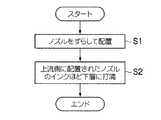
このように、本発明のインクジェット記録方法では、硬化感度の低いインクの順にノズルをずらして配置し(図6のステップS1)、硬化感度の低いインクほど下層に、高いインクほど上層に配置して(記録媒体搬送方向上流側に配置されたノズルのインクほど下層に配置して)画像を形成する(図6のステップS2)ことが好ましい。これにより、表面層の状態を常に一定にすることができ、光沢ムラをより低減することができる。 As described above, in the inkjet recording method of the present invention, the nozzles are shifted in the order of the ink having the lower curing sensitivity (step S1 in FIG. 6), and the ink having the lower curing sensitivity is disposed in the lower layer and the ink having the higher curing sensitivity is disposed in the upper layer. It is preferable to form an image (step S2 in FIG. 6) (the ink of the nozzles arranged upstream in the recording medium conveyance direction is arranged in the lower layer). Thereby, the state of a surface layer can always be made constant and gloss unevenness can be reduced more.
また、UV硬化インクでは、硬化時に記録媒体内部へ浸透せずに表面に立体的な形状を形成するため、打滴するインク量が多量となる4C(シアンインク、マゼンタインク、イエローインク、黒インク)からなる黒ベタ画像において、光沢ムラが顕著となる。その4種のインクからなる濃度の高い画像部分では、淡インクは殆ど用いられない。 In addition, the UV curable ink forms a three-dimensional shape on the surface without penetrating into the inside of the recording medium at the time of curing, and thus 4C (cyan ink, magenta ink, yellow ink, black ink) that requires a large amount of ink to be ejected. ), The uneven glossiness becomes prominent. The light ink is hardly used in the high density image portion composed of the four types of ink.
したがって、図3に示す実施形態では、各色ヘッド112の副走査方向の配置として、濃インクであるYインク、Cインク、Mインクのノズルの間に淡インクのノズルを配置している。このように配置することで、濃インク同士の打滴干渉を低減することができ、光沢ムラを回避することができる。 Therefore, in the embodiment shown in FIG. 3, as the arrangement of the color heads 112 in the sub-scanning direction, the light ink nozzles are arranged between the Y ink, C ink, and M ink nozzles that are dark ink. By disposing in this way, droplet ejection interference between dark inks can be reduced, and uneven gloss can be avoided.
この副走査方向のノズル順序において、各色ヘッド112のノズル114の間隔100dpiの中に各色ノズル114を600dpiで配置することが好ましい。これにより、半硬化用と本硬化用の光源が分離されたインクジェット記録装置において、半硬化光源の照度を低減することで光沢度が高く、かつ光沢ムラの目立たない画像が形成可能となる。
In the nozzle order in the sub-scanning direction, it is preferable that the color nozzles 114 are arranged at 600 dpi in the
このように、各色ヘッド112の副走査方向の位置をインクの硬化感度を鑑みて低感度のインクのノズルほど記録媒体搬送方向の上流方向にずらし、かつ濃インクのノズル間に淡インクのノズルを入れることで、高濃度の画像を形成時に濃インクのドット間が開くので、半硬化用光源の光量をより低減でき、光沢を増すことと光沢ムラの回避を同時に実現することが可能となる。 In this way, the position of each color head 112 in the sub-scanning direction is shifted in the upstream direction of the recording medium conveyance direction in consideration of the ink curing sensitivity, and the light ink nozzles are arranged between the dark ink nozzles. By inserting the gap, the space between the dark ink dots is opened when forming a high-density image, so that the amount of light from the semi-curing light source can be further reduced, and it is possible to simultaneously increase gloss and avoid uneven gloss.
なお、本実施形態では、淡インクとしてLCインクとLMインクの2色のインクを用いているが、淡インクは2色に限定されない。Kインクと同色系であってKインクよりも着色剤濃度が低いライトブラックインク(LKインク)や、Yインクと同色系であってYインクよりも着色剤濃度が低いライトイエローインク(LYインク)を用いて、1色〜4色の構成とすることも可能である。この場合も、各色ヘッド112の副走査方向の配置として、濃インクであるKインク、Yインク、Cインク、Mインクのノズルの間に淡インクのノズルを配置することで、濃インク同士の打滴干渉を低減することができる。 In this embodiment, two colors of ink, LC ink and LM ink, are used as the light ink, but the light ink is not limited to two colors. Light black ink (LK ink) that is the same color as K ink and has a lower colorant concentration than K ink, or light yellow ink (LY ink) that is the same color as Y ink and has a lower colorant concentration than Y ink It is also possible to adopt a configuration of one to four colors using Also in this case, as the arrangement of the color heads 112 in the sub-scanning direction, the light ink nozzles are arranged between the K ink, Y ink, C ink, and M ink nozzles, which are dark inks. Drop interference can be reduced.
なお、本実施形態では、各色ヘッド112の副走査方向の位置を低感度のインクのノズルほど記録媒体搬送方向の上流方向にずらしたが、最も硬化感度の低いインクのノズルを最上流側に配置し、この最も硬化感度の低いインクを記録媒体に最も近い層に配置すれば、その他のインクの配置順が異なっていても光沢ムラの回避に対して一定の効果がある。 In this embodiment, the position of each color head 112 in the sub-scanning direction is shifted to the upstream side in the recording medium conveyance direction as the nozzle of the low sensitivity ink. However, the ink nozzle having the lowest curing sensitivity is arranged on the most upstream side. If the ink having the lowest curing sensitivity is arranged in the layer closest to the recording medium, there is a certain effect for avoiding uneven glossiness even if the arrangement order of the other inks is different.
例えば、前記6色のインクを用いる場合、記録媒体120の搬送方向の最上流側に硬化感度の最も低いインクのノズル114Kを配置し、Kインクが最初に記録媒体120の表面に着弾(すなわち、記録媒体120の記録面に最も近い層に着弾)すればよい。その他のノズルについては、下流側に向かって114K、114C、114LM、114M、114LC、114Yの順や、114K、114M、114LC、114Y、114LM、114Cの順等でもよい。
For example, when the six color inks are used, the
また、本発明のインクジェット記録方法に好適に用いることができる他のインクジェット記録装置について図を参照して説明するが、本実施形態はこれらに限定されないことはいうまでもない。
図7は、本発明のインクジェット記録方法に好適に用いることができる他のインクジェット記録装置の外観斜視図である。このインクジェット記録装置10は、紫外線硬化型インク(UV硬化インク)を用いて記録媒体12上にカラー画像を形成するワイドフォーマットプリンタである。ワイドフォーマットプリンタとは、大型ポスターや商業用壁面広告など、広い描画範囲を記録するのに好適な装置である。ここでは、A3ノビ以上に対応するものを「ワイドフォーマット」と呼ぶ。
Further, other ink jet recording apparatuses that can be suitably used in the ink jet recording method of the present invention will be described with reference to the drawings, but it goes without saying that the present embodiment is not limited to these.
FIG. 7 is an external perspective view of another ink jet recording apparatus that can be suitably used in the ink jet recording method of the present invention. The ink
インクジェット記録装置10は、装置本体20と、この装置本体20を支持する支持脚22とを備えている。装置本体20には、記録媒体(メディア)12に向けてインクを吐出するドロップオンデマンド型のインクジェットヘッド24と、記録媒体12を支持するプラテン26と、ヘッド移動手段としてのガイド機構28及びキャリッジ30(走査手段の一例)が設けられている。
The ink
ガイド機構28は、プラテン26の上方において、記録媒体12の搬送方向(X方向、第1の方向)に直交し、かつプラテン26の媒体支持面と平行な走査方向(Y方向、第2の方向)に沿って延在するように配置されている。キャリッジ30は、ガイド機構28に沿ってY方向に往復移動可能に支持されている。キャリッジ30には、インクジェットヘッド24が搭載されるとともに、記録媒体12上のインクに紫外線を照射する仮硬化光源32A、32Bと、本硬化光源34A、34Bとが搭載されている。
The
仮硬化光源32A、32Bは、インクジェットヘッド24から吐出されたインク滴が記録媒体12に着弾した後に、隣接液滴同士が合一化しない程度にインクを仮硬化(半硬化)させるための紫外線を照射する光源である。本硬化光源34A、34Bは、仮硬化後に追加露光を行い、最終的にインクを完全に硬化(本硬化)させるための紫外線を照射する光源である。
The temporary
キャリッジ30上に配置されたインクジェットヘッド24、仮硬化光源32A、32B及び本硬化光源34A、34Bは、ガイド機構28に沿ってキャリッジ30と共に一体的に(一緒に)移動する。
The
記録媒体12は、後述にても説明するが、紙、不織布、塩化ビニル、合成化学繊維、ポリエチレン樹脂、ポリエステル樹脂、ターポリンなど、材質を問わず、また、浸透性媒体、非浸透性媒体を問わず、様々な媒体を用いることができる。記録媒体12は、装置の背面側からロール紙状態(図8参照)で給紙され、印字後は装置正面側の巻き取りローラ(図7中不図示、図8の符号44)で巻き取られる(移動手段の一例)。プラテン26上に搬送された記録媒体12に対して、インクジェットヘッド24からインク滴が吐出され、記録媒体12上に付着したインク滴に対して仮硬化光源32A、32B、本硬化光源34A、34Bから紫外線が照射される。
As will be described later, the
図7において、装置本体20の正面に向かって左側の前面に、インクカートリッジ36の取り付け部38が設けられている。インクカートリッジ36は、紫外線硬化型インクを貯留する交換自在なインク供給源(インクタンク)である。インクカートリッジ36は、本例のインクジェット記録装置10で使用される各色インクに対応して設けられている。色別の各インクカートリッジ36は、それぞれ独立に形成された不図示のインク供給経路によってインクジェットヘッド24に接続される。各色のインク残量が少なくなった場合にインクカートリッジ36の交換が行われる。
In FIG. 7, a mounting
また、図示を省略するが、装置本体20の正面に向かって右側には、インクジェットヘッド24のメンテナンス部が設けられている。該メンテナンス部には、非印字時におけるインクジェットヘッド24を保湿するためのキャップと、インクジェットヘッド24のノズル面(インク吐出面)を清掃するための払拭部材(ブレード、ウエブ等)が設けられている。インクジェットヘッド24のノズル面をキャッピングするキャップには、メンテナンスのためにノズルから吐出されたインク滴を受けるためのインク受けが設けられている。
Although not shown, a maintenance unit for the
〔記録媒体搬送路の説明〕
図8は、インクジェット記録装置10における記録媒体搬送路を模式的に示す説明図である。図8に示すように、プラテン26は逆樋状に形成され、その上面が記録媒体12の支持面(「媒体支持面」という。)となる。プラテン26の近傍における記録媒体搬送方向(X方向)の上流側には、記録媒体12を間欠搬送するための記録媒体搬送手段である一対のニップローラ40が配設される。このニップローラ40は記録媒体12をプラテン26上でX方向へ移動させる。
[Description of recording medium transport path]
FIG. 8 is an explanatory diagram schematically showing a recording medium conveyance path in the
ロール・ツー・ロール方式の媒体搬送手段を構成する供給側のロール(「送り出し供給ロール」という。)42から送り出された記録媒体12は、印字部の入り口(プラテン26の記録媒体搬送方向の上流側)に設けられた一対のニップローラ40によって、X方向に間欠搬送される。インクジェットヘッド24の直下の印字部に到達した記録媒体12は、インクジェットヘッド24により印字が実行され、印字後に巻き取りローラ44に巻き取られる。印字部の記録媒体搬送方向の下流側には、記録媒体12のガイド46が設けられている。
The
印字部においてインクジェットヘッド24と対向する位置にあるプラテン26の裏面(記録媒体12を支持する面と反対側の面)には、印字中の記録媒体12の温度を調整するための温調部50が設けられている。印字時の記録媒体12が所定の温度となるように調整されると、記録媒体12に着弾したインク液滴の粘度や、表面張力等の物性値が所望の値になり、所望のドット径を得ることが可能となる。なお、必要に応じて、温調部50の上流側にプレ温調部52を設けてもよいし、温調部50の下流側にアフター温調部54を設けてもよい。
A
〔インクジェットヘッドの説明〕
図9は、キャリッジ30上に配置されるインクジェットヘッド24と仮硬化光源32A、32B及び本硬化光源34A、34Bの配置形態の例を示す平面透視図である。
[Description of inkjet head]
FIG. 9 is a plan perspective view showing an example of the arrangement of the
インクジェットヘッド24には、CL(クリア)、W(ホワイト)、LM、K、C、M、Y、LCの各色のインク毎に、それぞれインクを吐出するためのノズル列61CL、61W、61LM、61K、61C、61M、61Y、61LC、61CL、61Wが設けられている。図9では、ノズル列を点線により図示し、簡略化して記載しており、各ノズル列のずれ及びノズルの個別の図示は省略されている。また、以下の説明では、ノズル列61CL、61W、61LM、61K、61C、61M、61Y、61LC、61CL、61Wを総称して、符号61を付してノズル列を表すことがある。
The
インク色の種類(色数)や色の組合せについては、図9に示す態様に限定されない。例えば、LC、LMのノズル列を省略する形態、CLやWのノズル列を省略する形態、特別色のインクを吐出するノズル列を追加する形態などが可能である。また、色別のノズル列のY方向の配置順序も特に限定はない。 The types of ink colors (number of colors) and color combinations are not limited to those shown in FIG. For example, a form in which the LC and LM nozzle arrays are omitted, a form in which the CL and W nozzle arrays are omitted, and a form in which a nozzle array for ejecting special color ink is added are possible. Further, there is no particular limitation on the arrangement order of the nozzle rows for each color in the Y direction.
色別のノズル列61毎にヘッドモジュールを構成し、これらを並べることによって、カラー描画が可能なインクジェットヘッド24を構成することができる。例えば、ノズル列61CL、61W、61LM、61K、61C、61M、61Y、61LCをそれぞれ有する各ヘッドモジュール24CL、24W、24LM、24K、24C、24M、24Y、24LCを、キャリッジ30のY方向に並ぶように等間隔に配置する態様も可能である。
By forming a head module for each color nozzle row 61 and arranging them, it is possible to form an
色別のヘッドモジュール24CL、24W、24LM、24K、24C、24M、24Y、24LCを、それぞれ「インクジェットヘッド」と解釈することも可能である。あるいはまた、1つのインクジェットヘッド24の内部で色別にインク流路を分けて形成し、1ヘッドで複数色のインクを吐出するノズル列を備える構成も可能である。
Each of the color-specific head modules 24CL, 24W, 24LM, 24K, 24C, 24M, 24Y, and 24LC may be interpreted as an “inkjet head”. Alternatively, a configuration in which an ink flow path is formed separately for each color inside one
各ノズル列61は、複数個のノズルが一定の間隔でX方向に沿って1列に(直線的に)並んだものとなっている。本例のインクジェットヘッド24は、各ノズル列61を構成するノズルの配置ピッチ(ノズルピッチ)が254μm(100dpi)、1列のノズル列61を構成するノズルの数は256ノズル、ノズル列61の全長Lw(「ノズル列の長さ」に相当、「ノズル列幅」という場合がある。)は約65mm(254μm×255=64.8mm)である。
Each nozzle row 61 has a plurality of nozzles arranged in a line (linearly) along the X direction at regular intervals. In the
また、ノズル列61LM、61K、61C、61M、61Y、61LCは、各ノズルがX方向にそれぞれずらして配置されており(不図示)、メディア搬送方向上流側から最も硬化感度の低いKインクを吐出するノズル列61K、2番目に硬化感度の低いYインクを吐出するノズル列61Y、の順に並んでいる。また、濃インクであるYインク、Cインク、Mインクのノズルの間に淡インクであるLMインク、LCインクのノズルが配置されている(図5参照)。なお、硬化感度の低い濃インクほどメディア搬送方向上流側に配置してもよい。 The nozzle arrays 61LM, 61K, 61C, 61M, 61Y, and 61LC are arranged such that each nozzle is shifted in the X direction (not shown), and the K ink having the lowest curing sensitivity is ejected from the upstream side in the media conveyance direction. Are arranged in the order of the nozzle row 61 </ b> K that performs, and the nozzle row 61 </ b> Y that discharges Y ink having the second lowest curing sensitivity. Further, LM ink and LC ink nozzles which are light inks are arranged between nozzles of Y ink, C ink and M ink which are dark inks (see FIG. 5). Note that dark ink with lower curing sensitivity may be arranged on the upstream side in the media conveyance direction.
また、吐出周波数は15kHzであり、駆動波形の変更によって10pl、20pl、30plの3種類の吐出液滴量を打ち分けることができる。すなわち、小ドット、中ドット、大ドットの3種類の大きさのドットを形成することができる。 Further, the discharge frequency is 15 kHz, and three types of discharge droplet amounts of 10 pl, 20 pl, and 30 pl can be distinguished by changing the drive waveform. That is, it is possible to form three sizes of dots, small dots, medium dots, and large dots.
インクジェットヘッド24のインク吐出方式としては、圧電素子(ピエゾアクチュエータ)の変形によってインク滴を飛ばす方式(ピエゾジェット方式)が採用されている。吐出エネルギー発生素子として、静電アクチュエータを用いる形態(静電アクチュエータ方式)の他、ヒータなどの発熱体(加熱素子)を用いてインクを加熱して気泡を発生させ、その圧力でインク滴を飛ばす形態(サーマルジェット方式)を採用することも可能である。
As an ink ejection method of the
〔紫外線照射装置の配置について〕
図9に示したように、インクジェットヘッド24の走査方向(Y方向)の左右両脇に、仮硬化光源32A、32Bが配置される。更に、インクジェットヘッド24の記録媒体搬送方向(X方向)の下流側に本硬化光源34A、34Bが配置されている。
インクジェットヘッド24のノズルから吐出されて記録媒体12上に着弾したインク滴には、その直後にその上を通過する仮硬化光源32A(又は32B)によって仮硬化のための紫外線が照射される。また、記録媒体12の間欠搬送に伴ってインクジェットヘッド24の印字領域を通過した記録媒体12上のインク滴には、本硬化光源34A、34Bにより本硬化のための紫外線が照射される。
なお、仮硬化光源32A、32B、本硬化光源34A、34Bは、インクジェット記録装置10の印刷動作中は常時点灯していてもよいし、必要に応じて適宜点灯と消灯を制御してもよい。
[About the layout of ultraviolet irradiation equipment]
As shown in FIG. 9, provisional curing light sources 32 </ b> A and 32 </ b> B are arranged on the left and right sides of the scanning direction (Y direction) of the
The ink droplets ejected from the nozzles of the
The temporary
〔仮硬化光源の構成例について〕
図9に示したように、仮硬化光源32A、32Bは、それぞれ複数個のUV−LED素子33が並べられた構造を有している。2つの仮硬化光源32A、32Bは、共通の構成である。本例では、仮硬化光源32A、32Bとして、X方向に沿って6個のUV−LED素子33が1列に並べたLED素子配列を例示したが、LED素子数及びその配列形態はこの例に限定されない。例えば、複数個のLED素子をX/Y方向にマトリクス状に配置した構成も可能である。
この6個のUV−LED素子33は、インクジェットヘッド24のノズル列幅Lwと同じ幅の領域に対して一度にUV照射を行うことができるように並べられている。
[Configuration example of temporary curing light source]
As shown in FIG. 9, each of the temporary
The six UV-
〔本硬化光源の構成例について〕
図9に示したように、本硬化光源34A、34Bは、それぞれ複数個のUV−LED素子35が並べられた構造を有している。2つの本硬化光源34A、34Bは、共通の構成である。図9の例では、本硬化光源34A、34Bとして、Y方向に6個、X方向に2個のUV−LED素子35がマトリクス状に配置されたLED素子配列(6×2)を例示している。
[Configuration example of the main curing light source]
As shown in FIG. 9, each of the main
UV−LED素子35のX方向の配置は、後述するスワス幅と関連し、キャリッジ30の一度の走査において、ノズル列幅Lwのn分の1(nは正の整数)に対応する幅の領域に対して一度にUV照射を行うことができるように決められる。図9の例では、ノズル列幅Lwの1/2(n=2)の幅の領域を一度に照射可能にUV−LED素子35が配置されている。
The arrangement of the UV-
なお、本硬化光源のLED素子数及びその配列形態は、図9の例に限定されない。また、仮硬化光源32A、32B、本硬化光源34A、34Bの発光源としては、UV−LED素子33、35に限らず、UVランプなどを用いることも可能である。
In addition, the number of LED elements of the main curing light source and the arrangement form thereof are not limited to the example of FIG. Further, the light sources of the temporary
〔作画モードについて〕
上記のごとく構成されたインクジェット記録装置10は、マルチパス方式の描画制御が適用され、印字パス数の変更によって印字解像度を変更することが可能である。例えば、高生産モード、標準モード、高画質モードの3種類の作画モードが用意され、各モードでそれぞれ印字解像度が異なる。印刷目的や用途に応じて作画モードを選択することができる。
[About drawing mode]
The
高生産モードでは、600dpi(主走査方向)×400dpiまたは500dpi(副走査方向)の解像度で印字が実行される。高生産モードの場合、主走査方向は2パス(2回の走査)によって600dpiの解像度が実現される。まず、1回目の走査(キャリッジ30の往路)では300dpiの解像度でドットが形成される。2回目の走査(復路)では、1回目の走査(往路)で形成されたドットの中間を300dpiで補間するようにドットが形成され、主走査方向について600dpiの解像度が得られる。
一方、副走査方向については、ノズルピッチが100dpiであり、1回の主走査(1パス)により副走査方向に100dpiの解像度でドットが形成される。したがって、4パス印字(4回の走査又は5回の走査)により補間印字を行うことで400dpi又は500dpiの解像度が実現される。
なお、本明細書では、主走査方向のパス数と副走査方向のパス数との積を、その作画モードにおけるパス数と呼ぶ。したがって、高生産モードのパス数は、主走査2パス印字×副走査4パス印字または5パス印字=8パスまたは10パス印字となる。
In the high production mode, printing is executed with a resolution of 600 dpi (main scanning direction) × 400 dpi or 500 dpi (sub-scanning direction). In the high production mode, a resolution of 600 dpi is realized by two passes (two scans) in the main scanning direction. First, dots are formed with a resolution of 300 dpi in the first scan (the forward path of the carriage 30). In the second scan (return pass), dots are formed such that the middle of the dots formed in the first scan (forward pass) is interpolated at 300 dpi, and a resolution of 600 dpi is obtained in the main scan direction.
On the other hand, in the sub-scanning direction, the nozzle pitch is 100 dpi, and dots are formed at a resolution of 100 dpi in the sub-scanning direction by one main scanning (one pass). Therefore, a resolution of 400 dpi or 500 dpi is realized by performing interpolation printing by four-pass printing (four scans or five scans).
In this specification, the product of the number of passes in the main scanning direction and the number of passes in the sub-scanning direction is referred to as the number of passes in the drawing mode. Therefore, the number of passes in the high production mode is main scanning 2-pass printing × sub-scanning 4-pass printing or 5-pass printing = 8-pass or 10-pass printing.
標準モードでは、900dpi×800dpiの解像度で印字が実行される。この解像度は、主走査方向は2パス印字、副走査方向は8パス印字とすることにより得られる。すなわち、標準モードのパス数は、主走査2パス印字×副走査8パス印字=16パスとなる。
また、高画質モードでは、1,200×1,200dpiの解像度で印字が実行され、主走査方向は4パス、副走査方向は12パスによりこの解像度を得ている。すなわち、高画質モードのパス数は、主走査4パス印字×副走査12パス印字=48パスとなる。
In the standard mode, printing is performed with a resolution of 900 dpi × 800 dpi. This resolution can be obtained by 2-pass printing in the main scanning direction and 8-pass printing in the sub-scanning direction. That is, the number of passes in the standard mode is main scanning 2-pass printing × sub-scanning 8-pass printing = 16 passes.
In the high image quality mode, printing is performed with a resolution of 1,200 × 1,200 dpi, and this resolution is obtained with four passes in the main scanning direction and 12 passes in the sub-scanning direction. That is, the number of passes in the high image quality mode is main scanning 4 pass printing ×
〔インク供給系の説明〕
図10は、インクジェット記録装置10のインク供給系の構成を示すブロック図である。同図に示すように、インクカートリッジ36に収容されているインクは、供給ポンプ70によって吸引され、サブタンク72を介してインクジェットヘッド24に送られる。サブタンク72には、内部のインクの圧力を調整するための圧力調整部74が設けられている。
圧力調整部74は、バルブ76を介してサブタンク72と連通される加減圧用ポンプ77と、バルブ76と加減圧用ポンプ77との間に設けられる圧力計78と、を具備している。
通常の印字時は、加減圧用ポンプ77がサブタンク72内のインクを吸引する方向に動作し、サブタンク72の内部圧力及びインクジェットヘッド24の内部圧力が負圧に維持される。一方、インクジェットヘッド24のメンテナンス時は、加減圧用ポンプ77がサブタンク72内のインクを加圧する方向に動作し、サブタンク72の内部及びインクジェットヘッド24の内部が強制的に加圧され、インクジェットヘッド24内のインクがノズルを介して排出される。インクジェットヘッド24から強制的に排出されたインクは、上述したキャップ(図示せず)のインク受けに収容される。
[Description of ink supply system]
FIG. 10 is a block diagram showing the configuration of the ink supply system of the
The
During normal printing, the pressure increasing / decreasing
〔インクジェット記録装置の制御系の説明〕
図11はインクジェット記録装置10の構成を示すブロック図である。同図に示すように、インクジェット記録装置10は、制御手段としての制御装置202が設けられている。制御装置202としては、例えば、中央演算処理装置(CPU)を備えたコンピュータ等を用いることができる。制御装置202は、図4に示した制御部138に該当し、所定のプログラムに従ってインクジェット記録装置10の全体を制御する制御装置として機能するとともに、各種演算を行う演算装置として機能する。制御装置202には、記録媒体搬送制御部204、キャリッジ駆動制御部206、光源制御部208、画像処理部210、吐出制御部212が含まれる。これらの各部は、ハードウェア回路又はソフトウェア、若しくはこれらの組合せによって実現される。
記録媒体搬送制御部204は、記録媒体12(図7参照)の搬送を行うための搬送駆動部214を制御する。搬送駆動部214は、図4に示した記録媒体搬送機構132に該当し、図8に示すニップローラ40を駆動する駆動用モータ、及びその駆動回路が含まれる。プラテン26(図7参照)上に搬送された記録媒体12は、インクジェットヘッド24による主走査方向の往復走査(印刷パスの動き)に合わせて、スワス幅単位で副走査方向へ間欠送りされる。
[Description of control system of inkjet recording apparatus]
FIG. 11 is a block diagram showing the configuration of the
The recording medium
図11に示すキャリッジ駆動制御部206は、キャリッジ30(図7参照)を主走査方向に移動させるための主走査駆動部216を制御する。主走査駆動部216は、図4に示したキャリッジ走査機構130に該当し、キャリッジ30の移動機構に連結される駆動用モータ、及びその制御回路が含まれる。
光源制御部208は、LED駆動回路218を介して仮硬化光源32A、32BのUV−LED素子33の発光量を調整するとともに、LED駆動回路219を介して本硬化光源34A、34BのUV−LED素子35の発光量を調整する制御手段である。
LED駆動回路218は、光源制御部208からの指令に応じた電圧値の電圧を出力して、UV−LED素子33の発光量を調整する。また、LED駆動回路219は、光源制御部208からの指令に応じた電圧値の電圧を出力して、UV−LED素子35の発光量を調整する。LEDの発光量の調整は、電圧を変更するのではなく、PWM(Pulse Width Modulation)を用いて駆動波形のDuty比を変更することによって行ってもよいし、電圧値とDuty比の両方を変更してもよい。
A carriage
The light
The
制御装置202には、操作パネル等の入力装置220、表示装置222が接続されている。
入力装置220は、手動による外部操作信号を制御装置202へ入力する手段であり、例えば、キーボード、マウス、タッチパネル、操作ボタンなど各種形態を採用し得る。表示装置222には、液晶ディスプレイ、有機ELディスプレイ、CRTなど、各種形態を採用し得る。オペレータは、入力装置220を操作することにより、作画モードの選択、印刷条件の入力や付属情報の入力・編集などを行うことができ、入力内容や検索結果等の各種情報は、表示装置222の表示を通じて確認することができる。
An
The
また、インクジェット記録装置10には、各種情報を格納しておく情報記憶部224と、印刷用の画像データを取り込むための画像入力インターフェース226が設けられている。画像入力インターフェースには、シリアルインターフェースを適用してもよいし、パラレルインターフェースを適用してもよい。この部分には、通信を高速化するためのバッファメモリ(不図示)を搭載してもよい。
画像入力インターフェース226を介して入力された画像データは、画像処理部210にて印刷用のデータ(ドットデータ)に変換される。このドットデータは、一般に、多階調の画像データに対して色変換処理、ハーフトーン処理を行って生成される。
Further, the ink
Image data input via the
ハーフトーン処理の手段としては、誤差拡散法、ディザ法、閾値マトリクス法、濃度パターン法など、各種公知の手段を適用できる。ハーフトーン処理は、一般にM値(M≧3)の階調画像データをN値(N<M)の階調画像データに変換する。最も簡単な例では、2値(ドットのオンオフ)のドット画像データに変換するが、ハーフトーン処理において、ドットサイズの種類(例えば、大ドット、中ドット、小ドットなどの3種類)に対応した多値の量子化を行うことも可能である。
こうして得られた2値又は多値の画像データ(ドットデータ)は、各ノズルの駆動(オン)/非駆動(オフ)、更に、多値の場合には液滴量(ドットサイズ)を制御するインク吐出データ(打滴制御データ)として利用される。
Various known means such as an error diffusion method, a dither method, a threshold matrix method, and a density pattern method can be applied as the halftone processing means. The halftone process generally converts gradation image data having an M value (M ≧ 3) into gradation image data having an N value (N <M). In the simplest example, it is converted into binary (dot on / off) dot image data, but in halftone processing, it corresponds to the dot size type (for example, three types such as large dot, medium dot, small dot). It is also possible to perform multi-level quantization.
The binary or multi-valued image data (dot data) obtained in this way controls the driving (ON) / non-driving (OFF) of each nozzle, and in the case of multiple values, controls the droplet amount (dot size). Used as ink ejection data (droplet ejection control data).
吐出制御部212は、画像処理部210において生成されたドットデータに基づいて、ヘッド駆動回路228に対して吐出制御信号を生成する。また、吐出制御部212は、不図示の駆動波形生成部を備えている。駆動波形生成部は、インクジェットヘッド24の各ノズルに対応した吐出エネルギー発生素子(本例では、ピエゾ素子)を駆動するための駆動電圧信号を生成する手段である。
駆動電圧信号の波形データは、予め情報記憶部224に格納されており、必要に応じて使用する波形データが出力される。駆動波形生成部から出力された信号(駆動波形)は、ヘッド駆動回路228に供給される。なお、駆動波形生成部から出力される信号はデジタル波形データであってもよいし、アナログ電圧信号であってもよい。
ヘッド駆動回路228を介してインクジェットヘッド24の各吐出エネルギー発生素子に対して、共通の駆動電圧信号が印加され、各ノズルの吐出タイミングに応じて各エネルギー発生素子の個別電極に接続されたスイッチ素子(不図示)のオンオフを切り換えることで、対応するノズルからインクが吐出される。
The
The waveform data of the drive voltage signal is stored in advance in the information storage unit 224, and waveform data to be used is output as necessary. The signal (drive waveform) output from the drive waveform generation unit is supplied to the
A common driving voltage signal is applied to each ejection energy generating element of the
情報記憶部224には、制御装置202のCPUが実行するプログラム、及び制御に必要な各種データなどが格納されている。情報記憶部224には、作画モードに応じた解像度の設定情報、パス数(スキャンの繰り返し数)、仮硬化光源32A、32B及び本硬化光源34A、34Bの発光量情報などが格納されている。
The information storage unit 224 stores programs executed by the CPU of the
エンコーダ230は、主走査駆動部216の駆動用モータ、及び搬送駆動部214の駆動用モータに取り付けられており、該駆動モータの回転量及び回転速度に応じたパルス信号を出力し、該パルス信号は制御装置202に送られる。エンコーダ230から出力されたパルス信号に基づいて、キャリッジ30の位置、及び、記録媒体12(図7参照)の位置が把握される。
The
センサ232は、キャリッジ30に取り付けられており、センサ232から得られたセンサ信号に基づいて記録媒体12の幅が把握される。
The sensor 232 is attached to the
以上のように構成されたインクジェット記録装置10によれば、各色インクのヘッドをノズルピッチ内でそれぞれ記録媒体搬送方向にずらし、低感度のインクのヘッドほど記録媒体搬送方向上流側に配置し、低感度のインクほど下層に配置して記録することで、表面層の状態を常に一定にして光沢ムラを低減することができる。
According to the
上記の実施形態では、UV硬化インクを用いて画像を形成する例を用いて説明しているが、活性エネルギーの付与により硬化する硬化性インクを用いた場合に適用することができる。例えば、X線、分子線、又はイオンビーム等により硬化するインクを用いることができる。 In the above-described embodiment, an example in which an image is formed using UV curable ink is described. However, the present invention can be applied to a case where curable ink that is cured by applying active energy is used. For example, an ink that is cured by X-ray, molecular beam, ion beam, or the like can be used.
<吐出工程>
本発明のインクジェット記録方法は、記録媒体上に、前記インクジェット記録装置のインクジェットヘッドから少なくとも1種の前記インクを吐出する吐出工程を含む。
前記吐出工程は、前記インクジェット記録装置のインクジェットヘッドから少なくとも2種の前記インクを吐出する工程であることが好ましく、前記インクジェット記録装置のインクジェットヘッドから少なくともシアン、マゼンタ、イエロー及びブラックの4色の前記インクを吐出する工程であることがより好ましい。上記態様であると、本発明の効果をより発揮できる。
また、前記吐出工程におけるインクジェットヘッドのスキャンスピードは、0.5m/s以上であることが好ましく、0.7m/s以上であることがより好ましく、0.9m/s以上であることが更に好ましい。また、3.5m/s以下であることが好ましく、3.0m/s以下であることがより好ましく、2.5m/s以下であることが更に好ましい。上記態様であると、画像における光沢ムラがより生じやすい態様であり、本発明の効果をより発揮することができる。
<Discharge process>
The inkjet recording method of the present invention includes an ejection step of ejecting at least one kind of the ink from an inkjet head of the inkjet recording apparatus onto a recording medium.
The ejection step is preferably a step of ejecting at least two types of the ink from the inkjet head of the inkjet recording apparatus, and the at least four colors of cyan, magenta, yellow and black are ejected from the inkjet head of the inkjet recording apparatus. More preferably, it is a step of discharging ink. The effect of this invention can be exhibited more as it is the said aspect.
Further, the scanning speed of the inkjet head in the ejection step is preferably 0.5 m / s or more, more preferably 0.7 m / s or more, and further preferably 0.9 m / s or more. . Moreover, it is preferable that it is 3.5 m / s or less, It is more preferable that it is 3.0 m / s or less, It is still more preferable that it is 2.5 m / s or less. In the above aspect, gloss unevenness in an image is more likely to occur, and the effects of the present invention can be further exhibited.
本発明において、記録媒体としては、特に限定されず、公知の記録媒体を使用することができる。例えば、紙、プラスチック(例えば、ポリエチレン、ポリプロピレン、ポリスチレン等)がラミネートされた紙、金属板(例えば、アルミニウム、亜鉛、銅等)、プラスチックフィルム(例えば、二酢酸セルロース、三酢酸セルロース、プロピオン酸セルロース、酪酸セルロース、酢酸酪酸セルロース、硝酸セルロース、ポリエチレンテレフタレート、ポリエチレン、ポリスチレン、ポリプロピレン、ポリカーボネート、ポリビニルアセタール等)、上述した金属がラミネートされ又は蒸着された紙又はプラスチックフィルム等が挙げられる。 In the present invention, the recording medium is not particularly limited, and a known recording medium can be used. For example, paper, paper laminated with plastic (eg, polyethylene, polypropylene, polystyrene, etc.), metal plate (eg, aluminum, zinc, copper, etc.), plastic film (eg, cellulose diacetate, cellulose triacetate, cellulose propionate) Cellulose butyrate, cellulose acetate butyrate, cellulose nitrate, polyethylene terephthalate, polyethylene, polystyrene, polypropylene, polycarbonate, polyvinyl acetal, etc.), paper or plastic film on which the above-mentioned metal is laminated or deposited.
前記吐出工程におけるインクの吐出は、インクを、好ましくは25〜80℃、より好ましくは25〜50℃に加熱して、インクの粘度を、好ましくは3〜15mPa・s、より好ましくは3〜13mPa・sに下げた後に行うことが好ましい。特に、本発明のような25℃におけるインクの粘度が10〜30mPa・sであるものを用いると、良好に吐出が行えるので好ましい。この方法を用いることにより、高い吐出安定性を実現することができる。
放射線硬化型インクは、概して通常インクジェット記録用インクで使用される水性インク組成物より粘度が高いため、吐出時の温度変動による粘度変動が大きい。インクの粘度変動は、液滴サイズの変化及び液滴吐出速度の変化に対して大きな影響を与え、ひいては画質劣化を引き起こす。したがって、吐出時のインクの温度はできるだけ一定に保つことが必要である。よって、インクの温度の制御幅は、設定温度の±5℃であることが好ましく、設定温度の±2℃であることがより好ましく、設定温度±1℃であることが更に好ましい。
In the ejection step, the ink is preferably heated to 25 to 80 ° C., more preferably 25 to 50 ° C., and the viscosity of the ink is preferably 3 to 15 mPa · s, more preferably 3 to 13 mPa. -It is preferable to perform after lowering to s. In particular, it is preferable to use an ink having a viscosity of 10 to 30 mPa · s at 25 ° C. as in the present invention because it can be discharged well. By using this method, high ejection stability can be realized.
Since the radiation curable ink generally has a higher viscosity than the water-based ink composition usually used in ink jet recording ink, the viscosity fluctuation due to temperature fluctuation during ejection is large. The ink viscosity fluctuation has a great influence on the change of the droplet size and the change of the droplet discharge speed, and causes the image quality deterioration. Therefore, it is necessary to keep the temperature of the ink at the time of ejection as constant as possible. Therefore, the control range of the temperature of the ink is preferably ± 5 ° C. of the set temperature, more preferably ± 2 ° C. of the set temperature, and further preferably ± 1 ° C. of the set temperature.
<硬化工程>
本発明のインクジェット記録方法は、前記活性エネルギー付与手段から活性エネルギーを照射して、吐出された前記インクを硬化する硬化工程を含む。
記録媒体上に吐出されたインクは、活性エネルギーを照射することによって硬化する。
前記活性エネルギー付与手段による記録媒体表面における最高照度は、画質及び生産性の観点から、10〜3,000mW/cm2であることが好ましく、50〜2,100mW/cm2がより好ましく、100〜1,600mW/cm2が更に好ましい。
前記活性エネルギー付与手段の前記発光ダイオードにより付与するエネルギー、すなわち紫外線の照射により記録媒体上のインクに付与するエネルギー(積算光量)は、100〜1,000mJ/cm2が好ましく、150〜800mJ/cm2がより好ましく、200〜700mJ/cm2が更に好ましい。上記範囲であると、生産性と硬化性を両立できる。
<Curing process>
The inkjet recording method of the present invention includes a curing step of curing the ejected ink by irradiating active energy from the active energy applying unit.
The ink ejected on the recording medium is cured by irradiating with active energy.
The maximum illuminance on the surface of the recording medium by the active energy applying means is preferably 10 to 3,000 mW / cm 2 , more preferably 50 to 2,100 mW / cm 2 from the viewpoint of image quality and productivity. 1,600 mW / cm 2 is more preferable.
The energy imparted by the light emitting diode of the active energy imparting means, that is, the energy imparted to the ink on the recording medium by ultraviolet irradiation (integrated light amount) is preferably 100 to 1,000 mJ / cm 2 , and preferably 150 to 800 mJ / cm 2. 2 is more preferable, and 200 to 700 mJ / cm 2 is still more preferable. Within the above range, both productivity and curability can be achieved.
本発明のインジェット記録方法においては、活性エネルギーを、好ましくは0.1〜2秒、より好ましくは0.2〜1.5秒、更に好ましくは0.3〜1秒照射することが好ましい。
活性エネルギーの照射は、インクの着弾後、一定時間(好ましくは0.01〜0.5秒、より好ましくは0.01〜0.3秒、更に好ましくは0.01〜0.15秒)をおいて行われることが好ましい。このようにインクの着弾から照射までの時間を極短時間に制御することにより、記録媒体に着弾したインクが硬化前に滲むことを防止することが可能となる。また、多孔質な記録媒体に対しても光源の届かない深部までインクが浸透する前に露光することができるため、未反応モノマーの残留を抑えることができる。
In the inject recording method of the present invention, it is preferable to irradiate the active energy preferably for 0.1 to 2 seconds, more preferably 0.2 to 1.5 seconds, and still more preferably 0.3 to 1 second.
Irradiation with active energy takes a certain period of time (preferably 0.01 to 0.5 seconds, more preferably 0.01 to 0.3 seconds, still more preferably 0.01 to 0.15 seconds) after ink landing. It is preferable to be carried out in In this way, by controlling the time from ink landing to irradiation to an extremely short time, it is possible to prevent the ink that has landed on the recording medium from spreading before curing. Further, since the ink can be exposed to the porous recording medium before the ink penetrates to a deep part where the light source does not reach, the residual unreacted monomer can be suppressed.
前述したように、本発明に用いられるインクジェット記録装置は、前記活性エネルギー付与手段によって活性エネルギーが付与されたインク滴に対して更に活性エネルギーを付与することでインク滴を本硬化させる第2の活性エネルギー付与手段を備えることが好ましい。
また、前記硬化工程が、前記活性エネルギー付与手段から活性エネルギーを照射して、吐出された前記インクを不完全に硬化する(「半硬化」ともいう。)仮硬化工程、及び、前記仮硬化工程において不完全に硬化している前記インクを前記第2の活性エネルギー付与手段から活性エネルギーを照射して完全に硬化する本硬化工程を含むことが好ましい。
なお、本発明における「完全硬化」とは、インクの内部及び表面が完全に硬化した状態をいう。具体的には、普通紙などの浸透媒体を押し当てて、浸透媒体にインクが転写したかどうかによって判断することができる。すなわち、全く転写しない場合を完全に硬化した状態という。
また、本発明における「半硬化」とは、インクが硬化を開始してから完全硬化に至るまでの間の状態をいう。
As described above, the ink jet recording apparatus used in the present invention has the second activity in which the ink droplet is fully cured by further applying the activation energy to the ink droplet to which the activation energy is applied by the activation energy applying means. It is preferable to provide an energy providing means.
In addition, the curing step irradiates active energy from the active energy applying means to incompletely cure the ejected ink (also referred to as “semi-curing”), and the temporary curing step. It is preferable to include a main curing step of completely curing the ink that has been incompletely cured by irradiating active energy from the second active energy applying means.
In the present invention, “completely cured” refers to a state where the inside and the surface of the ink are completely cured. Specifically, the determination can be made based on whether or not the ink is transferred to the permeation medium by pressing the permeation medium such as plain paper. That is, the case where no transfer is performed is called a completely cured state.
In addition, “semi-cured” in the present invention refers to a state between the start of ink curing and the complete curing.
前記仮硬化工程における前記活性エネルギー付与手段の照度は、50〜1,000mW/cm2であることが好ましく、100〜500mW/cm2であることがより好ましい。上記範囲であると、打滴の濡れ広がりが特に促進され、光沢性に優れる印刷物が得られ、また、打滴干渉を起こしにくく、筋ムラの目立たない印刷物が得られる。
また、前記仮硬化工程においては、インクの吐出後0〜1.0秒の間に前記活性エネルギー付与手段により吐出されたインクに活性エネルギーを照射することが好ましく、インクの吐出後0〜0.7秒の間に照射することがより好ましく、インクの吐出後0〜0.5秒の間に照射することが更に好ましく、インクの吐出後0〜0.4秒の間に照射することが特に好ましい。
The illuminance of the active energy application device in temporary curing step is preferably 50~1,000mW / cm 2, more preferably 100~500mW / cm 2. Within the above range, wetting and spreading of the droplets are particularly promoted, and a printed matter having excellent gloss can be obtained, and printed matter which is less prone to droplet interference and has no noticeable stripe unevenness can be obtained.
Further, in the temporary curing step, it is preferable to irradiate the ink ejected by the active energy applying means within 0 to 1.0 seconds after the ink is ejected, and 0 to 0. 0 after the ink is ejected. It is more preferable to irradiate during 7 seconds, it is more preferable to irradiate between 0 to 0.5 seconds after ink discharge, and it is particularly preferable to irradiate between 0 to 0.4 seconds after ink discharge. preferable.
前記本硬化工程において、インクを吐出後から本硬化工程における活性エネルギーの照射までの経過時間の上限については、厳密に規定されることはないが、空気中の埃付着などのコンタミネーションを抑制するなどの観点で、1分以内が好ましく、30秒以内がより好ましく、10秒以内が特に好ましい。また、下限は、前記仮硬化工程の後であれば特に制限はない。
前記第2の活性エネルギー付与手段の照度は、生産性/即乾性と、打滴の濡れ広がりとのバランスの観点から、600〜3,000mW/cm2が好ましく、700〜2,100mW/cm2がより好ましく、800〜1,800mW/cm2が特に好ましい。
In the main curing step, the upper limit of the elapsed time from the ejection of ink to the irradiation of active energy in the main curing step is not strictly defined, but contamination such as dust adhesion in the air is suppressed. In view of the above, it is preferably within 1 minute, more preferably within 30 seconds, and particularly preferably within 10 seconds. The lower limit is not particularly limited as long as it is after the temporary curing step.
The illuminance of the second active energy application means comprises a productivity / quick-drying, in view of the balance between wetting and spreading of the droplet ejection, is preferably 600~3,000mW / cm 2, 700~2,100mW / cm 2 Is more preferable, and 800 to 1,800 mW / cm 2 is particularly preferable.
また、本発明のインクジェット記録方法は、必要に応じ、前記以外の工程を含んでいてもよい。 Moreover, the inkjet recording method of this invention may include processes other than the above as needed.
<インク>
本発明のインクジェット記録方法には、少なくともシアン、マゼンタ、イエロー及びブラックの4色のインクを使用する。
また、本発明のインクジェット記録方法には、前記4色のインクだけでなく、他のインクを使用してもよく、例えば、ライトシアンインク、ライトマゼンタインク等の淡色インク、ホワイトインク、クリアインク、オレンジインク、グリーンインク、バイオレットインク等が挙げられる。
中でも、本発明のインクジェット記録方法は、前記4色のインクに加え、少なくとも1種の淡色インクを使用することが好ましく、前記4色のインクに加え、ライトシアンインク及びライトマゼンタインクを使用することがより好ましい。
なお、ライトシアンインクとは、前記シアンインクよりも着色剤濃度が低いシアンインクであればよく、ライトマゼンタインクとは、前記マゼンタインクよりも着色剤濃度が低いマゼンタインクであればよい。また、淡色インクは、着色剤の含有量がインク組成物全体の2質量%以下のインクであることが好ましい。
また、クリアインクとは、実質的に着色剤を含有せず、透明なインク組成物である。クリアインクは、本発明のインクジェット記録方法において、下塗り層の形成に使用してもよく、また、オーバーコート層(保護層)の形成に使用してもよい。
<Ink>
The ink jet recording method of the present invention uses at least four inks of cyan, magenta, yellow, and black.
In addition, the ink jet recording method of the present invention may use not only the four color inks but also other inks. For example, light inks such as light cyan ink and light magenta ink, white ink, clear ink, orange Examples include ink, green ink, and violet ink.
In particular, in the ink jet recording method of the present invention, it is preferable to use at least one light color ink in addition to the four color inks. In addition to the four color inks, a light cyan ink and a light magenta ink may be used. More preferred.
The light cyan ink may be a cyan ink having a lower colorant concentration than the cyan ink, and the light magenta ink may be a magenta ink having a lower colorant concentration than the magenta ink. Further, the light color ink is preferably an ink having a colorant content of 2% by mass or less of the entire ink composition.
The clear ink is a transparent ink composition that does not substantially contain a colorant. The clear ink may be used for forming an undercoat layer or an overcoat layer (protective layer) in the inkjet recording method of the present invention.
本発明に用いられる前記4色のインクの25℃における粘度は、いずれも10〜30mPa・sであり、10〜25mPa・sであることが好ましい。上記範囲であると、光沢ムラ及び粒状性が低減された画像を得ることができる。
更に、本発明に用いられる全てのインクの25℃における粘度がいずれも、10〜30mPa・sであることが好ましく、10〜25mPa・sであることがより好ましい。上記範囲であると、光沢ムラ及び粒状性がより低減された画像を得ることができる。
なお、粘度は、25℃における粘度であり、東機産業(株)製のVISCOMETER TV−22LTを用いて測定した25℃における粘度であることが好ましい。
The four color inks used in the present invention have a viscosity at 25 ° C. of 10 to 30 mPa · s, preferably 10 to 25 mPa · s. Within the above range, an image with reduced gloss unevenness and graininess can be obtained.
Furthermore, the viscosity at 25 ° C. of all inks used in the present invention is preferably 10 to 30 mPa · s, and more preferably 10 to 25 mPa · s. Within the above range, an image with reduced gloss unevenness and graininess can be obtained.
In addition, a viscosity is a viscosity in 25 degreeC, and it is preferable that it is a viscosity in 25 degreeC measured using Toki Sangyo Co., Ltd. VISCOMETER TV-22LT.
本発明に用いられる前記4色のインクのうち、少なくとも1種のインクの25℃における表面張力は、23〜39mN/mであることが好ましく、30〜39mN/mであることがより好ましい。上記の範囲であると、光沢ムラ及び粒状性がより低減された画像を得ることができる。
また、本発明に用いられる前記4色のインクの25℃における表面張力がいずれも、23〜39mN/mであることが好ましく、30〜39mN/mであることがより好ましい。上記範囲であると、光沢ムラ及び粒状性がより低減された画像を得ることができる。
更に、本発明に用いられる全てのインクの25℃における表面張力がいずれも、23〜39mN/mであることが好ましく、30〜39mN/mであることがより好ましい。上記範囲であると、光沢ムラ及び粒状性がより低減された画像を得ることができる。
なお、本発明におけるインクの表面張力は、一般的に用いられている表面張力計(例えば、協和界面科学(株)製、表面張力計AUTOMATIC SURFACE TENSIOMETER CBVP−Z等)を用いて、ウィルヘルミー法で25℃にて測定した値である。
Of the four color inks used in the present invention, the surface tension at 25 ° C. of at least one kind of ink is preferably 23 to 39 mN / m, and more preferably 30 to 39 mN / m. Within the above range, an image with reduced gloss unevenness and graininess can be obtained.
Further, the surface tension at 25 ° C. of the four color inks used in the present invention is preferably 23 to 39 mN / m, and more preferably 30 to 39 mN / m. Within the above range, an image with reduced gloss unevenness and graininess can be obtained.
Furthermore, the surface tension at 25 ° C. of all inks used in the present invention is preferably 23 to 39 mN / m, and more preferably 30 to 39 mN / m. Within the above range, an image with reduced gloss unevenness and graininess can be obtained.
The surface tension of the ink in the present invention is determined by the Wilhelmy method using a commonly used surface tension meter (for example, surface tension meter AUTOMATIC SURFACE TENSIOMETER CBVP-Z manufactured by Kyowa Interface Science Co., Ltd.). It is the value measured at 25 ° C.
また、本発明に用いられるインクは、インクジェットインク組成物、すなわち、インクジェット記録用インク組成物である。
本発明に用いられるインク組成物は、油性のインク組成物であることが好ましく、また、活性エネルギー硬化性インク組成物であることが好ましい。
また、本発明に用いられるインク組成物は、高揮発性溶剤を含まず、無溶剤であることが好ましい。
本発明でいう「活性エネルギー」とは、その照射によりインク組成物中において開始種を発生させることができるエネルギーを付与することができる活性エネルギー線であれば、特に制限はなく、広くα線、γ線、X線、紫外線(UV)、可視光線、電子線などを包含するものであるが、中でも、硬化感度及び装置の入手容易性の観点から紫外線及び電子線が好ましく、特に紫外線が好ましい。したがって、本発明に用いられるインク組成物としては、紫外線を照射することにより硬化可能なインク組成物が好ましい。
以下、本発明のインクジェット記録方法に用いることができる各色インク組成物が含有する成分について説明する。
The ink used in the present invention is an inkjet ink composition, that is, an inkjet recording ink composition.
The ink composition used in the present invention is preferably an oil-based ink composition, and is preferably an active energy curable ink composition.
The ink composition used in the present invention does not contain a highly volatile solvent and is preferably solventless.
The “active energy” as used in the present invention is not particularly limited as long as it is an active energy ray capable of imparting energy capable of generating a starting species in the ink composition by irradiation, and widely used as an α ray, Including gamma rays, X rays, ultraviolet rays (UV), visible rays, electron beams, etc. Among them, ultraviolet rays and electron beams are preferable from the viewpoint of curing sensitivity and device availability, and ultraviolet rays are particularly preferable. Accordingly, the ink composition used in the present invention is preferably an ink composition that can be cured by irradiation with ultraviolet rays.
Hereinafter, components contained in each color ink composition that can be used in the ink jet recording method of the present invention will be described.
(成分A)重合性化合物
本発明に用いられるインクは、(成分A)重合性化合物を含有することが好ましい。
重合性化合物としては、ラジカル重合性化合物、及び、カチオン重合性化合物が挙げられるが、ラジカル重合性化合物を含有することがより好ましい。
また、ラジカル重合性化合物としては、エチレン性不飽和化合物が好ましく、(メタ)アクリレート化合物及び/又はN−ビニル化合物がより好ましい。
(Component A) Polymerizable Compound The ink used in the present invention preferably contains (Component A) a polymerizable compound.
Examples of the polymerizable compound include a radical polymerizable compound and a cationic polymerizable compound, but it is more preferable to contain a radical polymerizable compound.
Moreover, as a radically polymerizable compound, an ethylenically unsaturated compound is preferable and a (meth) acrylate compound and / or an N-vinyl compound are more preferable.
本発明に用いられるインクは、ラジカル重合性化合物として、N−ビニル化合物を含有することが好ましい。
N−ビニル化合物としては、N−ビニルラクタム類が好ましく、式(a−1)で表される化合物がより好ましい。
The ink used in the present invention preferably contains an N-vinyl compound as a radical polymerizable compound.
As the N-vinyl compound, N-vinyl lactams are preferable, and a compound represented by the formula (a-1) is more preferable.

式(a−1)中、nは1〜5の整数を表し、インク組成物が硬化した後の柔軟性、記録媒体との密着性、及び、原材料の入手性の観点から、nは2〜4の整数であることが好ましく、nが2又は4であることがより好ましく、nが4である、すなわちN−ビニルカプロラクタムであることが特に好ましい。N−ビニルカプロラクタムは安全性に優れ、汎用的で比較的安価に入手でき、特に良好なインク硬化性、及び硬化膜の記録媒体への密着性が得られるので好ましい。 In formula (a-1), n represents an integer of 1 to 5, and n is 2 to 2 from the viewpoint of flexibility after the ink composition is cured, adhesion to a recording medium, and availability of raw materials. It is preferably an integer of 4, more preferably n is 2 or 4, and particularly preferably n is 4, that is, N-vinylcaprolactam. N-vinylcaprolactam is preferable because it is excellent in safety, is generally available and can be obtained relatively inexpensively, and provides particularly good ink curability and adhesion of a cured film to a recording medium.
本発明に用いられるインクにおけるN−ビニル化合物の含有量は、インク組成物全体の質量に対して、5〜60質量%であることが好ましく、より好ましくは15〜35質量%である。含有量が5質量%以上であると、記録媒体への密着性に優れ、また、含有量が60質量%以下であると、保存安定性に優れる。 The content of the N-vinyl compound in the ink used in the present invention is preferably 5 to 60% by mass and more preferably 15 to 35% by mass with respect to the mass of the entire ink composition. When the content is 5% by mass or more, the adhesiveness to the recording medium is excellent, and when the content is 60% by mass or less, the storage stability is excellent.
本発明に用いられるインクは、ラジカル重合性化合物として、式(a−2)で表される化合物を含有することが好ましい。 The ink used in the present invention preferably contains a compound represented by the formula (a-2) as a radical polymerizable compound.
R1としては、水素原子又はメチル基が好ましく、水素原子がより好ましい。
R2及びR3としては、それぞれ独立に水素原子又はメチル基が好ましく、水素原子がより好ましく、R2及びR3が共に水素原子であることが更に好ましい。
X2における二価の連結基としては、本発明の効果を大きく損なうものでない限り特に制限はないが、二価の炭化水素基、又は、炭化水素基及びエーテル結合を組み合わせた二価の基であることが好ましく、二価の炭化水素基、ポリ(アルキレンオキシ)基、又は、ポリ(アルキレンオキシ)アルキル基であることがより好ましい。また、前記二価の連結基の炭素原子数は、1〜60であることが好ましく、1〜20であることがより好ましい。
X2としては、単結合、二価の炭化水素基、又は、炭化水素基及びエーテル結合を組み合わせた二価の基であることが好ましく、炭素原子数1〜20の二価の炭化水素基であることがより好ましく、炭素原子数1〜8の二価の炭化水素基であることが更に好ましく、メチレン基であることが特に好ましい。
R 1 is preferably a hydrogen atom or a methyl group, more preferably a hydrogen atom.
R 2 and R 3 are each independently preferably a hydrogen atom or a methyl group, more preferably a hydrogen atom, and still more preferably R 2 and R 3 are both hydrogen atoms.
The divalent linking group for X 2 is not particularly limited as long as it does not significantly impair the effects of the present invention, but is a divalent hydrocarbon group or a divalent group in which a hydrocarbon group and an ether bond are combined. It is preferably a divalent hydrocarbon group, a poly (alkyleneoxy) group, or a poly (alkyleneoxy) alkyl group. The divalent linking group preferably has 1 to 60 carbon atoms, and more preferably 1 to 20 carbon atoms.
X 2 is preferably a single bond, a divalent hydrocarbon group, or a divalent group in which a hydrocarbon group and an ether bond are combined, and is a divalent hydrocarbon group having 1 to 20 carbon atoms. More preferably, it is more preferably a divalent hydrocarbon group having 1 to 8 carbon atoms, and particularly preferably a methylene group.
以下に式(a−2)で表される化合物の具体例を挙げるが、これらの化合物に限定されるものではない。なお、下記の具体例中、Rは水素原子、又は、メチル基を表す。 Although the specific example of a compound represented by a formula (a-2) below is given, it is not limited to these compounds. In the following specific examples, R represents a hydrogen atom or a methyl group.
これらの中でも、サイクリックトリメチロールプロパンフォーマル(メタ)アクリレートが好ましく、サイクリックトリメチロールプロパンフォーマルアクリレートが特に好ましい。式(a−2)で表される化合物は、市販品であってもよく、市販品の具体例としては、SR531(サートマー・ジャパン(株)製)が挙げられる。 Among these, cyclic trimethylolpropane formal (meth) acrylate is preferable, and cyclic trimethylolpropane formal acrylate is particularly preferable. The compound represented by the formula (a-2) may be a commercially available product, and a specific example of the commercially available product is SR531 (manufactured by Sartomer Japan, Inc.).
記録媒体と画像との密着性、インク組成物の硬化性の観点から、式(a−2)で表される化合物の含有量は、インク組成物の総質量に対して1〜70質量%が好ましく、3〜65質量%がより好ましく、5〜60質量%が更に好ましく、5〜50質量%が最も好ましい。 From the viewpoint of the adhesion between the recording medium and the image and the curability of the ink composition, the content of the compound represented by the formula (a-2) is 1 to 70% by mass with respect to the total mass of the ink composition. Preferably, 3-65 mass% is more preferable, 5-60 mass% is still more preferable, and 5-50 mass% is the most preferable.
本発明に用いられるインクは、ラジカル重合性化合物として、ヒドロキシアルキル(メタ)アクリレートを含有することが好ましい。
ヒドロキシアルキル(メタ)アクリレートとしては、2−ヒドロキシエチル(メタ)アクリレート、2−ヒドロキシプロピル(メタ)アクリレート、4−ヒドロキシブチル(メタ)アクリレート等が好ましく挙げられる。中でも、4−ヒドロキシブチル(メタ)アクリレートが特に好ましい。
記録媒体と画像との密着性、インク組成物の硬化性の観点から、ヒドロキシアルキル(メタ)アクリレートの含有量は、インク組成物の総質量に対して1〜70質量%が好ましく、3〜65質量%がより好ましく、5〜60質量%が更に好ましい。
The ink used in the present invention preferably contains hydroxyalkyl (meth) acrylate as a radical polymerizable compound.
Preferred examples of the hydroxyalkyl (meth) acrylate include 2-hydroxyethyl (meth) acrylate, 2-hydroxypropyl (meth) acrylate, and 4-hydroxybutyl (meth) acrylate. Among these, 4-hydroxybutyl (meth) acrylate is particularly preferable.
From the viewpoint of the adhesion between the recording medium and the image and the curability of the ink composition, the content of hydroxyalkyl (meth) acrylate is preferably 1 to 70% by mass, and preferably 3 to 65% with respect to the total mass of the ink composition. % By mass is more preferable, and 5 to 60% by mass is even more preferable.
本発明に用いられるインクは、芳香族炭化水素基を有する単官能(メタ)アクリレートが好ましく例示できる。
芳香族炭化水素基を有する単官能(メタ)アクリレートとしては、分子量が500以下のものが好ましく、分子量が300以下のものがより好ましい。
芳香族炭化水素基を有する単官能(メタ)アクリレートとして、特開2009−096985号公報の段落0048〜0063に記載された、芳香族単官能ラジカル重合性モノマーが挙げられる。本発明においては、芳香族炭化水素基を有する単官能(メタ)アクリレートとしては、式(a−4)で表される化合物が好ましい。
The ink used in the present invention is preferably a monofunctional (meth) acrylate having an aromatic hydrocarbon group.
The monofunctional (meth) acrylate having an aromatic hydrocarbon group preferably has a molecular weight of 500 or less, and more preferably has a molecular weight of 300 or less.
Examples of the monofunctional (meth) acrylate having an aromatic hydrocarbon group include aromatic monofunctional radically polymerizable monomers described in paragraphs 0048 to 0063 of JP-A-2009-096985. In the present invention, the monofunctional (meth) acrylate having an aromatic hydrocarbon group is preferably a compound represented by the formula (a-4).
式(a−4)中、R1として好ましくは、水素原子である。
X1は二価の連結基を表し、エーテル結合(−O−)、エステル結合(−C(O)O−若しくは−OC(O)−)、アミド結合(−C(O)NR’−若しくは−NR’C(O)−)、カルボニル基(−C(O)−)、イミノ基(−NR’−)、置換基を有していてもよい炭素数1〜15のアルキレン基、又は、これらを2以上組み合わせた二価の基であることが好ましい。なお、R’は水素原子、炭素数1〜20の直鎖状、分岐状若しくは環状アルキル基、又は、炭素数6〜20のアリール基を表す。置換基としては、ヒドロキシ基、ハロゲン原子が挙げられる。
R1及びX1を含む部分(H2C=C(R1)−C(O)O−X1−)は、芳香族炭化水素構造上の任意の位置で結合することができる。また、着色剤との親和性を向上させるという観点から、X1の芳香族炭化水素基と結合する端部は、酸素原子であることが好ましく、エーテル性酸素原子であることがより好ましい。式(a−4)におけるX1は、*−(LO)q−であることが好ましい。ここで、*は、式(a−4)のカルボン酸エステル結合との結合位置を示し、qは0〜10の整数であり、Lは炭素数2〜4のアルキレン基を表す。qは0〜4の整数であることが好ましく、0〜2の整数であることがより好ましく、1又は2であることが更に好ましい。(LO)qは、エチレンオキシド鎖又はプロピレンオキシド鎖であることが好ましい。
In formula (a-4), R 1 is preferably a hydrogen atom.
X 1 represents a divalent linking group, and is an ether bond (—O—), an ester bond (—C (O) O— or —OC (O) —), an amide bond (—C (O) NR′— or -NR'C (O)-), a carbonyl group (-C (O)-), an imino group (-NR'-), an optionally substituted alkylene group having 1 to 15 carbon atoms, or A divalent group in which two or more of these are combined is preferable. R ′ represents a hydrogen atom, a linear, branched or cyclic alkyl group having 1 to 20 carbon atoms, or an aryl group having 6 to 20 carbon atoms. Examples of the substituent include a hydroxy group and a halogen atom.
The moiety containing R 1 and X 1 (H 2 C═C (R 1 ) —C (O) O—X 1 —) can be bonded at any position on the aromatic hydrocarbon structure. Further, from the viewpoint of improving the affinity with the colorant, the end bonded to the aromatic hydrocarbon group of X 1 is preferably an oxygen atom, and more preferably an etheric oxygen atom. X 1 in formula (a-4) is preferably *-(LO) q- . Here, * shows the coupling | bonding position with the carboxylic ester bond of Formula (a-4), q is an integer of 0-10, L represents a C2-C4 alkylene group. q is preferably an integer of 0 to 4, more preferably an integer of 0 to 2, and even more preferably 1 or 2. (LO) q is preferably an ethylene oxide chain or a propylene oxide chain.
Arは芳香族炭化水素基を表す。芳香族炭化水素基としては、1〜4つの環を有する単環又は多環芳香族炭化水素基が挙げられ、具体的には、ベンゼン、ナフタレン、アントラセン、1H−インデン、9H−フルオレン、1H−フェナレン、フェナントレン、トリフェニレン、ピレン、ナフタセン、テトラフェニレン、ビフェニレン、as−インダセン、s−インダセン、アセナフチレン、フルオランテン、アセフェナントリレン、アセアントリレン、クリセン、プレイアンデン等から1つ以上の水素原子を除いた基が挙げられる。
中でも本発明においては、フェニル基、ナフチル基が好ましく、単環芳香族炭化水素基、すなわちフェニル基がより好ましい。
Ar represents an aromatic hydrocarbon group. Examples of the aromatic hydrocarbon group include monocyclic or polycyclic aromatic hydrocarbon groups having 1 to 4 rings. Specifically, benzene, naphthalene, anthracene, 1H-indene, 9H-fluorene, 1H- Exclude one or more hydrogen atoms from phenalene, phenanthrene, triphenylene, pyrene, naphthacene, tetraphenylene, biphenylene, as-indacene, s-indacene, acenaphthylene, fluoranthene, acephenanthrylene, acanthrylene, chrysene, pleinden, etc. Groups.
Among them, in the present invention, a phenyl group and a naphthyl group are preferable, and a monocyclic aromatic hydrocarbon group, that is, a phenyl group is more preferable.
u個存在するR5は、それぞれ独立に、ハロゲン原子、カルボキシ基、炭素数1〜10のアシル基、ヒドロキシ基、置換若しくは無置換のアミノ基、チオール基、シロキサン基、又は、更に置換基を有していてもよい総炭素数30以下の炭化水素基若しくは複素環基であることが好ましい。置換基としては、ヒドロキシ基、炭素数1〜10のアルキル基、炭素数6〜12のアリール基が挙げられる。
uは、0〜5の整数を表し、0であることが好ましい。
u 5 R 5 s each independently represent a halogen atom, a carboxy group, an acyl group having 1 to 10 carbon atoms, a hydroxy group, a substituted or unsubstituted amino group, a thiol group, a siloxane group, or a substituent. It is preferably a hydrocarbon group or heterocyclic group having a total carbon number of 30 or less that may have. Examples of the substituent include a hydroxy group, an alkyl group having 1 to 10 carbon atoms, and an aryl group having 6 to 12 carbon atoms.
u represents an integer of 0 to 5, and is preferably 0.
式(a−4)で表される化合物としては、フェニル基を有する化合物が好ましく、2−フェノキシエチル(メタ)アクリレート、ベンジル(メタ)アクリレートがより好ましく、2−フェノキシエチル(メタ)アクリレートが更に好ましく、2−フェノキシエチルアクリレートが特に好ましい。 The compound represented by the formula (a-4) is preferably a compound having a phenyl group, more preferably 2-phenoxyethyl (meth) acrylate or benzyl (meth) acrylate, and further 2-phenoxyethyl (meth) acrylate. 2-Phenoxyethyl acrylate is preferred, and particularly preferred.
インクジェット吐出性、柔軟性の観点から、芳香族炭化水素基を有する単官能(メタ)アクリレートの含有量は、インク組成物の総質量に対して1〜50質量%が好ましく、3〜45質量%がより好ましく、5〜40質量%が更に好ましい。 From the viewpoints of inkjet ejection properties and flexibility, the content of the monofunctional (meth) acrylate having an aromatic hydrocarbon group is preferably 1 to 50% by mass, and preferably 3 to 45% by mass with respect to the total mass of the ink composition. Is more preferable, and 5-40 mass% is still more preferable.
上記以外の単官能(メタ)アクリレートとしては、イソアミル(メタ)アクリレート、ステアリル(メタ)アクリレート、ラウリル(メタ)アクリレート、オクチル(メタ)アクリレート、イソオクチル(メタ)アクリレート、デシル(メタ)アクリレート、イソアミルスチル(メタ)アクリレート、イソステアリル(メタ)アクリレート、2−エチルヘキシルジグリコール(メタ)アクリレート、2−メトキシエチル(メタ)アクリレート、ブトキシエチル(メタ)アクリレート、メトキシジエチレングリコール(メタ)アクリレート、メトキシポリエチレングリコール(メタ)アクリレート、メトキシプロピレングリコール(メタ)アクリレート、テトラヒドロフルフリル(メタ)アクリレート、イソボルニル(メタ)アクリレート、2−(メタ)アクリロイキシエチルコハク酸、2−(メタ)アクリロイキシエチル−2−ヒドロキシエチルフタル酸、ラクトン変性可とう性(メタ)アクリレート、t−ブチルシクロヘキシル(メタ)アクリレート、2−(2−エトキシエトキシ)エチル(メタ)アクリレート、シクロペンテニル(メタ)アクリレート、シクロペンテニルオキシエチル(メタ)アクリレート、ジシクロペンタニル(メタ)アクリレート等が挙げられる。
これらの中でも、2−メトキシエチル(メタ)アクリレート、イソボルニル(メタ)アクリレート、2−(2−エトキシエトキシ)エチル(メタ)アクリレートが好ましく挙げられる。
As monofunctional (meth) acrylates other than the above, isoamyl (meth) acrylate, stearyl (meth) acrylate, lauryl (meth) acrylate, octyl (meth) acrylate, isooctyl (meth) acrylate, decyl (meth) acrylate, isoamyl stil (Meth) acrylate, isostearyl (meth) acrylate, 2-ethylhexyl diglycol (meth) acrylate, 2-methoxyethyl (meth) acrylate, butoxyethyl (meth) acrylate, methoxydiethylene glycol (meth) acrylate, methoxypolyethylene glycol (meta ) Acrylate, methoxypropylene glycol (meth) acrylate, tetrahydrofurfuryl (meth) acrylate, isobornyl (meth) acrylate, 2 (Meth) acryloxyethyl succinic acid, 2- (meth) acryloxyethyl-2-hydroxyethylphthalic acid, lactone-modified flexible (meth) acrylate, t-butylcyclohexyl (meth) acrylate, 2- (2 -Ethoxyethoxy) ethyl (meth) acrylate, cyclopentenyl (meth) acrylate, cyclopentenyloxyethyl (meth) acrylate, dicyclopentanyl (meth) acrylate and the like.
Among these, 2-methoxyethyl (meth) acrylate, isobornyl (meth) acrylate, and 2- (2-ethoxyethoxy) ethyl (meth) acrylate are preferable.
インクにおける単官能ラジカル重合性化合物の合計含有量がラジカル重合性化合物の総量に対して、50〜90質量%であることが好ましく、55〜90質量%であることがより好ましく、65〜85質量%が更に好ましい。上記範囲であると、インク−インク間及びインク−記録媒体間の密着性に優れ、また、柔軟性に優れる画像が得られる。 The total content of the monofunctional radical polymerizable compound in the ink is preferably 50 to 90% by mass, more preferably 55 to 90% by mass, and more preferably 65 to 85% by mass with respect to the total amount of the radical polymerizable compound. % Is more preferable. Within the above range, an image having excellent adhesion between ink and ink and between ink and recording medium and excellent flexibility can be obtained.
本発明に用いられるインクは、多官能(メタ)アクリレート化合物を含有することが好ましい。インクが多官能(メタ)アクリレート化合物を含有することにより、高い硬化性が得られる。 The ink used in the present invention preferably contains a polyfunctional (meth) acrylate compound. When the ink contains a polyfunctional (meth) acrylate compound, high curability is obtained.
多官能(メタ)アクリレート化合物の具体例としては、トリメチロールプロパントリ(メタ)アクリレート、エトキシ化(3)トリメチロールプロパントリ(メタ)アクリレート(トリメチロールプロパンエチレンオキサイド3モル付加物をトリ(メタ)アクリレート化した化合物)、プロポキシ化(3)トリメチロールプロパントリ(メタ)アクリレート(トリメチロールプロパンプロピレンオキサイド3モル付加物をトリ(メタ)アクリレート化した化合物)、ビス(4−アクリロキシポリエトキシフェニル)プロパン、ネオペンチルグリコールジ(メタ)アクリレート、エトキシ化(2)ネオペンチルグリコールジ(メタ)アクリレート(ネオペンチルグリコールエチレンオキサイド2モル付加物をジアクリレート化した化合物)、プロポキシ化(2)ネオペンチルグリコールジ(メタ)アクリレート(ネオペンチルグリコールプロピレンオキサイド2モル付加物をジアクリレート化した化合物)、1,6−ヘキサンジオールジ(メタ)アクリレート、1,9−ノナンジオールジ(メタ)アクリレート、エチレングリコールジ(メタ)アクリレート、ジエチレングリコールジ(メタ)アクリレート、トリエチレングリコールジ(メタ)アクリレート、テトラエチレングリコールジ(メタ)アクリレート、ポリエチレングリコールジ(メタ)アクリレート、ジプロピレングリコールジ(メタ)アクリレート、トリプロピレングリコールジ(メタ)アクリレート、テトラプロピレングリコールジ(メタ)アクリレート、ポリプロピレングリコールジ(メタ)アクリレート、ペンタエリスリトールトリ(メタ)アクリレート、ペンタエリスリトールテトラ(メタ)アクリレート、ジペンタエリスリトールテトラ(メタ)アクリレート、テトラメチロールメタンテトラ(メタ)アクリレート、テトラメチロールメタントリ(メタ)アクリレート、ジメチロールトリシクロデカンジ(メタ)アクリレート、変性グリセリントリ(メタ)アクリレート、変性ビスフェノールAジ(メタ)アクリレート、ビスフェノールAのプロピレンオキシド(PO)付加物ジ(メタ)アクリレート、ビスフェノールAのエチレンオキシド(EO)付加物ジ(メタ)アクリレート、ジペンタエリスリトールヘキサ(メタ)アクリレート、カプロラクトン変性ジペンタエリスリトールヘキサ(メタ)アクリレート等が挙げられる。
これらの中でも、アルコキシ化多官能(メタ)アクリレート化合物が好ましく、エトキシ化(3)トリメチロールプロパントリ(メタ)アクリレートが特に好ましい。
Specific examples of the polyfunctional (meth) acrylate compound include trimethylolpropane tri (meth) acrylate, ethoxylated (3) trimethylolpropane tri (meth) acrylate (trimethylolpropane ethylene oxide 3 mol adduct tri (meth) Acrylated compound), propoxylated (3) trimethylolpropane tri (meth) acrylate (compound obtained by tri (meth) acrylate addition of trimethylolpropane propylene oxide 3 mol adduct), bis (4-acryloxypolyethoxyphenyl) Propane, neopentyl glycol di (meth) acrylate, ethoxylated (2) neopentyl glycol di (meth) acrylate (compound obtained by diacrylated neopentyl glycol ethylene oxide 2 mol adduct), Poxylated (2) neopentyl glycol di (meth) acrylate (a compound obtained by diacrylate-forming neopentyl glycol propylene oxide 2-mol adduct), 1,6-hexanediol di (meth) acrylate, 1,9-nonanediol di (Meth) acrylate, ethylene glycol di (meth) acrylate, diethylene glycol di (meth) acrylate, triethylene glycol di (meth) acrylate, tetraethylene glycol di (meth) acrylate, polyethylene glycol di (meth) acrylate, dipropylene glycol di (Meth) acrylate, tripropylene glycol di (meth) acrylate, tetrapropylene glycol di (meth) acrylate, polypropylene glycol di (meth) acrylate, penta Rithritol tri (meth) acrylate, pentaerythritol tetra (meth) acrylate, dipentaerythritol tetra (meth) acrylate, tetramethylolmethanetetra (meth) acrylate, tetramethylolmethanetri (meth) acrylate, dimethyloltricyclodecandi ( (Meth) acrylate, modified glycerin tri (meth) acrylate, modified bisphenol A di (meth) acrylate, propylene oxide (PO) adduct di (meth) acrylate of bisphenol A, ethylene oxide (EO) adduct di (meth) of bisphenol A Examples include acrylate, dipentaerythritol hexa (meth) acrylate, and caprolactone-modified dipentaerythritol hexa (meth) acrylate.
Among these, alkoxylated polyfunctional (meth) acrylate compounds are preferable, and ethoxylated (3) trimethylolpropane tri (meth) acrylate is particularly preferable.
多官能(メタ)アクリレートの総含有量は、硬化性の観点から、インク組成物の全質量に対して1〜30質量%であることが好ましく、3〜25質量%であることがより好ましく、5〜20質量%であることが更に好ましく、5〜15質量%であることが特に好ましい。 From the viewpoint of curability, the total content of the polyfunctional (meth) acrylate is preferably 1 to 30% by mass, more preferably 3 to 25% by mass, based on the total mass of the ink composition. More preferably, it is 5-20 mass%, and it is especially preferable that it is 5-15 mass%.
本発明に用いられるインクは、オリゴマーを含有することが好ましい。
この「オリゴマー」とは、一般に有限個(一般的には5〜100個)のモノマーに基づく構成単位を有する重合体である。オリゴマーの重量平均分子量は400〜10,000が好ましく、500〜5,000がより好ましい。
オリゴマーとしては、官能基として、重合性基を有しているものが好ましく、エチレン性不飽和基を有しているものがより好ましく、(メタ)アクリロイル基を有するものが特に好ましい。
オリゴマーに含まれる官能基数は、柔軟性と硬化性のバランスの観点から、1分子あたり1〜15が好ましく、2〜6がより好ましく、2〜4が更に好ましく、2が特に好ましい。
The ink used in the present invention preferably contains an oligomer.
The “oligomer” is a polymer having structural units generally based on a finite number of monomers (generally 5 to 100). The weight average molecular weight of the oligomer is preferably 400 to 10,000, more preferably 500 to 5,000.
As the oligomer, those having a polymerizable group as a functional group are preferred, those having an ethylenically unsaturated group are more preferred, and those having a (meth) acryloyl group are particularly preferred.
The number of functional groups contained in the oligomer is preferably from 1 to 15, more preferably from 2 to 6, even more preferably from 2 to 4, and particularly preferably 2 from the viewpoint of the balance between flexibility and curability.
本発明におけるオリゴマーとしては、ポリエステル(メタ)アクリレート系、オレフィン系(エチレンオリゴマー、プロピレンオリゴマー、ブテンオリゴマー等)、ビニル系(スチレンオリゴマー、ビニルアルコールオリゴマー、ビニルピロリドンオリゴマー、(メタ)アクリレートオリゴマー等)、ジエン系(ブタジエンオリゴマー、クロロプレンゴム、ペンタジエンオリゴマー等)、開環重合系(ジ−,トリ−,テトラエチレングリコール、ポリエチレングリコール、ポリエチルイミン等)、重付加系(オリゴエステル(メタ)アクリレート、ポリアミドオリゴマー、ポリイソシアネートオリゴマー)、付加縮合オリゴマー(フェノール樹脂、アミノ樹脂、キシレン樹脂、ケトン樹脂等)、アミン変性ポリエステルオリゴマー等を挙げることができる。この中でもウレタン(メタ)アクリレート、ポリエステル(メタ)アクリレートが更に好ましく、ウレタン(メタ)アクリレートが、硬化性、密着性に優れたインク組成物が得られることから特に好ましい。オリゴマーは、1種単独で用いる以外に、複数種を併用してもよい。 As the oligomer in the present invention, polyester (meth) acrylate, olefin (ethylene oligomer, propylene oligomer, butene oligomer, etc.), vinyl (styrene oligomer, vinyl alcohol oligomer, vinyl pyrrolidone oligomer, (meth) acrylate oligomer, etc.), Diene (butadiene oligomer, chloroprene rubber, pentadiene oligomer, etc.), ring-opening polymerization (di-, tri-, tetraethylene glycol, polyethylene glycol, polyethylimine, etc.), polyaddition (oligoester (meth) acrylate, polyamide) Oligomer, polyisocyanate oligomer), addition condensation oligomer (phenol resin, amino resin, xylene resin, ketone resin, etc.), amine-modified polyester oligomer, etc. Door can be. Among these, urethane (meth) acrylate and polyester (meth) acrylate are more preferable, and urethane (meth) acrylate is particularly preferable because an ink composition having excellent curability and adhesion can be obtained. An oligomer may be used in combination of a plurality of types in addition to a single type.
ウレタン(メタ)アクリレートとしては、脂肪族系ウレタン(メタ)アクリレート、芳香族系ウレタン(メタ)アクリレートなどが挙げられる。詳しくは、オリゴマーハンドブック(古川淳二監修、(株)化学工業日報社)を参照することができる。 Examples of the urethane (meth) acrylate include aliphatic urethane (meth) acrylate and aromatic urethane (meth) acrylate. For details, refer to the oligomer handbook (supervised by Junji Furukawa, Chemical Daily Co., Ltd.).
ウレタン(メタ)アクリレートとしては、新中村化学工業(株)製のU−2PPA、U−4HA、U−6HA、U−6LPA、U−15HA、U−324A、UA−122P、UA5201、UA−512等;サートマー・ジャパン(株)製のCN964A85、CN964、CN959、CN962、CN963J85、CN965、CN982B88、CN981、CN983、CN996、CN9002、CN9007、CN9009、CN9010、CN9011、CN9178、CN9788、CN9893、ダイセル・サイテック(株)製のEB204、EB230、EB244、EB245、EB270、EB284、EB285、EB810、EB4830、EB4835、EB4858、EB1290、EB210、EB215、EB4827、EB4830、EB4849、EB6700、EB204、EB8402、EB8804、EB8800−20R等が挙げられる。
アミン変性ポリエステルオリゴマーとして、ダイセル・サイテック(株)製のEB524、EB80、EB81、サートマー・ジャパン(株)製のCN550、CN501、CN551、Rahn A.G.社製のGENOMER5275が挙げられる。
Urethane (meth) acrylates include U-2PPA, U-4HA, U-6HA, U-6LPA, U-15HA, U-324A, UA-122P, UA5201, and UA-512 manufactured by Shin-Nakamura Chemical Co., Ltd. CN964A85, CN964, CN959, CN962, CN963J85, CN965, CN982B88, CN981, CN983, CN996, CN9002, CN9007, CN9010, CN9011, CN9810 EB204, EB230, EB244, EB245, EB270, EB284, EB285, EB810, EB4830, EB4835, EB4858, EB1290, EB210, EB 15, EB4827, EB4830, EB4849, EB6700, EB204, EB8402, EB8804, include EB8800-20R like.
Examples of amine-modified polyester oligomers include EB524, EB80, EB81 manufactured by Daicel-Cytec, Inc., CN550, CN501, CN551, Rahn A., manufactured by Sartomer Japan, Inc. G. GENOMER 5275 made by the company is mentioned.
オリゴマーの含有量は、硬化性と密着性の両立という観点から、インク組成物の総質量に対して、1〜10質量%が好ましく、2〜8質量%がより好ましく、3〜7質量%が更に好ましい。 The content of the oligomer is preferably 1 to 10% by mass, more preferably 2 to 8% by mass, and 3 to 7% by mass with respect to the total mass of the ink composition from the viewpoint of achieving both curability and adhesion. Further preferred.
インク組成物中における(成分A)重合性化合物全体の総含有量は、65〜99質量%が好ましく、70〜90質量%がより好ましい。 65-99 mass% is preferable and, as for the total content of the whole (component A) polymeric compound in an ink composition, 70-90 mass% is more preferable.
(成分B)重合開始剤
本発明に用いられるインクは、(成分B)重合開始剤を含有することが好ましい。
重合開始剤としては、ラジカル重合開始剤、及び、カチオン重合開始剤が挙げられるが、ラジカル重合開始剤を含有することがより好ましい。
重合開始剤としては、公知の重合開始剤を使用することができる。本発明に用いることができる重合開始剤は、単独で使用してもよく、2種以上を併用してもよい。また、ラジカル重合開始剤とカチオン重合開始剤とを併用してもよい。
本発明に用いることのできる重合開始剤は、外部エネルギーを吸収して重合開始種を生成する化合物である。重合を開始するために使用される外部エネルギーは、熱及び活性エネルギー線に大別され、それぞれ、熱重合開始剤及び光重合開始剤が使用される。活性エネルギー線としては、γ線、β線、電子線、紫外線、可視光線、赤外線が例示できる。
(Component B) Polymerization Initiator The ink used in the present invention preferably contains (Component B) a polymerization initiator.
Examples of the polymerization initiator include a radical polymerization initiator and a cationic polymerization initiator, but it is more preferable to contain a radical polymerization initiator.
As the polymerization initiator, a known polymerization initiator can be used. The polymerization initiator that can be used in the present invention may be used alone or in combination of two or more. Moreover, you may use together a radical polymerization initiator and a cationic polymerization initiator.
The polymerization initiator that can be used in the present invention is a compound that absorbs external energy and generates a polymerization initiating species. External energy used for initiating polymerization is roughly divided into heat and active energy rays, and a thermal polymerization initiator and a photopolymerization initiator are used, respectively. Examples of active energy rays include γ rays, β rays, electron beams, ultraviolet rays, visible rays, and infrared rays.
本発明に用いることができる重合開始剤としては(a)芳香族ケトン類、(b)アシルホスフィン化合物、(c)芳香族オニウム塩化合物、(d)有機過酸化物、(e)チオ化合物、(f)ヘキサアリールビイミダゾール化合物、(g)ケトオキシムエステル化合物、(h)ボレート化合物、(i)アジニウム化合物、(j)メタロセン化合物、(k)活性エステル化合物、(l)炭素ハロゲン結合を有する化合物、及び(m)アルキルアミン化合物等が挙げられる。これらの重合開始剤は、上記(a)〜(m)の化合物を単独若しくは組み合わせて使用してもよい。上記重合開始剤の詳細については、当業者に公知であり、例えば、特開2009−185186号公報に記載されている。
本発明における重合開始剤は1種単独又は2種以上の併用によって好適に用いられるが、2種以上を併用することが好ましく、3種以上を併用することがより好ましく、3〜5種併用することが更に好ましい。
Polymerization initiators that can be used in the present invention include (a) aromatic ketones, (b) acylphosphine compounds, (c) aromatic onium salt compounds, (d) organic peroxides, (e) thio compounds, (F) hexaarylbiimidazole compound, (g) ketoxime ester compound, (h) borate compound, (i) azinium compound, (j) metallocene compound, (k) active ester compound, (l) having a carbon halogen bond Compounds, and (m) alkylamine compounds. These polymerization initiators may use the above compounds (a) to (m) alone or in combination. Details of the polymerization initiator are known to those skilled in the art, and are described, for example, in JP-A-2009-185186.
In the present invention, the polymerization initiator is suitably used singly or in combination of two or more, but preferably two or more are used in combination, more preferably three or more are used in combination, and three to five are used in combination. More preferably.
本発明における重合開始剤として、特定の活性エネルギー線を吸収して重合開始剤の分解を促進させるため、増感剤として機能する化合物(以下、単に「増感剤」ともいう。)を含有してもよい。
増感剤としては、例えば、多核芳香族類(例えば、ピレン、ペリレン、トリフェニレン、2−エチル−9,10−ジメトキシアントラセン等)、キサンテン類(例えば、フルオレッセイン、エオシン、エリスロシン、ローダミンB、ローズベンガル等)、シアニン類(例えば、チアカルボシアニン、オキサカルボシアニン等)、メロシアニン類(例えば、メロシアニン、カルボメロシアニン等)、チアジン類(例えば、チオニン、メチレンブルー、トルイジンブルー等)、アクリジン類(例えば、アクリジンオレンジ、クロロフラビン、アクリフラビン等)、アントラキノン類(例えば、アントラキノン等)、スクアリウム類(例えば、スクアリウム等)、クマリン類(例えば、7−ジエチルアミノ−4−メチルクマリン等)等が挙げられる。
また、増感剤は、1種単独で用いてもよいし、2種以上を併用してもよい。
The polymerization initiator in the present invention contains a compound that functions as a sensitizer (hereinafter also simply referred to as “sensitizer”) in order to absorb specific active energy rays and promote decomposition of the polymerization initiator. May be.
Examples of the sensitizer include polynuclear aromatics (eg, pyrene, perylene, triphenylene, 2-ethyl-9,10-dimethoxyanthracene), xanthenes (eg, fluorescein, eosin, erythrosine, rhodamine B, Rose Bengal etc.), cyanines (eg thiacarbocyanine, oxacarbocyanine etc.), merocyanines (eg merocyanine, carbomerocyanine etc.), thiazines (eg thionine, methylene blue, toluidine blue etc.), acridines (eg , Acridine orange, chloroflavin, acriflavine, etc.), anthraquinones (eg, anthraquinone, etc.), squaliums (eg, squalium), coumarins (eg, 7-diethylamino-4-methylcoumarin, etc.) and the like.
Moreover, a sensitizer may be used individually by 1 type and may use 2 or more types together.
ラジカル重合開始剤としては、ビスアシルホスフィン化合物、モノアシルホスフィン化合物、α−ヒドロキシケトン化合物、α−アミノケトン化合物、チオキサントン化合物、及び、チオクロマノン化合物よりなる群から選ばれた少なくとも1種の化合物を使用することが好ましく、ビスアシルホスフィン化合物、モノアシルホスフィン化合物、α−ヒドロキシケトン化合物、α−アミノケトン化合物、チオキサントン化合物、及び、チオクロマノン化合物よりなる群から選ばれた少なくとも2種の化合物を使用することがより好ましく、ビスアシルホスフィン化合物、モノアシルホスフィン化合物、α−ヒドロキシケトン化合物、α−アミノケトン化合物、チオキサントン化合物、及び、チオクロマノン化合物よりなる群から選ばれた少なくとも3種の化合物を使用することが更に好ましく、ビスアシルホスフィン化合物、モノアシルホスフィン化合物、α−ヒドロキシケトン化合物、及び、チオキサントン化合物よりなる群から選ばれた少なくとも3種の化合物を使用することが特に好ましい。 As the radical polymerization initiator, at least one compound selected from the group consisting of bisacylphosphine compounds, monoacylphosphine compounds, α-hydroxyketone compounds, α-aminoketone compounds, thioxanthone compounds, and thiochromanone compounds is used. It is preferable to use at least two compounds selected from the group consisting of bisacylphosphine compounds, monoacylphosphine compounds, α-hydroxyketone compounds, α-aminoketone compounds, thioxanthone compounds, and thiochromanone compounds. Preferably, at least selected from the group consisting of bisacylphosphine compounds, monoacylphosphine compounds, α-hydroxyketone compounds, α-aminoketone compounds, thioxanthone compounds, and thiochromanone compounds. It is more preferable to use three types of compounds, and it is particularly preferable to use at least three types of compounds selected from the group consisting of bisacylphosphine compounds, monoacylphosphine compounds, α-hydroxyketone compounds, and thioxanthone compounds. preferable.
ビスアシルホスフィン化合物及びモノアシルホスフィン化合物としては、特開2009−096985号公報の段落0080〜0098に記載のビスアシルホスフィンオキサイド化合物及びモノアシルホスフィン化合物が好ましく挙げられる。
中でも、ビスアシルホスフィンオキサイド化合物としては、ビス(2,4,6−トリメチルベンゾイル)フェニルホスフィンオキサイドが好ましい。
また、モノアシルホスフィンオキサイド化合物としては、2,4,6−トリメチルベンゾイルジフェニルホスフィンオキサイドが好ましい。
Preferred examples of the bisacylphosphine compound and the monoacylphosphine compound include bisacylphosphine oxide compounds and monoacylphosphine compounds described in paragraphs 0080 to 0098 of JP-A-2009-096985.
Among these, as the bisacylphosphine oxide compound, bis (2,4,6-trimethylbenzoyl) phenylphosphine oxide is preferable.
As the monoacylphosphine oxide compound, 2,4,6-trimethylbenzoyldiphenylphosphine oxide is preferable.
α−ヒドロキシケトン化合物としては、1−[4−(2−ヒドロキシエトキシ)−フェニル]−2−ヒドロキシ−2−メチル−1−プロパン−1−オン、2−ヒドロキシ−2−メチル−1−フェニルプロパン−1−オン、1−ヒドロキシシクロヘキシルフェニルケトン等が挙げられる。
α−アミノケトン化合物としては、2−メチル−1−フェニル−2−モルフォリノプロパン−1−オン、2−メチル−1−[4−(ヘキシル)フェニル]−2−モルフォリノプロパン−1−オン、2−エチル−2−ジメチルアミノ−1−(4−モルフォリノフェニル)−ブタン−1−オン等が挙げられる。
Examples of α-hydroxyketone compounds include 1- [4- (2-hydroxyethoxy) -phenyl] -2-hydroxy-2-methyl-1-propan-1-one and 2-hydroxy-2-methyl-1-phenyl. Propan-1-one, 1-hydroxycyclohexyl phenyl ketone and the like can be mentioned.
Examples of the α-aminoketone compound include 2-methyl-1-phenyl-2-morpholinopropan-1-one, 2-methyl-1- [4- (hexyl) phenyl] -2-morpholinopropan-1-one, 2-ethyl-2-dimethylamino-1- (4-morpholinophenyl) -butan-1-one and the like can be mentioned.
チオキサントン化合物としては、2,4−ジエチルチオキサントン、2−イソプロピルチオキサントン、及び、4−イソプロピルチオキサントンが好ましく挙げられる。
チオクロマノン化合物としては、下記(I−1)〜(I−31)が好ましく挙げられ、(I−14)、(I−17)、及び、(I−19)がより好ましく挙げられ、(I−14)が特に好ましく挙げられる。
Preferred examples of the thioxanthone compound include 2,4-diethylthioxanthone, 2-isopropylthioxanthone, and 4-isopropylthioxanthone.
Preferred examples of the thiochromanone compound include the following (I-1) to (I-31), more preferably (I-14), (I-17), and (I-19), and (I- 14) is particularly preferable.
本発明のインク組成物中における重合開始剤の含有量としては、インク組成物の総質量に対して、0.1〜20.0質量%であることが好ましく、0.5〜18.0質量%であることがより好ましく、1.0〜15.0質量%であることが更に好ましい。重合開始剤の添加量が上記範囲であると、硬化性に優れ、また、表面ベトツキ低減の観点から適切である。
また、重合開始剤と、それらと併用される重合性化合物との含有比(質量比)としては、それぞれ、重合開始剤:重合性化合物=0.5:100〜30:100であることが好ましく、1:100〜15:100であることがより好ましく、2:100〜10:100であることが更に好ましい。
The content of the polymerization initiator in the ink composition of the present invention is preferably 0.1 to 20.0% by mass, and 0.5 to 18.0% by mass with respect to the total mass of the ink composition. % Is more preferable, and 1.0 to 15.0% by mass is even more preferable. When the addition amount of the polymerization initiator is within the above range, the curability is excellent and it is appropriate from the viewpoint of reducing the surface stickiness.
The content ratio (mass ratio) between the polymerization initiator and the polymerizable compound used in combination with the polymerization initiator is preferably polymerization initiator: polymerizable compound = 0.5: 100 to 30: 100, respectively. 1: 100 to 15: 100 is more preferable, and 2: 100 to 10: 100 is more preferable.
(成分C)着色剤
本発明に用いられるインクは、各色に応じて、(成分C)着色剤を含有することが好ましい。
ここで用いることのできる着色剤には、特に制限はなく、用途に応じて公知の種々の顔料、染料を適宜選択して用いることができる。中でも、着色剤としては特に耐光性に優れるとの観点から顔料であることが好ましい。
本発明に好ましく使用される顔料について述べる。
顔料としては、特に限定されるものではなく、一般に市販されているすべての有機顔料及び無機顔料、また、樹脂粒子を染料で染色したもの等も用いることができる。更に、市販の顔料分散体や表面処理された顔料、例えば、顔料を分散媒として不溶性の樹脂等に分散させたもの、あるいは顔料表面に樹脂をグラフト化したもの等も、本発明の効果を損なわない限りにおいて用いることができる。
これらの顔料としては、例えば、伊藤征司郎編「顔料の辞典」(2000年刊)、W.Herbst,K.Hunger「Industrial Organic Pigments」、特開2002−12607号公報、特開2002−188025号公報、特開2003−26978号公報、特開2003−342503号公報に記載の顔料が挙げられる。
(Component C) Colorant The ink used in the present invention preferably contains (Component C) a colorant according to each color.
There is no restriction | limiting in particular in the coloring agent which can be used here, According to a use, a well-known various pigment and dye can be selected suitably, and can be used. Among them, the colorant is preferably a pigment from the viewpoint of excellent light resistance.
The pigment preferably used in the present invention will be described.
The pigment is not particularly limited, and all commercially available organic pigments and inorganic pigments, and those obtained by dyeing resin particles with a dye can be used. Further, commercially available pigment dispersions and surface-treated pigments such as those obtained by dispersing pigments in an insoluble resin or the like using a dispersion medium, or those obtained by grafting a resin on the pigment surface, etc., impair the effects of the present invention. It can be used as long as it is not.
Examples of these pigments include, for example, “Pigment Dictionary” (2000), edited by Seijiro Ito. Herbst, K.M. Hunger “Industrial Organic Pigments”, JP 2002-12607 A, JP 2002-188025 A, JP 2003-26978 A, and JP 2003-342503 A3.
本発明において使用できる有機顔料及び無機顔料の具体例としては、例えば、イエロー色を呈するものとして、C.I.ピグメントイエロー1(ファストイエローG等)、C.I.ピグメントイエロー74の如きモノアゾ顔料、C.I.ピグメントイエロー12(ジスアジイエローAAA等)、C.I.ピグメントイエロー17の如きジスアゾ顔料、C.I.ピグメントイエロー180の如き非ベンジジン系のアゾ顔料、C.I.ピグメントイエロー100(タートラジンイエローレーキ等)の如きアゾレーキ顔料、C.I.ピグメントイエロー95(縮合アゾイエローGR等)の如き縮合アゾ顔料、C.I.ピグメントイエロー115(キノリンイエローレーキ等)の如き酸性染料レーキ顔料、C.I.ピグメントイエロー18(チオフラビンレーキ等)の如き塩基性染料レーキ顔料、フラバントロンイエロー(Y−24)の如きアントラキノン系顔料、イソインドリノンイエロー3RLT(Y−110)の如きイソインドリノン顔料、キノフタロンイエロー(Y−138)の如きキノフタロン顔料、イソインドリンイエロー(Y−139)の如きイソインドリン顔料、C.I.ピグメントイエロー153(ニッケルニトロソイエロー等)の如きニトロソ顔料、C.I.ピグメントイエロー117(銅アゾメチンイエロー等)の如き金属錯塩アゾメチン顔料等が挙げられる。 Specific examples of organic pigments and inorganic pigments that can be used in the present invention include C.I. I. Pigment Yellow 1 (Fast Yellow G, etc.), C.I. I. A monoazo pigment such as C.I. Pigment Yellow 74; I. Pigment Yellow 12 (disaji yellow AAA, etc.), C.I. I. Disazo pigments such as C.I. Pigment Yellow 17; I. Non-benzidine type azo pigments such as CI Pigment Yellow 180; I. Azo lake pigments such as C.I. Pigment Yellow 100 (eg Tartrazine Yellow Lake); I. Condensed azo pigments such as CI Pigment Yellow 95 (Condensed Azo Yellow GR, etc.); I. Acidic dye lake pigments such as C.I. Pigment Yellow 115 (such as quinoline yellow lake); I. Basic dye lake pigments such as CI Pigment Yellow 18 (Thioflavin Lake, etc.), anthraquinone pigments such as Flavantron Yellow (Y-24), isoindolinone pigments such as Isoindolinone Yellow 3RLT (Y-110), and quinophthalone yellow Quinophthalone pigments such as (Y-138), isoindoline pigments such as isoindoline yellow (Y-139), C.I. I. Nitroso pigments such as C.I. Pigment Yellow 153 (nickel nitroso yellow, etc.); I. And metal complex salt azomethine pigments such as CI Pigment Yellow 117 (copper azomethine yellow, etc.).
赤あるいはマゼンタ色を呈するものとして、C.I.ピグメントレッド3(トルイジンレッド等)の如きモノアゾ系顔料、C.I.ピグメントレッド38(ピラゾロンレッドB等)の如きジスアゾ顔料、C.I.ピグメントレッド53:1(レーキレッドC等)やC.I.ピグメントレッド57:1(ブリリアントカーミン6B)の如きアゾレーキ顔料、C.I.ピグメントレッド144(縮合アゾレッドBR等)の如き縮合アゾ顔料、C.I.ピグメントレッド174(フロキシンBレーキ等)の如き酸性染料レーキ顔料、C.I.ピグメントレッド81(ローダミン6G'レーキ等)の如き塩基性染料レーキ顔料、C.I.ピグメントレッド177(ジアントラキノニルレッド等)の如きアントラキノン系顔料、C.I.ピグメントレッド88(チオインジゴボルドー等)の如きチオインジゴ顔料、C.I.ピグメントレッド194(ペリノンレッド等)の如きペリノン顔料、C.I.ピグメントレッド149(ペリレンスカーレット等)の如きペリレン顔料、C.I.ピグメントバイオレット19(無置換キナクリドン)、C.I.ピグメントレッド122(キナクリドンマゼンタ等)の如きキナクリドン顔料、C.I.ピグメントレッド180(イソインドリノンレッド2BLT等)の如きイソインドリノン顔料、C.I.ピグメントレッド83(マダーレーキ等)の如きアリザリンレーキ顔料等が挙げられる。 C. As a thing which exhibits red or magenta color, C.I. I. Monoazo pigments such as CI Pigment Red 3 (Toluidine Red, etc.); I. Disazo pigments such as C.I. Pigment Red 38 (Pyrazolone Red B, etc.); I. Pigment Red 53: 1 (Lake Red C, etc.) and C.I. I. Azo lake pigments such as C.I. Pigment Red 57: 1 (Brilliant Carmine 6B); I. Condensed azo pigments such as C.I. Pigment Red 144 (condensed azo red BR, etc.); I. Acidic dye lake pigments such as C.I. Pigment Red 174 (Phloxine B Lake, etc.); I. Basic dye lake pigments such as C.I. Pigment Red 81 (Rhodamine 6G ′ Lake, etc.); I. Anthraquinone pigments such as C.I. Pigment Red 177 (eg, dianthraquinonyl red); I. Thioindigo pigments such as C.I. Pigment Red 88 (Thioindigo Bordeaux, etc.); I. Perinone pigments such as C.I. Pigment Red 194 (perinone red, etc.); I. Perylene pigments such as C.I. Pigment Red 149 (perylene scarlet, etc.); I. Pigment violet 19 (unsubstituted quinacridone), C.I. I. Quinacridone pigments such as CI Pigment Red 122 (quinacridone magenta, etc.); I. Isoindolinone pigments such as CI Pigment Red 180 (isoindolinone red 2BLT, etc.); I. And alizarin lake pigments such as CI Pigment Red 83 (Mada Lake, etc.).
青あるいはシアン色を呈する顔料として、C.I.ピグメントブルー25(ジアニシジンブルー等)の如きジスアゾ系顔料、C.I.ピグメントブルー15(フタロシアニンブルー等)の如きフタロシアニン顔料、C.I.ピグメントブルー24(ピーコックブルーレーキ等)の如き酸性染料レーキ顔料、C.I.ピグメントブルー1(ビクロチアピュアブルーBOレーキ等)の如き塩基性染料レーキ顔料、C.I.ピグメントブルー60(インダントロンブルー等)の如きアントラキノン系顔料、C.I.ピグメントブルー18(アルカリブルーV−5:1)の如きアルカリブルー顔料等が挙げられる。 As a pigment exhibiting blue or cyan, C.I. I. Disazo pigments such as C.I. Pigment Blue 25 (Dianisidine Blue, etc.); I. Phthalocyanine pigments such as C.I. Pigment Blue 15 (phthalocyanine blue, etc.); I. Acidic dye lake pigments such as C.I. Pigment Blue 24 (Peacock Blue Lake, etc.); I. Basic dye lake pigments such as C.I. Pigment Blue 1 (Viclotia Pure Blue BO Lake, etc.); I. Anthraquinone pigments such as C.I. Pigment Blue 60 (Indantron Blue, etc.); I. And alkali blue pigments such as CI Pigment Blue 18 (Alkali Blue V-5: 1).
緑色を呈する顔料として、C.I.ピグメントグリーン7(フタロシアニングリーン)、C.I.ピグメントグリーン36(フタロシアニングリーン)の如きフタロシアニン顔料、C.I.ピグメントグリーン8(ニトロソグリーン)等の如きアゾ金属錯体顔料等が挙げられる。
オレンジ色を呈する顔料として、C.I.ピグメントオレンジ66(イソインドリンオレンジ)の如きイソインドリン系顔料、C.I.ピグメントオレンジ51(ジクロロピラントロンオレンジ)の如きアントラキノン系顔料が挙げられる。
黒色を呈する顔料として、カーボンブラック、チタンブラック、アニリンブラック等が挙げられる。
白色顔料の具体例としては、塩基性炭酸鉛(2PbCO3Pb(OH)2、いわゆる、シルバーホワイト)、酸化亜鉛(ZnO、いわゆる、ジンクホワイト)、酸化チタン(TiO2、いわゆる、チタンホワイト)、チタン酸ストロンチウム(SrTiO3、いわゆる、チタンストロンチウムホワイト)などが利用可能である。
ここで、酸化チタンは他の白色顔料と比べて比重が小さく、屈折率が大きく化学的、物理的にも安定であるため、顔料としての隠蔽力や着色力が大きく、更に、酸やアルカリ、その他の環境に対する耐久性にも優れている。したがって、白色顔料としては酸化チタンを利用することが好ましい。もちろん、必要に応じて他の白色顔料(列挙した白色顔料以外であってもよい。)を使用してもよい。
As a pigment exhibiting green, C.I. I. Pigment green 7 (phthalocyanine green), C.I. I. Phthalocyanine pigments such as C.I. Pigment Green 36 (phthalocyanine green); I. And azo metal complex pigments such as CI Pigment Green 8 (Nitroso Green).
As a pigment exhibiting an orange color, C.I. I. An isoindoline pigment such as C.I. Pigment Orange 66 (isoindoline orange); I. And anthraquinone pigments such as CI Pigment Orange 51 (dichloropyrantron orange).
Examples of the black pigment include carbon black, titanium black, and aniline black.
Specific examples of the white pigment include basic lead carbonate (2PbCO 3 Pb (OH) 2 , so-called silver white), zinc oxide (ZnO, so-called zinc white), titanium oxide (TiO 2 , so-called titanium white), Strontium titanate (SrTiO 3 , so-called titanium strontium white) or the like can be used.
Here, titanium oxide has a smaller specific gravity than other white pigments, a large refractive index, and is chemically and physically stable, and thus has a high hiding power and coloring power as a pigment. Excellent durability against other environments. Therefore, it is preferable to use titanium oxide as the white pigment. Of course, other white pigments (may be other than the listed white pigments) may be used as necessary.
着色剤の分散には、例えばボールミル、サンドミル、アトライター、ロールミル、ジェットミル、ホモジナイザー、ペイントシェーカー、ニーダー、アジテータ、ヘンシェルミキサ、コロイドミル、超音波ホモジナイザー、パールミル、湿式ジェットミル等の分散装置を用いることができる。
着色剤の分散を行う際には、界面活性剤等の分散剤を添加することができる。
また、着色剤を添加するにあたっては、必要に応じて、分散助剤として、各種着色剤に応じたシナージストを用いることも可能である。分散助剤は、着色剤100質量部に対し、1〜50質量部添加することが好ましい。
For dispersing the colorant, for example, a dispersing device such as a ball mill, a sand mill, an attritor, a roll mill, a jet mill, a homogenizer, a paint shaker, a kneader, an agitator, a Henschel mixer, a colloid mill, an ultrasonic homogenizer, a pearl mill, or a wet jet mill is used. be able to.
When dispersing the colorant, a dispersant such as a surfactant can be added.
Moreover, when adding a coloring agent, it is also possible to use the synergist according to various coloring agents as a dispersing aid as needed. The dispersing aid is preferably added in an amount of 1 to 50 parts by mass with respect to 100 parts by mass of the colorant.
着色剤などの諸成分の分散媒としては、溶剤を添加してもよく、また、無溶媒で、低分子量成分である前記重合性化合物を分散媒として用いてもよいが、インク組成物は、活性エネルギー線硬化型の液体であることが好ましく、インク組成物を被記録媒体上に適用後、硬化させるため、無溶剤であることが好ましい。これは、硬化されたインク組成物から形成された画像中に、溶剤が残留すると、耐溶剤性が劣化したり、残留する溶剤のVOC(Volatile Organic Compound)の問題が生じるためである。このような観点から、分散媒としては、重合性化合物を用い、中でも、最も粘度が低い重合性化合物を選択することが分散適性やインク組成物のハンドリング性向上の観点から好ましい。 As a dispersion medium of various components such as a colorant, a solvent may be added, or the polymerizable compound which is a low molecular weight component without a solvent may be used as a dispersion medium. The liquid is preferably an active energy ray curable liquid, and is preferably solvent-free in order to be cured after the ink composition is applied onto the recording medium. This is because if the solvent remains in the image formed from the cured ink composition, the solvent resistance is deteriorated, and the problem of VOC (Volatile Organic Compound) of the remaining solvent occurs. From such a viewpoint, a polymerizable compound is used as the dispersion medium, and among these, it is preferable to select a polymerizable compound having the lowest viscosity from the viewpoint of improving the dispersion suitability and the handling property of the ink composition.
ここで用いる着色剤の平均粒径は、微細なほど発色性に優れるため、0.01〜0.4μmであることが好ましく、更に好ましくは0.02〜0.2μmの範囲である。最大粒径は好ましくは3μm以下、より好ましくは1μm以下となるよう、着色剤、分散剤、分散媒の選定、分散条件、ろ過条件を設定する。この粒径管理によって、ヘッドノズルの詰まりを抑制し、インク組成物の保存安定性、透明性及び硬化感度を維持することができる。本発明においては分散性、安定性に優れた前記分散剤を用いることにより、微粒子着色剤を用いた場合でも、均一で安定な分散物が得られる。
着色剤の粒径は、公知の測定方法で測定することができる。具体的には遠心沈降光透過法、X線透過法、レーザー回折・散乱法、動的光散乱法により測定することができる。本発明においては、レーザー回折・散乱法を用いた測定により得られた値を採用する。
The average particle diameter of the colorant used here is preferably 0.01 to 0.4 [mu] m, more preferably 0.02 to 0.2 [mu] m, because the finer the particle size, the better the color developability. The selection of the colorant, dispersant, and dispersion medium, dispersion conditions, and filtration conditions are set so that the maximum particle diameter is preferably 3 μm or less, more preferably 1 μm or less. By controlling the particle size, clogging of the head nozzle can be suppressed, and the storage stability, transparency, and curing sensitivity of the ink composition can be maintained. In the present invention, by using the dispersant having excellent dispersibility and stability, a uniform and stable dispersion can be obtained even when a fine particle colorant is used.
The particle size of the colorant can be measured by a known measurement method. Specifically, it can be measured by a centrifugal sedimentation light transmission method, an X-ray transmission method, a laser diffraction / scattering method, and a dynamic light scattering method. In the present invention, a value obtained by measurement using a laser diffraction / scattering method is employed.
インクが着色剤を含有する場合、着色剤の含有量は、色、及び使用目的により適宜選択されるが、画像濃度及び保存安定性の観点から、インク全体の質量に対し、0.01〜40質量%であることが好ましく、0.1〜30質量%であることが更に好ましく、0.2〜20質量%であることが特に好ましい。 When the ink contains a colorant, the content of the colorant is appropriately selected depending on the color and purpose of use, but from the viewpoint of image density and storage stability, 0.01 to 40 relative to the total mass of the ink. It is preferable that it is mass%, It is still more preferable that it is 0.1-30 mass%, It is especially preferable that it is 0.2-20 mass%.
本発明に用いられるインクには、必要に応じて、前記各成分以外に、重合禁止剤、分散剤、共増感剤、紫外線吸収剤、酸化防止剤、褪色防止剤、導電性塩類、溶剤、高分子化合物、塩基性化合物、界面活性剤、レベリング添加剤、マット剤、膜物性を調整するためのポリエステル系樹脂、ポリウレタン系樹脂、ビニル系樹脂、アクリル系樹脂、ゴム系樹脂、ワックス類等を含有することができる。これらは、特開2009−185186号公報に記載されており、本発明においても使用できる。 In the ink used in the present invention, if necessary, in addition to the above components, a polymerization inhibitor, a dispersant, a co-sensitizer, an ultraviolet absorber, an antioxidant, an antifading agent, a conductive salt, a solvent, Polymer compounds, basic compounds, surfactants, leveling additives, matting agents, polyester resins for adjusting film properties, polyurethane resins, vinyl resins, acrylic resins, rubber resins, waxes, etc. Can be contained. These are described in JP-A-2009-185186 and can also be used in the present invention.
本発明に用いられるインクは、保存性を高める観点から、重合禁止剤を含有することが好ましい。
インクジェット記録においてインクは、25〜80℃の範囲で加熱、低粘度化して吐出することが好ましく、熱重合によるヘッド詰まりを防ぐために、重合禁止剤を添加することが好ましい。
重合禁止剤としては、ニトロソ系重合禁止剤、ハイドロキノン、メトキシヒドロキノン、ベンゾキノン、p−メトキシフェノール、TEMPO、TEMPOL(HO−TEMPO)、クペロンAl、ヒンダードアミン等が挙げられる。
本発明に好ましく使用されるニトロソ系重合禁止剤の具体例を以下に示すが、これらに限定されるものではない。
The ink used in the present invention preferably contains a polymerization inhibitor from the viewpoint of improving storage stability.
In the ink jet recording, the ink is preferably discharged in the range of 25 to 80 ° C. by heating and reducing the viscosity, and a polymerization inhibitor is preferably added to prevent clogging of the head due to thermal polymerization.
Examples of the polymerization inhibitor include nitroso polymerization inhibitors, hydroquinone, methoxyhydroquinone, benzoquinone, p-methoxyphenol, TEMPO, TEMPOL (HO-TEMPO), cuperon Al, hindered amine and the like.
Specific examples of the nitroso polymerization inhibitor preferably used in the present invention are shown below, but are not limited thereto.
ニトロソ系重合禁止剤の市販品として、FIRSTCURE ST−1(Chem First社製)等が挙げられる。
ヒンダードアミン系重合禁止剤の市販品としてTINUVIN292、TINUVIN770DF、TINUVIN765、TINUVIN123が挙げられる。
中でも、重合禁止剤としては、クペロンAl(トリス(N−ニトロソ−N−フェニルヒドロキシルアミン)アルミニウム塩、FIRSTCURE ST−1)、メトキシヒドロキノン、及び、HO−TEMPO(4−ヒドロキシ−2,2,6,6−テトラメチルピペリジニルオキシ)よりなる群から選ばれた少なくとも1種の化合物が好ましい。
本発明に用いられるインク中における重合禁止剤の含有量は、0.01〜1.5質量%が好ましく、0.1〜1.0質量%がより好ましく、0.2〜0.8質量%が更に好ましい。上記の数値の範囲内であると、インク組成物の調製時、保管時の重合を抑制でき、インクジェットノズルの詰まりを防止できる。
Examples of commercially available nitroso polymerization inhibitors include FIRSTCURE ST-1 (manufactured by Chem First).
Examples of commercially available hindered amine polymerization inhibitors include TINUVIN292, TINUVIN770DF, TINUVIN765, and TINUVIN123.
Among them, as polymerization inhibitors, cuperon Al (tris (N-nitroso-N-phenylhydroxylamine) aluminum salt, FIRSTCURE ST-1), methoxyhydroquinone, and HO-TEMPO (4-hydroxy-2,2,6) , 6-tetramethylpiperidinyloxy) is preferably at least one compound selected from the group consisting of:
The content of the polymerization inhibitor in the ink used in the present invention is preferably 0.01 to 1.5% by mass, more preferably 0.1 to 1.0% by mass, and 0.2 to 0.8% by mass. Is more preferable. Within the above numerical range, polymerization at the time of preparation and storage of the ink composition can be suppressed, and clogging of the ink jet nozzle can be prevented.
本発明に用いられるインクは、分散剤を含有することが好ましい。特に顔料を使用する場合において、顔料をインク組成物中に安定に分散させるため、分散剤を含有することが好ましい。分散剤としては、高分子分散剤が好ましい。なお、本発明における「高分子分散剤」とは、重量平均分子量が1,000以上の分散剤を意味する。 The ink used in the present invention preferably contains a dispersant. In particular, when a pigment is used, a dispersant is preferably contained in order to stably disperse the pigment in the ink composition. As the dispersant, a polymer dispersant is preferable. The “polymer dispersing agent” in the present invention means a dispersing agent having a weight average molecular weight of 1,000 or more.
高分子分散剤としては、DISPERBYK−101、DISPERBYK−102、DISPERBYK−103、DISPERBYK−106、DISPERBYK−111、DISPERBYK−161、DISPERBYK−162、DISPERBYK−163、DISPERBYK−164、DISPERBYK−166、DISPERBYK−167、DISPERBYK−168、DISPERBYK−170、DISPERBYK−171、DISPERBYK−174、DISPERBYK−182(BYKケミー社製);EFKA4010、EFKA4046、EFKA4080、EFKA5010、EFKA5207、EFKA5244、EFKA6745、EFKA6750、EFKA7414、EFKA745、EFKA7462、EFKA7500、EFKA7570、EFKA7575、EFKA7580(エフカアディティブ社製);ディスパースエイド6、ディスパースエイド8、ディスパースエイド15、ディスパースエイド9100(サンノプコ(株)製);ソルスパース(SOLSPERSE)3000、5000、9000、12000、13240、13940、17000、22000、24000、26000、28000、32000、36000、39000、41000、71000などの各種ソルスパース分散剤(Noveon社製);アデカプルロニックL31、F38、L42、L44、L61、L64、F68、L72、P95、F77、P84、F87、P94、L101、P103、F108、L121、P−123((株)ADEKA製)、イオネットS−20(三洋化成工業(株)製);ディスパロン KS−860、873SN、874(高分子分散剤)、#2150(脂肪族多価カルボン酸)、#7004(ポリエーテルエステル型)(楠本化成(株)製)が挙げられる。
インク組成物中における分散剤の含有量は、使用目的により適宜選択されるが、インク組成物全体の質量に対し、0.05〜15質量%であることが好ましい。
Examples of the polymer dispersant include DISPERBYK-101, DISPERBYK-102, DISPERBYK-103, DISPERBYK-106, DISPERBYK-111, DISPERBYK-161, DISPERBYK-162, DISPERBYK-163, DISPERBYK-164, DISPERBYK-166, DISPERBYK-166, and DISPERBYK-166. , DISPERBYK-168, DISPERBYK-170, DISPERBYK-171, DISPERBYK-174, DISPERBYK-182 (manufactured by BYK Chemie); EFKA7462, EFKA7500, EFKA7570, EFKA7575, EFKA7580 (manufactured by Efka Additive); Disperse Aid 6, Disperse Aid 8, Disperse Aid 15, Disperse Aid 9100 (manufactured by Sannopco); Solsperse (SOLSPERSE) 3000 Various Solsperse dispersants (manufactured by Noveon) such as 5000, 9000, 12000, 13240, 13940, 17000, 22000, 24000, 26000, 28000, 32000, 36000, 39000, 41000, 71000; Adeka Pluronic L31, F38, L42, L44 , L61, L64, F68, L72, P95, F77, P84, F87, P94, L101, P103, F108, L121, -123 (manufactured by ADEKA Corporation), Ionette S-20 (manufactured by Sanyo Chemical Industries, Ltd.); Disparon KS-860, 873SN, 874 (polymer dispersing agent), # 2150 (aliphatic polycarboxylic acid), # 7004 (polyether ester type) (manufactured by Enomoto Kasei Co., Ltd.).
The content of the dispersant in the ink composition is appropriately selected depending on the purpose of use, but is preferably 0.05 to 15% by mass with respect to the mass of the entire ink composition.
本発明に用いられるインクは、長時間安定した吐出性を付与するため、界面活性剤を含有してもよい。
界面活性剤としては、特開昭62−173463号、同62−183457号の各公報に記載されたものが挙げられる。例えば、ジアルキルスルホコハク酸塩類、アルキルナフタレンスルホン酸塩類、脂肪酸塩類等のアニオン性界面活性剤、ポリオキシエチレンアルキルエーテル類、ポリオキシエチレンアルキルアリルエーテル類、アセチレングリコール類、ポリオキシエチレン・ポリオキシプロピレンブロックコポリマー類等のノニオン性界面活性剤、アルキルアミン塩類、第四級アンモニウム塩類等のカチオン性界面活性剤が挙げられる。また、前記界面活性剤としてフッ素系界面活性剤(例えば、有機フルオロ化合物等)やシリコーン系界面活性剤(例えば、ポリシロキサン化合物等)を用いてもよい。前記有機フルオロ化合物は、疎水性であることが好ましい。前記有機フルオロ化合物としては、例えば、フッ素系界面活性剤、オイル状フッ素系化合物(例、フッ素油)及び固体状フッ素化合物樹脂(例、四フッ化エチレン樹脂)が含まれ、特公昭57−9053号(第8〜17欄)、特開昭62−135826号の各公報に記載されたものが挙げられる。前記ポリシロキサン化合物としては、ジメチルポリシロキサンのメチル基の一部に有機基を導入した変性ポリシロキサン化合物であることが好ましい。変性の例として、ポリエーテル変性、メチルスチレン変性、アルコール変性、アルキル変性、アラルキル変性、脂肪酸エステル変性、エポキシ変性、アミン変性、アミノ変性、メルカプト変性などが挙げられるが、特にこれらに限定されるものではない。これらの変性の方法は組み合わせて用いられてもかまわない。また、中でもポリエーテル変性ポリシロキサン化合物がインクジェットにおける吐出安定性改良の観点で好ましい。ポリエーテル変性ポリシロキサン化合物の例としては、例えば、SILWET L−7604、SILWET L−7607N、SILWET FZ−2104、SILWET FZ−2161(日本ユニカー(株)製)、BYK306、BYK307、BYK331、BYK333、BYK347、BYK348等(BYK Chemie社製)、KF−351A、KF−352A、KF−353、KF−354L、KF−355A、KF−615A、KF−945、KF−640、KF−642、KF−643、KF−6020、X−22−6191、X−22−4515、KF−6011、KF−6012、KF−6015、KF−6017(信越化学工業(株)製)が挙げられる。
これらの中でも、シリコーン系界面活性剤が好ましく挙げられる。
界面活性剤の含有量、特にフッ素系界面活性剤及びシリコーン系界面活性剤の総含有量は使用目的により適宜選択されるが、光沢性、筋ムラを抑制する観点から、界面活性剤を含有しないか、又は、界面活性剤の総含有量が、インク組成物の全質量に対し、0質量%を超え2質量%以下が好ましく、界面活性剤を含有しないか、又は、界面活性剤の総含有量が、インク組成物の全質量に対し、0質量%を超え0.4質量%以下がより好ましい。
The ink used in the present invention may contain a surfactant in order to give stable ejection properties for a long time.
Examples of the surfactant include those described in JP-A Nos. 62-173463 and 62-183457. For example, anionic surfactants such as dialkyl sulfosuccinates, alkyl naphthalene sulfonates, fatty acid salts, polyoxyethylene alkyl ethers, polyoxyethylene alkyl allyl ethers, acetylene glycols, polyoxyethylene / polyoxypropylene blocks Nonionic surfactants such as copolymers, and cationic surfactants such as alkylamine salts and quaternary ammonium salts. Moreover, you may use a fluorine-type surfactant (for example, organic fluoro compound etc.) and silicone type surfactant (for example, polysiloxane compound etc.) as said surfactant. The organic fluoro compound is preferably hydrophobic. Examples of the organic fluoro compounds include fluorine surfactants, oily fluorine compounds (eg, fluorine oil) and solid fluorine compound resins (eg, tetrafluoroethylene resin). No. (columns 8 to 17) and those described in JP-A Nos. 62-135826. The polysiloxane compound is preferably a modified polysiloxane compound in which an organic group is introduced into part of the methyl group of dimethylpolysiloxane. Examples of modification include polyether modification, methylstyrene modification, alcohol modification, alkyl modification, aralkyl modification, fatty acid ester modification, epoxy modification, amine modification, amino modification, mercapto modification, etc. is not. These modification methods may be used in combination. Of these, polyether-modified polysiloxane compounds are preferred from the viewpoint of improving ejection stability in inkjet. Examples of polyether-modified polysiloxane compounds include, for example, SILWET L-7604, SILWET L-7607N, SILWET FZ-2104, SILWET FZ-2161 (manufactured by Nippon Unicar Co., Ltd.), BYK306, BYK307, BYK331, BYK333, BYK347. , BYK348 and the like (manufactured by BYK Chemie), KF-351A, KF-352A, KF-353, KF-354L, KF-355A, KF-615A, KF-945, KF-640, KF-642, KF-643, Examples thereof include KF-6020, X-22-6191, X-22-4515, KF-6011, KF-6012, KF-6015, and KF-6017 (manufactured by Shin-Etsu Chemical Co., Ltd.).
Of these, silicone surfactants are preferred.
The surfactant content, particularly the total content of the fluorosurfactant and silicone surfactant, is appropriately selected depending on the purpose of use, but does not contain a surfactant from the viewpoint of suppressing gloss and streak unevenness. Or the total content of the surfactant is preferably more than 0% by mass and 2% by mass or less with respect to the total mass of the ink composition, and does not contain the surfactant or the total content of the surfactant. The amount is more preferably more than 0% by mass and 0.4% by mass or less with respect to the total mass of the ink composition.
以下に実施例及び比較例を示し、本発明をより具体的に説明する。ただし、本発明はこれらの実施例によって限定されるものではない。なお、以下の記載における「部」とは、特に断りのない限り「質量部」を示し、「%」は「質量%」を示すものとする。 Hereinafter, the present invention will be described in more detail with reference to examples and comparative examples. However, the present invention is not limited to these examples. In the following description, “part” means “part by mass” and “%” means “mass%” unless otherwise specified.
(イエローミルベースの調製)
・イエロー顔料:NOVOPERM YELLOW H2G(クラリアント社製)
30質量部
・SR9003(プロポキシ化(2)ネオペンチルグリコールジアクリレート(ネオペンチルグリコールプロピレンオキサイド2モル付加物をジアクリレート化した化合物)、サートマー・ジャパン(株)製) 30質量部
・BYK168(分散剤、BYK Chemie社製) 40質量部
上記の成分を撹拌し、イエローミルベースを得た。なお、顔料ミルベースの調製は分散機モーターミルM50(アイガー社製)に入れて、直径0.65mmのジルコニアビーズを用い、周速9m/sで8時間分散することにより行った。
(Preparation of yellow mill base)
Yellow pigment: NOVOPERM YELLOW H2G (manufactured by Clariant)
30 parts by mass. SR9003 (propoxylated (2) neopentyl glycol diacrylate (a compound obtained by diacrylated neopentyl glycol propylene oxide 2-mol adduct), manufactured by Sartomer Japan Co., Ltd.) 30 parts by mass. BYK168 (dispersant) , Manufactured by BYK Chemie) 40 parts by mass The above components were stirred to obtain a yellow mill base. The pigment mill base was prepared by placing in a disperser motor mill M50 (manufactured by Eiger) and dispersing for 8 hours at a peripheral speed of 9 m / s using zirconia beads having a diameter of 0.65 mm.
(マゼンタミルベースの調製)
・マゼンタ顔料:CINQUASIA MAGENTA RT−355D(チバ・ジャパン(株)製) 30質量部
・SR9003 30質量部
・BYK168 40質量部
上記の成分を、イエローミルベースの調製と同様の分散条件で撹拌し、マゼンタミルベースを得た。
(Preparation of magenta mill base)
-Magenta pigment: CINQUASIA MAGENTA RT-355D (manufactured by Ciba Japan Co., Ltd.) 30 parts by mass-
(シアンミルベースの調製)
・シアン顔料:IRGALITE BLUE GLVO(チバ・ジャパン(株)製)
30質量部
・SR9003 30質量部
・BYK168 40質量部
上記の成分を、イエローミルベースの調製と同様の分散条件で撹拌し、シアンミルベースを得た。
(Preparation of cyan mill base)
Cyan pigment: IRGALITE BLUE GLVO (Ciba Japan Co., Ltd.)
30 parts by mass.
(ブラックミルベースの調製)
・ブラック顔料:SPECIAL BLACK 250(チバ・ジャパン(株)製)
30質量部
・SR9003 30質量部
・BYK168 40質量部
上記の成分を、イエローミルベースの調製と同様の分散条件で撹拌し、ブラックミルベースを得た。
(Preparation of black mill base)
Black pigment: SPECIAL BLACK 250 (Ciba Japan Co., Ltd.)
30 parts by mass.
<インク組成物の作製方法>
表1〜表6に記載の素材を混合、撹拌することで、各インク組成物を得た。なお、表中の数値は各成分の配合量(質量部)を表す。撹拌は、ミキサー(シルバーソン社製L4R)を用いて室温(25℃)で5,000回転/分にて20分の条件で行った。また、表中の粘度は、VISCOMETER TV−22LT(東機産業(株)製)を用い、25℃の条件下で測定したものである。また、表面張力は、AUTOMATIC SURFACE TENSIOMETER CBVP−Z(協和界面科学(株)製)を用い、25℃の条件下で測定したものである。
<Method for producing ink composition>
Each ink composition was obtained by mixing and stirring the materials described in Tables 1 to 6. In addition, the numerical value in a table | surface represents the compounding quantity (mass part) of each component. Stirring was performed using a mixer (Silverson L4R) at room temperature (25 ° C.) at 5,000 rpm for 20 minutes. Moreover, the viscosity in a table | surface is measured on 25 degreeC conditions using VISCOMETER TV-22LT (made by Toki Sangyo Co., Ltd.). The surface tension is measured under conditions of 25 ° C. using AUTOMATIC SURFACE TENSIOMETER CBVP-Z (manufactured by Kyowa Interface Science Co., Ltd.).
なお、上記表1〜表6に記載された各成分は以下の通りである。
・NVC:N−ビニルカプロラクタム(V−CAP、ISP社製)
・CTFA:サイクリックトリメチロールプロパンフォーマルアクリレート(SR531、サートマー・ジャパン(株)製)
・EOTMPTA:エトキシ化(3)トリメチロールプロパントリアクリレート(トリメチロールプロパンエチレンオキサイド3モル付加物をトリアクリレート化した化合物)(SR454 D NS、サートマー・ジャパン(株)製)
・IBOA:イソボニルアクリレート(IBXA、大阪有機化学工業(株)製)
・4−HBA:4−ヒドロキシブチルアクリレート(大阪有機化学工業(株)製)
・EOEOEA:エトキシエトキシエチルアクリレート(SR256、サートマー・ジャパン(株)製)
・2−MTA:2−メトキシエチルアクリレート(大阪有機化学工業(株)製)
・CN964A85(ウレタンアクリレートオリゴマー、平均官能基数2、サートマー・ジャパン(株)製)
・Irg819:ビス(2,4,6−トリメチルベンゾイル)フェニルホスフィンオキサイド(IRGACURE 819、チバ・ジャパン(株)製)
・TPO:2,4,6−トリメチルベンゾイルジフェニルホスフィンオキサイド(DAROCUR TPO、チバ・ジャパン(株)製)
・Irg184:1−ヒドロキシシクロヘキシルフェニルケトン(チバ・ジャパン(株)製)
・ITX:イソプロピルチオキサントン(LAMBSON社製)
・ST−1:FIRSTCURE ST−1(重合禁止剤、Chem First社製)
・MEHQ:メトキシヒドロキノン(和光純薬工業(株)製)
・HO−TEMPO:4−ヒドロキシ−2,2,6,6−テトラメチルピペリジニルオキシ((株)ADEKA製)
・F−552:フッ素系オリゴマー型界面活性剤(DIC(株)製)
In addition, each component described in the said Table 1-Table 6 is as follows.
NVC: N-vinylcaprolactam (V-CAP, manufactured by ISP)
CTFA: cyclic trimethylolpropane formal acrylate (SR531, manufactured by Sartomer Japan, Inc.)
EOTMPTA: ethoxylated (3) trimethylolpropane triacrylate (compound obtained by triacrylated trimethylolpropane ethylene oxide 3 mol adduct) (SR454 D NS, manufactured by Sartomer Japan, Inc.)
-IBOA: Isobonyl acrylate (IBXA, manufactured by Osaka Organic Chemical Industry Co., Ltd.)
4-HBA: 4-hydroxybutyl acrylate (manufactured by Osaka Organic Chemical Industry Co., Ltd.)
EOEOEA: ethoxyethoxyethyl acrylate (SR256, manufactured by Sartomer Japan, Inc.)
2-MTA: 2-methoxyethyl acrylate (manufactured by Osaka Organic Chemical Industry Co., Ltd.)
CN964A85 (urethane acrylate oligomer, average functional group number 2, manufactured by Sartomer Japan, Inc.)
Irg819: bis (2,4,6-trimethylbenzoyl) phenylphosphine oxide (IRGACURE 819, manufactured by Ciba Japan Co., Ltd.)
TPO: 2,4,6-trimethylbenzoyldiphenylphosphine oxide (DAROCUR TPO, manufactured by Ciba Japan Co., Ltd.)
Irg184: 1-hydroxycyclohexyl phenyl ketone (manufactured by Ciba Japan Co., Ltd.)
・ ITX: Isopropylthioxanthone (LAMBSON)
ST-1: FIRSTCURE ST-1 (polymerization inhibitor, manufactured by Chem First)
MEHQ: Methoxyhydroquinone (Wako Pure Chemical Industries, Ltd.)
HO-TEMPO: 4-hydroxy-2,2,6,6-tetramethylpiperidinyloxy (manufactured by ADEKA)
F-552: Fluorine oligomer surfactant (manufactured by DIC Corporation)
<インクジェット記録方法>
−装置構成−
図9に示すように各色インクジェットヘッドを配置した装置を使用した。各色のヘッド位置の相対関係については後述する。また、各部の詳細は、以下の通りである。
イエロー、マゼンタ、シアン、ブラック、ライトシアン、ライトマゼンタの各色ヘッドはそれぞれ、ピエゾ型インクジェットヘッドQ−class Sapphire QS−256/10(FUJIFILM DIMATIX社製、ノズル数256個(100npi(nozzle per inch)、最小液滴量10pL、30kHz)を使用した。
光源は、仮硬化光源として図9に示されるように発光ダイオード(UV−LED、日亜化学工業(株)製NC4U134、波長385nm)を配置した光源を2個具備し、照度780mW/cm2であるものを使用し、本硬化光源として発光ダイオード(UV−LED、日亜化学工業(株)製NC4U134、波長385nm)を10個配置した光源を2個具備し、照度1,500mW/cm2であるものを使用した。
インク供給系は、インクパック、供給配管、脱気フィルターSEPAREL EF−G2(DIC(株)製)、インクジェットヘッド直前のインク供給タンク、脱気フィルター、ピエゾ型のインクジェットヘッドからなり、脱気フィルター部分では0.5気圧まで減圧した。
<Inkjet recording method>
-Device configuration-
As shown in FIG. 9, an apparatus in which each color inkjet head was arranged was used. The relative relationship between the head positions of the respective colors will be described later. The details of each part are as follows.
Each of the yellow, magenta, cyan, black, light cyan, and light magenta color heads is a piezo type inkjet head Q-class Sapphire QS-256 / 10 (manufactured by FUJIFILM DIMATIX, 256 nozzles (100 npi (nozzle per inch), minimum) A droplet volume of 10 pL, 30 kHz) was used.
The light source comprises two light sources in which light emitting diodes (UV-LED, NC4U134 manufactured by Nichia Corporation, wavelength 385 nm) are arranged as a temporary curing light source, with an illuminance of 780 mW / cm 2 . A certain thing is used, and two light sources having 10 light emitting diodes (UV-LED, NC4U134 manufactured by Nichia Corporation, wavelength 385 nm) arranged as a main curing light source are provided, and the illuminance is 1,500 mW / cm 2 . Something was used.
The ink supply system consists of an ink pack, supply piping, deaeration filter SEPAREL EF-G2 (manufactured by DIC Corporation), an ink supply tank immediately before the inkjet head, a deaeration filter, and a piezo-type inkjet head. Then, the pressure was reduced to 0.5 atm.
−画像形成−
上記構成の装置を用い、画像形成を実施した。
描画条件は、以下の条件で行った。
スキャンスピード:1m/s
基材:UVグロスコート157(157g/cm2、UVGC760、グロス紙、桜井(株)製、厚さ150μm)
描画モード:1,200dpi×1,200dpi、12パス
画像A:4カラー(イエロー、マゼンタ、シアン、ブラック)にて300%の網パーセントのグレー
画像B:4カラーにて270%の網パーセントのグレー
仮硬化照度条件A:780mW/cm2
仮硬化照度条件B:390mW/cm2
各色のヘッド位置の相対関係A:走査の同一ライン上に各色ヘッドのノズルを並べた配列
各色のヘッド位置の相対関係B:図5に示す各色ヘッドのノズル配置
-Image formation-
Image formation was performed using the apparatus configured as described above.
The drawing conditions were as follows.
Scanning speed: 1m / s
Base material: UV gloss coat 157 (157 g / cm 2 , UVGC760, gloss paper, manufactured by Sakurai Co., Ltd., thickness 150 μm)
Drawing mode: 1,200 dpi × 1,200 dpi, 12 passes Image A: 300% halftone gray with 4 colors (yellow, magenta, cyan, black) Image B: 270% halftone gray with 4 colors Temporary curing illuminance condition A: 780 mW / cm 2
Temporary curing illuminance condition B: 390 mW / cm 2
Relative relationship of head positions of each color A: Array in which nozzles of each color head are arranged on the same scanning line Relative relationship of head positions of each color B: Nozzle arrangement of each color head shown in FIG.
<評価方法>
−光沢バンディング(光沢ムラ)の評価−
画像Aの条件を出力し、50cmの距離からの印刷物を観察し、光沢バンディングの有無を評価した。なお、評価人数は10名とし、評価点数は10人の平均とした。なお、光沢バンディングとは、画像に筋状の光沢ムラが生じていることである。
5:光沢バンディングが認められない
4:光沢バンディングがわずかに認められるが気にならない
3:光沢バンディングが認められるが許容できる
2:光沢バンディングが気になる
1:光沢バンディングが非常に気になる
評価点3以上が許容範囲である。
<Evaluation method>
-Evaluation of gloss banding (gloss unevenness)-
The condition of image A was output, and the printed matter from a distance of 50 cm was observed to evaluate the presence or absence of gloss banding. The number of evaluation members was 10, and the evaluation score was an average of 10 people. Note that gloss banding means that streaky gloss unevenness occurs in an image.
5: Glossy banding is not recognized 4: Glossy banding is slightly recognized but I do not care 3: Glossy banding is recognized but acceptable 2: Glossy banding is worrisome 1: Glossy banding is very worrisome Evaluation The point 3 or more is an allowable range.
−粒状性の評価−
画像Bの条件を出力し、50cmの距離からの印刷物を観察し、画像の粒状性、すなわち、画像のザラツキ具合を評価した。なお、評価人数は10名とし、評価点数は10人の平均とした。
5:ザラツキが認識できない
4:ザラツキがわずかに認識できるが気にならない
3:ザラツキが認められるが許容できる
2:ザラツキが気になる
1:ザラツキが非常に気になる
評価点3以上が許容範囲である。
-Evaluation of graininess-
The condition of the image B was output, the printed material from a distance of 50 cm was observed, and the graininess of the image, that is, the roughness of the image was evaluated. The number of evaluation members was 10, and the evaluation score was an average of 10 people.
5: Unrecognizable graininess 4: Unrecognizable graininess, but not worried 3: Recognized graininess is acceptable 2: Permitted graininess 1: Very concerned about graininess: Evaluation point 3 or higher is acceptable It is.
(実施例1〜16、及び、比較例1〜20)
上記、画像A、Bの条件、仮硬化照度条件Bの条件にて、各色のヘッド位置の相対関係Aの条件で画像形成を行った結果を表7に示す(比較例1〜18)。
なお、インクの吐出に当たっては、吐出温度を調節して、吐出時の粘度の最適化を行った。また、吐出波形の最適化も実施した。その結果、いずれのインクも良好に吐出できることを確認した。
同様に、上記、画像A、Bの条件、仮硬化照度条件Bの条件にて、各色のヘッド位置の相対関係Bの条件で画像形成を行った結果を表8に示す(実施例1〜16、並びに、比較例19及び20)。
更に、画像A、Bの条件、仮硬化照度条件Aの条件にて、各色のヘッド位置の相対関係Bの条件で画像形成を行った。この場合は、実施例1〜16と同様のインクでも良好な光沢ムラ、粒状性の品質を示した。
(Examples 1-16 and Comparative Examples 1-20)
Table 7 shows the results of image formation under the conditions of the above-described conditions of the images A and B and the condition of the temporary curing illuminance condition B under the condition of the relative relationship A of the head positions of the respective colors (Comparative Examples 1 to 18).
In the ink discharge, the discharge temperature was adjusted to optimize the viscosity during discharge. We also optimized the discharge waveform. As a result, it was confirmed that any of the inks can be discharged satisfactorily.
Similarly, Table 8 shows the results of image formation under the conditions of the above-described conditions of the images A and B and the condition of the pre-curing illuminance condition B and the relative relationship B of the head positions of the respective colors (Examples 1 to 16). And Comparative Examples 19 and 20).
Furthermore, image formation was performed under the conditions of the relative relationship B of the head positions of the respective colors under the conditions of the images A and B and the condition of the temporary curing illuminance condition A. In this case, even the same ink as in Examples 1 to 16 showed good gloss unevenness and grain quality.
表7から分かるように、各色ヘッド位置の相対関係が走査の同一ライン上に各色ヘッドのノズルを並べた配列である場合にはどのインクを用いても良好な粒状性を示したが、光沢バンディングが許容できないレベルであった。
それに対して表8から分かるように、本発明の各色のヘッド位置の相対関係にした場合には光沢バンディングは良好な結果を示す。しかしながら、インクの粘度が10mPa・s未満又は30mPa・sを超える値であった場合には大きな粒状性の悪化が観測される。一方、インクの粘度が10〜30mPa・sの範囲である場合には粒状性と光沢バンディングとが少ない良好な画像を得ることができた。
更には、粘度範囲が15〜25mPa・sである場合により粒状性が低減され良好な画像が得られることが分かり、表面張力は23〜39mN/mの範囲でより良好な結果が得られることが分かる。特に表面張力は30〜39mN/mの範囲で特に好ましい結果を与えることが分かる。
As can be seen from Table 7, when the relative relationship of each color head position is an array in which the nozzles of each color head are arranged on the same scanning line, any ink was used, but good graininess was exhibited. Was an unacceptable level.
On the other hand, as can be seen from Table 8, when the relative positions of the head positions of the respective colors according to the present invention are used, the gloss banding shows a good result. However, when the viscosity of the ink is less than 10 mPa · s or more than 30 mPa · s, a large deterioration in granularity is observed. On the other hand, when the viscosity of the ink is in the range of 10 to 30 mPa · s, a good image with little graininess and gloss banding could be obtained.
Furthermore, it can be seen that when the viscosity range is 15 to 25 mPa · s, the graininess is reduced and a good image can be obtained, and a better result can be obtained when the surface tension is in the range of 23 to 39 mN / m. I understand. In particular, it can be seen that the surface tension gives particularly favorable results in the range of 30 to 39 mN / m.
(実施例17)
ノズル密度を600npi、5kHzとした以外は実施例1と同様の実験を行った。各色のヘッド位置の相対関係が走査の同一ライン上に各色ヘッドのノズルを並べた配列である場合でも、実施例1におけるノズル配置、吐出周波数(100npi、30kHz)で行った場合と比較して、光沢バンディングが相対的に小さい。したがって、各色のヘッド位置の相対関係にした場合の効果は相対的には小さくなったが、本発明の効果、すなわち、粒状性と光沢バンディングとが少ない良好な画像を得られることは確認できた。
(Example 17)
The same experiment as in Example 1 was performed except that the nozzle density was 600 npi and 5 kHz. Even when the relative position of each color head position is an arrangement in which the nozzles of each color head are arranged on the same line of scanning, compared to the case where the nozzle arrangement and ejection frequency (100 npi, 30 kHz) in Example 1 are performed, Gloss banding is relatively small. Therefore, although the effect when the relative positions of the head positions of the respective colors are made relatively small, it was confirmed that the effect of the present invention, that is, a good image with less graininess and gloss banding can be obtained. .
(実施例18)
インクジェットヘッドのスキャンスピードを0.8m/sとした以外は実施例1と同様の実験を行った。各色のヘッド位置の相対関係が走査の同一ライン上に各色ヘッドのノズルを並べた配列である場合でも、実施例1のスキャンスピード(1.0m/s)と比較して、光沢バンディングが相対的に小さい。したがって、各色のヘッド位置の相対関係にした場合の効果は相対的には小さくなったが、本発明の効果、すなわち、粒状性と光沢バンディングとが少ない良好な画像を得られることが確認できた。
(Example 18)
The same experiment as in Example 1 was performed except that the scan speed of the inkjet head was set to 0.8 m / s. Even when the relative relationship between the head positions of the respective colors is an arrangement in which the nozzles of the respective color heads are arranged on the same scanning line, the gloss banding is relative to the scanning speed (1.0 m / s) of the first embodiment. Small. Therefore, although the effect when the relative positions of the head positions of the respective colors were made relatively small, it was confirmed that the effect of the present invention, that is, a good image with less graininess and gloss banding can be obtained. .
(実施例19〜34、及び、比較例21〜40)
実施例1〜16、及び、比較例1〜20で使用した6色のインクのうち、ライトシアンインク及びライトマゼンタインクを用いず、また、各色のヘッド位置の相対関係を図1に示す各色ヘッドのノズル配置に変更した以外は、実施例1〜16、及び、比較例1〜20と同様に画像形成を行い、同様の評価を実施した。評価結果を表9及び表10に示す。
詳細には、前記画像A、Bの条件、仮硬化照度条件Bの条件にて、各色のヘッド位置の相対関係Aの条件で画像形成を行った結果を表9に示す(比較例21〜38)。
同様に、上記、画像A、Bの条件、仮硬化照度条件Bの条件にて、各色のヘッド位置の相対関係Bの条件で画像形成を行った結果を表10に示す(実施例19〜34、並びに、比較例39及び40)。
表9及び表10から、実施例19〜34、及び、比較例21〜40においても、実施例1〜16、及び、比較例1〜20と同様の結果が得られたことが分かる。
(Examples 19 to 34 and Comparative Examples 21 to 40)
Of the six color inks used in Examples 1 to 16 and Comparative Examples 1 to 20, the light cyan ink and the light magenta ink are not used, and the relative relationship between the head positions of the respective colors is shown in FIG. Except having changed to nozzle arrangement, image formation was performed similarly to Examples 1-16 and Comparative Examples 1-20, and the same evaluation was implemented. The evaluation results are shown in Table 9 and Table 10.
Specifically, Table 9 shows the results of image formation under the conditions of the above-described images A and B and the conditions of the pre-curing illuminance condition B and the relative relationship A of the head positions of the respective colors (Comparative Examples 21 to 38) ).
Similarly, Table 10 shows the results of image formation under the conditions of the above-described conditions of the images A and B and the condition of the pre-curing illuminance condition B and the relative relationship B of the head positions of the respective colors (Examples 19 to 34). And Comparative Examples 39 and 40).
From Tables 9 and 10, it can be seen that also in Examples 19 to 34 and Comparative Examples 21 to 40, the same results as in Examples 1 to 16 and Comparative Examples 1 to 20 were obtained.
10:インクジェット記録装置、12:記録媒体、20:装置本体、22:支持脚、24:インクジェットヘッド、26:プラテン、28:ガイド機構、30:キャリッジ、32A,32B:仮硬化光源、33,35:UV−LED素子、34A,34B:本硬化光源、36:インクカートリッジ、38:取り付け部、40:ニップローラ、42:送り出し供給ロール、44:巻き取りローラ、46:ガイド、50:温調部、52:プレ温調部、54:アフター温調部、61:ノズル列、70:供給ポンプ、72:サブタンク、74:圧力調整部、76:バルブ、77:加減圧用ポンプ、78:圧力計、
100:インクジェット記録装置、110:インクジェットヘッド、112:ヘッド、114:ノズル、116:硬化光源、118:キャリッジ、119:ガイド、120:記録媒体、130:キャリッジ走査機構、132:記録媒体搬送機構、134:画像入力インターフェース、136:画像処理部、138:制御部、
202:制御装置、204:記録媒体搬送制御部、206:キャリッジ駆動制御部、208:光源制御部、210:画像処理部、212:吐出制御部、214:搬送駆動部、216:主走査駆動部、218,219:LED駆動回路、220:入力装置、222:表示装置、224:情報記憶部、226:画像入力インターフェース、228:ヘッド駆動回路、230:エンコーダ、232:センサ
10: inkjet recording apparatus, 12: recording medium, 20: apparatus main body, 22: support leg, 24: inkjet head, 26: platen, 28: guide mechanism, 30: carriage, 32A, 32B: temporary curing light source, 33, 35 : UV-LED element, 34A, 34B: main curing light source, 36: ink cartridge, 38: mounting portion, 40: nip roller, 42: feeding / feeding roll, 44: take-up roller, 46: guide, 50: temperature control portion, 52: Pre-temperature control unit, 54: After-temperature control unit, 61: Nozzle array, 70: Supply pump, 72: Sub tank, 74: Pressure adjustment unit, 76: Valve, 77: Pump for pressure increase / decrease, 78: Pressure gauge
100: inkjet recording apparatus, 110: inkjet head, 112: head, 114: nozzle, 116: curing light source, 118: carriage, 119: guide, 120: recording medium, 130: carriage scanning mechanism, 132: recording medium transport mechanism, 134: Image input interface, 136: Image processing unit, 138: Control unit,
202: control device, 204: recording medium conveyance control unit, 206: carriage drive control unit, 208: light source control unit, 210: image processing unit, 212: ejection control unit, 214: conveyance drive unit, 216: main
Claims (10)
前記ノズルから吐出され、記録媒体の記録面に打滴されたインク滴に前記活性エネルギーを付与する活性エネルギー付与手段と、
前記インクジェットヘッドと前記活性エネルギー付与手段とを前記第1の方向に直交する第2の方向に沿って配置して保持する保持手段と、
前記保持手段と前記記録媒体とを前記第2の方向に相対的に走査させる走査手段と、
前記走査手段による走査毎に、前記保持手段と前記記録媒体とを前記第1の方向に相対的に移動させる移動手段と、
前記保持手段により保持された前記インクジェットヘッド及び前記活性エネルギー付与手段を前記記録媒体の各領域に対して所定の回数だけ相対的に走査させながら前記記録媒体の記録面に画像を形成させる制御手段と、を備えたインクジェット記録装置を準備する準備工程、
記録媒体上に、前記インクジェット記録装置のインクジェットヘッドから少なくとも1種の前記インクを吐出する吐出工程、及び、
前記活性エネルギー付与手段から活性エネルギーを付与して、吐出された前記インクを硬化する硬化工程、を含み、
前記各インクの25℃における粘度が、いずれも10〜30mPa・sであり、
隣接する前記ノズル列のずれが、いずれも(2×P/N)以上であることを特徴とする
インクジェット記録方法。 Nozzles that discharge curable ink that is cured by application of active energy are nozzle rows arranged at a predetermined pitch P in the first direction, and include at least four inks of cyan, magenta, yellow, and black Ink jet having N (N ≧ 5 ) nozzle arrays for ejecting five or more colors of ink, and each nozzle array having a nozzle shifted by P / N in the first direction Head,
Active energy applying means for applying the active energy to ink droplets ejected from the nozzles and ejected onto the recording surface of a recording medium;
Holding means for arranging and holding the ink jet head and the active energy applying means along a second direction orthogonal to the first direction;
Scanning means for relatively scanning the holding means and the recording medium in the second direction;
Moving means for relatively moving the holding means and the recording medium in the first direction for each scanning by the scanning means;
Control means for forming an image on the recording surface of the recording medium while causing the inkjet head and the active energy applying means held by the holding means to scan each area of the recording medium a predetermined number of times. A preparation step of preparing an ink jet recording apparatus comprising:
An ejection step of ejecting at least one type of the ink from an inkjet head of the inkjet recording apparatus onto a recording medium; and
A curing step of applying active energy from the active energy applying means and curing the ejected ink,
Viscosity at the 25 ° C. of each ink are both Ri 10 to 30 MPa · s der,
The inkjet recording method according to any one of the above, wherein the deviation between the adjacent nozzle rows is (2 × P / N) or more .
Priority Applications (4)
| Application Number | Priority Date | Filing Date | Title |
|---|---|---|---|
| JP2012189067A JP5654535B2 (en) | 2012-08-29 | 2012-08-29 | Inkjet recording method and printed matter |
| US13/962,783 US9878560B2 (en) | 2012-08-29 | 2013-08-08 | Inkjet recording method using nozzle arrays and printed material obtained by the inkjet recording method |
| CN201310361516.4A CN103660657B (en) | 2012-08-29 | 2013-08-19 | Inkjet recording method and printed material |
| EP13181806.4A EP2703171B1 (en) | 2012-08-29 | 2013-08-27 | Inkjet recording method and printed material |
Applications Claiming Priority (1)
| Application Number | Priority Date | Filing Date | Title |
|---|---|---|---|
| JP2012189067A JP5654535B2 (en) | 2012-08-29 | 2012-08-29 | Inkjet recording method and printed matter |
Publications (2)
| Publication Number | Publication Date |
|---|---|
| JP2014046478A JP2014046478A (en) | 2014-03-17 |
| JP5654535B2 true JP5654535B2 (en) | 2015-01-14 |
Family
ID=49033954
Family Applications (1)
| Application Number | Title | Priority Date | Filing Date |
|---|---|---|---|
| JP2012189067A Active JP5654535B2 (en) | 2012-08-29 | 2012-08-29 | Inkjet recording method and printed matter |
Country Status (4)
| Country | Link |
|---|---|
| US (1) | US9878560B2 (en) |
| EP (1) | EP2703171B1 (en) |
| JP (1) | JP5654535B2 (en) |
| CN (1) | CN103660657B (en) |
Families Citing this family (8)
| Publication number | Priority date | Publication date | Assignee | Title |
|---|---|---|---|---|
| JP6322985B2 (en) * | 2013-12-09 | 2018-05-16 | セイコーエプソン株式会社 | Inkjet recording method and inkjet recording apparatus |
| JP6462766B2 (en) * | 2017-05-16 | 2019-01-30 | ローランドディー.ジー.株式会社 | Inkjet printer |
| JP6991869B2 (en) * | 2018-01-29 | 2022-01-13 | 株式会社ミマキエンジニアリング | Printing equipment and printing method |
| CN110217033B (en) * | 2018-03-01 | 2021-11-26 | 东莞市图创智能制造有限公司 | Digital gold stamping method and equipment |
| PL3608373T3 (en) * | 2018-08-10 | 2022-02-14 | Agfa Nv | Radiation curable inkjet inks |
| JP7065994B2 (en) * | 2018-09-28 | 2022-05-12 | 富士フイルム株式会社 | Inkjet recording method |
| JP7325204B2 (en) * | 2019-02-04 | 2023-08-14 | 日本化薬株式会社 | Ink set and inkjet recording method |
| JP7216892B2 (en) * | 2019-02-08 | 2023-02-02 | セイコーエプソン株式会社 | Inkjet method and inkjet device |
Family Cites Families (33)
| Publication number | Priority date | Publication date | Assignee | Title |
|---|---|---|---|---|
| JPS5494319A (en) | 1978-01-09 | 1979-07-26 | Konishiroku Photo Ind Co Ltd | Silver halide photographic material |
| JPS60132767A (en) | 1983-12-21 | 1985-07-15 | Seikosha Co Ltd | Inkjet printer |
| JPS62135826A (en) | 1985-12-09 | 1987-06-18 | Konishiroku Photo Ind Co Ltd | Heat developable photosensitive material |
| JPS62173463A (en) | 1986-01-28 | 1987-07-30 | Fuji Photo Film Co Ltd | Image forming method |
| JPS62183457A (en) | 1986-02-07 | 1987-08-11 | Fuji Photo Film Co Ltd | Image forming method |
| JPH0663834B2 (en) | 1986-11-28 | 1994-08-22 | 株式会社精工舎 | Camera photometer |
| CA2023022A1 (en) * | 1989-12-21 | 1991-06-22 | William B. Weiser | Multi-color ink jet printing process and color pen for minimizing banding and color bleed and ink jet nozzle plate for use therewith |
| JP2538256Y2 (en) * | 1991-03-26 | 1997-06-11 | 日立造船株式会社 | Mold roll |
| JP3160984B2 (en) * | 1992-01-21 | 2001-04-25 | セイコーエプソン株式会社 | Ink jet head and method of driving ink jet head |
| US6113210A (en) * | 1993-04-28 | 2000-09-05 | Canon Kabushiki Kaisha | Method and apparatus for ink-jet recording with inks having different densities |
| KR100480948B1 (en) | 1996-04-04 | 2005-07-18 | 소니 가부시끼 가이샤 | Ink jet printer and its head device |
| ID25626A (en) | 1998-04-15 | 2000-10-19 | Nof Corp | METHODS FOR THE FORMATION OF FILM COATERS AND THE COMPOSITION OF THE COATING |
| JP2003026978A (en) | 1998-09-08 | 2003-01-29 | Ricoh Co Ltd | Recording liquid |
| JP2000296605A (en) * | 1999-04-14 | 2000-10-24 | Canon Inc | Image forming method and apparatus and liquid emitting head |
| US6755511B1 (en) | 1999-10-05 | 2004-06-29 | Spectra, Inc. | Piezoelectric ink jet module with seal |
| JP4441995B2 (en) | 2000-06-28 | 2010-03-31 | 三菱化学株式会社 | Photopolymerizable composition, photopolymerizable coloring composition and color filter |
| JP4839503B2 (en) * | 2000-07-21 | 2011-12-21 | コニカミノルタホールディングス株式会社 | Inkjet recording apparatus and inkjet recording method |
| JP2002067317A (en) | 2000-09-01 | 2002-03-05 | Seiko Epson Corp | Ink-jet recording head and image recording apparatus using it |
| JP4061876B2 (en) | 2000-10-10 | 2008-03-19 | 東洋インキ製造株式会社 | Active energy ray curable inkjet ink |
| JP3770477B2 (en) * | 2001-10-29 | 2006-04-26 | リコープリンティングシステムズ株式会社 | Inkjet print head |
| JP2003342503A (en) | 2002-05-28 | 2003-12-03 | Konica Minolta Holdings Inc | Black ink for ink-jet recording and method for forming image |
| JP4629956B2 (en) | 2002-11-28 | 2011-02-09 | コニカミノルタホールディングス株式会社 | Inkjet printer |
| JP4639617B2 (en) | 2004-03-17 | 2011-02-23 | コニカミノルタエムジー株式会社 | Inkjet recording device |
| US8197051B2 (en) | 2005-03-31 | 2012-06-12 | Fujifilm Corporation | Ink jet recording ink set and ink jet image recording method |
| JP2007118409A (en) | 2005-10-28 | 2007-05-17 | Konica Minolta Holdings Inc | Ink-jet recording device and image forming method using the same |
| US7888401B2 (en) * | 2006-07-28 | 2011-02-15 | Fujifilm Corporation | Ink composition and inkjet ink, and image-forming method and recorded material using the same, and oxetane compound |
| JP5241349B2 (en) | 2007-09-26 | 2013-07-17 | 富士フイルム株式会社 | Ink composition, ink jet recording method and printed matter |
| JP5254632B2 (en) | 2008-02-07 | 2013-08-07 | 富士フイルム株式会社 | Ink composition, inkjet recording method, printed matter, and molded printed matter |
| US8091988B2 (en) | 2008-05-22 | 2012-01-10 | Fujifilm Dimatix, Inc. | Cavity plate |
| JP2010000691A (en) | 2008-06-20 | 2010-01-07 | Konica Minolta Holdings Inc | Inkjet recording method |
| KR20110081888A (en) | 2008-10-31 | 2011-07-14 | 후지필름 디마틱스, 인크. | Shaping a nozzle outlet |
| JP5598122B2 (en) * | 2010-07-09 | 2014-10-01 | セイコーエプソン株式会社 | Inkjet recording method and inkjet recording apparatus |
| JP5483726B2 (en) * | 2010-09-22 | 2014-05-07 | 富士フイルム株式会社 | Inkjet recording method |
-
2012
- 2012-08-29 JP JP2012189067A patent/JP5654535B2/en active Active
-
2013
- 2013-08-08 US US13/962,783 patent/US9878560B2/en active Active
- 2013-08-19 CN CN201310361516.4A patent/CN103660657B/en active Active
- 2013-08-27 EP EP13181806.4A patent/EP2703171B1/en active Active
Also Published As
| Publication number | Publication date |
|---|---|
| CN103660657B (en) | 2017-05-24 |
| US9878560B2 (en) | 2018-01-30 |
| US20140062076A1 (en) | 2014-03-06 |
| EP2703171B1 (en) | 2018-10-10 |
| EP2703171A1 (en) | 2014-03-05 |
| JP2014046478A (en) | 2014-03-17 |
| CN103660657A (en) | 2014-03-26 |
Similar Documents
| Publication | Publication Date | Title |
|---|---|---|
| JP5654535B2 (en) | Inkjet recording method and printed matter | |
| JP5909116B2 (en) | Actinic ray curable ink set, ink jet recording method, and printed matter | |
| JP5425241B2 (en) | Multi-layer forming ink set, inkjet recording method, and printed matter | |
| JP5546028B2 (en) | Multi-layer forming ink set, inkjet recording method, and printed matter | |
| JP5964721B2 (en) | Inkjet recording apparatus and inkjet recording method | |
| JP5955275B2 (en) | Image forming method, decorative sheet manufacturing method, molding method, decorative sheet molded product manufacturing method, in-mold molded product manufacturing method | |
| JP6563036B2 (en) | Inkjet recording method and inkjet recording apparatus | |
| JP5642125B2 (en) | Inkjet recording method | |
| JP2013078862A (en) | Inkjet recording apparatus, and image recording method | |
| EP2837666A1 (en) | Inkjet recording method and printed material | |
| JP2014240464A (en) | Inkjet ink composition and inkjet recording method | |
| US11331940B2 (en) | Ink jet recording method and method for manufacturing laminated printed matter | |
| CN110248815B (en) | Method for producing laminated printed matter, and laminated printed matter | |
| JP2014046480A (en) | Inkjet recording method, and printed matter | |
| JP2013057043A (en) | Inkjet ink composition and inkjet recording method | |
| JP5921286B2 (en) | Image forming method | |
| JP2013203067A (en) | Image forming method and printed matter | |
| JP2013193349A (en) | Inkjet recording apparatus and inkjet recording method | |
| JP5818258B2 (en) | Image forming apparatus and image forming method | |
| JP5878097B2 (en) | Inkjet recording method | |
| JP2014046479A (en) | Inkjet recording method, and printed matter | |
| JP6043259B2 (en) | Image forming method |
Legal Events
| Date | Code | Title | Description |
|---|---|---|---|
| A621 | Written request for application examination |
Free format text: JAPANESE INTERMEDIATE CODE: A621 Effective date: 20140110 |
|
| A977 | Report on retrieval |
Free format text: JAPANESE INTERMEDIATE CODE: A971007 Effective date: 20140702 |
|
| A131 | Notification of reasons for refusal |
Free format text: JAPANESE INTERMEDIATE CODE: A131 Effective date: 20140715 |
|
| A521 | Request for written amendment filed |
Free format text: JAPANESE INTERMEDIATE CODE: A523 Effective date: 20140909 |
|
| TRDD | Decision of grant or rejection written | ||
| A01 | Written decision to grant a patent or to grant a registration (utility model) |
Free format text: JAPANESE INTERMEDIATE CODE: A01 Effective date: 20141111 |
|
| A61 | First payment of annual fees (during grant procedure) |
Free format text: JAPANESE INTERMEDIATE CODE: A61 Effective date: 20141120 |
|
| R150 | Certificate of patent or registration of utility model |
Ref document number: 5654535 Country of ref document: JP Free format text: JAPANESE INTERMEDIATE CODE: R150 |
|
| R250 | Receipt of annual fees |
Free format text: JAPANESE INTERMEDIATE CODE: R250 |
|
| R250 | Receipt of annual fees |
Free format text: JAPANESE INTERMEDIATE CODE: R250 |
|
| R250 | Receipt of annual fees |
Free format text: JAPANESE INTERMEDIATE CODE: R250 |
|
| R250 | Receipt of annual fees |
Free format text: JAPANESE INTERMEDIATE CODE: R250 |
|
| R250 | Receipt of annual fees |
Free format text: JAPANESE INTERMEDIATE CODE: R250 |
|
| R250 | Receipt of annual fees |
Free format text: JAPANESE INTERMEDIATE CODE: R250 |
|
| R250 | Receipt of annual fees |
Free format text: JAPANESE INTERMEDIATE CODE: R250 |