JP5646397B2 - Rotary sputtering cathode and film forming apparatus equipped with rotary sputtering cathode - Google Patents
Rotary sputtering cathode and film forming apparatus equipped with rotary sputtering cathode Download PDFInfo
- Publication number
- JP5646397B2 JP5646397B2 JP2011130301A JP2011130301A JP5646397B2 JP 5646397 B2 JP5646397 B2 JP 5646397B2 JP 2011130301 A JP2011130301 A JP 2011130301A JP 2011130301 A JP2011130301 A JP 2011130301A JP 5646397 B2 JP5646397 B2 JP 5646397B2
- Authority
- JP
- Japan
- Prior art keywords
- target
- film forming
- rotation axis
- sputtering cathode
- housing
- Prior art date
- Legal status (The legal status is an assumption and is not a legal conclusion. Google has not performed a legal analysis and makes no representation as to the accuracy of the status listed.)
- Expired - Fee Related
Links
- 238000004544 sputter deposition Methods 0.000 title claims description 64
- 239000000758 substrate Substances 0.000 claims description 37
- 239000000463 material Substances 0.000 claims description 24
- 238000010438 heat treatment Methods 0.000 claims description 9
- XKRFYHLGVUSROY-UHFFFAOYSA-N Argon Chemical compound [Ar] XKRFYHLGVUSROY-UHFFFAOYSA-N 0.000 description 22
- 230000015572 biosynthetic process Effects 0.000 description 20
- 239000007789 gas Substances 0.000 description 15
- 229910052786 argon Inorganic materials 0.000 description 11
- 230000002093 peripheral effect Effects 0.000 description 10
- 238000000151 deposition Methods 0.000 description 9
- 230000008021 deposition Effects 0.000 description 9
- 238000000034 method Methods 0.000 description 7
- 230000008569 process Effects 0.000 description 5
- 238000012423 maintenance Methods 0.000 description 4
- 238000004519 manufacturing process Methods 0.000 description 4
- 238000002360 preparation method Methods 0.000 description 4
- 238000005477 sputtering target Methods 0.000 description 4
- 239000006227 byproduct Substances 0.000 description 2
- 239000007795 chemical reaction product Substances 0.000 description 2
- 238000001816 cooling Methods 0.000 description 2
- 238000007599 discharging Methods 0.000 description 2
- 238000000859 sublimation Methods 0.000 description 2
- 230000008022 sublimation Effects 0.000 description 2
- 230000009471 action Effects 0.000 description 1
- 230000001464 adherent effect Effects 0.000 description 1
- 230000008859 change Effects 0.000 description 1
- 238000004140 cleaning Methods 0.000 description 1
- 238000011109 contamination Methods 0.000 description 1
- 238000010586 diagram Methods 0.000 description 1
- 230000003628 erosive effect Effects 0.000 description 1
- 230000020169 heat generation Effects 0.000 description 1
- 229910052738 indium Inorganic materials 0.000 description 1
- APFVFJFRJDLVQX-UHFFFAOYSA-N indium atom Chemical compound [In] APFVFJFRJDLVQX-UHFFFAOYSA-N 0.000 description 1
- 150000002500 ions Chemical class 0.000 description 1
- 239000004973 liquid crystal related substance Substances 0.000 description 1
- 238000001755 magnetron sputter deposition Methods 0.000 description 1
- 230000007246 mechanism Effects 0.000 description 1
- 238000002844 melting Methods 0.000 description 1
- 230000008018 melting Effects 0.000 description 1
- 238000005192 partition Methods 0.000 description 1
- 229910052718 tin Inorganic materials 0.000 description 1
- 229910052725 zinc Inorganic materials 0.000 description 1
Images


Landscapes
- Physical Vapour Deposition (AREA)
Description
本発明は、筒状の成膜材料であるターゲットを有するロータリースパッタリングカソード、及びロータリースパッタリングカソードを備えた成膜装置に関するものである。 The present invention relates to a rotary sputtering cathode having a target which is a cylindrical film forming material, and a film forming apparatus including the rotary sputtering cathode.
従来、このような分野の技術として、円筒型の成膜材料であるターゲットを回転軸線回りに回転させながら成膜を行うためのスパッタリング法が知られている(例えば、特許文献1)。この特許文献1に記載のスパッタリング法では、ターゲットのまわりの空間を複数に分割するように、かつ、ターゲット表面が回転しながら複数の空間に順々に現れるように、仕切板を円筒軸に平行に備えた状態で、複数の空間に異なったガスを導入して同時に放電を行っている。このように特許文献1のスパッタリング法では、複数の空間で同時に放電を行うことで、プラズマに入る直前または出た直後のターゲット表面に堆積した反応生成物の除去を行っている。
Conventionally, as a technique in such a field, a sputtering method for performing film formation while rotating a target, which is a cylindrical film formation material, about a rotation axis is known (for example, Patent Document 1). In the sputtering method described in
しかしながら、上記の特許文献1に記載された従来技術では、ターゲット表面に堆積した反応生成物を除去するために、複数個所で同時に放電してスパッタリングを行うため、このスパッタリングによって、ターゲットの消耗が早くなるという問題が生じることになる。そのため、スパッタリングによるターゲットの消耗を抑えつつ、ターゲット表面に付着する付着物の除去を行うことが求められている。
However, in the prior art described in
本発明は、上記の課題を解決することを目的としており、スパッタリングによるターゲットの消耗を抑えつつ、ターゲット表面に付着する付着物の除去を行うことが可能なロータリースパッタリングカソード、およびロータリースパッタリングカソードを備えた成膜装置を提供することを目的とする。 An object of the present invention is to solve the above-mentioned problems, and includes a rotary sputtering cathode capable of removing deposits adhering to the target surface while suppressing consumption of the target by sputtering, and a rotary sputtering cathode. An object of the present invention is to provide a film forming apparatus.
上記課題を解決するため、本発明に係るロータリースパッタリングカソードは、筒状の成膜材料であるターゲットを回転軸線回りに回転させてスパッタするためのロータリースパッタリングカソードであって、ターゲットの外表面に付着した付着物を加熱して昇華させて除去する除去手段を備えることを特徴としている。また、上記課題を解決するため、本発明に係る成膜装置は、基板に成膜材料を成膜する成膜装置であって、基板が導入されるチャンバーと、チャンバー内に設置され、筒状の成膜材料であるターゲットを回転軸線回りに回転させてスパッタするためのロータリースパッタリングカソードと、を備え、ロータリースパッタリングカソードは、ターゲットの外表面に付着した付着物を加熱して昇華させて除去する除去手段を有することを特徴としている。 In order to solve the above problems, a rotary sputtering cathode according to the present invention is a rotary sputtering cathode for sputtering by rotating a target, which is a cylindrical film-forming material, around a rotation axis, and adheres to the outer surface of the target. It is characterized by comprising a removing means for removing the adhered matter by heating and sublimating it. In order to solve the above-described problems, a film forming apparatus according to the present invention is a film forming apparatus for forming a film forming material on a substrate, and is provided with a chamber into which the substrate is introduced, and a cylindrical shape installed in the chamber. A rotary sputtering cathode for sputtering by rotating the target, which is a film forming material, around the rotation axis, and the rotary sputtering cathode is heated to sublimate and remove deposits attached to the outer surface of the target. It has a removing means.
このようなロータリースパッタリングカソード及びこれを備えた成膜装置によれば、ターゲットの外表面に付着した付着物を加熱して昇華させて除去する除去手段を備えているため、スパッタリングを用いないで、付着物を除去することが可能である。これにより、スパッタリングによるターゲットの消耗を抑えつつ、ターゲット表面に付着する付着物の除去を行うことができる。また、ターゲット表面に付着する付着物を取り除くことで、成膜速度の低下を抑制することができる。なお、付着物を加熱して昇華させて除去する除去手段としては、電力が供給されて発熱するフィラメント(発熱体)が挙げられる。 According to such a rotary sputtering cathode and a film forming apparatus equipped with the same, since it is provided with a removing means for heating and sublimating and removing deposits attached to the outer surface of the target, without using sputtering, It is possible to remove deposits. Thereby, the deposit | attachment adhering to the target surface can be removed, suppressing consumption of the target by sputtering. Further, by removing the deposits adhering to the target surface, it is possible to suppress a decrease in the deposition rate. An example of the removing means for removing the deposit by heating and sublimating is a filament (heating element) that generates heat when supplied with electric power.
また、除去手段は、ターゲットの外表面と対向して配置され、ターゲットの回転方向の異なる位置に複数配置されていることが好適である。このように、ターゲットの回転方向に複数の除去手段を備える構成であると、前段の除去手段で除去できず、ターゲット表面に付着したままの残存付着物を、後段の除去手段で除去することができる。成膜速度の低下を確実に抑制することができる。 In addition, it is preferable that the removing means is disposed opposite to the outer surface of the target, and a plurality of removing means are disposed at different positions in the rotation direction of the target. As described above, when the plurality of removing means are provided in the rotation direction of the target, it is not possible to remove by the preceding removing means, and the remaining adhered matter remaining on the target surface can be removed by the succeeding removing means. it can. A decrease in the deposition rate can be reliably suppressed.
また、ターゲットは、当該ターゲットの回転軸線方向に所定の長さを有し、除去手段は、回転軸線方向に複数配置されていることが好ましい。このように、ターゲットの回転軸線方向である長手方向に沿って、除去手段が複数配置されていると、ターゲットの長手方向の位置に応じて、除去手段の作動状況を変化させることができる。例えば、ターゲットの長手方向の位置に応じて、ターゲットの消耗度合いが異なる場合には、ターゲットと除去手段との距離を変化させてもよい。また、ターゲットの長手方向の位置に応じて、付着物の付着量が異なる場合には、除去手段による発熱量を変化させてもよい。 Moreover, it is preferable that the target has a predetermined length in the rotation axis direction of the target, and a plurality of removing means are arranged in the rotation axis direction. Thus, when a plurality of removing means are arranged along the longitudinal direction that is the rotation axis direction of the target, the operating state of the removing means can be changed according to the position of the target in the longitudinal direction. For example, the distance between the target and the removing unit may be changed when the degree of wear of the target varies depending on the position in the longitudinal direction of the target. Further, when the amount of deposits varies depending on the position in the longitudinal direction of the target, the amount of heat generated by the removing means may be changed.
上記課題を解決するため、本発明に係るロータリースパッタリングカソードは、筒状の成膜材料であるターゲットを回転軸線回りに回転させてスパッタするためのロータリースパッタリングカソードであって、ターゲットの外表面に付着した付着物を機械的に除去する除去手段を備えることを特徴としている。また、上記課題を解決するため、本発明に係る成膜装置は、基板に成膜材料を成膜する成膜装置であって、基板が導入されるチャンバーと、チャンバー内に設置され、筒状の成膜材料であるターゲットを有するロータリースパッタリングカソードと、を備え、ロータリースパッタリングカソードは、ターゲットの外表面に付着した付着物を機械的に除去する除去手段を有することを特徴としている。 In order to solve the above problems, a rotary sputtering cathode according to the present invention is a rotary sputtering cathode for sputtering by rotating a target, which is a cylindrical film-forming material, around a rotation axis, and adheres to the outer surface of the target. It is characterized by providing a removing means for mechanically removing the adhered matter. In order to solve the above-described problems, a film forming apparatus according to the present invention is a film forming apparatus for forming a film forming material on a substrate, and is provided with a chamber into which the substrate is introduced, and a cylindrical shape installed in the chamber. A rotary sputtering cathode having a target which is a film-forming material, and the rotary sputtering cathode is characterized by having a removing means for mechanically removing deposits adhering to the outer surface of the target.
このようなロータリースパッタリングカソード及びこれを備えた成膜装置によれば、ターゲットの外表面に付着した付着物を機械的に除去する除去手段を備えているため、スパッタリングを用いないで、付着物を除去することが可能である。これにより、スパッタリングによるターゲットの消耗を抑えつつ、ターゲット表面に付着する付着物の除去を行うことができる。また、ターゲット表面に付着する付着物を取り除くことで、成膜速度の低下を抑制することができる。なお、付着物を機械的に除去する除去手段としては、例えばブラシや、ヘラなどが挙げられ、付着物に力学的な作用を及ぼすことで、付着物を除去するものであれば、その他の構成でもよい。 According to such a rotary sputtering cathode and a film forming apparatus equipped with the same, since the removal means for mechanically removing the deposits attached to the outer surface of the target is provided, the deposits can be removed without using sputtering. It is possible to remove. Thereby, the deposit | attachment adhering to the target surface can be removed, suppressing consumption of the target by sputtering. Further, by removing the deposits adhering to the target surface, it is possible to suppress a decrease in the deposition rate. The removal means for mechanically removing the deposit includes, for example, a brush, a spatula, and the like, and any other configuration can be used as long as the deposit is removed by exerting a dynamic action on the deposit. But you can.
また、ターゲットは、当該ターゲットの回転軸線方向に所定の長さを有し、除去手段は、回転軸線方向に沿って延在し、回転軸線方向に対して傾斜して配置されている構成が挙げられる。このように、ターゲットの回転軸線方向である長手方向に沿って、除去手段が延在し、ターゲットの外側に向かって下方へ傾斜して配置されていると、ターゲットの回転に伴って付着物が除去手段によって除去され、付着物が除去手段に沿って下方へ移動することになる。そのため、除去された付着物が、ターゲットの外側の端部に集められる。 In addition, the target has a predetermined length in the rotation axis direction of the target, and the removing means extends along the rotation axis direction and is inclined with respect to the rotation axis direction. It is done. Thus, when the removing means extends along the longitudinal direction that is the direction of the rotation axis of the target and is inclined downward toward the outside of the target, the deposits are attached as the target rotates. It is removed by the removing means, and the deposits move downward along the removing means. Therefore, the removed deposit is collected at the outer end of the target.
また、除去手段の長手方向の端部であり下方側の一端部の直下には、除去手段によって除去された付着物を収容する付着物受け皿が設けられていることが好適である。このように、傾斜して配置された除去手段の下方側の一端部の直下に、付着物を収容する付着物受け皿が設けられていると、除去手段に沿って下方へ移動した付着物を付着物受け皿で回収することができる。その結果、除去された付着物を効率的に集めることができる。 Further, it is preferable that an adhering material tray for storing the adhering material removed by the removing device is provided immediately below the longitudinal end portion of the removing device and one end portion on the lower side. As described above, when the deposit receiving tray for storing the deposit is provided just below the one end portion on the lower side of the removing means arranged at an inclination, the deposit moving downward along the removing means is attached. It can be collected in a kimono tray. As a result, the removed deposits can be collected efficiently.
本発明に係るロータリースパッタリングカソード、およびロータリースパッタリングカソードを備えた成膜装置によれば、スパッタリングによるターゲットの消耗を抑えつつ、ターゲット表面に付着する付着物の除去を行うことができる。 According to the rotary sputtering cathode and the film forming apparatus including the rotary sputtering cathode according to the present invention, it is possible to remove deposits attached to the target surface while suppressing the consumption of the target by sputtering.
以下、本発明によるロータリースパッタリングカソードおよび成膜基板の好適な実施形態について図面を参照しながら説明する。なお、図面の説明において同一または相当要素には同一の符号を付し、重複する説明は省略する。 Hereinafter, preferred embodiments of a rotary sputtering cathode and a film formation substrate according to the present invention will be described with reference to the drawings. In the description of the drawings, the same or corresponding elements are denoted by the same reference numerals, and redundant description is omitted.
(成膜装置)
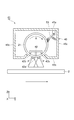
図1は、本発明の実施形態に係る成膜装置を示す概略断面構成図である。図1に示す成膜装置10は、スパッタリング法による成膜を行う装置であり、真空中でプラズマを発生させて、プラズマ中のプラスイオンを成膜材料(Inターゲット)に衝突させることで金属原子をはじき出し、基板上に付着させて成膜を行うものである。本実施形態の成膜装置10は、CIGS太陽電池を製造するスパッタ装置として利用することができる。
(Deposition system)
FIG. 1 is a schematic sectional view showing a film forming apparatus according to an embodiment of the present invention. A
成膜装置10は、成膜処理が行われる成膜室(真空チャンバー)11を備え、この成膜室11の入口側に基板仕込室(排気室)12が連結され、成膜室11の出口側に基板取出室(ベント室)13が連結されている。基板仕込室12は、大気圧下にある基板を装置内に取り込み、室内を真空とするためのチャンバーである。基板取出室13は、真空中にある基板を大気圧環境下へ取り出すためのチャンバーである。
The
以下、基板仕込室12、成膜室11、基板取出室13を区別しない場合には、チャンバー11〜13と記すこともある。これらのチャンバー11〜13は、真空容器によって構成され、チャンバー11〜13の出入口には、ゲートバルブGVが設けられている。ゲートバルブGVは、真空環境と大気圧環境とを隔てるための比較的大きな弁体を備えたバルブである。ゲートバルブGVの両側の圧力が等しいときにゲートバルブGVを開放することで隣接するチャンバー11〜13を連通させ、基板2を通過させる。
Hereinafter, when the
また、各チャンバー11〜13内には、基板2を搬送するための基板搬送ローラ14が設置されていると共に、基板2を加熱するためのヒータ15が設置されている。ヒータ15は、基板温度が例えば50℃〜350℃の範囲で一定となるように加熱する。
In each
さらに、排気室12およびベント室13には、ドライポンプ16が接続され、チャンバー11〜13には、TMP(ターボ分子ポンプ)17が接続されている。ドライポンプ16は、大気圧から10Paまでの排気をするための粘性流領域で使用されるポンプであり、TMP17は、10Pa以下の排気をするための分子流領域で使用されるポンプである。
Further, a
また、成膜装置10は、成膜室11内にスパッタリングターゲット21を保持するロータリースパッタリングカソード(以下、「ロータリーカソード」という)41を有する。スパッタリングターゲットであるInターゲット21は、成膜室11上部に配置され、基板2の搬送方向に沿って複数配置されている。これらのInターゲット21は、DC電源23に電気的に接続されている。DC電源23は、直流電力を供給する電源である。なお、ロータリーカソード41については後述する。
The
また、成膜装置10は、成膜室11内にアルゴンガスを供給するアルゴンガス供給装置30を備えている。アルゴンガス供給装置30は、成膜室11内へのアルゴンガス導入量を調節するマスフローコントローラ32、成膜室11に接続されてガスを導入するガス供給経路33を備えている。アルゴンガス導入量を調整するマスフローコントローラ32には、アルゴンガスを供給するアルゴンガスボンベ36が接続されている。アルゴンガス導入量を調節する流量調節器として、サーマルバルブ式、電磁弁式、ピエゾバルブ式の流量調整器を用いることができる。
The
(ロータリーカソード)
図2は、ロータリーカソードの横断面図であり、図3は、ロータリーカソードの縦断面図である。ロータリーカソード41は、成膜材料であるInターゲット21、Inターゲット21の表面に磁場を形成するためのマグネット42、Inターゲット21を回転可能に支持する支持部43、Inターゲット21を回転駆動させるための駆動部44、及びInターゲット21を収容する筐体45を備えている。ロータリーカソード41は、Inターゲット21の周面において、その周方向に磁気回路がInターゲット21に対して相対的に移動するマグネトロンスパッタリングカソードとして機能するものである。
(Rotary cathode)
FIG. 2 is a transverse sectional view of the rotary cathode, and FIG. 3 is a longitudinal sectional view of the rotary cathode. The
Inターゲット21は、円筒型のスパッタリングターゲットであり、所定の長さを有している。Inターゲット21は、基板搬送方向Yと交差する方向Xに延在している。マグネット42は、中央の磁石42aの両側に極性の異なる磁石42bが配置されている。マグネット42は、Inターゲット21の周面に磁場を形成するものである。マグネット42の磁極42a,42b間に形成された磁力線によって放電プラズマPが捕捉され、捕捉された放電プラズマ(マグネトロン放電プラズマ)は、エロージョン領域を形成する。また、Inターゲット21の内部には、Inターゲット21を冷却するための冷却手段(不図示)が設けられている。
The In
支持部43は、Inターゲット21の長手方向Yの両側からInターゲット21を支持するものである。支持部43は、例えば、筐体45に保持された軸受けを有し、Inターゲット21を回転可能に支持する。駆動部44は、Inターゲット21に回転駆動力を付与するものであり、駆動源として例えば電動モーターを用いることができる。支持部43は、筐体45を介して成膜室11のチャンバー壁(例えば天板)11aに固定されている。Inターゲット21の両端部を支持する一対の支持部43のうち、一方は、駆動部44を介して、筐体45に支持され、他方は、筐体45の側壁45dに直接支持されている。
The
筐体45は、例えば、箱型を成し、Inターゲット21を収容するものである。筐体45は、Inターゲット21の上部側の覆う天板45a、Inターゲット21の下部側を覆う底板45b、Inターゲット21の図示Y方向の両側を覆う側壁45c,45c、Inターゲット21の長手方向Xの両端部を外側から覆う側壁45d,45dを備えている。筐体45の底板45bには、Inターゲット21の長手方向Xに沿って開口部45eが形成されている。Inターゲット21の下部側の周面は、開口部を通じ基板2に対して露出されている。
The
また、筐体45の天板45aのInターゲット21に対向する面には、昇華した付着物を保持するための処理が施されている。そして、筐体45は、成膜室11のチャンバー壁11aに固定されている。例えば、筐体45の天板45aが、チャンバー壁11aに固定されている。
In addition, the surface of the top 45a of the
ここで、本実施形態のロータリーカソード41は、Inターゲット21の外周面に付着する付着物を加熱して昇華させて除去する除去手段51を備えている。除去手段51としては、電力が供給されて発熱するフィラメントを用いることができる。フィラメント51は、Inターゲット21の周面(外表面)と対向して配置され、Inターゲット21の回転方向Rの異なる位置に複数配置されている。本実施形態では、2本のフィラメント51が、Inターゲット21の回転方向Rにおいて配置されている。例えば、1本目のフィラメント51は、Inターゲット21の真上に配置され、2本目のフィラメント51は、Inターゲット21の回転方向Rにおいて、1本目のフィラメント51よりも、回転角度で、30度程度後方に配置されている。
Here, the
フィラメント51とInターゲット21の外表面との距離は、1〜50mm程度とすることが好ましい。また、フィラメント51は、Inターゲット21の長手方向Xに沿って延在し、筐体45に支持されている。フィラメント51は、Inターゲット21の長手方向Xの全長にわたって配置されている。フィラメント51は、例えば、成膜室11のチャンバー壁11a上に配置されたフィラメント電源52から電力が供給されて発熱する。発熱時におけるフィラメント51の温度は、例えば1000℃〜3000℃度程度である。フィラメント51の温度は、ターゲットとの距離、付着物の融点又は昇華点によって調整することが好ましい。
The distance between the
(成膜装置の動作)
次に、成膜装置10の動作について説明する。本実施形態に係る成膜装置10を用いた成膜基板の製造方法では、成膜材料であるInターゲットを用いてスパッタリング法により、基板2上に透明導電膜を成膜する成膜工程を行う。この成膜工程は、成膜装置10の成膜室11で実施される。
(Operation of the deposition system)
Next, the operation of the
まず、成膜工程の前処理として、ドライポンプ16及びTMP17を用いて、成膜室11内の排気を行い真空状態とする。成膜室11内の圧力は、例えば、5×10⁻⁴Pa以下とすることが好ましい。
First, as a pretreatment for the film forming process, the
次に、各ヒータ15をON状態として、その後各チャンバー11〜13内に導入される基板2の温度が50℃〜350℃の範囲内で一定となるように、ヒータ15における設定値を安定させる。
Next, each
成膜室11内の圧力が所望の真空圧力(5×10⁻⁴Pa以下)であることが確認された後に、アルゴンガス供給装置30のマスフローコントローラ32を駆動して、成膜室11内へのアルゴンガスの供給を開始する。マスフローコントローラ31,32は、成膜室11内の圧力を0.1Pa〜1Paの範囲内で任意の値に維持する。
After confirming that the pressure in the
その後、DC電源23をON状態として、成膜室11内にプラズマを発生させる。このとき、Inターゲット21は、回転方向Rに回転している。
Thereafter, the
成膜室11内のプラズマ放電が開始されると、Inターゲット21のスパッタリングが始まる。このとき、DC電源23は、Inターゲット21に対する電力密度を、1W/cm2〜40W/cm2の範囲内の任意の値に維持するように制御する。
When plasma discharge in the
ここで、成膜装置10では、スパッタリングの際に、フィラメント51が通電されて発熱している。フィラメント51は、例えば、1000℃〜3000℃度程度に維持されている。
Here, in the
Inターゲット21をスパッタリングする際には、Inターゲット21の外表面に副生生成物(ノジュール)が発生する。この副生生成物がInターゲット21の外表面に付着する付着物を形成する。この付着物は、例えば、黒色であり、Inターゲット21の外表面に比較的に弱い密着力で付着している。また、この付着物の熱伝導率は、比較的小さいものと考えられている。
When the
このような本実施形態のロータリーカソード41及びこれを備えた成膜装置10によれば、フィラメント51によって、Inターゲット21の外表面に付着した付着物を加熱して昇華させることができる。これにより、Inターゲット21の外表面に付着した付着物を取り除くことができる。そのため、従前のように付着物を取り除くためのスパッタリングを実行する必要がなくなり、付着物を取り除きながらもターゲットの消耗を抑えることができる。また、Inターゲット21の外表面に付着する付着物を除去することで、成膜速度の低下を抑制することができる。
According to the
また、本実施形態のロータリーカソード41及び成膜装置10によれば、ターゲット表面の付着物を装置の稼働中に除去することができるため、ターゲット表面の付着物除去のためのメンテナンス作業を軽減することができる。成膜装置10を停止させて、成膜室11の真空を破壊して清掃する必要がなくなる。従って、成膜装置10の連続運転を可能とし、生産効率の向上を図ることができる。また、ターゲット表面の付着物が除去された状態で、スパッタリング成膜を実行することができるため、付着物が付いたままでスパッタリング成膜を実行する場合と比較して、成膜のための消費電力の増加を抑えることができる。また、ターゲット表面の付着物が除去された状態で、スパッタリング成膜が実行されるため、ロット間のばらつきを抑えることができる。
Further, according to the
また、フィラメント51は、Inターゲット21の外表面と対向して配置され、Inターゲット21の回転方向Rの異なる位置に複数配置されているため、回転方向Rにおいて複数個所で付着物を除去することができる。例えば、前段のフィラメント51で除去できず、ターゲット表面に付着したままの残存付着物を、後段のフィラメント51の加熱により除去することができる。その結果、付着物を確実に取り除くことができ、成膜速度の低下を一層抑制することができる。
In addition, since the
また、Inターゲット21は、回転軸線方向Xに所定の長さを有し、フィラメント51は、回転軸線方向Xに複数配置されている構成でもよい。このように、Inターゲット21の回転軸線方向Xである長手方向に沿って、複数のフィラメント51が配置されていると、Inターゲット21の長手方向の位置に応じて、フィラメント51の作動状況を変化させることができる。例えば、Inターゲット21の長手方向の位置に応じて、Inターゲット21の消耗度合いが異なる場合には、Inターゲット21とフィラメント51との距離を変化させてもよい。また、Inターゲット21の長手方向の位置に応じて、付着物の付着量が異なる場合には、フィラメント51への供給電力を変えることで、フィラメント51の発熱量を変化させてもよい。
The In
また、本実施形態のロータリーカソード41及び成膜装置10は、Inターゲット21を収容する筐体45を備えているため、フィラメント51によって加熱され昇華された付着物を、筐体45に付着させて剥がれないようにすることができる。筐体45を備えていない構成であると、昇華して除去された付着物が、成膜室11の内壁面に付着することになり、成膜室11内が汚れることになり、さらに清掃が困難であるという問題が生じる。本実施形態では、昇華された付着物を付着させることが可能な筐体45を備えているため、成膜室11内の汚染を防止し、メンテナンス作業を容易にすることができる。筐体45に付着する付着物が増えた場合には、筐体45を取り替えることで、メンテナンス作業の簡素化を図ることができる。
In addition, since the
(第2実施形態)
次に、本発明の第2実施形態に係るロータリーカソード及びそれを備えた成膜装置について説明する。図1に示す成膜装置10の主要な装置構成は、第1及び第2実施形態で共通である。図4は、本発明の第2実施形態に係るロータリーカソードの横断面図であり、図5は、本発明の第2実施形態に係るロータリーカソードの縦断面図である。なお、第1実施形態と同様の説明は省略する。
(Second Embodiment)
Next, a rotary cathode according to a second embodiment of the present invention and a film forming apparatus including the same will be described. The main apparatus configuration of the
図4及び図5に示す第2実施形態のロータリーカソード41が、図2及び図3に示す第1実施形態のロータリーカソード41と違う点は、付着物を加熱して昇華させて除去する除去手段51に代えて、付着物を機械的に除去する除去手段53を備える点である。第2実施形態に係る成膜装置10は、Inターゲット21の外表面に付着した付着物を機械的に除去する除去手段53を有するロータリーカソード41を備えている。なお、「機械的に除去する」とは、「付着物と接触して(力学的に)付着物を取り除くことを意味している。」
The
除去手段53としては、付着物と接触して力学的に付着物を取り除くブラシを用いることができる。ブラシ53は、Inターゲット21の周面(外表面)と対向して配置され、ブラシ53の毛先が、Inターゲット21の周面と接触するように配置されている。ブラシ53は、例えば、Inターゲット21の回転により下降する側の周面と対向して配置されている。なお、ブラシ53は、Inターゲット21の回転により上昇する側の周面と対向して配置されている構成でもよい。また、ブラシ53は、Inターゲット21の上部側の周面と対向して配置されている構成でもよい。
As the removing
また、ブラシ53は、Inターゲット21の長手方向Xに沿って延在し、筐体45に支持されている。ブラシ53は、Inターゲット21の長手方向Xの全長にわたって配置されている。また、ブラシ53は、図5に示すように、Inターゲット21の長手方向X(回転軸線方向)に対して傾斜して配置されている。例えば、図示右側の端部(一端部)53aが、図示左側の端部53bと比較して下側となるように配置されている。なお、ブラシ53のX方向の中央部が、最も高い位置に配置され、X方向の両端部53a,53bが最も低い位置に配置されるように、傾斜させてもよい。
The
ブラシ53の長手方向の端部であり下方側の一端部の直下には、ブラシ53によって除去された付着物を収容する付着物受け皿54が設けられている。付着物受け皿54は、ブラシ53の端部53aから落下する付着物を回収可能な構成であればよい。ブラシ53の端部53a及びInターゲット21のX方向の端部は、基板2の幅方向Xの端部よりも外側に配置され、同様に、付着物受け皿54も基板2の幅方向Xの端部よりも外側に配置されている。付着物受け皿54は、筐体45の側壁45d又は底板45bに固定されている。このように付着物受け皿54は、筐体45に固定されていると、筐体45と一体として、付着物受け皿54を取外し又は取付けを行うことができる。
An adhering
このようなロータリーカソード41及びこれを備える成膜装置10によれば、Inターゲット21の外表面に付着した付着物が、Inターゲット21の回転に伴ってブラシ53と接触する。付着物は、ブラシ53と接触してInターゲット21の外表面より剥がれることになる。ブラシ53がInターゲット21の長手方向に対して傾斜して配置されているため、剥がれた付着物が下方へ移動し、ブラシ53の一端部53a側へ収集されて付着物受け皿54に回収される。
According to the
このように構成された第2実施形態のロータリーカソード41及びこれを備える成膜装置10は、ブラシ53によって、Inターゲット21の外表面に付着した付着物を機械的に力を作用させて除去することができる。そのため、従前のように付着物を取り除くためのスパッタリングを実行する必要がなくなり、付着物を取り除きながらもターゲットの消耗を抑えることができる。また、Inターゲット21の外表面に付着する付着物を除去することで、成膜速度の低下を抑制することができる。
The
第2実施形態のロータリーカソード41及び成膜装置10では、ターゲット表面の付着物を装置の稼働中に除去することができるため、ターゲット表面の付着物除去のためのメンテナンス作業を軽減することができる。成膜装置10を停止させて、成膜室11の真空を破壊して清掃する必要がなくなる。従って、成膜装置10の連続運転を可能とし、生産効率の向上を図ることができる。また、ターゲット表面の付着物が除去された状態で、スパッタリング成膜を実行することができるため、付着物が付いたままでスパッタリング成膜を実行する場合と比較して、成膜のための消費電力の増加を抑えることができる。また、ターゲット表面の付着物が除去された状態で、スパッタリング成膜が実行されるため、ロット間のばらつきを抑えることができる。
In the
以上、本発明をその実施形態に基づき具体的に説明したが、本発明は、上記実施形態に限定されるものではない。上記実施形態では、Inターゲット21を用いてスパッタリング成膜を実施しているが、ターゲットはIn(インジウム)に限定されず、例えば、ITO、AZO、GZO、Zn、Snなどその他のターゲットを用いる構成でもよい。
As mentioned above, although this invention was concretely demonstrated based on the embodiment, this invention is not limited to the said embodiment. In the above embodiment, sputtering film formation is performed using the
また、成膜装置10によって成膜されて製造される成膜基板は、CIGS太陽電池に使用されるものに限定されず、その他の太陽電池、タッチパネル、液晶ディスプレイなどに適用される基板でもよい。
Moreover, the film-forming board | substrate manufactured and formed by the film-forming
また、上記の実施形態では、昇華した付着物を付着させることが可能な筐体45を備える構成としているが、筐体に限らず、他の手段を採用することで、昇華した付着物を付着させてもよい。例えば、Inターゲット21の上方に、昇華した付着物を付着させるためのコールドトラップ(捕集体)を備える構成としてもよい。
In the above embodiment, the
また、上記の第1実施形態では、付着物を加熱して昇華させる除去手段として、フィラメント51を例示しているが、除去手段は、これに限定されず、例えば、ランプヒーターなどその他の加熱手段を備える構成としてもよい。また、上記実施形態では、付着物を加熱して昇華させる除去手段が、ターゲットの回転方向Rの異なる位置に複数配置されている構成としているが、回転方向Rに1つの除去手段が配置されている構成でもよく、3つ以上の除去手段が配置されている構成でもよい。
Moreover, in said 1st Embodiment, although the
また、上記の第2実施形態では、付着物を機械的に除去する除去手段として、ブラシ53を例示しているが、除去手段は、これに限定されず、例えば、へらなど、可撓性を有し付着物に適度な力を付与することで、ターゲット表面の付着物を剥離させる除去手段を備える構成でもよい。また、ターゲットの硬さを考慮して、ターゲットよりも軟らかい材質の除去手段を採用することで、ターゲットに傷が付くことを防止する。
Moreover, in said 2nd Embodiment, although the
また、上記の第2実施形態では、ブラシ53が、Inターゲット21の長手方向Xに対して傾斜して配置されている構成が開示されているが、ブラシ53が、Inターゲット21の長手方向Xに対して傾斜していない構成でもよい。また、例えば2本のブラシ53が、Inターゲット21の長手方向Xにおいて、中央側が端部側よりも下方に配置されるように傾斜して配置されている構成でもよい。例えば、一対のブラシ53がV字状に配置され、一対のブラシ53間の隙間に対応する位置に付着物受け皿54が配置されている構成でもよい。
Further, in the second embodiment, the configuration in which the
また、ロータリーカソード及びこれを備えた成膜装置は、付着物を加熱して昇華させる除去手段と、付着物を機械的に除去する除去手段との両方を備える構成でもよい。 Further, the rotary cathode and the film forming apparatus including the rotary cathode may be configured to include both a removing unit that heats and sublimates the deposit and a removing unit that mechanically removes the deposit.
また、除去手段の位置を調整する位置調整機構を備える構成とし、ターゲット表面と除去手段との距離を変更可能な構成としてもよい。これにより、ターゲットの消耗度合いに応じて、除去手段の位置を変えることができ、確実に付着物を除去することが可能である。 Moreover, it is good also as a structure provided with the position adjustment mechanism which adjusts the position of a removal means, and the structure which can change the distance of a target surface and a removal means. As a result, the position of the removing means can be changed according to the degree of consumption of the target, and the deposits can be reliably removed.
10…成膜装置(スパッタリング装置)、11…成膜室、12…基板仕込室、13…基板取出室、14…基板搬送ローラ、15…ヒータ、16…ロータリポンプ、17…TMP、21…Inターゲット(スパッタリングターゲット、成膜材料)、23…DC電源、30…アルゴンガス供給装置、32…マスフローコントローラ、33…ガス供給経路、41…ロータリースパッタリングカソード、45…筐体、51…フィラメント(除去手段)、53…ブラシ(除去手段)、54…受け皿。
DESCRIPTION OF
Claims (12)
前記ターゲットを収容する筐体と、
前記ターゲットの外表面に付着した付着物を加熱して昇華させて除去する除去手段と、を備え、
前記筐体には、前記ターゲットの一部を露出させるための開口部が形成されており、
前記除去手段は、前記筐体内に設けられていることを特徴とするロータリースパッタリングカソード。 A rotary sputtering cathode for sputtering by rotating a target, which is a cylindrical film-forming material, about a rotation axis,
A housing for housing the target;
Removing means for heating and sublimating and removing deposits attached to the outer surface of the target ;
The casing is formed with an opening for exposing a part of the target,
The rotary sputtering cathode , wherein the removing means is provided in the casing .
前記除去手段は、前記回転軸線方向に複数配置されていることを特徴とする請求項1又は2に記載のロータリースパッタリングカソード。 The target has a predetermined length in the rotation axis direction of the target,
The rotary sputtering cathode according to claim 1 or 2, wherein a plurality of the removing means are arranged in the rotation axis direction.
前記ターゲットを収容する筐体と、
前記ターゲットの外表面に付着した付着物を機械的に除去する除去手段と、を備え、
前記筐体には、前記ターゲットの一部を露出させるための開口部が形成されており、
前記除去手段は、前記筐体内に設けられていることを特徴とするロータリースパッタリングカソード。 A rotary sputtering cathode for sputtering by rotating a target, which is a cylindrical film-forming material, about a rotation axis,
A housing for housing the target;
Removing means for mechanically removing deposits attached to the outer surface of the target ,
The casing is formed with an opening for exposing a part of the target,
The rotary sputtering cathode , wherein the removing means is provided in the casing .
前記除去手段は、前記回転軸線方向に沿って延在し、前記回転軸線方向に対して傾斜して配置されていることを特徴とする請求項4に記載のロータリースパッタリングカソード。 The target has a predetermined length in the rotation axis direction of the target,
The rotary sputtering cathode according to claim 4, wherein the removing unit extends along the rotation axis direction and is inclined with respect to the rotation axis direction.
前記基板が導入されるチャンバーと、
前記チャンバー内に設置され、筒状の前記成膜材料であるターゲットを回転軸線回りに回転させてスパッタするためのロータリースパッタリングカソードと、を備え、
前記ロータリースパッタリングカソードは、前記ターゲットを収容する筐体と、前記ターゲットの外表面に付着した付着物を加熱して昇華させて除去する除去手段と、を有し、 前記筐体には、前記ターゲットの一部を露出させるための開口部が形成されており、
前記除去手段は、前記筐体内に設けられていることを特徴とする成膜装置。 A film forming apparatus for forming a film forming material on a substrate,
A chamber into which the substrate is introduced;
A rotary sputtering cathode installed in the chamber and sputtered by rotating a target, which is the tubular film-forming material, about a rotation axis;
The rotary sputtering cathode includes a housing that accommodates the target, and a removing unit that heats and sublimates and removes deposits attached to the outer surface of the target, and the housing includes the target. An opening is formed to expose a part of
The film removing apparatus, wherein the removing unit is provided in the housing .
前記除去手段は、前記回転軸線方向に複数配置されていることを特徴とする請求項7又は8に記載の成膜装置。 The target has a predetermined length in the rotation axis direction of the target,
The film forming apparatus according to claim 7, wherein a plurality of the removing units are arranged in the rotation axis direction.
前記基板が導入されるチャンバーと、
前記チャンバー内に設置され、筒状の前記成膜材料であるターゲットを回転軸線回りに回転させてスパッタするためのロータリースパッタリングカソードと、を備え、
前記ロータリースパッタリングカソードは、前記ターゲットを収容する筐体と、前記ターゲットの外表面に付着した付着物を機械的に除去する除去手段と、を有し、
前記筐体には、前記ターゲットの一部を露出させるための開口部が形成されており、
前記除去手段は、前記筐体内に設けられていることを特徴とする成膜装置。 A film forming apparatus for forming a film forming material on a substrate,
A chamber into which the substrate is introduced;
A rotary sputtering cathode installed in the chamber and sputtered by rotating a target, which is the tubular film-forming material, about a rotation axis;
The rotary sputtering cathode has a housing that accommodates the target, and a removing unit that mechanically removes deposits attached to the outer surface of the target ,
The casing is formed with an opening for exposing a part of the target,
The film removing apparatus, wherein the removing unit is provided in the housing .
前記除去手段は、前記回転軸線方向に沿って延在し、前記回転軸線方向に対して下方へ傾斜して配置されていることを特徴とする請求項10に記載の成膜装置。 The target has a predetermined length in the rotation axis direction of the target,
The film forming apparatus according to claim 10, wherein the removing unit extends along the rotation axis direction and is inclined downward with respect to the rotation axis direction.
Priority Applications (1)
| Application Number | Priority Date | Filing Date | Title |
|---|---|---|---|
| JP2011130301A JP5646397B2 (en) | 2011-06-10 | 2011-06-10 | Rotary sputtering cathode and film forming apparatus equipped with rotary sputtering cathode |
Applications Claiming Priority (1)
| Application Number | Priority Date | Filing Date | Title |
|---|---|---|---|
| JP2011130301A JP5646397B2 (en) | 2011-06-10 | 2011-06-10 | Rotary sputtering cathode and film forming apparatus equipped with rotary sputtering cathode |
Publications (2)
| Publication Number | Publication Date |
|---|---|
| JP2012255199A JP2012255199A (en) | 2012-12-27 |
| JP5646397B2 true JP5646397B2 (en) | 2014-12-24 |
Family
ID=47527013
Family Applications (1)
| Application Number | Title | Priority Date | Filing Date |
|---|---|---|---|
| JP2011130301A Expired - Fee Related JP5646397B2 (en) | 2011-06-10 | 2011-06-10 | Rotary sputtering cathode and film forming apparatus equipped with rotary sputtering cathode |
Country Status (1)
| Country | Link |
|---|---|
| JP (1) | JP5646397B2 (en) |
Families Citing this family (3)
| Publication number | Priority date | Publication date | Assignee | Title |
|---|---|---|---|---|
| JP5935028B2 (en) * | 2012-05-11 | 2016-06-15 | パナソニックIpマネジメント株式会社 | Sputtering equipment |
| JP7782975B2 (en) * | 2021-06-30 | 2025-12-09 | キヤノントッキ株式会社 | Sputtering apparatus and method for manufacturing electronic device |
| CN114164408A (en) * | 2021-12-07 | 2022-03-11 | 通威太阳能(安徽)有限公司 | Heterojunction solar cell production system and target cleaning mechanism |
Family Cites Families (6)
| Publication number | Priority date | Publication date | Assignee | Title |
|---|---|---|---|---|
| JPS63297555A (en) * | 1987-05-28 | 1988-12-05 | Fujitsu Ltd | Sputtering device |
| JPS6465258A (en) * | 1987-09-07 | 1989-03-10 | Nippon Atomic Ind Group Co | Vapor deposition-stabilizing device |
| JPH05263225A (en) * | 1992-03-18 | 1993-10-12 | Asahi Glass Co Ltd | Sputtering method |
| JPH06179966A (en) * | 1992-12-11 | 1994-06-28 | Ishikawajima Harima Heavy Ind Co Ltd | Thin film generator |
| JP2755138B2 (en) * | 1993-12-15 | 1998-05-20 | 日本電気株式会社 | Sputtering equipment |
| JP4157621B2 (en) * | 1998-07-21 | 2008-10-01 | 株式会社アルバック | Sputtering deposition system |
-
2011
- 2011-06-10 JP JP2011130301A patent/JP5646397B2/en not_active Expired - Fee Related
Also Published As
| Publication number | Publication date |
|---|---|
| JP2012255199A (en) | 2012-12-27 |
Similar Documents
| Publication | Publication Date | Title |
|---|---|---|
| JP2018532890A (en) | Apparatus for vacuum deposition on a substrate and method for masking a substrate during vacuum deposition | |
| US9966242B2 (en) | High throughput vacuum deposition sources and system | |
| JP5646397B2 (en) | Rotary sputtering cathode and film forming apparatus equipped with rotary sputtering cathode | |
| JPH10229058A (en) | Deposition chamber equipment with coating | |
| EP2827359B1 (en) | Cleaning method for thin-film processing applications and apparatus for use therein | |
| JP2022179487A (en) | Film deposition device and electronic device manufacturing method | |
| US8758579B2 (en) | Chamber for physical vapour deposition and door for a physical vapour deposition chamber | |
| JP6641472B2 (en) | Film forming method and sputtering apparatus | |
| US20180037984A1 (en) | Endblock for rotatable target with electrical connection between collector and rotor at pressure less than atmospheric pressure | |
| KR101430653B1 (en) | Inline sputtering apparatus | |
| JP5075662B2 (en) | Multi-target sputtering system | |
| KR20100071658A (en) | Apparatus for depositing thin film | |
| KR100674005B1 (en) | Sputtering Sources and Sputters with the Same | |
| CN112771200A (en) | Film forming method | |
| JP2004277799A (en) | Film forming apparatus and cleaning method thereof | |
| KR102142002B1 (en) | Method for depositing material on substrate, controller for controlling material deposition process, and apparatus for depositing layer on substrate | |
| JP6436829B2 (en) | Deposition equipment | |
| JP5935028B2 (en) | Sputtering equipment | |
| KR20170134740A (en) | METHOD AND APPARATUS FOR MAGNETONE SPUTTERING | |
| JP2005240182A (en) | System and method for continuous arc vapor deposition by a plurality of usable targets | |
| JP2004504495A (en) | Vacuum module (and its variants) and module system for coating substrates | |
| CN222581094U (en) | Cathode assembly and deposition apparatus | |
| CN118401696A (en) | Cathode assembly for sputter deposition, deposition apparatus and method | |
| JP3279762B2 (en) | Plasma processing equipment | |
| CN114182220A (en) | Sputtering apparatus and film forming method |
Legal Events
| Date | Code | Title | Description |
|---|---|---|---|
| A621 | Written request for application examination |
Free format text: JAPANESE INTERMEDIATE CODE: A621 Effective date: 20131008 |
|
| A977 | Report on retrieval |
Free format text: JAPANESE INTERMEDIATE CODE: A971007 Effective date: 20140307 |
|
| A131 | Notification of reasons for refusal |
Free format text: JAPANESE INTERMEDIATE CODE: A131 Effective date: 20140408 |
|
| A521 | Written amendment |
Free format text: JAPANESE INTERMEDIATE CODE: A523 Effective date: 20140604 |
|
| TRDD | Decision of grant or rejection written | ||
| A01 | Written decision to grant a patent or to grant a registration (utility model) |
Free format text: JAPANESE INTERMEDIATE CODE: A01 Effective date: 20141104 |
|
| A61 | First payment of annual fees (during grant procedure) |
Free format text: JAPANESE INTERMEDIATE CODE: A61 Effective date: 20141105 |
|
| R150 | Certificate of patent or registration of utility model |
Ref document number: 5646397 Country of ref document: JP Free format text: JAPANESE INTERMEDIATE CODE: R150 |
|
| LAPS | Cancellation because of no payment of annual fees |