JP5608397B2 - Tire vulcanizer and tire - Google Patents
Tire vulcanizer and tire Download PDFInfo
- Publication number
- JP5608397B2 JP5608397B2 JP2010067886A JP2010067886A JP5608397B2 JP 5608397 B2 JP5608397 B2 JP 5608397B2 JP 2010067886 A JP2010067886 A JP 2010067886A JP 2010067886 A JP2010067886 A JP 2010067886A JP 5608397 B2 JP5608397 B2 JP 5608397B2
- Authority
- JP
- Japan
- Prior art keywords
- tire
- circumferential direction
- sector mold
- along
- sector
- Prior art date
- Legal status (The legal status is an assumption and is not a legal conclusion. Google has not performed a legal analysis and makes no representation as to the accuracy of the status listed.)
- Expired - Fee Related
Links
Images


Landscapes
- Tires In General (AREA)
- Moulds For Moulding Plastics Or The Like (AREA)
- Heating, Cooling, Or Curing Plastics Or The Like In General (AREA)
Description
本発明は、セクターモールドなどの割りモールドを有するタイヤ加硫装置、及び、当該タイヤ加硫装置によって製造されるタイヤに関する。 The present invention relates to a tire vulcanizing apparatus having a split mold such as a sector mold, and a tire manufactured by the tire vulcanizing apparatus.
従来から、空気入りタイヤの製造工程には、生タイヤ(いわゆる、グリーンタイヤ)を加硫する加硫工程がある。この加硫工程においては、生タイヤのトレッド部を形成する円環状の複数のセクターモールドと、生タイヤのサイド部を形成するサイドモールドとを備えるタイヤ加硫装置が用いられる。このようなセクターモールドには、トレッド部にサイプを形成するためのブレードが設けられる(例えば、特許文献1参照)。 Conventionally, a pneumatic tire manufacturing process includes a vulcanizing process for vulcanizing a raw tire (so-called green tire). In this vulcanization step, a tire vulcanizing apparatus is used that includes a plurality of annular sector molds that form a tread portion of a green tire and a side mold that forms a side portion of the green tire. Such a sector mold is provided with a blade for forming a sipe in a tread portion (see, for example, Patent Document 1).
しかしながら、加硫後に前セクターモールドを径方向外側に移動させてブレードをタイヤのトレッド部から引き抜く場合に、ブレードがトレッド部に引っ掛かり、スムーズに引き抜くことが困難であった。この引っ掛かりによって、タイヤのトレッド部に設けられたサイプや該サイプが形成された陸部ブロックに損傷を与えるおそれがあった。 However, when the front sector mold is moved radially outward after vulcanization and the blade is pulled out from the tread portion of the tire, the blade is caught on the tread portion and it is difficult to pull it out smoothly. This catch may damage the sipe provided in the tread portion of the tire and the land block on which the sipe is formed.
そこで、本発明の目的は、加硫後のタイヤからセクターモールドのブレードをスムーズに引き抜くことにより、サイプや陸部ブロックへの損傷を抑制することができるタイヤ加硫装置、及び、当該タイヤ加硫装置によって製造されるタイヤを提供することにある。 Accordingly, an object of the present invention is to provide a tire vulcanizing apparatus capable of suppressing damage to a sipe or a land block by smoothly pulling out a sector mold blade from a vulcanized tire, and the tire vulcanizing. The object is to provide a tire manufactured by the device.
前述した課題を解決するため、本発明は次のような特徴を有している。本発明の第1の特徴は、弧状の形状を有し、未加硫の生タイヤ(タイヤTR)のトレッド部にトレッドパターンを形成する複数のセクターモールド(セクターモールド30)と、前記セクターモールドのそれぞれを、複数の前記セクターモールドによって形成される円環の中心(中心CL)と、前記セクターモールドの内周面における周方向中央(中点M)とを通るラジアル線(ラジアル線L)に沿って前記セクターモールドを拡縮させる拡縮機構(移動部32)と、を備えるタイヤ加硫装置(タイヤ加硫装置1)であって、前記円環の中心側に配置される前記セクターモールドの内周面に、前記円環の中心側に向かって突出するとともに前記セクターモールドの周方向に沿って延び、前記生タイヤのトレッド部にタイヤ周方向に延びる周方向サイプを形成するブレード(ブレード331〜333)を設け、前記セクターモールドの周方向に沿った分割数をnとした場合に、前記ブレードの周方向端縁(周方向端縁342,343)における前記円環の中心側の端部(傾斜部344,345)は、前記周方向端縁に対してθ≧180°/n傾斜することを要旨とする。
In order to solve the above-described problems, the present invention has the following features. A first feature of the present invention is that a plurality of sector molds (sector mold 30) having an arc shape and forming a tread pattern on a tread portion of an unvulcanized raw tire (tire TR), Each along a radial line (radial line L) passing through the center (center CL) of the ring formed by the plurality of sector molds and the circumferential center (middle point M) on the inner peripheral surface of the sector mold An expansion / contraction mechanism (moving part 32) for expanding and contracting the sector mold, and an inner peripheral surface of the sector mold disposed on the center side of the annular ring. And projecting toward the center side of the annular ring, extending along the circumferential direction of the sector mold, and extending in the tire circumferential direction on the tread portion of the green tire When blades (
通常、加硫後にセクターモールドを拡大させてブレードをタイヤのトレッド部から引き抜く場合に、ブレード(特に、ラジアル線Lから離れたブレード)がトレッド部に引っ掛かりやすく、スムーズに引き抜くことが困難である。特に、タイヤ周方向に延びるサイプを形成するブレードをスムーズに引き抜くことは困難である。 Normally, when the sector mold is expanded after vulcanization and the blade is pulled out from the tread portion of the tire, the blade (particularly, the blade away from the radial line L) is easily caught on the tread portion, and it is difficult to pull it out smoothly. In particular, it is difficult to smoothly pull out a blade that forms a sipe extending in the tire circumferential direction.
本発明では、ブレードの周方向端縁における径内側の端部に配置された傾斜部を前記周方向端縁に対してθ≧180°/nだけ傾斜させている。従って、セクターモールドを開く際に、特に引っ掛かりやすい径方向内側の端部をθだけタイヤ周方向内側に傾斜させているため、ブレードをスムーズに引き抜くことができる。これにより、セクターモールドを開く際に、タイヤのトレッド部に設けられたサイプや該サイプが形成された陸部ブロックに、アンダーカット等の損傷を与えることがなく、製造不良を好適に防止することができる。 In the present invention, the inclined portion disposed at the radially inner end of the circumferential edge of the blade is inclined by θ ≧ 180 ° / n with respect to the circumferential edge. Therefore, when opening the sector mold, the end on the radially inner side that is particularly easily caught is inclined inward in the tire circumferential direction by θ, so that the blade can be pulled out smoothly. Thereby, when opening the sector mold, the sipe provided in the tread portion of the tire and the land block on which the sipe is formed are not damaged such as an undercut, and manufacturing failure is suitably prevented. Can do.
本発明の第2の特徴は、本発明の第1の特徴に係り、前記ブレード(ブレード331〜333)は、前記複数のセクターモールド(セクターモールド30)のうち所定のセクターモールドに対して、前記所定のセクターモールドの周方向に沿って複数配設され、複数の前記ブレードの前記円環の中心(CL)側の端部(傾斜部344,345)の傾斜角θは、前記ラジアル線から周方向に沿って離れる方向に向かうにつれて徐々に大きく設定されることを要旨とする。
A second feature of the present invention is related to the first feature of the present invention, wherein the blades (
本発明の第3の特徴は、タイヤ周方向に沿って延びる主溝(主溝501〜503)によって形成された陸部(陸部511〜514)を備えるタイヤ(空気入りタイヤ500)であって、前記陸部には、前記陸部内で少なくとも一端が終端し、かつ前記主溝よりも細いサイプ(サイプ530)が形成され、前記サイプは、トレッド踏面から所定の位置までの範囲内に位置すある踏面側部分(踏面側部分530A)と、前記所定の位置から前記サイプの底部までの範囲内に位置し、前記サイプの延在方向に沿った長さが前記所定の位置から前記底部に向かうに連れて短くなる面取り部分(面取り部分530B)とを含むことを要旨とする。
The third feature of the present invention is a tire (pneumatic tire 500) including land portions (
本発明の第4の特徴は、本発明の第3の特徴に係り、前記面取り部分は、直線状に形成され、前記タイヤを製造するタイヤ加硫装置におけるセクターモールドの周方向に沿った分割数をnとした場合に、前記面取り部分のタイヤ径方向に対する傾斜角(θ530)は、180°/n以上に設定されることを要旨とする。 A fourth feature of the present invention relates to the third feature of the present invention, wherein the chamfered portion is formed in a straight line, and the number of divisions along the circumferential direction of the sector mold in the tire vulcanizing apparatus for manufacturing the tire. In this case, the inclination angle (θ530) of the chamfered portion with respect to the tire radial direction is set to 180 ° / n or more.
本発明の第5の特徴は、本発明の第4の特徴に係り、前記サイプは、タイヤ周方向に沿って所定間隔置きに複数形成され、前記傾斜角は、タイヤ周方向に隣接する他の前記面取り部分の傾斜角と異なることを要旨とする。 A fifth feature of the present invention relates to the fourth feature of the present invention, wherein a plurality of the sipes are formed at predetermined intervals along the tire circumferential direction, and the inclination angle is equal to another tire adjacent to the tire circumferential direction. The gist is that it is different from the inclination angle of the chamfered portion.
本発明の特徴によれば、加硫後のタイヤからセクターモールドのブレードをスムーズに引き抜くことにより、サイプや陸部ブロックへの損傷を抑制することができるタイヤ加硫装置、及び、当該タイヤ加硫装置によって製造されるタイヤを提供することができる。 According to the features of the present invention, a tire vulcanizing apparatus capable of suppressing damage to a sipe or a land block by smoothly pulling out a sector mold blade from a vulcanized tire, and the tire vulcanization A tire manufactured by the apparatus can be provided.
以下、本発明の実施形態に係るタイヤ加硫装置の詳細を図面に基づいて説明する。具体的には、(1)タイヤ加硫装置の全体構成、(2)タイヤ加硫装置の動作、(3)セクターモールドの構成、(4)ブレードの形状、(5)タイヤ加硫装置により製造される空気入りタイヤ、(6)変更例、(7)比較評価、(8)作用効果、(9)その他の実施形態について説明する。図面は模式的なものであり、各材料層の厚みやその比率などは現実のものとは異なることに留意すべきである。したがって、具体的な厚みや寸法は以下の説明を参酌して判断すべきものである。図面相互間においても互いの寸法の関係や比率が異なる部分が含まれている。 Hereinafter, details of a tire vulcanizing apparatus according to an embodiment of the present invention will be described with reference to the drawings. Specifically, (1) Overall configuration of tire vulcanizer, (2) Operation of tire vulcanizer, (3) Sector mold configuration, (4) Blade shape, (5) Manufactured by tire vulcanizer Pneumatic tires, (6) modified examples, (7) comparative evaluation, (8) operational effects, (9) other embodiments will be described. It should be noted that the drawings are schematic, and the thicknesses and ratios of the material layers are different from actual ones. Therefore, specific thicknesses and dimensions should be determined in consideration of the following description. Also included in the drawings are portions having different dimensional relationships and ratios.
(1)タイヤ加硫装置の全体構成
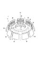
図1は、本発明の実施形態に係るタイヤ加硫装置を説明する構成図である。タイヤ加硫装置1は、基台支持部11、下基台12、上基台13、及び支持ロッド14を有する。基台支持部11は、基礎B上に設置される。下基台12は、方形状を有しており、基台支持部11によって支持される。下基台12は、基礎Bに対して水平に配置される。
(1) Overall configuration of tire vulcanizing apparatus FIG. 1 is a configuration diagram illustrating a tire vulcanizing apparatus according to an embodiment of the present invention. The tire vulcanizing apparatus 1 includes a
支持ロッド14は、所定の長さを有する。支持ロッド14は、上下方向に沿って配置される。タイヤ加硫装置1は、4本の支持ロッド14を有する。4本の支持ロッド14は、下基台12の四隅にそれぞれ配置される。
The
支持ロッド14の下基台12との連結部分の逆の端部には、上基台13が取り付けられる。4本の支持ロッド14は、上基台13を支持している。
An
上基台13は、下基台12と略同一形状を有する。上基台13は、下基台12と所定の間隔を隔てている。上基台13には、後述するピストンロッド41、ガイドロッド43が挿通される開口部13a,13bが形成される。上基台13は、基礎Bに対して水平に配置される。
The
下基台12の中央部には、開口部12aが設けられている。開口部12aには、ブラダー装置20が設置される。ブラダー装置20は、上下方向に昇降可能に設置される。
An
ブラダー装置20は、ブラダー21と、ピストンロッド22と、制御シリンダー23と、給排管24とを有する。
The
ブラダー21は、可撓性材料(例えば、ブチルゴム)により形成される。ブラダー21の上側の端部21aは、上部クランプ25に固定される。ブラダー21の下側の端部21bは、下部クランプ26に固定される。ブラダー21の外側には、タイヤTRが載置される。ブラダー21には、加熱及び加圧された流体Rが送り込まれる。ブラダー21は、送り込まれた流体RによってタイヤTRの内側で膨張し、ドーナツ状になる。
The
ピストンロッド22の中心軸は、上下方向、すなわち、基礎Bに対して垂直方向に沿って配置される。ピストンロッド22の下端部には、制御シリンダー23が連結される。ピストンロッド22及び制御シリンダー23は、下基台12の略中心に沿って配置されている。
The central axis of the
制御シリンダー23は、ピストンロッド22の下方に設けられる。制御シリンダー23は、ピストンロッド22の動きを制御する。すなわち、制御シリンダー23は、ピストンロッド22を上下方向(矢印V)に沿って移動させる。
The
給排管24は、下部クランプ26に連結されている。給排管24は、ブラダー21内部に、所定の温度、所定の圧力に設定された流体Rを導入する。または、導入された流体Rを排出する。流体Rは、加熱・加圧された蒸気、窒素ガス等である。給排管24は、図示しない導入装置に接続されている。
The supply /
タイヤ加硫装置1は、セクターモールド30及び下側サイドモールド31を有する。セクターモールド30及び下側サイドモールド31は、下基台12のブラダー装置20の周囲に配置される。
The tire vulcanizing apparatus 1 has a
セクターモールド30は、弧状の形状を有し、タイヤTRのトレッド部にトレッドパターンを形成するモールドである。
The
下側サイドモールド31は、タイヤTRのサイドウォール部を型付けする。下側サイドモールド31は、タイヤTRの一方のサイドウォール部を成形するためのモールドである。セクターモールド30及び下側サイドモールド31には、ヒータ等の加熱部(不図示)が設けられる。
The
タイヤ加硫装置1は、セクターモールド30を移動させる移動部32を有する。移動部32は、所定の可動レンジを有する。移動部32は、セクターモールド30をタイヤ加硫装置1に載置されるタイヤTRのタイヤ径方向に沿って移動させる(矢印H)。図1では、セクターモールド30は、可動レンジのタイヤ径方向の外側限に位置している。すなわち、移動部32は、拡縮機構を構成する。
The tire vulcanizing apparatus 1 includes a moving
タイヤ加硫装置1は、プレート40を有する。プレート40は、下基台12と上基台13との間に配置される。プレート40の四隅には、支持ロッド14が挿通される。
The tire vulcanizing apparatus 1 has a
タイヤ加硫装置1は、プレート40を昇降させるための機構として、ピストンロッド41、制御シリンダ42、ガイドロッド43とを有する。ピストンロッド41は、上基台13の略中央部に設けられた開口部13aに挿通される。また、ガイドロッド43は、上基台13の所定位置に設けられた開口部13bに挿通される。
The tire vulcanizing apparatus 1 includes a
ピストンロッド41は、プレート40の略中央部に連結される。ガイドロッド43は、プレート40の所定位置に連結される。ピストンロッド41は、制御シリンダー42によって、基礎Bに対して上下方向(矢印V)に移動可能とされる。従って、プレート40は、支持ロッド14に沿って移動される。図1では、プレート40は、垂直方向の上限に位置している。
The
プレート40の下面には、アウターリング34が配置される。アウターリング34は、円環状を有する。リング内径は、複数のセクターモールド30を組み合わせた際のセクターモールド30の外郭と略同径である。また、アウターリング34のリング中心は、ブラダー装置20の中心軸と同軸である。アウターリング34は、セクターモールド30の拡縮範囲を規制する。
An
タイヤ加硫装置1は、サイドプレート44を有する。サイドプレート44は、支持ロッド45を介してプレート40に取り付けられる。サイドプレート44には、上側サイドモールド33が設けられる。上側サイドモールド33は、タイヤTRのサイドウォールを型付けする。
The tire vulcanizing apparatus 1 has a
上側サイドモールド33は、未加硫の生タイヤTRのタイヤ径方向に沿ったタイヤ側面部を形成するモールドである。上側サイドモールド33は、加熱部を有する(不図示)。
The
本実施形態において、基台支持部11、下基台12、上基台13、支持ロッド14、プレート40、ピストンロッド41は、コンテナ部を構成する。すなわち、プレート40に配置されるアウターリング34、下基台12に移動可能に設置されるセクターモールド30は、コンテナ部に含まれる。
In this embodiment, the
(2)タイヤ加硫装置の動作
次いで、タイヤ加硫装置1の動作を説明する。図2,図3は、セクターモールド30を示す斜視図である。セクターモールド30は、タイヤTRのトレッド部の型付けを行うためのモールドであり、タイヤ周方向に沿って、複数個(例えば、9個)に分割される。セクターモールド30は、タイヤ加硫装置1の下基台12上に、移動部32を介して円弧状に配置される。
(2) Operation of Tire Vulcanizing Device Next, the operation of the tire vulcanizing device 1 will be described. 2 and 3 are perspective views showing the
図2は、未加硫のタイヤTRを装置内部に載置するとき、又は加硫後のタイヤTRを装置内部から取り出すときの各セクターモールド30の配置状態を示す図である。図3は、加硫時における各セクターモールド30の配置状態を示す図である。図2に示す矢印Vの方向は、図1の矢印Vの方向と同じである。
FIG. 2 is a view showing an arrangement state of each
図2,3に示すように、セクターモールド30の内周面における周方向Dの中点Mと、複数のセクターモールド30によって形成される円環の中心線CLとを通るラジアル線Lに沿って拡縮する。すなわち、セクターモールド30は、H方向に沿って拡縮する。
As shown in FIGS. 2 and 3, along a radial line L that passes through the midpoint M of the circumferential direction D on the inner peripheral surface of the
未加硫のタイヤである生タイヤTRは、タイヤ加硫装置1のブラダー装置20の周りに載置される。未加硫のタイヤTRのカーカス部(不図示)は、上部クランプ25,下部クランプ26に固定される。
The raw tire TR, which is an unvulcanized tire, is placed around the
タイヤ加硫装置1は、制御シリンダー42によってピストンロッド41を押し下げる。これにより、プレート40が下降する。すなわち、プレート40の下側面に取り付けられたアウターリング34が下基台12に向けて下降する。また、プレート40の下降と共にサイドプレート44に設けられた上側サイドモールド33が下降する。
The tire vulcanizing apparatus 1 pushes down the
セクターモールド30は、アウターリング34の下降動作に同期して、タイヤ径方向の外側から中心に向かって移動する。アウターリング34は、セクターモールド30に当接し、更に可動下限まで下降する。
The
(3)セクターモールドの構成
次に、セクターモールドの構成を説明する。図4は、セクターモールド30の内周面の一部を示す斜視図である。
(3) Configuration of Sector Mold Next, the configuration of the sector mold will be described. FIG. 4 is a perspective view showing a part of the inner peripheral surface of the
図4に示すように、セクターモールド30のトレッドパターン形成面30aには、トレッド部のブロックを形成するブロック形成部301,302,303と、ショルダー部分を形成するショルダー形成部304,305とが形成される。ブロック形成部301,302,303、及びショルダー形成部304,305は、トレッドパターン形成面30aよりも凹んでいる。
As shown in FIG. 4, the tread
ブロック形成部301,302,303は、それぞれ底部301a,302a,303aを有する。ショルダー形成部304,305は、それぞれ底部304a,305aを有する。底部301a乃至305aは、タイヤTRのトレッド部にトレッド踏面を形成する。
The
タイヤ幅方向に隣接するブロック形成部301とブロック形成部302との間には、壁部311が形成される。また、ブロック形成部301とブロック形成部303との間には、壁部312が形成される。タイヤ幅方向に隣接するブロック形成部302とショルダー形成部304との間には、壁部313が形成される。また、ブロック形成部303とショルダー形成部305との間には、壁部314が形成される。
A
壁部311乃至314は、トレッド部にタイヤ周方向に延びる主溝を形成する。壁部311乃至314の高さが主溝の深さを決定する。
The
タイヤ周方向に隣接するブロック形成部301の間には、壁部321が形成される。タイヤ周方向に隣接するブロック形成部302の間には、壁部322が形成される。タイヤ周方向に隣接するブロック形成部303の間には、壁部323が形成される。タイヤ周方向に隣接するショルダー形成部304の間には、壁部324が形成される。タイヤ周方向に隣接するショルダー形成部305の間には、壁部325が形成される。
A
壁部321乃至325は、トレッド部にタイヤ幅方向に延びる横溝を形成する。壁部321乃至325の高さが横溝の深さを決定する。
The
セクターモールド30は、タイヤTRのトレッド部にサイプを形成するブレード331乃至335を有する。ここで、サイプとは、溝幅が0.4〜0.7mm程度の溝である。
The
ブレード331乃至335の各々は、ブロック形成部301乃至303の底部301a乃至303aに植設される。ブロック形成部301〜303の底部301a〜303aからブレード331〜333の内周側の端部までの高さがタイヤ側のサイプの深さになる。
Each of the
(4)ブレードの形状
次いで、本実施形態に係るブレード332の形状について図5〜図6を用いて説明する。図5は、本発明の実施形態に係るブレードを概略的に示す平面図である。図6は、本発明の実施形態に係るブレードの端部の傾斜角を説明する図である。なお、前述した図4におけるブレード332の形状を説明するが、他のブレード331,333の形状も同様である。
(4) Shape of Blade Next, the shape of the
図5及び図6に示すように、ブレード332の周囲は、セクターモールド30の外周側に配置された円弧状の外周端縁340と、内周側に配置された内周端縁341と、これらの外周端縁340および内周端縁341の周方向両側に配置された周方向端縁342,343および傾斜部344,345と、から画成されている。この傾斜部344,345は、ブレード332の周方向両側における径方向内側(円環の中心CL側)の端部において、周方向端縁342,343に対して直線状でかつ傾斜した状態で配置されている。
As shown in FIGS. 5 and 6, the periphery of the
図6に示すように、セクターモールド30の内周面における周方向Dの中点Mと、複数のセクターモールド30によって形成される円環の中心線CLとを通るラジアル線Lに沿った方向H0〜H2に沿って、前記セクターモールド30は拡縮するように構成されている。なお、H0はブレード332の周方向中央における拡縮方向であり、H1,H2はブレード332の周方向端部における拡縮方向であり、これらH0〜H2は全て平行である。また、前記周方向端縁342,343は、CLを中心とする円の半径方向に沿って延びており、傾斜部344,345は、周方向端縁342,343に対して周方向内側にθだけ傾斜して面取りされている。この傾斜角θは、セクターモールド30の分割数をnとした場合に、180°/n以上に設定されている。
As shown in FIG. 6, a direction H0 along a radial line L that passes through the midpoint M of the circumferential direction D on the inner peripheral surface of the
次に、このθ≧180°/nについて図6を用いて説明する。図6において、説明を判り易くするために、セクターモールド30の周方向の全領域に亘ってブレード332が延設されているとする。また、セクターモールド30の周方向Dに沿った分割数はnとする。
Next, this θ ≧ 180 ° / n will be described with reference to FIG. In FIG. 6, it is assumed that the
CLを中心とする円の円周角をαとし、中点Mを通る線Lによって円周角αを2分割するとα/2である。α=360°/nであるため、α/2=180°/nである。つまり、n分割されたモールド中のセクターモールド30は、(360/n)°の角度を有し、セクターモールド30に垂直に延設されたブレード332は、最大(180/n)°の角度で移動する。従って、θを、このα/2=180°/n以上に設定すれば、セクターモールド30をH0〜H2の方向に開く際に、ブレード332をタイヤのサイプからスムーズに引き抜くことができる。
When the circumferential angle of a circle centered at CL is α, and the circumferential angle α is divided into two by a line L passing through the midpoint M, it is α / 2. Since α = 360 ° / n, α / 2 = 180 ° / n. That is, the
(5)タイヤ加硫装置により製造される空気入りタイヤ
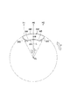
次いで、上述したタイヤ加硫装置1により製造される空気入りタイヤ500のトレッドパターンについて、図7〜図8を参照しながら説明する。図7は、本発明の実施形態に係る空気入りタイヤ500のトレッドパターンを示す展開図である。図8は、本発明の実施形態に係る空気入りタイヤ500の一部断面図(図7のA−A断面図)である。
(5) Pneumatic tire manufactured by tire vulcanizing apparatus Next, a tread pattern of the
図7及び図8に示すように、空気入りタイヤ500では、タイヤ周方向TDに沿って延びる主溝501〜503によって、タイヤ周方向TDに沿って延びるリブ状の陸部511〜514が形成されている。
As shown in FIGS. 7 and 8, in the
陸部511,514には、トレッド幅方向TWに延びる横溝520が形成されている。陸部512,513には、主溝501〜503よりも細いサイプ530と、トレッド幅方向TWに沿って凹む切欠部540とが形成される。
A
サイプ530は、タイヤ周方向TDに沿って所定間隔置きに複数形成される。サイプ530の一端は、陸部512,513内で終端し、サイプ530の他端は、切欠部540に開口する。サイプ530は、踏面側部分530Aと、面取り部分530Bとを含む。
A plurality of
踏面側部分530Aは、トレッド踏面531から所定の位置Pまでの範囲内に位置する。なお、所定の位置Pは、図面ではサイプ530の深さのほぼ半分の位置であるが、任意に設定できる。踏面側部分530Aでは、サイプ530の延在方向(すなわち、タイヤ周方向TD)に沿った長さL530Aが一定である。
The
面取り部分530Bは、所定の位置Pからサイプ530の底部532までの範囲内に位置する。面取り部分530Bでは、サイプ530の延在方向に沿った長さL530Bが所定の位置Pから底部に向かうに連れて徐々に短くなる。
The chamfered
面取り部分530Bの端縁は、直線状に形成されている。また、上述したセクターモールド30の周方向に沿った分割数をnとした場合に、面取り部分530Bの端縁のタイヤ径方向TRに対する傾斜角θ530は、180°/n以上に設定される。
The edge of the chamfered
なお、空気入りタイヤ500は、空気ではなく、窒素ガスなどの不活性ガスが充填されてもよい。また、空気入りタイヤ500は、空気や窒素ガスなどが充填されないソリッドタイヤでもあってもよい。
The
(6)変更例
次いで、本実施形態の変更例を図9を用いて説明する。図9は、本発明の変更例に係るブレードを概略的に示す平面図である。
(6) Modification Example Next, a modification example of the present embodiment will be described with reference to FIG. FIG. 9 is a plan view schematically showing a blade according to a modified example of the present invention.
上述した実施形態では、1つのセクターモールド30に対して1つのブレードが設けられる。また、1つのブレード332には、2つの傾斜部344,345が設けられる。これに対して、変更例では、1つのセクターモールド400に対して複数のブレードが設けられる。また、1つのブレードには、1つの傾斜部が設けられる。
In the embodiment described above, one blade is provided for one
具体的には、図9に示すように、ブレードは、複数のセクターモールドのうちの一つのセクターモールド400に対して、一つのセクターモールド400の周方向に沿って複数配設される。なお、変更例では、一つのセクターモールド400に対して5個のブレード401〜405が配設される。
Specifically, as shown in FIG. 9, a plurality of blades are arranged along the circumferential direction of one
これらのブレード401〜405の径内側の端部411〜415の傾斜角θ1〜θ5は、前記周方向に隣接する他の傾斜角θ1〜θ5と異なる。本実施形態では、ブレードの前記径内側の端部411〜415の傾斜角θ1〜θ5は、セクターモールドの周方向外側に向かうにつれて徐々に大きく設定される。即ち、θ1=θ5>θ2=θ4>θ3の大小関係に設定される。
The inclination angles θ1 to θ5 of the inner ends 411 to 415 of the
一つのセクターモールド400においては、周方向外側の部位の方が周方向内側よりもセクターモールド400を開く際にブレードが引っ掛かりやすいため、周方向外側の傾斜角をより大きく設定される。
In one
このようなブレードを備えるタイヤ加硫装置では、面取り部分520Bの傾斜角がタイヤ周方向に隣接する他の面取り部分520Bの傾斜角と異なるサイプ530が形成された空気入りタイヤを製造できる。
In a tire vulcanizing apparatus including such a blade, a pneumatic tire in which a
(7)比較評価
次いで、本発明の効果を検証するため、実施例と従来例および比較例とを比較評価した。なお、比較評価に用いたタイヤは、タイヤサイズが195/80R15 および 107/105Lである。
(7) Comparative Evaluation Next, in order to verify the effects of the present invention, the Examples were compared with the conventional examples and the comparative examples. The tires used for comparative evaluation have tire sizes of 195 / 80R15 and 107 / 105L.
従来例、比較例1〜4、実施例1〜2に係るタイヤを用いて、サイプ底の底上げ量、傾斜部603の傾斜角θ、ブレード600の抜け性、実車制動試験、およびヒールアンドトウ段差量を検証した。
Using tires according to conventional examples, comparative examples 1 to 4, and examples 1 and 2, the sipe bottom raising amount, the inclination angle θ of the
なお、実施例1,2のタイヤは、上述した図7に示すトレッドパターンである。この実施例1,2のタイヤに形成されたサイプ530は、図10に示すブレード600で形成された。すなわち、1つのブレードに対して、1つの傾斜部が設けられる。
The tires of Examples 1 and 2 have the tread pattern shown in FIG. The
具体的には、ブレード600は、セクターモールドの植設溝に挿入される基部601と、セクターモールドの内周面から内周側に突出する成形部602とからなる。基部601には、ブレード600をセクターモールドに取り付ける取付孔604が形成されている。また、成形部602の周方向端部には、基部605の周方向端縁に対して角度θ603だけ傾斜する傾斜部603が形成されている。なお、ブレード600における傾斜部603の傾斜角θ603は、実施例1では20°、実施例2では25°に設定した。
Specifically, the
その他の従来例、比較例1〜4に係るタイヤは、実施例1,2のタイヤのトレッドパターンと同様であり、サイプの構成のみことなっている。なお、各タイヤの構成や測定結果については、表1に示す通りである。

表1に示す底上げ量とは、従来例に係るサイプの溝深さに対して底上げした長さを従来例に対する相対値で示している。傾斜角とは、図10の傾斜部の傾斜角θである。ブレードの抜け性とは、ブレードを引き抜いた後の製品タイヤの表面における傷や損傷の有無を目視で確認した結果、傷等があった場合は×、なかった場合は○とした。実車制動試験とは、専用コースにおける全5回の制動距離の平均値を指数化し、数値が大きいほど良好であることを示す。なお、走行路面は、水深が2.0mm、空気圧が車両設定値、荷重は車両重量200kgに乗員1名の体重を加えた重さである。時速80kmで走行しているときにブレーキをかけたときの制動距離を示す。なお、ヒールアンドトウ段差量とは、摩耗実地試験10000km走行後において、一つの陸部ブロックにおけるタイヤ周方向に沿った両端の段差量を示す。 The raised amount shown in Table 1 indicates the length raised with respect to the groove depth of the sipe according to the conventional example as a relative value with respect to the conventional example. The inclination angle is the inclination angle θ of the inclined portion in FIG. With regard to the detachability of the blade, the result of visually confirming the presence or absence of scratches or damage on the surface of the product tire after the blade was pulled out was evaluated as x when scratches were found, and ◯ when there was no scratches. In the actual vehicle braking test, the average value of all five braking distances in the dedicated course is indexed, and the larger the value, the better. The traveling road surface has a water depth of 2.0 mm, an air pressure of a vehicle set value, and a load obtained by adding the weight of one passenger to the vehicle weight of 200 kg. The braking distance when the brake is applied while traveling at 80 km / h is shown. Note that the heel and toe step amount indicates the step amount at both ends along the tire circumferential direction in one land block after running at an actual wear test of 10,000 km.
表1に示すように、実施例1,2は、ブレードの抜け性、実車制動試験、ヒールアンドトウ段差量の全ての評価において、従来例および比較例1〜4よりも良好な結果を得た。特に、傾斜角が20〜30(特に、27°)であることが好ましいも判った。 As shown in Table 1, Examples 1 and 2 obtained better results than the conventional examples and Comparative Examples 1 to 4 in all evaluations of blade slippage, actual vehicle braking test, and heel and toe level difference. . In particular, it has been found that the inclination angle is preferably 20 to 30 (particularly 27 °).
(8)作用効果
本実施形態では、セクターモールド30の分割数をnとした場合に、ブレード331〜333の周方向端縁342,343における径内側の端部に配置された傾斜部344,345は、周方向端縁342,343に対してθ≧180°/n傾斜する。
(8) Effects In the present embodiment, when the number of divisions of the
通常、加硫後にセクターモールドを拡大させてブレードをタイヤのトレッド部から引き抜く場合に、ブレードがトレッド部に引っ掛かりやすく、スムーズに引き抜くことが困難である。特に、タイヤ周方向に延びるサイプを形成するブレードをスムーズに引き抜くことは困難である。 Usually, when the sector mold is expanded after vulcanization and the blade is pulled out from the tread portion of the tire, the blade is easily caught on the tread portion, and it is difficult to pull it out smoothly. In particular, it is difficult to smoothly pull out a blade that forms a sipe extending in the tire circumferential direction.
本実施形態では、ブレード331〜333の周方向端縁342,343における径内側の端部に配置された傾斜部344,345を前記周方向端縁342,343に対してθ≧180°/nだけ傾斜させている。従って、セクターモールド30を開く際に、特に引っ掛かりやすい径内側の端部をθだけタイヤ周方向内側に傾斜させているため、ブレードをスムーズに引き抜くことができる。これにより、セクターモールド30を開く際に、タイヤのトレッド部に設けられたサイプや該サイプが形成された陸部ブロックにアンダーカット等の損傷を与えることがなく、製造不良を好適に防止することができる。
In the present embodiment, the
本実施形態では、ブレード401〜405の前記径内側の端部411〜415の傾斜角θは、ラジアル線Lから周方向に沿って離れる方向(すなわち、セクターモールド30の周方向外側)に向かうにつれて徐々に大きく設定される。
In the present embodiment, the inclination angle θ of the radially
セクターモールド30の内周面における周方向中央近傍に位置するブレード331は、セクターモールド30の移動方向H、すなわちラジアル線Lに沿って設けられる。一方、セクターモールドの内周面における周方向端部に位置するブレード332,333は、ラジアル線Lから離れて設けられるため、ラジアル線Lに対して傾斜した状態で設けられる。このため、所定のセクターモールド30では、周方向の両側に近づくにつれてブレードが抜けにくくなる。
The
従って、ブレード401〜405の前記径内側の端部411〜415の傾斜角θがセクターモールド30の周方向外側に向かうにつれて徐々に大きく設定されることにより、ブレード401〜405の全てをスムーズに引き抜くことができる。また、空気入りタイヤ側においては、サイプの溝の容積を確保しつつ製造不良を抑制することができる。
Accordingly, the
本実施形態では、タイヤ加硫装置1では、踏面側部分530Aと面取り部分530Bとを含むサイプ530が形成された空気入りタイヤ500を製造できる。このため、陸部512,513への損傷を抑制することができるとともに、陸部512,513の剛性を向上させることができる。従って、タイヤ加硫装置1により製造される空気入りタイヤ500では、陸部の剛性低下に起因する性能(例えば、耐摩耗性や制動性能)を改善できる。
In the present embodiment, the tire vulcanizing apparatus 1 can manufacture the
(9)その他の実施形態
なお、前述した実施の形態の開示の一部をなす論述および図面はこの発明を限定するものであると理解すべきではない。この開示から当業者には様々な代替実施の形態、実施例および運用技術が明らかとなろう。
(9) Other Embodiments It should not be understood that the description and drawings that constitute part of the disclosure of the above-described embodiments limit the present invention. From this disclosure, various alternative embodiments, examples and operational techniques will be apparent to those skilled in the art.
具体的には、タイヤ加硫装置1は、タイヤ周方向に沿ったサイプを形成するものとして説明したが、これに限定されるものではなく、トレッド面視においてタイヤ周方向に対して傾斜したサイプを形成してもよい。つまり、サイプ530は、必ずしもタイヤ周方向に沿って形成される必要はなく、トレッド面視においてタイヤ周方向に対して傾斜した状態で形成されていてもよい。
Specifically, the tire vulcanizing apparatus 1 has been described as forming a sipe along the tire circumferential direction, but is not limited to this, and the sipe that is inclined with respect to the tire circumferential direction in a tread surface view. May be formed. That is, the
また、傾斜部344,345は、直線状に形成されるものとして説明したが、これに限定されるものではなく、湾曲状や屈曲状に形成されていてもよい。つまり、面取り部分530Bは、必ずしも直線状に形成される必要はなく、湾曲状や屈曲状に形成されていてもよい。なお、このような場合、傾斜角θは、周方向端縁342,343と傾斜部344,345との境目(つまり、踏面側部分530Aと面取り部分530Bとの境目(所定の位置P))で測定されるものとする。
In addition, although the
また、空気入りタイヤ500のトレッドパターンについては、実施形態で説明したものに限定されるものではなく、主溝や陸部の数や形状を目的に応じて適宜変更してもよいことは勿論である。
Further, the tread pattern of the
このように、本発明は、ここでは記載していない様々な実施の形態などを含むことは勿論である。したがって、本発明の技術的範囲は、上述の説明から妥当な特許請求の範囲に係る発明特定事項によってのみ定められるものである。 As described above, the present invention naturally includes various embodiments that are not described herein. Therefore, the technical scope of the present invention is defined only by the invention specifying matters according to the scope of claims reasonable from the above description.
1…タイヤ加硫装置
30…セクターモールド
331〜333…ブレード
344,345…傾斜部
500…空気入りタイヤ
530…サイプ
530A…踏面側部分
530B…面取り部分
DESCRIPTION OF SYMBOLS 1 ...
Claims (5)
前記セクターモールドのそれぞれを、複数の前記セクターモールドによって形成される円環の中心と、前記セクターモールドの内周面における周方向中央とを通るラジアル線に沿って前記セクターモールドを拡縮させる拡縮機構と、を備えるタイヤ加硫装置であって、
前記円環の中心側に配置される前記セクターモールドの内周面に、前記円環の中心側に向かって突出するとともに前記セクターモールドの周方向に沿って延び、前記生タイヤのトレッド部にタイヤ周方向に延びる周方向サイプを形成するブレードを設け、
当該ブレードは、前記円環の中心側に向かって直線状に突出形成された周方向端縁と、当該周方向端縁から延設され、前記セクターモールドの周方向に沿った分割数をnとした場合に、前記周方向端縁に対して傾斜角θ≧180°/nだけブレードの中央側に傾斜するように面取りされた直線状の傾斜部とを有するタイヤ加硫装置。 A plurality of sector molds having an arc shape and forming a tread pattern on a tread portion of an unvulcanized raw tire;
An expansion / contraction mechanism that expands / contracts each of the sector molds along a radial line that passes through the center of an annular ring formed by the plurality of sector molds and the center in the circumferential direction of the inner peripheral surface of the sector mold; A tire vulcanizing apparatus comprising:
The inner surface of the sector mold disposed on the center side of the annular ring projects toward the center side of the annular ring and extends along the circumferential direction of the sector mold, and the tire is attached to the tread portion of the raw tire. Provide a blade that forms a circumferential sipe extending in the circumferential direction,
The blade has a circumferential edge formed linearly projecting toward the center of the ring, and extends from the circumferential edge. The number of divisions along the circumferential direction of the sector mold is n. when the tire vulcanizer having a front Symbol circumferential end linear slope portion which is chamfered so as to be inclined toward the center of the inclination angle θ ≧ 180 ° / n by the blades to the edge.
前記複数のブレードにおける前記傾斜角θは、前記ラジアル線から前記所定のセクターモールドの周方向に沿って離れる方向に向かうにつれて大きく設定される請求項1に記載のタイヤ加硫装置。 A plurality of the blades are disposed along a circumferential direction of the sector mold with respect to a predetermined sector mold among the plurality of sector molds,
2. The tire vulcanizing apparatus according to claim 1, wherein the inclination angle θ of the plurality of blades is set to increase with increasing distance from the radial line along a circumferential direction of the predetermined sector mold.
前記陸部には、前記陸部内で少なくとも一端が終端し、かつ前記主溝よりも細いサイプがタイヤ周方向に形成され、
前記サイプは、
トレッド踏面から所定の位置までの範囲内に位置する踏面側部分と、前記所定の位置から前記サイプの底部までの範囲内に位置する面取り部分とを含み、
前記面取り部分の端縁は、直線状に形成され、かつ前記サイプの延在方向に沿った長さが前記所定の位置から前記底部に向かうに連れて短くなるようにタイヤ径方向に対して直線状に傾斜しているタイヤ。 A tire including a land portion formed by a main groove extending along a tire circumferential direction,
In the land portion, at least one end terminates in the land portion, and a sipe that is thinner than the main groove is formed in the tire circumferential direction ,
The sipe is
Including a tread side portion located within a range from the tread tread to a predetermined position, and a chamfered portion located within a range from the predetermined position to the bottom of the sipe ,
The edge of the chamfered portion is formed in a straight line, and is linear with respect to the tire radial direction so that the length along the extending direction of the sipe decreases from the predetermined position toward the bottom. Tire that is inclined in the shape .
前記傾斜角は、タイヤ周方向に隣接する他の前記面取り部分の端縁がタイヤ径方向に対してなす傾斜角と異なる請求項4に記載のタイヤ。 A plurality of the sipes are formed at predetermined intervals along the tire circumferential direction,
The tire according to claim 4, wherein the inclination angle is different from an inclination angle formed by an edge of the other chamfered portion adjacent to the tire circumferential direction with respect to the tire radial direction .
Priority Applications (1)
| Application Number | Priority Date | Filing Date | Title |
|---|---|---|---|
| JP2010067886A JP5608397B2 (en) | 2010-03-24 | 2010-03-24 | Tire vulcanizer and tire |
Applications Claiming Priority (1)
| Application Number | Priority Date | Filing Date | Title |
|---|---|---|---|
| JP2010067886A JP5608397B2 (en) | 2010-03-24 | 2010-03-24 | Tire vulcanizer and tire |
Publications (2)
| Publication Number | Publication Date |
|---|---|
| JP2011201036A JP2011201036A (en) | 2011-10-13 |
| JP5608397B2 true JP5608397B2 (en) | 2014-10-15 |
Family
ID=44878287
Family Applications (1)
| Application Number | Title | Priority Date | Filing Date |
|---|---|---|---|
| JP2010067886A Expired - Fee Related JP5608397B2 (en) | 2010-03-24 | 2010-03-24 | Tire vulcanizer and tire |
Country Status (1)
| Country | Link |
|---|---|
| JP (1) | JP5608397B2 (en) |
Families Citing this family (1)
| Publication number | Priority date | Publication date | Assignee | Title |
|---|---|---|---|---|
| JP6790469B2 (en) * | 2016-06-06 | 2020-11-25 | 横浜ゴム株式会社 | Tire vulcanization container |
Family Cites Families (2)
| Publication number | Priority date | Publication date | Assignee | Title |
|---|---|---|---|---|
| JPH0688253B2 (en) * | 1990-03-14 | 1994-11-09 | 住友ゴム工業株式会社 | Tire mold |
| JPH0957755A (en) * | 1995-08-25 | 1997-03-04 | Bridgestone Corp | Mold for vulcanizing tire |
-
2010
- 2010-03-24 JP JP2010067886A patent/JP5608397B2/en not_active Expired - Fee Related
Also Published As
| Publication number | Publication date |
|---|---|
| JP2011201036A (en) | 2011-10-13 |
Similar Documents
| Publication | Publication Date | Title |
|---|---|---|
| JP6701349B2 (en) | Tire vulcanizing mold, tire vulcanizing apparatus, and tire manufacturing method | |
| JP4851562B2 (en) | Pneumatic tire manufacturing method | |
| US10870248B2 (en) | Non-symmetrical tread ring parting line mold | |
| JP6605738B2 (en) | Tire vulcanizing apparatus and method for assembling tire vulcanizing apparatus | |
| JP2010023324A (en) | Tire vulcanizing mold and method for producing pneumatic tire | |
| JP5608397B2 (en) | Tire vulcanizer and tire | |
| CN109689328B (en) | Tire vulcanizing device and tire manufacturing method | |
| JP6738426B2 (en) | Tire vulcanizing mold, tire vulcanizing apparatus, and tire manufacturing method | |
| EP1629963A1 (en) | Tire curing bladder | |
| JP2011042084A (en) | Tire vulcanizing apparatus and tire vulcanizing method | |
| JPWO2018029730A1 (en) | Tire vulcanizing mold, tire vulcanizing apparatus and method for manufacturing tire | |
| JP6738425B2 (en) | Tire vulcanizing mold, tire vulcanizing apparatus, and tire manufacturing method | |
| JP5786465B2 (en) | Tire manufacturing apparatus and tire vulcanization molding bladder used therefor | |
| JP2010023325A (en) | Mold for vulcanizing tire and method for producing tire | |
| JP2010023323A (en) | Vulcanization apparatus and vulcanization method | |
| JP5789147B2 (en) | Tire vulcanizer and tire | |
| US11325423B2 (en) | Pneumatic tire and pneumatic tire manufacturing method | |
| JP2001129831A (en) | Mold for tire vulcanization molding | |
| JPWO2011142342A1 (en) | Mold for tire production | |
| JP5371231B2 (en) | Tire vulcanization mold | |
| JP6825268B2 (en) | Tire vulcanization method | |
| JP6738427B2 (en) | Tire vulcanizing mold, tire vulcanizing apparatus, and tire manufacturing method | |
| CN118665083A (en) | Pneumatic tire and tire vulcanization molding mold | |
| JP2011042083A (en) | Tire vulcanizing apparatus and tire vulcanizing method | |
| JP2019001099A (en) | Pneumatic tire manufacturing method, tire vulcanizing mold, and pneumatic tire |
Legal Events
| Date | Code | Title | Description |
|---|---|---|---|
| A621 | Written request for application examination |
Free format text: JAPANESE INTERMEDIATE CODE: A621 Effective date: 20130314 |
|
| A977 | Report on retrieval |
Free format text: JAPANESE INTERMEDIATE CODE: A971007 Effective date: 20140131 |
|
| A131 | Notification of reasons for refusal |
Free format text: JAPANESE INTERMEDIATE CODE: A131 Effective date: 20140204 |
|
| A521 | Written amendment |
Free format text: JAPANESE INTERMEDIATE CODE: A523 Effective date: 20140403 |
|
| TRDD | Decision of grant or rejection written | ||
| A01 | Written decision to grant a patent or to grant a registration (utility model) |
Free format text: JAPANESE INTERMEDIATE CODE: A01 Effective date: 20140812 |
|
| A61 | First payment of annual fees (during grant procedure) |
Free format text: JAPANESE INTERMEDIATE CODE: A61 Effective date: 20140901 |
|
| R150 | Certificate of patent or registration of utility model |
Ref document number: 5608397 Country of ref document: JP Free format text: JAPANESE INTERMEDIATE CODE: R150 |
|
| LAPS | Cancellation because of no payment of annual fees |