JP5603753B2 - Pump type foam discharge container - Google Patents
Pump type foam discharge container Download PDFInfo
- Publication number
- JP5603753B2 JP5603753B2 JP2010259438A JP2010259438A JP5603753B2 JP 5603753 B2 JP5603753 B2 JP 5603753B2 JP 2010259438 A JP2010259438 A JP 2010259438A JP 2010259438 A JP2010259438 A JP 2010259438A JP 5603753 B2 JP5603753 B2 JP 5603753B2
- Authority
- JP
- Japan
- Prior art keywords
- liquid
- air
- gas
- piston
- chamber
- Prior art date
- Legal status (The legal status is an assumption and is not a legal conclusion. Google has not performed a legal analysis and makes no representation as to the accuracy of the status listed.)
- Active
Links
Images


Classifications
-
- B—PERFORMING OPERATIONS; TRANSPORTING
- B05—SPRAYING OR ATOMISING IN GENERAL; APPLYING FLUENT MATERIALS TO SURFACES, IN GENERAL
- B05B—SPRAYING APPARATUS; ATOMISING APPARATUS; NOZZLES
- B05B7/00—Spraying apparatus for discharge of liquids or other fluent materials from two or more sources, e.g. of liquid and air, of powder and gas
- B05B7/0018—Spraying apparatus for discharge of liquids or other fluent materials from two or more sources, e.g. of liquid and air, of powder and gas with devices for making foam
- B05B7/0025—Spraying apparatus for discharge of liquids or other fluent materials from two or more sources, e.g. of liquid and air, of powder and gas with devices for making foam with a compressed gas supply
- B05B7/0031—Spraying apparatus for discharge of liquids or other fluent materials from two or more sources, e.g. of liquid and air, of powder and gas with devices for making foam with a compressed gas supply with disturbing means promoting mixing, e.g. balls, crowns
- B05B7/0037—Spraying apparatus for discharge of liquids or other fluent materials from two or more sources, e.g. of liquid and air, of powder and gas with devices for making foam with a compressed gas supply with disturbing means promoting mixing, e.g. balls, crowns including sieves, porous members or the like
-
- B—PERFORMING OPERATIONS; TRANSPORTING
- B05—SPRAYING OR ATOMISING IN GENERAL; APPLYING FLUENT MATERIALS TO SURFACES, IN GENERAL
- B05B—SPRAYING APPARATUS; ATOMISING APPARATUS; NOZZLES
- B05B11/00—Single-unit hand-held apparatus in which flow of contents is produced by the muscular force of the operator at the moment of use
- B05B11/01—Single-unit hand-held apparatus in which flow of contents is produced by the muscular force of the operator at the moment of use characterised by the means producing the flow
- B05B11/10—Pump arrangements for transferring the contents from the container to a pump chamber by a sucking effect and forcing the contents out through the dispensing nozzle
- B05B11/1087—Combination of liquid and air pumps
Description
本発明は、ノズルヘッド部を押し下げることによって容器本体内の発泡性液体と空気とを混合して形成した泡を泡吐出口から吐出するポンプ式泡吐出容器、特に吐出される泡の泡質及び泡質安定性が改良されたポンプ式泡吐出容器に関する。 The present invention relates to a pump-type foam discharge container that discharges foam formed by mixing foamable liquid and air in a container body by pushing down a nozzle head portion from a foam discharge port, in particular, the foam quality of the discharged foam and The present invention relates to a pump-type foam discharge container with improved foam quality stability.
容器本体の上部に設けられたノズル体のノズルヘッド部を押し下げることによって、容器本体内に収容された発泡性液体と、容器外から吸入した空気とを混合して泡を形成し、ノズル体内部の通路を介して容器外部へと泡を吐出するポンプ式の泡吐出容器として、従来から様々な構成の容器が提案されている。なお、このような従来のポンプ式泡吐出容器においては、通常、ノズルヘッド部が液用ピストン及び空気用ピストンと連動して上下動し、液用シリンダに摺接する液用ピストンが下降することで容器本体内の発泡性液体が気液混合室内へと吸い上げられ、これと同時に空気用シリンダに摺接する空気用ピストンが下降することで容器外の空気が気液混合室へと送り込まれる。そして、気液混合室へと送り込まれた発泡性液体と空気とが混合されることによって泡が形成され、形成された泡はノズルヘッド部の下流側末端に設けられた吐出口から吐出される。 By depressing the nozzle head part of the nozzle body provided at the upper part of the container body, the foamable liquid contained in the container body and the air sucked from outside the container are mixed to form bubbles, and the inside of the nozzle body Conventionally, containers having various configurations have been proposed as a pump-type foam discharge container that discharges bubbles to the outside of the container through the passage. In such a conventional pump-type foam discharge container, normally, the nozzle head portion moves up and down in conjunction with the liquid piston and the air piston, and the liquid piston slidingly contacts the liquid cylinder is lowered. The foamable liquid in the container body is sucked into the gas-liquid mixing chamber, and at the same time, the air piston slidingly contacting the air cylinder is lowered, so that the air outside the container is sent into the gas-liquid mixing chamber. Then, bubbles are formed by mixing the foamable liquid sent to the gas-liquid mixing chamber and air, and the formed bubbles are discharged from the discharge port provided at the downstream end of the nozzle head portion. .
ここで、以上のような従来のポンプ式泡吐出容器においては、発泡性液体を導入するための液導入口と、空気を導入するための空気導入口とを、気液混合室において設ける必要がある。しかしながら、従来のポンプ式泡吐出容器においては、単一の液導入口及び単一の空気導入口が設けられているものが多く、このような構成の場合には、気液混合室内へと流入した発泡性液体と空気との接触が十分で無いため、均質な泡が得られ難いという問題があった。 Here, in the conventional pump type foam discharge container as described above, it is necessary to provide a liquid introduction port for introducing a foamable liquid and an air introduction port for introducing air in the gas-liquid mixing chamber. is there. However, many conventional pump-type foam discharge containers are provided with a single liquid inlet and a single air inlet. In such a configuration, the liquid flows into the gas-liquid mixing chamber. Since the contact between the foamable liquid and the air was not sufficient, there was a problem that it was difficult to obtain a uniform foam.
このような問題に対して、特許文献1には、液導入口及び空気導入口を複数設けることで、気液混合室内へと流入する発泡性液体及び空気を細流に分流し、発泡性液体と空気との接触面積を高めることによって、泡質を改善することが開示されている。しかしながら、特許文献1のポンプ式泡吐出容器においては、液導入口と空気導入口とが区別されておらず、発泡性液体及び空気が同一の導入口を介して気液混合室内へと流入するため、導入口近傍において発泡性液体と空気とが競合してしまい、ノズルヘッド部の押し下げに要する圧力が増大してしまったり、また、発泡性液体あるいは空気のいずれか一方が極端に多く流入してしまうことで、泡質が悪化したり、均一な泡が安定して得られないという問題があった。 With respect to such a problem, Patent Document 1 provides a plurality of liquid inlets and air inlets to divide the foaming liquid and air flowing into the gas-liquid mixing chamber into a trickle, It has been disclosed to improve foam quality by increasing the contact area with air. However, in the pump-type foam discharge container of Patent Document 1, the liquid inlet and the air inlet are not distinguished, and the foamable liquid and the air flow into the gas-liquid mixing chamber through the same inlet. Therefore, the foaming liquid and air compete in the vicinity of the inlet, and the pressure required to push down the nozzle head increases, or either one of the foaming liquid or air flows in excessively. As a result, the foam quality deteriorates and uniform foam cannot be obtained stably.
他方、特許文献2には、気液混合室において、複数の空気導入口を設けたポンプ式泡吐出容器が開示されている。しかしながら、特許文献2のポンプ式泡吐出容器においても、液導入口は依然として単一であることから、気液混合室内へと流入した発泡性液体と空気との接触面積が十分でなく、均質な泡質が得られ難かった。また、単一の導入口から流入する発泡性液体に対して、複数の空気導入口から空気が流入するため、発泡性液体と空気との混合が不均一になり易く、泡質がばらついて不均質となってしまい、良好な泡質が安定して得られないという問題があった。 On the other hand, Patent Document 2 discloses a pump-type foam discharge container provided with a plurality of air inlets in a gas-liquid mixing chamber. However, even in the pump-type foam discharge container of Patent Document 2, since the liquid introduction port is still single, the contact area between the foamable liquid flowing into the gas-liquid mixing chamber and the air is not sufficient and homogeneous. It was difficult to obtain foam quality. In addition, since air flows from a plurality of air inlets with respect to the foamable liquid flowing in from a single inlet, mixing of the foamable liquid and air is likely to be uneven, and the foam quality varies and becomes unstable. There was a problem that it became homogeneous and good foam quality could not be obtained stably.
また、近年、本出願人らが特許出願を行なった特許文献3において、複数の液導入路及び複数の空気導入路を設けるとともに、これらの各導入路を通過した発泡性液体及び空気が、複数の気液合流部において互いに合流して泡を形成し、さらに複数の泡連通孔を介して泡合流部へと送られることによって、泡質を均質化させたスクイズ(押圧)式の泡吐出容器が提案されている。しかしながら、特許文献3の容器の泡形成部は、液導入路から気液合流部へと流入する発泡性液体が、液導入路の直線状延長方向にある気液合流部及び泡連通孔を介して、そのまま向きを変えることなくノズル上方の下流側へと送り込まれる構成であるため、発泡性液体が上方への層状の流れとなって優先的にノズル上方へと送り込まれ、発泡性液体と空気との接触面積が限られてしまい、両者を十分に混合することができないという問題があった。加えて、特許文献3の容器は、複数の気液合流部において合流した発泡性液体及び空気が、複数の泡連通孔を介して下流側の泡合流部へと供給される構成であるため、容器構成の歪みや付着した発泡性液体の乾燥等の理由によって、液導入路あるいは空気導入路の一部が閉塞してしまったり流路が狭くなってしまった場合、当該導入路の近傍の泡連通孔からは発泡性液体あるいは空気のみが優先的にノズル上方へと送り込まれることとなり、泡質が著しく悪化してしまうという問題もあった。 In addition, in Patent Document 3 filed by the present applicants in recent years, a plurality of liquid introduction paths and a plurality of air introduction paths are provided, and a plurality of foamable liquids and air that have passed through each of these introduction paths are provided. The squeeze (pressing) type foam discharge container in which the foam quality is homogenized by forming a foam by joining each other in the gas-liquid joining part and further sending it to the foam joining part via a plurality of foam communication holes Has been proposed. However, in the bubble forming part of the container of Patent Document 3, the foamable liquid flowing from the liquid introduction path to the gas-liquid joining part passes through the gas-liquid joining part and the foam communication hole in the linear extension direction of the liquid introducing path. Therefore, the foaming liquid is sent to the downstream side above the nozzle without changing the direction as it is, so that the foaming liquid is preferentially sent to the nozzle as a laminar flow upward, and the foaming liquid and air There was a problem that the contact area was limited and the two could not be mixed sufficiently. In addition, since the container of Patent Document 3 is configured such that the foamable liquid and air that merged in the plurality of gas-liquid merging portions are supplied to the downstream bubble merging portion through the plurality of bubble communication holes, If a part of the liquid introduction path or the air introduction path is blocked or the flow path becomes narrow due to distortion of the container structure or drying of the attached foaming liquid, bubbles in the vicinity of the introduction path From the communication hole, only the foamable liquid or air is preferentially sent to the upper part of the nozzle, which causes a problem that the foam quality is remarkably deteriorated.
本発明は前記従来技術に鑑みて行なわれたものであり、すなわち、その解決すべき課題は、泡質をより均質化しつつ、良好な泡質で安定して泡を吐出することのできるポンプ式泡吐出容器を提供することにある。 The present invention has been made in view of the prior art, that is, the problem to be solved is a pump type capable of stably discharging foam with good foam quality while further homogenizing the foam quality. The object is to provide a foam discharge container.
本発明者らが、前記従来技術の課題に鑑み鋭意検討を行なった結果、ポンプ式泡吐出容器内の気液混合部において、発泡性液体を導入する液導入口と、空気を導入する空気導入口とをそれぞれ複数ずつ個別に設けるとともに、液導入口からの発泡性液体流入方向の直線上延長方向を遮って該発泡性液体流入方向を変向し、且つ発泡性液体及び空気を単一の孔を介して下流側へと送出する遮蔽部を設けることによって、気液混合部内での発泡性液体と空気との接触面積が大きくなって両者を十分に混合することができ、且つ発泡性液体あるいは空気のいずれか一方のみが極端に多く流入してしまうこともなく、気液混合部内への発泡性液体と空気との供給割合を安定化することができ、この結果、泡質をより均質化しつつ、良好な泡質の泡を安定して吐出することができることを見出し、本発明を完成するに至った。 As a result of intensive studies by the present inventors in view of the problems of the prior art, a liquid introduction port for introducing a foamable liquid and an air introduction for introducing air in a gas-liquid mixing section in a pump-type foam discharge container. A plurality of mouths are provided individually, and the foaming liquid inflow direction is changed by blocking the linearly extending direction of the foaming liquid inflow direction from the liquid introduction port. By providing a shielding part that is sent to the downstream side through the hole, the contact area between the foamable liquid and the air in the gas-liquid mixing part is increased, and both can be sufficiently mixed, and the foamable liquid Alternatively, only one of air does not flow in excessively, and the supply ratio of foamable liquid and air into the gas-liquid mixing section can be stabilized, resulting in a more uniform foam quality. While maintaining good foam quality And it found that can be ejected, and have completed the present invention.
すなわち、本発明にかかる泡吐出容器は、容器本体と、該容器本体の口部に装着されるノズル体とを備え、該ノズル体の上方に設けられたノズルヘッド部を上下動させることで、該容器本体内に収容された発泡性液体と空気とを気液混合部内で混合して泡を形成するとともに、該泡を該ノズルヘッド部に設けられた泡吐出口から吐出するポンプ式泡吐出容器において、前記ノズル体は、前記容器本体内と連通する液用シリンダ部と、前記液用シリンダ部と摺接して上下動が可能であり、該液用シリンダ部との間隙を液室として構成するとともに、その上方向への移動によって容器本体内の発泡性液体を該液室内へと吸入し、且つその下方向への移動によって該液室内の発泡性液体を気液混合部へと圧送する液用ピストン部と、前記液室と連通し、気液混合部へと発泡性液体を導入する液用導入路と、空気用シリンダ部と、前記空気用シリンダ部と摺接して上下動が可能であり、該空気用シリンダ部との間隙を空気室として構成するとともに、その上方向への移動によって容器外部の空気を該空気室内へと吸入し、且つその下方向への移動によって該空気室内の空気を気液混合部へと圧送する空気用ピストン部と、前記空気室と連通し、気液混合部へと空気を導入する空気用導入路と、前記液用導入路及び前記空気用導入路と連通し、前記液室内から導入された発泡性液体と前記空気室内から導入された空気とを混合して泡を形成する気液混合部と、前記気液混合部の下流側と連通しており、且つ前記液用ピストン及び前記空気用ピストンと連動して上下動が可能であって、その下方向への移動によって前記気液混合部内で形成された泡を、その下流側末端に設けられた泡吐出口から吐出するノズルヘッド部とを備え、
前記気液混合部において、前記液用導入路と該気液混合部内とを連通する二以上の液導入口と、前記空気用導入路と該気液混合部内とを連通する二以上の空気導入口とがそれぞれ個別に設けられており、且つ前記二以上の液導入口からの発泡性液体流入方向の直線上延長方向を遮って該発泡性液体流入方向を変向するとともに、前記二以上の液導入口から流入した発泡性液体及び前記二以上の空気導入口から流入した空気を単一の孔を介して下流側へと送出する遮蔽部が設けられている
ことを特徴とするものである。
That is, the foam discharge container according to the present invention includes a container main body and a nozzle body attached to the mouth of the container main body, and by vertically moving the nozzle head part provided above the nozzle body, A foam type liquid discharge unit that mixes foamable liquid and air contained in the container body in a gas-liquid mixing unit to form bubbles, and discharges the bubbles from a bubble discharge port provided in the nozzle head unit. In the container, the nozzle body can be moved up and down in sliding contact with the liquid cylinder part communicating with the inside of the container main body, and the gap between the liquid cylinder part is configured as a liquid chamber At the same time, the foamable liquid in the container body is sucked into the liquid chamber by the upward movement, and the foamable liquid in the liquid chamber is pumped to the gas-liquid mixing section by the downward movement. Piston for liquid and communication with the liquid chamber The liquid introduction path for introducing the foamable liquid into the gas-liquid mixing portion, the air cylinder portion, and the air cylinder portion can be moved up and down in sliding contact with the air cylinder portion. Air that is configured as an air chamber and that sucks air outside the container into the air chamber by moving upward and pressure-feeds the air in the air chamber to the gas-liquid mixing unit by moving downward. A piston portion for communicating with the air chamber, an air introduction passage for introducing air into the gas-liquid mixing portion, a fluid introduction passage and the air introduction passage, which are introduced from the liquid chamber. A gas-liquid mixing part that mixes foamable liquid and air introduced from the air chamber to form bubbles, and communicates with a downstream side of the gas-liquid mixing part, and for the liquid piston and the air It can move up and down in conjunction with the piston, below it Bubbles formed by the gas-liquid mixing portion by the movement of the a, and a nozzle head portion for ejecting the foam discharge port provided on the downstream end,
In the gas-liquid mixing part, two or more liquid introduction ports communicating the liquid introduction path and the gas-liquid mixing part, and two or more air introductions communicating the air introduction path and the gas-liquid mixing part Each of the ports is provided separately, and the foaming liquid inflow direction from the two or more liquid introduction ports is blocked by a linear extension direction to change the foaming liquid inflow direction. The present invention is characterized in that a shielding part is provided for sending the foamable liquid flowing in from the liquid inlet and the air flowing in from the two or more air inlets to the downstream side through a single hole. .
また、前記ポンプ式泡吐出容器において、前記気液混合部が、上下方向に延びた略円筒状の空間を有し、該気液混合部の底部に前記液導入口が設けられ、該気液混合部の側方に前記空気導入口が設けられ、該液導入口及び空気導入口の上方において、略円筒状空間の内側方向へと張り出し、中央部に単一の孔を有したドーナツ状の遮蔽部が設けられ、且つ前記発泡性液体が該液導入口を介して上方へ向かって気液混合部内へと流入し、該遮蔽部が、少なくとも該液導入口の上方延長方向を遮るように、略円筒状空間の内側方向へと張り出していることが好適である。 In the pump-type foam discharge container, the gas-liquid mixing part has a substantially cylindrical space extending in the vertical direction, and the liquid inlet is provided at the bottom of the gas-liquid mixing part. The air introduction port is provided on the side of the mixing unit, and projects above the liquid introduction port and the air introduction port toward the inside of the substantially cylindrical space, and has a donut shape having a single hole at the center. A shielding part is provided, and the foamable liquid flows upward into the gas-liquid mixing part through the liquid inlet, and the shielding part shields at least the upward extension direction of the liquid inlet. It is preferable that the projection extends in the inner direction of the substantially cylindrical space.
また、前記ポンプ式泡吐出容器において、前記気液混合部が、上下方向に延びた略円筒状の空間を有し、該気液混合部の底部に前記液導入口が設けられ、該気液混合部の側方に前記空気導入口が設けられ、且つ該気液混合部の水平方向断面円上における該液導入口及び該空気導入口の位置が、該水平方向断面円の半径方向において互いに重ならないように配置されていることが好適である。 In the pump-type foam discharge container, the gas-liquid mixing part has a substantially cylindrical space extending in the vertical direction, and the liquid inlet is provided at the bottom of the gas-liquid mixing part. The air inlet is provided on the side of the mixing portion, and the position of the liquid inlet and the air inlet on the horizontal cross-sectional circle of the gas-liquid mixing portion is mutually in the radial direction of the horizontal cross-sectional circle. It is preferable that they are arranged so as not to overlap.
本発明にかかるポンプ式泡吐出容器においては、気液混合部において、発泡性液体を気液混合室内へと導入する液導入口と、空気を気液混合室内へと導入する空気導入口とが、それぞれ複数ずつ個別に設けられるとともに、液導入口からの発泡性液体流入方向の直線上延長方向を遮って該発泡性液体流入方向を変向するとともに、該液導入口から流入した発泡性液体及び該空気導入口から流入した空気を単一の孔を介して下流側へと送出する遮蔽部を設けている。このため、気液混合部内での発泡性液体と空気との接触面積が大きくなって両者を十分に混合することができ、また、気液混合部内への発泡性液体と空気との供給割合を安定化することができ、この結果、泡質をより均質化しつつ、良好な泡質で安定して泡を吐出することができる。 In the pump-type foam discharge container according to the present invention, the gas-liquid mixing section includes a liquid inlet for introducing the foamable liquid into the gas-liquid mixing chamber and an air inlet for introducing air into the gas-liquid mixing chamber. Each of the foaming liquids is individually provided and changes the inflowing direction of the foaming liquid by blocking the linearly extending direction of the inflowing direction of the foaming liquid from the liquid introduction port. And the shielding part which sends out the air which flowed in from this air introduction port to the downstream through a single hole is provided. For this reason, the contact area between the foamable liquid and the air in the gas-liquid mixing part becomes large and both can be mixed sufficiently, and the supply ratio of the foamable liquid and the air into the gas-liquid mixing part can be reduced. As a result, it is possible to stably discharge the foam with good foam quality while further homogenizing the foam quality.
以下、図面に基づいて、本発明の好適な実施形態について説明する。
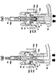
図1に、本発明の一実施形態にかかるポンプ式泡吐出容器の正面図を示す。
図1に示すように、本実施形態にかかるポンプ式泡吐出容器10は、発泡性液体が収容される容器本体12と、該容器本体12の上端の口部に着脱自在に装着されるノズル体14と、該ノズル体14と連通して容器本体12の内部へと延びた管体16とを備えている。ノズル体14の上方にはノズルヘッド部20が設けられており、該ノズルヘッド部20を上下動することによって、ノズル体14内部の気液混合部22内で形成された泡が、ノズルヘッド部20の下流側末端に設けられた吐出口24から吐出される。
Hereinafter, preferred embodiments of the present invention will be described with reference to the drawings.
In FIG. 1, the front view of the pump type foam discharge container concerning one Embodiment of this invention is shown.
As shown in FIG. 1, a pump-type
〈ポンプ式泡吐出容器の構成〉
本実施形態において、合成樹脂製の容器本体12は、発泡性を有する液体を収容するものであり、該容器本体12の口部12aの外周面には雄ネジが形成されている。一方、ノズル体14の下方に設けられたスカート状のベースキャップ部26の内周面には雌ねじが形成されており、容器本体の口部12aと螺合することで、ノズル体14が容器本体12に冠着して固定されている。ここで、本実施形態のノズル体14は、操作部及び吐出部となるノズルヘッド部20と、液用シリンダ28A及び空気用シリンダ28Bを構成する二重シリンダ28と、液用ピストン30と、空気用ピストン32とを、主な構成部品としているものである。
<Configuration of pump type foam discharge container>
In the present embodiment, the
以下、ノズル体14における各構成部品の具体的な構造について説明する。
図2に、本実施形態にかかるポンプ式泡吐出容器におけるノズル体の拡大断面図を示す。
二重シリンダ28は、一つの部品として射出成型法により合成樹脂で一体成形されたものである。すなわち、同心的に配置された大径の空気用シリンダ28Bと小径の液用シリンダ28Aとが一体的に成形されたものであり、また、空気用シリンダ28Bの上端開口縁部には、容器本体12の口部12a上端に載置される円環状のフランジ部28aが形成されている。
Hereinafter, a specific structure of each component in the
In FIG. 2, the expanded sectional view of the nozzle body in the pump type foam discharge container concerning this embodiment is shown.
The
二重シリンダ28の空気用シリンダ28Bは、フランジ部28aに続いて、容器本体12の口部12aの上端部の内径と同等あるいはわずかに小径の外径を有する短い大径部分と、それよりわずかに小径で均一な内径のシリンダ壁とからなる筒状の部分である。空気用シリンダ28Bのシリンダ壁の下端からは、さらに上方に反転して、連結部分28bが径方向内方に延びている。
The
二重シリンダ2の液用シリンダ28Aは、その上端が連結部分28bの径方向内端に連なって該連結部分28bから下方に延びているものであり、円筒形のシリンダ壁28cの下端に、後述する筒状係止体の下端の受け部となる円環状の台座部28dが形成され、その下方でボール弁34の弁座となる漏斗状の弁座部28eが形成され、さらにその下方に、容器本体12内から液用シリンダ28内部へと発泡性液体を導くための管体16を圧入するための円筒形の下側筒状部28fが形成されている。また、下側筒状部28fに圧入された管体16は、容器本体12内の底部付近まで延びている。
The
空気用ピストン32及び液用ピストン30は、それぞれが別個の部品として合成樹脂で射出成型法により成形され、その後で一つのピストン体として同心的に連結されているものである。二重シリンダ28に対して、空気用ピストン32の摺動シール部32aが空気用シリンダ28Bのシリンダ壁内面に沿って摺動するように設置され、また、液用ピストン30の摺動シール部30cが液用シリンダ28Aのシリンダ壁28c内面に沿って摺動するように設置されている。空気用ピストン32の上端にはノズルヘッド部20が連結されている。
Each of the
空気用ピストン32は、軸心部の上部小径部32bと、該上部小径部32bと同心的に配置された下部大径部32cとを、中間連結部32dを介して一体的に形成したものである。下部大径部32cの上端から径方向内側に中間連結部32dが形成され、中間連結部32dの内側周縁部から上部小径部32bが上方に立ち上がっている。下部大径部32cの下端には、空気用シリンダ28Bのシリンダ壁内面との間で充分に気密性を確保でき、且つ、該空気用シリンダ28Bの内面に対して上下方向に摺動できるように、摺動シール部32aが一体的に形成されている。
The
液用ピストン30は、全体が略円筒形状をしており、その軸心中空部は上部側の内径が下部側の内径よりも小さく形成されていて、上端部の内面側には、内径が上方に行く程大径となる漏斗状の弁座部30aが形成されている。弁座部30aの下方の外周面には、後述する弾性弁体38の内方弁部との接触面となる環状突部30bが所定の位置に形成されている。液用ピストン30の下端部には、液用シリンダ28Aのシリンダ壁28c内面を液密状態で上下動する摺動シール部30cが形成されていて、摺動シール部30cの内側には、後述するコイルスプリングの上端側の受け部となるように円環状の平面部が形成されている。
The
空気用ピストン32と液用ピストン30は、液用ピストン30の上端部分が空気用ピストン32の上部小径部32bの下部内側に圧入されることで、一つのピストン体として一体的に連結されている。このように一体化されたピストン体30及び32は、前記二重シリンダ28に対し、空気用ピストン32を空気用シリンダ28B内に挿入し、液用ピストン30を液用シリンダ28A内に挿入することによって、一体的に上下動が可能なように組み付けられている。
The
なお、液用ピストン30と液用シリンダ28Aとの間には、圧縮された状態のコイルスプリング(図2中、二点鎖線で示される)が介装されている。すなわち、液用シリンダ28Aの下端付近と液用ピストン30の下端付近との間に、後述する筒状係止体36の下端に形成された円環状の受け部36aを介して、コイルスプリングが介装されている。このため、ピストン体30及び32は、コイルスプリングのバネ力によって二重シリンダ28に対して常に上方に付勢されている。
A compressed coil spring (indicated by a two-dot chain line in FIG. 2) is interposed between the
また、以上の容器構成により、液用シリンダ28Aと液用ピストン30との内側の空間として液室Aが形成され、空気用シリンダ28Bと空気用ピストン32及び液用ピストン30とにより囲まれた空間として空気室Bが形成されている。また、液用ピストン30の上端部と空気用ピストン32の上部小径部32bの上端部内面との間に、混合器40が嵌入されており、該混合器40及び空気用ピストン32の上部小径部32bと、後述する多孔体ホルダ40とによって囲まれた、上下方向に延びた略円筒状の空間として気液混合室Cが形成されている。なお、液用ピストン30上方の外側と空気用ピストン32の上部小径部32bの内側の空間として、空気室Bから気液混合室Cへと空気を送り込むための空気通路Dが形成されている。
In addition, with the container configuration described above, the liquid chamber A is formed as an inner space between the
すなわち、空気用ピストン32の上部小径部32bは、その上端部近傍の内側に混合器40が嵌め込まれ、その内側が仕切られることによって気液混合室Cを形成しており、一方、該上部小径部32bの下部内側は、液用ピストン30の嵌入部となっている。液用ピストン30の上部外面の前記嵌入部に対応する箇所には、同一幅で同一深さの縦方向溝が円周方向で等間隔に複数本設けられており、これによって、液用ピストン30の上部外面と空気用ピストン32の内面との間に、円周方向で均等な間隔となるように、空気通路Dが形成されている。
That is, the upper small-
液用ピストン30の上部外面の嵌入部に対応する箇所には、前記縦方向溝を形成するための縦方向リブが設けられており、該縦方向リブは空気用ピストン32の上部小径部32bへと圧入可能なように、その外面を結ぶ仮想円の外径が空気用ピストン32の上部小径部32bの内径と略等しくされている。なお、空気通路Dを形成するための縦方向溝あるいは縦方向リブについては、液用ピストン30上部外面の嵌入部に対応する部分ではなく、空気用ピストン32の内面側に設けてもよい。
A longitudinal rib for forming the longitudinal groove is provided at a position corresponding to the fitting portion of the upper outer surface of the
また、液用ピストン上方の上部小径部32bの内側に圧入されている混合器40は、その上端側の外径が空気用ピストンの上部小径部32bの内径に略等しくなるように形成されていている。一方、混合器40の下端側の外径及び内径は、液用ピストン30の上端部と一致するように構成されている。
Further, the
空気導入口及び液体導入口
つづいて、図3に示す本実施形態にかかる混合器40の斜視図を参照し、本発明にかかるポンプ式泡吐出容器の特徴部分である空気導入口及び液体導入口の構造について詳しく説明する。
図3に示すように、本実施形態にかかる混合器40は、上下方向に厚みを有した略円盤状の部品であって、より厚みの大きい外円周部と厚みの小さい内円周部とによって、上下方向の断面は略H型の形状をなしている。
Following air inlet and the liquid inlet, with reference to the perspective view of the
As shown in FIG. 3, the
混合器40の外円周部には、上下方向の溝が円周方向に等間隔に8本ずつ設けられており、また、これに続く水平方向の溝が内部半径方向へと向けて円周方向に等間隔に8本ずつ設けられている。なお、この上下方向溝及び水平方向溝は、液用ピストン30上部外面と空気用ピストン32内面とによって形成される空間と連通しており、該空間とともに空気通路Dを形成している。このため、空気室B内の空気は、該8本の上下方向溝及び水平方向溝を介して、混合器40内部に形成される気液混合室Cへと送り込まれることになる。
さらに、混合器40の内円周部には、内円の円周方向に等間隔に上下方向の貫通孔が8つ設けられており、該貫通孔は、その下方において液室Aと連通している。これによって、液室A内の発泡性液体は、該8つの貫通孔内(液体通路)を介して、混合器40内部に形成される気液混合室Cへと送りこまれることになる。
Eight vertical grooves are provided at equal intervals in the circumferential direction on the outer circumferential portion of the
Further, the inner circumferential portion of the
ここで、空気室B内の空気は、混合器40中心部に近い側の前記水平方向溝の終端において混合器40内の空間へと導入されることから、図3に示すように、該終端が気液混合室Cへの空気導入口40aとなる。また、液室A内の発泡性液体は、前記貫通孔(液体通路)の上端において混合器40内の空間へと導入されることから、図3に示すように、該上端箇所が気液混合室Cへの液体導入口40bとなる。すなわち、本実施形態の混合器40においては、図3に示すように、空気導入口40aと、液体導入口40bとが、それぞれ8個ずつ個別に設けられていることになる。
Here, since the air in the air chamber B is introduced into the space in the
以上のように、本実施形態にかかるポンプ式泡吐出容器10においては、気液混合室Cへの空気導入口40aと液体導入口40bとが、複数ずつそれぞれ個別に設けられていることによって、該空気導入口40aを通過した空気と、該液体導入口40bを通過した発泡性液体とが、それぞれ線状の細流となって気液混合室C内へと導入されるため、両者が十分に大きな接触面積で混合され、良好な泡質の泡を形成することができる。また、発泡性液体と空気とが同一の導入口から気液混合室内へと流入する構成の場合、発泡性液体あるいは空気のいずれか一方のみが極端に多く流入してしまい、泡質が安定しないという問題があったものの、本実施形態のポンプ式泡吐出容器10においては、空気導入口40aと液体導入口40aとがそれぞれ個別に設けられており、該空気導入口40aを通過した空気と、該液体導入口40bを通過した発泡性液体とが、互いに異なる導入口を介して気液混合室C内へと導入されるため、発泡性液体と空気とが互いに競合することがなく、気液混合室C内への発泡性液体と空気との供給割合を安定化することができ、これによって、良好な泡質の泡を安定して吐出することができる。
As described above, in the pump-type
なお、空気導入口40a及び液導入口40bの個数については、いずれも2個以上であれば特に限定されないものの、いずれも4個以上であることが好ましく、さらにはいずれも8個以上であることが好ましい。空気導入口40a及び液導入口40bの個数が多いほど、気液混合室C内へと供給される空気及び発泡性液体を細流化することができるため、両者の接触面積が増大して、泡質が良好になる傾向にある。なお、本実施形態においては、空気導入口40a及び液導入口40bの個数を同一(8個ずつ)としているが、いずれも2個以上であれば両者の個数が異なっていてもよい。ただし、いずれか一方の導入口の個数が多すぎると、気液混合室内へと導入される発泡性液体あるいは空気の量が偏り、泡質が悪化してしまう恐れがあるため、両者の導入口の個数比が2:1〜1:2の範囲内であることが望ましい。
The number of
遮蔽部
図4に、本実施形態にかかるポンプ式泡吐出容器10における混合器40近傍の要部拡大断面図を示す。
図4に示すように、本実施形態の空気用ピストン32の上部には、混合器40が嵌入したその上方において、円筒内側方向へと張り出したドーナツ状の遮蔽部32eが設けられている。ここで、ドーナツ状の遮蔽部32eは、少なくとも液導入口40bの上方延長方向を遮るように内側方向へと張り出しており、また、その中央には孔32fが設けられている。本実施形態にかかるポンプ式泡吐出容器10においては、該ドーナツ状遮蔽部32eが設けられていることによって、液導入口40bからの発泡性液体の流入方向の直線上延長方向が遮られており、発泡性液体の流入方向は、気液混合室C内において該ドーナツ状遮蔽部32eと衝突することで、上方向から水平方向へと変向される。このため、空気導入口40a及び液導入口40bから導入した空気及び発泡性液体は、混合器40と該遮蔽部32eとにより形成された空間(気液混合室Cの一部)において、一旦、中心方向へと向かって流入方向を揃えるように整流された後、該遮蔽部32eの孔32f付近で他方向から流入した発泡性液体又は空気と衝突して上方へと向きを変え、該孔32fを介して、より下流側の気液混合室C及び泡吐出通路Eへと送り込まれる。ここで、混合器40内へと導入された空気及び発泡性液体は、遮蔽部32eの孔32f付近において他方向から流入した発泡性液体又は空気と激しく衝突するため、両者は均一且つ十分に混合され、良好な泡質の泡が形成される。
The shield portion 4, showing the enlarged sectional view of the
As shown in FIG. 4, a donut-shaped
すなわち、従来のポンプ式泡吐出容器においては、例えば、特許文献1〜3に記載の容器のように、通常、気液混合室下方の液導入口から導入された発泡性液体がそのまま向きを変えることなく上方の下流側へと送り込まれる構成であったため、発泡性液体は上方への層状の流れとなって優先的にノズル上方へと送り込まれ、発泡性液体と空気との接触面積が限られてしまい、両者を十分に混合できないという問題があった。これに対し、本実施形態にかかるポンプ式泡吐出容器10においては、図4に示すように、ドーナツ状遮蔽部32eが液導入口40bの上方延長方向を遮るように内側方向へと張り出しているため、混合器40の底部に設けられた液導入口40bから流入した発泡性液体は、上方へ移動した後、遮蔽部32eの下端に衝突して水平方向へと向きを変え、さらに孔32f付近で他方向から流入した空気あるいは発泡性液体と衝突して再度上方へと向きを変え、該孔32fを通じて上方へと送り込まれる。一方で、混合器40の側方に設けられた空気導入口40aから流入した空気は、水平方向に移動した後、孔32f付近で他方向から流入した空気あるいは発泡性液体と衝突して上方へと向きを変え、該孔32fを通じて上方へと送り込まれる。この結果、複数設けられた空気導入口40a及び液導入口40bによって細流化されて気液混合室C内へと導入された空気及び発泡性液体は、混合器40と該遮蔽部32eとにより形成された空間(気液混合室Cの一部)内で大きな接触面積をもって接触するとともに、孔32f付近で他方向から流入した空気又は発泡性液体と激しく衝突することによって十分に混合されるため、良好な泡質の泡を形成することができる。
That is, in the conventional pump-type foam discharge container, for example, like the containers described in Patent Documents 1 to 3, normally, the foamable liquid introduced from the liquid introduction port below the gas-liquid mixing chamber changes its direction as it is. The foaming liquid is preferentially sent to the upper part of the nozzle as a laminar flow upward, and the contact area between the foaming liquid and air is limited. As a result, there was a problem that the two could not be mixed sufficiently. On the other hand, in the pump-type
また、特許文献3に記載の容器においては、複数の気液合流部において合流した発泡性液体及び空気が、複数の泡連通孔を介して下流側の泡合流部へと供給される構成であるため、容器構成の歪みや付着した発泡性液体の乾燥等の理由によって、一部の液導入路あるいは空気導入路が閉塞してしまったり流路が狭くなってしまった場合、当該導入路の近傍の泡連通孔からは発泡性液体あるいは空気のみが優先的にノズル上方へと送り込まれることとなり、泡質が著しく悪化してしまう場合があった。これに対して、本実施形態10にかかるポンプ式吐出容器10においては、図4に示すように、液導入口40bから流入した発泡性液体と空気導入口40aから流入した空気が、混合器40と遮蔽部32eとにより形成された空間内において十分に混合された後、単一の孔32fを介して上方へと送り込まれる構成となっているため、例えば、一部の空気導入路あるいは液導入路が閉塞してしまったり流路が狭くなってしまった場合であっても、発泡性液体あるいは空気のいずれか一方のみが優先的にノズル上方へと送り込まれるようなことはなく、均質な泡を安定して供給することができる。
Moreover, in the container of patent document 3, it is the structure by which the foamable liquid and air which merged in several gas-liquid joining parts are supplied to a downstream foam joining part via several foam communicating holes. Therefore, if some of the liquid introduction path or air introduction path is blocked or the flow path becomes narrow due to distortion of the container configuration or drying of the attached foamable liquid, the vicinity of the introduction path From the bubble communication hole, only the foamable liquid or air is preferentially sent to the upper part of the nozzle, and the foam quality may be remarkably deteriorated. In contrast, in the pump-
空気導入口及び液体導入口の形成位置
また、図3及び4に示すように、本実施形態の空気導入口40aは混合器40の側方に設けられており、液導入口40bは混合器40の底部に設けられている。そして、図3に示したように、本実施形態の混合器40において、空気導入口40aと液導入口40bの位置は、水平方向断面円の半径方向(あるいは放射方向)において、互いに重ならないように配置されている。ここで、混合器40の側方に周方向に等間隔に設けられた空気導入口40aから導入された空気は、混合器40の中心部へと向かって、すなわち、混合器40の水平方向断面の半径方向へと流入する。一方で、液導入口40bは、空気導入口40aと半径方向において互いに重ならないように配置されているため、液導入口40aから流入する発泡性液体の流れと、空気導入口40aから流入する空気の流れとが、混合器40の導入部付近において競合せず、発泡性液体と空気とが流速を落とさずに混合器40内部へと流入することができる。このため、本実施形態にかかる泡吐出容器10においては、ノズルヘッド部の押し下げに要する圧力が小さくて済み、また、発泡性液体あるいは空気のいずれか一方が極端に多く流入してしまうこともないため、両者が均一に混合されて、良好な泡質の泡を形成することができる。
Positions for forming the air inlet and the liquid inlet As shown in FIGS. 3 and 4, the
なお、空気導入口40a及び液導入口40bの断面積については、特に限定されないものの、例えば、空気導入口の合計断面積としては6〜40mm2、液導入口の合計断面積としては0.3〜20mm2程度であることが望ましい。また、それぞれの断面積の比は、液導入口断面積/空気導入口断面積=2〜20であることが好ましい。下限値よりも小さいと空気の量が多くなりすぎ、上限値よりも大きいと空気の量が少なくなりすぎ、いずれの場合も良好な泡質が得られない場合がある。なお、本実施形態において、空気導入口40aの断面積は、0.25mm2(導入口1つ当たり)×8=2.0mm2であり、液導入口40bの断面積は、0.9mm2(導入口1つ当たり)×8=7.2mm2である。また、各導入口の断面積比は、液導入口断面積/空気導入口断面積=3.6である。
In addition, although it does not specifically limit about the cross-sectional area of the
混合器の変形例
なお、本発明のポンプ式泡吐出容器における混合器の構成は、空気導入口40aと液体導入口40bとがそれぞれ複数ずつ個別に設けられているものであればよく、上記実施形態に限られるものではない。図6,7に、本実施形態にかかる混合器の変形例140,240を示す。
図6に示す混合器140には、先述した混合器40と同様に、空気導入口140a及び液導入口140bが、それぞれ8個ずつ個別に設けられている。ここで、混合器140においては、空気導入路を形成する上面の水平方向溝が、いずれも外側から半径方向内側へ向かって狭くなるように形成されている。これによって、気液混合室C内へと導入される空気がより細流化され、且つ流入速度が速くなるため、発泡性液体との混合効率が向上し、より良質の泡を形成することができる。
また、図7に示す混合器240においては、液導入口240bの個数は8個であるものの、空気導入口240aが16個設けられている。そして、これによって、気液混合室C内へと導入される空気がより細流化され、発泡性液体との混合効率が向上し、より良質の泡を形成することができる。
Modification of the Mixer The configuration of the mixer in the pump-type foam discharge container of the present invention is not limited as long as a plurality of
In the
In the
以下、本実施形態のポンプ式泡吐出容器10における他の構成についての説明を続ける。
空気用ピストン32の上部小径部32bに連結されるノズルヘッド部20は、側壁部が内筒部20aと外筒部20bの二重壁に形成されており、内筒部20a内を通って上方で屈曲するL字形の貫通孔として、泡通路Eが形成されている。空気用ピストン32及び液用ピストン30を組み付けた二重シリンダ28にベースキャップ部26を冠着した後、ノズルヘッド部20の内筒部20aの下端部に空気用ピストン32の上部小径部32bの上端を嵌め込んで固着することで、ノズルヘッド部20と空気用ピストン32及び液用ピストン30は一体的に連結され、空気用ピストン32の上部小径部32bの上部内側に形成された気液混合室Cと、ノズルヘッド部20内部の泡通路Eとが連通される。
Hereinafter, the description about the other structure in the pump type
As for the
ノズルヘッド部20内の泡通路Eには、空気用ピストン32との連結に先立って、シート状の多孔体42a,42bを両端に張設した多孔体ホルダ42が、気液混合室Cの下流側に挿着されている。多孔体ホルダ42は、例えば、合成樹脂製の糸を編んだ網体をシート状の多孔体42a,42bとして、筒状の合成樹脂製スペーサ42cの両端に溶着して取付けたものでよい。また、上流側(気液混合室Cに近い側)の多孔体42aの網目よりも下流側(泡吐出口24に近い側)の多孔体42bの網目の方が細かくなるように形成されていることが、泡質の点から望ましい。
Prior to the connection with the
ノズル体14を容器本体12の口部12aと挟持して固定するためのベースキャップ部26については、中央部を開口した頂壁部26aと、頂壁部26aの外周縁部から垂下したスカート部26bと、頂壁部26aの開口縁部から直立した直立壁26cとからなり、頂壁部26aの下面には、空気用シリンダ28Bのフランジ部28aの内面と接触する環状筒部と、それよりも小径の環状筒部がそれぞれ垂下形成されている。
ベースキャップ26のスカート部26bは、内周面が雌ネジ部となっており、容器本体12の口部12aの外周面に形成された雄ネジ部に螺合されることで、ベースキャップ26は容器本体12の口部12aに冠着される。
As for the
The inner peripheral surface of the
また、液用ピストン30及び空気用ピストン32に対して、上方から固着するノズルヘッド部20は、その外筒部20bが、空気が通過できる隙間を有し、ベースキャップ部26の直立壁26cの先端部により案内される。
さらに、ベースキャップ26の直立壁26cの内周縁とノズルヘッド部20の外筒部20bとの外周面との間隙を介して、容器本体12内のヘッドスペース(発泡性液体の液面よりも上方の空間部)へと外部の空気を導入するため、空気用シリンダ28Bのシリンダ壁上部に空気孔28gが開設されており、空気用ピストン32の摺動シール部32cは、空気用ピストン32が上限位置にある状態で、空気孔28gを内側から覆って閉鎖するように、断面が浅いコの字形状となるように形成されている。そして、空気用ピストン32が下方へ移動すると空気孔28gが摺動シール部32cから開放され、外気と容器本体12内とが連通する。
Further, the
Furthermore, the head space in the container body 12 (above the liquid level of the foamable liquid) is interposed via a gap between the inner peripheral edge of the
液用シリンダ28Aの下端付近の漏斗状の弁座部28e上にはボール弁34が載置されており、該弁座部28eとボール弁34とによって、液室Aの負圧時には液室Aの下端入口を開口する第1逆止弁が構成されている。また、液用ピストン30と液用シリンダ28Aの内側には、合成樹脂製の棒状弁体44が設置されており、液用シリンダ28Aの下方には、棒状弁体44の上昇を制限する合成樹脂製の筒状係止体36が設置されている。そして、棒状弁体44の上端付近と液用ピストン30の上端付近とによって、液室Aの加圧時に液室Aの上端出口を開口する第2逆止弁が構成されている。
A
すなわち、液用ピストン30と液用シリンダ28Aの内側に設置されている棒状弁体44は、その上方が大径で下方が小径に形成されているとともに、液用ピストン30の上端付近の内周面に形成されているすり鉢状の弁座部30aに対して、棒状弁体44の上端付近の外周面には、さらに大径で逆円錐状の弁体部44aが、少なくともその最大外径部が液用ピストン30の弁座部30aの最小内径部よりも大径となるように形成されており、この棒状弁体44の弁体部44aと液用ピストン30の弁座部30aとによって第2逆止弁が構成されている。
That is, the rod-shaped
棒状弁体44の小径の下端部には、その上部に対して段差を形成するような径大部44bが下端を先細りとした状態で形成されており、この径大部44bが筒状係止体36によって所定の範囲のみ上下動可能なように保持されている。これによって、棒状弁体44は、液用シリンダ28Aに対して所定の範囲のみ上下動可能なように保持されており、棒状弁体42によって、液用ピストン30及び空気用ピストン32の上限位置が規制されている。
At the lower end portion of the small diameter of the rod-shaped
すなわち、筒状係止体36は、液用シリンダ28A下方の台座部28eに支えられた状態で立設されており、その下端部には円環状の受け部36aが形成されている。また、円環状受け部36aの上方は液通路となる縦方向の開口溝(又は割溝)を放射状に複数本設けた開口筒部36bが形成され、さらにその上方は完全な(無孔の)円筒部36cが形成されている。そして、無孔円筒部36cの上端には、続いて内向環状突起36dが形成されている。なお、下端の円環状受け部36aはコイルスプリングの下端側の受け部となっている。
That is, the cylindrical locking body 36 is erected in a state of being supported by the
筒状係止体36の上端に形成された内向環状突起36dによって棒状弁体44の下端の径大部44bを係止し、棒状弁体44の上昇を阻止することで、棒状弁体44の弁体部44aが液用ピストン30の弁座部30aに当接することと共働して、コイルスプリングにより上方に付勢されている液用ピストン30及び空気用ピストン32の上限位置が規制されている。なお、この筒状係止体36の下端部によって、第1逆止弁のボール弁34の上昇距離が規制されている。
The large-
さらに、空気用ピストン32の中間連結部32dに開設された吸気孔32gと、空気用ピストン32及び液用ピストン30の圧入連結部分に形成された空気通路Dの入口側(空気室B側)とに対し、空気室Bの負圧時にのみ吸気孔32gから空気室B内へと空気を吸入し、且つ空気室Bの加圧時にのみ空気室Bと空気通路Dを連通させるように作動する第3逆止弁が設けられている。
Further, an
第3逆止弁は、空気用ピストン32の中間連結部32dの外周側下面と、液用ピストン30の外周面に形成された環状突部30b上面と空気用ピストン32の中間連結部32dとの間に取り付けられた軟質合成樹脂製の弾性弁体38とによって構成されている。弾性弁体36は、短い円筒状の筒状基部38aに対し、該筒状基部38aの下端部近傍から外方に延びる薄肉で円環状の外方弁部38bと、該筒状基部38aの下端部近傍から内方に延びる薄肉で円環状の内方弁部38cとを一体的に形成したものである。
The third check valve includes an outer peripheral side lower surface of the
弾性弁体36は、空気用ピストン32の中間連結部32dにより筒状基部38aが固定されている状態であり、外方弁部38bの上面側外縁部が、吸気孔32gよりも径方向外側で中間連結部32dの下面(空気室B側)に接触すると共に、内方弁部38cの下面側内縁部が、液用ピストン30に形成された環状突部30bの上面と接触するように、空気室Bの上部に設置されている。弾性弁体38の内方弁部38cは、その上方の中間連結部32dの下面に対して、上方へ変位するのに十分な間隔を有している。
The elastic valve body 36 is in a state in which the cylindrical base portion 38a is fixed by the intermediate connecting
以上のように、弾性弁体38が設置された第3逆止弁においては、通常、外方弁部38bの外縁部が中間連結部32dの下面に接触して、空気室Bと外気の連通路である吸気孔32gを閉鎖し、また、内方弁部38cの内縁部が液用ピストン30の環状突部30bに接触して、空気室Bから空気通路Dへの入口部分を閉鎖し、空気用ピストン32が下降して空気室Bが加圧されると、弾性弁体38の内方弁部38cが上方に変位(弾性変形)して環状突部30bから離れることにより、空気通路Dの入口を開口し、また、逆に空気用ピストン32が上昇して空気室Bが負圧になると、弾性弁体38の外方弁部38bが下方に変位(弾性変形)して中間連結部32dの下面から離れることにより、吸気孔32gを開口する。
As described above, in the third check valve in which the
〈ポンプ式泡吐出容器の作動状態〉
本発明の一実施形態にかかるポンプ式泡吐出容器10は、概略以上のように構成されている。つづいて、本実施形態のポンプ式泡吐出容器10の作動状態について以下に説明する。図5に、本実施形態にかかるポンプ式泡吐出容器10のノズルヘッド部の下降時及び上昇時における作動状態の説明図を示す((A):下降時,(B)上昇時)。
本実施形態のポンプ式泡吐出容器10においては、その組み立て完成時から容器本体12内に液体が充填されており、消費者が使用を開始する直前まで、図1に示すように、空気用ピストン32及び液用ピストン30がコイルスプリングの付勢力によって上限位置まで上昇している状態となっている。また、容器本体12内のヘッドスペースへの外気導入手段として空気用シリンダ28Bのシリンダ壁の上部に開設された空気孔28gは、空気用ピストン32の摺動シール部32aによって閉じられている。また、第1逆止弁においては、ボール弁34が弁座部28eに密着して、液室Aの下端入口が閉鎖されており、第2逆止弁においては、棒状弁体44の弁体部44aが擂鉢状の弁座部30aと密着して、液室Aの上端出口が閉鎖されている。また、第3逆止弁では、弾性弁体38の外方弁部38bが吸気孔32gよりも外周側の中間連結部32dの下面に接触して、吸気孔32gが閉鎖されているとともに、弾性弁体38の内方弁部38cが液用ピストン30の環状突部30bの上面に接触して、空気通路Dの入口が閉鎖されている。
<Operating state of pump type foam discharge container>
The pump type
In the pump-type
このような状態から、消費者が使用を開始して、ノズルヘッド部20を押し下げると、図5(A)に示すように、空気用ピストン32と液用ピストン30とが、ピストン体として一体的に下降する。これに対して、棒状弁体44は混合器40の下端面と当接するまでは下降しない。したがって、第2逆止弁においては、ノズルヘッド部20とともに空気用ピストン32と液用ピストン30が下降し始めると、棒状弁体44の弁体部44aと液用ピストン30の弁座30aとが離れて、液室Aの上端出口が開口される。このとき、下方の第1逆止弁においては、ボール弁34が弁座部28eに密着したままで液室Aの下端が閉鎖されている。また、第3逆止弁においては、空気用ピストン32の下降により加圧された空気室Bの空気圧によって、弾性弁体38が中間連結部32d側への押圧力を受けている。このため、中間連結部32dに筒状基部38aが固定された弾性弁体38は、その外方弁部38bが中間連結部32dの下面にさらに強く押しつけられ、また、内方弁部38cが上方へと撓んで液用ピストン30の環状突部30bの上面から離れるため、吸気孔32gは閉鎖状態を維持し、空気通路Dの入口が開口される。
In this state, when the consumer starts use and pushes down the
このため、消費者が使用を開始して、最初にノズルヘッド部20を押し下げた際には、図5(A)中矢印で示すように、空気室Bから気液混合室Cへと空気が送り込まれるとともに、液室Aからは空気のみが気液混合室Cへと送り込まれることから、ノズルヘッド部40内の泡通路Gからは空気のみが吐出されることとなる。このような最初のノズルヘッド部20の押し下げを解除すると、コイルスプリングの付勢力によって液用ピストン30が再上昇し、これと一体的に空気用ピストン32も直ちに再上昇する。これにわずかに遅れて、上昇した液用ピストン30の弁座部30aが棒状弁体44の弁体部44aへと当接して上方への力を付与するために、棒状弁体44も上昇を開始して、最終的に、液用ピストン30及び空気用ピストン32は、図1に示すように上限位置にまで戻る。
For this reason, when the consumer starts using the
このようにノズルヘッド部20の押し下げを解除することで、図5(B)に示すように、空気用ピストン32と液用ピストン32が一体的に上昇することによって、空気室Bが負圧状態となるとともに、第2逆止弁においては、棒状弁体44の弁体部44aと液用ピストン30の弁座部30aとが密着して、液室Aの上端出口が閉鎖され、さらに液用ピストン30と一体的に棒状弁体44も上昇することから、液室Aも負圧状態となる。そして、液室Aが負圧状態になることによって、第1逆止弁では、ボール弁34が弁座部28eから離れて液室Aの下端入口が開口され、また、第3逆止弁の弾性弁体38においては、その外方弁部38bが下方へと撓んで中間連結部32dの下面から離れ、その内方弁部38cが下方へと復帰して液用ピストン30の環状突部30bの上面へと接触するため、吸気孔32gが開口されて、空気通路Dの入口は閉鎖される。
By releasing the depression of the
この結果、図5(B)中矢印で示すように、液室Aには、管体16を介して容器本体12内の発泡性液体が吸い上げられるとともにに、ノズルヘッド部20の内筒部20aの外周面とベースキャップ26の直立壁26cの内周面との隙間から進入した外部の空気が、吸気孔32gを通過して空気室Bへと吸入されて、泡出しの準備状態が完了される。なお、容器本体12内から液室Aへと発泡性液体が吸い上げられることで、その分だけ容器本体のヘッドスペースの容積が増加するため、このままではヘッドスペースが負圧状態となるが、ノズルヘッド部20の押し下げが解除されて上昇している間は、空気孔28gが開口したままであり、ノズルヘッド部20の内筒部20aの外周面とベースキャップ26の直立壁26cの内周面との隙間から進入した外部の空気が、外気導入手段としての空気孔28gから直ちに容器本体12内へ吸い込まれるため、このような容器本体12内のヘッドスペースの負圧状態は直ちに解消される。
As a result, as indicated by an arrow in FIG. 5B, the foamable liquid in the
以上のように、液室Aに発泡性液体が満たされて、且つノズルヘッド部20が上限位置まで戻った状態で、再びノズルヘッド部20を押し下げると、空気用ピストン32、液用ピストン30及び第1〜第3の各逆止弁は、上記の押し下げ操作時と同様に作動する。この結果、空気用ピストン32及び液用ピストン30の下降に伴って、空気室Bと液室Aが加圧されることによって、混合器40に設けられた複数個の空気導入口40aを通って、空気室Bからの空気が気液混合室Cへと圧送されるとともに、液室Aからの発泡性液体が液導入口40bを通って気液混合室Cに液体が送り込まれて、両者は気液混合室Cで混合して泡が形成される。
As described above, when the
ここで、本実施形態にかかる泡吐出容器10においては、気液混合室Cへの空気導入口40aと液体導入口40bとが、複数ずつそれぞれ個別に設けられていることによって、空気室Bからの空気と液室Aからの発泡性液体とが、それぞれ線状の細流となって気液混合室C内へと導入されるため、両者が十分に大きな接触面積で混合され、良好な泡質の泡を形成することができる。また、空気導入口40aと液体導入口40bとがそれぞれ個別に設けられているため、気液混合室C内への発泡性液体と空気との供給割合を安定化することができ、これによって、良好な泡質の泡を安定して吐出することができる。
Here, in the
また、本実施形態にかかる泡吐出容器10においては、空気用ピストン32の上部において、液導入口40bの上方延長方向を遮るように内側方向へと張り出したドーナツ状遮蔽部32eが設けられており、その中央部には単一の孔32fが設けられている。そして、このドーナツ状遮蔽部32eが設けられることによって、気液混合室C内へと導入される空気及び発泡性液体は、気液混合室Cの中心方向へと向かって流入方向を揃えるように整流され、中心部付近で他方向から流入した発泡性液体又は空気と激しく衝突し、孔32fを介して下流側へと送り込まれるため、両者が均一且つ十分に混合され、良好な泡質の泡が形成される。
In addition, in the
さらに、本実施形態にかかる泡吐出容器10においては、混合器40における空気導入口40aと液導入口40bの位置が、混合器40の水平方向断面の半径方向において、互いに重ならないように配置されているため、液導入口40bから流入する発泡性液体の流れと、空気導入口40aから流入する空気の流れとが、混合器40の導入部付近において競合せず、また、発泡性液体と空気とが流速を落とさずに混合器40内部へと流入することができる。このために、ノズルヘッド部の押し下げに要する圧力が小さくて済み、また、発泡性液体あるいは空気のいずれか一方が極端に多く流入してしまうことがないため、両者が均一に混合されて、良好な泡質の泡を形成することができる。
Furthermore, in the
なお、以上のようにして気液混合室C内において形成された泡は、つづいてノズルヘッド部20内の泡通路Eにおいて配設されたシール状の多孔体42a,42bを、目の粗い方(42a)から目の細かい方(42b)へと順に通過して、さらに細かく均質な泡に再形成され、最終的にノズルヘッド部20の先端に設けられた吐出部24から吐出される。
Note that the bubbles formed in the gas-liquid mixing chamber C as described above can be applied to the seal-like
つづいて、ノズルヘッド部20の押し下げ操作を解除すると、空気用ピストン32、液用ピストン30及び第1〜第3の各逆止弁は、上記の押し下げ操作の解除時と同様に作動する。この結果、液室Aには、再び容器本体12内の発泡性液体が管体16を介して吸い込まれるとともに、空気室Bには、容器外部の空気が吸気孔32gから吸い込まれ、泡出しの準備状態となる。そして、これ以後、ノズルヘッド部20の押し下げ操作とその解除を繰り返すことによって、ノズルヘッド部20の先端に設けられた吐出部24から所望の量の泡を吐出させることができる。
Subsequently, when the push-down operation of the
以上、本発明のポンプ式泡吐出容器の一実施形態について説明したが、本発明は、上記実施形態に示した具体的な構造のみに限定されるものではなく、発泡性液体と空気とを気液混合室内において混合して泡を形成するポンプ式泡吐出容器であれば、そのポンプ機構についても、上記実施形態に示した機構に限定されず、他の従来公知のポンプ機構によって実施することも可能であり、また、他の構成部分については具体的な用途等に応じて適宜設計変更することが可能である。 As mentioned above, although one embodiment of the pump-type foam discharge container of the present invention has been described, the present invention is not limited to the specific structure shown in the above-described embodiment, and the foamable liquid and the air are evacuated. If it is a pump type foam discharge container which mixes in a liquid mixing chamber and forms foam, the pump mechanism is not limited to the mechanism shown in the above-mentioned embodiment, and can be carried out by other conventionally known pump mechanisms. The other components can be appropriately changed in design according to the specific application.
10 ポンプ式泡吐出容器
12 容器本体
14 ノズル体
16 管体
20 ノズルヘッド部
22 気液混合部
24 吐出口
26 ベースキャップ部
28 二重シリンダ(28A:液用シリンダ,28B:空気用シリンダ)
30 液用ピストン
32 空気用ピストン
34 ボール弁
36 筒状係止体
38 弾性弁体
40 混合器
42 多孔体ホルダ
44 棒状弁体
DESCRIPTION OF
30 Piston for liquid 32 Piston for
Claims (3)
前記ノズル体は、
前記容器本体内と連通する液用シリンダ部と、
前記液用シリンダ部と摺接して上下動が可能であり、該液用シリンダ部との間隙を液室として構成するとともに、その上方向への移動によって容器本体内の発泡性液体を該液室内へと吸入し、且つその下方向への移動によって該液室内の発泡性液体を気液混合部へと圧送する液用ピストン部と、
前記液室と連通し、気液混合部へと発泡性液体を導入する液用導入路と、
空気用シリンダ部と、
前記空気用シリンダ部と摺接して上下動が可能であり、該空気用シリンダ部との間隙を空気室として構成するとともに、その上方向への移動によって容器外部の空気を該空気室内へと吸入し、且つその下方向への移動によって該空気室内の空気を気液混合部へと圧送する空気用ピストン部と、
前記空気室と連通し、気液混合部へと空気を導入する空気用導入路と、
前記液用導入路及び前記空気用導入路と連通し、前記液室内から導入された発泡性液体と前記空気室内から導入された空気とを混合して泡を形成する気液混合部と、
前記気液混合部の下流側と連通しており、且つ前記液用ピストン及び前記空気用ピストンと連動して上下動が可能であって、その下方向への移動によって前記気液混合部内で形成された泡を、その下流側末端に設けられた泡吐出口から吐出するノズルヘッド部と
を備え、
前記気液混合部において、
前記液用導入路と該気液混合部内とを連通する二以上の液導入口と、
前記空気用導入路と該気液混合部内とを連通する二以上の空気導入口と
がそれぞれ個別に設けられており、且つ
前記二以上の液導入口からの発泡性液体流入方向の直線上延長方向を遮って該発泡性液体流入方向を変向するとともに、前記二以上の液導入口から流入した発泡性液体及び前記二以上の空気導入口から流入した空気を単一の孔を介して下流側へと送出する遮蔽部が設けられている
ことを特徴とするポンプ式泡吐出容器。 An effervescent liquid contained in the container body by moving up and down a nozzle head part provided above the container body and a nozzle body attached to the mouth of the container body In a pump-type foam discharge container that mixes air and air in a gas-liquid mixing part to form foam, and discharges the foam from a foam discharge port provided in the nozzle head part,
The nozzle body is
A liquid cylinder portion communicating with the inside of the container body;
The liquid cylinder portion can be moved up and down while being in sliding contact with the liquid cylinder portion, and a gap between the liquid cylinder portion is configured as a liquid chamber, and the foamable liquid in the container body is moved upward by moving the liquid cylinder portion. A liquid piston section that sucks the liquid into the liquid chamber and pumps the foamable liquid in the liquid chamber to the gas-liquid mixing section by moving downwardly;
A liquid introduction path that communicates with the liquid chamber and introduces a foamable liquid into the gas-liquid mixing section;
An air cylinder,
The air cylinder part can be moved up and down in sliding contact with the air cylinder part, and the air chamber is configured as an air chamber, and the air outside the container is sucked into the air chamber by the upward movement thereof. And an air piston portion that pumps the air in the air chamber to the gas-liquid mixing portion by the downward movement thereof,
An air introduction path that communicates with the air chamber and introduces air into the gas-liquid mixing section;
A gas-liquid mixing unit that communicates with the liquid introduction path and the air introduction path, and forms foam by mixing the foamable liquid introduced from the liquid chamber and the air introduced from the air chamber;
It communicates with the downstream side of the gas-liquid mixing unit and can move up and down in conjunction with the liquid piston and the air piston, and is formed in the gas-liquid mixing unit by moving downwardly. And a nozzle head part that discharges the foam from a foam outlet provided at the downstream end thereof,
In the gas-liquid mixing part,
Two or more liquid inlets communicating the liquid introduction path and the gas-liquid mixing section;
Two or more air inlets communicating with the air introduction path and the gas-liquid mixing part are individually provided, and the linear extension of the foaming liquid inflow direction from the two or more liquid inlets The foaming liquid inflow direction is changed by blocking the direction, and the foaming liquid flowing in from the two or more liquid inlets and the air flowing in from the two or more air inlets are downstream through a single hole. A pump-type foam discharge container, characterized in that a shielding portion is provided for delivery to the side.
該気液混合部の底部に前記液導入口が設けられ、
該気液混合部の側方に前記空気導入口が設けられ、
該液導入口及び空気導入口の上方において、略円筒状空間の内側方向へと張り出し、中央部に単一の孔を有したドーナツ状の遮蔽部が設けられ、且つ
前記発泡性液体が該液導入口を介して上方へ向かって気液混合部内へと流入し、
該遮蔽部が、少なくとも該液導入口の上方延長方向を遮るように、略円筒状空間の内側方向へと張り出している
ことを特徴とする請求項1記載のポンプ式泡吐出容器。 The gas-liquid mixing part has a substantially cylindrical space extending in the vertical direction,
The liquid inlet is provided at the bottom of the gas-liquid mixing section;
The air inlet is provided on the side of the gas-liquid mixing section,
Above the liquid introduction port and the air introduction port, a donut-shaped shielding part is provided that projects inward in a substantially cylindrical space and has a single hole in the center, and the foamable liquid is the liquid. It flows into the gas-liquid mixing part upward through the inlet,
2. The pump-type foam discharge container according to claim 1, wherein the shielding part projects inward in the substantially cylindrical space so as to shield at least the upward extension direction of the liquid introduction port.
該気液混合部の底部に前記液導入口が設けられ、
該気液混合部の側方に前記空気導入口が設けられ、且つ
該気液混合部の水平方向断面円上における該液導入口及び該空気導入口の位置が、該水平方向断面円の半径方向において互いに重ならないように配置されている
ことを特徴とする請求項1又は2記載のポンプ式泡吐出容器。 The gas-liquid mixing part has a substantially cylindrical space extending in the vertical direction,
The liquid inlet is provided at the bottom of the gas-liquid mixing section;
The air inlet is provided on the side of the gas-liquid mixing unit, and the position of the liquid inlet and the air inlet on the horizontal cross-sectional circle of the gas-liquid mixing unit is the radius of the horizontal cross-sectional circle. The pump type foam discharge container according to claim 1 or 2, wherein the pump type foam discharge container is arranged so as not to overlap each other in the direction.
Priority Applications (1)
| Application Number | Priority Date | Filing Date | Title |
|---|---|---|---|
| JP2010259438A JP5603753B2 (en) | 2010-11-19 | 2010-11-19 | Pump type foam discharge container |
Applications Claiming Priority (1)
| Application Number | Priority Date | Filing Date | Title |
|---|---|---|---|
| JP2010259438A JP5603753B2 (en) | 2010-11-19 | 2010-11-19 | Pump type foam discharge container |
Publications (2)
| Publication Number | Publication Date |
|---|---|
| JP2012110799A JP2012110799A (en) | 2012-06-14 |
| JP5603753B2 true JP5603753B2 (en) | 2014-10-08 |
Family
ID=46495608
Family Applications (1)
| Application Number | Title | Priority Date | Filing Date |
|---|---|---|---|
| JP2010259438A Active JP5603753B2 (en) | 2010-11-19 | 2010-11-19 | Pump type foam discharge container |
Country Status (1)
| Country | Link |
|---|---|
| JP (1) | JP5603753B2 (en) |
Cited By (2)
| Publication number | Priority date | Publication date | Assignee | Title |
|---|---|---|---|---|
| CN111479758A (en) * | 2017-12-15 | 2020-07-31 | 花王株式会社 | Foam discharger |
| US11247220B2 (en) | 2017-12-15 | 2022-02-15 | Kao Corporation | Foam discharger |
Families Citing this family (16)
| Publication number | Priority date | Publication date | Assignee | Title |
|---|---|---|---|---|
| JP5971759B2 (en) * | 2012-11-30 | 2016-08-17 | 株式会社吉野工業所 | Former pump |
| KR101785252B1 (en) * | 2013-07-17 | 2017-10-12 | 가부시키가이샤 요시노 고교쇼 | Foamer dispenser, and container with foamer dispenser |
| JP6138614B2 (en) * | 2013-07-17 | 2017-05-31 | 株式会社吉野工業所 | Former dispenser and container with former dispenser |
| JP6326319B2 (en) * | 2014-07-31 | 2018-05-16 | 株式会社吉野工業所 | Squeeze discharge container |
| JP6669692B2 (en) | 2016-06-30 | 2020-03-18 | 花王株式会社 | Foam discharge container |
| US11596957B2 (en) | 2017-11-17 | 2023-03-07 | Frieslandcampina Nederland B.V. | Apparatus and methods for dispensing and foaming of a product |
| JP7189738B2 (en) * | 2018-11-14 | 2022-12-14 | 花王株式会社 | foam dispenser |
| JP7189737B2 (en) * | 2018-11-14 | 2022-12-14 | 花王株式会社 | foam dispenser |
| JP7193999B2 (en) * | 2017-12-15 | 2022-12-21 | 花王株式会社 | foam dispenser |
| US10779690B2 (en) * | 2017-12-27 | 2020-09-22 | Kao Corporation | Foaming dispenser |
| JP7221031B2 (en) * | 2018-11-19 | 2023-02-13 | 花王株式会社 | foam dispenser |
| JP7149750B2 (en) * | 2018-07-18 | 2022-10-07 | 花王株式会社 | foam dispenser |
| US11351560B2 (en) | 2018-07-18 | 2022-06-07 | Kao Corporation | Foam discharger |
| JP7283986B2 (en) * | 2019-06-13 | 2023-05-30 | 花王株式会社 | foam dispenser |
| JP6808870B1 (en) * | 2020-03-31 | 2021-01-06 | 大和製罐株式会社 | Pump dispenser and discharge container |
| JP6808869B1 (en) * | 2020-03-31 | 2021-01-06 | 大和製罐株式会社 | Pump dispenser and discharge container |
Family Cites Families (7)
| Publication number | Priority date | Publication date | Assignee | Title |
|---|---|---|---|---|
| JPH0425240Y2 (en) * | 1985-12-26 | 1992-06-16 | ||
| JPH0715558U (en) * | 1993-08-23 | 1995-03-14 | 東洋製罐株式会社 | Foam jet pump |
| JP3215641B2 (en) * | 1996-12-26 | 2001-10-09 | 株式会社吉野工業所 | Foam squirt pump container |
| JP4716462B2 (en) * | 2000-09-13 | 2011-07-06 | 大和製罐株式会社 | Pump type foaming container |
| US6868990B2 (en) * | 2002-09-26 | 2005-03-22 | Emsar, Inc. | Fluid dispenser with shuttling mixing chamber |
| US20050115988A1 (en) * | 2003-12-01 | 2005-06-02 | Brian Law | Multiple liquid foamer |
| JP5556383B2 (en) * | 2010-05-31 | 2014-07-23 | 花王株式会社 | Foam discharge container |
-
2010
- 2010-11-19 JP JP2010259438A patent/JP5603753B2/en active Active
Cited By (3)
| Publication number | Priority date | Publication date | Assignee | Title |
|---|---|---|---|---|
| CN111479758A (en) * | 2017-12-15 | 2020-07-31 | 花王株式会社 | Foam discharger |
| US11247220B2 (en) | 2017-12-15 | 2022-02-15 | Kao Corporation | Foam discharger |
| TWI802619B (en) * | 2017-12-15 | 2023-05-21 | 日商花王股份有限公司 | foam dispenser |
Also Published As
| Publication number | Publication date |
|---|---|
| JP2012110799A (en) | 2012-06-14 |
Similar Documents
| Publication | Publication Date | Title |
|---|---|---|
| JP5603753B2 (en) | Pump type foam discharge container | |
| JP5873247B2 (en) | Pump type foam discharge container | |
| US8056767B2 (en) | Discharge container | |
| JP6226763B2 (en) | Pump type discharge container | |
| US9868128B2 (en) | Foam dispensing assembly | |
| JP6144209B2 (en) | Pump type discharge container | |
| JP4716462B2 (en) | Pump type foaming container | |
| JPH09193953A (en) | Foam ejecting pump container | |
| JP6389770B2 (en) | Nozzle member | |
| JP2022038446A (en) | Pump dispenser | |
| JP5178390B2 (en) | Pump type discharge container | |
| JP4931057B2 (en) | Foam ejection container | |
| JP4911505B2 (en) | Foam ejection container | |
| JP3238855B2 (en) | Container with foam ejection pump | |
| JPH09220502A (en) | Check valve structure for resin pump | |
| WO2023153503A1 (en) | Pump dispenser | |
| JP7076304B2 (en) | Foam ejector | |
| JP2011200766A (en) | Sprayer | |
| JP6910879B2 (en) | Discharger | |
| JP2019210001A (en) | Foam discharge device | |
| JP6116269B2 (en) | Foam dispenser | |
| JP2024000452A (en) | foam pump dispenser |
Legal Events
| Date | Code | Title | Description |
|---|---|---|---|
| A621 | Written request for application examination |
Free format text: JAPANESE INTERMEDIATE CODE: A621 Effective date: 20131010 |
|
| A977 | Report on retrieval |
Free format text: JAPANESE INTERMEDIATE CODE: A971007 Effective date: 20140725 |
|
| TRDD | Decision of grant or rejection written | ||
| A01 | Written decision to grant a patent or to grant a registration (utility model) |
Free format text: JAPANESE INTERMEDIATE CODE: A01 Effective date: 20140729 |
|
| A61 | First payment of annual fees (during grant procedure) |
Free format text: JAPANESE INTERMEDIATE CODE: A61 Effective date: 20140822 |
|
| R150 | Certificate of patent or registration of utility model |
Ref document number: 5603753 Country of ref document: JP Free format text: JAPANESE INTERMEDIATE CODE: R150 |