JP5602003B2 - Method of burying spiral material - Google Patents
Method of burying spiral material Download PDFInfo
- Publication number
- JP5602003B2 JP5602003B2 JP2010284467A JP2010284467A JP5602003B2 JP 5602003 B2 JP5602003 B2 JP 5602003B2 JP 2010284467 A JP2010284467 A JP 2010284467A JP 2010284467 A JP2010284467 A JP 2010284467A JP 5602003 B2 JP5602003 B2 JP 5602003B2
- Authority
- JP
- Japan
- Prior art keywords
- movable
- ground
- screw
- pushing
- spiral material
- Prior art date
- Legal status (The legal status is an assumption and is not a legal conclusion. Google has not performed a legal analysis and makes no representation as to the accuracy of the status listed.)
- Expired - Fee Related
Links
Images


Landscapes
- Piles And Underground Anchors (AREA)
Description
この発明は、螺旋材の地盤埋設方法に係り、特に構築構造において螺旋材を地盤に回転しつつ押し込んで設置する螺旋材の地盤埋設方法に関する。 The present invention relates to a ground material embedding method for a spiral material, and more particularly to a ground material embedding method for a spiral material in which a spiral material is pushed into a ground while being installed in a construction structure.
道路、擁壁等の地盤の安定化を図るための構築構造において、壁面の壁面ブロックの背面では、螺旋材を地盤に押し込んで埋設しているものがある。 In the construction structure for stabilizing the ground such as roads and retaining walls, there is a structure in which a spiral material is pushed into the ground and embedded on the back surface of the wall surface block of the wall surface.
特許文献1に記載のアンカー打ち込み装置は、外周面にスクリュー(螺旋材)を有する筒状のアンカーを回転させながら地盤に押し込む回転押込装置を備えるとともに、この回転押込装置にセットされたアンカーの中からアンカーの下方を掘削する掘削装置を備えたものである。 The anchor driving device described in Patent Document 1 includes a rotary pushing device that pushes into a ground while rotating a cylindrical anchor having a screw (spiral material) on an outer peripheral surface, and includes an anchor set in the rotary pushing device. A drilling device for drilling the bottom of the anchor is provided.
ところが、従来、螺旋材を地盤に回転しつつ押し込む際に、その螺旋材の回転数と貫入量(押込量)とが適合せず、その作業が面倒になるとともに、その作業に用いる装置が複雑な構成であり、改善が望まれていた。 However, conventionally, when the helical material is pushed into the ground while rotating, the rotational speed of the helical material and the penetration amount (pushing amount) do not match, and the work becomes troublesome and the apparatus used for the work is complicated. Therefore, improvement was desired.
そこで、この発明の目的は、螺旋材の回転数と貫入量(押込量)とを適合させて、螺旋材を地盤に押し込む作業を容易にするとともに、その作業に用いる装置を簡単な構成にできる螺旋材の地盤埋設方法を提供することにある。 Accordingly, an object of the present invention is to adapt the rotational speed and penetration amount (pushing amount) of the spiral material to facilitate the work of pushing the spiral material into the ground, and to simplify the configuration of the apparatus used for the work. The object is to provide a method for burying a spiral material in the ground.
この発明は、
螺旋材を地盤に押し込んで設置する螺旋材の地盤埋設方法において、
設置台部が備えられた装置用架台と前記設置台部上で移動可能な可動式スリット板及び可動式螺旋材押込機とを備えた押込装置を設け、
前記螺旋材は、前端が前記地盤に押し込まれて行くスクリュー部と、前端が前記スクリュー部の後端に接続される接続ロッドとを備え、
前端が前記接続ロッドの後端に接続されるとともに後端が前記可動式螺旋材押込機に支持される押進補助用スクリュー部材を設け、
前記可動式スリット板を固定状態で前記可動式螺旋材押込機を駆動して押進することにより、前記スクリュー部を前記可動式スリット板のスリット部に嵌入通過させて所定に回転させ、前記スクリュー部を所定の貫入量で前記地盤に押し込み、
その後、前記可動式スリット板を前記設置台部上で移動し、前記地盤に押し込まれた前記スクリュー部の後端に前記接続ロッドの前端を接続し、前記押進補助用スクリュー部材を前記可動式スリット板の前記スリット部に後方から通過させ、前記接続ロッドの後端に前記押進補助用スクリュー部材の前端を接続し、前記押進補助用スクリュー部材の後端を前記可動式螺旋材押込機に支持し、
そして、前記可動式スリット板を固定状態で前記可動式螺旋材押込機を駆動して押進することにより、前記押進補助用スクリュー部材を前記可動式スリット板の前記スリット部に嵌入通過させて所定に回転させ、前記スクリュー部及び前記接続ロッドを所定の貫入量で前記地盤に押し込むことを特徴とする。
This invention
In the ground burying method of the spiral material that pushes the spiral material into the ground and installs it,
A device mounting device provided with an installation table, a movable slit plate movable on the installation table and a pushing device provided with a movable spiral material pushing machine,
The spiral member includes a screw portion whose front end is pushed into the ground, and a connecting rod whose front end is connected to the rear end of the screw portion,
A front end is connected to the rear end of the connecting rod, and a rear end is provided with a pushing assisting screw member supported by the movable spiral material pushing machine,
By pushing by driving the movable spiral member press-in machine in a fixed state the movable slit plate, by rotating the screw portion in a predetermined and is fitted passing the slit of the movable slit plate, the screw part push to the ground at a predetermined penetration amount,
Thereafter, the movable slit plate is moved on the installation base, the front end of the connecting rod is connected to the rear end of the screw portion pushed into the ground, and the pushing assisting screw member is moved to the movable type. Passing from the rear to the slit portion of the slit plate, connecting the front end of the push assisting screw member to the rear end of the connecting rod, and connecting the rear end of the push assisting screw member to the movable spiral material pushing machine To support
Then, by driving the movable spiral plate pushing machine and driving the movable slit plate in a fixed state, the pushing assisting screw member is inserted and passed through the slit portion of the movable slit plate. The screw portion and the connecting rod are pushed into the ground with a predetermined penetration amount by being rotated in a predetermined manner .
この発明の螺旋材の地盤埋設方法は、螺旋材の回転数と貫入量(押込量)とを適合させることができ、これにより、螺旋材を地盤に押し込む作業を容易にするとともに、その作業に用いる装置を簡単な構成にできる。 The ground material embedding method of the present invention can adapt the rotational speed and penetration amount (push amount) of the spiral material, thereby facilitating the work of pushing the spiral material into the ground and The apparatus used can be configured simply.
この発明は、螺旋材を地盤に押し込む作業を容易にするとともに、その作業に用いる装置を簡単な構成にする目的を、少なくとも螺旋材の一部に設けたスクリュー部を可動式スリット板のスリット部に嵌入通過させ且つ所定に回転しつつ所定の貫入量(押込量)で、つまり、螺旋材の回転数と貫入量(押込量)とを適合させて、螺旋材を地盤に押し込んで実現するものである。 In order to facilitate the work of pushing the spiral material into the ground and to make the device used for the work simple, the present invention has at least a screw part provided on a part of the spiral material as the slit part of the movable slit plate. It is realized by inserting the spiral material into the ground with a predetermined penetration amount (pushing amount), ie, by adjusting the rotational speed of the spiral material and the penetration amount (pushing amount) while being inserted and passed through and into the ground. It is.
図1〜図16は、この発明の実施例を示すものである。
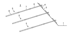
図1において、1は構築構造で形成される道路、2は地盤、3はこの地盤2の斜面、4はこの斜面3に設置される壁面ブロックである。
地盤2には、強度向上のために、壁面ブロック4の背面で、複数本の螺旋材(以下、この実施例では「アンカー」という。)5が上下方向で所定間隔に押し込まれて設置されている。
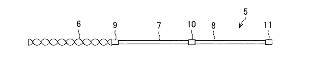
このアンカー5は、少なくとも一部にスクリュー部6を備えるものであって、図2に示すように、スクリュー部6と、接続ロッドとして、例えば、2本の第1、第2接続ロッド7、8とからなり、つまり、前端側で所定長さのスクリュー部6の後端のスクリュー端部9に所定長さの第1接続ロッド7の前端を接続し、この第1接続ロッド7の後端の第1端部10に所定長さの第2接続ロッド8の前端を接続している。この第2接続ロッド8は、後端に第2端部11を備えている。
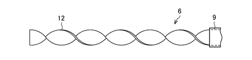
スクリュー部6は、図3に示すように、細長く且つ薄い一枚の金属板12をねじった螺旋形状に形成されている。
1 to 16 show an embodiment of the present invention.
In FIG. 1, 1 is a road formed by a construction structure, 2 is the ground, 3 is a slope of the
In order to improve the strength, a plurality of spiral members (hereinafter referred to as “anchors” in this embodiment) 5 are pushed into the
This
As shown in FIG. 3, the
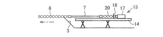
アンカー5は、図4に示すように、押込装置13によって地盤2に押し込まれる。
この押込装置13は、設置台部14が備えられた装置用架台15と、設置台部14上で移動可能な可動式スリット板16及び可動式螺旋材押込機17とを備えている。
装置用架台15は、前端が斜面3付近に向かって配置された直線状の設置台部14と、この設置台部14を支える複数の支持脚18・18とを備える。
可動式スリット板16は、図5、図6に示すように、所定の移動手段によって設置台部14に沿って移動可能に立設され、上下方向又は左右方向で細長いスリット部19を形成している。
このスリット部19は、スクリュー部6の金属板12を嵌入通過させるものであって、所定の幅Wで且つ所定の高さHに形成されている。従って、スクリュー部6の螺旋状態によって、スリット部19を通過するスクリュー部6の回転量や嵌入量が自動的に決定される。
可動式螺旋材押込機17は、所定の移動手段によって設置台部14に沿って移動可能に設けられ、且つ可動式スリット板16よりも設置台部14の後端側に配置され、アンカー5を、打設(ハンマー式)あるいは押圧(油圧式)し、回転させつつ地盤2に押し込むものである。
そして、押込装置13は、図5、図6に示すように、アンカー5のスクリュー部6を、可動式螺旋材押込機17の駆動によって、可動式スリット板16のスリット部19に嵌入通過させて所定に回転させつつ所定の貫入量(押込量)で、つまり、アンカー5の回転数と貫入量(押込量)とを適合させて、アンカー5を地盤2に押し込むものである。
As shown in FIG. 4, the
The pushing
The
As shown in FIGS. 5 and 6, the
The
The movable spiral
Then, as shown in FIGS. 5 and 6, the pushing
次いで、このアンカー5の施工方法について説明する。
図8に示すように、装置用架台15の設置台部14上で、アンカー5のスクリュー部6の前端を、設置台部14の前端部に設置、つまり、設置台部14の前端部に固定状態にした可動式スリット板16のスリット部19に嵌入通過するとともに、スクリュー部6の後端のスクリュー端部9を可動式螺旋材押込機17に支持する。
そして、図9に示すように、可動式螺旋材押込機17を駆動して押進すると、図5、図6に示すように、スクリュー部6が、可動式スリット板16のスリット部19の内周面に接して、所定に回転しつつ、所定の貫入量(押込量)でスリット部19に押し込まれる。これにより、地盤2には、スクリュー部6が確実に所定の貫入量(押込量)で押し込まれて行く。従って、スクリュー部6を地盤2に確実に押し込むことが可能となる。
Next, a construction method of the
As shown in FIG. 8, the front end of the
Then, as shown in FIG. 9, when the movable spiral
その後、図9に示すように、スクリュー部6のスクリュー端部9が設置台部14の前端部に達した際に、図10に示すように、可動式スリット板16を設置台部14の後端部に移動して設置(固定状態)する。
そして、図10に示すように、設置台部14の前端部で、地盤2に押し込まれたスクリュー部6の後端であるスクリュー端部9に第1接続ロッド7の前端を接続するとともに、設置台部14の後端部では、可動式スリット板16のスリット部19に後方から通過させた押進補助用スクリュー部材20の前端を第1接続ロッド7の後端である第1端部10に接続し、また、この押進補助用スクリュー部材20の後端を可動式螺旋材押込機17に支持する。
押進補助用スクリュー部材20は、図7に示すように、スクリュー部6と同様に(図3参照)、所定の長さの金属板を螺旋形状に形成されたものであり、ここでは、その詳細な説明を省略する。
After that, as shown in FIG. 9, when the
And as shown in FIG. 10, while connecting the front end of the
As shown in FIG. 7, the pushing assisting
そして、図11に示すように、可動式螺旋材押込機17を駆動して押進すると、図5、図6に示すように、押進補助用スクリュー部材20が、可動式スリット板16のスリット部19の内周面に接して、所定に回転しつつ、所定の貫入量(押込量)でスリット部19に押し込まれる。これにより、図11に示すように、地盤2には、スクリュー部6が確実に押し込まれて行く。従って、スクリュー部6を地盤2に確実に押し込むことが可能となる。
図12には、可動式スリット板16をさらに前方で設置台部14上に設置し、且つ可動式螺旋材押込機17を可動式スリット板16付近まで押進した状態を示す。これにより、地盤2には、スクリュー部6及び第1接続ロッド7が確実に押し込まれて行く。
その後、図13に示すように、第1接続ロッド7の後端の第1端部10が斜面3に達した際に、図14に示すように、可動式スリット板16を設置台部14上で移動して設置する。
そして、図14に示すように、第1接続ロッド7の後端である第1端部10に第2接続ロッド8の前端を接続するとともに、可動式スリット板16のスリット部19に後方から通過させた押進補助用スクリュー部材20の前端を第2接続ロッド8の後端である第2端部11に接続し、また、この押進補助用スクリュー部材20の後端を可動式螺旋材押込機17に支持する。
Then, as shown in FIG. 11, when the movable spiral
FIG. 12 shows a state in which the
Thereafter, as shown in FIG. 13, when the
And as shown in FIG. 14, while connecting the front-end of the
そして、図15に示すように、可動式スリット板16を設置台部14の前端部に設置し、且つ可動式螺旋材押込機17を駆動して押進すると、押進補助用スクリュー部材20が、可動式スリット板16のスリット部19の内周面に接して、所定に回転しつつ、所定の貫入量(押込量)でスリット部19に押し込まれる。これにより、地盤2には、スクリュー部6及び第1接続ロッド7・第2接続ロッド8が、確実にさらに深く押し込まれる。
そして、第2接続ロッド8の第2端部11が斜面3に達したときに、図16に示すように、この第2接続ロッド8の第2端部11を、可動式螺旋材押込機17から外して、斜面3の壁面プレート5に連結する。
Then, as shown in FIG. 15, when the
And when the
また、この実施例において、螺旋材としてのアンカーの変形例として、図17に示すように、アンカー5は、スクリュー部6と一本の第1接続ロッド7とから構成することも可能である。
この場合、このアンカー5は、上記の図8〜図13の手順で地盤2に押し込まれることから、ここでは、その詳細な説明を省略する。
Further, in this embodiment, as a modified example of the anchor as the spiral member, as shown in FIG. 17, the
In this case, since the
更に、他の螺旋材としてのアンカーの変形例として、図18に示すように、アンカー5は、全体がスクリュー部6からなる。
この場合、図19に示すように、押込架台15の設置台部14上で、アンカー5のスクリュー部6の前端を、設置台部14の前端部位に設置した可動式スリット板16のスリット部19に嵌入通過するとともに、スクリュー部6の後端のスクリュー端部9を可動式螺旋材押込機17で支持する。
Furthermore, as a modification of the anchor as another spiral member, the
In this case, as shown in FIG. 19, the
そして、図20に示すように、可動式螺旋材押込機17を駆動して押進すると、スクリュー部6が、可動式スリット板16のスリット部19の内周面に接して、所定に回転しつつ所定の貫入量(押込量)で、地盤2に押し込まれる。これにより、地盤2には、スクリュー部6が、確実に所定の押込量で押し込まれて行く。
その後、スクリュー部6の後端のスクリュー端部9が設置台部14の前端部に達した際に、図21に示すように、可動式螺旋材押込機17を設置台部14上で移動する。
Then, as shown in FIG. 20, when the movable spiral
Thereafter, when the
そして、図21に示すように、設置台部14の前端部でスクリュー部6のスクリュー端部9に、可動式スリット板16のスリット部19に後方から通過させた押進補助用スクリュー部材20の前端を接続し、また、この押進補助用スクリュー部材20の後端を可動式螺旋材押込機17に支持する。
そして、図22に示すように、可動式螺旋材押込機17を駆動して押進すると、押進補助用スクリュー部材20が、可動式スリット板16のスリット部19の内周面に接して、所定に回転しつつ、所定の貫入量(押込量)でスリット部19に押し込まれる。これにより、地盤2には、スクリュー部6が確実に押し込まれる。
そして、スクリュー部6のスクリュー端部9が斜面3に達したときに、図23に示すように、このスクリュー部6のスクリュー端部9を、可動式螺旋材押込機17から外して、斜面3の壁面プレート5に連結する。
Then, as shown in FIG. 21, the push assisting
Then, as shown in FIG. 22, when the movable spiral
When the
この発明に係る螺旋材の地盤埋設方法を、道路斜面以外の他の構築として、杭(パイル)等にも適用できる。 The ground material embedding method according to the present invention can be applied to piles or the like as construction other than road slopes.
1 道路
2 地盤
3 斜面
4 壁面ブロック
5 アンカー(螺旋材)
6 スクリュー部
7 第1接続ロッド
8 第2接続ロッド
13 押込装置
14 設置台部
15 装置用架台
16 可動式スリット板
17 可動式螺旋材押込機
19 スリット部
20 押進補助用スクリュー部材
1
6 Screw
Claims (1)
設置台部が備えられた装置用架台と前記設置台部上で移動可能な可動式スリット板及び可動式螺旋材押込機とを備えた押込装置を設け、
前記螺旋材は、前端が前記地盤に押し込まれて行くスクリュー部と、前端が前記スクリュー部の後端に接続される接続ロッドとを備え、
前端が前記接続ロッドの後端に接続されるとともに後端が前記可動式螺旋材押込機に支持される押進補助用スクリュー部材を設け、
前記可動式スリット板を固定状態で前記可動式螺旋材押込機を駆動して押進することにより、前記スクリュー部を前記可動式スリット板のスリット部に嵌入通過させて所定に回転させ、前記スクリュー部を所定の貫入量で前記地盤に押し込み、
その後、前記可動式スリット板を前記設置台部上で移動し、前記地盤に押し込まれた前記スクリュー部の後端に前記接続ロッドの前端を接続し、前記押進補助用スクリュー部材を前記可動式スリット板の前記スリット部に後方から通過させ、前記接続ロッドの後端に前記押進補助用スクリュー部材の前端を接続し、前記押進補助用スクリュー部材の後端を前記可動式螺旋材押込機に支持し、
そして、前記可動式スリット板を固定状態で前記可動式螺旋材押込機を駆動して押進することにより、前記押進補助用スクリュー部材を前記可動式スリット板の前記スリット部に嵌入通過させて所定に回転させ、前記スクリュー部及び前記接続ロッドを所定の貫入量で前記地盤に押し込むことを特徴とする螺旋材の地盤埋設方法。 In the ground burying method of the spiral material in which the spiral material is pushed into the ground and installed,
A device mounting device provided with an installation table, a movable slit plate movable on the installation table and a pushing device provided with a movable spiral material pushing machine,
The spiral member includes a screw portion whose front end is pushed into the ground, and a connecting rod whose front end is connected to the rear end of the screw portion,
A front end is connected to the rear end of the connecting rod, and a rear end is provided with a pushing assisting screw member supported by the movable spiral material pushing machine,
By pushing by driving the movable spiral member press-in machine in a fixed state the movable slit plate, by rotating the screw portion in a predetermined and is fitted passing the slit of the movable slit plate, the screw part push to the ground at a predetermined penetration amount,
Thereafter, the movable slit plate is moved on the installation base, the front end of the connecting rod is connected to the rear end of the screw portion pushed into the ground, and the pushing assisting screw member is moved to the movable type. Passing from the rear to the slit portion of the slit plate, connecting the front end of the push assisting screw member to the rear end of the connecting rod, and connecting the rear end of the push assisting screw member to the movable spiral material pushing machine To support
Then, by driving the movable spiral plate pushing machine and driving the movable slit plate in a fixed state, the pushing assisting screw member is inserted and passed through the slit portion of the movable slit plate. A method for embedding a spiral material , wherein the screw portion and the connecting rod are pushed into the ground with a predetermined penetration amount after being rotated to a predetermined degree .
Priority Applications (1)
| Application Number | Priority Date | Filing Date | Title |
|---|---|---|---|
| JP2010284467A JP5602003B2 (en) | 2010-12-21 | 2010-12-21 | Method of burying spiral material |
Applications Claiming Priority (1)
| Application Number | Priority Date | Filing Date | Title |
|---|---|---|---|
| JP2010284467A JP5602003B2 (en) | 2010-12-21 | 2010-12-21 | Method of burying spiral material |
Publications (2)
| Publication Number | Publication Date |
|---|---|
| JP2012132193A JP2012132193A (en) | 2012-07-12 |
| JP5602003B2 true JP5602003B2 (en) | 2014-10-08 |
Family
ID=46648091
Family Applications (1)
| Application Number | Title | Priority Date | Filing Date |
|---|---|---|---|
| JP2010284467A Expired - Fee Related JP5602003B2 (en) | 2010-12-21 | 2010-12-21 | Method of burying spiral material |
Country Status (1)
| Country | Link |
|---|---|
| JP (1) | JP5602003B2 (en) |
Family Cites Families (2)
| Publication number | Priority date | Publication date | Assignee | Title |
|---|---|---|---|---|
| JPS5420764B2 (en) * | 1974-05-29 | 1979-07-25 | ||
| JP5090804B2 (en) * | 2007-07-02 | 2012-12-05 | 株式会社Wasc基礎地盤研究所 | Construction method and foundation support structure of ready-made piles |
-
2010
- 2010-12-21 JP JP2010284467A patent/JP5602003B2/en not_active Expired - Fee Related
Also Published As
| Publication number | Publication date |
|---|---|
| JP2012132193A (en) | 2012-07-12 |
Similar Documents
| Publication | Publication Date | Title |
|---|---|---|
| KR100958696B1 (en) | Pretension nail method using wedge force | |
| CN106120821B (en) | A kind of interior root-type anchoring support device and its slope anchorage method for protecting support | |
| JP2009197539A (en) | Pillar supporting tool | |
| KR101714907B1 (en) | Sheet Pile Construction Apparatus | |
| JP5602003B2 (en) | Method of burying spiral material | |
| JP6795354B2 (en) | Support erection device | |
| JP6502287B2 (en) | Pile and pile installation method | |
| JP6215858B2 (en) | Micropile method and spacer for reinforcing material used in micropile method | |
| JP6513470B2 (en) | Foundation pile for installation, foundation pile for installation of solar panels, installation method of foundation pile and installation method of foundation pile for solar panels | |
| JP6424061B2 (en) | Foundation pile and its installation method | |
| JP5426424B2 (en) | Method for placing ground reinforcing pile and rod for preceding excavation and casting apparatus used therefor | |
| US20090309007A1 (en) | Concrete form anchor device, system and method for forming trenches | |
| JP2007247308A (en) | Pulling-out bearing strength reinforcing for pile group comprised of inclined piles and structure constructed according to the same | |
| JP2009197463A (en) | Base and fixing device for base and columnar body | |
| JP7592540B2 (en) | Pile driving casing and pile driving method | |
| JP2005061171A (en) | Pile head structure of pile foundation and construction method of pile head of pile foundation | |
| JP2008190181A (en) | Masonry retaining wall | |
| JP5881115B2 (en) | Pile | |
| JP2016153551A (en) | Foundation pile of building, and installation method thereof | |
| JP2003293364A (en) | Method for constructing pile | |
| JP4594224B2 (en) | Pile head reinforcement structure for steel pipe pile construction and steel pipe pile construction method | |
| JP2013194456A (en) | Inclined pile construction method | |
| KR101880687B1 (en) | Self-recovery module and method for constructing thereof | |
| JP4312135B2 (en) | Steel pipe sheet pile placing method | |
| JP2008075447A (en) | Soil improvement method |
Legal Events
| Date | Code | Title | Description |
|---|---|---|---|
| A621 | Written request for application examination |
Free format text: JAPANESE INTERMEDIATE CODE: A621 Effective date: 20131023 |
|
| A977 | Report on retrieval |
Free format text: JAPANESE INTERMEDIATE CODE: A971007 Effective date: 20140421 |
|
| A131 | Notification of reasons for refusal |
Free format text: JAPANESE INTERMEDIATE CODE: A131 Effective date: 20140423 |
|
| A521 | Request for written amendment filed |
Free format text: JAPANESE INTERMEDIATE CODE: A523 Effective date: 20140620 |
|
| TRDD | Decision of grant or rejection written | ||
| A01 | Written decision to grant a patent or to grant a registration (utility model) |
Free format text: JAPANESE INTERMEDIATE CODE: A01 Effective date: 20140729 |
|
| A61 | First payment of annual fees (during grant procedure) |
Free format text: JAPANESE INTERMEDIATE CODE: A61 Effective date: 20140819 |
|
| R150 | Certificate of patent or registration of utility model |
Ref document number: 5602003 Country of ref document: JP Free format text: JAPANESE INTERMEDIATE CODE: R150 |
|
| R250 | Receipt of annual fees |
Free format text: JAPANESE INTERMEDIATE CODE: R250 |
|
| S531 | Written request for registration of change of domicile |
Free format text: JAPANESE INTERMEDIATE CODE: R313531 |
|
| R350 | Written notification of registration of transfer |
Free format text: JAPANESE INTERMEDIATE CODE: R350 |
|
| RD03 | Notification of appointment of power of attorney |
Free format text: JAPANESE INTERMEDIATE CODE: R3D03 |
|
| R250 | Receipt of annual fees |
Free format text: JAPANESE INTERMEDIATE CODE: R250 |
|
| R250 | Receipt of annual fees |
Free format text: JAPANESE INTERMEDIATE CODE: R250 |
|
| R250 | Receipt of annual fees |
Free format text: JAPANESE INTERMEDIATE CODE: R250 |
|
| LAPS | Cancellation because of no payment of annual fees |