JP5598138B2 - Method for manufacturing pipe-type thermoelectric power generation device, and method for manufacturing the laminate - Google Patents
Method for manufacturing pipe-type thermoelectric power generation device, and method for manufacturing the laminate Download PDFInfo
- Publication number
- JP5598138B2 JP5598138B2 JP2010171632A JP2010171632A JP5598138B2 JP 5598138 B2 JP5598138 B2 JP 5598138B2 JP 2010171632 A JP2010171632 A JP 2010171632A JP 2010171632 A JP2010171632 A JP 2010171632A JP 5598138 B2 JP5598138 B2 JP 5598138B2
- Authority
- JP
- Japan
- Prior art keywords
- pipe
- power generation
- generation device
- cup
- laminate
- Prior art date
- Legal status (The legal status is an assumption and is not a legal conclusion. Google has not performed a legal analysis and makes no representation as to the accuracy of the status listed.)
- Active
Links
Images


Classifications
-
- Y—GENERAL TAGGING OF NEW TECHNOLOGICAL DEVELOPMENTS; GENERAL TAGGING OF CROSS-SECTIONAL TECHNOLOGIES SPANNING OVER SEVERAL SECTIONS OF THE IPC; TECHNICAL SUBJECTS COVERED BY FORMER USPC CROSS-REFERENCE ART COLLECTIONS [XRACs] AND DIGESTS
- Y02—TECHNOLOGIES OR APPLICATIONS FOR MITIGATION OR ADAPTATION AGAINST CLIMATE CHANGE
- Y02E—REDUCTION OF GREENHOUSE GAS [GHG] EMISSIONS, RELATED TO ENERGY GENERATION, TRANSMISSION OR DISTRIBUTION
- Y02E20/00—Combustion technologies with mitigation potential
- Y02E20/14—Combined heat and power generation [CHP]
-
- Y—GENERAL TAGGING OF NEW TECHNOLOGICAL DEVELOPMENTS; GENERAL TAGGING OF CROSS-SECTIONAL TECHNOLOGIES SPANNING OVER SEVERAL SECTIONS OF THE IPC; TECHNICAL SUBJECTS COVERED BY FORMER USPC CROSS-REFERENCE ART COLLECTIONS [XRACs] AND DIGESTS
- Y02—TECHNOLOGIES OR APPLICATIONS FOR MITIGATION OR ADAPTATION AGAINST CLIMATE CHANGE
- Y02P—CLIMATE CHANGE MITIGATION TECHNOLOGIES IN THE PRODUCTION OR PROCESSING OF GOODS
- Y02P70/00—Climate change mitigation technologies in the production process for final industrial or consumer products
- Y02P70/50—Manufacturing or production processes characterised by the final manufactured product
Description
本発明は熱エネルギーから電気エネルギーへの変換を行う熱発電デバイスに関する。 The present invention relates to a thermoelectric power generation device that converts thermal energy into electrical energy.
熱発電は、物質の両端に印加された温度差に比例して起電力が生じるゼーベック効果を利用し、熱エネルギーを直接電気エネルギーに変換する技術である。この技術は、僻地用電源、宇宙用電源、軍事用電源等で実用化されている。 Thermoelectric power generation is a technology that directly converts thermal energy into electrical energy using the Seebeck effect in which an electromotive force is generated in proportion to the temperature difference applied to both ends of a substance. This technology has been put to practical use in remote power supplies, space power supplies, military power supplies, and the like.
従来の熱発電デバイスは、キャリアの符号が異なるP型半導体とN型半導体を組み合わせ、熱的に並列に、かつ電気的に直列につないだ、いわゆるπ型構造と呼ばれる平板状の構造を有している。この平板状のデバイスの一方の面を熱源に接触させ、他方の面を冷却することによってデバイスに温度差を生じさせ、発電を行うような構成となっている。 A conventional thermoelectric power generation device has a plate-like structure called a π-type structure that combines a P-type semiconductor and an N-type semiconductor with different carrier codes, and is connected in parallel and electrically in series. ing. By making one surface of the flat device contact a heat source and cooling the other surface, a temperature difference is generated in the device to generate power.
また、本発明者らは金属と熱電材料であるBiとからなる異種材料の積層構造における熱電気特性の異方性を利用したデバイスにおいて、積層体における各材料の厚さの比(以下、積層比と書く)と積層方向の傾斜角度を適切に選択することによって優れた発電性能が実現することを見いだし、これを利用した熱発電デバイスを発明した(特許文献1)。 In addition, in the device utilizing the anisotropy of thermoelectric properties in a laminated structure of different materials composed of a metal and Bi, which is a thermoelectric material, the inventors of the present invention have a thickness ratio of each material in a laminated body (hereinafter referred to as a laminated material). We have found that excellent power generation performance is realized by appropriately selecting the inclination angle in the stacking direction and invented a thermoelectric power generation device using this (Patent Document 1).
しかしながら前記従来のπ型構造や、特許文献1に記載のデバイス構造はどれも平板状の構造を有している。したがって、温水や高温の排気ガスなどの熱源から集熱を行い、発電を行うためには、流体熱源が流れる配管と熱発電デバイスとの間に生じる隙間を何らかの形で埋める工程を設けたり、配管の表面を平面にしなければならなかったりと制約が大きかった。さらに、熱源と熱発電デバイスとの接続に熱伝導性グリースや接着剤、両面テープ等を用いなければならず、熱源から効率よく集熱を行うことができなかった。これは冷却を行う放熱部についても同様である。
However, the conventional π-type structure and the device structure described in
前述の通り、従来の熱電変換デバイスでは、集熱および放熱構造の制約が大きく、効率よく集熱を行うことができない。従って多くの用途で実用に足るだけの熱発電を行うことができない。 As described above, in the conventional thermoelectric conversion device, heat collection and heat dissipation structure are largely restricted, and heat collection cannot be performed efficiently. Therefore, thermoelectric power generation sufficient for practical use cannot be performed in many applications.
本発明は、前記従来の課題を解決するもので、高い発電特性を達成するために、流体熱源との良好な熱伝達が可能となる単純な構造を有するパイプ型の熱発電デバイス、および、その積層体の製造方法を提供することを目的とする。 The present invention solves the above-mentioned conventional problems, and in order to achieve high power generation characteristics, a pipe-type thermoelectric power generation device having a simple structure that enables good heat transfer with a fluid heat source, and It aims at providing the manufacturing method of a laminated body.
前記従来の課題を解決するために、本発明のパイプ型熱発電デバイスの製造方法は、金属からなる部材と熱電材料からなる部材を交互に積層する工程と、積層された部材を接合する工程と、電極を接続する工程からなる。 In order to solve the above-described conventional problems, a method for manufacturing a pipe-type thermoelectric power generation device according to the present invention includes a step of alternately laminating members made of metal and a member made of a thermoelectric material, and a step of joining the laminated members. And the step of connecting the electrodes.
本発明のパイプ型熱発電デバイスの製造方法により、流体熱源との熱伝達が良好なパイプ型熱発電デバイス、および、その積層体を製造することができる。 By the method for manufacturing a pipe-type thermoelectric power generation device of the present invention, a pipe-type thermoelectric power generation device having good heat transfer with a fluid heat source and a laminate thereof can be manufactured.
以下本発明の実施の形態について、図面を参照しながら説明する。 Embodiments of the present invention will be described below with reference to the drawings.
(実施の形態1)
図1は、本実施の形態におけるパイプ型熱発電デバイスの製造工程を示したものである。本実施の形態における熱発電デバイスの製造工程は、金属と熱電材料からなる傾斜積層体を用意する工程(S1)と、金属と熱電材料を接合する工程(S2)と、積層体の両端に第1電極および第2電極を作製する工程(S3)、とからなる。
(Embodiment 1)
FIG. 1 shows a manufacturing process of a pipe-type thermoelectric power generation device in the present embodiment. The manufacturing process of the thermoelectric power generation device in the present embodiment includes a step (S1) of preparing an inclined laminated body made of a metal and a thermoelectric material, a step (S2) of joining the metal and the thermoelectric material, A step of producing one electrode and a second electrode (S3).
より具体的には、例えば図3に示したように、金属または熱電材料からなるカップ状の部材を製造する工程(S11)と、金属からなる部材と熱電材料からなる部材を交互に積層し、接合する工程(S12)を経て金属と熱電材料からなる傾斜積層体を製造することができる。熱発電デバイスを用いて熱発電させるためには、このデバイスの両端に電極が必要であるため、積層体を挟むように第1電極と第2電極を作製する工程(S13)が必要となる。ただし、この第1電極と第2電極とを作成する工程は、積層体の作成時でなくても良い。また、積層体のみを製造する場合は、S1とS2との工程を実行すれば足りる。より詳細な製造構成は後述する。 More specifically, for example, as shown in FIG. 3, a step of manufacturing a cup-shaped member made of a metal or a thermoelectric material (S11), a member made of a metal and a member made of a thermoelectric material are alternately laminated, Through the joining step (S12), an inclined laminate made of a metal and a thermoelectric material can be manufactured. In order to generate thermoelectric power using a thermoelectric power generation device, electrodes are required at both ends of the device, and thus a step (S13) of producing the first electrode and the second electrode so as to sandwich the laminate is necessary. However, the step of creating the first electrode and the second electrode may not be performed at the time of creating the laminate. Moreover, when only a laminated body is manufactured, it is sufficient to perform the steps S1 and S2. A more detailed manufacturing configuration will be described later.
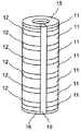
本発明のパイプ型熱発電デバイスの製造方法によって実現されるパイプ型熱発電デバイスは、図3に一例を示したとおり、金属11および熱電材料12が交互に一定の積層比で積層されたパイプ状の積層体の両端を第1電極15および第2電極16で挟み込んだような構造である。また、その内部には、貫通孔を有している。また、図4の断面図に示したように、金属11と熱電材料12の積層面は貫通孔の軸方向23に対して一定の角度θで傾斜している。さらに、この積層面は、積層した際に積層界面に隙間ができにくいようになっている。なお、貫通孔は貫通構造を有していればその断面形状は円に限定されず、図5のような楕円、図6のような多角形、あるいは不定形の形状でもよい。
The pipe-type thermoelectric power generation device realized by the method for manufacturing a pipe-type thermoelectric power generation device of the present invention is a pipe-like structure in which the
角度θの好適な範囲は金属11と熱電材料12との組み合わせによって異なる。例えばCuとBiの組み合わせであればθは5°以上45°以下の範囲が好ましい。
A suitable range of the angle θ varies depending on the combination of the
金属11と熱電材料12の間に隙間が無いように、金属11と熱電材料12を積層することで、熱発電デバイスの内側(貫通孔内)と外側それぞれを流れる流体が互いに混ざらないようにすることができる。図3において、内側の流体21が高温流体の場合は外側の流体22は低温流体とし、また内側の流体21が低温流体の場合は外側の流体22は高温流体とする。
By laminating the
これにより、デバイスの内側と外側との間に温度差が生じ、発電を行うことができる。発電された電力はパイプ型熱発電デバイスの両端に設けられた第1電極15および第2電極16に電気負荷を接続するなどして取り出すことができる。
Thereby, a temperature difference arises between the inner side and the outer side of the device, and power generation can be performed. The generated electric power can be taken out by connecting an electric load to the
また、図7に示すように、金属11と熱電材料12の積層体において、溝部19を設ける事もできる。溝部19には積層体が電気的に短絡しないよう、電気絶縁体を充填する事が好ましい。溝部19に弾力性のある樹脂などを充填すれば、積層体に加わる熱応力を緩和することもできる。溝部19は単なる切り欠きとし、中空にすることも勿論可能である。さらに、図8のように、第1電極15および第2電極16の端部をパイプ形状とすれば、積層体の内筒部に流体を導入することが容易となり、より実用的なパイプ型熱発電デバイスが実現する。
Further, as shown in FIG. 7, a
なお、金属11は、電気伝導および熱伝導の良い材料であれば特に限定されない。具体的にはCu、Ag、Al、Au等が良い。
The
また、熱電材料12は、Bi、Bi2Te3あるいはSb、SeなどによるドーピングしたBi、Bi2Te3、YbAl3、PbTeなどが良いが、これらに限定されるものではなく、様々な熱電材料を用いることができる。
The
また、第1電極15および第2電極16は電気伝導の良い材料であれば特に限定されない。パイプ構造の両端に金属11を配置する構成にすれば、第1電極15および第2電極16を省略することもできる。
The
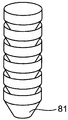
実施の形態1のパイプ型熱発電デバイスの製造工程について、より詳細に説明する。まず図9に示したように、カップ型の金属からなる部材81と、カップ型の熱電材料からなる部材82をそれぞれ必要な数だけ作製する(図1のS1)。カップ型の部材の断面は図10に示したように内側面92、外側面93および貫通孔の軸91に対して一定の傾斜角度θを有する2つのテーパー面からなる。
The manufacturing process of the pipe-type thermoelectric power generation device according to the first embodiment will be described in more detail. First, as shown in FIG. 9, a necessary number of
カップ型の部材の作製には様々な方法が利用できる。例えば、切削加工、放電加工、鋳造加工、塑性加工、原料粉体を型に入れて焼結するなどの方法を用いることができる。中でもプレス加工などに代表される塑性加工は量産に適しているので好ましい。 Various methods can be used for producing the cup-shaped member. For example, methods such as cutting, electric discharge machining, casting, plastic working, and putting raw material powder into a mold and sintering can be used. Of these, plastic working such as press working is preferable because it is suitable for mass production.
次に金属の部材と熱電材料の部材を交互に積層し、接合する工程(図1のS2)について説明する。まずS1の工程で作製されたカップ型の金属の部材と熱電材料の部材を交互に積層して、全体としてパイプ形状の積層構造となるようにする。カップ型の部材は内部に貫通孔を有しているので、この貫通孔に対してガイドの役割を果たす棒あるいはワイヤーを通すことで容易に多数の部材を積層することができる。こうして積層された部材の接合には、高温雰囲気で圧力を加えるホットプレスや、積層体そのものに通電し加熱を行い、同時に圧力を加える放電プラズマ焼結などの方法を用いることができる。また、銀ペーストやはんだなどを用い、金属と熱電材料の部材を積層する工程と同時に接合を形成することもできる。 Next, a process of alternately laminating and joining metal members and thermoelectric material members (S2 in FIG. 1) will be described. First, cup-shaped metal members and thermoelectric material members produced in the step S1 are alternately laminated so that a pipe-like laminated structure is obtained as a whole. Since the cup-shaped member has a through-hole inside, a large number of members can be easily laminated by passing a rod or wire serving as a guide through the through-hole. For the joining of the members thus laminated, a method such as hot pressing in which pressure is applied in a high temperature atmosphere, or discharge plasma sintering in which the laminated body itself is energized and heated and pressure is applied at the same time can be used. In addition, a joint can be formed simultaneously with the step of laminating the metal and thermoelectric material members using silver paste or solder.
第1電極15および第2電極16の作製方法(図1のS3)は、蒸着法、スパッタ法などの気相成長の他に、導電性ペーストの塗布、めっき、溶射、はんだによる接合など様々な方法を用いることができる。また、積層体の両端が金属からなる部材81で終端されていれば、これを第1電極15および第2電極16として用い、S3の工程を省くことができるのはもちろんである。電極の作製を容易にするために、積層体の両端を予め研削して平坦化するなどの処理を行っても良い。なお、S3の工程は積層体作成とは独立して作成しても良い。
The
本発明のパイプ型熱発電デバイスの製造方法においては、S2の工程において充分に長い積層体を作製した後で、必要な長さの複数の積層体に分割し、分割された各々の積層体に対して第1電極および第2電極の作製を行うこともできる。 In the method for manufacturing a pipe-type thermoelectric power generation device of the present invention, after a sufficiently long laminate is produced in the step S2, it is divided into a plurality of laminates having a required length, and each of the divided laminates is divided. On the other hand, the first electrode and the second electrode can also be produced.
(実施の形態2)
本発明のパイプ型熱発電デバイスの製造方法では、図1のS1の工程の一部とS2の工程の一部を同時に行うこともできる。例えば図11に示したように、まず内部に開口部を有する平板状の金属からなる部材および熱電材料からなる部材をそれぞれ作製する(図11のS21)。次に図12に示したように金属からなる部材101と熱電材料からなる部材102を交互に積層し、パンチ103とダイス104を用いたプレスによる塑性加工と積層体の接合加工を同時に行い、積層体を作製する(図11のS22)。なお、図12においてダイス104の一部は断面を示している。その後第1電極および第2電極を作製する(図11のS23)。
(Embodiment 2)
In the method for manufacturing a pipe-type thermoelectric power generation device of the present invention, part of the step S1 and part of the step S2 in FIG. 1 can be performed simultaneously. For example, as shown in FIG. 11, first, a member made of a flat metal having an opening inside and a member made of a thermoelectric material are respectively produced (S21 in FIG. 11). Next, as shown in FIG. 12,
金属からなる部材と熱電材料からなる部材の積層と接合を行う工程S22では、積層する部材の数が多すぎると各層の塑性変形の大きさのばらつきが顕著になる。したがって一度に加工する部材の数量は、あまり多くない方が好ましい。一度の加工で用いる部材の数量の好適な範囲は部材の寸法によって異なるが、20個以下が好ましく、10個以下がより好ましい。一度の加工で所望の長さの積層体が得られない場合は、工程S22を複数回繰り返し、得られる複数の積層体を一つに接合する工程を別途設ける必要がある(図11のS24)。 In step S22 in which the member made of metal and the member made of thermoelectric material are laminated and joined, if the number of members to be laminated is too large, the variation in the magnitude of plastic deformation of each layer becomes significant. Therefore, it is preferable that the number of members processed at a time is not so large. A suitable range of the number of members used in one processing varies depending on the dimensions of the members, but is preferably 20 or less, more preferably 10 or less. If a laminate with a desired length cannot be obtained by a single process, it is necessary to repeat step S22 a plurality of times and separately provide a step of joining the resulting laminates together (S24 in FIG. 11). .
工程S21の、内部に開口部を有する平板状の部材の作製には、鋳造など様々な方法を用いることができるが、板材の打ち抜きなどの剪断加工によれば容易に所望の部材を精度良く作製することができるので好ましい。 Various methods such as casting can be used for the production of the flat plate member having the opening in step S21, but the desired member can be easily and accurately produced by shearing such as punching a plate material. This is preferable.
工程S22の塑性加工においては、金属および熱電材料が固着しないカーボンなどからなるダイスを用いるのが好ましい。また、熱電材料が室温において脆性を示す場合、加熱しながら塑性加工を行うことによって部材の割れなどを防ぐことができる。塑性加工の際の加熱温度は、加工後の極端な寸法のずれを防ぐために熱電材料の融点以下であることが好ましい。また、塑性加工の際に積層体内部にマンドレルなどの芯金を挿入しても良い。 In the plastic working in step S22, it is preferable to use a die made of carbon or the like to which the metal and the thermoelectric material do not adhere. In addition, when the thermoelectric material is brittle at room temperature, cracking of the member can be prevented by performing plastic working while heating. The heating temperature during the plastic working is preferably equal to or lower than the melting point of the thermoelectric material in order to prevent an extreme dimensional shift after the working. Further, a cored bar such as a mandrel may be inserted into the laminated body during plastic working.
第1電極15および第2電極16の作製方法(図1のS23)は、蒸着法、スパッタ法などの気相成長の他に、導電性ペーストの塗布、めっき、溶射、はんだによる接合など様々な方法を用いることができる。また、積層体の両端が金属からなる部材81で終端されていれば、これを第1電極15および第2電極16として用い、S3の工程を省くことができるのはもちろんである。電極の作製を容易にするために、積層体の両端を予め研削して平坦化するなどの処理を行っても良い。なお、S3の工程は積層体作成とは独立して作成しても良い。
The
また、積層体のみを製造する場合は、S1とS2との工程を実行すれば足りる。 Moreover, when only a laminated body is manufactured, it is sufficient to perform the steps S1 and S2.
(実施の形態3)
本実施の形態におけるパイプ型熱発電デバイスの製造方法の工程を図13に示す。まず内部に開口部を有する平板状の金属からなる部材および熱電材料からなる部材をそれぞれ作製する(図13のS31)。次に金属からなる部材と熱電材料からなる部材を交互に積層し、接合してパイプ形状の積層体を作製する(図13のS32)。その後押し出しあるいは引き抜きなどの塑性加工によって金属と熱電材料の積層面が開口部の軸に対して傾斜したパイプ形状の積層体に加工する(図13のS33)。次に第1電極および第2電極を作製する(図13のS34)。
(Embodiment 3)
FIG. 13 shows the steps of the method for manufacturing the pipe-type thermoelectric power generation device in the present embodiment. First, a member made of a flat metal having an opening inside and a member made of a thermoelectric material are respectively produced (S31 in FIG. 13). Next, a member made of a metal and a member made of a thermoelectric material are alternately laminated and joined to produce a pipe-shaped laminate (S32 in FIG. 13). Thereafter, the laminated surface of the metal and the thermoelectric material is processed into a pipe-shaped laminate in which the laminated surface of the metal and the thermoelectric material is inclined with respect to the axis of the opening by plastic working such as extrusion or drawing (S33 in FIG. 13). Next, the first electrode and the second electrode are produced (S34 in FIG. 13).
工程S31の、内部に開口部を有する平板状の部材の作製には、鋳造など様々な方法を用いることができるが、板材の打ち抜きなどの剪断加工によれば容易に所望の部材を精度良く作製することができるので好ましい。 Various methods such as casting can be used to produce a flat plate member having an opening in step S31, but a desired member can be easily and accurately produced by shearing such as punching a plate material. This is preferable.
パイプ形状の積層体を作製する工程S32では、S31の工程で作製された内部に開口部を有する平板状の金属の部材と熱電材料の部材を交互に積層して、全体としてパイプ形状の積層構造となるようにする。平板状の部材は内部に貫通孔を有しているので、この貫通孔に対してガイドの役割を果たす棒あるいはワイヤーを通すことで容易に多数の部材を積層することができる。こうして積層された部材の接合には、高温雰囲気で圧力を加えるホットプレスや、積層体そのものに通電し加熱を行い、同時に圧力を加える放電プラズマ焼結などの方法を用いることができる。金属と熱電材料の間に銀ペーストやはんだなどの材料を挿入して接合を強化したり、接合界面の応力を緩和することもできる。 In the step S32 for producing the pipe-shaped laminate, the plate-shaped laminated structure having the openings formed in the step S31 is laminated alternately with the plate-like metal member and the thermoelectric material member as a whole. To be. Since the flat plate member has a through hole inside, a large number of members can be easily laminated by passing a rod or a wire serving as a guide through the through hole. For the joining of the members thus laminated, a method such as hot pressing in which pressure is applied in a high temperature atmosphere, or discharge plasma sintering in which the laminated body itself is energized and heated and pressure is applied at the same time can be used. A material such as silver paste or solder can be inserted between the metal and the thermoelectric material to strengthen the bonding, or the stress at the bonding interface can be relaxed.
工程S33における塑性加工の一例を図14に示す。図14では加工前の積層体111と加工後の積層体112の一部の断面、およびダイス113の断面を示した。工程S32で作製された金属と熱電材料からなるパイプ形状の積層体を、進行方向114に沿ってダイス113へと送る。加工前の積層体111における金属と熱電材料の積層面はパイプの軸に対して垂直であるが、加工後の積層体112では積層面はパイプの軸に対して垂直よりも浅い傾斜角度となる。また、積層体の肉厚は減ぜられる。本工程は加工前の積層体111に対して進行方向に押す、押し出し加工としても良いし、加工後の積層体112を進行方向に引く、引き抜き加工としても良い。また、押し出しと引き抜きを同時に行っても良い。加工後の積層体の内径を制御するために、積層体内部にマンドレルなどの芯金(図14では図示を省略)を挿入しながら加工を行うのが好ましい。
An example of plastic working in step S33 is shown in FIG. FIG. 14 shows a cross section of a part of the
第1電極15および第2電極16の作製方法(図13のS34)は、蒸着法、スパッタ法などの気相成長の他に、導電性ペーストの塗布、めっき、溶射、はんだによる接合など様々な方法を用いることができる。また、積層体の両端が金属からなる部材81で終端されていれば、これを第1電極15および第2電極16として用い、S3の工程を省くことができるのはもちろんである。電極の作製を容易にするために、積層体の両端を予め研削して平坦化するなどの処理を行っても良い。なお、S3の工程は積層体作成とは独立して作成しても良い。
There are various methods for producing the
また、積層体のみを製造する場合は、S1とS2との工程を実行すれば足りる。 Moreover, when only a laminated body is manufactured, it is sufficient to perform the steps S1 and S2.
(実施の形態4)
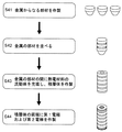
本実施の形態におけるパイプ型熱発電デバイスの製造方法の工程を図15に示す。本実施の形態における熱発電デバイスの製造工程は、カップ型の金属からなる部材を作製する工程(S41)と、金属からなる部材を並べる工程(S42)と、並べられた金属の部材の間に熱電材料からなる流動体を充填し、積層体を作製する工程(S43)と、からなる。熱発電デバイスを用いて熱発電させるためには、このデバイスの両端に電極が必要であるため、積層体を挟むように第1電極と第2電極を作製する工程(S44)が必要となる。ただし、この第1電極と第2電極とを作成する工程は、積層体の作成時でなくても良い。より詳細な製造構成は後述する。
(Embodiment 4)
FIG. 15 shows the steps of the method for manufacturing the pipe-type thermoelectric power generation device in the present embodiment. The manufacturing process of the thermoelectric generator in the present embodiment includes a step of producing a cup-shaped metal member (S41), a step of arranging metal members (S42), and the arranged metal members. Filling a fluid made of a thermoelectric material to produce a laminate (S43). In order to generate thermoelectric power using a thermoelectric power generation device, electrodes are required at both ends of the device, and therefore a step (S44) of producing the first electrode and the second electrode so as to sandwich the laminate is necessary. However, the step of creating the first electrode and the second electrode may not be performed at the time of creating the laminate. A more detailed manufacturing configuration will be described later.
カップ型の金属からなる部材を作製する工程(S42)には様々な方法が利用できる。例えば、切削加工、放電加工、鋳造加工、塑性加工、原料粉体を型に入れて焼結するなどの方法を用いることができる。中でもプレス加工などに代表される塑性加工は量産に適しているので好ましい。 Various methods can be used for the step (S42) of producing a member made of a cup-shaped metal. For example, methods such as cutting, electric discharge machining, casting, plastic working, and putting raw material powder into a mold and sintering can be used. Of these, plastic working such as press working is preferable because it is suitable for mass production.
金属からなる部材を並べる工程(S42)においては、最終的に意図したパイプ形状の積層体となるようにカップ型の金属からなる部材81を整列させることが好ましい。具体的には、図16に示したような直線状、あるいは図17に示したような曲線状に並べることができる。カップ型の金属からなる部材81の位置決めには、図18に示したように、内部に通した心棒171を用いることができる。また、後の工程で用いる鋳型に位置決めのガイドとなるような溝部などを設けることによってカップ型の金属からなる部材81を所定の位置に整列させることもできる。
In the step of arranging the metal members (S42), it is preferable to align the cup-shaped
金属の部材の間に熱電材料からなる流動体を充填し、積層体を作製する工程(S43)では、積層体の外形をなすような鋳型の中に並べられたカップ型の金属からなる部材81を配置し、隙間に熱電材料からなる流動体を充填する。鋳型に用いる材料は熱電材料あるいは金属と固着しないようなものを用いることが好ましい。具体的にはカーボン、セラミック、あるいはこれらでコーティングされた金属を用いることができる。また、積層体内部が中空構造となるよう、内部に心棒を配置することが好ましい。鋳型および心棒は積層体の作製後に基本的には取り外されるが、心棒がパイプ状の中空構造を有していればそのまま残しておいても良い。その場合は心棒と積層体との間は電気的に絶縁されている必要がある。
In the step (S43) of filling a fluid made of a thermoelectric material between metal members and producing a laminate (S43), a
第1電極15および第2電極16の作製方法(図15のS44)は、蒸着法、スパッタ法などの気相成長の他に、導電性ペーストの塗布、めっき、溶射、はんだによる接合など様々な方法を用いることができる。また、積層体の両端が金属からなる部材81で終端されていればこれを第1電極15および第2電極16として用い、S3の工程を省くことができるのはもちろんである。電極の作製を容易にするために、積層体の両端を予め研削して平坦化するなどの処理を行っても良い。なお、S3の工程は積層体作成とは独立して作成しても良い。
There are various methods for producing the
また、積層体のみを製造する場合は、S1とS2との工程を実行すれば足りる。 Moreover, when only a laminated body is manufactured, it is sufficient to perform the steps S1 and S2.
以下、本発明のより具体的な実施例を説明する。 Hereinafter, more specific examples of the present invention will be described.
金属11としてアルミニウムを、熱電材料12としてBi0.5Sb1.5Te3を用いて本発明のパイプ型熱発電デバイスを作製した。予め鋳造およびプレス加工によってアルミニウムとBi0.5Sb1.5Te3を図10のようなカップ状に成形した。カップ状のアルミニウムからなる部品は最大外径7mm、最小内径4mm、高さ6.2mm、傾斜角度20°とし、カップ状のBi0.5Sb1.5Te3からなる部品は最大外径7mm、最小内径4mm、高さ5mm、傾斜角度20°とした。これらの部品を積層した際の積層方向の厚みの比は無酸素銅:Bi0.5Sb1.5Te3=7:3である。また、カップ状の部品を積層した際の積層面は、積層方向に対して20°の角度となるようにした。200個のカップ状のBi0.5Sb1.5Te3からなる部品と、199個のカップ状のアルミニウムからなる部品を、両端におねじ部を有する外径4mmのステンレス製の丸棒に交互に通した後、両端に外径6mm、内径5mm、長さ50mmの銅パイプのついたカップ状の銅部品を取り付け、両端をナットで締め付けることにより固定した。この際、一方の端にナットを組み付ける前にインコネル製のばねを挿入しておくことで、カップ状の部品の積層方向に一定の圧力がかかるようにした。このようにして組み立てた部品をArフローした管状炉において、500℃で2時間加熱した。室温まで冷やした後で部品を取り出し、ナットおよび丸棒を取り外すと、両端部に銅パイプを備えた外径約7mm、内径約4mm、長さ約700mmの、アルミニウムとBi0.5Sb1.5Te3からなるパイプ型熱発電デバイスが得られた。
A pipe-type thermoelectric power generation device of the present invention was fabricated using aluminum as the
上述の手順で得られたパイプ型熱発電デバイスの両端部に第1電極および第2電極としてはんだを用いて2本の銅線を接続した。次にパイプ型熱発電デバイスの両端にシリコーンチューブを接続し、80℃の温水を循環させ、パイプ型熱発電デバイス全体を水温20℃に保持した水槽中に沈めたところ、2本の銅線の間から最大1530mWの電力を取り出すことができた。 Two copper wires were connected to both ends of the pipe-type thermoelectric power device obtained by the above procedure using solder as the first electrode and the second electrode. Next, a silicone tube was connected to both ends of the pipe-type thermoelectric power generation device, 80 ° C hot water was circulated, and the entire pipe-type thermoelectric power generation device was submerged in a water tank maintained at a water temperature of 20 ° C. A maximum of 1530mW of power could be extracted from between.
同様の作製方法、および無酸素銅とBi0.5Sb1.5Te3の厚みの比(7:3)で積層角度を5°、10°、20°、45°のパイプ状熱発電デバイスを作製し、同様の条件で評価を行ったところ、表1に示したような発電電力が得られた。 A pipe-shaped thermoelectric power generation device with a similar fabrication method and a stacking angle of 5 °, 10 °, 20 °, 45 ° with a ratio of oxygen-free copper to Bi 0.5 Sb 1.5 Te 3 thickness (7: 3), When the evaluation was performed under the same conditions, the generated power as shown in Table 1 was obtained.

金属11として無酸素銅を、熱電材料12としてBiを用いて、本発明のパイプ型熱発電デバイスを作製した。無酸素銅からなる部品は外径16mm、内径10mm、厚さ1.5mmの平板とし、Biからなる部品は外径16mm、内径10mm、厚さ0.5mmとした。これら無酸素銅とBiの部品を5個ずつ、計10枚交互に積層し、図12に示したようなダイスとパンチを用いてプレス加工を行った。プレス加工は230℃の窒素雰囲気中で、最大1000kgfの荷重をかけて行った。加工後の積層体は外径約13mm、内径約10mm、長さ約20mmの円筒形状であった。後述する測定を行った後、積層体を切断して無酸素銅とBiの積層面を観察したところ、積層面と円筒形状の軸とのなす傾斜角度は約30°であった。
Using the oxygen-free copper as the
上述した手順で、無酸素銅とBiからなる積層体を合計5個作製し、直線上に積み重ねた上で窒素雰囲気にて250℃に加熱しながらホットプレスを行い、長さ約100mmの積層体を作製した。その後、積層体の両端部にインジウムを用いて2本の銅線を接続した。次にパイプ型熱発電デバイスの両端にシリコーンチューブを圧入して接続しエポキシ接着剤によってチューブを固定した。パイプ型熱発電バイスの内部に80℃の温水を循環させ、パイプ型熱発電デバイス全体を水温20℃に保持した水槽中に沈めたところ、2本の銅線の間から最大140mWの電力を取り出すことができた。 5 layers of oxygen-free copper and Bi were prepared in the above procedure, stacked on a straight line, hot-pressed while heating to 250 ° C in a nitrogen atmosphere, and about 100 mm long Was made. Thereafter, two copper wires were connected to both ends of the laminate using indium. Next, a silicone tube was press-fitted into both ends of the pipe-type thermoelectric power generation device and connected, and the tube was fixed with an epoxy adhesive. Circulating 80 ° C hot water inside the pipe-type thermoelectric generator vise and submerging the entire pipe-type thermoelectric generator device in a water tank maintained at a water temperature of 20 ° C, taking out a maximum of 140mW of power from between the two copper wires I was able to.
金属11として無酸素銅を、熱電材料12としてPbTeを用いて本発明のパイプ型熱発電デバイスを作製した。無酸素銅からなる部品は外径20mm、内径15mm、厚さ1.2mmの平板とし、PbTeからなる部品は外径20mm、内径15mm、厚さ0.8mmとした。これら無酸素銅とPbTeの部品を50個ずつ、計100枚交互に積層し、外径15mmのステンレス棒に通した。この試料を、水素を3%含むアルゴン雰囲気中で500℃に加熱しながらホットプレスを行い、接合された長さ約100mmの積層体を作製した。
Using the oxygen-free copper as the
次にステンレス製のダイスを用いて図14に示したような塑性加工を行った。加工の際には円筒内部に潤滑油を塗布したステンレス製の外径15mmの丸棒を挿入しておき、積層体に押し出し荷重を加えておよそ毎分3mmの加工速度で塑性加工を行った。加工途中で適宜引き抜き荷重を加えて荷重を調整することによって加工速度を維持した。同様の塑性加工を合計5回繰り返し行い、外径約17mm、約内径15mm、長さ約270mmの無酸素銅とPbTeからなる円筒状の積層体を作製した。後述する測定を行った後、積層体を切断して無酸素銅とBiの積層面を観察したところ、積層面と円筒形状の軸とのなす傾斜角度は約25°であった。 Next, plastic working as shown in FIG. 14 was performed using a stainless steel die. At the time of processing, a stainless steel round bar with a 15 mm outer diameter coated with lubricating oil was inserted into the cylinder, and an extrusion load was applied to the laminate to perform plastic processing at a processing speed of about 3 mm per minute. The processing speed was maintained by adjusting the load by appropriately applying a drawing load during the processing. The same plastic working was repeated a total of 5 times to produce a cylindrical laminate of oxygen-free copper and PbTe having an outer diameter of about 17 mm, an inner diameter of 15 mm, and a length of about 270 mm. After the measurement to be described later, the laminate was cut and the laminated surface of oxygen-free copper and Bi was observed. The inclination angle formed by the laminated surface and the cylindrical shaft was about 25 °.
積層体の両端部にはんだを用いて2本の銅線を接続した。次にパイプ型熱発電デバイスの両端にシリコーンチューブを圧入して接続し、エポキシ接着剤によってチューブを固定した。パイプ型熱発電デバイスの内部に80℃の温水を循環させ、パイプ型熱発電デバイス全体を水温20℃に保持した水槽中に沈めたところ、2本の銅線の間から最大860mWの電力を取り出すことができた。 Two copper wires were connected to both ends of the laminate using solder. Next, a silicone tube was press-fitted and connected to both ends of the pipe-type thermoelectric power generation device, and the tube was fixed with an epoxy adhesive. Circulating 80 ° C hot water inside the pipe-type thermoelectric power generation device and submerging the entire pipe-type thermoelectric power generation device in a water tank maintained at a water temperature of 20 ° C, taking out a maximum of 860mW of power from between the two copper wires I was able to.
金属11として無酸素銅を、熱電材料12としてBiを用いて本発明のパイプ型熱発電デバイスを作製した。カップ型の無酸素銅からなる部品はプレス加工および切削加工により作製し、最大外径7mm、最小内径4mm、高さ6.2mm、傾斜角度20°とした。次に3.5mm周期で配置されたに1mm幅で高さ0.5mmの突起を有する半円筒状のカーボンからなる第1の鋳型の中に50個のカップ型の無酸素銅からなる部品を直線状に並べた。次に並べられた部品の開口部にアルマイト処理された外径4mm、肉厚0.8mm、長さ200mmのアルミパイプを挿入し、Biの融液を注ぎ込むための穴が空いた半円筒状の第2のカーボンからなる鋳型をかぶせた。
Using the oxygen-free copper as the
上述のようにして組み立てられた鋳型を窒素で充填されたグローブボックスの中に移し、ホットプレートにて400℃に加熱した。次に別途加熱して融かされたBiの融液を流し込み、無酸素銅からなる部品の隙間にBiを充填した。次にホットプレートによる鋳型の加熱をやめ、ホットプレートの表示温度が60℃になるのを待ってから鋳型をグローブボックスから取り出した。鋳型から中身を取り出し、余分なBiを削り落としたところ、内部にアルミニウムのパイプを備えた無酸素銅とBiの積層体からなる円筒状のパイプ型熱発電デバイスが得られた。 The mold assembled as described above was transferred into a glove box filled with nitrogen and heated to 400 ° C. on a hot plate. Next, a separately melted Bi melt was poured to fill the gaps between the parts made of oxygen-free copper. Next, heating of the mold by the hot plate was stopped, and after waiting for the display temperature of the hot plate to reach 60 ° C., the mold was taken out from the glove box. When the contents were taken out from the mold and excess Bi was scraped off, a cylindrical pipe-type thermoelectric power generation device consisting of an oxygen-free copper and Bi laminate with an aluminum pipe inside was obtained.
次に積層体の両端部にインジウムを用いて2本の銅線を接続した。そしてパイプ型熱発電デバイスの両端のアルミパイプにシリコーンチューブを接続した。パイプ型熱発電デバイスの内部に80℃の温水を循環させ、パイプ型熱発電デバイス全体を水温20℃に保持した水槽中に沈めたところ、2本の銅線の間から最大750mWの電力を取り出すことができた。 Next, two copper wires were connected to both ends of the laminate using indium. And the silicone tube was connected to the aluminum pipe of the both ends of a pipe type thermoelectric power generation device. Circulating 80 ° C hot water inside the pipe-type thermoelectric power generation device and submerging the entire pipe-type thermoelectric power generation device in a water tank maintained at a water temperature of 20 ° C, taking out a maximum of 750mW of power from between the two copper wires I was able to.
以上より、本願発明の製造方法により上述の電力量を取り出せるパイプ型熱発電デバイス、および、その積層体を製造することができた。 As described above, the pipe-type thermoelectric power generation device capable of taking out the above-mentioned electric energy by the manufacturing method of the present invention and the laminate thereof can be manufactured.
従来の平板型熱発電デバイスからパイプ型熱電デバイスを作成するためには、例えば、流体熱源が流れる配管と熱発電デバイスとの間に生じる隙間を何らかの形で埋める工程を設けたりする必要などがあり、パイプ型熱電デバイスを作成する実効的な方法がなかった。 In order to create a pipe-type thermoelectric device from a conventional flat plate-type thermoelectric power generation device, for example, it is necessary to provide a process for filling a gap generated between the pipe through which the fluid heat source flows and the thermoelectric power generation device in some form. There was no effective way to create a pipe-type thermoelectric device.
これに対して、本願発明のパイプ型熱発電デバイス、および、その積層体の製造方法により、上述の電力量を取り出すことができるパイプ型熱電デバイスを製造することができるため、本願発明の製造方法の技術的意義は高い。 On the other hand, since the pipe-type thermoelectric device that can extract the above-mentioned electric power can be manufactured by the pipe-type thermoelectric power generation device of the present invention and the method for manufacturing the laminate, the manufacturing method of the present invention The technical significance of is high.
本発明にかかるパイプ型熱発電デバイスの製造方法によって、流体の熱を利用したパイプ型の形状を有する発電デバイスを容易に生産できるので有用である。 The method for manufacturing a pipe-type thermoelectric power generation device according to the present invention is useful because a power generation device having a pipe-type shape utilizing the heat of fluid can be easily produced.
11 金属
12 熱電材料
15 第1電極
16 第2電極
17 パイプ型熱発電デバイス
18 貫通孔
19 溝部
21 内側の流体
22 外側の流体
23 貫通孔の軸方向
81 カップ型の金属からなる部材
82 カップ型の熱電材料からなる部材
91 開口部の軸
92 内側面
93 外側面
101 金属からなる部材
102 熱電材料からなる部材
103 パンチ
104 ダイス
111 加工前の積層体
112 加工後の積層体
113 ダイス
114 進行方向
171 心棒
DESCRIPTION OF
Claims (12)
前記金属と前記熱電材料を接合する第2工程と、
前記積層体の両端に第1電極と第2電極とを配置する第3工程と、
を具備する、熱発電デバイスの製造方法。 Metals and thermoelectric materials are alternately laminated so as to have through holes penetrating in the laminating direction, and in a cross section parallel to the through direction of the through holes, the metal and thermoelectric material laminated surface with respect to the through direction. A first step of preparing a laminated body having a slope;
A second step of joining the metal and the thermoelectric material;
A third step of disposing a first electrode and a second electrode at both ends of the laminate;
A method for manufacturing a thermoelectric power generation device.
前記金属と前記熱電材料を接合する工程と、
を具備する、熱発電デバイスの積層体の製造方法。 Metals and thermoelectric materials are alternately laminated so as to have through holes penetrating in the laminating direction, and in a cross section parallel to the through direction of the through holes, the metal and thermoelectric material laminated surface with respect to the through direction. There preparing a laminate which is inclined,
Bonding the metal and the thermoelectric material;
The manufacturing method of the laminated body of the thermoelectric power generation device which comprises this.
前記空間に熱電材料を充填する工程と、
前記積層体の両端に第1電極と第2電極とを配置する工程と、
を具備する、熱発電デバイスの製造方法。 A metal having a through hole penetrating in the laminating direction and having a laminating surface inclined with respect to the through direction in a cross section parallel to the through direction of the through hole is provided with a space in the laminating direction. Laminating steps;
Filling the space with a thermoelectric material;
Disposing a first electrode and a second electrode on both ends of the laminate;
A method for manufacturing a thermoelectric power generation device.
下端に第1貫通孔を有し、その下端の方向に断面積が減少する、金属からなる複数の第1カップ状部材と、下端に第2貫通孔を有し、その下端の方向に断面積が減少する、熱電材料からなる複数の第2カップ状部材とを交互に繰り返し配置することにより、複数の第1貫通孔および複数の第2貫通孔から構成される内部貫通孔を有するパイプを形成する工程(a)と、
前記パイプを、前記パイプの長手方向に沿って前記パイプが圧縮される方向に圧力を印加しながら焼結することにより、積層体を形成する工程(b)と、
前記積層体の一端に第1電極を、他端に第2電極を配置することにより、パイプ型熱発電デバイスを形成する工程(c)と、
を有するパイプ型熱発電デバイスの製造方法。 A method for manufacturing a pipe-type thermoelectric power generation device, comprising:
A plurality of first cup-shaped members made of metal having a first through hole at the lower end and a cross-sectional area decreasing in the direction of the lower end, and a second through hole at the lower end and having a cross-sectional area in the direction of the lower end A pipe having an internal through-hole composed of a plurality of first through-holes and a plurality of second through-holes is formed by alternately and repeatedly arranging a plurality of second cup-shaped members made of thermoelectric materials. Step (a) to perform,
(B) forming a laminate by sintering the pipe while applying pressure in a direction in which the pipe is compressed along the longitudinal direction of the pipe;
(C) forming a pipe-type thermoelectric power generation device by disposing a first electrode on one end of the laminate and a second electrode on the other end;
A method for manufacturing a pipe-type thermoelectric power generation device.
第1内面および第1外面を有する複数の前記第1カップ状部材と、第2内面および第2外面を有する複数の前記第2カップ状部材とを、
各第1カップ状部材が、各第1カップ状部材の第1外面が隣接する一方の第2カップ状部材の第2内面に接するように、隣接する一方の第2カップ状部材に挿入され、
前記隣接する他方の第2カップ状部材が、各第1カップ状部材の第1内面が隣接する他方の第2カップ状部材の第2外面に接するように、各第1カップ状部材に挿入されることにより形成される、
請求項5に記載のパイプ型熱発電デバイスの製造方法。 In step (a), the pipe is
A plurality of the first cup-shaped members having a first inner surface and a first outer surface; and a plurality of the second cup-shaped members having a second inner surface and a second outer surface;
Each first cup-shaped member is inserted into one adjacent second cup-shaped member such that the first outer surface of each first cup-shaped member is in contact with the second inner surface of one second cup-shaped member adjacent to each other,
The other adjacent second cup-shaped member is inserted into each first cup-shaped member such that the first inner surface of each first cup-shaped member is in contact with the second outer surface of the other adjacent second cup-shaped member. Formed by
The manufacturing method of the pipe type thermoelectric power generation device according to claim 5 .
第1貫通孔を有し、金属からなる複数の第1平板状部材と、第2貫通孔を有し、熱電材料からなる複数の第2平板状部材とを交互に繰り返し配置することにより、複数の第1貫通孔および複数の第2貫通孔から構成される内部貫通孔を有するパイプを準備する工程(d)と、
前記パイプを焼結する間、前記パイプの長手方向に沿って前記パイプが圧縮される方向と同時に、前記パイプの長手方向に沿って前記内部貫通孔の中心が押し出される方向または引き抜かれる方向に圧力を印加することにより、積層体を形成する工程(e)と、
前記積層体の一端に第1電極を、他端に第2電極を配置することにより、パイプ型熱発電デバイスを形成する工程(f)と、
を有するパイプ型熱発電デバイスの製造方法。 A method for manufacturing a pipe-type thermoelectric power generation device, comprising:
A plurality of first flat plate members having a first through hole and made of metal and a plurality of second flat plate members having a second through hole and made of a thermoelectric material are alternately arranged. A step (d) of preparing a pipe having an internal through hole composed of the first through hole and the plurality of second through holes;
While sintering the pipe, pressure is applied in the direction in which the center of the internal through hole is pushed out or pulled out along the longitudinal direction of the pipe, simultaneously with the direction in which the pipe is compressed along the longitudinal direction of the pipe. A step (e) of forming a laminate by applying
A step (f) of forming a pipe-type thermoelectric power generation device by disposing a first electrode on one end of the laminate and a second electrode on the other end;
A method for manufacturing a pipe-type thermoelectric power generation device.
請求項7に記載のパイプ型熱発電デバイスの製造方法。 In the step (e), the laminated body is formed in which the joining surfaces of the first flat plate member and the second flat plate member constituting the pipe are inclined along the longitudinal direction of the pipe.
A method for manufacturing a pipe-type thermoelectric power generation device according to claim 7 .
第1貫通孔を有し、金属からなる複数の第1平板状部材と、第2貫通孔を有し、熱電材料からなる複数の第2平板状部材とを交互に繰り返し配置することにより、複数の第1貫通孔および複数の第2貫通孔から構成される内部貫通孔を有するパイプを準備する工程(g)と、
前記パイプを焼結する間、前記パイプの長手方向に沿って前記パイプが圧縮される方向に圧力を印加することにより、第1積層体を形成する工程(h)と、
前記第1積層体を塑性加工する間、前記パイプの長手方向に沿って前記内部貫通孔の中心が押し出されるまたは引き抜かれる方向に圧力を印加することにより、第2積層体を形成する工程(i)と、
前記第2積層体の一端に第1電極を、他端に第2電極を配置することにより、パイプ型熱発電デバイスを形成する工程(j)と、
を有するパイプ型熱発電デバイスの製造方法。 A method for manufacturing a pipe-type thermoelectric power generation device, comprising:
A plurality of first flat plate members having a first through hole and made of metal and a plurality of second flat plate members having a second through hole and made of a thermoelectric material are alternately arranged. A step (g) of preparing a pipe having an internal through-hole composed of the first through-hole and a plurality of second through-holes;
Forming a first laminate by applying pressure in a direction in which the pipe is compressed along the longitudinal direction of the pipe while the pipe is sintered (h);
A step of forming a second laminate by applying pressure in a direction in which the center of the internal through-hole is pushed out or pulled out along the longitudinal direction of the pipe during plastic processing of the first laminate (i) )When,
A step (j) of forming a pipe-type thermoelectric power generation device by disposing a first electrode on one end of the second laminate and a second electrode on the other end;
A method for manufacturing a pipe-type thermoelectric power generation device.
請求項9に記載のパイプ型熱発電デバイスの製造方法。 In the step (i), the second laminate is formed in which the joining surfaces of the first flat plate member and the second flat plate member constituting the pipe are inclined along the longitudinal direction of the pipe.
A method for manufacturing a pipe-type thermoelectric power generation device according to claim 9 .
下端に貫通孔を有し、その下端の方向に断面積が減少する金属からなる複数のカップ状部材を、空間を設けながら配置することにより、複数の貫通孔から構成される内部貫通孔を有するパイプを形成する工程(k)と、
前記パイプの各前記空間に熱電材料からなる流動体を充填することにより、積層体を形成する工程(l)と、
前記積層体の一端に第1電極を、他端に第2電極を配置することにより、パイプ型熱発電デバイスを形成する工程(m)と、
を有するパイプ型熱発電デバイスの製造方法。 A method for manufacturing a pipe-type thermoelectric power generation device, comprising:
By having a through hole at the lower end and arranging a plurality of cup-shaped members made of a metal whose cross-sectional area decreases in the direction of the lower end while providing a space, it has an internal through hole composed of a plurality of through holes. Forming a pipe (k);
A step (l) of forming a laminate by filling each space of the pipe with a fluid made of a thermoelectric material;
Forming a pipe-type thermoelectric power generation device by disposing a first electrode on one end of the laminate and a second electrode on the other end (m);
A method for manufacturing a pipe-type thermoelectric power generation device.
第1内面および第1外面を有する複数の前記カップ状部材を、
各カップ状部材が、各カップ状部材の第1外面と隣接する一方のカップ状部材の第1内面との間に空間が設けられるように、隣接する一方のカップ状部材に挿入され、
前記隣接する他方のカップ状部材が、各カップ状部材の第1内面と隣接する他方のカップ状部材の第1外面との間に空間が設けられるように、各カップ状部材に挿入されることにより形成される、
請求項11に記載のパイプ型熱発電デバイスの製造方法。 In step (k), the pipe is
A plurality of the cup-shaped members having a first inner surface and a first outer surface,
Each cup-shaped member is inserted into one adjacent cup-shaped member such that a space is provided between the first outer surface of each cup-shaped member and the first inner surface of one cup-shaped member adjacent to each cup-shaped member,
The other adjacent cup-shaped member is inserted into each cup-shaped member such that a space is provided between the first inner surface of each cup-shaped member and the first outer surface of the other adjacent cup-shaped member. Formed by,
The manufacturing method of the pipe-type thermoelectric power generation device according to claim 11 .
Priority Applications (1)
| Application Number | Priority Date | Filing Date | Title |
|---|---|---|---|
| JP2010171632A JP5598138B2 (en) | 2010-07-30 | 2010-07-30 | Method for manufacturing pipe-type thermoelectric power generation device, and method for manufacturing the laminate |
Applications Claiming Priority (1)
| Application Number | Priority Date | Filing Date | Title |
|---|---|---|---|
| JP2010171632A JP5598138B2 (en) | 2010-07-30 | 2010-07-30 | Method for manufacturing pipe-type thermoelectric power generation device, and method for manufacturing the laminate |
Publications (3)
| Publication Number | Publication Date |
|---|---|
| JP2012033685A JP2012033685A (en) | 2012-02-16 |
| JP2012033685A5 JP2012033685A5 (en) | 2013-08-15 |
| JP5598138B2 true JP5598138B2 (en) | 2014-10-01 |
Family
ID=45846758
Family Applications (1)
| Application Number | Title | Priority Date | Filing Date |
|---|---|---|---|
| JP2010171632A Active JP5598138B2 (en) | 2010-07-30 | 2010-07-30 | Method for manufacturing pipe-type thermoelectric power generation device, and method for manufacturing the laminate |
Country Status (1)
| Country | Link |
|---|---|
| JP (1) | JP5598138B2 (en) |
Families Citing this family (6)
| Publication number | Priority date | Publication date | Assignee | Title |
|---|---|---|---|---|
| JP5662490B2 (en) * | 2012-03-07 | 2015-01-28 | パナソニックIpマネジメント株式会社 | Thermoelectric converter |
| WO2013150773A1 (en) * | 2012-04-03 | 2013-10-10 | パナソニック株式会社 | Method for manufacturing pipe-shaped thermal power generation device |
| WO2014141699A1 (en) * | 2013-03-12 | 2014-09-18 | パナソニック株式会社 | Thermoelectric generating element, thermoelectric generating unit, and thermoelectric generation system |
| JP5866533B2 (en) | 2013-03-12 | 2016-02-17 | パナソニックIpマネジメント株式会社 | Thermoelectric generator unit, thermoelectric generator system and thermoelectric generator module |
| CN106684235B (en) * | 2015-11-09 | 2019-04-02 | 北京卫星环境工程研究所 | Space solar radiation electricity generation material porous structure and its device and manufacturing method |
| CN106684237B (en) * | 2015-11-10 | 2019-05-31 | 北京卫星环境工程研究所 | Space solar radiation electricity generation material grading structure and its device and manufacturing method |
Family Cites Families (7)
| Publication number | Priority date | Publication date | Assignee | Title |
|---|---|---|---|---|
| JPH098363A (en) * | 1995-06-26 | 1997-01-10 | Kubota Corp | Thermoelectric conversion element and module thereof |
| DE19804487C2 (en) * | 1998-02-05 | 1999-11-25 | Hans Lengfellner | Thermoelectric detector for the detection of continuous and pulsed radiation and method of manufacture |
| JP2001217469A (en) * | 2000-02-04 | 2001-08-10 | Sumitomo Special Metals Co Ltd | Thermoelectric conversion element and its manufacturing method |
| JP2004319944A (en) * | 2003-04-17 | 2004-11-11 | Shizuoka Prefecture | Cylindrical multilayer thermoelectric transducer |
| US20060048809A1 (en) * | 2004-09-09 | 2006-03-09 | Onvural O R | Thermoelectric devices with controlled current flow and related methods |
| WO2008056466A1 (en) * | 2006-11-10 | 2008-05-15 | Panasonic Corporation | Power generation method employing thermal power generation element, thermal power generation element and method for fabricating the same |
| JP5566286B2 (en) * | 2007-06-08 | 2014-08-06 | カーバー サイエンティフィック,インコーポレイテッド | Method for converting thermal energy into electrical energy |
-
2010
- 2010-07-30 JP JP2010171632A patent/JP5598138B2/en active Active
Also Published As
| Publication number | Publication date |
|---|---|
| JP2012033685A (en) | 2012-02-16 |
Similar Documents
| Publication | Publication Date | Title |
|---|---|---|
| JP5598138B2 (en) | Method for manufacturing pipe-type thermoelectric power generation device, and method for manufacturing the laminate | |
| JP5499317B2 (en) | Thermoelectric conversion element and thermoelectric conversion module | |
| EP2377175B1 (en) | Method for fabricating thermoelectric device | |
| CN102751201B (en) | The manufacture method of power module substrate and power module substrate | |
| WO2010103949A1 (en) | Method of producing thermoelectric conversion device | |
| US8940571B2 (en) | Thermoelectric conversion element | |
| TWI505522B (en) | Method for manufacturing thermoelectric conversion module | |
| WO2010111462A2 (en) | Thermoelectric device, electrode materials and method for fabricating thereof | |
| US20140102500A1 (en) | Thermoelectric Device Assembly, Thermoelectric Module and its Manufacturing Method | |
| JP4850083B2 (en) | Thermoelectric conversion module, power generation device and cooling device using the same | |
| JP2006319210A (en) | Manufacturing method of thermoelectric conversion element | |
| CN107681044A (en) | A kind of wide temperature range Thermoelectric Generator of multi-segment structure and preparation method | |
| JP5984915B2 (en) | Method for manufacturing a pipe-shaped thermoelectric power generation device | |
| CN106159077B (en) | Bismuth telluride-based thermoelectric power generation element and preparation method thereof | |
| CN109065697B (en) | Annular thermoelectric power generation device | |
| CN109065700B (en) | Preparation method of annular thermoelectric power generation device | |
| JP2013062275A (en) | Thermal power generation device | |
| JP2012069626A (en) | Thermal power generation device | |
| JP2008109054A (en) | Thermoelectric conversion module and method for manufacturing the same | |
| JP2017189096A (en) | Commutator, motor using the same, and method of manufacturing commutator | |
| JP2006147600A (en) | Thermoelectric conversion module | |
| JP4584355B2 (en) | Thermoelectric power generation device and power generation method using the same | |
| JPH11177156A (en) | Machining method for thermoelectric conversion material and production of thermoelectric conversion element | |
| JPWO2005015649A1 (en) | Thermoelectric conversion element and manufacturing method thereof | |
| JP2004319944A (en) | Cylindrical multilayer thermoelectric transducer |
Legal Events
| Date | Code | Title | Description |
|---|---|---|---|
| A521 | Request for written amendment filed |
Free format text: JAPANESE INTERMEDIATE CODE: A523 Effective date: 20130703 |
|
| A621 | Written request for application examination |
Free format text: JAPANESE INTERMEDIATE CODE: A621 Effective date: 20130703 |
|
| RD01 | Notification of change of attorney |
Free format text: JAPANESE INTERMEDIATE CODE: A7421 Effective date: 20130807 |
|
| RD01 | Notification of change of attorney |
Free format text: JAPANESE INTERMEDIATE CODE: A7421 Effective date: 20140108 |
|
| RD01 | Notification of change of attorney |
Free format text: JAPANESE INTERMEDIATE CODE: A7421 Effective date: 20140417 |
|
| A977 | Report on retrieval |
Free format text: JAPANESE INTERMEDIATE CODE: A971007 Effective date: 20140526 |
|
| A131 | Notification of reasons for refusal |
Free format text: JAPANESE INTERMEDIATE CODE: A131 Effective date: 20140603 |
|
| A521 | Request for written amendment filed |
Free format text: JAPANESE INTERMEDIATE CODE: A523 Effective date: 20140624 |
|
| TRDD | Decision of grant or rejection written | ||
| A01 | Written decision to grant a patent or to grant a registration (utility model) |
Free format text: JAPANESE INTERMEDIATE CODE: A01 Effective date: 20140715 |
|
| A61 | First payment of annual fees (during grant procedure) |
Free format text: JAPANESE INTERMEDIATE CODE: A61 Effective date: 20140728 |
|
| R151 | Written notification of patent or utility model registration |
Ref document number: 5598138 Country of ref document: JP Free format text: JAPANESE INTERMEDIATE CODE: R151 |