JP5594886B2 - Component mounting line management device - Google Patents
Component mounting line management device Download PDFInfo
- Publication number
- JP5594886B2 JP5594886B2 JP2010234181A JP2010234181A JP5594886B2 JP 5594886 B2 JP5594886 B2 JP 5594886B2 JP 2010234181 A JP2010234181 A JP 2010234181A JP 2010234181 A JP2010234181 A JP 2010234181A JP 5594886 B2 JP5594886 B2 JP 5594886B2
- Authority
- JP
- Japan
- Prior art keywords
- image processing
- error
- server
- component
- display device
- Prior art date
- Legal status (The legal status is an assumption and is not a legal conclusion. Google has not performed a legal analysis and makes no representation as to the accuracy of the status listed.)
- Active
Links
Images


Description
本発明は、複数台の実装機を配列した部品実装ラインの管理装置に関する発明である。 The present invention relates to a component mounting line management apparatus in which a plurality of mounting machines are arranged.
一般に、回路基板に多数の部品を実装する部品実装ラインは、回路基板の搬送経路に沿って複数台の実装機を配列して構成されており、1台の実装機が稼働停止すると、部品実装ライン全体が稼働停止につながる。従って、実装機の停止時間をいかに短くするかが生産性の確保に重要な課題となっている。 In general, a component mounting line for mounting a large number of components on a circuit board is configured by arranging a plurality of mounting machines along the circuit board transport path. When one mounting machine stops operating, component mounting The entire line will be shut down. Therefore, how to shorten the stop time of the mounting machine is an important issue for securing productivity.
実装機の停止原因の代表的なものに画像処理エラーがある。一般に、実装機は、吸着ノズルに吸着した部品をカメラで撮像して、その部品画像を予め作成された画像処理データと照合して、良品/不良品の判定等を行うようにしている。 An image processing error is a typical cause of mounting machine stoppage. In general, a mounting machine captures a component sucked by a suction nozzle with a camera, compares the component image with image processing data created in advance, and determines a non-defective product / defective product.
理論上は、一度、画像処理データを作成しておけば、永続的に使用することが可能であるが、実際には画像処理対象部品のロットや製造元が変わると、画像処理対象部品の形状やサイズ等が少しずつ変化して画像処理データを修正する必要が生じてくる場合がある。このため、画像処理対象部品のロットや製造元が変更されたときに、画像処理データを修正しないと、画像処理エラーが発生して実装機の稼働が停止する可能性がある。 Theoretically, once image processing data is created, it can be used permanently, but in reality, when the lot or manufacturer of the image processing target part changes, the shape of the image processing target part There is a case where the image processing data needs to be corrected by changing the size little by little. For this reason, if the image processing data is not corrected when the lot or manufacturer of the image processing target component is changed, an image processing error may occur and the operation of the mounting machine may stop.
そこで、特許文献1(特開2008−218706号公報)では、画像処理エラーが発生したときに、実装機に設けた表示ユニットにエラーメッセージとエラー画像を表示することで、作業者が表示ユニットの表示を見れば、実装機のエラー発生状況を確認できるようにしている。 Therefore, in Patent Document 1 (Japanese Patent Laid-Open No. 2008-218706), when an image processing error occurs, an error message and an error image are displayed on the display unit provided in the mounting machine, so that the operator can If you look at the display, you can check the error occurrence status of the mounting machine.
しかし、部品実装ラインを構成する複数台の実装機のいずれかで画像処理エラーが発生した場合、複数台の実装機の中から画像処理エラーが発生した実装機を探し出して当該実装機の表示ユニットの表示からエラー発生状況を確認して、当該実装機と部品実装ライン全体のデータを管理するサーバとの間を作業者が行き来して、画像処理データの修正や生産の再開操作を行う必要がある。このため、画像処理データの修正や生産の再開操作を行う作業能率が悪く、画像処理エラーの復旧作業に時間がかかって生産能率が低下するという欠点があった。 However, if an image processing error occurs in one of the multiple mounting machines that make up the component mounting line, the mounting machine in which the image processing error has occurred is searched from the multiple mounting machines, and the display unit of the mounting machine It is necessary to check the error occurrence status from the display, and the operator goes back and forth between the mounting machine and the server that manages the data of the entire component mounting line to correct the image processing data and restart the production. is there. For this reason, the work efficiency for correcting the image processing data and restarting the production is poor, and there is a drawback in that the production efficiency is lowered due to the time taken to recover the image processing error.
そこで、本発明が解決しようとする課題は、生産能率を向上できる部品実装ラインの管理装置を提供することである。 Therefore, a problem to be solved by the present invention is to provide a component mounting line management apparatus capable of improving the production efficiency.
上記課題を解決するために、請求項1に係る発明は、複数台の実装機を配列した部品実装ラインの管理装置において、前記複数台の実装機にネットワークで接続されたサーバと、前記サーバに接続された表示装置とを備え、前記サーバは、各実装機で発生したエラーの情報を受信して前記表示装置に表示させる機能と、作業者が前記表示装置の表示を見て前記エラーを該サーバから復旧させる作業を実行できる機能を備えた部品実装ラインの管理装置であって、前記サーバが受信するエラーの情報は、各実装機で実行した画像処理で発生した画像処理エラーの情報であり、前記サーバは、前記画像処理エラーの情報としてエラー画像と画像処理結果を前記表示装置に表示させる機能と、作業者が前記表示装置の表示を見て画像処理データを修正する機能と、修正した画像処理データを前記画像処理エラーが発生した実装機に送信して当該実装機の生産を再開させる機能と、前記エラー画像に部品が写っていない場合に前記画像処理エラーが発生した実装機に対して部品供給装置の部品切れの有無を確認して送信するように指示する機能とを備えていることを特徴とするものである。この構成では、各実装機のエラー発生状況の監視からエラー復旧までの作業をサーバ側のみで一括して行うことができ、実装機のエラー発生から生産再開までの作業時間を短縮することができて、生産能率を向上できる。 In order to solve the above-described problem, an invention according to claim 1 is directed to a component mounting line management apparatus in which a plurality of mounting machines are arranged, a server connected to the plurality of mounting machines via a network, and the server. A display device connected to the server, wherein the server receives information on an error that has occurred in each mounting machine and displays the information on the display device, and an operator looks at the display on the display device to display the error. A component mounting line management apparatus having a function capable of executing a work to be restored from a server, wherein the error information received by the server is information on an image processing error that has occurred in the image processing executed by each mounting machine The server has a function of displaying an error image and an image processing result on the display device as information on the image processing error, and an operator modifies the image processing data by viewing the display on the display device. A function for transmitting the corrected image processing data to the mounting machine in which the image processing error has occurred and restarting the production of the mounting machine, and if the error image does not include a component, the image processing error And a function of instructing the generated mounting machine to transmit after confirming whether or not the component supply device is out of components. With this configuration, operations from monitoring the error occurrence status of each mounting machine to error recovery can be performed collectively only on the server side, reducing the work time from mounting machine error occurrence to production restart. Production efficiency can be improved.
本発明では、サーバが受信するエラーの情報は、各実装機で実行した画像処理で発生した画像処理エラーの情報であるが、これは、実装機の代表的な停止原因が画像処理エラーであるためである。 In the present invention, the error information receiving server, but Ru information der image processing errors in the image processing executed by each mounter, which is typical stop cause the mounting machine with the image processing error Because there is .
また、請求項1,3に係る発明では、サーバは、画像処理エラーの情報としてエラー画像と画像処理結果をサーバの表示装置に表示させる機能と、作業者がサーバの表示装置の表示を見て画像処理データを修正する機能と、修正した画像処理データを前記画像処理エラーが発生した実装機に送信して当該実装機の生産を再開させる機能とを備えた構成としている。このようにすれば、各実装機の画像処理エラー発生状況の監視から画像処理データの修正及び生産再開までの作業をサーバ側のみで一括して能率良く行うことができる。 In the first and third aspects of the invention, the server has a function of displaying an error image and an image processing result on the display device of the server as information on the image processing error, and the operator views the display on the display device of the server. a function for correcting the image processing data, and transmits the image processing data obtained by correcting the mounter image processing error has occurred and configured to include a function to resume production of the mounter. In this way, operations from the monitoring of the image processing error occurrence status of each mounting machine to the correction of the image processing data and the resumption of production can be performed efficiently and collectively only on the server side.
ところで、画像処理エラーの発生原因は、部品供給装置の部品切れ、吸着ノズルの部品吸着ミス、部品供給装置の故障等が考えられる。そこで、請求項1に係る発明では、サーバは、エラー画像に部品が写っていない場合に画像処理エラーが発生した実装機に対して部品供給装置の部品切れの有無を確認して送信するように指示する機能を備えた構成としている。このようにすれば、画像処理エラーの発生原因が部品供給装置の部品切れであるか否かをサーバ側で確認することができ、画像処理エラーの復旧作業を能率良く行うことができる。 By the way, the cause of the occurrence of the image processing error may be due to the component supply device running out of parts, the suction nozzle component suction error, or the component supply device failure. Therefore, in the invention according to claim 1, the server confirms and transmits the component supply device whether or not the component supply device has run out to the mounter in which the image processing error has occurred when the component is not shown in the error image. It is as arrangement of indicator functions. In this way, it is possible to confirm on the server side whether or not the cause of the image processing error is a component out of the component supply device, and the image processing error can be restored efficiently.
また、請求項2,3のように、サーバは、エラー画像に部品が写っていない場合に画像処理エラーが発生した実装機に対して部品供給装置の部品供給状態をカメラで撮像してその画像データを送信するように指示する機能を備えた構成としても良い。このようにすれば、部品吸着ミスや部品供給装置の故障によって画像処理エラーが発生した場合でも、作業者がサーバの表示装置に表示された部品供給装置の部品供給状態の画像を見て、画像処理エラーの発生原因が吸着ノズルの部品吸着ミス、部品供給装置の故障、部品切れのいずれによるものであるかを確認することができ、画像処理エラーの復旧作業を能率良く行うことができる。 According to a second and third aspect of the present invention, the server images the component supply state of the component supply apparatus with respect to the mounting machine in which an image processing error has occurred when no component is reflected in the error image, and the image A configuration having a function of instructing to transmit data may be employed. In this way, even if an image processing error occurs due to a component picking mistake or a component supply device failure, the operator looks at the image of the component supply state of the component supply device displayed on the display device of the server, and It can be confirmed whether the cause of the processing error is due to a component suction error of the suction nozzle, a failure of the component supply device, or a component shortage, and the image processing error can be restored efficiently.
また、請求項4のように、サーバ又は各実装機は、各実装機で実行した画像処理の結果に基づいて画像処理エラー発生の可能性を予測してその予測結果をサーバの表示装置に表示させる機能を備え、サーバは、作業者が前記表示装置に表示された前記画像処理エラー発生の予測結果を見て画像処理データを修正する機能と、修正した画像処理データを前記画像処理エラーの発生が予測された実装機に送信する機能とを備えた構成としても良い。このようにすれば、いずれかの実装機で画像処理エラーが発生する前に、画像処理エラー発生の可能性を予測して、事前に画像処理データを修正して画像処理エラーの発生を予防することが可能となり、画像処理エラーによる生産停止を未然に防止することができる。 Moreover, as of claim 4, the server or the mounting apparatus, displays the result of the prediction to the server of the display device to predict the likelihood of an image processing error occurred based on the result of image processing performed on each mounting machine The server includes a function of correcting the image processing data by looking at the prediction result of the image processing error occurrence displayed on the display device, and generating the image processing error of the corrected image processing data. It is good also as a structure provided with the function to transmit to the mounting machine by which this was estimated. In this way, before an image processing error occurs in any of the mounting machines, the possibility of the image processing error occurring is predicted, and the image processing data is corrected in advance to prevent the image processing error from occurring. It is possible to prevent production stoppage due to an image processing error.
以下、本発明を実施するための形態を具体化した3つの実施例1〜3を説明する。 Hereinafter, three embodiments 1 to 3 embodying the mode for carrying out the present invention will be described.
本発明の実施例1を図1乃至図4に基づいて説明する。
まず、図1に基づいて部品実装ラインの管理装置全体の構成を説明する。
本実施例1では、2本の部品実装ラインA,Bから成り、各部品実装ラインA,Bは、それぞれ回路基板の搬送経路に沿って複数台の実装機A1〜A5,B1〜B5を配列して構成されている。各実装機A1〜A5,B1〜B5とそれらのデータを管理するサーバ11とを接続するネットワークは、スイッチングハブ12で集線されたスター型LAN(ローカルエリアネットワーク)で構成され、TCP/IPで通信を行うようになっている。この場合、大容量の画像データの伝送を行うため、例えば、高速なカテゴリー6ケーブル(1000BASE−T)を用いてスター型LANが構成されている。
A first embodiment of the present invention will be described with reference to FIGS.
First, the configuration of the entire component mounting line management apparatus will be described with reference to FIG.
In the first embodiment, it is composed of two component mounting lines A and B. Each of the component mounting lines A and B has a plurality of mounting machines A1 to A5 and B1 to B5 arranged along the conveyance path of the circuit board. Configured. A network that connects each of the mounting machines A1 to A5, B1 to B5 and the
サーバ11には、大容量のデータ処理を行うため、複数のCPU(本実施例1では2つのCPU1,2)が搭載されている。画像データの伝送時には、デフレート(Deflate) の可逆データ圧縮アルゴリズム(RFC1951)を用いた圧縮通信を行うことで、大容量のデータ伝送を高速で行う。
The
サーバ11には、管理下にある複数台の実装機A1〜A5,B1〜B5から非同期の伝送が行われる。伝送データは、FIFO(First In First Out)方式のキュー(queue) でサーバ11に記憶される。サーバ11に内蔵したハードディスク装置等の記憶装置には、後述する図4の画像処理エラー復旧処理プログラム等のデータ処理ソフトウエアがインストールされている。このデータ処理ソフトウエアは、プロデューサー/コンシューマーパターンを使用し、複数のCPU(本実施例1では2つのCPU1,2)を用いてキューに記憶されたデータを順次、並行処理する。
サーバ11には、液晶ディスプレイ、CRT等の表示装置13が接続され、サーバ11のデータ処理結果等が表示装置13に表示される。
Asynchronous transmission is performed to the
The
複数台の実装機A1〜A5,B1〜B5のいずれかで画像処理エラーが発生した場合、画像処理エラーが発生した実装機は、画像処理エラーの情報としてエラー画像と画像処理結果をサーバ11に送信する。このとき、実装機は、画像処理エラーが発生した部品を廃棄せずに吸着ノズルに吸着し続ける。
When an image processing error occurs in any of the plurality of mounting machines A1 to A5 and B1 to B5, the mounting machine in which the image processing error has occurred sends the error image and the image processing result to the
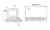
サーバ11は、受信したエラー画像と画像処理結果を表示装置13に表示し、警告音や警告灯等によって作業者に知らせる。図2と図3は、画像処理エラー発生時の表示装置13の表示例を示している。表示装置13に表示された「Error」は、画像処理エラーが発生したことを意味する。
The
図2に示すように、表示装置13にエラー画像として部品の画像が表示されている場合は、画像処理データを修正する必要がある可能性があるため、表示装置13に「修正する」と「修正しない」の項目を作業者がマウス、キーボード等の入力装置14の操作で選択できるように表示する。作業者が「修正する」を選択した場合は、作業者がエラー画像(画像処理エラー発生時の部品の画像)を見ながら入力装置14を操作して表示装置13の画面上で画像処理データを修正する。この際、サーバ11は、修正した画像処理データを用いて部品のエラー画像に対して画像処理を行い、修正した画像処理データの有効性を判定して、その判定結果を表示装置13に表示する。これにより、作業者は、修正した画像処理データの有効性を確認できるまで画像処理データの修正を繰り返し、画像処理データの有効性を確認できた段階で、サーバ11から修正した画像処理データを画像処理エラーが発生した実装機に送信して当該実装機の生産を再開させる。
As shown in FIG. 2, when an image of a part is displayed on the
尚、過去の画像処理に用いた部品画像を記憶装置に保存しておき、修正した画像処理データの有効性を確認する際に、修正した画像処理データを用いて過去の部品画像に対して画像処理のテストを行い、修正した画像処理データの有効性を確認するようにしても良い。このようにすれば、よりロバスト性の高い画像処理データを作成できる。 In addition, when the component image used for the past image processing is stored in the storage device and the validity of the corrected image processing data is confirmed, the image for the past component image is used using the corrected image processing data. A processing test may be performed to confirm the validity of the corrected image processing data. In this way, image processing data with higher robustness can be created.
生産を再開した実装機は、修正した画像処理データを用いて、吸着ノズルに吸着していた部品を再度、画像処理する。
一方、作業者が画像処理データを修正する必要がないと判断した場合は、「修正しない」を選択して、当該実装機の生産を再開させる。この場合は、実装機は、画像処理エラー発生時の画像処理データを引き続き使用して、吸着ノズルに吸着していた部品を再度、画像処理する。
The mounting machine that has resumed production uses the corrected image processing data to perform image processing again on the component that has been sucked by the suction nozzle.
On the other hand, when it is determined that the image processing data does not need to be corrected, “do not correct” is selected, and the production of the mounting machine is resumed. In this case, the mounting machine continues to use the image processing data at the time of occurrence of the image processing error, and performs image processing again on the component sucked by the suction nozzle.
一方、図3に示すように、表示装置13のエラー画像の表示領域に部品画像が表示されていない場合は、部品供給装置の部品切れ又は吸着ノズルの部品吸着ミスが発生した可能性があるため、表示装置13に「部品切れ確認」、「生産再開」、「生産停止」の項目を作業者が入力装置14の操作で選択できるように表示する。この場合、作業者が「部品切れ確認」を選択すると、サーバ11から画像処理エラーが発生した実装機に対して部品供給装置の部品切れの有無を確認して送信するように指示する。実装機が部品供給装置の部品切れを検出する機能を備えている場合は、部品供給装置の部品切れの有無の検出結果を送信する。部品供給装置の部品切れが検出されていない場合は、実装機は、部品供給装置の部品供給状態を基板マークカメラ等で撮像してその画像データをサーバ11に送信する。
On the other hand, as shown in FIG. 3, when no component image is displayed in the error image display area of the
尚、実装機が部品供給装置の部品切れを検出する機能を備えていない場合は、サーバ11から画像処理エラーが発生した実装機に対して部品供給装置の部品供給状態を基板マークカメラ等で撮像してその画像データを送信するように指示するようにしても良い。この場合も、実装機は、部品供給装置の部品供給状態を基板マークカメラ等で撮像してその画像データをサーバ11に送信する。
If the mounting machine does not have a function of detecting component breakage of the component supply device, the component supply state of the component supply device is imaged by a board mark camera or the like from the
サーバ11は、受信した部品供給装置の部品供給状態の画像データを表示装置13に表示する。これにより、作業者は、サーバ11の表示装置13に表示された部品供給装置の部品供給状態を見て、画像処理エラーの発生原因が吸着ノズルの部品吸着ミス、部品供給装置の故障、部品切れのいずれによるものかを確認することができる。
The
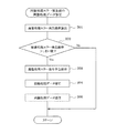
以上説明した本実施例1の画像処理エラー発生時の処理は、サーバ11によって図4の画像処理エラー復旧処理プログラムに従って実行される。図4の画像処理エラー復旧処理プログラムは、生産中に繰り返し実行される。本プログラムが起動されると、まず、ステップ101で、各実装機から送信されてくる画像処理情報を受信し、次のステップ102で、受信した画像処理情報を表示装置13に表示する。例えば、部品吸着有りで画像処理エラーが発生している場合は、図2に示すように、表示装置13の画面に、「Error」、部品のエラー画像、「修正する」、「修正しない」の項目が表示され、部品吸着無しで画像処理エラーが発生している場合は、図3に示すように、表示装置13の画面に、「Error」、「部品切れ確認」、「生産再開」、「生産停止」の項目が表示され、部品画像は表示されない。ここで、部品の有り/無しの判定は、例えば、画像処理対象エリアの輝度平均値の判定により行われる。
The processing when the image processing error occurs in the first embodiment described above is executed by the
この後、ステップ103に進み、画像処理結果が、画像処理成功、部品吸着有りの画像処理エラー(図2)、部品無しの画像処理エラー(図3)のいずれに該当するかを判定する。その結果、画像処理成功と判定されれば、そのまま本プログラムを終了する。 Thereafter, the process proceeds to step 103, and it is determined whether the image processing result corresponds to the image processing success, the image processing error with component adsorption (FIG. 2), or the image processing error without component (FIG. 3). As a result, if it is determined that the image processing is successful, the program is terminated as it is.
これに対し、上記ステップ103で、部品吸着有りの画像処理エラー(図2)と判定されれば、ステップ104に進み、作業者に画像処理データを修正するか否かを問い合わせ(具体的には作業者が表示装置13の画面上で「修正する」と「修正しない」のどちらを選択したかを判別し)、作業者が「修正する」を選択した場合は、ステップ105に進み、作業者がサーバ11の入力装置14を操作して表示装置13の画面上で画像処理データを修正するまで待機する。
On the other hand, if it is determined in
画像処理データの修正後に、ステップ106に進み、修正した画像処理データを画像処理エラーが発生した実装機に送信して、次のステップ107で、当該実装機に生産再開を指示する。この際、サーバ11は、修正した画像処理データを送信する前に、修正した画像処理データを用いて部品のエラー画像を画像処理して、修正した画像処理データの有効性を判定して、その判定結果を表示装置13に表示する。これにより、作業者は、修正した画像処理データの有効性を確認できるまで画像処理データの修正を繰り返し、画像処理データの有効性を確認できた段階で、サーバ11から修正した画像処理データを実装機に送信する。
After the correction of the image processing data, the process proceeds to step 106, where the corrected image processing data is transmitted to the mounting machine in which the image processing error has occurred, and in the
一方、上記ステップ104で、作業者が表示装置13の画面上で「修正しない」を選択した場合は、画像処理データを修正せずに、ステップ107に進み、画像処理エラーが発生した実装機に生産再開を指示する。
On the other hand, if the operator selects “Do not modify” on the screen of the
また、上記ステップ103で、部品無しの画像処理エラー(図3)と判定されれば、ステップ108に進み、作業者が表示装置13の画面上で「部品切れ確認」と「生産停止」のどちらを選択したか否かを判定し、作業者が「部品切れ確認」を選択した場合は、ステップ109に進み、サーバ11から画像処理エラーが発生した実装機に対して部品供給装置の部品切れの有無を確認して送信するように指示する。
If it is determined in
これに対し、上記ステップ108で、作業者が「生産停止」を選択したと判定されれば、ステップ110に進み、サーバ11から画像処理エラーが発生した実装機に対して生産停止を指示する。
On the other hand, if it is determined in
以上説明した本実施例1によれば、画像処理エラーの情報をサーバ11の表示装置13に表示させる機能と、作業者がサーバ11の表示装置13の表示を見て画像処理データを修正する機能と、修正した画像処理データをサーバ11から画像処理エラーが発生した実装機に送信して当該実装機の生産を再開させる機能とをサーバ11に搭載したので、各実装機の画像処理エラー発生状況の監視から画像処理データの修正及び生産再開までの作業をサーバ11側のみで一括して能率良く行うことができ、実装機のエラー発生から生産再開までの作業時間を短縮することができて、生産能率を向上できる。
According to the first embodiment described above, a function for displaying image processing error information on the
しかも、本実施例1では、作業者がサーバ11の表示装置13の画面上で「部品切れ確認」を選択したときに、サーバ11から画像処理エラーが発生した実装機に対して部品供給装置の部品切れの有無を確認して送信するように指示するようにしたので、画像処理エラーの発生原因が部品供給装置の部品切れであるか否かをサーバ11側で確認することができ、画像処理エラーの復旧作業を能率良く行うことができる。
In addition, in the first embodiment, when the worker selects “Parts out check” on the screen of the
この場合、作業者が画像処理エラー発生時に「部品切れ確認」を選択したときに、サーバ11から画像処理エラーが発生した実装機に対して部品供給装置の部品供給状態を基板マークカメラ等で撮像してその画像データを送信するように指示するようにすれば、作業者がサーバ11の表示装置13に表示された部品供給装置の部品供給状態を見て、画像処理エラーの発生原因が吸着ノズルの部品吸着ミス、部品供給装置の故障、部品切れのいずれによるものかを確認することができる。
In this case, when the operator selects “Parts Check” when an image processing error occurs, the component supply state of the component supply device is imaged by the board mark camera or the like from the
尚、本実施例1では、サーバ11の表示装置13のエラー画像の表示領域に部品画像が表示されていない場合(つまり部品無しの画像処理エラーが発生した場合)に、表示装置13に「部品切れ確認」を項目を表示し、作業者が「部品切れ確認」を選択したときのみ、実装機に部品切れの確認を指示するようにしたが、表示装置13のエラー画像の表示領域に部品画像が表示されていない場合(つまり部品無しの画像処理エラーが発生した場合)に、サーバ11が自動的に実装機に部品切れの確認を指示するようにしても良い。
In the first embodiment, when a component image is not displayed in the error image display area of the
本発明の実施例2では、サーバ11に内蔵した記憶装置に図5の画像処理エラー発生前の画像処理データ修正プログラムがインストールされている。これにより、サーバ11は、上記実施例1で説明した各機能に加え、各実装機で実行した画像処理の結果に基づいて画像処理エラー発生の可能性を予測してその予測結果をサーバ11の表示装置13に表示させる機能と、作業者が表示装置13に表示された画像処理エラー発生の予測結果を見て画像処理データを修正する機能と、修正した画像処理データを画像処理エラーの発生が予測された実装機に送信する機能とを備えた構成となっている。その他の事項は、上記実施例1と同じである。
In the second embodiment of the present invention, the image processing data correction program before the occurrence of the image processing error in FIG. 5 is installed in the storage device built in the
ここで、画像処理エラー発生の予測は、次のいずれかの方法で行えば良い。
[統計的手法による画像処理エラー発生の予測]
各実装機の画像処理結果のデータを蓄積して、統計的手法を用いて画像処理エラーの発生確率(又は安定度)を算出する。
Here, the prediction of the occurrence of an image processing error may be performed by one of the following methods.
[Prediction of image processing errors using statistical methods]
Data of image processing results of each mounting machine is accumulated, and an occurrence probability (or stability) of an image processing error is calculated using a statistical method.
例えば、位置決めの結果の分散値(ばらつき)が大きくなってきた場合は、画像処理が安定していないことを表すので、画像処理エラーの発生確率が高い。従って、予め、位置決めの結果の分散値(ばらつき)と画像処理エラーの発生確率との関係をテーブル等で設定しておき、位置決めの結果の分散値(ばらつき)を算出して、位置決めの結果の分散値(ばらつき)に応じた画像処理エラーの発生確率を算出しても良い。 For example, when the dispersion value (variation) as a result of the positioning becomes large, it indicates that the image processing is not stable, so that the probability of occurrence of an image processing error is high. Therefore, the relationship between the dispersion value (variation) of the positioning result and the occurrence probability of the image processing error is set in advance in a table or the like, the dispersion value (variation) of the positioning result is calculated, and the positioning result An occurrence probability of an image processing error corresponding to the dispersion value (variation) may be calculated.
また、良品検査等の測定値が合否判定のしきい値近傍の場合は、画像処理エラーの発生確率が高い。従って、予め良品検査等の測定値としきい値との差と画像処理エラーの発生確率との関係をテーブル等で設定しておき、良品検査等の測定値としきい値との差を算出してその差に応じた画像処理エラーの発生確率を算出しても良い。
[画像の類似度による画像処理エラー発生の予測]
画像処理データを作成する際に使用した画像又は過去の画像処理で用いた画像と新たに取得した画像とを比較して、両者の類似度が高いほど安定した画像処理を行うことができる。逆に、類似度が低いほど画像処理エラーの発生確率が高い。従って、画像処理データを作成する際に使用した画像又は過去の画像処理で用いた画像を記憶装置に記憶しておくと共に、予め、類似度と画像処理エラーの発生確率との関係をテーブル等で設定しておき、記憶装置に記憶されている画像と新たに取得した画像とを比較して、両者の類似度を算出して、類似度に応じた画像処理エラーの発生確率を算出しても良い。
尚、画像処理エラーの発生確率の算出は、サーバ11で行っても良いし、各実装機でそれぞれ行っても良い。
In addition, when a measurement value for non-defective product inspection or the like is in the vicinity of a threshold value for pass / fail judgment, the probability of occurrence of an image processing error is high. Therefore, the relationship between the difference between the measured value for the non-defective product inspection and the threshold value and the occurrence probability of the image processing error is set in advance in a table etc., and the difference between the measured value for the good product inspection etc. and the threshold value is calculated. An occurrence probability of an image processing error corresponding to the difference may be calculated.
[Prediction of image processing errors based on image similarity]
The image used when creating the image processing data or the image used in the past image processing is compared with the newly acquired image, and the higher the similarity between the two, the more stable image processing can be performed. Conversely, the lower the similarity, the higher the probability of an image processing error. Therefore, the image used when creating the image processing data or the image used in the past image processing is stored in the storage device, and the relationship between the similarity and the occurrence probability of the image processing error is previously stored in a table or the like. It is also possible to compare the image stored in the storage device with the newly acquired image, calculate the similarity between them, and calculate the probability of occurrence of an image processing error according to the similarity good.
The calculation of the occurrence probability of the image processing error may be performed by the
以上説明した本実施例2の画像処理エラー発生の予測は、サーバ11によって図5の画像処理エラー発生前の画像処理データ修正プログラムに従って実行される。図5の画像処理エラー発生前の画像処理データ修正プログラムは、生産中に繰り返し実行される。本プログラムが起動されると、まず、ステップ201で、画像処理エラーの発生確率を上述した方法で算出する。この後、ステップ202に進み、画像処理エラーの発生確率が所定のしきい値よりも高いか否かで、近いうちに画像処理エラーが発生するか否かを判定し、画像処理エラーの発生確率がしきい値以下であれば、近いうちに画像処理エラーが発生しないと予測して、そのまま本プログラムを終了する。
The prediction of the occurrence of the image processing error in the second embodiment described above is executed by the
これに対して、上記ステップ202で、画像処理エラーの発生確率がしきい値よりも高いと判定されれば、近いうちに画像処理エラーが発生する可能性が高いと判断して、ステップ203に進み、サーバ11の表示装置13に画像処理エラー発生を予告表示する。この予告表示と併せて、警告音や警告灯等によって作業者に知らせるようにしても良い。
On the other hand, if it is determined in
この後、ステップ204に進み、作業者がサーバ11の入力装置14を操作して表示装置13の画面上で画像処理データを修正するまで待機する。画像処理データの修正後に、ステップ205に進み、修正した画像処理データを、画像処理エラーの発生確率がしきい値よりも高いと判定された実装機に送信して本プログラムを終了する。
Thereafter, the process proceeds to step 204 and waits until the operator operates the
以上説明した本実施例2によれば、サーバ11又は各実装機は、各実装機で実行した画像処理の結果に基づいて画像処理エラー発生の可能性を予測してその予測結果をサーバ11の表示装置13に表示させる機能を備え、サーバ11は、作業者が表示装置13に表示された画像処理エラー発生の予測結果を見て画像処理データを修正する機能と、修正した画像処理データを画像処理エラーの発生が予測された実装機に送信する機能とを備えた構成としたので、いずれかの実装機で画像処理エラーが発生する前に、画像処理エラー発生の可能性を予測して、事前に画像処理データを修正して画像処理エラーの発生を予防することが可能となり、画像処理エラーによる生産停止を未然に防止することができて、生産性を更に高めることができる。
According to the second embodiment described above, the
上記実施例1,2では、複数台の実装機A1〜A5,B1〜B5とサーバ11とを接続するネットワークをスター型LANで構成したが、本発明の実施例2では、図6に示すように、複数台の実装機A1〜A5,B1〜B5とサーバ11とを接続するネットワークをバス型LANで構成している。或は、ネットワークをリング型LANで構成しても良い。その他の事項は、前記実施例1又は実施例2と同じである。
In the first and second embodiments, the network connecting the plurality of mounting machines A1 to A5 and B1 to B5 and the
その他、本発明は、上記各実施例1〜3に限定されず、例えば、サーバ11とネットワークで接続する実装機の台数を変更したり、サーバ11に搭載するCPUの数を変更したり、通信プロトコル等を変更しても良い等、要旨を逸脱しない範囲内で種々変更して実施できることは言うまでもない。
In addition, the present invention is not limited to the first to third embodiments. For example, the number of mounting machines connected to the
11…サーバ、12…スイッチングハブ、13…表示装置、14…入力装置、A1〜A5,B1〜B5…実装機
DESCRIPTION OF
Claims (4)
前記複数台の実装機にネットワークで接続されたサーバと、
前記サーバに接続された表示装置とを備え、
前記サーバは、各実装機で発生したエラーの情報を受信して前記表示装置に表示させる機能と、作業者が前記表示装置の表示を見て前記エラーを該サーバから復旧させる作業を実行できる機能とを備えた部品実装ラインの管理装置であって、
前記サーバが受信するエラーの情報は、各実装機で実行した画像処理で発生した画像処理エラーの情報であり、
前記サーバは、前記画像処理エラーの情報としてエラー画像と画像処理結果を前記表示装置に表示させる機能と、作業者が前記表示装置の表示を見て画像処理データを修正する機能と、修正した画像処理データを前記画像処理エラーが発生した実装機に送信して当該実装機の生産を再開させる機能と、前記エラー画像に部品が写っていない場合に前記画像処理エラーが発生した実装機に対して部品供給装置の部品切れの有無を確認して送信するように指示する機能とを備えていることを特徴とする部品実装ラインの管理装置。 In the component mounting line management system that arranges multiple mounting machines,
A server connected to the plurality of mounting machines via a network;
A display device connected to the server,
The server has a function of receiving information on an error that has occurred in each mounting machine and displaying the information on the display device, and a function of enabling an operator to recover the error from the server by viewing the display on the display device A component mounting line management device comprising:
The error information received by the server is information on an image processing error that has occurred in the image processing executed on each mounting machine.
The server includes a function for causing the display device to display an error image and an image processing result as information on the image processing error, a function for an operator to correct image processing data by viewing the display on the display device, and a corrected image. A function for transmitting processing data to the mounting machine in which the image processing error has occurred and restarting production of the mounting machine, and a mounting machine in which the image processing error has occurred when no part is shown in the error image A component mounting line management device, comprising: a function for instructing the component supply device to check whether or not a component has run out and to transmit the component.
前記複数台の実装機にネットワークで接続されたサーバと、A server connected to the plurality of mounting machines via a network;
前記サーバに接続された表示装置とを備え、A display device connected to the server,
前記サーバは、各実装機で発生したエラーの情報を受信して前記表示装置に表示させる機能と、作業者が前記表示装置の表示を見て前記エラーを該サーバから復旧させる作業を実行できる機能とを備えた部品実装ラインの管理装置であって、The server has a function of receiving information on an error that has occurred in each mounting machine and displaying the information on the display device, and a function of enabling an operator to recover the error from the server by viewing the display on the display device A component mounting line management device comprising:
前記サーバが受信するエラーの情報は、各実装機で実行した画像処理で発生した画像処理エラーの情報であり、The error information received by the server is information on an image processing error that has occurred in the image processing executed on each mounting machine.
前記サーバは、前記画像処理エラーの情報としてエラー画像と画像処理結果を前記表示装置に表示させる機能と、作業者が前記表示装置の表示を見て画像処理データを修正する機能と、修正した画像処理データを前記画像処理エラーが発生した実装機に送信して当該実装機の生産を再開させる機能と、前記エラー画像に部品が写っていない場合に前記画像処理エラーが発生した実装機に対して部品供給装置の部品供給状態をカメラで撮像してその画像データを送信するように指示する機能を備えていることを特徴とする部品実装ラインの管理装置。The server includes a function for causing the display device to display an error image and an image processing result as information on the image processing error, a function for an operator to correct image processing data by viewing the display on the display device, and a corrected image. A function for transmitting processing data to the mounting machine in which the image processing error has occurred and restarting production of the mounting machine, and a mounting machine in which the image processing error has occurred when no part is shown in the error image A component mounting line management apparatus comprising a function of instructing to capture a component supply state of a component supply apparatus with a camera and to transmit the image data.
前記複数台の実装機に接続されたサーバと、
前記サーバに接続された表示装置とを備え、
前記サーバ又は各実装機は、各実装機で実行した画像処理の結果に基づいて画像処理エラー発生の可能性を予測してその予測結果を前記表示装置に表示させる機能を備え、
前記サーバは、作業者が前記表示装置に表示された前記画像処理エラー発生の予測結果を見て画像処理データを修正する機能と、修正した画像処理データを前記画像処理エラーの発生が予測された実装機に送信する機能とを備えていることを特徴とする部品実装ラインの管理装置。 In the component mounting line management system that arranges multiple mounting machines,
A server connected to the plurality of mounting machines;
A display device connected to the server,
The server or each mounting machine has a function of predicting the possibility of an image processing error occurrence based on the result of image processing executed by each mounting machine and displaying the prediction result on the display device,
The server has a function of correcting an image processing data by looking at a prediction result of the image processing error occurrence displayed on the display device by an operator, and the occurrence of the image processing error is predicted from the corrected image processing data. A component mounting line management device comprising a function of transmitting to a mounting machine.
Priority Applications (1)
| Application Number | Priority Date | Filing Date | Title |
|---|---|---|---|
| JP2010234181A JP5594886B2 (en) | 2010-10-19 | 2010-10-19 | Component mounting line management device |
Applications Claiming Priority (1)
| Application Number | Priority Date | Filing Date | Title |
|---|---|---|---|
| JP2010234181A JP5594886B2 (en) | 2010-10-19 | 2010-10-19 | Component mounting line management device |
Publications (2)
| Publication Number | Publication Date |
|---|---|
| JP2012089634A JP2012089634A (en) | 2012-05-10 |
| JP5594886B2 true JP5594886B2 (en) | 2014-09-24 |
Family
ID=46260955
Family Applications (1)
| Application Number | Title | Priority Date | Filing Date |
|---|---|---|---|
| JP2010234181A Active JP5594886B2 (en) | 2010-10-19 | 2010-10-19 | Component mounting line management device |
Country Status (1)
| Country | Link |
|---|---|
| JP (1) | JP5594886B2 (en) |
Families Citing this family (15)
| Publication number | Priority date | Publication date | Assignee | Title |
|---|---|---|---|---|
| JP6132845B2 (en) | 2012-09-28 | 2017-05-24 | 富士機械製造株式会社 | Component mounting line and component image processing data creation method in component mounting line |
| JP6411028B2 (en) * | 2014-01-17 | 2018-10-24 | 株式会社Fuji | Management device |
| JP6264072B2 (en) * | 2014-02-10 | 2018-01-24 | オムロン株式会社 | Quality control device and control method thereof |
| CN107072142B (en) | 2016-02-10 | 2020-11-13 | 松下知识产权经营株式会社 | Component mounting system and component mounting method |
| JP6586642B2 (en) * | 2016-02-10 | 2019-10-09 | パナソニックIpマネジメント株式会社 | Component mounting system and component mounting method |
| JP6586641B2 (en) * | 2016-02-10 | 2019-10-09 | パナソニックIpマネジメント株式会社 | Component mounting system and component mounting method |
| JP6484818B2 (en) * | 2016-02-10 | 2019-03-20 | パナソニックIpマネジメント株式会社 | Component mounting system and component mounting method |
| JP6484817B2 (en) * | 2016-02-10 | 2019-03-20 | パナソニックIpマネジメント株式会社 | Component mounting system and component mounting method |
| JP6484819B2 (en) * | 2016-02-10 | 2019-03-20 | パナソニックIpマネジメント株式会社 | Component mounting system and component mounting method |
| JP7179211B2 (en) * | 2017-01-10 | 2022-11-28 | 株式会社Fuji | Implementation system and error handling method |
| CN110168458B (en) * | 2017-01-10 | 2023-03-14 | 株式会社富士 | Management device, installation-related device, and installation system |
| JP7088809B2 (en) * | 2018-11-06 | 2022-06-21 | ヤマハ発動機株式会社 | Work work device, work work system, and control method of work work device |
| JP7285396B2 (en) * | 2019-07-05 | 2023-06-02 | パナソニックIpマネジメント株式会社 | remote control system |
| JP2021093532A (en) * | 2021-01-14 | 2021-06-17 | パナソニックIpマネジメント株式会社 | Error handling method |
| JP7281619B2 (en) * | 2021-01-14 | 2023-05-26 | パナソニックIpマネジメント株式会社 | Error handling method |
Family Cites Families (3)
| Publication number | Priority date | Publication date | Assignee | Title |
|---|---|---|---|---|
| JPH06209198A (en) * | 1993-01-12 | 1994-07-26 | Matsushita Electric Ind Co Ltd | Component recognition method |
| JP2003224400A (en) * | 2002-01-30 | 2003-08-08 | Matsushita Electric Ind Co Ltd | Method, system, and program for modifying recognized data |
| JP4913720B2 (en) * | 2007-12-28 | 2012-04-11 | 株式会社日立ハイテクインスツルメンツ | Electronic component mounting method for electronic component mounting apparatus |
-
2010
- 2010-10-19 JP JP2010234181A patent/JP5594886B2/en active Active
Also Published As
| Publication number | Publication date |
|---|---|
| JP2012089634A (en) | 2012-05-10 |
Similar Documents
| Publication | Publication Date | Title |
|---|---|---|
| JP5594886B2 (en) | Component mounting line management device | |
| US11550313B2 (en) | Equipment element maintenance analysis system and equipment element maintenance analysis method | |
| US20100042820A1 (en) | Self-restarting network devices | |
| CN111865688B (en) | Gateway monitoring method and device, electronic equipment and storage medium | |
| EP3499330A1 (en) | Management system, management device, management method, and program | |
| JP2018056447A (en) | Inspection apparatus and component mounting system, and component mounting method | |
| JP3772906B1 (en) | Information processing apparatus, information processing method, program, and computer-readable recording medium recording the program | |
| JP5980944B2 (en) | Production monitoring system and production monitoring method for component mounting line | |
| JP2019062163A (en) | Malfunction detection system and malfunction detection method of component mounting line | |
| JP2006339244A (en) | Mounting line | |
| JP6259565B2 (en) | Mounting management device, inspection management device, mounting system, mounting management method and program thereof, and inspection management method and program thereof | |
| JP2014165440A (en) | Production management device | |
| JP6120863B2 (en) | Operational status monitoring system for component mounters | |
| US11714404B2 (en) | Board production management device and board production management method | |
| JP7065294B2 (en) | Manufacturing system and manufacturing method | |
| JP4301873B2 (en) | Substrate work machine support device | |
| KR20160001444A (en) | System for setting reference information monitoring and forecasting system in SMT production line | |
| CN110050443B (en) | Substrate processing system | |
| JP6335246B2 (en) | Inspection management apparatus and inspection management method | |
| US11157344B2 (en) | Failure information sharing system | |
| JP7352774B2 (en) | Component mounting equipment, component mounting system, and mounting board manufacturing method | |
| WO2013051145A1 (en) | Computer system, management device, management method, and program | |
| JP2020129591A (en) | Component mounting system and mounting board manufacturing method | |
| JP7394293B2 (en) | Nozzle maintenance analysis system and nozzle maintenance analysis method | |
| US20230360005A1 (en) | Work device analysis system and work device analysis method, and data collection device |
Legal Events
| Date | Code | Title | Description |
|---|---|---|---|
| A621 | Written request for application examination |
Free format text: JAPANESE INTERMEDIATE CODE: A621 Effective date: 20130827 |
|
| A131 | Notification of reasons for refusal |
Free format text: JAPANESE INTERMEDIATE CODE: A131 Effective date: 20140319 |
|
| A977 | Report on retrieval |
Free format text: JAPANESE INTERMEDIATE CODE: A971007 Effective date: 20140320 |
|
| A521 | Request for written amendment filed |
Free format text: JAPANESE INTERMEDIATE CODE: A523 Effective date: 20140508 |
|
| TRDD | Decision of grant or rejection written | ||
| A01 | Written decision to grant a patent or to grant a registration (utility model) |
Free format text: JAPANESE INTERMEDIATE CODE: A01 Effective date: 20140804 |
|
| A61 | First payment of annual fees (during grant procedure) |
Free format text: JAPANESE INTERMEDIATE CODE: A61 Effective date: 20140804 |
|
| R150 | Certificate of patent or registration of utility model |
Ref document number: 5594886 Country of ref document: JP Free format text: JAPANESE INTERMEDIATE CODE: R150 |
|
| R250 | Receipt of annual fees |
Free format text: JAPANESE INTERMEDIATE CODE: R250 |
|
| R250 | Receipt of annual fees |
Free format text: JAPANESE INTERMEDIATE CODE: R250 |
|
| S533 | Written request for registration of change of name |
Free format text: JAPANESE INTERMEDIATE CODE: R313533 |
|
| R350 | Written notification of registration of transfer |
Free format text: JAPANESE INTERMEDIATE CODE: R350 |
|
| R250 | Receipt of annual fees |
Free format text: JAPANESE INTERMEDIATE CODE: R250 |
|
| R250 | Receipt of annual fees |
Free format text: JAPANESE INTERMEDIATE CODE: R250 |
|
| R250 | Receipt of annual fees |
Free format text: JAPANESE INTERMEDIATE CODE: R250 |
|
| R250 | Receipt of annual fees |
Free format text: JAPANESE INTERMEDIATE CODE: R250 |
|
| R250 | Receipt of annual fees |
Free format text: JAPANESE INTERMEDIATE CODE: R250 |