JP7065294B2 - Manufacturing system and manufacturing method - Google Patents
Manufacturing system and manufacturing method Download PDFInfo
- Publication number
- JP7065294B2 JP7065294B2 JP2017196512A JP2017196512A JP7065294B2 JP 7065294 B2 JP7065294 B2 JP 7065294B2 JP 2017196512 A JP2017196512 A JP 2017196512A JP 2017196512 A JP2017196512 A JP 2017196512A JP 7065294 B2 JP7065294 B2 JP 7065294B2
- Authority
- JP
- Japan
- Prior art keywords
- manufacturing
- remote
- error
- remote terminal
- manufacturing equipment
- Prior art date
- Legal status (The legal status is an assumption and is not a legal conclusion. Google has not performed a legal analysis and makes no representation as to the accuracy of the status listed.)
- Active
Links
Images


Classifications
-
- G—PHYSICS
- G05—CONTROLLING; REGULATING
- G05B—CONTROL OR REGULATING SYSTEMS IN GENERAL; FUNCTIONAL ELEMENTS OF SUCH SYSTEMS; MONITORING OR TESTING ARRANGEMENTS FOR SUCH SYSTEMS OR ELEMENTS
- G05B19/00—Programme-control systems
- G05B19/02—Programme-control systems electric
- G05B19/418—Total factory control, i.e. centrally controlling a plurality of machines, e.g. direct or distributed numerical control [DNC], flexible manufacturing systems [FMS], integrated manufacturing systems [IMS], computer integrated manufacturing [CIM]
- G05B19/4188—Total factory control, i.e. centrally controlling a plurality of machines, e.g. direct or distributed numerical control [DNC], flexible manufacturing systems [FMS], integrated manufacturing systems [IMS], computer integrated manufacturing [CIM] characterised by CIM planning or realisation
-
- H—ELECTRICITY
- H05—ELECTRIC TECHNIQUES NOT OTHERWISE PROVIDED FOR
- H05K—PRINTED CIRCUITS; CASINGS OR CONSTRUCTIONAL DETAILS OF ELECTRIC APPARATUS; MANUFACTURE OF ASSEMBLAGES OF ELECTRICAL COMPONENTS
- H05K13/00—Apparatus or processes specially adapted for manufacturing or adjusting assemblages of electric components
- H05K13/08—Monitoring manufacture of assemblages
-
- G—PHYSICS
- G05—CONTROLLING; REGULATING
- G05B—CONTROL OR REGULATING SYSTEMS IN GENERAL; FUNCTIONAL ELEMENTS OF SUCH SYSTEMS; MONITORING OR TESTING ARRANGEMENTS FOR SUCH SYSTEMS OR ELEMENTS
- G05B19/00—Programme-control systems
- G05B19/02—Programme-control systems electric
- G05B19/418—Total factory control, i.e. centrally controlling a plurality of machines, e.g. direct or distributed numerical control [DNC], flexible manufacturing systems [FMS], integrated manufacturing systems [IMS], computer integrated manufacturing [CIM]
- G05B19/4184—Total factory control, i.e. centrally controlling a plurality of machines, e.g. direct or distributed numerical control [DNC], flexible manufacturing systems [FMS], integrated manufacturing systems [IMS], computer integrated manufacturing [CIM] characterised by fault tolerance, reliability of production system
-
- H—ELECTRICITY
- H05—ELECTRIC TECHNIQUES NOT OTHERWISE PROVIDED FOR
- H05K—PRINTED CIRCUITS; CASINGS OR CONSTRUCTIONAL DETAILS OF ELECTRIC APPARATUS; MANUFACTURE OF ASSEMBLAGES OF ELECTRICAL COMPONENTS
- H05K13/00—Apparatus or processes specially adapted for manufacturing or adjusting assemblages of electric components
- H05K13/08—Monitoring manufacture of assemblages
- H05K13/083—Quality monitoring using results from monitoring devices, e.g. feedback loops
-
- H—ELECTRICITY
- H05—ELECTRIC TECHNIQUES NOT OTHERWISE PROVIDED FOR
- H05K—PRINTED CIRCUITS; CASINGS OR CONSTRUCTIONAL DETAILS OF ELECTRIC APPARATUS; MANUFACTURE OF ASSEMBLAGES OF ELECTRICAL COMPONENTS
- H05K13/00—Apparatus or processes specially adapted for manufacturing or adjusting assemblages of electric components
- H05K13/08—Monitoring manufacture of assemblages
- H05K13/0882—Control systems for mounting machines or assembly lines, e.g. centralized control, remote links, programming of apparatus and processes as such
-
- G—PHYSICS
- G05—CONTROLLING; REGULATING
- G05B—CONTROL OR REGULATING SYSTEMS IN GENERAL; FUNCTIONAL ELEMENTS OF SUCH SYSTEMS; MONITORING OR TESTING ARRANGEMENTS FOR SUCH SYSTEMS OR ELEMENTS
- G05B2219/00—Program-control systems
- G05B2219/30—Nc systems
- G05B2219/32—Operator till task planning
- G05B2219/32222—Fault, defect detection of origin of fault, defect of product
-
- G—PHYSICS
- G05—CONTROLLING; REGULATING
- G05B—CONTROL OR REGULATING SYSTEMS IN GENERAL; FUNCTIONAL ELEMENTS OF SUCH SYSTEMS; MONITORING OR TESTING ARRANGEMENTS FOR SUCH SYSTEMS OR ELEMENTS
- G05B2219/00—Program-control systems
- G05B2219/30—Nc systems
- G05B2219/45—Nc applications
- G05B2219/45029—Mount and solder parts on board
-
- G—PHYSICS
- G05—CONTROLLING; REGULATING
- G05B—CONTROL OR REGULATING SYSTEMS IN GENERAL; FUNCTIONAL ELEMENTS OF SUCH SYSTEMS; MONITORING OR TESTING ARRANGEMENTS FOR SUCH SYSTEMS OR ELEMENTS
- G05B2219/00—Program-control systems
- G05B2219/30—Nc systems
- G05B2219/45—Nc applications
- G05B2219/45031—Manufacturing semiconductor wafers
-
- Y—GENERAL TAGGING OF NEW TECHNOLOGICAL DEVELOPMENTS; GENERAL TAGGING OF CROSS-SECTIONAL TECHNOLOGIES SPANNING OVER SEVERAL SECTIONS OF THE IPC; TECHNICAL SUBJECTS COVERED BY FORMER USPC CROSS-REFERENCE ART COLLECTIONS [XRACs] AND DIGESTS
- Y02—TECHNOLOGIES OR APPLICATIONS FOR MITIGATION OR ADAPTATION AGAINST CLIMATE CHANGE
- Y02P—CLIMATE CHANGE MITIGATION TECHNOLOGIES IN THE PRODUCTION OR PROCESSING OF GOODS
- Y02P90/00—Enabling technologies with a potential contribution to greenhouse gas [GHG] emissions mitigation
- Y02P90/02—Total factory control, e.g. smart factories, flexible manufacturing systems [FMS] or integrated manufacturing systems [IMS]
Description
本発明は、リモート操作が可能な複数の製造設備を備える製造システムおよび製造方法に関するものである。 The present invention relates to a manufacturing system and a manufacturing method including a plurality of manufacturing facilities capable of remote operation.
はんだ印刷機、印刷後検査機、部品実装機、実装後検査機など複数の製造設備を連結して構成される部品実装ラインは、基板に部品を実装した実装基板を製造する製造システムである。このような部品実装ラインでは、部品補給、装置エラー対応などの各種現場作業を行うために製造設備に設けられた操作パネルを現場作業者が直接操作する現場操作の他、製造設備以外の外部のPC等の管理装置から管理者が製造設備を操作するリモート操作ができる部品実装システムが提案されている(例えば、特許文献1)。 A component mounting line composed of a plurality of manufacturing facilities such as a solder printing machine, a post-printing inspection machine, a component mounting machine, and a post-mounting inspection machine is a manufacturing system for manufacturing a mounting board in which components are mounted on a board. In such a component mounting line, in addition to on-site operations in which field workers directly operate the operation panel provided in the manufacturing equipment to perform various on-site work such as parts replenishment and equipment error handling, external operations other than the manufacturing equipment. A component mounting system has been proposed in which a manager can remotely operate a manufacturing facility from a management device such as a PC (for example, Patent Document 1).
しかしながら、特許文献1を含む従来の部品実装システムでは、特定の設備でエラーが発生した際は現場作業者が電話連絡などで管理者に連絡し、管理者が連絡に応じて対象の設備を特定してリモート操作を実施するようになっており、エラー対応を円滑に実行するためには更なる改善の余地があった。
However, in the conventional component mounting system including
そこで本発明は、エラーを検出した際のリモート操作を円滑に実行することができる製造システムおよび製造方法を提供することを目的とする。 Therefore, an object of the present invention is to provide a manufacturing system and a manufacturing method capable of smoothly executing a remote operation when an error is detected.
本発明の製造システムは、直列に連結されてラインを構成し、前記ラインの上流側から下流側に向けて搬送される基板に対して順に作業を実行する複数の製造設備と、前記複数の製造設備の少なくともいずれか1つのリモート操作を行うためのリモート端末と、前記リモート端末によるリモート操作の権限を制御するリモート権限制御部と、前記複数の製造設備のうちの第1の製造設備でエラーを検出した場合に、前記第1の製造設備よりも上流側に位置する前記エラーの原因となった第2の製造設備を特定するエラー原因設備特定部と、を備え、前記リモート権限制御部は、前記リモート端末に対して、前記第2の製造設備のリモート操作の権限を与え、前記リモート端末は、表示部を有し、前記リモート権限制御部は、前記第1の製造設備で検出されたエラーに関する情報を前記表示部に表示させ、前記リモート権限制御部は、前記表示部に表示させたエラーのいずれかが前記リモート端末によって選択されると、選択された前記エラーの原因となった第2の製造設備のリモート操作の権限を前記リモート端末に与える。
また、本発明の製造システムは、複数の製造設備と、前記複数の製造設備の少なくともいずれか1つのリモート操作を行うためのリモート端末と、前記リモート端末によるリモート操作の権限を制御するリモート権限制御部と、を備え、前記リモート権限制御部は、前記複数の製造設備のうちの第1の製造設備でエラーを検出した場合に、前記リモート端末に対して、前記エラーの原因となった前記第1の製造設備以外の第2の製造設備のリモート操作の権限を与え、前記リモート端末は、表示部を有し、前記リモート権限制御部は、前記第1の製造設備で検出されたエラーに関する情報を前記表示部に表示させ、前記リモート権限制御部は、前記表示部に表示させたエラーのいずれかが前記リモート端末によって選択されると、選択された前記エラーの原因となった第2の製造設備のリモート操作の権限を前記リモート端末に与える。
The manufacturing system of the present invention comprises a plurality of manufacturing equipment that are connected in series to form a line and sequentially execute work on a substrate conveyed from the upstream side to the downstream side of the line, and the plurality of manufacturing. An error occurs in the remote terminal for performing remote operation of at least one of the equipment, the remote authority control unit for controlling the authority of remote operation by the remote terminal, and the first manufacturing equipment among the plurality of manufacturing equipment. The remote authority control unit includes an error-causing equipment specifying unit that identifies the second manufacturing equipment that caused the error, which is located upstream of the first manufacturing equipment when detected. The remote terminal is authorized to remotely operate the second manufacturing equipment, the remote terminal has a display unit, and the remote authority control unit has an error detected in the first manufacturing equipment. The remote authority control unit causes the selected error when any of the errors displayed on the display unit is selected by the remote terminal. The authority for remote operation of the manufacturing equipment of the above is given to the remote terminal .
Further, the manufacturing system of the present invention includes a plurality of manufacturing equipment, a remote terminal for performing remote operation of at least one of the plurality of manufacturing equipment, and remote authority control for controlling the authority of remote operation by the remote terminal. When the remote authority control unit detects an error in the first manufacturing equipment among the plurality of manufacturing equipment, the remote authority control unit causes the error with respect to the remote terminal. The remote terminal has a display unit, and the remote authority control unit gives authority for remote operation of a second manufacturing equipment other than the first manufacturing equipment, and the remote authority control unit provides information on an error detected in the first manufacturing equipment. Is displayed on the display unit, and the remote authority control unit causes the selected error when any of the errors displayed on the display unit is selected by the remote terminal. The authority to remotely operate the equipment is given to the remote terminal.
本発明の製造方法は、直列に連結されてラインを構成し、前記ラインの上流側から下流側に向けて搬送される基板に対して順に作業を実行する複数の製造設備と、前記複数の製造設備の少なくともいずれか1つのリモート操作を行うためのリモート端末と、を備える製造システムにおける製造方法であって、前記複数の製造設備において、エラーの発生を監視し、前記複数の製造設備のうちの第1の製造設備でエラーを検出した場合に、前記第1の製造設備よりも上流側に位置する前記エラーの原因となった第2の製造設備を特定し、前記リモート端末に対して、前記第2の製造設備のリモート操作の権限を与え、前記リモート端末は、表示部を有し、前記複数の製造設備のうちの第1の製造設備でエラーを検出した場合に、前記第1の製造設備で検出されたエラーに関する情報を前記表示部に表示させ、前記リモート端末によって、前記表示部に表示されたエラーのいずれかを選択し、選択された前記エラーの原因となった第2の製造設備のリモート操作の権限を前記リモート端末に与える。
また、本発明の製造方法は、複数の製造設備と、前記複数の製造設備の少なくともいずれか1つのリモート操作を行うためのリモート端末と、を備える製造システムにおける製造方法であって、前記複数の製造設備において、エラーの発生を監視し、前記複数の製造設備のうちの第1の製造設備でエラーを検出した場合に、前記リモート端末に対して、前記エラーの原因となった前記第1の製造設備以外の第2の製造設備のリモート操作の権限を与え、前記リモート端末は、表示部を有し、前記複数の製造設備のうちの第1の製造設備でエラーを検出した場合に、前記第1の製造設備で検出されたエラーに関する情報を前記表示部に表示させ、前記リモート端末によって、前記表示部に表示されたエラーのいずれかを選択し、選択された前記エラーの原因となった第2の製造設備のリモート操作の権限を前記リモート端末に与える。
The manufacturing method of the present invention comprises a plurality of manufacturing equipment that are connected in series to form a line and sequentially execute work on a substrate conveyed from the upstream side to the downstream side of the line, and the plurality of manufacturing facilities. A manufacturing method in a manufacturing system comprising a remote terminal for performing remote operation of at least one of the equipment, wherein error occurrence is monitored in the plurality of manufacturing equipment, and the plurality of manufacturing equipment is used. When an error is detected in the first manufacturing equipment, the second manufacturing equipment that is located upstream of the first manufacturing equipment and causes the error is identified, and the remote terminal is described as described above. Authorizing the remote operation of the second manufacturing equipment, the remote terminal has a display unit, and when an error is detected in the first manufacturing equipment among the plurality of manufacturing equipment, the first manufacturing A second manufacturing that causes the display to display information about the error detected in the equipment, selects one of the errors displayed on the display by the remote terminal, and causes the selected error. The authority to remotely operate the equipment is given to the remote terminal .
Further, the manufacturing method of the present invention is a manufacturing method in a manufacturing system including a plurality of manufacturing equipment and a remote terminal for performing remote operation of at least one of the plurality of manufacturing equipment, and the plurality of manufacturing methods. In the manufacturing equipment, when the occurrence of an error is monitored and an error is detected in the first manufacturing equipment among the plurality of manufacturing equipment, the first manufacturing equipment that causes the error is transmitted to the remote terminal. The remote terminal has a display unit, and when an error is detected in the first manufacturing equipment among the plurality of manufacturing equipment, the remote terminal is authorized to remotely operate the second manufacturing equipment other than the manufacturing equipment. Information on the error detected in the first manufacturing equipment is displayed on the display unit, and one of the errors displayed on the display unit is selected by the remote terminal, which causes the selected error. The authority for remote operation of the second manufacturing equipment is given to the remote terminal.
本発明によれば、エラーを検出した際のリモート操作を円滑に実行することができる。 According to the present invention, remote operation when an error is detected can be smoothly executed.
以下に図面を用いて、本発明の一実施の形態を詳細に説明する。以下で述べる構成、形状等は説明のための例示であって、部品実装システムの仕様に応じ、適宜変更が可能である。以下では、全ての図面において対応する要素には同一符号を付し、重複する説明を省略する。 Hereinafter, embodiments of the present invention will be described in detail with reference to the drawings. The configuration, shape, etc. described below are examples for explanation, and can be changed as appropriate according to the specifications of the component mounting system. In the following, the corresponding elements are designated by the same reference numerals in all the drawings, and duplicate description will be omitted.
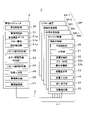
まず図1を参照して、部品実装システム1の構成を説明する。部品実装システム1は、部品実装ラインL1を通信ネットワーク2によって接続し、全体が管理コンピュータ3によって管理される構成の製造システムである。部品実装ラインL1は、基板搬送方向の上流側から下流側に向けて、基板供給装置M1、はんだ印刷機M2、印刷後検査機M3、基板受渡装置M4、部品実装機M5~M8、基板受渡装置M9、実装後検査機M10、リフロー装置M11及び基板回収装置M12を直列に連結して構成されている。
First, the configuration of the
図1において、基板供給装置M1は、実装対象の基板を供給する機能を有している。基板受渡装置M4,M9は、基板を上流側の装置から受け取って下流側の装置に受け渡す機能を有している。基板回収装置M12は、部品が実装された基板を回収する機能を有している。このように、基板供給装置M1、基板受渡装置M4,M9、及び基板回収装置M12は、部品実装ラインL1内を搬送される基板に対する部品実装用作業は実行せずに、以下に説明する製造設備MPに基板を供給し、受け渡しし、回収する。 In FIG. 1, the board supply device M1 has a function of supplying a board to be mounted. The board delivery devices M4 and M9 have a function of receiving the board from the device on the upstream side and delivering it to the device on the downstream side. The board recovery device M12 has a function of collecting a board on which components are mounted. As described above, the board supply device M1, the board delivery device M4, and the board recovery device M12 do not execute the component mounting work on the board transported in the component mounting line L1, but the manufacturing equipment described below. The board is supplied to the MP, delivered, and collected.
はんだ印刷機M2は、はんだ印刷作業部(作業部)によって実装対象の基板にはんだを印刷するはんだ印刷作業(部品実装用作業)を実行する製造設備MPである。印刷後検査機M3は、はんだ検査カメラを含むはんだ印刷後検査作業部(作業部)によって基板に印刷されたはんだの印刷状態を検査するはんだ印刷後検査作業(部品実装用作業)を実行する製造設備MPである。部品実装機M5~M8は、それぞれ部品実装作業部(作業部)によって基板に部品を実装する部品実装作業(部品実装用作業)を実行する製造設備MPである。 The solder printing machine M2 is a manufacturing equipment MP that executes solder printing work (parts mounting work) for printing solder on a board to be mounted by a solder printing work unit (working unit). The post-printing inspection machine M3 is manufactured to execute post-soldering inspection work (part mounting work) for inspecting the printing state of the solder printed on the board by the post-soldering inspection work unit (working unit) including the solder inspection camera. Equipment MP. The component mounting machines M5 to M8 are manufacturing equipment MPs that execute component mounting work (component mounting work) for mounting components on a board by the component mounting work unit (work unit), respectively.
実装後検査機M10は、部品検査カメラを含む部品実装後検査作業部(作業部)によって基板に実装された部品の実装状態を検査する部品実装後検査作業(部品実装用作業)を実行する製造設備MPである。リフロー装置M11は、装置内に搬入された基板を基板加熱部(作業部)によって加熱して、基板上のはんだを硬化させ、基板の電極部と部品とを接合する基板加熱作業(部品実装用作業)を実行する製造設備MPである。 The post-mounting inspection machine M10 is manufactured to execute post-mounting inspection work (part mounting work) for inspecting the mounting state of parts mounted on a board by a post-mounting inspection work unit (working unit) including a parts inspection camera. Equipment MP. The reflow apparatus M11 heats the substrate carried into the apparatus by the substrate heating unit (working unit), cures the solder on the substrate, and joins the electrode portion of the substrate and the component to the substrate heating operation (for component mounting). It is a manufacturing equipment MP that executes work).
このように、部品実装システム1では、部品実装ラインL1内を搬送される基板に対し、製造設備MPによって順に、はんだ印刷作業、はんだ印刷後検査作業、部品実装作業、部品実装後検査作業、基板加熱作業が実行されて、基板にはんだを介して部品を実装した実装基板が製造される。なお、部品実装ラインL1は上記の構成に限定されることなく、部品実装機M5~M8が1台であっても5台以上であってもよい。また、部品実装システム1は、複数の部品実装ラインL1を同一の管理コンピュータ3で制御する構成であってもよい。
As described above, in the
次に図2を参照して、部品実装システム1の制御系の構成について説明する。ここでは部品実装システム1のうち、部品実装用作業を実行する製造設備MPと、管理コンピュータ3の制御系について説明する。製造設備MPである、はんだ印刷機M2、印刷後検査機M3、部品実装機M5~M8、実装後検査機M10、リフロー装置M11は、部品実装用作業を実行する作業部21が、それぞれはんだ印刷作業部、はんだ印刷後検査作業部、部品実装作業部、部品実装後検査作業部、基板加熱部である他は、同様の制御系の構成をしている。以下、製造設備MPを代表して部品実装機M5を用いて説明する。
Next, the configuration of the control system of the
製造設備MP(部品実装機M5)は、作業制御部20、作業部21、装置記憶部22、装置監視部23、装置入力部24、装置表示部25、装置通信部26を備えている。作業制御部20は、装置記憶部22が記憶する部品実装用データに基づいて作業部21を制御することにより、製造設備MPによる部品実装用作業を制御する。すなわち作業制御部20は、はんだ印刷機M2でははんだ印刷作業、印刷後検査機M3でははんだ印刷後検査作業、部品実装機M5~M8では部品実装作業、実装後検査機M10では部品実装後検査作業、リフロー装置M11では基板加熱作業を制御する。
The manufacturing equipment MP (parts mounting machine M5) includes a
装置記憶部22は、部品実装用データの他、エラー情報22a、操作権情報22bを記憶する。操作権情報22bには、その製造設備MPが現場操作権を保持しているか、管理コンピュータ3がリモート操作権RRを保持しているかの情報が記憶されている。現場操作権とは、その製造設備MPにおいて現場作業者が現場操作を行うことが可能となる権限である。リモート操作権とは、主に製造設備MPから離れた管理コンピュータ3(リモート端末)において作業を行うリモート作業者が、管理コンピュータ3によって通信ネットワーク2を介して製造設備MPを操作することができるリモート操作の権限である。
The
図2において、装置監視部23は、製造設備MPの作業部21の動作状態、検査結果、各種センサの出力信号などを監視し、装置エラーを検出するとエラー情報22aに記憶させるとともに、装置通信部26を介して管理コンピュータ3に送信する。例えば、部品実装機M5の装置エラーには、テープフィーダが供給する部品が消費され尽くされる部品切れエラー、搬送された基板が所定の基板停止位置からずれて停止する基板位置ずれエラー、吸着ノズルが保持していることが期待される部品が検出されない部品認識エラーなどがある。
In FIG. 2, the
また、印刷後検査機M3の装置エラーには印刷されたはんだが所定の形状規格外であるはんだ検査エラーなど、実装後検査機M10の装置エラーには部品が基板の所定の位置にない実装検査エラーなどがある。 Further, in the device error of the post-printing inspection machine M3, the printed solder is out of the predetermined shape standard, such as a solder inspection error. There are errors and so on.
装置入力部24は、キーボード、タッチパネル、マウスなどの入力装置であり、現場作業者による操作コマンドやデータ入力時に用いられる。装置表示部25は液晶パネルなどの表示装置であり、装置入力部24による現場操作のための操作画面などの各種画面の表示を行う。装置通信部26は通信インターフェースであり、通信ネットワーク2(ネットワーク)を介して他の製造設備MPや管理コンピュータ3との間で信号の授受を行う。
The
図2において、管理コンピュータ3は、管理制御部30、管理記憶部31、リモート操作制御部32、エラー原因設備特定部33、リモート権限制御部34、管理入力部35、管理表示部36、管理通信部37を備えている。管理入力部35は、キーボード、タッチパネル、マウスなどの入力装置であり、操作コマンドやデータ入力時、製造設備MPのリモート操作などに用いられる。管理表示部36は液晶パネルなどの表示装置であり、各種データの他、リモート操作のための各製造設備MPの操作画面などを表示する。管理通信部37は通信インターフェースであり、通信ネットワーク2を介して製造設備MPとの間で信号、データの授受を行う。
In FIG. 2, the
管理制御部30はCPUなどの演算装置であり、管理記憶部31が記憶する情報に基づいて部品実装システム1を制御する。管理記憶部31は記憶装置であり、部品実装データ31a、エラー情報31b、操作権情報31cなどを記憶する。部品実装データ31aは、基板に実装する部品を特定する部品番号、部品の実装点の座標、部品実装作業を実行する部品実装機M5~M8を特定する情報などが含まれており、製造する実装基板の種類ごとに記憶されている。
The
エラー情報31bには、各製造設備MPの装置監視部23によって検出されて送信された各製造設備MPで発生した装置エラーが各製造設備MPに紐付けられて記憶されている。操作権情報31cは、各製造設備MPについて、その製造設備MPが現場操作権を保持しているか、もしくは管理コンピュータ3がその製造設備MPのリモート操作権を保持しているかの情報が記憶されている。
In the
図2において、リモート操作制御部32は、リモート操作権を保持している複数の製造設備MPに対して、管理コンピュータ3の管理表示部36に各製造設備MPの操作画面を表示して、管理コンピュータ3の管理入力部35により通信ネットワーク2を介してその製造設備MPをリモート操作できるように制御する。すなわちリモート操作制御部32は、操作権情報31cに基づいて、管理コンピュータ3(リモート端末)の備える管理入力部35により通信ネットワーク2を介して複数の製造設備MPをそれぞれリモート操作可能とする。
In FIG. 2, the remote
エラー原因設備特定部33は、エラー情報31bに記憶される装置エラーが、その装置エラーを検出した製造設備MP(以下、「第1の製造設備」と称する。)に起因するか、装置エラーを検出した第1の製造設備以外の他の製造設備MPに起因するかを特定する。エラー原因設備特定部33は、その装置エラーが他の製造設備MPに起因する場合は、装置エラーの原因となった具体的な他の製造設備(以下、「第2の製造設備」と称する。)を特定する。すなわち、エラー原因設備特定部33は、装置エラーの原因となった第2の製造設備を特定する。
The error-causing
例えば、装置エラーが印刷後検査機M3(第1の製造設備)によって検出されたはんだ検査エラーの場合、エラー原因設備特定部33は、その基板にはんだを印刷したはんだ印刷機M2を第2の製造設備と特定する。また、装置エラーが実装後検査機M10(第1の製造設備)によって検出された実装検査エラーの場合、エラー原因設備特定部33は、部品実装データ31aに基づいて、部品実装機M5~M8の中のいずれかを基板にその部品を実装した第2の製造設備と特定する。
For example, if the device error is a solder inspection error detected by the post-printing inspection machine M3 (first manufacturing equipment), the error-causing
図2において、リモート権限制御部34は、管理コンピュータ3(リモート端末)に対して、エラー原因設備特定部33によって特定された製造設備MPのリモート操作の権限(リモート操作権)を与える。より具体的には、リモート権限制御部34は、管理記憶部31に記憶されている操作権情報31cと、特定された製造設備MPの装置記憶部22に記憶されている操作権情報22bを変更することにより、リモート端末によるリモート操作権を制御する。
In FIG. 2, the remote
また、リモート権限制御部34は、第1の製造設備で検出された装置エラーに関する情報を管理コンピュータ3(リモート端末)の管理表示部36(表示部)に表示させる。そして、リモート権限制御部34は、管理表示部36に表示させた装置エラーのいずれかがリモート端末によって選択されると、選択された装置エラーの原因となった第2の製造設備のリモート操作権をリモート端末に与えるように、操作権情報22bと操作権情報31cを変更させる。
Further, the remote
ここで図3を参照して、リモート権限制御部34によって管理コンピュータ3の管理表示部36に表示された、実装後検査機M10によって検出された実装検査エラーに関する情報について説明する。図3において、管理表示部36には、実装後検査結果画面41が表示されている。実装後検査結果画面41には、結果表示領域42が表示されている。結果表示領域42には、実装検査エラーとして検出された部品を特定する部品番号42a、検出された不良内容42bが表示されている。このように、リモート権限制御部34は、第1の製造設備で検出された装置エラーに関する情報を管理表示部36(表示部)に表示させる。
Here, with reference to FIG. 3, information regarding a mounting inspection error detected by the post-mounting inspection machine M10 displayed on the
また、結果表示領域42には、不良として検出された部品に対応する「する」ボタン42cと「しない」ボタン42dが設定されている。「する」ボタン42cが操作されると、その部品を実装した部品実装機M5~M8(第2の製造設備)のリモート操作権がリモート端末に与えられ、管理表示部36に第2の製造設備の操作画面が表示される(図4参照)。「しない」ボタン42dが操作されると、リモート操作権をリモート端末に与えることなく、結果表示領域42からその部品の実装検査エラーに関する情報が除かれる。
Further, in the
次に図4を参照して、管理コンピュータ3(リモート端末)の管理表示部36に表示されるリモート操作画面について説明する。図4において、管理表示部36には、部品実装機M6をリモート操作するためのリモート操作画面51が表示されている。
Next, with reference to FIG. 4, the remote operation screen displayed on the
リモート操作画面51には、実装検査エラー情報52と画面表示枠53が表示されている。実装検査エラー情報52は、リモート操作される製造設備MP(第2の製造設備)に関する実装後検査機M10(第1の製造設備)によって検出された実装検査エラーの情報である。すなわち、リモート権限制御部34は、第1の製造設備で検出された装置エラーに関する情報を管理表示部36(表示部)に表示させる。
The mounting
図4において、画面表示枠53の左上部には、リモート操作される製造設備MPを特定する文字53a(ここでは「L1―M6」)が表示されている。画面表示枠53内の画面表示領域53bには、部品実装機M6の装置表示部25に表示されている操作画面と同じ画面情報が表示される。
In FIG. 4, the
リモート作業者は、管理コンピュータ3(リモート端末)の管理入力部35を使用して、リモート操作画面51に表示された部品実装機M6の操作画面を操作することにより、部品実装機M6をリモート操作することができる。すなわち、リモート作業者は、リモート端末によって実装検査エラーの原因調査を実行することができる。
The remote operator remotely operates the component mounting machine M6 by operating the operation screen of the component mounting machine M6 displayed on the
次に図5のフローに沿って、部品実装システム1(製造システム)における製造方法について説明する。部品実装システム1が備える複数の製造設備MPにおいて、製造設備MPの装置監視部23は、装置エラーの発生を監視する(ST1:エラー監視工程)。装置エラーを検出すると(ST1においてYes)、装置監視部23はエラー情報22aを管理コンピュータ3に送信し(ST2:エラー情報送信工程)、管理コンピュータ3は受信したエラー情報22aをエラー情報31bとして管理記憶部31に記憶させる(ST3:エラー情報受信工程)。
Next, a manufacturing method in the component mounting system 1 (manufacturing system) will be described along with the flow of FIG. In the plurality of manufacturing equipment MPs included in the
次いでエラー原因設備特定部33は、エラー情報31bに基づいて、検出された装置エラーが検査結果不良(はんだ検査エラーまたは実装検査エラー)であるか否かを判断する(ST4)。すなわち、検出された装置エラーの原因が第1の製造設備にあるか(No)、第2の製造設備にあるか(Yes)を判断する。装置エラーが検査結果不良でない場合(ST4においてNo)、リモート権限制御部34は、装置エラーを検出した第1の製造設備のリモート操作権を管理コンピュータ3(リモート端末)に与える(ST5:第1のリモート操作工程)。
Next, the error-causing
図5において、検出された装置エラーが検査結果不良の場合(ST4においてYes)、リモート権限制御部34は、第1の製造設備によって検出された装置エラーの情報を管理表示部36に表示させる(ST6:エラー情報表示工程)。すなわち、複数の製造設備MPのうちの第1の製造設備で装置エラーを検出した場合に(ST1においてYes)、第1の製造設備で検出された装置エラーに関する情報を管理表示部36(表示部)に表示させる(ST6)(図3参照)。
In FIG. 5, when the detected device error is a bad inspection result (Yes in ST4), the remote
次いで原因調査をするか否かが決定される(ST7)。例えば、図3に示す実装後検査結果画面41において「する」ボタン42cが操作されると、原因調査をすると決定される(ST7においてYes)。原因調査では、まず、エラー原因設備特定部33は装置エラーの原因となった第2の製造設備を特定する(ST8:エラー原因設備特定工程)。次いでリモート権限制御部34は、特定された第2の製造設備のリモート操作権を管理コンピュータ3(リモート端末)に与える(ST9:第2のリモート操作工程)。
Next, it is decided whether or not to investigate the cause (ST7). For example, when the "Yes" button 42c is operated on the post-mounting
このように、管理コンピュータ3(リモート端末)によって、管理表示部36(表示部)に表示された装置エラーのいずれかが選択されると(ST7においてYes)、選択された装置エラーの原因となった第2の製造設備のリモート操作権が管理コンピュータ3に与えられる。すなわち、リモート作業者が管理表示部36に表示されている結果表示領域42(図3)を操作して原因調査する部品を選択すると、装置エラーの原因となった第2の製造設備の画面表示枠53(図4)が表示される。
In this way, if any of the device errors displayed on the management display unit 36 (display unit) is selected by the management computer 3 (remote terminal) (Yes in ST7), it causes the selected device error. The remote operation right of the second manufacturing equipment is given to the
なお、装置エラーが検査結果不良の場合(ST4においてYes)、実装後検査結果画面41の表示(ST6)と原因調査をするか否かの選択(ST7)をすることなく、リモート端末に対して第2の製造設備のリモート操作の権限を与えてリモート操作画面51(図4)を管理表示部36にさせてもよい。すなわち、装置エラーが検出されると、直ぐに管理表示部36に装置エラーの原因となった第2の製造設備の画面表示枠53(図4)を表示するようにしてもよい。原因調査を行わない場合(ST7においてNo)、エラー監視工程(ST1)に戻って装置エラーの発生が監視される。
If the device error is a bad inspection result (Yes in ST4), the remote terminal is not required to display the post-mounting inspection result screen 41 (ST6) and select whether to investigate the cause (ST7). The remote operation screen 51 (FIG. 4) may be made to be the
このように、本実施の形態の製造方法では、複数の製造設備MPのうちの第1の製造設備でエラーを検出した場合に(ST1においてYes)、リモート端末(管理コンピュータ3)に対して、装置エラーの原因となった第1の製造設備以外の第2の製造設備のリモート操作の権限(リモート操作権)を与える(ST9)。これによって、装置エラーを検出した際のリモート操作を円滑に実行することができる。 As described above, in the manufacturing method of the present embodiment, when an error is detected in the first manufacturing facility among the plurality of manufacturing facility MPs (Yes in ST1), the remote terminal (management computer 3) is subjected to. The authority for remote operation (remote operation right) of the second manufacturing equipment other than the first manufacturing equipment that caused the device error is given (ST9). As a result, remote operation when a device error is detected can be smoothly executed.
次に図6を参照して、装置エラーが検出された際に、管理コンピュータ3(リモート端末)に対して第2の製造設備のリモート操作権を与える他の実施例について説明する。他の実施例では、装置エラーが検査結果不良の場合(ST4においてYes)、エラー情報表示工程(ST6)において管理表示部36に検査結果不良を検出した第1の製造設備の操作画面(図6)が表示される。図6において、管理表示部36には、検査結果不良(実装検査エラー)を検出した実装後検査機M10の操作画面を操作するためのリモート操作画面61が表示されている。
Next, with reference to FIG. 6, another embodiment in which the management computer 3 (remote terminal) is given the remote operation right of the second manufacturing equipment when an apparatus error is detected will be described. In another embodiment, when the device error is an inspection result defect (Yes in ST4), the operation screen of the first manufacturing equipment (FIG. 6) in which the inspection result defect is detected in the
リモート操作画面61には、画面表示枠62が表示されている。画面表示枠62の左上部には、リモート操作される製造設備MPを特定する文字62a(ここでは「L1―M10」)が表示されている。画面表示枠62内の画面表示領域62bには、実装後検査機M10の装置表示部25に表示されている操作画面と同じ画面情報が表示されている。画面表示領域62bには、実装後検査機M10が備える部品検査カメラによって撮像された実装検査エラーの部品を含む撮像結果63、「原因調査」ボタン64a、「スキップ」ボタン64bが表示されている。
A
「原因調査」ボタン64aが操作されると、第2のリモート操作工程(ST9)が実行される。すなわち、エラー原因設備特定部33は実装検査エラーの原因となった部品実装機M5~M8(第2の製造設備)がいずれであるかを特定し、リモート権限制御部34は特定された第2の製造設備のリモート操作権を管理コンピュータ3(リモート端末)に与える。これにより、管理コンピュータ3の管理表示部36には、リモート操作画面51(例えば図4)が表示される。また、「スキップ」ボタン64bが操作されると、原因調査は実行されずに画面表示枠62の表示が終了する。
When the "cause investigation"
このように、他の実施例でリモート権限制御部34は、第1の製造設備(実装後検査機M10)で検出されたエラーに関する情報を管理表示部36(表示部)に表示させ(図6)、管理コンピュータ3(リモート端末)によって所定の操作が実行されると、リモート端末に対してエラー(実装検査エラー)の原因となった第2の製造設備のリモート操作権を与える。
As described above, in the other embodiment, the remote
すなわち、リモート作業者が管理表示部36に表示されている実装後検査機M10の画面表示枠62(図6)を操作して原因調査の実行を選択すると、自動で装置エラーの原因となった第2の製造設備の画面表示枠53(例えば図4)が表示される。これによって、装置エラーを検出した際のリモート操作を円滑に実行することができる。
That is, when the remote operator operates the screen display frame 62 (FIG. 6) of the post-mounting inspection machine M10 displayed on the
上記説明したように、本実施の形態の管理コンピュータ3は、複数の製造設備MPの少なくともいずれか1つのリモート操作を行うためのリモート端末である。部品実装システム1は、複数の製造設備MPと、リモート端末(管理コンピュータ3)と、リモート端末によるリモート操作の権限を制御するリモート権限制御部34と、を備え、リモート権限制御部34は、複数の製造設備MPのうちの第1の製造設備でエラーを検出した場合に、リモート端末に対してエラーの原因となった第2の製造設備のリモート操作の権限を与える製造システムである。これによって、装置エラーを検出した際のリモート操作を円滑に実行することができる。
As described above, the
なお、上記の部品実装システム1(製造システム)は、リモート権限制御部34を備える管理コンピュータ3が、リモート端末を兼ねる構成であったが、この構成に限定されることはない。例えば、部品実装システム1は、リモート権限制御部34を備える管理コンピュータ3とは異なるコンピュータをリモート端末として備える構成であってもよい。
The component mounting system 1 (manufacturing system) described above has a configuration in which the
本発明の製造システムおよび製造方法は、エラーを検出した際のリモート操作を円滑に実行することができるという効果を有し、部品を基板に実装する部品実装分野において有用である。 The manufacturing system and manufacturing method of the present invention have an effect that remote operation when an error is detected can be smoothly executed, and are useful in the field of component mounting in which components are mounted on a substrate.
1 部品実装システム(製造システム)
3 管理コンピュータ(リモート端末)
36 管理表示部(表示部)
M2 はんだ印刷機(第2の製造設備)
M3 印刷後検査機(第1の製造設備)
M5~M8 部品実装機(第2の製造設備)
M10 実装後検査機(第1の製造設備)
MP 製造設備
1 Component mounting system (manufacturing system)
3 Management computer (remote terminal)
36 Management display unit (display unit)
M2 solder printing machine (second manufacturing equipment)
M3 post-print inspection machine (first manufacturing equipment)
M5 to M8 component mounting machine (second manufacturing equipment)
Post-mounting inspection machine for M10 (first manufacturing equipment)
MP manufacturing equipment
Claims (6)
前記複数の製造設備の少なくともいずれか1つのリモート操作を行うためのリモート端末と、
前記リモート端末によるリモート操作の権限を制御するリモート権限制御部と、
前記複数の製造設備のうちの第1の製造設備でエラーを検出した場合に、前記第1の製造設備よりも上流側に位置する前記エラーの原因となった第2の製造設備を特定するエラー原因設備特定部と、を備え、
前記リモート権限制御部は、前記リモート端末に対して、前記第2の製造設備のリモート操作の権限を与え、
前記リモート端末は、表示部を有し、
前記リモート権限制御部は、前記第1の製造設備で検出されたエラーに関する情報を前記表示部に表示させ、
前記リモート権限制御部は、前記表示部に表示させたエラーのいずれかが前記リモート端末によって選択されると、選択された前記エラーの原因となった第2の製造設備のリモート操作の権限を前記リモート端末に与える、製造システム。 A plurality of manufacturing facilities that are connected in series to form a line and execute work in order on a substrate transported from the upstream side to the downstream side of the line.
A remote terminal for performing remote operation of at least one of the plurality of manufacturing facilities, and
A remote authority control unit that controls the authority for remote operations by the remote terminal,
When an error is detected in the first manufacturing facility among the plurality of manufacturing facilities, an error in identifying the second manufacturing facility that is located upstream of the first manufacturing facility and causes the error. Equipped with the cause equipment identification part,
The remote authority control unit gives the remote terminal the authority to remotely operate the second manufacturing equipment.
The remote terminal has a display unit and has a display unit.
The remote authority control unit causes the display unit to display information regarding an error detected in the first manufacturing equipment.
When any of the errors displayed on the display unit is selected by the remote terminal, the remote authority control unit obtains the authority for remote operation of the second manufacturing equipment that caused the selected error. Manufacturing system to give to remote terminals .
前記複数の製造設備の少なくともいずれか1つのリモート操作を行うためのリモート端末と、
前記リモート端末によるリモート操作の権限を制御するリモート権限制御部と、を備え、
前記リモート権限制御部は、前記複数の製造設備のうちの第1の製造設備でエラーを検出した場合に、前記リモート端末に対して、前記エラーの原因となった前記第1の製造設備以外の第2の製造設備のリモート操作の権限を与え、
前記リモート端末は、表示部を有し、
前記リモート権限制御部は、前記第1の製造設備で検出されたエラーに関する情報を前記表示部に表示させ、
前記リモート権限制御部は、前記表示部に表示させたエラーのいずれかが前記リモート端末によって選択されると、選択された前記エラーの原因となった第2の製造設備のリモート操作の権限を前記リモート端末に与える、製造システム。 With multiple manufacturing equipment
A remote terminal for performing remote operation of at least one of the plurality of manufacturing facilities, and
A remote authority control unit that controls the authority of remote operation by the remote terminal is provided.
When the remote authority control unit detects an error in the first manufacturing facility among the plurality of manufacturing facilities, the remote authority control unit causes the remote terminal to have a device other than the first manufacturing facility that caused the error. Authorize the remote operation of the second manufacturing equipment,
The remote terminal has a display unit and has a display unit.
The remote authority control unit causes the display unit to display information regarding an error detected in the first manufacturing equipment.
When any of the errors displayed on the display unit is selected by the remote terminal, the remote authority control unit obtains the authority for remote operation of the second manufacturing equipment that caused the selected error. Manufacturing system to give to remote terminals.
前記第1の製造設備は、基板に印刷されたはんだの印刷状態を検査する印刷後検査機または基板に実装された部品の実装状態を検査する実装後検査機である、請求項1又は2に記載の製造システム。 The second manufacturing facility is a solder printing machine that prints solder on a board or a component mounting machine that mounts parts on a board.
The first manufacturing facility is a post-printing inspection machine for inspecting the printing state of solder printed on a substrate or a post-mounting inspection machine for inspecting the mounting state of parts mounted on a board, according to claim 1 or 2 . The manufacturing system described.
前記複数の製造設備において、エラーの発生を監視し、
前記複数の製造設備のうちの第1の製造設備でエラーを検出した場合に、前記第1の製造設備よりも上流側に位置する前記エラーの原因となった第2の製造設備を特定し、
前記リモート端末に対して、前記第2の製造設備のリモート操作の権限を与え、
前記リモート端末は、表示部を有し、
前記複数の製造設備のうちの第1の製造設備でエラーを検出した場合に、前記第1の製造設備で検出されたエラーに関する情報を前記表示部に表示させ、
前記リモート端末によって、前記表示部に表示されたエラーのいずれかを選択し、
選択された前記エラーの原因となった第2の製造設備のリモート操作の権限を前記リモート端末に与える、製造方法。 A plurality of manufacturing facilities connected in series to form a line and sequentially performing work on a substrate transported from the upstream side to the downstream side of the line, and at least one of the plurality of manufacturing facilities. A manufacturing method in a manufacturing system including a remote terminal for remote operation.
Monitor the occurrence of errors in the multiple manufacturing equipment and
When an error is detected in the first manufacturing facility among the plurality of manufacturing facilities, the second manufacturing facility that is located upstream of the first manufacturing facility and causes the error is identified.
The remote terminal is authorized to remotely operate the second manufacturing equipment.
The remote terminal has a display unit and has a display unit.
When an error is detected in the first manufacturing facility among the plurality of manufacturing facilities, information on the error detected in the first manufacturing facility is displayed on the display unit.
Select one of the errors displayed on the display by the remote terminal.
A manufacturing method that grants the remote terminal the authority to remotely operate the second manufacturing equipment that caused the selected error .
前記複数の製造設備において、エラーの発生を監視し、
前記複数の製造設備のうちの第1の製造設備でエラーを検出した場合に、前記リモート端末に対して、前記エラーの原因となった前記第1の製造設備以外の第2の製造設備のリモート操作の権限を与え、
前記リモート端末は、表示部を有し、
前記複数の製造設備のうちの第1の製造設備でエラーを検出した場合に、前記第1の製造設備で検出されたエラーに関する情報を前記表示部に表示させ、
前記リモート端末によって、前記表示部に表示されたエラーのいずれかを選択し、
選択された前記エラーの原因となった第2の製造設備のリモート操作の権限を前記リモート端末に与える、製造方法。 A manufacturing method in a manufacturing system including a plurality of manufacturing facilities and a remote terminal for performing remote operation of at least one of the plurality of manufacturing facilities.
Monitor the occurrence of errors in the multiple manufacturing equipment and
When an error is detected in the first manufacturing facility among the plurality of manufacturing facilities, the remote of the second manufacturing facility other than the first manufacturing facility that caused the error is remote to the remote terminal. Give the operation authority,
The remote terminal has a display unit and has a display unit.
When an error is detected in the first manufacturing facility among the plurality of manufacturing facilities, information on the error detected in the first manufacturing facility is displayed on the display unit.
Select one of the errors displayed on the display by the remote terminal.
A manufacturing method that grants the remote terminal the authority to remotely operate the second manufacturing equipment that caused the selected error.
前記第1の製造設備は、基板に印刷されたはんだの印刷状態を検査する印刷後検査機または基板に実装された部品の実装状態を検査する実装後検査機である、請求項4又は5に記載の製造方法。 The second manufacturing facility is a solder printing machine that prints solder on a board or a component mounting machine that mounts parts on a board.
The first manufacturing facility is a post-printing inspection machine for inspecting the printing state of solder printed on a substrate or a post-mounting inspection machine for inspecting the mounting state of parts mounted on a board, according to claim 4 or 5 . The manufacturing method described.
Priority Applications (3)
| Application Number | Priority Date | Filing Date | Title |
|---|---|---|---|
| JP2017196512A JP7065294B2 (en) | 2017-10-10 | 2017-10-10 | Manufacturing system and manufacturing method |
| US16/142,099 US11029672B2 (en) | 2017-10-10 | 2018-09-26 | Manufacturing system and method of granting authority |
| CN201811144332.1A CN109661166B (en) | 2017-10-10 | 2018-09-28 | Manufacturing system and method of granting authority |
Applications Claiming Priority (1)
| Application Number | Priority Date | Filing Date | Title |
|---|---|---|---|
| JP2017196512A JP7065294B2 (en) | 2017-10-10 | 2017-10-10 | Manufacturing system and manufacturing method |
Publications (2)
| Publication Number | Publication Date |
|---|---|
| JP2019070938A JP2019070938A (en) | 2019-05-09 |
| JP7065294B2 true JP7065294B2 (en) | 2022-05-12 |
Family
ID=65992660
Family Applications (1)
| Application Number | Title | Priority Date | Filing Date |
|---|---|---|---|
| JP2017196512A Active JP7065294B2 (en) | 2017-10-10 | 2017-10-10 | Manufacturing system and manufacturing method |
Country Status (3)
| Country | Link |
|---|---|
| US (1) | US11029672B2 (en) |
| JP (1) | JP7065294B2 (en) |
| CN (1) | CN109661166B (en) |
Families Citing this family (2)
| Publication number | Priority date | Publication date | Assignee | Title |
|---|---|---|---|---|
| CN113228840B (en) * | 2019-02-06 | 2023-04-04 | 株式会社富士 | Management device, mobile work device, installation system, and management method |
| JP2020168168A (en) * | 2019-04-02 | 2020-10-15 | 株式会社三洋物産 | Game machine |
Citations (7)
| Publication number | Priority date | Publication date | Assignee | Title |
|---|---|---|---|---|
| JP2002082706A (en) | 2000-09-06 | 2002-03-22 | Niigata Eng Co Ltd | Restoration support system for machine tool |
| JP2002163016A (en) | 2000-11-27 | 2002-06-07 | Canon Inc | Control system and control method for industrial equipment |
| JP2004213357A (en) | 2002-12-27 | 2004-07-29 | Sekiyu Combinat Kodo Togo Unei Gijutsu Kenkyu Kumiai | Remote monitoring operation system, remote monitoring operation method, and remote monitoring operation program |
| JP2014002490A (en) | 2012-06-15 | 2014-01-09 | Toshiba Corp | Plant monitoring control system |
| JP2014229262A (en) | 2013-05-27 | 2014-12-08 | Ckd株式会社 | Monitoring system |
| JP2017059131A (en) | 2015-09-18 | 2017-03-23 | 株式会社東芝 | Plant remote monitoring control system and method |
| JP2017143167A (en) | 2016-02-10 | 2017-08-17 | パナソニックIpマネジメント株式会社 | Component mounting system and component mounting method |
Family Cites Families (16)
| Publication number | Priority date | Publication date | Assignee | Title |
|---|---|---|---|---|
| JPH05225202A (en) * | 1992-02-14 | 1993-09-03 | Matsushita Electric Ind Co Ltd | Quality control method for mounting parts |
| US5564183A (en) * | 1992-09-30 | 1996-10-15 | Matsushita Electric Industrial Co., Ltd. | Producing system of printed circuit board and method therefor |
| JP2002093676A (en) * | 2000-09-20 | 2002-03-29 | Hitachi Ltd | Remote diagnostic system and remote diagnostic method of semiconductor production system |
| US7142939B2 (en) * | 2001-01-10 | 2006-11-28 | Matsushita Electric Industrial Co., Ltd. | Component mounter, service supplier, and service supplying method |
| JP4219145B2 (en) | 2001-09-28 | 2009-02-04 | 富士機械製造株式会社 | Production equipment management system |
| US20030098798A1 (en) | 2001-09-28 | 2003-05-29 | Fuji Machine Mfg. Co., Ltd. | Manufacturing system, and apparatus and system for administering the manufacturing system |
| JP2008033570A (en) * | 2006-07-27 | 2008-02-14 | Digital Electronics Corp | Control system, authentication method in control system, program and computer readable recording medium |
| JP2008176838A (en) * | 2007-01-17 | 2008-07-31 | Funai Electric Co Ltd | Optical disk reproducing system |
| JP5776284B2 (en) * | 2011-04-12 | 2015-09-09 | 日本電気株式会社 | Network management device |
| WO2014068664A1 (en) * | 2012-10-30 | 2014-05-08 | 富士機械製造株式会社 | System for monitoring production on component mounting line |
| KR102021058B1 (en) * | 2013-10-30 | 2019-09-11 | 삼성전자주식회사 | Method for controlling security system and an electronic device thereof |
| JP2016111674A (en) * | 2014-11-28 | 2016-06-20 | パナソニック インテレクチュアル プロパティ コーポレーション オブ アメリカPanasonic Intellectual Property Corporation of America | Remote control operation method and remote control operation system |
| CN104572328A (en) * | 2014-12-29 | 2015-04-29 | 广东欧珀移动通信有限公司 | Control method and device |
| JP6484819B2 (en) * | 2016-02-10 | 2019-03-20 | パナソニックIpマネジメント株式会社 | Component mounting system and component mounting method |
| CN106230937A (en) * | 2016-07-29 | 2016-12-14 | 宇龙计算机通信科技(深圳)有限公司 | Long-range control method, remote control and terminal |
| CN109600519B (en) * | 2016-09-29 | 2021-01-05 | 李信 | Mobile phone control method and system |
-
2017
- 2017-10-10 JP JP2017196512A patent/JP7065294B2/en active Active
-
2018
- 2018-09-26 US US16/142,099 patent/US11029672B2/en active Active
- 2018-09-28 CN CN201811144332.1A patent/CN109661166B/en active Active
Patent Citations (7)
| Publication number | Priority date | Publication date | Assignee | Title |
|---|---|---|---|---|
| JP2002082706A (en) | 2000-09-06 | 2002-03-22 | Niigata Eng Co Ltd | Restoration support system for machine tool |
| JP2002163016A (en) | 2000-11-27 | 2002-06-07 | Canon Inc | Control system and control method for industrial equipment |
| JP2004213357A (en) | 2002-12-27 | 2004-07-29 | Sekiyu Combinat Kodo Togo Unei Gijutsu Kenkyu Kumiai | Remote monitoring operation system, remote monitoring operation method, and remote monitoring operation program |
| JP2014002490A (en) | 2012-06-15 | 2014-01-09 | Toshiba Corp | Plant monitoring control system |
| JP2014229262A (en) | 2013-05-27 | 2014-12-08 | Ckd株式会社 | Monitoring system |
| JP2017059131A (en) | 2015-09-18 | 2017-03-23 | 株式会社東芝 | Plant remote monitoring control system and method |
| JP2017143167A (en) | 2016-02-10 | 2017-08-17 | パナソニックIpマネジメント株式会社 | Component mounting system and component mounting method |
Also Published As
| Publication number | Publication date |
|---|---|
| CN109661166A (en) | 2019-04-19 |
| CN109661166B (en) | 2022-02-01 |
| US20190107829A1 (en) | 2019-04-11 |
| JP2019070938A (en) | 2019-05-09 |
| US11029672B2 (en) | 2021-06-08 |
Similar Documents
| Publication | Publication Date | Title |
|---|---|---|
| JP6297591B2 (en) | Data update method for circuit board working system and circuit board working system | |
| JP6956296B2 (en) | Processing method | |
| JP7065294B2 (en) | Manufacturing system and manufacturing method | |
| CN109478260B (en) | Substrate production management device and substrate production management method | |
| JPWO2019021361A1 (en) | Substrate work management system | |
| EP3043629B1 (en) | Data processing device to be used by substrate working machine, and substrate working system having same | |
| JP4594798B2 (en) | Mounting line | |
| US11464150B2 (en) | Information processing device and information processing method | |
| JP7349596B2 (en) | Substrate processing system | |
| JP7220679B2 (en) | board working system | |
| JP7179211B2 (en) | Implementation system and error handling method | |
| WO2022158226A1 (en) | Production floor management system, work policy determination method, and work policy determination program | |
| WO2022158227A1 (en) | Production floor management system, work effect determination method, and work effect determination program | |
| WO2022158225A1 (en) | Production floor management system, work instruction method, and work instruction program | |
| JP7261953B2 (en) | COMPONENT MOUNTING SYSTEM AND MOUNTING BOARD MANUFACTURING METHOD | |
| JP7352774B2 (en) | Component mounting equipment, component mounting system, and mounting board manufacturing method | |
| JP2022023328A (en) | Work line management device and work line management method, and electronic circuit board manufacturing system | |
| JP2022117171A (en) | Work management system, work management method, and program | |
| JP4723386B2 (en) | Printer | |
| CN114815750A (en) | Job management system, job management method, and storage medium storing program | |
| JP2004140257A (en) | Paired-substrate working unit, paired-substrate work unit monitoring system, and method for monitoring paired-substrate working unit |
Legal Events
| Date | Code | Title | Description |
|---|---|---|---|
| RD01 | Notification of change of attorney |
Free format text: JAPANESE INTERMEDIATE CODE: A7421 Effective date: 20190121 |
|
| A621 | Written request for application examination |
Free format text: JAPANESE INTERMEDIATE CODE: A621 Effective date: 20200805 |
|
| A977 | Report on retrieval |
Free format text: JAPANESE INTERMEDIATE CODE: A971007 Effective date: 20210531 |
|
| A131 | Notification of reasons for refusal |
Free format text: JAPANESE INTERMEDIATE CODE: A131 Effective date: 20210608 |
|
| A521 | Request for written amendment filed |
Free format text: JAPANESE INTERMEDIATE CODE: A523 Effective date: 20210729 |
|
| A131 | Notification of reasons for refusal |
Free format text: JAPANESE INTERMEDIATE CODE: A131 Effective date: 20220105 |
|
| A521 | Request for written amendment filed |
Free format text: JAPANESE INTERMEDIATE CODE: A523 Effective date: 20220215 |
|
| TRDD | Decision of grant or rejection written | ||
| A01 | Written decision to grant a patent or to grant a registration (utility model) |
Free format text: JAPANESE INTERMEDIATE CODE: A01 Effective date: 20220308 |
|
| A61 | First payment of annual fees (during grant procedure) |
Free format text: JAPANESE INTERMEDIATE CODE: A61 Effective date: 20220321 |
|
| R151 | Written notification of patent or utility model registration |
Ref document number: 7065294 Country of ref document: JP Free format text: JAPANESE INTERMEDIATE CODE: R151 |