JP5587040B2 - Positioning device - Google Patents
Positioning device Download PDFInfo
- Publication number
- JP5587040B2 JP5587040B2 JP2010127696A JP2010127696A JP5587040B2 JP 5587040 B2 JP5587040 B2 JP 5587040B2 JP 2010127696 A JP2010127696 A JP 2010127696A JP 2010127696 A JP2010127696 A JP 2010127696A JP 5587040 B2 JP5587040 B2 JP 5587040B2
- Authority
- JP
- Japan
- Prior art keywords
- linear motion
- motion table
- inclination
- command value
- rotary
- Prior art date
- Legal status (The legal status is an assumption and is not a legal conclusion. Google has not performed a legal analysis and makes no representation as to the accuracy of the status listed.)
- Expired - Fee Related
Links
Images


Description
本発明は、光学金型などを高精度に加工する加工機に搭載される位置決め装置に関するものである。 The present invention relates to a positioning device mounted on a processing machine that processes an optical mold or the like with high accuracy.
従来、加工機等に用いられる位置決め装置の回転テーブルは、特許文献1に開示されたように、回転テーブルをダイレクト駆動するモータとロータリエンコーダによって回転角度の制御を行うことが多かった。一方、位置決めステージに搭載した被加工物の角度を制御するために、特許文献2に開示された構成が知られている。これは、直動テーブルの両サイドに駆動手段(リニアモータ)と位置計測手段(リニアスケール)を配置し、両サイドの位置計測手段にて検出した位置信号より、平均をとることで直動テーブルの移動方向位置を求める。また、差分をとることで、直動テーブルの傾きを求める。それぞれ求めた移動方向位置及び傾きを制御装置にフィードバックして、両サイドに配置された駆動手段の推力を制御する。
Conventionally, as disclosed in
加工機では、直動テーブル上に360°回転する回転テーブルを搭載し、回転テーブル上の被加工物を加工する構成が多い。近年、加工精度向上のために被加工物の位置決め精度を向上させる要求が高まっており、直動テーブルの位置計測手段となるリニアスケールや、回転テーブルの回転角度検出手段となるロータリエンコーダの検出分解能を高める技術開発がされている。ところが、高分解能化されたロータリエンコーダを加工機の位置決め装置に用いた場合、以下のような課題が発生する。 In many processing machines, a rotary table that rotates 360 ° is mounted on a linear motion table to process a workpiece on the rotary table. In recent years, there has been an increasing demand for improving the positioning accuracy of workpieces in order to improve the processing accuracy, and the detection resolution of a linear scale as a linear table position measurement means and a rotary encoder as a rotation angle detection means of a rotary table Technology development to improve However, when a high-resolution rotary encoder is used in a processing machine positioning device, the following problems occur.
図9は直動テーブル101と回転テーブル102との位置関係を示すもので、(a)の状態になるように、直動テーブル101及び回転テーブル102を制御する。このときの回転テーブル102は、回転角度検出器にロータリエンコーダを用いて、ロータリエンコーダにて検出した回転テーブル102の回転角度が設定した回転角度になるように制御されている。 FIG. 9 shows the positional relationship between the linear motion table 101 and the rotary table 102. The linear motion table 101 and the rotary table 102 are controlled so as to be in the state (a). At this time, the rotary table 102 is controlled using a rotary encoder as a rotation angle detector so that the rotation angle of the rotary table 102 detected by the rotary encoder becomes a set rotation angle.
回転テーブル102の回転角度を高精度に制御するために高分解能のロータリエンコーダを使用すると、ロータリエンコーダの検出分解能が向上することで、図9(b)に示す状態でロータリエンコーダが角度ズレを検出してしまう。図9(b)は、回転テーブル102は回転していないが、回転テーブル102を搭載している直動テーブル101が傾いてしまった状態を示している。 When a high-resolution rotary encoder is used to control the rotation angle of the rotary table 102 with high accuracy, the detection resolution of the rotary encoder is improved, so that the rotary encoder detects an angular deviation in the state shown in FIG. 9B. Resulting in. FIG. 9B shows a state where the rotary table 102 is not rotated, but the linear motion table 101 on which the rotary table 102 is mounted is tilted.
特許文献1に開示されたような従来型の制御をすると、図9(b)の状態の角度ズレをなくすように回転テーブル102の回転角度を制御するため、回転テーブル102を回転させて(c)の状態となり、回転テーブル上の被加工物を回転させてしまう。
When conventional control as disclosed in
このような課題に対して、特許文献2に開示された直動テーブルを使用すると、直動テーブルの傾きを一定に維持することができ、搭載した回転テーブルのロータリエンコーダにて角度ズレを検出することがない。その結果、回転テーブルを回転させてしまうこともなくなる。しかし、この直動テーブルでは以下のような問題がある。
For such a problem, when the linear motion table disclosed in
直動テーブルの両サイドに配置した駆動手段にて直動テーブルの傾きを一定に保つ方法では、直動テーブルの傾き方向を駆動手段にて制御できるような構成になっていなければならない。そのため、直動テーブルにおける回転方向の支持剛性が弱くなる。 In the method of keeping the inclination of the linear motion table constant by the driving means arranged on both sides of the linear motion table, it must be configured such that the inclination direction of the linear motion table can be controlled by the driving means. For this reason, the support rigidity in the rotational direction of the linear motion table is weakened.
加工機においては、加工することで加工抵抗が被加工物に加わり、加工抵抗は被加工物を介して直動テーブルに作用することになる。従って直動テーブルの剛性が弱いと、加工抵抗に負けて位置ズレを起こしてしまう。特に、高精度加工を実現するための精密加工機では、高い位置決め精度とともに高い剛性も必要とされる。その高い剛性を実現するために、位置決め装置には高剛性の軸受けが必要となる。 In the processing machine, processing resistance is applied to the workpiece by processing, and the processing resistance acts on the linear motion table via the workpiece. Therefore, if the linear motion table has low rigidity, it will lose its machining resistance and cause a positional shift. In particular, a high-precision machining machine for realizing high-precision machining requires high positioning accuracy and high rigidity. In order to realize the high rigidity, the positioning device needs a highly rigid bearing.
しかし、高剛性の軸受けをもった場合は、軸受け部及びガイドの加工精度が不十分なため、現在では真直度(傾かない)の高い直動テーブルを製作することは困難である。従って、支持剛性の高い直動テーブルを実現しようとすると、特許文献2に開示された方法では直動テーブルの傾きを一定にすることはできないため、回転テーブルのフィードバック制御によって被加工物を回転させてしまうという問題が発生する。
However, when a highly rigid bearing is used, it is difficult to manufacture a linear motion table with high straightness (not tilted) at present because the processing accuracy of the bearing and guide is insufficient. Therefore, when trying to realize a linear motion table with high support rigidity, the tilt of the linear motion table cannot be made constant by the method disclosed in
本発明は、直動テーブルの傾きによる回転テーブルの回転位置ズレを抑制し、高精度な位置決めを行うことのできる位置決め装置を提供することを目的とするものである。 SUMMARY OF THE INVENTION An object of the present invention is to provide a positioning apparatus capable of suppressing a rotational position shift of a rotary table due to a tilt of a linear motion table and performing highly accurate positioning.
本発明の位置決め装置は、移動方向に直交する2方向をガイドによって支持された直動テーブルと、前記直動テーブルに支持された回転テーブルと、前記直動テーブルの傾きを検出する傾き検出手段と、前記直動テーブルの位置を検出する位置検出手段と、前記回転テーブルの回転角度を検出するロータリエンコーダと、前記直動テーブルの位置指令値及び前記位置検出手段の検出値に基づいて、前記直動テーブルの前記移動方向の位置を制御する第1の制御系と、前記位置指令値に基づいて、前記直動テーブルの傾き指令値を生成する傾き指令値生成器と、前記傾き指令値及び前記傾き検出手段の検出値に基づいて、前記直動テーブルの傾きを制御する第2の制御系と、前記回転テーブルの回転角度指令値から前記傾き指令値を減算する減算器と、前記減算器の出力及び前記ロータリエンコーダの検出値に基づいて、前記回転テーブルの回転角度を制御する第3の制御系と、を有することを特徴とする。 The positioning device of the present invention includes a linear motion table supported by a guide in two directions orthogonal to the moving direction, a rotary table supported by the linear motion table, and an inclination detection means for detecting an inclination of the linear motion table. A position detecting means for detecting a position of the linear motion table, a rotary encoder for detecting a rotation angle of the rotary table, a position command value of the linear motion table and a detection value of the position detecting means; A first control system that controls a position of the moving table in the moving direction; a tilt command value generator that generates a tilt command value of the linear motion table based on the position command value; the tilt command value; A second control system that controls the inclination of the linear motion table based on the detection value of the inclination detection means, and a subtraction that subtracts the inclination command value from the rotation angle command value of the rotary table. And vessels, based on the detected value of the output and the rotary encoder of the subtractor, and having a third control system for controlling the rotation angle of the rotary table.
直動テーブルと回転テーブルと備えた加工機用の位置決め装置において、直動テーブルの傾きを検出し、回転テーブルの回転角度を制御する制御系にフィードバックすることで、回転位置ズレを防ぎ、高剛性で高精度の位置決めを実現できる。 In a positioning device for a processing machine equipped with a linear motion table and a rotary table, the tilt of the linear motion table is detected and fed back to the control system that controls the rotational angle of the rotary table to prevent rotational displacement and high rigidity. Can achieve highly accurate positioning.
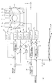
図1は実施例1による位置決め装置を示す。この位置決め装置は、直動テーブル1及び回転テーブル2を有し、直動テーブル1は、両サイドのガイド3a、3bによってY方向に拘束されている。また、ベースプレート(ガイド)4によってZ方向に拘束されている。
FIG. 1 shows a positioning device according to a first embodiment. This positioning device has a linear motion table 1 and a rotary table 2, and the linear motion table 1 is restrained in the Y direction by
このように直動テーブル1は、移動方向に直交する2方向をガイドによって支持され、両サイドに配置されたリニアモータ5a、5bは、直動テーブル1の移動方向であるX方向に推力を発生させる。リニアスケール6a、6bは、それぞれ直動テーブル1のX方向位置を計測する。回転テーブル2は、直動テーブル1に搭載され、図示しない駆動手段としてモータと、回転角度を検出する手段として高分解能のロータリエンコーダと、を備える。
Linear motion table 1 in this way, the two directions perpendicular to the moving direction is supported by the guide,
回転テーブル2の制御系は、回転テーブル2の回転角度指令値とフィードバック信号とから誤差を求める減算器7と、回転テーブル2のフィードバック制御を安定化させるためのPID補償器に代表される回転テーブル制御調整器8と、を備えている。モータアンプ9は、回転テーブル2のモータに駆動電流を流す。ロータリエンコーダカウンタ10は、回転テーブル2に搭載されたロータリエンコーダの信号をカウントして回転角度信号にする。さらに、減算器11、17、19、直動テーブル制御調整器12、リニアモータアンプ13a、13b、リニアスケールカウンタ14a、14b、加算器15、感度調整器16、18を備える。
The control system of the
減算器19は、ロータリエンコーダの検出値である回転角度信号から直動テーブル1の傾きを減算して回転テーブル制御用のフィードバック信号を作る。感度調整器18は、直動テーブル1の傾きを検出する減算器17による傾き信号をロータリエンコーダの感度に調整する。傾き検出手段を構成する減算器17は、直動テーブル1の両サイドに配置されたリニアスケール6a、6bの位置信号より直動テーブル1の傾き(検出値)を演算する。
The
減算器11は、直動テーブル1の位置指令値とフィードバック信号とから、直動テーブル1の位置誤差を演算する。直動テーブル制御調整器12は、直動テーブル1のフィードバック制御を安定化させるためのPID補償器に代表される調整器である。リニアモータアンプ13a、13bは、直動テーブル1の両サイドのリニアモータ5a、5bに電流を流す。リニアスケールカウンタ14a、14bは、直動テーブル1の両サイドに配置されているリニアスケール6a、6bからの信号をカウントして位置信号に変換する。加算器15は、両サイドのリニアスケール6a、6bからの位置信号を平均化処理し、直動テーブル1の移動方向の位置を検出する位置検出手段を構成する。感度調整器18は、平均化処理のための感度調整器である。この平均化処理した結果(検出値)を、直動テーブル1の位置を制御する制御系のフィードバック信号として使用する。この制御系は、両サイドのリニアスケール6a、6bの位置信号を平均化して、検出された直動テーブル中央位置が、位置指令値で設定されている位置になるように両サイドのリニアモータ5a、5bを駆動する。
The
直動テーブル1はガイド3a、3bにてY方向を拘束されており、このガイド3a、3bの加工精度及び取り付け精度によって、直動テーブル1の移動に伴う直動テーブル1の傾きが決定される。現在の加工精度及び取り付け精度が不十分なため、約1uradの傾きを生じてしまう。この傾きは、回転テーブル2が回転した結果ではないが、回転テーブル2に搭載された高分解能のロータリエンコーダで検出される。現在の高分解能のロータリエンコーダは約1〜2nradの分解能があり、直動テーブル1の傾きを十分検出できる性能をもっている。
The linear motion table 1 is constrained in the Y direction by
そのため、回転テーブル2の回転角度制御にロータリエンコーダの検出値である回転角度信号をフィードバック信号として使用した場合、ロータリエンコーダが直動テーブル1の傾きを検出して回転テーブル2を回転させる。その結果、回転テーブル上の保持手段に保持された被加工物が傾いてしまう。 Therefore, when the rotation angle signal that is the detection value of the rotary encoder is used as the feedback signal for the rotation angle control of the rotation table 2, the rotary encoder detects the inclination of the linear motion table 1 and rotates the rotation table 2. As a result, the workpiece held by the holding means on the rotary table is inclined.
本実施例の傾き検出手段は、直動テーブル1の両サイドに配置されたリニアスケール6a、6bとリニアスケールカウンタ14a、14bによって検出した位置信号より、減算器17によって直動テーブル1の傾きを演算する。演算して得た傾き(検出値)を、ロータリエンコーダの回転角度検出感度に合わせる感度調整器18を介して減算器19に入力し、ロータリエンコーダで検出した回転角度信号(検出値)から減算する。そして、減算器19の出力を、回転角度指令値に基づいて回転テーブル2の回転角度を制御する制御系のフィードバック信号として使用する。
The inclination detecting means of the present embodiment uses the
このフィードバック信号は、ロータリエンコーダにて検出される回転角度から、直動テーブル1の傾きによって生じた回転角度分を除去しているので、回転角度指令値に一致した信号になれば、減算器7にて演算する誤差がゼロとなる。このように、直動テーブル1が傾いても回転テーブル2を回転させない制御をすることで、回転テーブル上の被加工物の回転位置ズレを防ぎ、加工精度を向上させることができる。 Since this feedback signal removes the rotation angle generated by the inclination of the linear motion table 1 from the rotation angle detected by the rotary encoder, if the signal coincides with the rotation angle command value, the subtractor 7 The error calculated in is zero. In this way, by performing control not to rotate the rotary table 2 even if the linear motion table 1 is tilted, it is possible to prevent the rotational position deviation of the workpiece on the rotary table and improve the processing accuracy.
図2(a)は実施例2による位置決め装置を示す。本実施例は、実施例1による、直動テーブル1の位置をフィードバック制御するための制御系(第1の制御系)に加えて、直動テーブル1の傾きをフィードバック制御するための制御系(第2の制御系)を有する。そして、第2の制御系における直動テーブル1の傾き指令値を、回転テーブル2の回転角度指令値から減算して、回転テーブル2のフィードバック制御を行う制御系(第3の制御系)に与える。このために、実施例1の構成に加えて、減算器20、23、24、27、直動テーブル傾き制御調整器21、加算器22、感度調整器25、前記傾き指令値を生成する傾き指令値生成器26等を設ける。その他の点は実施例1と同様であるから同じ符号で表し、説明は省略する。
FIG. 2A shows a positioning apparatus according to the second embodiment. In this embodiment, in addition to the control system (first control system) for feedback control of the position of the linear motion table 1 according to the first embodiment, a control system for feedback control of the inclination of the linear motion table 1 ( A second control system). Then, the tilt command value of the linear motion table 1 in the second control system is subtracted from the rotation angle command value of the rotary table 2 and given to a control system (third control system) that performs feedback control of the rotary table 2. . For this purpose, in addition to the configuration of the first embodiment, the
直動テーブル1の傾きを制御する第2の制御系は、直動テーブル1の両サイドのリニアスケール6a、6bとリニアスケールカウンタ14a、14bによって検出した位置信号から傾きを計算する減算器24と、感度調整器25と、を有する。減算器24及び感度調整器25で演算された傾き(検出値)をフィードバックして、減算器20によって傾き指令値との誤差を演算する。演算した誤差をゼロにするための制御信号を直動テーブル傾き制御調整器21によって作り出している。
The second control system that controls the inclination of the linear motion table 1 includes a
直動テーブル傾き制御調整器21は、直動テーブル1の傾きを制御するフィードバック系を安定化させるためのPID調整器に代表される調整器を用いる。直動テーブル傾き制御調整器21によって作り出された制御信号は、直動テーブル1の両サイドに配置されたリニアモータ5a、5bで回転方向に推力が発生するように、リニアモータアンプ13a、13bに位相を180°ずらして与えられる。
The linear motion table
両サイドのリニアモータ5a、5bの推力の方向と大きさによって直動テーブル1の傾きを制御するが、直動テーブル1はガイド3a、3bによってY方向が拘束されているため、ガイドに倣った傾きで制御する必要がある。両サイドのリニアモータ5a、5bによってガイドに倣った傾きとは違う傾きに制御しようとすると、リニアモータの推力が飽和する。また、発熱が大きくなるなどの問題が生じる。このガイド3a、3bに倣った傾きで制御するために、移動方向の位置毎に直動テーブルの傾き指令値を生成する傾き指令値生成器26を設ける。
The inclination of the linear motion table 1 is controlled by the direction and magnitude of the thrusts of the
傾き指令値生成器26においては、以下のように傾き指令値を生成する。傾き制御を掛けない状態にて直動テーブル1を移動方向(X方向)に送り、各移動方向位置において、直動テーブル1の両サイドのリニアスケールカウンタ14a、14bと減算器24と感度調整器25とで演算して得た傾きを測定する。この測定結果より、移動方向位置と傾きとのデータ列を作成し、データ間は直線補間したデータベースを作成する。作成したデータベースを図2(b)に示す。このデータベースに基づき移動方向位置毎の傾き指令値を作成している。この傾き指令値によって、直動テーブル1はガイド3a、3bに倣った傾きで制御される。こうした制御をすることで、直動テーブル1の回転方向の剛性は、軸受けによる剛性に、制御によって発生する剛性が加わるため、大幅に向上する。
The tilt
直動テーブル1は、傾き指令値通り傾くので、回転テーブル2の回転角度指令値から直動テーブル1の傾き指令値を減算器27により減算した値(出力)を、回転テーブル2の回転角度を制御する第3の制御系の指令値として与える。与えられた指令値と高分解能のエンコーダによって検出した回転角度信号(検出値)を減算器7に入力して誤差を求め、この誤差をゼロにするようにモータでトルクを与え、回転テーブル2を制御する。このようなフィードバック制御によって、直動テーブル1の傾きの影響を受けずに回転テーブル上の被加工物を高精度に位置決めできる。
Since the linear motion table 1 tilts according to the tilt command value, the value (output) obtained by subtracting the tilt command value of the linear motion table 1 from the rotation angle command value of the rotary table 2 by the
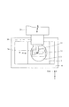
図3は、実施例1又は2による位置決め装置を搭載する加工機を示す。この装置は、直動テーブル1であるX軸テーブルと、Y軸テーブル29及びZ軸テーブル28と、Z方向を回転軸とする回転テーブル2であるC軸テーブルと、Y方向を回転軸とするスピンドル30と、を有する。さらに、Z軸テーブル28のY方向ガイドとY軸テーブル29のZ方向ガイドを兼ねた加工機の基準となるベース部材35、Y軸テーブル29のX方向を拘束するガイド32a、32b、Z軸テーブル28のX方向を拘束するガイド31a、31bを備える。工具34は、スピンドル30に取り付けられる。被加工物33は、C軸テーブルである回転テーブル2に搭載された保持手段に取り付けられ、スピンドル30によって旋回する工具34によって加工される。
FIG. 3 shows a processing machine equipped with the positioning device according to the first or second embodiment. This apparatus includes an X-axis table that is a linear motion table 1, a Y-axis table 29 and a Z-axis table 28, a C-axis table that is a rotary table 2 having the Z direction as a rotation axis, and a Y axis as a rotation axis.
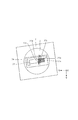
図4は、図3の加工機を上からみた平面図で、X−Y平面内での各軸テーブルと工具34と被加工物33の関係を示す。図5は、被加工物上を移動する工具34の軌跡37を示す。図4において、スピンドル30に取り付けられた工具34は、スピンドル30によってY軸回りに旋回している。旋回している工具34は、Y軸テーブル29によってY方向に走査させられる。被加工物33は、直動テーブル(X軸テーブル)1によってX方向に位置決めされるともに、工具34のY方向への走査に同期して、Z軸テーブル28によってZ方向に走査される。このようにして、被加工物33の表面を軌道37に沿って工具34が移動する。突き当て具36は、被加工物33を取り付けるときの取り付け位置を決めるものである。
FIG. 4 is a plan view of the processing machine of FIG. 3 as viewed from above, and shows the relationship among each axis table, the
1回目のY方向走査によって、図6に示す領域37aが加工され、2回目のY方向走査によって領域37b、3回目のY方向走査によって領域37cが加工される。このように微少加工領域を繋いで被加工物33を加工する。
The
この加工方法では、微少加工領域の配置精度が被加工物の加工精度に影響する。加工する途中にて、図7に示すようにX軸テーブルの傾きが生じた場合、従来方式による回転テーブルのフィードバック制御では、C軸テーブルが回転して被加工物33が傾いてしまう。すると、傾く前に加工した領域37a、37b、37cに対し、傾きを生じた後に加工した領域37d、37eの配置がズレてしまう。
In this machining method, the accuracy of arrangement of the minute machining area affects the machining accuracy of the workpiece. When the X-axis table is tilted as shown in FIG. 7 during the machining, the C-axis table is rotated and the
そこで、実施例1又は2の傾き制御により、リアルタイムにX軸テーブルである直動テーブル1の傾き分を補正して、C軸テーブに搭載された被加工物33の傾きを防ぐ。これにより、図8に示すように、X軸テーブルが傾いた後に加工された領域37g、37fが、X軸テーブルが傾く前の領域37a、37b、37cに対して回転位置ズレを生じるのを防ぎ、精度よく加工できる。
Therefore, the tilt control of the first or second embodiment corrects the tilt of the linear motion table 1 that is the X-axis table in real time, thereby preventing the tilt of the
1 直動テーブル
2 回転テーブル
3a、3b ガイド
4 ベースプレート
5a、5b リニアモータ
6a、6b リニアスケール
7、11、17、19、20、23、24、27 減算器
15、22 加算器
8 回転テーブル制御調整器
10 ロータリエンコーダカウンタ
12 直動テーブル制御調整器
14a、14b リニアスケールカウンタ
21 直動テーブル傾き制御調整器
26 傾き指令値生成器
DESCRIPTION OF
Claims (3)
前記直動テーブルに支持された回転テーブルと、
前記直動テーブルの傾きを検出する傾き検出手段と、
前記直動テーブルの位置を検出する位置検出手段と、
前記回転テーブルの回転角度を検出するロータリエンコーダと、
前記直動テーブルの位置指令値及び前記位置検出手段の検出値に基づいて、前記直動テーブルの前記移動方向の位置を制御する第1の制御系と、
前記位置指令値に基づいて、前記直動テーブルの傾き指令値を生成する傾き指令値生成器と、
前記傾き指令値及び前記傾き検出手段の検出値に基づいて、前記直動テーブルの傾きを制御する第2の制御系と、
前記回転テーブルの回転角度指令値から前記傾き指令値を減算する減算器と、
前記減算器の出力及び前記ロータリエンコーダの検出値に基づいて、前記回転テーブルの回転角度を制御する第3の制御系と、を有することを特徴とする位置決め装置。 A linear motion table supported by a guide in two directions orthogonal to the moving direction;
A rotary table supported by the linear motion table;
An inclination detecting means for detecting an inclination of the linear motion table;
Position detecting means for detecting the position of the linear motion table;
A rotary encoder for detecting a rotation angle of the rotary table;
A first control system that controls a position of the linear motion table in the moving direction based on a position command value of the linear motion table and a detection value of the position detection unit;
An inclination command value generator for generating an inclination command value of the linear motion table based on the position command value;
A second control system for controlling the inclination of the linear motion table based on the inclination command value and the detection value of the inclination detection means;
A subtractor for subtracting the tilt command value from the rotation angle command value of the rotary table;
And a third control system for controlling a rotation angle of the rotary table based on an output of the subtracter and a detection value of the rotary encoder.
前記位置決め装置に配置された保持手段と、
工具と、
前記工具を旋回させるスピンドルと、を備え、
前記保持手段に保持された被加工物を前記工具によって加工することを特徴とする加工機。 A positioning device according to claim 1 ;
Holding means arranged in the positioning device;
Tools,
A spindle for turning the tool,
A processing machine for processing a workpiece held by the holding means with the tool.
Priority Applications (1)
| Application Number | Priority Date | Filing Date | Title |
|---|---|---|---|
| JP2010127696A JP5587040B2 (en) | 2010-06-03 | 2010-06-03 | Positioning device |
Applications Claiming Priority (1)
| Application Number | Priority Date | Filing Date | Title |
|---|---|---|---|
| JP2010127696A JP5587040B2 (en) | 2010-06-03 | 2010-06-03 | Positioning device |
Publications (3)
| Publication Number | Publication Date |
|---|---|
| JP2011251378A JP2011251378A (en) | 2011-12-15 |
| JP2011251378A5 JP2011251378A5 (en) | 2013-07-18 |
| JP5587040B2 true JP5587040B2 (en) | 2014-09-10 |
Family
ID=45415746
Family Applications (1)
| Application Number | Title | Priority Date | Filing Date |
|---|---|---|---|
| JP2010127696A Expired - Fee Related JP5587040B2 (en) | 2010-06-03 | 2010-06-03 | Positioning device |
Country Status (1)
| Country | Link |
|---|---|
| JP (1) | JP5587040B2 (en) |
Families Citing this family (1)
| Publication number | Priority date | Publication date | Assignee | Title |
|---|---|---|---|---|
| CN108890389B (en) * | 2018-06-22 | 2019-09-24 | 华中科技大学 | A method of feed speed is planned using scale effect |
Family Cites Families (5)
| Publication number | Priority date | Publication date | Assignee | Title |
|---|---|---|---|---|
| JPH05305550A (en) * | 1992-05-06 | 1993-11-19 | Yokogawa Electric Corp | Working device |
| JPH0839375A (en) * | 1994-07-27 | 1996-02-13 | Mitsutoyo Corp | Table device |
| JP3312297B2 (en) * | 1999-07-02 | 2002-08-05 | 住友重機械工業株式会社 | Stage position control device |
| JP2002149241A (en) * | 2000-11-08 | 2002-05-24 | Canon Inc | Positioning device |
| JP5030653B2 (en) * | 2007-04-20 | 2012-09-19 | 株式会社牧野フライス製作所 | Numerical control machine tool and numerical control device |
-
2010
- 2010-06-03 JP JP2010127696A patent/JP5587040B2/en not_active Expired - Fee Related
Also Published As
| Publication number | Publication date |
|---|---|
| JP2011251378A (en) | 2011-12-15 |
Similar Documents
| Publication | Publication Date | Title |
|---|---|---|
| JP3217522B2 (en) | Precision positioning device | |
| JP4290639B2 (en) | Numerical control device and numerical control machine tool | |
| JP4559277B2 (en) | NC machine tool thermal displacement compensation method | |
| JP4299865B2 (en) | Machine tool control apparatus and control method | |
| JP5385330B2 (en) | High precision processing equipment | |
| WO2018216281A1 (en) | Laser machining device | |
| KR100450455B1 (en) | Servo control method | |
| US7096751B2 (en) | Measuring apparatus and accuracy analyzing apparatus having the same | |
| JP3811088B2 (en) | Servo control method | |
| JP6463926B2 (en) | Displacement compensation system for machine tools | |
| JP5587040B2 (en) | Positioning device | |
| US20060184257A1 (en) | Controller | |
| JP6803043B2 (en) | How to measure geometric error of machine tools | |
| JP5265274B2 (en) | Positioning control method and positioning control device for numerically controlled machine tool | |
| JP7134031B2 (en) | Numerical control method and numerical control device | |
| JP6623061B2 (en) | Machine tool and control method of machine tool | |
| JP2009104316A (en) | The position control method for rotating structure | |
| JP2008225780A (en) | Backlash correction method for pivoting shaft in machine tool | |
| JP3834433B2 (en) | XY stage | |
| JP5919125B2 (en) | Rotation holding device and rotation method in rotation holding device | |
| JP3363663B2 (en) | Movable stage device | |
| JP4591136B2 (en) | Two-dimensional positioning device | |
| JP2000005977A (en) | Controller for machine tool | |
| JP2008142860A (en) | Device and method for correcting rotary angle of pallet table | |
| JP2003271214A (en) | Numerical control device and pitch error correction method therefor |
Legal Events
| Date | Code | Title | Description |
|---|---|---|---|
| RD03 | Notification of appointment of power of attorney |
Free format text: JAPANESE INTERMEDIATE CODE: A7423 Effective date: 20120203 |
|
| RD04 | Notification of resignation of power of attorney |
Free format text: JAPANESE INTERMEDIATE CODE: A7424 Effective date: 20130228 |
|
| A521 | Request for written amendment filed |
Free format text: JAPANESE INTERMEDIATE CODE: A523 Effective date: 20130531 |
|
| A621 | Written request for application examination |
Free format text: JAPANESE INTERMEDIATE CODE: A621 Effective date: 20130531 |
|
| A977 | Report on retrieval |
Free format text: JAPANESE INTERMEDIATE CODE: A971007 Effective date: 20140219 |
|
| A131 | Notification of reasons for refusal |
Free format text: JAPANESE INTERMEDIATE CODE: A131 Effective date: 20140225 |
|
| A521 | Request for written amendment filed |
Free format text: JAPANESE INTERMEDIATE CODE: A523 Effective date: 20140425 |
|
| TRDD | Decision of grant or rejection written | ||
| A01 | Written decision to grant a patent or to grant a registration (utility model) |
Free format text: JAPANESE INTERMEDIATE CODE: A01 Effective date: 20140624 |
|
| A61 | First payment of annual fees (during grant procedure) |
Free format text: JAPANESE INTERMEDIATE CODE: A61 Effective date: 20140723 |
|
| R151 | Written notification of patent or utility model registration |
Ref document number: 5587040 Country of ref document: JP Free format text: JAPANESE INTERMEDIATE CODE: R151 |
|
| LAPS | Cancellation because of no payment of annual fees |