JP5586930B2 - Eyeglass frame shape measuring device - Google Patents
Eyeglass frame shape measuring device Download PDFInfo
- Publication number
- JP5586930B2 JP5586930B2 JP2009279943A JP2009279943A JP5586930B2 JP 5586930 B2 JP5586930 B2 JP 5586930B2 JP 2009279943 A JP2009279943 A JP 2009279943A JP 2009279943 A JP2009279943 A JP 2009279943A JP 5586930 B2 JP5586930 B2 JP 5586930B2
- Authority
- JP
- Japan
- Prior art keywords
- measurement
- point
- lens frame
- radial
- unit
- Prior art date
- Legal status (The legal status is an assumption and is not a legal conclusion. Google has not performed a legal analysis and makes no representation as to the accuracy of the status listed.)
- Active
Links
- 238000005259 measurement Methods 0.000 claims description 193
- 239000000523 sample Substances 0.000 claims description 117
- 230000033001 locomotion Effects 0.000 claims description 71
- 230000008859 change Effects 0.000 claims description 42
- 230000007246 mechanism Effects 0.000 claims description 36
- 238000001514 detection method Methods 0.000 claims description 30
- 238000010586 diagram Methods 0.000 description 15
- 238000000034 method Methods 0.000 description 14
- ZLHLYESIHSHXGM-UHFFFAOYSA-N 4,6-dimethyl-1h-imidazo[1,2-a]purin-9-one Chemical compound N=1C(C)=CN(C2=O)C=1N(C)C1=C2NC=N1 ZLHLYESIHSHXGM-UHFFFAOYSA-N 0.000 description 6
- 230000002093 peripheral effect Effects 0.000 description 6
- 230000001154 acute effect Effects 0.000 description 5
- 238000012986 modification Methods 0.000 description 4
- 230000004048 modification Effects 0.000 description 4
- 238000012545 processing Methods 0.000 description 4
- 239000013256 coordination polymer Substances 0.000 description 3
- 238000013461 design Methods 0.000 description 3
- 238000006073 displacement reaction Methods 0.000 description 3
- 241001422033 Thestylus Species 0.000 description 2
- 230000005540 biological transmission Effects 0.000 description 2
- 238000012937 correction Methods 0.000 description 2
- 230000007423 decrease Effects 0.000 description 2
- 239000000428 dust Substances 0.000 description 2
- 230000005484 gravity Effects 0.000 description 2
- 230000004913 activation Effects 0.000 description 1
- 230000015572 biosynthetic process Effects 0.000 description 1
- 230000006870 function Effects 0.000 description 1
- 238000003780 insertion Methods 0.000 description 1
- 230000037431 insertion Effects 0.000 description 1
- 238000000691 measurement method Methods 0.000 description 1
- 230000003287 optical effect Effects 0.000 description 1
- 230000010355 oscillation Effects 0.000 description 1
- 238000003786 synthesis reaction Methods 0.000 description 1
Images


Classifications
-
- G—PHYSICS
- G01—MEASURING; TESTING
- G01B—MEASURING LENGTH, THICKNESS OR SIMILAR LINEAR DIMENSIONS; MEASURING ANGLES; MEASURING AREAS; MEASURING IRREGULARITIES OF SURFACES OR CONTOURS
- G01B5/00—Measuring arrangements characterised by the use of mechanical techniques
- G01B5/20—Measuring arrangements characterised by the use of mechanical techniques for measuring contours or curvatures
-
- B—PERFORMING OPERATIONS; TRANSPORTING
- B24—GRINDING; POLISHING
- B24B—MACHINES, DEVICES, OR PROCESSES FOR GRINDING OR POLISHING; DRESSING OR CONDITIONING OF ABRADING SURFACES; FEEDING OF GRINDING, POLISHING, OR LAPPING AGENTS
- B24B9/00—Machines or devices designed for grinding edges or bevels on work or for removing burrs; Accessories therefor
- B24B9/02—Machines or devices designed for grinding edges or bevels on work or for removing burrs; Accessories therefor characterised by a special design with respect to properties of materials specific to articles to be ground
- B24B9/06—Machines or devices designed for grinding edges or bevels on work or for removing burrs; Accessories therefor characterised by a special design with respect to properties of materials specific to articles to be ground of non-metallic inorganic material, e.g. stone, ceramics, porcelain
- B24B9/08—Machines or devices designed for grinding edges or bevels on work or for removing burrs; Accessories therefor characterised by a special design with respect to properties of materials specific to articles to be ground of non-metallic inorganic material, e.g. stone, ceramics, porcelain of glass
- B24B9/14—Machines or devices designed for grinding edges or bevels on work or for removing burrs; Accessories therefor characterised by a special design with respect to properties of materials specific to articles to be ground of non-metallic inorganic material, e.g. stone, ceramics, porcelain of glass of optical work, e.g. lenses, prisms
- B24B9/144—Machines or devices designed for grinding edges or bevels on work or for removing burrs; Accessories therefor characterised by a special design with respect to properties of materials specific to articles to be ground of non-metallic inorganic material, e.g. stone, ceramics, porcelain of glass of optical work, e.g. lenses, prisms the spectacles being used as a template
Landscapes
- Engineering & Computer Science (AREA)
- Chemical & Material Sciences (AREA)
- Ceramic Engineering (AREA)
- Inorganic Chemistry (AREA)
- Mechanical Engineering (AREA)
- Physics & Mathematics (AREA)
- General Physics & Mathematics (AREA)
- A Measuring Device Byusing Mechanical Method (AREA)
- Eyeglasses (AREA)
Description
本発明は、眼鏡フレームのレンズ枠(リム)の三次元形状を測定する眼鏡枠形状測定装置に関する。 The present invention relates to a spectacle frame shape measuring apparatus for measuring a three-dimensional shape of a lens frame (rim) of a spectacle frame.
眼鏡フレーム保持機構に保持された眼鏡フレームのレンズ枠の溝に測定子を押し当てて挿入し、レンズ枠の変化に追従して移動する測定子の移動位置を検知してレンズ枠の動径方向(XY方向)及び動径方向に垂直な方向(Z方向)の三次元形状を得る眼鏡枠形状測定装置が種々ある(例えば、特許文献1、2、3、4等を参照)。
The probe is pressed into the lens frame groove of the spectacle frame held by the spectacle frame holding mechanism and inserted, and the moving position of the probe moving following the change of the lens frame is detected to detect the moving direction of the lens frame. There are various eyeglass frame shape measuring devices that obtain a three-dimensional shape in the direction (XY direction) and the direction perpendicular to the radial direction (Z direction) (see, for example,
この種の装置の測定機構は、図14に示されるように、レンズ枠FWに対して回転される回転ベースRBと、測定子STが上端に取り付けられた測定子軸SAを上下方向(Z方向)に移動可能に保持し、回転ベースRBの回転中心COを通る径方向に移動可能に回転ベースRBに設けられた移動ベースVBと、測定子STをレンズ枠FWの溝に押し当てる測定圧を発生するために、移動ベースVBをレンズ枠FW側に付勢する付勢機構と、により構成されている。回転ベースRBの回転により測定子STがレンズ枠の変化に追従して移動され、このときの測定子STの移動を検知することにより、レンズ枠の三次元形状が測定される。 As shown in FIG. 14, the measuring mechanism of this type of apparatus has a rotating base RB rotated with respect to the lens frame FW and a measuring element axis SA having a measuring element ST attached to the upper end in the vertical direction (Z direction). ) And a moving base VB provided on the rotating base RB so as to be movable in the radial direction passing through the rotation center CO of the rotating base RB, and a measurement pressure for pressing the measuring element ST against the groove of the lens frame FW. In order to generate | occur | produce, it is comprised by the urging mechanism which urges | biases the movement base VB to the lens frame FW side. The measuring element ST is moved following the change of the lens frame by the rotation of the rotating base RB, and the three-dimensional shape of the lens frame is measured by detecting the movement of the measuring element ST at this time.
また、近年ではレンズ枠の反りの大きな眼鏡フレームが多くなってきているため、測定子は針状の先端を有するものが採用されている。 In recent years, the number of spectacle frames with a large warp of the lens frame has increased, and therefore, a probe having a needle-like tip has been adopted.
レンズ枠の形状を精度良く測定するためには、測定子によりレンズ枠に掛かる力が過剰にならず、レンズ枠の変化に対して測定子ができるだけ滑らかに追従されることが好ましい。しかし、従来の測定機構においては、直線部分が長いレンズ枠を測定する場合にレンズ枠に掛かる力が過大となり、レンズ枠を変形させやすい問題があった。すなわち、図14に示されるように、測定子STの先端には付勢機構による測定圧PSの他、回転ベースRBの回転力が与えられている。回転ベースRBの回転力は比較的大きく、レンズ枠FWに対して測定子STの先端が斜めに当る状態では、レンズ枠FWが変化する方向に対して大きく外れた外側方向に力PCが働くため、レンズ枠FWを変形させてしまうことになる。この場合には、レンズ枠FWの測定精度が低下する。 In order to accurately measure the shape of the lens frame, it is preferable that the force applied to the lens frame by the measuring element does not become excessive, and the measuring element follows the change of the lens frame as smoothly as possible. However, the conventional measuring mechanism has a problem that when a lens frame having a long straight portion is measured, the force applied to the lens frame becomes excessive, and the lens frame is easily deformed. That is, as shown in FIG. 14, the rotational force of the rotation base RB is given to the tip of the measuring element ST in addition to the measurement pressure PS by the urging mechanism. The rotational force of the rotation base RB is relatively large, and in the state where the tip of the tracing stylus ST strikes obliquely with respect to the lens frame FW, the force PC acts in the outward direction that is greatly deviated from the direction in which the lens frame FW changes. The lens frame FW will be deformed. In this case, the measurement accuracy of the lens frame FW decreases.
また、針状の先端を有する測定子STにおいては、測定子STの先端がレンズ枠FWに対して鋭角な角度で当ると、レンズ枠FWの繋ぎ目の段差に測定子STの先端が引っかかりやすく、制度良くレンズ枠の形状を測定できなくなってしまう。 Further, in the measuring element ST having a needle-like tip, when the leading end of the measuring element ST hits the lens frame FW at an acute angle, the leading end of the measuring element ST is likely to be caught in the step of the joint of the lens frame FW. It becomes impossible to measure the shape of the lens frame systematically.
また、レンズ枠FWは眼鏡フレーム保持機構が持つクランプピンCPによりクランプされるが、クランプピンCP付近でレンズ枠FWの反り(Z方向の変化)が大きく、レンズ枠FWに対して測定子STの先端が鋭角な角度で当っていると、測定子STがクランプピンCPと干渉していまい、精度良くレンズ枠の形状を測定できなくなってしまう。 Further, the lens frame FW is clamped by the clamp pin CP of the spectacle frame holding mechanism, but the warp (change in the Z direction) of the lens frame FW is large in the vicinity of the clamp pin CP. If the tip is hit at an acute angle, the measuring element ST does not interfere with the clamp pin CP, and the shape of the lens frame cannot be measured with high accuracy.
さらにまた、近年ではフレームデザインの多様化により左右方向に長く延びた形状のレンズ枠や窪み形状のレンズ枠が出現してきているが、レンズ枠FWに対する測定子STの先端の角度が鋭角になり過ぎると、測定子軸SAがレンズ枠と干渉し、精度良く測定できなくなってしまう。 Further, in recent years, a lens frame having a shape extending in the left-right direction or a lens frame having a hollow shape has appeared due to diversification of frame designs, but the angle of the tip of the measuring element ST with respect to the lens frame FW becomes too acute. Then, the tracing stylus axis SA interferes with the lens frame, and measurement cannot be performed with high accuracy.
また、レンズ枠の反りの大きな高カーブフレームをも精度良く測定する上では、レンズ枠の動径方向に垂直な方向(Z方向)の変化に対しても測定子が滑らかに追従されることが好ましい。レンズ枠が変化するZ方向の全範囲に亘って測定子を追従させる機構では、追従機構も大きくなり、重量も増すため、測定子の滑らかな動きに支障をきたし、測定精度が劣るようになる。また、測定子がレンズ枠の溝から外れやすくなる問題もある。 In addition, when measuring a high-curve frame with a large warp of the lens frame with high accuracy, the probe can smoothly follow changes in the direction perpendicular to the radial direction of the lens frame (Z direction). preferable. In the mechanism that causes the tracing stylus to follow the entire range in the Z direction in which the lens frame changes, the tracking mechanism also increases in size and weight, which hinders the smooth movement of the stylus and results in poor measurement accuracy. . In addition, there is a problem that the measuring element is easily detached from the groove of the lens frame.
本発明は、上記従来装置の問題点に鑑み、精度良くレンズ枠の形状を測定できる眼鏡枠形状測定装置を提供することを技術課題とする。 In view of the above-described problems of the conventional apparatus, it is an object of the present invention to provide a spectacle frame shape measuring apparatus that can accurately measure the shape of a lens frame.
上記課題を解決するために、本発明は以下のような構成を備えることを特徴とする。
(1) 眼鏡フレームを所期する状態に保持する眼鏡フレーム保持ユニットと、眼鏡フレームのレンズ枠の溝に挿入されて押し当てられる針状の先端形状を持つ測定子と、を備え、前記測定子の移動位置を検知して前記眼鏡フレーム保持ユニットに保持されたレンズ枠の動径方向(XY方向)及び動径方向に垂直な方向(Z方向)の三次元形状を測定する眼鏡枠形状測定装置において、前記測定子が上部に取り付けられた測定子軸を持つ測定子保持ユニットであって、前記測定子軸のZ方向の位置を自由に移動可能に保持すると共に、前記測定子の先端方向に前記測定子軸を移動可能に保持し、且つ前記測定子の先端をレンズ枠の溝に押し当てる測定圧を付与する測定圧付与機構と、動径方向における前記測定子の先端の向きを変えるために、前記測定子軸をZ方向に設定された軸を中心に回転する回転手段と、が設けられた測定子保持ユニットと、前記測定子保持ユニットを動径方向に2次元的に移動させる動径方向移動手段と、前記測定子の動径方向の位置を検知する動径検知手段であって、前記測定子保持ユニットの動径方向の位置を検知する第1動径検知手段と、前記測定子保持ユニットに対する前記測定子の動径方向の位置を検知する第2動径検知手段と、を持つ動径検知手段と、測定開始後に得られた前記動径検知手段の検知結果に基づいて次の測定位置における前記回転手段の回転角及び前記測定子保持ユニットの動径位置を得て、得られた結果に基づいて前記回転手段及び動径方向移動手段の動作を制御する制御手段と、を備えることを特徴とする。
(2) (1)の眼鏡枠形状測定装置において、前記制御手段は、前記測定子の先端の向きを、レンズ枠の測定済みの動径情報に基づいてレンズ枠の未測定部分の動径変化を予測し、予測した動径変化の略法線方向の第1方向か、レンズ枠内に設定されている所定位置に対する測定位置の動径方向の第2方向か、前記第1方向と第2方向の間の第3方向か、の何れかに決定して前記回転手段の駆動を制御することを特徴とする。
(3) (1)の眼鏡枠形状測定装置において、前記測定子保持ユニットは、前記測定子軸をZ方向に移動可能に保持するZ方向保持ユニットと、前記Z方向保持ユニットをZ方向に移動させるZ移動手段と、前記測定子のZ方向の位置を検知するZ位置検知手段であって、前記Z方向保持ユニットのZ方向の位置を検知する第1Z位置検知手段と、前記Z方向保持ユニットに対する前記測定子のZ方向の移動位置を検知する第2Z位置検知手段と、を備え、前記制御手段は、測定開始後に得られたZ位置検知手段の検知結果に基づいて次の測定位置における前記Z方向保持ユニットの位置を得て、得られた結果に基づいて前記Z移動手段の駆動を制御することを特徴とする。
In order to solve the above problems, the present invention is characterized by having the following configuration.
(1) A spectacle frame holding unit that holds the spectacle frame in an expected state, and a measuring element having a needle-like tip shape that is inserted into and pressed against a groove of the lens frame of the spectacle frame, and the measuring element Eyeglass frame shape measuring device for detecting the moving position of the lens frame and measuring the three-dimensional shape of the lens frame held in the eyeglass frame holding unit in the radial direction (XY direction) and the direction perpendicular to the radial direction (Z direction) In the above, the measuring element is a measuring element holding unit having a measuring element shaft attached to an upper part thereof, and holds the position of the measuring element axis in the Z direction so as to be freely movable, and in the distal direction of the measuring element. In order to change the direction of the tip of the measuring element in the radial direction, and a measuring pressure applying mechanism that holds the measuring element shaft movably and applies a measuring pressure that presses the tip of the measuring element against the groove of the lens frame In addition, Rotating means for rotating the tracing stylus axis about an axis set in the Z direction, and a radial holding direction unit for moving the tracing stylus holding unit two-dimensionally in the radial direction. A moving means, a moving diameter detecting means for detecting a position of the measuring element in the radial direction, a first moving diameter detecting means for detecting a position of the measuring element holding unit in the moving direction, and the holding of the measuring element A second radial detection means for detecting a radial direction position of the probe relative to the unit; a radial detection means having a second measurement based on a detection result of the radial detection means obtained after the start of measurement; Control means for obtaining the rotation angle of the rotating means at the position and the radial position of the probe holding unit, and controlling the operation of the rotating means and the radial movement means based on the obtained results. It is characterized by.
(2) In the spectacle frame shape measuring apparatus according to (1), the control means changes the direction of the tip of the measuring element based on the measured radius information of the lens frame and changes the radius of the unmeasured portion of the lens frame. The first direction in the substantially normal direction of the predicted radial change, the second direction in the radial direction of the measurement position with respect to a predetermined position set in the lens frame, or the first direction and the second direction. The driving of the rotating means is controlled by determining one of the third directions between the directions .
(3) In the spectacle frame shape measuring apparatus according to (1), the probe holding unit moves the Z axis holding unit in the Z direction, and a Z direction holding unit that holds the probe axis movably in the Z direction. Z moving means for detecting, Z position detecting means for detecting the position of the measuring element in the Z direction, the first Z position detecting means for detecting the Z direction position of the Z direction holding unit, and the Z direction holding unit Second Z position detecting means for detecting a movement position of the measuring element in the Z direction with respect to the control element, and the control means is configured to detect the position at the next measurement position based on the detection result of the Z position detecting means obtained after the start of measurement. The position of the Z direction holding unit is obtained, and the driving of the Z moving means is controlled based on the obtained result .
本発明によれば、精度良くレンズ枠の形状を測定できる。また、レンズ枠の変形の可能性を低減でき、多様化するレンズ枠のデザインにも柔軟に対応した測定を行える。 According to the present invention, the shape of the lens frame can be measured with high accuracy. In addition, the possibility of deformation of the lens frame can be reduced, and measurement that can flexibly cope with diversified lens frame designs can be performed.
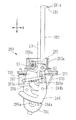
以下、本発明の実施の形態を図面に基づいて説明する。図1は、眼鏡枠形状測定装置の外観略図である。眼鏡枠形状測定装置1は、眼鏡フレームFを所期する状態に保持するフレーム保持ユニット100と、フレーム保持ユニット100に保持された眼鏡フレームのレンズ枠の溝に測定子を挿入し、測定子の移動を検出することによりレンズ枠(玉型)の三次元形状を測定する測定ユニット200と、を備える。測定ユニット200はフレーム保持ユニット100の下に配置されている。また、型板TP(又は眼鏡フレームに取り付けられていたデモレンズの場合も含む)を測定する際に使用される型板ホルダ310を着脱自在に取り付けるための取り付け部300が、装置1の左右中央の後方に配置されている。なお、型板ホルダ310は、特開2000−317795号公報等に記載された周知のものを使用することができる。
Hereinafter, embodiments of the present invention will be described with reference to the drawings. FIG. 1 is a schematic external view of a spectacle frame shape measuring apparatus. The spectacle frame
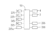
測定装置1の筐体の前側には測定開始用のスイッチ等を持つスイッチ部4が配置されている。測定装置1の筐体の後側には、タッチパネル式のディスプレイを持つパネル部3が配置されている。レンズの周縁加工に際し、パネル部3により玉型データに対するレンズのレイアウトデータ、レンズの加工条件等が入力される。測定装置1で得られたレンズ枠の三次元形状データ及びパネル部3で入力されたデータは、眼鏡レンズ周縁加工装置に送信される。なお、測定装置1は、特開2000−314617号公報等と同じく、眼鏡レンズ周縁加工装置に組み込まれる構成としてもよい。
A
図2は、眼鏡フレームFが保持された状態のフレーム保持ユニット100の上面図である。フレーム保持ユニット100の下側には、測定ユニット200が備えられている。保持部ベース101上には眼鏡フレームFを略水平に保持するための前スライダー102と後スライダー103が載置されている。前スライダー102と後スライダー103は、その中心線FLを中心に2つのレール111上を対向して摺動可能に配置されていると共に、バネ113により常に両者の中心線FLに向かう方向に引っ張られている。
FIG. 2 is a top view of the
前スライダー102には、眼鏡フレームFのレンズ枠をその厚み方向からクランプするためのクランプピン130a,130bがそれぞれ2箇所に配置されている。同様に後スライダー103には眼鏡フレームFのレンズ枠をその厚み方向からクランプするためのクランプピン131a,131bがそれぞれ2箇所に配置されている。また、型板TPを測定するときは、前スライダー102及び後スライダー103が開放され、周知の型板保持治具が所定の取付け位置140に配置されて使用される。このフレーム保持ユニット100の構成は、例えば、特開2000−314617号公報等に記載された周知のものが使用できる。
On the
眼鏡フレームFは、図示されるように、眼鏡装用時のレンズ枠の下方向が前スライダー102側に位置され、レンズ枠の上方向が後スライダー103側に位置される。左右のレンズ枠のそれぞれの下方向及び上方向に位置するクランプピンにより、フレームFは所定の測定状態に保持される。
As shown in the figure, the spectacle frame F is positioned such that the lower direction of the lens frame when wearing spectacles is positioned on the
測定ユニット200の構成例を、図3〜図8に基づいて説明する。測定ユニット200は、レンズ枠の溝に挿入される測定子281を保持するセンサユニット(測定子保持ユニット)250と、センサユニット250をXYZ方向に移動させる移動ユニット210と、を備える。XY方向はフレーム保持ユニット100により保持されるフレームFの測定平面(レンズ枠の動径方向)と平行であり、Z方向は測定平面(レンズ枠の動径方向)に垂直な方向である。センサユニット250は、測定子281が上部に取り付けられた測定子軸282を備え、レンズ枠のZ方向の変化に追従して測定子281が移動するように測定子軸282をZ方向に移動可能に保持すると共に、測定子281の先端方向に測定子軸282を移動可能に保持し、且つ測定子281の先端をレンズ枠の溝に押し当てる測定圧を付与する測定圧付与機構が設けられている。
A configuration example of the measurement unit 200 will be described with reference to FIGS. The measuring unit 200 includes a sensor unit (measuring element holding unit) 250 that holds a
図3〜5は、移動ユニット210の構成を説明する図である。図3は、移動ユニット210の上方からの斜視図であり、図4は、移動ユニット210の下方からの斜視図である。図5は、Z移動ユニット220とY移動ユニット230の上面斜視図(X移動ユニット240とベース部211を取り外した状態の斜視図)である。
3 to 5 are diagrams illustrating the configuration of the moving
移動ユニット210は、大別して、センサユニット250をZ方向に移動させるZ移動ユニット220と、センサユニット250及びZ移動ユニット220を保持しY方向へ移動させるY移動ユニット230と、センサユニット250をZ移動ユニット220及びY移動ユニット230と共にX方向に移動させるX移動ユニット240と、を備える。
The moving
X移動ユニット240は、概略的に次のように構成されている。水平方向(XY方向)に伸展した方形状の枠を持つベース部211の下方に、X方向に延びるガイドレール241が取り付けられている。ガイドレール241に沿って、Y移動ユニット230のYベース230aがX方向に移動可能に取り付けられている。また、ベース部211には、パルスモータ245が取り付けられている。モータ245の回転軸には、X方向に延びる送りネジ242が取り付けられている。そして、Yベース230aに固定されたナット部246が送りネジ242に螺合されている。これにより、モータ245が回転されると、Yベース230aがX方向に移動される。
The
なお、X移動ユニット240のX方向の移動範囲は、眼鏡フレームの左右のレンズ枠を測定可能にするために、センサユニット250が搭載されるYベース230aを眼鏡フレームの左右幅以上に移動可能な長さを持つ。
Note that the X movement range of the
また、Y移動ユニット230は、概略的に次のように構成されている。Yベース230aにY方向に延びるガイドレール231が取り付けられ、このガイドレール231に沿ってZベース220aがY方向に移動可能に取り付けられている。Yベース230aにはY移動用のパルスモータ235とY方向に延びる送りネジ232が回転可能に取り付けられている。モータ235の回転は、ギヤ等の回転伝達機構を介して送りネジ232に伝達される。送りネジ232には、Zベース220aに取り付けられたナット227が螺合されている。これらの構成により、モータ235が回転されると、Zベース220aがY方向に移動される。
The
X移動ユニット240及びY移動ユニット230によりXY移動ユニットが構成される。センサユニット250をXY方向に移動させる範囲は、測定可能なレンズ枠の動径よりも大きくされている。これにより、センサユニット250により動径方向に移動可能に保持された測定子軸282の移動範囲を小さくできる。また、センサユニット250のXY方向の移動位置は、後述する制御部50によりモータ245及び235が駆動されるパルス数によって検知され、センサユニット250のXY方向の位置を検知する第1のXY位置検知ユニットがモータ245,235及び制御部50により構成される。センサユニット250のXY位置検知ユニットとしては、モータ245及び235のパルス制御で検知する他、モータ245及び235のそれぞれの回転軸に取り付けられたエンコーダ等のセンサを使用する構成でも良い。
The
Z移動ユニット220は、概略的に次のように構成されている。Zベース220aにはZ方向に延びるガイドレール221が形成され、このガイドレール221に沿ってセンサユニット250が取り付けられた移動ベース250aがZ方向に移動可能に保持されている。また、Zベース220aにZ移動用のパルスモータ225が取り付けられていると共に、Z方向に延びる送りネジ(図示を略す)が回転可能に取り付けられている。そして、センサユニット250のベース250aに取り付けられたナットに螺合されている。モータ225の回転はギヤ等の回転伝達機構を介して送りネジ222に伝達され、送りネジ222の回転によりセンサユニット250がZ方向に移動される。センサユニット250のZ方向の移動位置は、後述する制御部50によってモータ225が駆動されるパルス数により検知され、センサユニット250のZ方向の位置を検知する第1のZ位置検知ユニットがモータ225及び制御部50により構成される。センサユニット250のZ位置検知ユニットとしては、モータ225のパルス制御で検知する他、モータ225の回転軸に取り付けられたエンコーダ等のセンサを使用する構成でも良い。
The
以上のようなX方向、Y方向及びZ方向の各移動機構は、実施形態に限られず、周知の機構が採用できる。例えば、XY移動ユニットは、図10に示すように、モータ403により回転中心CO(Z方向の軸)を中心に回転される回転ベース401と、回転ベース401に設けられたガイドレール411であって、中心COを中心にして径線方向に平行に設けられたガイドレール411と、モータ等の駆動機構421によってガイドレール411に沿って移動される水平移動ユニット420と、により構成することができる。センサユニット250及びZ移動ユニット220は水平移動ユニット420に搭載される。また、特開2006−350264号公報に記載されているように、測定子281を持つセンサユニット250を直線移動させる代わりに、回転ベースの中心に対して円弧起動で移動させる構成としても良い。この他、ロボットアームによるXY移動ユニットを構成することもできる。また、Z移動ユニットについても、回転可能なアームを持つ回転機構を組み合わせた構成とすることもできる。
Each moving mechanism in the X direction, the Y direction, and the Z direction as described above is not limited to the embodiment, and a known mechanism can be adopted. For example, as shown in FIG. 10, the XY moving unit includes a
次に、センサユニット250の構成を、図6〜9により説明する。センサユニット250は、測定子281が上端に取り付けられた測定子軸282を備え、測定子軸282をZ方向に移動可能に保持すると共に、測定子281の先端が向く方向に測定子軸282を移動可能に保持する保持ユニット(以下、VHユニットと呼ぶ)280を備える。VHユニット280は、好ましくは、測定子軸282を水平方向に移動可能にするために、測定子軸282を測定子281の先端が向く方向に傾倒可能に保持する。また、センサユニット250は、好ましくは、測定子281の先端が向くXY方向を変えるために、VHユニット280をZ方向に延びる中心軸LOを中心に回転させる回転ユニット260を備える。
Next, the configuration of the
図6(a)は、センサユニット250の上方斜視図であり、図6(b)は回転ユニット260の説明図である。図7はVHユニット280の斜視図である。図8はVHユニット280の構成図である。図9はVHユニット280の側面図である。
6A is an upper perspective view of the
回転ユニット260の構成を説明する。図8に示されるVHユニット280は、図6(b)に示される回転ベース261に取り付けられている。回転ベース261は、図6(a)に示される筒形状を持つ保持カバー251の内部で、Z方向に延びる中心軸LOを中心にして回転可能に保持されている。保持カバー251は、Z移動ユニット220によりZ方向に移動される移動ベース250aに取り付けられている。図6(b)に示されるように、回転ベース261の下部の外周には、大径ギア262が形成されている。一方、図6(a)に示されるように、保持カバー251に取り付けられた取り付け板252にDCモータ265が取り付けられている。モータ265の回転軸にピニオンギア266が固定され、ピニオンギア266の回転は、取り付け板252に回転可能に設けられたギア263を介して、大径ギア262に伝達される。したがって、モータ265の回転により、回転ベース261が中心軸LOの軸回りに回転される。モータ265の回転は、モータ265に一体的に取り付けられたエンコーダ(センサ)265aにより検出され、エンコーダ265aの出力から回転ベース261(すなわち、VHユニット280)の回転角が検知される。回転ベース261の回転の原点位置は、図示を略す原点位置センサにより検知される。
The configuration of the
次に、VHユニット280の構成を説明する。VHユニット280は、測定子281が上部に取り付けられ測定子軸282を備える。測定子軸282は、測定子281の先端が向く方向(測定子281の先端と測定子軸282の軸中心を結ぶ方向のH方向)に傾倒可能に保持される。
Next, the configuration of the
測定子281は、レンズ枠の反りが大きく、Z方向に大きく(45度以上に)傾斜したレンズ枠の溝にも挿入可能な厚みと幅を持つ針状に形成されている。この例では、測定子281の強度を持たすために、測定子281は先端に向かって徐々に径が細くなる形状に形成されている。また、測定子281の先端部281aは丸くされ、好ましくは球状に形成されている。先端部281aの球状形状の半径は、通常のレンズ枠の溝に挿入可能なサイズであり、好ましくは、0.3〜0.5mmである。球状形状の半径が0.3mmよりも小さいと、レンズ枠の繋ぎ目で生じる段差を乗り越え難くなる。球状形状の半径が0.5mmよりも大きすぎると、レンズ枠の溝の幅が狭いときに、先端部281aが入り難くなり、Z方向の変化の大きなレンズ枠の測定時に測定子281が外れやすくなる。
The measuring
図7及び図8において、揺動ベース285は、回転ベース261に支持された軸(支点)S1を中心にして軸受け283aを介して、測定子281の先端方向(H方向)に傾倒可能に保持されている。揺動ベース285は、図8上で測定子281の先端方向に延びたアーム部285aを持つ。また、図8上でZ方向に延びる測定子軸282は、軸(支点)S2を中心にして軸受け283bを介して測定子281の先端方向に傾倒可能にアーム部285aに保持されている。この構成により、測定子軸282はその傾倒角度を維持したまま、軸S1の位置(すなわち、回転ベース261)に対してZ方向に移動可能とされる。
7 and 8, the
なお、測定子軸282の動きをより軽くするために、センサユニット250上での測定子281の動径方向の移動範囲は、XY移動ユニットの移動可能範囲よりも小さくされ、また、測定子281のZ方向の移動範囲は、Z移動ユニットの移動可能範囲よりも小さくされていることが好ましい。これにより、レンズ枠の変化に対する測定子281の追従機構が小型化及び軽量化され、測定子281の滑らかな動きが実現される。
In order to make the movement of the
軸S2の下方に延びた測定子軸282の下部には、軸S2を支点とした測定子軸282の回転角の検知に使用されるギヤ板284が取り付けられている。また、揺動ベース285の下方には第1エンコーダ(センサ)286が取り付けられている。そして、エンコーダ286の回転軸に取り付けられたピニオン286aが、ギヤ板284に形成されたギヤ284aに噛み合わされている。このため、エンコーダ286により、軸S2を中心とした測定子軸282の傾倒方向(H方向)の回転角が検知される。
A
また、揺動ベース285には、軸S2より下方の位置で、軸S2を支点とした回転角の検知に使用されるギヤ板287が固定されている。一方、回転ベース261の下方に固定ブロック290が取り付けられている。固定ブロック290には第2エンコーダ(センサ)288が取り付けられている。そして、エンコーダ288の回転軸に取り付けられたピニオン288aが、ギヤ板287に形成されたギヤ287aに噛み合わされている。この構成により、軸S1を中心とした揺動ベース285の回転角がエンコーダ288によって検知される。図8上において、回転ベース261の回転の中心軸LOは、本実施形態では、軸S1と軸S2が同じ高さ位置する状態で、軸S1と軸S2の中央を通るように設定されているが、これは軸S1と軸S2の中央でなくても良い。
Further, a
なお、VHユニット280の構成においては、2つのエンコーダ286,288により、センサユニット250に設定されている所定の基準点(中心軸LO)に対する測定子281(先端部281a)のXY位置を検知する第2のXY位置検知ユニットが構成される。また、2つのエンコーダ286,288により、Z方向の基準点(支点S1の高さ)に対する測定子281のZ方向の位置を検知する第3のZ位置検知ユニットが構成される。エンコーダ286,288の代わりに、2次元CCD又は2つのラインセンサの組合わせ等による周知の光学的なセンサを使用することもできる。
In the configuration of the
また、VHユニット280には、測定子281の先端をレンズ枠の溝に押し当てる測定圧を与える測定圧付与機構が設けられている。図8の例では、固定ブロック290と測定子軸282との間に、測定圧発生の付勢部材としての引っ張りバネ291が架け渡されている。バネ291の付勢により、軸S2を中心にして測定子281の先端方向に測定子軸282が傾くように測定圧が常時掛けられる。測定圧付与機構は、バネ291の付勢部材を使用する他、モータ等の駆動源を使用することもできる。
Further, the
図8において、測定子軸282の下方に位置するギヤ板284には、図8の紙面に垂直な方向に突出したピン284bが固定されている。ピン284bは、測定子281の先端方向に測定子軸282が一定角度以上に傾倒されることを制限するために使用される。図9には、図8のVHユニット280の側面図が示される。回転ベース261の下方に制限板292が取り付けられている。制限板292には、ピン284bが接触する接触部292aが形成されている。測定子軸282はバネ291により、軸S2を支点として図8及び図9上の右側方向に傾倒するように付勢されているが、ピン284bが制限板292の接触部292aに接触することにより、測定子軸282の傾倒が制限される。その制限位置は、測定子軸282がZ方向に略平行になる位置までに設定されている。
In FIG. 8, a
また、VHユニット280は、軸S1を支点とした揺動ベース285の重力による回転の平衡を取る付勢部材であるバネ293が設けられている。バネ293の一端は回転ベース261に固定され、もう一端は揺動ベース285の下方位置に固定されている。これにより、レンズ枠の溝に沿って追従される測定子281(測定子軸282)の上下方向(Z方向)の移動が重力の影響を受けずに滑らかにされる。
Further, the
なお、VHユニット280における測定子軸282及び測定子281をZ方向に移動可能に保持する機構は、レール等からなる直動機構とすることもできる。しかし、直動機構は長期間に渡っての使用においては、埃が進入し易い問題がある。このため、上記のように、軸S2を支点とした測定子軸282の傾倒(回転)及び軸S1を支点とした揺動ベース285の回転機構により、レンズ枠に対する測定子281の先端方向及びZ方向の移動を構成することが好ましい。これにより、従来の直動機構に比べて埃の問題が少なく、長期間に渡って測定子281の滑らかな移動が維持される。
Note that the mechanism for holding the tracing
また、図1に示される型板ホルダ310を使用した型板TP(又はデモレンズ)の測定に際して、測定子軸282は、型板TPの周縁に接触される測定軸として兼用される。測定子軸282は、回転ベース261より上に伸びた部分の側面が、その軸中心(So)を中心にした円柱形状の側面が型板TPの周縁に接触される。測定子軸282の側面の内、測定子281の先端方向に対して直交する方向の側面が主に型板TPに接触される。型板測定時に測定圧を発生する測定圧付与機構は、VHユニット280を回転させる回転ユニット260が兼用される。測定子軸282が垂直方向(Z方向)に立てられた状態で、DCモータ265により回転ベース261が回転されると、その側面が型板TPの周縁に接触される。このとき、モータ265に一定の電圧が与えられることにより、測定子軸282に測定圧が付与される。すなわち、型板TPに測定子軸282が接触され、センサユニット250がXY方向に移動されると、回転ベース261にモータ265による回転力が加えられていることにより、型板TPの周縁の変化に追従して測定子軸282が移動される。回転ベース261の回転角はエンコーダ265aにより検出され、回転ベース261の回転中心に対する測定子軸282の中心(So)位置が検知される。なお、型板測定時の測定圧付与機構としては、バネ等の付勢部材を使用することもできる。
Further, when measuring the template TP (or demo lens) using the
図11は、本装置1の制御系ブロック図である。制御部50に、パネル部3、スイッチ部4、X移動ユニット240のモータ245、Y移動ユニット230のモータ235、Z移動ユニット220のモータ225、モータ265、エンコーダ265a,286、288等が接続されている。また、制御部50にはフレーム保持ユニット100のクランプ機構の駆動源が接続されている。
FIG. 11 is a control system block diagram of the
次に、レンズ枠の変化に追従して移動される測定子281の先端の位置検出について説明する。図12は、測定子281の先端位置検出を説明する図である。
Next, detection of the position of the tip of the
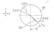
図12において、点Aを揺動ベース285の回転中心の支点(S1)とし、点Bを測定子軸282の傾倒の支点(S2)とし、点Dを測定子281の先端とし、点Cを測定子軸282の軸上で点Dからの垂線が交わる点とする。点Oは、センサユニット250に設定された基準点であり、点Aから測定子281の先端方向上で、回転ベース261の中心軸LOが通る点とする。また、点Aと点Bの距離をa、点Bと点Cの距離をb、点Cと点Dの距離をc、点Bと点Dの距離をdとする。また、この例では、点Oに対する点Aの距離をa/2とする。また、Z方向に対する線分BC(測定子軸282)の角度をα、点Aと点Oを結ぶ方向(H方向)に対する線分ABの角度をβ、線分ABと線分BCの成す角度をγ、Z方向に対する線分BDの角度をφ、線分BDと線分BCのなす角度をτとする。なお、角度βはエンコーダ288により検知される。角度γはエンコーダ286により検知される。
In FIG. 12, point A is the fulcrum (S1) of the center of rotation of the
ここで、点Oに対する点DのH方向(測定子281の先端が向く方向)の位置DhとZ方向の位置Dzは、以下の式で求められる。図12において、点Oに対して右側をH方向のプラス、左側をH方向のマイナス側とし、点Oに対して上側をZ方向のプラス、下側をZ方向のマイナス側とする。
Here, the position Dh in the H direction (the direction in which the tip of the measuring
![]()
![]()
また、角度α、φは、以下により求められる。 Further, the angles α and φ are obtained as follows.

図13は、測定子281の先端方向(H方向)をXY座標系で考えた場合の説明図である。測定ユニット200のXY座標系で点Oを中心にした回転ベース261の回転を考え、Y方向に対する測定子281の先端方向(H方向)の角度をθ(図13上で反時計回りの方向の角度)とすると、点Oを基準とした点Dの位置(x,y,z)は、以下の式で表される。
FIG. 13 is an explanatory diagram when the tip direction (H direction) of the
![]()
![]()
すなわち、センサユニット250に設定された基準位置(点O)に対する測定子281の先端位置は、上記の式4で求められる。センサユニット250に回転ユニット260が設けられた構成においては、角度θはエンコーダ265aにより検知される。図10で示されたように、XY移動ユニットが回転ベース401と水平移動ユニット420により構成され、センサユニット250が回転ユニット260を持たない場合、測定子281の先端方向は、回転ベース401の回転方向とされる。この場合、測定子281の先端方向を変える回転機構として、XY移動ユニットの一部を構成する回転ベース401及びモータ403が使用される。したがって、上記式4の角度θは回転ベース401の回転角により決定される。回転ベース401の回転角は、モータ403の回転駆動の制御データから得られる。
That is, the tip position of the measuring
そして、XY移動ユニット及びZ移動ユニット220により移動されるセンサユニット250の基準位置(点O)は、測定ユニット200に設定されている原点に対する位置(X,Y,Z)として制御される。したがって、測定子281の先端位置は、測定ユニット200の原点に対して、センサユニット250の基準点O(X,Y,Z)と、基準点Oに対する点Dの位置(x,y,z)と、の合成により求められる。
The reference position (point O) of the
次に、測定ユニット200によるレンズ枠の測定動作を説明する。以下では、測定ユニット200の制御方法を理解しやすくするために、レンズ枠の動径方向(XY方向)の測定動作とZ方向の測定動作とに分けて説明する。 Next, the lens frame measurement operation by the measurement unit 200 will be described. Hereinafter, in order to facilitate understanding of the control method of the measurement unit 200, the measurement operation in the radial direction (XY direction) of the lens frame and the measurement operation in the Z direction will be described separately.
レンズ枠の動径方向の測定時、制御部50は、測定済みのレンズ枠の動径情報に基づいてセンサユニット250を移動させるXY位置を決定し、決定したXY位置に従ってXY移動ユニットの駆動を制御する。好ましくは、制御部50は、測定済みのレンズ枠の動径情報に基づいてレンズ枠の未測定部分の動径変化を予測し、未測定部分の動径変化に沿って測定子281の先端が移動するようにセンサユニット250を移動させるXY位置を決定する。例えば、レンズ枠の接線方向に測定子281の先端が移動するように制御する。また、制御部50は、測定済みの動径情報から求められる未測定部分の動径情報に応じて回転ユニット260の回転角を決定し、決定した回転角に従って回転ユニット260の回転を制御する。例えば、制御部50は、測定子281の先端方向がレンズ枠の略法線方向になるように回転ユニット260の回転角を決定する。
When measuring the radial direction of the lens frame, the
図15は、測定子281の移動状態を示す模式図である。図16は、センサユニット250の基準点Oの移動制御及び測定子281の回転方向の制御を説明する図である。なお、動径方向の特徴的な測定動作を説明するために、レンズ枠はZ方向への変化が無いものとする。
FIG. 15 is a schematic diagram showing a moving state of the
図15において、点COは、レンズ枠内に設定された所定点であり、レンズ枠測定時のXYの原点位置とする。点COは、フレーム保持ユニット100により保持されるレンズ枠のY方向の略中心であり、測定開始側のクランプピン130a、130bが位置するY方向上の位置に設定されている。これは、XY移動ユニットが図10に示す回転ベース401の回転中心に相等する位置である。
In FIG. 15, a point CO is a predetermined point set in the lens frame, and is set to the XY origin position at the time of measuring the lens frame. The point CO is substantially the center in the Y direction of the lens frame held by the
図16において、P1、P2、P3、P4、・・・は、点COを基準に動径角を微小角度Δθ毎に変化させたときのレンズ枠FWの測定点を示す。測定点を点COに対して角度Δθ毎に変化する点とすることにより、従来と同じく、測定点の総数を一定として得ることができる。例えば、角度Δθを0.36度とすれば、レンズ枠の動径サイズに拘わりなく、1000点の測定点が得られる。点P1は測定開始点である。 In FIG. 16, P1, P2, P3, P4,... Indicate measurement points of the lens frame FW when the radius vector angle is changed for each minute angle Δθ with respect to the point CO. By making the measurement point a point that changes every angle Δθ with respect to the point CO, the total number of measurement points can be kept constant as in the prior art. For example, if the angle Δθ is 0.36 degrees, 1000 measurement points can be obtained regardless of the radius size of the lens frame. Point P1 is a measurement start point.
測定開始時、制御部50は、退避位置(点CO)に置かれていた測定子281の先端方向(測定子281の先端が向く方向)がY方向(θ1a)となるように回転ユニット260のベース261を回転させ、また、測定子281の先端が測定開始点P1の所定高さ(クランプピン131a,131bのクランプ位置の高さ)に位置させるように、センサユニット250をZ方向に移動させる。次に、制御部50は、XY移動ユニットを駆動し、測定子281の先端をレンズ枠の溝に挿入させる。測定子281の先端がレンズ枠の溝に接触し、その状態からさらにセンサユニット250がレンズ枠側に移動されることにより、垂直状態にあった測定子軸282が支点S2を中心にして傾けられる。測定子軸282が傾けられたことがエンコーダ286の出力変化から検出されるため、測定子281の先端がレンズ枠の溝に接触したことが制御部50により検知される。測定開始点P1では、測定子軸282が図8上の左側に所定角度α1(例えば、5度)だけ傾けられる位置まで、センサユニット250(VHユニット280の基準点O)をレンズ枠側に移動させる。このときの測定子281の先端位置は、XY移動ユニットにより移動されるセンサユニット250のXY位置情報と、エンコーダ286、288の検知情報と、に基づいて得られる。
At the start of measurement, the
なお、測定子281の先端がレンズ枠の溝に接触した後、さらに測定子軸282が角度α1まで傾けられる状態までセンサユニット250を移動させるのは、その後の測定点の測定に際して、基準点Oからの距離が長くなる方向に対しても測定を可能にするためである。本実施形態においては、測定子281は、レンズ枠の溝に挿入された後に支点S2を中心に図8上の左側に傾けられ、バネ291により測定圧が掛けられた状態とされる。この測定圧の発生により、測定子軸282が垂直になるまで、測定子282の先端はレンズ枠の溝位置の変化に追従することができる。
The
次の測定点P2の測定時、測定済みの動径情報は測定点P1の情報のみであるため、制御部50は、X方向と同じ方向Q1(測定点P1の接線方向)と、に方向θ1aに対して微小角度Δθを変化させた方向θ2aと、の交点P2aに次の測定点P2があるものと予測する。そして、制御部50は、方向Q1に対して点P2aでの略法線方向となる角度θ2bを求め、測定子281の先端方向を方向θ2bになるように回転ユニット250を回転する(図16の例では、方向θ2aは測定開始点P1の方向θ1aと同じ角度のままである)と共に、測定子281の先端が点P2aまで移動するように、XY移動ユニットの駆動を制御し、センサユニット250の基準点Oを位置PO1から位置PO2に移動させる。位置PO2の位置は、点P2aの位置、方向θ2b及び距離ΔS(基準点Oから測定子282の先端までを一定距離とするための距離)によって求められる。
At the time of the next measurement point P2, the measured radius vector information is only the information of the measurement point P1, so the
センサユニット250の基準点Oが位置PO2に移動されると、測定子281にはバネ291により所定の測定圧が掛けられているので、測定子281の先端はレンズ枠の実際の位置変化に追従して移動される。測定点P2の位置は、センサユニット250の基準点Oを移動させた位置PO2のXY位置情報と、エンコーダ286,288により得られる測定子281の先端位置D(x、y)の情報(前述の式4)と、に基づいて求められる。
When the reference point O of the
次に、制御部50は、さらに角度Δθだけ変化した方向θ3aに対する測定点P3の位置を、測定済みの点P1,P2の位置情報に基づいて予測する。例えば、測定点P3が近似的に測定済みの点P1,P2を通る直線の延長方向Q2と方向θ3aの方向との交点P3aに位置するものと予測する。また、制御部50は、方向Q2に対して点P3aでの略法線方向となる角度θ3bを求める。そして、制御部50は、測定子281の先端方向を方向θ3bになるように回転ユニット250を回転すると共に、測定子281の先端が点P3aまで移動するように、センサユニット250の基準点Oを位置PO3に移動させる。位置PO3の位置は、点P3aの位置、方向θ3b及び距離ΔSによって求められる。実際の測定点P3の位置は、位置PO3の位置情報と、エンコーダ286,288による検知結果と、に基づいて求められる。
Next, the
同様に、制御部50は、測定済みの測定点P2、P3を通る直線の延長方向Q3と、点P3aに対してさらに角度Δθ分だけ変化した方向θ4aと、に基づいて測定点P4の予測点P4aを求める。次に、方向θ4aに対して測定子281の先端方向が直交する方向θ4bになるように回転ユニット250の回転ベース261の回転角を制御すると共に、点P4aの位置、方向θ4b及び距離ΔSに基づいてセンサユニット250の基準点Oを移動させる位置PO4を決定し、位置PO4に基準点Oが移動するようにXY移動ユニットの駆動を制御することにより、実際の測定点P4の位置を測定する。以後、同様な制御が行われることにより、レンズ枠の全周の動径情報が得られる。
Similarly, the
図15において、レンズ枠FWの内部に示される点線Fdは、センサユニット250の基準点Oの移動軌跡であり、レンズ枠FWの動径形状に略沿った形となっている。このようなセンサユニット250の移動制御により、測定子281の先端を移動させる力PCが働く方向は、レンズ枠FWの動径形状に略沿った方向であるため、レンズ枠FWに対して過大な力が掛らず、レンズ枠FWを変形させずに、測定子281が滑らかに移動されるようになる。
In FIG. 15, a dotted line Fd shown inside the lens frame FW is a movement trajectory of the reference point O of the
また、測定子281の先端方向が未測定分のレンズ枠に対して略法線方向となるように接触するため、測定子281の先端がレンズ枠FWに対して鋭角な角度で接触する場合に比べて、レンズ枠の動径形状を精度良く測定できる。また、レンズ枠の繋ぎ目に段差が生じている場合でも、測定子281の先端が段差を乗り越えやすくなり、レンズ枠の測定不能の不具合を軽減できる。さらに、レンズ枠の反りが大きい場合でも、クランプピンに対して鋭角な角度で測定子281が交わらないため、クランプピンとの干渉を避けた測定が可能になる。
In addition, since the tip of the
またさらに、図18のように、レンズ枠FWの形状が内側に窪んでいる場合でも、測定子281の先端方向がレンズ枠FWの略法線方向になるように移動されるため、窪み部分FWdの測定が可能にされる。レンズ枠FW内に設定された中心COを基準に測定子281の先端方向が向けられる測定方法では、中心COと測定子281の先端方向とを結ぶ直線の延長線に沿うような窪み部分FWdでは、測定子281又は測定子軸282とレンズ枠FWが干渉し、測定が困難になる。上記の制御方法であれば、窪み部分FWdの測定が可能にされる。
Furthermore, as shown in FIG. 18, even when the shape of the lens frame FW is recessed inward, the leading end of the measuring
なお、予測点P2a,P3a,P4a・・・は、点COに対して角度Δθ毎に変化する方向にあるものとして求める代わりに、レンズ枠の動径の変動方向へ微小距離毎に前の測定点から変化した点として求めることでも良い。 In addition, instead of obtaining the predicted points P2a, P3a, P4a,... As if they are in a direction that changes every angle Δθ with respect to the point CO, the previous measurement is performed every minute distance in the direction of variation in the radius of the lens frame. You may obtain | require as a point changed from the point.
次に、測定子281の先端方向の決定に関する変容例を図17により説明する。この変容例は、測定済みの動径情報から求められる未測定部分の動径情報に応じて回転ユニット260の回転角を決定する方法であり、測定子281の先端方向を、中心COを基準とした動径方向と、レンズ枠の法線方向と、の間の方向に決定する方法である。
Next, a modification example regarding the determination of the tip direction of the
図17において、図16と同様な要素には同一符号が付されている。制御部50は、先の例と同じく測定点P2の予測点P2aを求めた後、方向Q1に対する法線方向(直交方向)θ2bと点COを基準とした設定された方向θ2aとの中間方向θ2cを求め、測定子281の先端方向を方向θ2cになるように回転ユニット250を回転する。また、方向θ2c上で、点P2aから距離ΔSだけ離れた位置PO2にセンサユニット250の基準点Oが移動するように、XY移動ユニットの駆動を制御する。
In FIG. 17, the same elements as those in FIG. 16 are denoted by the same reference numerals. The
同様に、制御部50は、次の測定点P3の測定時には、測定済みの測定点P1とP2に通る直線の延長方向Q2と方向θ3aの方向との交点に位置するものとして測定点P3の予測点P3aを求める。次に、点P3aでの方向Q2に対する法線方向θ3bと方向θ3aとの角度の中間方向θ3cを求め、測定子281の先端方向を方向θ3cになるように回転ユニット250を回転する。また、方向θ3c上で、点P3aから距離ΔSだけ離れた位置PO3にセンサユニット250の基準点Oが移動するように、XY移動ユニットの駆動を制御する。以後、同様に、測定済みの動径情報に基づいて次の測定点が位置する点を予測し、その点での法線方向θbと中心点COを基準に角度Δθ毎に変化する動径方向θaとの中間方向θcを求め、この方向θcに測定子281の先端方向が向くように回転ユニット250の回転角を制御すると共に、方向θcと距離ΔSとに基づいてセンサユニット250の基準点Oを移動させる位置を決定し、決定した位置に基づいてXY移動ユニットを制御する。なお、上記の中間方向θcは、比率5:5で分割する中間角度の他、比率6:4で分割する等、法線方向θb側に近い角度であっても良い。
Similarly, when measuring the next measurement point P3, the
この変容例の方法によれば、例えば、図19のように、レンズ枠FWの形状が直角に近く変化している部分FWeを持つ場合でも、測定が可能になる。先の例のように、常に、レンズ枠FWの形状に対して法線方向に測定子281の先端方向が向けられると、直角な変化部分FWeの測定時に測定子軸282がレンズ枠FWに干渉してしまう場合がある。これに対して、測定子281の先端方向を中間方向θcに制御する方法であれば、前述の問題を軽減できる。また、図18のような窪んだ部分を持つレンズ枠の測定にも対応可能であり、レンズ枠を精度良く測定できる。
According to the method of this modification, for example, as shown in FIG. 19, measurement is possible even when the lens frame FW has a portion FWe whose shape is changing at a right angle. As in the previous example, when the tip direction of the
測定子281の先端方向の決定に関しては、上記の以外にも種々変容が可能である。例えば、点COを基準とした動径方向θaに測定子281の先端方向としても良い。この場合でも、レンズ枠のレンズ枠の動径形状に基づいてレンズ枠の未測定部分の形状を予測し、未測定部分の形状に沿って測定子281の先端が移動するように(レンズ枠の接線方向に測定子281の先端が移動する場合を含む)、センサユニット250をXY移動させることにより、レンズ枠に対して過大な力を掛けることなく、レンズ枠の変形を軽減して精度良く測定できる。この方法では、回転ユニット260の回転角の決定に複雑な演算が不要であるので、測定の迅速化が可能になる。また、XY移動ユニットが、図10のように、回転ベース401と水平移動ユニット420により構成されている場合には、センサユニット250に回転ユニット260を設けることなく、レンズ枠の変形を軽減した測定が可能であり、装置構成が簡略化される。
Regarding the determination of the tip direction of the measuring
上記の説明では、レンズ枠の未測定部分の動径変化の予測について、近似的に直前の2点を通る直線としたが、3点以上の測定済みの点によって求めた曲線を使用することでも良い。また、レンズ枠の未測定部分の動径変化の予測には、次の場合も含まれる。例えば、点P2で実際のレンズ枠の動径情報が得られたら、次の点P3の測定に際しては、点P1に対する点P2の動径変化分だけ測定子の先端が移動するように制御する。 In the above description, for the prediction of the radial change of the unmeasured portion of the lens frame, it is assumed that the straight line passes through the two previous points approximately, but it is also possible to use a curve obtained from three or more measured points. good. Moreover, the following cases are also included in the prediction of the radial change of the unmeasured portion of the lens frame. For example, when the actual radius information of the lens frame is obtained at the point P2, when the next point P3 is measured, the tip of the measuring element is controlled to move by the radius change of the point P2 with respect to the point P1.
またさらに、測定点P1と点P2が得られる途中のレンズ枠の測定済みの動径情報に基づいて、測定点P3よりさらに次の測定点P4が位置する予測点を求めてXY移動ユニットを制御し、測定点P2が得られた後に、測定点P4の予測点の位置を補正してXY移動ユニットを駆動制御すると良い。2つ以上前の測定点の動径情報を利用することにより、直前の測定点の測定結果を待って次のXY位置を決定する場合に対して、センサユニット250の移動をスムーズにすることができる。
Further, based on the measured radius information of the lens frame in the middle of obtaining the measurement points P1 and P2, a predicted point where the next measurement point P4 is located further than the measurement point P3 is obtained to control the XY moving unit. Then, after the measurement point P2 is obtained, the position of the predicted point of the measurement point P4 is corrected and the XY moving unit may be driven and controlled. By using the radius vector information of two or more previous measurement points, the movement of the
なお、上記のようなレンズ枠の動径形状の測定においては、センサユニット250をZ方向に移動させるZ移動ユニット220の構成を必ずしも必要とせず、特開2000−314617号等のように、測定子軸282は直動機構によりZ方向の全測定範囲でレンズ枠の溝位置変化に追従して移動可能に保持されている構成でも良い。しかし、レンズ枠に追従する測定子281の滑らかな動きを実現し、より精度良く測定するために、Z方向についてもセンサユニット250が移動される構成が好ましい。さらに、反りの大きな高カーブのレンズ枠の溝から測定子281が外れにくくするために、レンズ枠の反りに合わせて測定子軸282(測定子281)が傾倒される構成が好ましい。
In the measurement of the radial shape of the lens frame as described above, the configuration of the
次に、レンズ枠のZ方向の測定動作を説明する。以下では、高カープフレームを測定する場合にも、測定子281がレンズ枠から外れることを低減し、その測定を精度良く行うための動作を中心に説明する。
Next, the measurement operation of the lens frame in the Z direction will be described. The following description focuses on operations for reducing the detachment of the
レンズ枠の測定時、制御部50は、測定済みのレンズ枠のZ方向の位置に基づいてZ方向移動ユニット220を制御してセンサユニット250をZ方向に移動させる。また、制御部50は、レンズ枠の溝に押し当てられる測定子281の傾斜角がレンズ枠の傾きに沿うように、レンズ枠の測定済みのZ位置に応じてXY移動ユニット(240、230)の移動を制御する。その際、測定済みのレンズ枠の高さ情報に基づいて未測定部分(次の測定点)の高さ変化を予測し、その予測した高さに応じてZ方向の測定子281の傾きがレンズ枠の傾きに沿うように、センサユニット250のXY位置及びZ位置を制御することが好ましい。
When measuring the lens frame, the
図20は、レンズ枠をY方向(XZ方向に垂直な方向)から見たときのレンズ枠FWの反り状態とZ方向の各測定点を示す拡大図である。図21は、Z方向の各測定点の予測点におけるレンズ枠FWの断面と、測定子281及び測定子軸282の傾斜状態を示す図である。なお、センサユニット250(基準点O)のXY方向の移動制御は、説明を簡単にするために、第2の方法(レンズ枠の略法線方向に測定子の先端方向を向ける制御方法)とする。また、図20におけるレンズ枠FWの測定点P1−P4の動径は、X方向の変化のみであり、Y方向に変化が無いものとする。
FIG. 20 is an enlarged view showing a warped state of the lens frame FW and each measurement point in the Z direction when the lens frame is viewed from the Y direction (direction perpendicular to the XZ direction). FIG. 21 is a diagram showing a cross section of the lens frame FW at the predicted point of each measurement point in the Z direction, and the inclination state of the
測定開始点P1の測定時、制御部50は、測定子281の先端方向の角度θをY方向に一致させ、測定子281の先端を測定開始点P1の所定高さに位置させた後、測定子281の先端をレンズ枠の溝に挿入させる。その際、測定子281の先端方向への変動見込み、測定子軸282が移動限界まで達しないように、図21のように、点P1においては、測定子軸282が初期角度α1(例えば、5度)傾けられる位置までセンサユニット250(基準点O)をY方向に移動させる。
When measuring the measurement start point P1, the
続いて、次の測定点P2を測定するために、センサユニット250をXY移動させる。次の測定点P2については、点P1と同じ高さに予測点P2zaがあるものとし、センサユニット250のZ位置は変えず、センサユニット250をXY方向に移動させる。実際の測定点P2の位置は、センサユニット250の基準点Oの位置情報(X,Y,Z)と、エンコーダ286,288の検知結果による検知情報(x,y,z)と、により得られる。点P1から点P2までの距離ΔL2は、点P1と点P2のXY位置に基づいて求められる。このときの予測点P2zaと実際の測定点P2との差をΔz2とする。
Subsequently, the
測定点P2のZ位置が得られたら、測定済みの点P1,P2の位置情報に基づいて次の測定点のZ位置を予測する。例えば、次の測定点P3の予測点P3zaは、距離ΔL3(XY方向の予測点P2a、P3aから求められる)だけ離れた位置で、測定済みの点P1のZ位置と点P2のZ位置と結ぶ延長線方向Qz2上にあるものと予測する。一つ前の予測点P2zaに対する予測点P3zaのZ位置の変位量をΔz3aとする。ΔL2とΔL3を近似的に同距離とすれば、Δz3aは2×Δz2で求められる。また、このときのX軸に対する方向Qz2の角度をρ3とする。角度ρ3は、距離ΔL2と点PのZ位置(Δz2)により得られる(tanρ3=Δz2/ΔL2)。 When the Z position of the measurement point P2 is obtained, the Z position of the next measurement point is predicted based on the position information of the measured points P1 and P2. For example, the predicted point P3za of the next measurement point P3 is connected to the measured Z position of the point P1 and the Z position of the point P2 at a position separated by a distance ΔL3 (obtained from the predicted points P2a and P3a in the XY directions). Predicted to be on the extended line direction Qz2. Let Δz3a be the amount of displacement of the Z position of the prediction point P3za relative to the previous prediction point P2za. If ΔL2 and ΔL3 are approximately the same distance, Δz3a is obtained by 2 × Δz2. Further, the angle of the direction Qz2 with respect to the X axis at this time is represented by ρ3. The angle ρ3 is obtained from the distance ΔL2 and the Z position (Δz2) of the point P (tan ρ3 = Δz2 / ΔL2).
制御部50は、予測点P3aのZ位置に基づいて、Z移動ユニット220のモータ235を駆動し、センサユニット250をZ方向にΔz3a分移動させる。また、レンズ枠の溝はZ位置の変化に応じた反りがあるので、この反りに合わせてレンズ枠の溝に挿入される測定子281の傾斜角度を変化させる。測定子281及び測定子軸282の傾斜角度は、予測点P3zaの角度ρ3に基づいて決定する。点P3zaの測定に際して、Z軸に対して測定子軸282を傾斜させる角度をα3aとする。角度α3aは角度ρ3をそのまま使用しても良いが、実際の測定点P3の上下変動を見込んで、測定点P1を測定するときと同じように、測定子軸282が移動限界まで達しない値を考慮する。例えば、角度α3aは角度ρ3に先の角度α1を加えた値とする。あるいは、角度α3aは角度ρ3にある補正係数kを乗じた値とする。
The
制御部50は、予測点P3zaの位置に測定子281の先端を位置させたときに、測定子軸282が角度α3aだけ傾くように、センサユニット250の点A(基準点O)を測定点P2の位置に対して測定子281の先端方向に移動量Δh3だけ移動させる(図21参照)。移動量Δh3は、角度α3aと、図12に示した点Aと点Bの距離、点Bと点Cの距離、点Cと点Dの距離、点Bと点Dの距離を使用して演算により求められる。
The
図22は、測定子軸282をZ方向に対してある角度Δαだけ傾けるときの、測定子軸282の移動量の求め方を説明する図である。図22では、測定子軸282が垂直状態(Z方向にあるときと、測定子281の先端点Dの位置を変化させず、測定子軸282が垂直状態(Z方向)にあるときの点Aを測定子281の先端方向(H方向)に移動させ、測定子軸282が角度Δαだけ傾斜した状態にあるとき示している。点Aと点Bの距離、点Bと点Cの距離、点Cと点Dの距離、点Bと点Dの距離は、図12と同じく、それぞれ、a、b、c、dとする。測定子軸282が角度Δαだけ傾斜したときの点Aの移動点をA1、点Bの移動点をB1、点Cの移動点をC1とする。また、このときの線分CDと線分BDとの角度をλとし、線分CDと線分B1Dとの角度をωとする。点Dを基準として点Bから点B1への回転角度はΔαとなるので、角度λ、角度ωはそれぞれ以下により求められる。
FIG. 22 is a diagram for explaining how to determine the amount of movement of the tracing
![]()
![]()
![]()
![]()
また、点Dに対する点B1のH方向の距離をDB1h、Z方向の距離をDB1zとすると、DB1h、DB1zはそれぞれ以下の式で求められる。 Further, assuming that the distance in the H direction of the point B1 with respect to the point D is DB1h and the distance in the Z direction is DB1z, DB1h and DB1z can be obtained by the following equations, respectively.
![]()
![]()
![]()
![]()
また、点Bに対する点B1のZ方向の距離をBB1zとすると、BB1zは以下の式で求められる。 Further, assuming that the distance in the Z direction of the point B1 with respect to the point B is BB1z, BB1z can be obtained by the following equation.
![]()
![]()
また、H方向に対する線分BB1の傾斜角をβとすると、βは以下の式で求められる。 Further, when the inclination angle of the line segment BB1 with respect to the H direction is β, β can be obtained by the following equation.
したがって、点Aから点A1の移動量Δhは、図より以下の式で求められる。 Therefore, the movement amount Δh from the point A to the point A1 can be obtained by the following equation from the figure.
この式11において、ω、βについて式10、式6、式5を用いて展開すれば、Δhが既知の距離a、b、c、d、角度Δαにより表わされる。 In Expression 11, when ω and β are expanded using Expression 10, Expression 6, and Expression 5, Δh is expressed by known distances a, b, c, d, and angle Δα.
そして、上記のΔαに対する移動量Δhの演算方法の考え方を基にして角度α3aが決まれば、移動量Δh3も演算により求められる。 If the angle α3a is determined based on the concept of the method for calculating the movement amount Δh with respect to Δα, the movement amount Δh3 can also be obtained by calculation.
図20、図21の説明に戻り、測定子軸282が角度α3aで傾斜されると、測定子281の先端方向も傾斜され、レンズ枠の反りに合うように測定子281の先端がレンズ枠に挿入される。これにより、高カーブフレームの測定時にも測定子281がレンズ枠の溝から外れにくくなる。また、測定を高精度で行える。
Returning to the description of FIG. 20 and FIG. 21, when the
センサユニット250が測定点P2の位置から距離ΔL3だけXY方向に移動されると、実際の測定点P3のXYZ位置が測定される。測定点P2に対する測定点P3のZ位置に変位量をΔz3とする。測定点P3のZ位置が得られたら、測定済みの点P2,P3の位置情報に基づいて次の測定点P4のZ位置を予測する。次の測定点P4の予測点P4zaは、点P3から距離ΔL4だけ離れた位置で、点P2と点P3のZ位置を結ぶ延長線方向Qz3上にあるものと予測する。距離ΔL4は、XY方向の測定点P3と予測点P4aとから求められる。一つ前の予測点P3aに対する予測点P4zaのZ位置の変位量をΔz4aとする。ΔL3とΔL4とが近似的に同一とすれば、Δz4aは、(2×Δz3−Δz2)により求められる。
When the
また、このときのX軸に対する方向Qz3がなす角度をρ4とする。角度ρ4は、距離ΔL3及びΔz3により得られる(tanρ4=Δz3/ΔL3)。 In addition, an angle formed by the direction Qz3 with respect to the X axis at this time is represented by ρ4. The angle ρ4 is obtained by the distances ΔL3 and Δz3 (tan ρ4 = Δz3 / ΔL3).
制御部50は、予測点P4zaの位置に基づいて、一つ前の測定点P3のときにZ方向に移動したときのセンサユニット250の位置に対してZ方向にΔz4a分移動させる(図21参照)。測定点P1を基準にした位置からは、一つ前の測定点P3と測定点P1の差にΔz3を加えた分だけ移動させる。
Based on the position of the predicted point P4za, the
また、予測点P4zaの測定に際して、測定子軸282を傾斜させる角度をα4aとする。角度α4aは、前述と同様に、角度ρ3に先の角度α1を加えた値又は角度ρ3にある補正係数kを乗じた値として決定できる。そして、測定子軸282を角度α4aだけ傾けるように、センサユニット250を測定子281の先端方向(H方向)に移動させるときの移動量Δh4を、前述と同様に求める。そして、求めた移動量Δh4に基づいてセンサユニット250を移動させる。なお、測定子軸282を角度α3a、α4a等に傾斜させるためのセンサユニット250の移動量は、演算で求める他、測定子軸282の傾斜角度を検知するエンコーダ286の出力が角度α3a、α4a等になるまで、センサユニット250をH方向に移動させる制御も可能である。
In addition, when the predicted point P4za is measured, an angle at which the
以後、同様に、制御部50は、測定済みの測定点のZ位置に基づいて次の測定点のZ位置を予測し、予測点に基づいてセンサユニット250をZ方向に移動させる移動量を決定して、Z方向移動ユニット220のモータ225を制御する。また、測定済みの測定点のZ位置に基づいて、レンズ枠の反りに略合致するように測定子281の挿入角度を決定し、その角度に基づいて測定子軸282を傾斜させるべく、XY移動ユニット(240、230)の各モータを制御してセンサユニット250を測定子281の先端方向(H方向)に移動させる。
Thereafter, similarly, the
なお、レンズ枠の測定済みのZ位置変化に基づく未測定部分のZ位置変化の予測は、簡易的には1つ前の測定点との差として決定しても良い。すなわち、測定点P2で実際のレンズ枠のZ位置が得られたら、次の測定点P3の測定に際しては、前の測定点との差(測定点P1とP2との差)のΔz2だけセンサユニット250をZ方向に移動させる。また、測定子軸282のZ方向の変動範囲に余裕を持たせている場合、未測定部分のZ位置変化の予測は、単純に測定済みの最終又は最終付近の測定点でのZ位置と同じとして決定しても良い。測定子軸282の傾斜角度は、測定開始点P1の位置から最後の測定点のZ位置変化(高さ変化)に応じて予め決められた角度に決定しても良い。
The prediction of the Z position change of the unmeasured part based on the measured Z position change of the lens frame may be simply determined as a difference from the previous measurement point. That is, when the actual Z position of the lens frame is obtained at the measurement point P2, when the next measurement point P3 is measured, the sensor unit is equal to Δz2 of the difference from the previous measurement point (difference between the measurement points P1 and P2). 250 is moved in the Z direction. In addition, when the variation range in the Z direction of the
以上のような制御により、高カーブフレームの場合にも、測定子281がレンズ枠の溝から外れることなく測定が行える。また、レンズ枠の溝のZ位置に応じてセンサユニット250をZ方向に移動させ、さらに、測定子281をレンズ枠の溝に挿入するときの傾斜角度もフレームの反りに合うようにセンサユニット250をXY方向に移動させるため、レンズ枠の溝位置に追従する測定子281のZ方向の変動可能範囲を小さくても良い。このため、測定子軸(測定子を持つアーム)の傾倒でZ方向の変動範囲を全てカバーする機構に対して、測定子軸281の長さを短くでき、レンズ枠の溝位置の追従機構であるVHユニット280を軽量化できる。測定子281による追従機構を軽量化できれば、測定子281のより滑らかな動きが可能になるため、測定を高精度で行える。
By the control as described above, even in the case of a high curve frame, measurement can be performed without the
なお、測定子281のZ方向の追従範囲は余裕を持たせてあり、また、測定子281をレンズ枠の溝に挿入するときの傾斜角度もフレームの反りにほぼ沿えばよい。このため、センサユニット250のZ方向の位置制御及び測定子軸282の傾斜角度の制御は、上記のようにセンサユニット250をXY方向の次の測定点に移動する毎に行わなくても、例えば、3点又は5点の測定点の間隔をおいて行うようにしても良い。
The tracking range of the measuring
図20、図21等においては、Z方向の測定動作を理解しやすく簡単にするために、レンズ枠の各測定点P1,P2,P3,P4はY方向の変動が無いものとしたが、実際の測定においては、レンズ枠の動径形状を測定するときのXY制御と組み合わされて制御される。すなわち、レンズ枠の測定済みの動径形状に基づいて決定されるセンサユニット250のXY位置に対して、さらに上記のように測定子軸282を傾斜させるために必要なXY位置の変化分が加えられる。
In FIG. 20, FIG. 21, etc., in order to make the measurement operation in the Z direction easy to understand and easy, the measurement points P1, P2, P3, and P4 of the lens frame are assumed to have no variation in the Y direction. This measurement is controlled in combination with XY control when measuring the radial shape of the lens frame. That is, the change in the XY position necessary for tilting the
測定されたレンズ枠の三次元形状のデータは、制御部50が持つメモリに記憶される。片方のレンズ枠の測定が終了すると、センサユニット250は、初期位置に後退された後、退避位置まで下降され、もう片方のレンズ枠の初期位置までX方向に移動される。その後は、同様な制御によりもう片方のレンズ枠の三次元形状が測定される。
The measured data of the three-dimensional shape of the lens frame is stored in a memory included in the
なお、上記で説明したレンズ枠のZ方向の形状を精度良く測定するための構成及び制御に関しては、前述したレンズ枠の動径形状の測定機構及び制御は必ずしも必要なく、レンズ枠の動径形状の測定機構及び制御は従前と同様であっても良い。 Regarding the configuration and control for accurately measuring the shape of the lens frame in the Z direction described above, the above-described measurement mechanism and control of the radial shape of the lens frame are not necessarily required. The measurement mechanism and control may be the same as before.
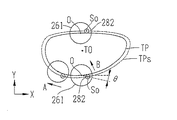
次に、型板TPの測定動作を説明する。図23は、型板TPの測定時において、測定子軸282の中心Soと、センサユニット250の基準点Oの移動状態を模式的に示した図である。型板ホルダ310に取り付けられた型板TPは、取り付け部300によってXY平面に平行な状態で、ベースユニット210の中央位置に置かれる。
Next, the measurement operation of the template TP will be described. FIG. 23 is a diagram schematically showing the movement state of the center So of the tracing
制御部50は、型板TPのXY方向(動径情報)の測定に際して、測定された型板TPの動径情報に基づいてXY移動ユニットを制御してセンサユニット250をXY方向に移動させる。その際、好ましくは、制御部50は、測定済みの型板TPの動径情報に基づいて未測定部分の動径変化を予測し、その予測した動径変化に応じてセンサユニット250をXY方向に移動させる。型板TPの動径情報は、センサユニット250のXY方向の移動情報と、型板TPの動径変化に追従して変化する回転ベース261の回転角の検出情報と、に基づいて得られる。
When measuring the XY direction (radial radius information) of the template TP, the
図23において、制御部50は、型板測定開始信号が入力されると、測定開始時に型板TPの取り付け中心TOのY方向で型板TPから離れた所定位置にセンサユニット250の基準点Oを位置させ、測定子軸282のZ方向の中心部が型板TPの高さに位置するように、Z移動ユニット220を制御して退避高さに置かれた測定子軸282を上昇させる。このとき、測定子281の先端方向がX軸を平行になるように、回転ベース261を回転させるモータ265を制御する。
In FIG. 23, when the template measurement start signal is input, the
その後、センサユニット250の中心Oが型板TPの中心TOに向かうように、センサユニット250をY方向に移動させる。測定子軸282が型板TPの周縁に接触された後、さらにセンサユニット250がY方向に移動されると、測定子軸282は型板TPとの接触位置よりY方向へ移動できないため、回転ベース261がその中心軸LO(基準点O)を中心にして回転される。回転ベース261の回転角の変化がエンコーダ265aにより検出されることにより、測定子軸282の型板TPへの接触が検知される。制御部50は、測定子軸282の先端方向の回転角θ(ここでは、回転角θはX方向に対する角度として説明する)が、ある角度θa(例えば、5度)となるまで、センサユニット250のY方向に移動させる。そして、制御部50は、このときに測定子軸282の中心点Soが位置する点P1を、測定開始時の測定点として得る。このときの点P1のXY座標位置は、図24に示されるように、回転ベース261の回転中心である基準点OのXY移動の座標位置(X、Y)と、基準点Oに対する測定子軸282の中心点Soのxy座標(x1,y1)から得られる。基準点Oに対する点Soのxy座標(x1,y1)は、点Oと中心点Osとの距離Rs(これは設計的に既知である)と、X軸に対する回転角θ1(測定点P1ではθa)とにより三角関数の計算により求められる。
Thereafter, the
次に、制御部50は、次の測定点を測定するために、レンズ枠の動径情報の測定時と同様に、測定済みの測定点に基づいて微小角度Δθ(中心TOを基準にした回転角)の回転に対応する距離だけ、センサユニット250(基準点O)をXY方向に移動させる。なお、型板測定では、測定子281の先端方向とは逆方向である矢印A方向(図23上)に移動させる。測定開始点P1に続く測定点P2(図21では、図示を省く)の測定では、X方向と平行な方向に測定点P2があるものとして、X方向に移動させる。この移動に伴って、型板TPの動径がY方向に変動していれば、モータ265により与えられる測定圧により測定子軸282がその変動に追従し、基準点Oを中心に測定子軸282の中心点Soが回転される。なお、測定開始点P1以降の測定においては、回転ベース261は図22上の矢印B方向(点Oを中心に反時計回りの方向)に常時測定圧が掛けられるように、モータ265が制御されている。
Next, in order to measure the next measurement point, the
図24において、次の測定点P2が測定されたときの中心点Soの回転角をθ2とすると、基準点Oに対する中心点Soの座標(x2,y2)は、距離Rsと回転角θ2とにより求められる。そして、制御部50は、この測定済みの点P1,P2に基づいて次の測定点P3を測定するためのセンサユニット250のXY移動位置を決定する。例えば、点P1に対する点P2のXY方向の変動量(Δx2,Δy2)を求め、次の測定点を測定するためにセンサユニット250を移動する際に、変動量(Δx2,Δy2)を補正した位置に移動させる。以後、これを繰り返すことにより、全周の測定点の位置情報が得られるが、好ましくは、レンズ枠の場合と同様に、測定済みの点P1と点P2とを結ぶ直線の延長線方向に次の測定点P3があるものと予測し、センサユニット250の基準点Oを移動させる。基準点Oを移動させたときのセンサユニット250のXY移動情報と、中心点Soが型板TPの動径変動に追従して回転された角度(θ3)とに基づいて、実際の測定点P3の位置が求められる。次の測定点P4の測定に際しては、測定済みの点P2、P3を基に測定点4の位置する方向を予測し(又は3個以上の測定済み点から曲線を形状として予測することができる)、予測した点に測定子軸282が移動するようにセンサユニット250の基準点Oを移動させる。以後、同様な方法により、未測定部分の測定点を予測してセンサユニット250をXY方向に移動させ、全周の測定点の情報を得る。
In FIG. 24, when the rotation angle of the center point So when the next measurement point P2 is measured is θ2, the coordinates (x2, y2) of the center point So with respect to the reference point O are expressed by the distance Rs and the rotation angle θ2. Desired. Then, the
なお、測定子軸282の中心点Soで得られ測定点を結んだ動径形状TPsは、型板TPの動径形状よりも測定子軸282の半径rs分だけ一回り大きな形状として得られる。実際の型板TPの動径形状は、動径形状TPsに対して半径rsの距離分だけ内側に小さい相似形として演算される。
The radial shape TPs obtained at the center point So of the tracing
以上のような方法により、センサユニット250をXY移動させる構成を持つ測定ユニット200において、型板TPの形状測定が測定子軸282を用いて可能になる。
By the method as described above, in the measurement unit 200 having a configuration in which the
測定子軸282を使用した型板測定方法としては、上記に限らず、種々の方法がある。例えば、測定子軸282の前側(図8上の右側であり、測定子281の先端側)又は後側(図8上の左側)に型板TPとの接触部を持つように構成する。型板TPの測定時には、制御部50は、測定子軸282が図8上の左側に所定角度(例えば、5度)傾けられた状態で、接触部が垂直(Z方向に平行な面)を維持して型板TPに接触するように、測定済みの型板TPの動径位置に基づき、レンズ枠の動径測定と同様な制御方法により、センサユニット250のXY位置及び回転ユニット260の回転を制御する。測定子軸282を型板TPに押し当てる測定圧は、バネ291の付勢力によって与えられる。なお、測定子軸282が傾斜されずに、測定子軸282が垂直(Z軸に平行)な状態で水平方向に移動される構成においては、型板TPとの接触部は測定子軸282の側面(測定子281の先端側又は後側)とされる。
The template measuring method using the
1 玉型形状測定装置
50 制御部
100 フレーム保持ユニット
200 測定ユニット
210 移動ユニット
220 Z移動ユニット
230 Y移動ユニット
240 X移動ユニット
250 センサユニット
260 回転ユニット
280 保持ユニット
281 測定子
282 測定子軸
285 揺動ベース
286、288 エンコーダ
291 バネ
S1 軸
S2 軸
DESCRIPTION OF
Claims (3)
前記測定子が上部に取り付けられた測定子軸を持つ測定子保持ユニットであって、前記測定子軸のZ方向の位置を自由に移動可能に保持すると共に、前記測定子の先端方向に前記測定子軸を移動可能に保持し、且つ前記測定子の先端をレンズ枠の溝に押し当てる測定圧を付与する測定圧付与機構と、動径方向における前記測定子の先端の向きを変えるために、前記測定子軸をZ方向に設定された軸を中心に回転する回転手段と、が設けられた測定子保持ユニットと、
前記測定子保持ユニットを動径方向に2次元的に移動させる動径方向移動手段と、
前記測定子の動径方向の位置を検知する動径検知手段であって、前記測定子保持ユニットの動径方向の位置を検知する第1動径検知手段と、前記測定子保持ユニットに対する前記測定子の動径方向の位置を検知する第2動径検知手段と、を持つ動径検知手段と、
測定開始後に得られた前記動径検知手段の検知結果に基づいて次の測定位置における前記回転手段の回転角及び前記測定子保持ユニットの動径位置を得て、得られた結果に基づいて前記回転手段及び動径方向移動手段の動作を制御する制御手段と、
を備えることを特徴とする眼鏡枠形状測定装置。 A spectacle frame holding unit that holds the spectacle frame in an expected state; and a measuring element having a needle-like tip shape that is inserted into and pressed against a groove of the lens frame of the spectacle frame, and the moving position of the measuring element In the spectacle frame shape measuring apparatus for measuring the three-dimensional shape of the lens frame held in the spectacle frame holding unit in the radial direction (XY direction) and the direction perpendicular to the radial direction (Z direction),
A measuring element holding unit having a measuring element shaft attached to an upper part of the measuring element, and holding the position of the measuring element axis in the Z direction so as to be freely movable, and measuring the measuring element in a tip direction of the measuring element. In order to change the direction of the tip of the measuring element in the radial direction, and a measuring pressure applying mechanism that applies a measuring pressure that holds the element shaft movably and presses the tip of the measuring element against the groove of the lens frame , A probe holding unit provided with rotation means for rotating the probe axis around an axis set in the Z direction ;
A radial moving means for moving the probe holding unit two-dimensionally in the radial direction;
Radial radius detection means for detecting a radial position of the probe, the first radial detection means for detecting the radial position of the measurement element holding unit, and the measurement with respect to the measurement element holding unit. A second radial detection means for detecting the radial position of the child, and a radial detection means having
Based on the detection result of the radial detection means obtained after the start of measurement, obtain the rotation angle of the rotation means and the radial position of the probe holding unit at the next measurement position, and based on the obtained results Control means for controlling the operation of the rotation means and the radial movement means;
An eyeglass frame shape measuring apparatus comprising:
Priority Applications (3)
| Application Number | Priority Date | Filing Date | Title |
|---|---|---|---|
| JP2009279943A JP5586930B2 (en) | 2009-12-09 | 2009-12-09 | Eyeglass frame shape measuring device |
| US12/963,081 US8578617B2 (en) | 2009-12-09 | 2010-12-08 | Eyeglass frame shape measurement apparatus |
| EP10015495.4A EP2335874B1 (en) | 2009-12-09 | 2010-12-09 | Eyeglass frame shape measurement apparatus |
Applications Claiming Priority (1)
| Application Number | Priority Date | Filing Date | Title |
|---|---|---|---|
| JP2009279943A JP5586930B2 (en) | 2009-12-09 | 2009-12-09 | Eyeglass frame shape measuring device |
Publications (3)
| Publication Number | Publication Date |
|---|---|
| JP2011122899A JP2011122899A (en) | 2011-06-23 |
| JP2011122899A5 JP2011122899A5 (en) | 2013-01-24 |
| JP5586930B2 true JP5586930B2 (en) | 2014-09-10 |
Family
ID=43480944
Family Applications (1)
| Application Number | Title | Priority Date | Filing Date |
|---|---|---|---|
| JP2009279943A Active JP5586930B2 (en) | 2009-12-09 | 2009-12-09 | Eyeglass frame shape measuring device |
Country Status (3)
| Country | Link |
|---|---|
| US (1) | US8578617B2 (en) |
| EP (1) | EP2335874B1 (en) |
| JP (1) | JP5586930B2 (en) |
Families Citing this family (10)
| Publication number | Priority date | Publication date | Assignee | Title |
|---|---|---|---|---|
| KR101952447B1 (en) * | 2011-09-21 | 2019-02-26 | 가부시키가이샤 니데크 | Device for measuring the shape of eyeglasses frame |
| JP5817379B2 (en) * | 2011-09-21 | 2015-11-18 | 株式会社ニデック | Eyeglass frame shape measuring device |
| KR101917394B1 (en) | 2011-09-21 | 2018-11-09 | 가부시키가이샤 니데크 | Device for measuring the shape of eyeglasses frame |
| JP5983139B2 (en) * | 2012-07-23 | 2016-08-31 | 株式会社ニデック | Eyeglass frame shape measuring device |
| JP6172430B2 (en) | 2012-09-05 | 2017-08-02 | 株式会社ニデック | Eyeglass frame shape measuring device |
| WO2019049715A1 (en) * | 2017-09-05 | 2019-03-14 | 株式会社ニデック | Eyeglass frame shape measurement device and eyeglass frame shape measurement program |
| WO2019163723A1 (en) * | 2018-02-22 | 2019-08-29 | 株式会社ニデック | Lens shape acquisition device |
| JP7517045B2 (en) | 2020-09-30 | 2024-07-17 | 株式会社ニデック | Eyeglass frame shape measuring device and control program for eyeglass frame shape measuring device |
| EP3978863A1 (en) | 2020-09-30 | 2022-04-06 | Nidek Co., Ltd. | Eyeglass frame shape measurement apparatus and control program for eyeglass frame shape measurement apparatus |
| JP7084062B1 (en) | 2021-04-14 | 2022-06-14 | 株式会社タクボ精機製作所 | Eyeglass frame shape measuring device |
Family Cites Families (17)
| Publication number | Priority date | Publication date | Assignee | Title |
|---|---|---|---|---|
| FR2614690B1 (en) | 1987-04-28 | 1990-11-09 | Essilor Int | CONTOUR READING APPARATUS, PARTICULARLY FOR EYEWEAR MOUNTING |
| US5450335A (en) * | 1992-08-05 | 1995-09-12 | Hoya Corporation | Method of processing spectacle frame shape data |
| JP3778726B2 (en) | 1999-05-01 | 2006-05-24 | 株式会社ニデック | Template holder |
| ES2327891T3 (en) | 1999-04-30 | 2009-11-05 | Nidek Co., Ltd. | TEMPLATE SUPPORT, A WISHED LENS MEASURING DEVICE THAT INCLUDES THIS SUPPORT, AND A GLASS LENS PROCESSING DEVICE THAT HAS THIS DEVICE. |
| JP3695988B2 (en) | 1999-04-30 | 2005-09-14 | 株式会社ニデック | Eyeglass frame shape measuring device |
| CA2283495A1 (en) | 1999-09-23 | 2001-03-23 | Elision Technology Inc. | Eyeglass frame and lens tracing apparatus and method |
| JP4588828B2 (en) | 1999-12-22 | 2010-12-01 | 株式会社トプコン | Eyeglass shape measuring device for glasses |
| JP2004003944A (en) * | 2002-04-08 | 2004-01-08 | Hoya Corp | Instrument for measuring shape of spectacl eframe |
| US6901677B2 (en) | 2003-05-05 | 2005-06-07 | University Of North Carolina At Charlotte | Method and apparatus using a closed loop controlled actuator for surface profilometry |
| US7140119B2 (en) | 2004-04-23 | 2006-11-28 | Corning Incorporated | Measurement of form of spherical and near-spherical optical surfaces |
| FR2870934B1 (en) * | 2004-05-28 | 2006-09-08 | Essilor Int | CONTOUR READING APPARATUS COMPRISING A ROTATING MOBILE PROBE |
| SE527907C2 (en) | 2004-09-30 | 2006-07-04 | Dynamate Ab | Device and method for measuring in machine tools |
| JP4920514B2 (en) | 2007-07-04 | 2012-04-18 | 株式会社ニデック | Ball shape measuring device |
| JP5259145B2 (en) * | 2007-09-11 | 2013-08-07 | 株式会社ニデック | Lens frame shape measuring device |
| JP5259144B2 (en) * | 2007-09-11 | 2013-08-07 | 株式会社ニデック | Lens frame shape measuring device |
| FR2925963B1 (en) | 2008-01-02 | 2010-08-13 | Briot Int | APPARATUS FOR PALPING AN OPTICAL GLASS MOUNT AND ASSOCIATED METHOD |
| JP5562624B2 (en) * | 2009-12-09 | 2014-07-30 | 株式会社ニデック | Eyeglass frame shape measuring device |
-
2009
- 2009-12-09 JP JP2009279943A patent/JP5586930B2/en active Active
-
2010
- 2010-12-08 US US12/963,081 patent/US8578617B2/en active Active
- 2010-12-09 EP EP10015495.4A patent/EP2335874B1/en active Active
Also Published As
| Publication number | Publication date |
|---|---|
| EP2335874B1 (en) | 2019-02-20 |
| US8578617B2 (en) | 2013-11-12 |
| JP2011122899A (en) | 2011-06-23 |
| US20110131822A1 (en) | 2011-06-09 |
| EP2335874A1 (en) | 2011-06-22 |
Similar Documents
| Publication | Publication Date | Title |
|---|---|---|
| JP5562624B2 (en) | Eyeglass frame shape measuring device | |
| JP5586930B2 (en) | Eyeglass frame shape measuring device | |
| JP4920514B2 (en) | Ball shape measuring device | |
| EP2312263B1 (en) | Offset Amount Calibrating Method and Surface Profile Measuring Machine | |
| JP2015163407A (en) | Welding torch detection device, and welding robot system | |
| JP6080002B2 (en) | Eyeglass lens processing equipment | |
| JP2014081324A (en) | Surface roughness measurement unit and three-dimensional measurement device | |
| JP6172430B2 (en) | Eyeglass frame shape measuring device | |
| WO2018150178A1 (en) | Surface finish or surface roughness probe | |
| JP4570437B2 (en) | Surface roughness / contour shape measuring device | |
| JP2021094600A (en) | Machine tool and shape measurement method of workpiece machining part | |
| JP2021092531A (en) | Measurement device and measurement method | |
| WO2019155698A1 (en) | Surface shape measurement device | |
| JP2005221422A (en) | Gear measuring machine | |
| JP2002022433A (en) | Sensor and equipment for measuring work shape | |
| JP2022057965A (en) | Spectacle frame shape measurement device and control program of spectacle frame shape measurement device | |
| JP4652011B2 (en) | Three-dimensional coordinate measurement system and part program used therefor | |
| US9144876B2 (en) | Eyeglass lens processing apparatus | |
| JP5850310B2 (en) | Eyeglass frame shape measuring device | |
| JP2013068488A (en) | Glass frame shape measuring apparatus | |
| JP7038308B2 (en) | Surface shape measuring machine | |
| JP7243706B2 (en) | Lens shape acquisition device | |
| JP6319627B2 (en) | Eyeglass lens peripheral shape measuring apparatus and spectacle lens peripheral shape measuring method | |
| JPH10286745A (en) | Work measurement method for nc machine tool | |
| JP2022057964A (en) | Spectacle frame shape measurement device and control program of spectacle frame shape measurement device |
Legal Events
| Date | Code | Title | Description |
|---|---|---|---|
| A521 | Request for written amendment filed |
Free format text: JAPANESE INTERMEDIATE CODE: A523 Effective date: 20121130 |
|
| A621 | Written request for application examination |
Free format text: JAPANESE INTERMEDIATE CODE: A621 Effective date: 20121130 |
|
| A977 | Report on retrieval |
Free format text: JAPANESE INTERMEDIATE CODE: A971007 Effective date: 20130725 |
|
| A131 | Notification of reasons for refusal |
Free format text: JAPANESE INTERMEDIATE CODE: A131 Effective date: 20130806 |
|
| A521 | Request for written amendment filed |
Free format text: JAPANESE INTERMEDIATE CODE: A523 Effective date: 20131007 |
|
| TRDD | Decision of grant or rejection written | ||
| A01 | Written decision to grant a patent or to grant a registration (utility model) |
Free format text: JAPANESE INTERMEDIATE CODE: A01 Effective date: 20140701 |
|
| A61 | First payment of annual fees (during grant procedure) |
Free format text: JAPANESE INTERMEDIATE CODE: A61 Effective date: 20140723 |
|
| R150 | Certificate of patent or registration of utility model |
Ref document number: 5586930 Country of ref document: JP Free format text: JAPANESE INTERMEDIATE CODE: R150 |
|
| R250 | Receipt of annual fees |
Free format text: JAPANESE INTERMEDIATE CODE: R250 |
|
| R250 | Receipt of annual fees |
Free format text: JAPANESE INTERMEDIATE CODE: R250 |
|
| R250 | Receipt of annual fees |
Free format text: JAPANESE INTERMEDIATE CODE: R250 |
|
| R250 | Receipt of annual fees |
Free format text: JAPANESE INTERMEDIATE CODE: R250 |
|
| R250 | Receipt of annual fees |
Free format text: JAPANESE INTERMEDIATE CODE: R250 |
|
| R250 | Receipt of annual fees |
Free format text: JAPANESE INTERMEDIATE CODE: R250 |
|
| R250 | Receipt of annual fees |
Free format text: JAPANESE INTERMEDIATE CODE: R250 |
|
| R250 | Receipt of annual fees |
Free format text: JAPANESE INTERMEDIATE CODE: R250 |