JP3695988B2 - Eyeglass frame shape measuring device - Google Patents
Eyeglass frame shape measuring device Download PDFInfo
- Publication number
- JP3695988B2 JP3695988B2 JP12539599A JP12539599A JP3695988B2 JP 3695988 B2 JP3695988 B2 JP 3695988B2 JP 12539599 A JP12539599 A JP 12539599A JP 12539599 A JP12539599 A JP 12539599A JP 3695988 B2 JP3695988 B2 JP 3695988B2
- Authority
- JP
- Japan
- Prior art keywords
- frame
- measuring
- spectacle frame
- lens
- moving
- Prior art date
- Legal status (The legal status is an assumption and is not a legal conclusion. Google has not performed a legal analysis and makes no representation as to the accuracy of the status listed.)
- Expired - Fee Related
Links
Images


Classifications
-
- B—PERFORMING OPERATIONS; TRANSPORTING
- B24—GRINDING; POLISHING
- B24B—MACHINES, DEVICES, OR PROCESSES FOR GRINDING OR POLISHING; DRESSING OR CONDITIONING OF ABRADING SURFACES; FEEDING OF GRINDING, POLISHING, OR LAPPING AGENTS
- B24B17/00—Special adaptations of machines or devices for grinding controlled by patterns, drawings, magnetic tapes or the like; Accessories therefor
- B24B17/02—Special adaptations of machines or devices for grinding controlled by patterns, drawings, magnetic tapes or the like; Accessories therefor involving mechanical transmission means only
- B24B17/025—Special adaptations of machines or devices for grinding controlled by patterns, drawings, magnetic tapes or the like; Accessories therefor involving mechanical transmission means only for grinding rotating workpieces (three dimensional)
- B24B17/026—Special adaptations of machines or devices for grinding controlled by patterns, drawings, magnetic tapes or the like; Accessories therefor involving mechanical transmission means only for grinding rotating workpieces (three dimensional) for the periphery of plane workpieces, e.g. cams, lenses
-
- B—PERFORMING OPERATIONS; TRANSPORTING
- B23—MACHINE TOOLS; METAL-WORKING NOT OTHERWISE PROVIDED FOR
- B23Q—DETAILS, COMPONENTS, OR ACCESSORIES FOR MACHINE TOOLS, e.g. ARRANGEMENTS FOR COPYING OR CONTROLLING; MACHINE TOOLS IN GENERAL CHARACTERISED BY THE CONSTRUCTION OF PARTICULAR DETAILS OR COMPONENTS; COMBINATIONS OR ASSOCIATIONS OF METAL-WORKING MACHINES, NOT DIRECTED TO A PARTICULAR RESULT
- B23Q3/00—Devices holding, supporting, or positioning work or tools, of a kind normally removable from the machine
- B23Q3/18—Devices holding, supporting, or positioning work or tools, of a kind normally removable from the machine for positioning only
-
- B—PERFORMING OPERATIONS; TRANSPORTING
- B24—GRINDING; POLISHING
- B24B—MACHINES, DEVICES, OR PROCESSES FOR GRINDING OR POLISHING; DRESSING OR CONDITIONING OF ABRADING SURFACES; FEEDING OF GRINDING, POLISHING, OR LAPPING AGENTS
- B24B9/00—Machines or devices designed for grinding edges or bevels on work or for removing burrs; Accessories therefor
- B24B9/02—Machines or devices designed for grinding edges or bevels on work or for removing burrs; Accessories therefor characterised by a special design with respect to properties of materials specific to articles to be ground
- B24B9/06—Machines or devices designed for grinding edges or bevels on work or for removing burrs; Accessories therefor characterised by a special design with respect to properties of materials specific to articles to be ground of non-metallic inorganic material, e.g. stone, ceramics, porcelain
- B24B9/08—Machines or devices designed for grinding edges or bevels on work or for removing burrs; Accessories therefor characterised by a special design with respect to properties of materials specific to articles to be ground of non-metallic inorganic material, e.g. stone, ceramics, porcelain of glass
- B24B9/14—Machines or devices designed for grinding edges or bevels on work or for removing burrs; Accessories therefor characterised by a special design with respect to properties of materials specific to articles to be ground of non-metallic inorganic material, e.g. stone, ceramics, porcelain of glass of optical work, e.g. lenses, prisms
- B24B9/148—Machines or devices designed for grinding edges or bevels on work or for removing burrs; Accessories therefor characterised by a special design with respect to properties of materials specific to articles to be ground of non-metallic inorganic material, e.g. stone, ceramics, porcelain of glass of optical work, e.g. lenses, prisms electrically, e.g. numerically, controlled
-
- G—PHYSICS
- G01—MEASURING; TESTING
- G01B—MEASURING LENGTH, THICKNESS OR SIMILAR LINEAR DIMENSIONS; MEASURING ANGLES; MEASURING AREAS; MEASURING IRREGULARITIES OF SURFACES OR CONTOURS
- G01B5/00—Measuring arrangements characterised by the use of mechanical techniques
- G01B5/20—Measuring arrangements characterised by the use of mechanical techniques for measuring contours or curvatures
-
- G—PHYSICS
- G02—OPTICS
- G02C—SPECTACLES; SUNGLASSES OR GOGGLES INSOFAR AS THEY HAVE THE SAME FEATURES AS SPECTACLES; CONTACT LENSES
- G02C13/00—Assembling; Repairing; Cleaning
- G02C13/003—Measuring during assembly or fitting of spectacles
Abstract
Description
【0001】
【発明の属する技術分野】
本発明は、眼鏡枠又は型板等の玉型の形状を測定するための眼鏡枠形状測定装置及びこれを有する眼鏡レンズ加工装置に関する。
【0002】
【従来技術】
眼鏡枠形状測定装置としては、特開平4−18516号公報に記載されているように、フレーム保持部により保持された眼鏡枠の枠溝に測定子を押圧させながら当接させ、測定子を枠溝に沿って移動させることにより、その移動情報から眼鏡枠の玉型形状を測定するものが知られている。従来のこの種の装置では、測定子を枠溝に当接させる際には、バネの付勢力によって枠溝側(玉型形状の動径方向側)に押圧して測定していた。
【0003】
【発明が解決しようとする課題】
しかしながら、従来の眼鏡枠形状測定装置には次のような問題があった。
【0004】
(1) バネを利用した測定子の押圧の方法は、眼鏡枠の動径に応じてバネが伸び縮みするので、測定中の眼鏡枠に対する押圧力は一定ではない。様々な形状の眼鏡枠にも対応できるように、かつ測定中に枠溝から測定子が外れないようにするためには、バネが縮んだ状態(動径長が長い部分)においてもある程度の力が加わるようにする必要がある。こうして決定されたバネの力で測定を行うと、動径長が短い部分では大きな押圧力がフレームに対して掛かるようになり、材質的に又は構造的に柔らかい眼鏡枠の場合には変形を生じる虞がある。眼鏡枠を変形させずに測定するためには、測定子が外れない程度の弱い押圧力で、かつできるだけ一定の押圧力が枠溝に掛かるようにすることが好ましい。
【0005】
(2) また、バネを利用した測定子の押圧の方法では、フレーム保持部による眼鏡枠の保持及び測定子の移動機構部を傾斜させずにほぼ水平に保つ必要があり、装置の配置に自由度がなかった。すなわち、測定子の移動機構が傾斜していると、その自重の影響で測定する動径の角度方向によって測定子の押圧力が異なり、眼鏡枠の変形や枠溝から測定子が外れる可能性が大きくなる。
【0006】
(3) 測定子を眼鏡枠の枠溝に挿入した後は、一般に測定子は枠溝に沿って上下移動するようにフリーな状態されていたので、反りが大きな眼鏡枠の場合には測定子が外れやすかった。
【0007】
本発明は、上記従来技術の問題点に鑑み、眼鏡枠の変形の虞を低減し、また、測定子が眼鏡枠溝から外れることなく測定を行える眼鏡枠測定装置及びこれを有する眼鏡レンズ加工装置を提供することを技術課題とする。
【0008】
また、装置の配置の自由度が高い眼鏡枠測定装置及びこれを有する眼鏡レンズ加工装置を提供することを技術課題とする。
【0009】
【課題を解決するための手段】
上記課題を解決するために、本発明は以下のような構成を備えることを特徴とする。
【0010】
(1) 眼鏡枠を保持手段により所期する状態に保持し、眼鏡枠の枠溝に測定子を当接させつつ、枠溝に沿って移動させて、測定子の三元的な移動を検出手段により検出することにより、眼鏡枠の玉型形状を測定する眼鏡枠形状測定装置において、前記測定子を眼鏡枠の動径方向へ移動するための駆動モータと、前記検出手段より測定済みの動径情報の変化に基づいて、未測定部分の動径変動を予測し、その予測した動径変動に応じて前記駆動モータの駆動を制御する制御手段と、を備えることを特徴とする。
(2) (1)の眼鏡枠形状測定装置において、さらに前記測定子を前記動径方向と直交する第2方向に移動するための第2駆動モータと、前記測定子の第2方向への移動情報を得る測定手段と、該測定手段により得られる結果に基づいて測定途中の前記第2駆動モータの駆動を制御する第2制御手段と、を備えるとともに、該第2制御手段は、前記測定手段により得られる測定済みの前記第2方向における変動情報を基に未測定部分の第2方向における変動を予測し、その予測した変動に応じて前記測定子を移動するように前記第2駆動モータを駆動制御することを特徴とする。
(3) 眼鏡枠をクランプピンにより測定基準平面に保持し、眼鏡枠の枠溝に測定子を当接させつつ、枠溝に沿って移動させて、測定子の三元的な移動を検出手段により検出することにより、眼鏡枠の玉型形状を測定する眼鏡枠形状測定装置において、設置水平面に対して前記測定基準平面を所定の角度傾斜させて眼鏡枠をクランプする眼鏡枠保持手段と、前記測定子を測定基準平面と平行な眼鏡枠の動径方向へ移動するための駆動モータと、測定基準平面が傾斜していることによりかかる荷重分をキャンセルするように前記駆動モータの駆動を制御する制御手段と、を備えることを特徴とする。
【0017】
【発明の実施の形態】
以下、本発明の実施の形態を図面に基づいて説明する。
【0018】
(1)全体構成
図1は本発明に係る眼鏡レンズ加工装置の外観構成を示す図である。装置本体1の上部右奥には、眼鏡枠測定装置2が内蔵されている。眼鏡枠測定装置2は装置本体1の筐体上面の傾斜に沿って手前側に傾斜して配置されており、後述するフレーム保持部200への眼鏡枠のセットが行い易くなっている。眼鏡枠測定装置2の前方には、眼鏡枠測定装置2を操作するためのスイッチを持つスイッチパネル部410、加工情報等を表示するディスプレイ415が配置されている。また、420は加工条件等の入力や加工のための指示を行う各種のスイッチを持つスイッチパネル部であり、402は加工室用の開閉窓である。
【0019】
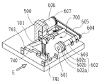
図2は装置本体1の筐体内に配置される加工部の構成を示す斜視図である。ベース10上にはキャリッジ部700が搭載され、キャリッジ701の回転軸に挟持された被加工レンズLEは、回転軸601に取り付けられた砥石群602により研削加工される。砥石群602はガラス用粗砥石602a、プラスチック用粗砥石602b、ヤゲン及び平加工用の仕上げ砥石602cからなる。回転軸601はスピンドル603によりベース10に回転可能に取り付けられ、回転軸601の端部にはプーリ604が取り付けられており、プーリ604はベルト605を介して砥石回転用モータ606の回転軸に取り付けられたプーリ607と連結されている。
【0020】
キャリッジ701の後方には、レンズ形状測定部500が設けられている。
【0021】
(2)各部の構成
(イ)眼鏡枠測定装置
眼鏡枠測定装置2の主要構成をフレーム保持部、計測部、型板ホルダーに分けて説明する。
【0022】
<フレーム保持部>
フレーム保持部200の構成を図3、図4により説明する。図3はフレーム保持部200の平面図であり、図4は図3のA−A断面の要部を示す図である。
【0023】
保持部ベース201上には眼鏡フレームFを保持するための前スライダー202と後スライダー203が左右に配置されたガイドレール204,205上に摺動可能に載置されている。ガイドレール204を支持する前方側のブロック206aと後方側のブロック206bには、それぞれプーリ207,208が回動自在に取り付けられており、このプーリ207,208にはワイヤー209が掛け渡されている。そして、ワイヤー209の上側が後スライダー203から延びる右端部材203Rに取り付けられたピン210に固着され、ワイヤー209の下側が前スライダー202から延びる右端部材202Rに取り付けられたピン211に固着されている。さらに、後方側のブロック206bと前スライダー202の右端部材202Rとの間には取付板212を介してバネ213が掛け渡されており、前スライダー202はバネ213が縮む方向に常時付勢されている。こうした取付けにより前スライダー202と後スライダー203はその中央の基準線L1に対して対称に対向して摺動すると共に、バネ213により常に両者の中心(基準線L1)に向かう方向に引っ張られている。したがって、前スライダー202又は後スライダー203の一方を開く方向に摺動させることにより、フレームFを保持するための間隔が確保され、前スライダー202及び後スライダー203をフリーな状態にすれば、バネ213の付勢力により両者の間隔が縮まる。
【0024】
眼鏡フレームFは前スライダー202の左右2個所に配置されるクランプピンと、後スライダー203の左右2個所に配置されるクランプピンの計4個所に配置されるクランプピンでクランプされ、測定基準平面で保持されるようになっている。すなわち、前スライダー202には眼鏡フレームFの右枠リムを上下方向からクランプするためのクランプピン230Ra,230Rbと、眼鏡フレームFの左枠リムを上下方向からクランプするためのクランプピン230La,230Lbとが配置されており、それぞれ測定基準平面に対して対称に開閉されるように、前スライダー202の内部で保持されている。同様に後スライダー203には眼鏡フレームFの右枠リムを上下方向からクランプするためのクランプピン231Ra,231Rbと、眼鏡フレームFの左枠リムを上下方向からクランプするためのクランプピン231La,231Lbとが配置されており、それぞれ測定基準平面に対して対称に開閉されるように、後スライダー203の内部で保持されている。
【0025】
これらのクランプピンの開閉は、保持部ベース201の裏側に固定されたクランプ用モータ223の駆動により行われる。モータ223の回転軸に取り付けられたウォームギヤ224は、ブロック206aとブロック206bとの間で回転可能の保持されるシャフト220のホイールギヤ221に噛み合っており、モータ223の回転がシャフト220に伝達される。シャフト220は前スライダー202から延びる右端部材202Rと、後スライダー203から延びる右端部材203Rにそれぞれ挿通されている。右端部材202Rの内部ではクランプピン230Ra,230Rb,230La,230Lbの開閉を行うための図示なきワイヤーがシャフト220に取り付けてあり、シャフト220の回転によりワイヤーが引っ張られることにより、クランプピン230Ra,230Rb,230La,230Lbの開閉動作を同時に行うようになっている。右端部材203Rの内部にも同様に図示なきワイヤーがシャフト220に取り付けてあり、シャフト220の回転によりクランプピン231Ra,231Rb,231La,231Lbの開閉動作を同時に行うようになっている。また、右端部材202R及び右端部材203Rの内部には、シャフト220の回転によりは前スライダー202及び後スライダー203の開閉を固定するためのブレーキパットが設けられている。なお、このようなクランプピンの開閉機構の構成は、例えば、本出願人による特開平4−93163号公報に記載されたものが使用できるので、詳細はこれを参照されたい。
【0026】
また、保持部ベース201の手前側中央には、型板又はダミーレンズの測定時に使用する型板ホルダー310(図8参照)を取り付けるための取付け板300が固定されている。取付け板300は、図4に示すようにその断面は逆L字形状をしており、型板ホルダー310は取付け板300の上面に配置して使用する。取付け板300の上面には、中央にマグネット301が設けられ、その左右には型板ホルダー310を位置決めするための穴302が2個所形成されている。
【0027】
型板ホルダー310を使用した測定の際には、前スライダー202及び後スライダー203を開いて使用する。保持部ベース201の左側上面には前スライダー202が測定状態まで開いたことを検出するためのセンサ235が取り付けられており、また、前スライダー202の左側端部にはセンサ板236が固定されている。保持部ベース201の下側には計測部240が配置されている。
【0028】
<計測部>
計測部240の構成を図5〜図7に基づいて説明する。図5は計測部240の平面図である。図5において、横移動ベース241は保持部ベース201に軸支されて横方向に延びる2本のレール242、243にしたがって横スライド可能に支持されている。横移動ベース241の横移動は、保持部ベース201に取り付けられているモータ244の駆動により行われる。モータ244の回転軸にはボールネジ245が連結されており、このボールネジ245が横移動ベース241の下側に固定された雌ネジ部材246と噛合することにより、モータ244の正逆回転によって横移動ベース241が横方向に移動する。
【0029】
横移動ベース241には、3個所に取り付けられたローラ251により回転ベース250が回転可能に保持されている。図6に示すように、回転ベース250の円周端部にはギヤ部250aが形成され、その下部には外周側に突出する山形形状のガイドレール250bが形成されている。このガイドレール250bが各ローラ251のV溝部に接触しており、回転ベース250は3個のローラ251によって保持されながら回転する。回転ベース250のギヤ部250aはアイドルギヤ252に噛み合い、アイドルギヤ252は横移動ベース241の下側に固定されたパルスモータ254の回転軸に取り付けられたギヤ253に噛合している。これによりモータ254の回転が回転ベース250に伝達される。回転ベース250の下面には、測定子ユニット255が取り付けられている。
【0030】
測定子ユニット255の構成を図6、図7により説明する。図6は測定子ユニット255を説明するための側面図、図7は図6のC方向の図である。
【0031】
回転ベース250の下面には固定ブロック256が固定されている。固定ブロック256の側面にはガイドレール受け256aが回転ベース250の平面方向に延びるように取り付けられており、このガイドレール受け256aにスライドレール261を持つ移動支基260が摺動可能に取り付けられている。ガイドレール受け256aの取付け面に対して固定ブロック255の反対側側面には、移動支基260を移動するためのDCモータ257とその移動量を検出するエンコーダ258が取り付けられている。DCモータ257の回転軸に取り付けられたギヤ257aは、移動支基260の下方に固定されたラック262に噛合し、モータ257の回転により移動支基260は図6上の左右方向に移動される。また、モータ257の回転軸に取り付けられたギヤ257aの回転は、アイドルギヤ259を介してエンコーダ258に伝達され、この回転から移動支基260の移動量を検出する。
【0032】
移動支基260には上下支基265が上下移動可能に支持されている。その移動機構は移動支基260と同じように、移動支基260に取り付けられて上下方向に延びるガイドレール受け266に、上下支基265に取り付けられたスライドレール(図示せず)が摺動可能に保持されている。上下支基265には上下方向に延びるラック268が固定されており、このラック268には移動支基260と固定板金により取り付けられたDCモータ270のギヤ270aが噛合し、モータ270の回転により上下支基265は上下移動される。また、DCモータ270の回転は、アイドルギヤ271を介して、移動支基260と固定板金により取り付けられたエンコーダ272に伝達され、エンコーダ272は上下支基265の移動量を検知する。なお、上下支基265は移動支基260に取り付けられたゼンマイ275により下方向への荷重が減少されるようになっており、上下移動をスムーズにしている。
【0033】
また、上下支基265にはシャフト276が回転可能に保持されており、その上先端にはL字状の取付け部材277が設けられ、さらに取付け部材277の上部には測定子280が固定されている。この測定子280の先端はシャフト276の回転軸線と一致しており、測定時には測定子280の先端を眼鏡フレームFのフレーム溝に当接させる。
【0034】
シャフト276の下端には制限部材281が取り付けてある。この制限部材281は略円筒形状であり、その側面に縦方向に沿って凸部281aが形成され、図6における紙面反対側の方向にも凸部281aが形成されている。この2個所の凸部281aが上下支基265の切り欠き面265a(図6における紙面反対側にも同じ切り欠き面265aがある)に当接することにより、シャフト276の回転(すなわち測定子280の回転)がある範囲で制限される。また、制限部材281の下方は斜めカットされた斜面が形成されている。上下支基265の上下移動によりシャフト276と共に制限部材281が下方へ下がったとき、この斜面が移動支基260に固定されたブロック263の斜面に当接することにより、制限部材281の回転は図6の状態に誘導され、測定子280の先端の向きが正される。
【0035】
図6において、移動支基260の右側部分には型板測定用の測定軸290が上下スライド可能に保持されている。測定軸290の下端からは、図6の紙面上で表側方向に延びるピン291が取り付けてあり、このピン291と移動支基260の上部にはスプリング292が掛け渡されており、測定軸290は常時上方向に付勢されている。ピン291にはロック機構293が設けられている。ロック機構293は軸294を中心にして回動する固定板295と、固定板295を図6上の右方向に付勢するコイルバネ296を有し、測定軸290をスプリング292の付勢力に抗して移動支基260の内部に押し込むと、ピン291が固定板295に当接しながら固定板295を図6上の左方向に回動する。さらに測定軸290が押し込まれると、ピン291は固定板295の下に位置し、コイルバネ296の付勢力により固定板295は右側に戻される。これによりピン291は固定板295の切り欠きの下に入り、測定軸290は移動支基260の内部に収納された状態でロックされる。測定軸290を取り出すときは、測定軸290の頂部を押し込むことにより、ピン291が固定板295に形成されたガイド板295aに案内されて切り欠きを脱し、測定軸290はスプリング292の付勢力に上部の所定位置まで上昇する。
【0036】
<型板ホルダー>
型板ホルダー310の構成を図8〜10により説明する。図8は型板350を取り付けるための型板保持部320を上に向けたときの斜視図であり、図9はダミーレンズを取り付けるためのカップ保持部330側を上に向けたときの斜視図である。図10は型板ホルダー310の長手方向の断面図である。
【0037】
型板ホルダー310の本体ブロック311には型板保持部320とカップ保持部330が反転して使用できるように、表裏に一体的に設けられている。型板保持部320側にはピン321a、321bが植設されており、また、中央には開口322が設けられ、その開口322からは移動ピン323が突出している。移動ピン323は、図10に示すように、本体ブロック311の内部に挿通された移動軸312に固定されており、移動軸312はスプリング313により図10上の矢印D方向に常時付勢されている。本体ブロック311から突出した移動軸312の先端側には押し込み操作するためのボタン314が取り付けられている。また、移動ピン323の前側(図10上の右側)は凹部324が形成されている。
【0038】
カップ保持部330側には、ダミーレンズを固定したカップ360の基部361を挿入する穴331が形成されており、また、その内部にはカップ360の基部361に形成されたキー溝に嵌合させるための凸部332が形成されている。また、本体ブロック311の内部に挿通された移動軸312にはスライド部材327が固定されており、その前側端面327aは円弧形状(穴331と同じ径の円弧)にされている。
【0039】
型板350を固定するときは、手でボタン314を押し込んだ後、型板350に形成されている中央穴351を移動ピン323に通すと共に、中央穴351の左右に設けられている2つの小穴352をピン321a、321bに係合させて位置決めする。その後、本体ブロック311側に押し込んだボタン314を離すと、スプリング313の付勢力により移動ピン323は矢印D方向に戻され、その凹部324が型板350の中央穴351に当接することにより、型板350が固定される。
【0040】
ダミーレンズに取り付けられたカップ360を固定するときは、型板のときと同様に、手でボタン314を押し込んでスライド部材327を開いた後、カップ360の基部361が持つキー溝をカップ保持部330の凸部332に嵌合させて挿入する。ボタン314を離すと、スプリング313の付勢力により移動軸312と共にスライド部材327が穴331方向に戻る。穴331に挿入されたカップ360の基部361は円弧形状の端面327aで押されることにより、カップ保持部330に固定される。
【0041】
本体ブロック311の後方側には、前述した保持部ベース201側の取付け板300に装着するための装着部340が設けられており、その表側(型板保持部320を表とする)と裏側は同じ形状をしている。表面341及び裏面345には、取付け板300の上面に形成された2個の穴302に挿入するためのピン342a,342bと、346a,346bがそれぞれ植設されている。また、表面341及び裏面345には鉄板343,347がそれぞれ埋め込まれている。装着部340からは突出した鍔344,348がそれぞ形成されている。
【0042】
このような型板ホルダー310を眼鏡枠測定装置2に取り付けるときは、前スライダー202を手前側まで開いた後(同時に後スライダー203も開く)、型板測定の場合は型板ホルダー310側を下に向けて、装着部340のピン342a,342bを取付け板300の穴302に係合させる。このとき取付け板300の上面に設けられたマグネット301により鉄板343が吸い付けられので、型板ホルダー310を動かないように取付け板300の上面に簡単に固定することができる。また、型板ホルダー310の鍔344は、前スライダー202の中央に形成された窪み面202aに当接し、前スライダー202及び後スライダー203の開きを維持する。
【0043】
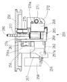
(ロ)キャリッジ部
キャリッジ部700の構成を、図2及び図11、図12に基づいて説明する。図11はキャリッジ部700の要部を概略的に示した図であり、図12は図2におけるキャリッジ部700をE方向から見たときの図である。
【0044】
キャリッジ701は、レンズLEを2つのレンズチャック軸702L、702Rにチャッキングして回転させることができ、また、ベース10に固定されて砥石回転軸601と平行に延びるキャリッジシャフト703に対して回転摺動自在になっている。以下では、キャリッジ701を砥石回転軸601と平行に移動させる方向をX軸、キャリッジ701の回転によりレンズチャック軸(702L、703R)と砥石回転軸601との軸間距離を変化させる方向をY軸として、レンズチャック機構及びレンズ回転機構、キャリッジ701のY軸移動機構、キャリッジ701のX軸移動機構を説明する。
【0045】
<レンズチャック機構及びレンズ回転機構>
キャリッジ701の左腕701Lにチャック軸702Lが、右腕701Rにチャック軸702Rが回転可能に同一軸線上で保持されている。右腕701Rの中央上面にはチャック用モータ710が固定されており、モータ710の回転軸に付いているプーリ711の回転がベルト712を介して、右腕701Rの内部で回転可能に保持されている送りネジ713を回転させる。送りネジ713の回転により送りナット714を軸方向に移動させることにより、送りナット714に連結したチャック軸702Rが軸方向に移動することができ、レンズLEがチャック軸702L、702Rによって挟持される。
【0046】
キャリッジ左腕701Lの左側端部にはチャック軸702Lの軸線を中心にして回動自在なモータ取付用ブロック720が取り付けられており、チャック軸702Lはブロック720を通ってその左端にはギヤ721が固着されている。ブロック720にはレンズ回転用のモータ722が固定されており、モータ722がギヤ724を介してギヤ721を回転することにより、チャック軸702Lへモータ720の回転が伝達される。左腕701Lの内部ではチャック軸702Lにプーリ726が取り付けられており、プーリ726はキャリッジ701の後方で回転可能に保持されている回転軸728の左端に固着されたプーリ730aとタイミングベルト731aにより繋がっている。また、回転軸728の右端に固着されたプーリ730bは、キャリッジ右腕701R内でチャック軸702Rの軸方向に摺動可能に取付けられたプーリ733と、タイミングベルト731bにより繋がっている。この構成によりチャック軸702Lとチャック軸702Rは同期して回転する。
【0047】
<キャリッジのX軸移動機構、Y軸移動機構>
キャリッジシャフト703にはその軸方向に摺動可能な移動アーム740が設けられており、移動アーム740はキャリッジ701と共にX軸方向(シャフト703の軸方向)に移動するように取り付けられている。また、移動アーム740の前方は、シャフト703と平行な位置関係でベース10に固定されたガイドシャフト741上を摺動可能にされている。移動アーム740の後部には、シャフト703と平行に延びるラック743が取り付けられており、このラック743にはベース10に固定されたキャリッジX軸移動用モータ745の回転軸に取り付けられたピニオン746と噛み合っている。これらの構成によりモータ745は移動アーム740と共にキャリッジ701をシャフト703の軸方向に移動させることができる。
【0048】
移動アーム740には揺動ブロック750が、図11(b)のように、砥石の回転中心と一致する軸線Laを中心に回動可能に取り付けられており、また、シャフト703の中心からこの軸線Laまでの距離と、シャフト703の中心からキャリッジ701のチャック軸(702L,702R)の回転中心までの距離とは同じになるように設定されている。揺動ブロック750にはY軸モータ751が取り付けられており、モータ751の回転はプーリ752とベルト753を介して、揺動ブロック750に回転可能に保持された雌ネジ755に伝達される。雌ネジ755内のネジ部には送りネジ756が噛み合わされて挿通されており、雌ネジ755の回転により送りネジ756は上下移動する。
【0049】
送りネジ756の上端には、モータ取付用ブロック720の下端面に当接するガイドブロック760が固定されており、ガイドブロック760は揺動ブロック750に植設された2つのガイド軸758a、758bに沿って移動する。したがって、Y軸モータ751の回転により送りネジ756と共にガイドブロック760を上下させることにより、ガイドブロック760に当接するモータ取付用ブロック720の上下位置を変化させることができる。これにより、ブロック720に取付けられたキャリッジ701もその上下位置を変化させることができる(すなわち、キャリッジ701はシャフト703を回転中心に回旋し、レンズチャック軸(702L、702R)と砥石回転軸601との軸間距離を変化させる)。キャリッジ701の左腕701Lと移動アーム740との間にはバネ762が張り渡されており、キャリッジ701は常時下方に付勢され、レンズLEの加工圧が与えられる。このキャリッジ701の下方への付勢力に対して、キャリッジ701はブロック720がガイドブロック760に当接する位置までしか下降できない。ブロック720には加工終了検知用のセンサ764が取付けられており、センサ764はガイドブロック760に付いているセンサ板765の位置を検知することにより加工終了(研削状態)を検知する。
【0050】
(ハ)レンズ形状測定部
レンズ形状測定部500の構成を、図13〜図16を基に説明する。図13はレンズ形状測定部500を上から見たときの図、図14は図13の左側面図、図15は図13の右側面の要部を示した図である。図16は図13のF−F断面図である。
【0051】
ベース10には支基ブロック501が立設されており、この支基ブロック501には、上下に配置されたガイドレール部502a、502bによってスライドベース510が左右方向(チャック軸と平行な方向)に摺動可能に保持されている。スライドベース510の左端には前方に延びる側板510aが一体的に形成されており、側板510aにはチャック軸702L、702Rと平行な位置関係を持つシャフト511が回転可能に取付けられている。シャフト511の右端部にはレンズ後面測定用の測定子515を持つ測定子アーム514が固着されており、また、シャフト511の中央よりにはレンズ前面測定用の測定子517を持つ測定子アーム516が固着されている。測定子515及び測定子517は共に円筒形状をしており、図13のように先端側は斜めにカットされ、その斜めにカットされた各最先端がレンズLEの後面及び前面に接触する。測定子515の接触点及び測定子517の接触点は対向しており、その間隔は距離不変に配置されている。なお、測定子515の接触点と測定子517の接触点を結ぶ軸線は、図13に示す測定状態のとき、レンズチャック軸(702L,702R)の軸線と平行に所定の位置関係となっている。また、レンズ後面測定用の測定子515はやや長めの円筒部を持ち、レンズ外径の測定(後述する)の際にはその側面をレンズLEのコバ端面に当接させて測定を行う。
【0052】
シャフト511の基部には小ギヤ520が固定されており、側板510aに回転可能取付けられた大ギヤ521が小ギヤ520に噛み合っている。大ギヤ521と側板510aの下方にはバネ523が張り渡されており、バネ523により大ギヤ521が図15上の時計回りに回転する方向に常時引っ張られている。つまり、アーム514、516は小ギヤ520を介して下方に回転するように付勢されている。
【0053】
側板510aには溝503が形成されており、大ギヤ521からはこの溝503を貫通するピン527が偏心して固着されている。ピン527には大ギヤ521を回転させるための第1移動板528が取付けられている。第1移動板528の略中央には長穴528aが形成されており、この長穴528aに側板510aに固着された固定ピン529が係合する。
【0054】
また、支基ブロック501の後方に延びる後部板501aにはアーム回転用のモータ531が取付けられており、モータ531の回転軸に取付けられた回転部材532には回転軸から偏心した位置に偏心ピン533が取付けられている。偏心ピン533には第1移動板528を前後方向(図14上の左右方向)に移動するための第2移動板535が取り付けられている。第2移動板535の略中央には長穴535aが形成されており、この長穴535aに後部板201aに固定された固定ピン537が係合する。第2移動板535の端部にはローラ538が回転可能に取り付けられている。
【0055】
モータ531の回転により偏心ピン533を、図14の状態から時計回りに回転すると、固定ピン537と長穴535aのガイドにより第2移動板535は前側(図14上の右側)に移動する。ローラ538は第1移動板528の端面に当接しているので、第2移動板535の移動によりローラ538は第1移動板528をも前側に移動する。この移動によって第1移動板528がピン527を介して大ギヤ521を回転するようになり、大ギヤ521の回転によりシャフト511に取り付けられた測定子アーム514及び516は起立した状態に退避する。この退避位置へのモータ532の駆動は、回転部材532の回転位置を図示なきマイクロスイッチが検知することにより定められる。
【0056】
モータ531を逆回転すると第2移動板535は引き戻され、大ギヤ521はバネ523に引っ張られて回転し、測定子アーム514及び516は前側に倒される。大ギヤ521の回転は側板510aに形成された溝503の端面にピン527がぶつかることにより制限され、測定子アーム514及び516の測定位置が決定される。この測定位置まで測定子アーム514及び516が回転したことは、図16に示すように、側板510aに取り付けられたセンサ524で、大ギヤ521に付いているセンサ板525の位置を検知することにより検出する。
【0057】
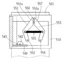
スライドベース510(測定子アーム514,515)の左右移動機構を図16及び図17により説明する。図17は左右移動の状態を説明する図である。
【0058】
スライドベース510の内部は開口が形成されており、その開口の下端部にはラック540が設けられている。ラック540には支基ブロック501側に固定されたエンコーダ542のピニオン543と噛み合っており、エンコーダ542はスライドベース510の左右の移動方向と移動量を検知する。スライドベース510の開口から覗く支基ブロック501の壁面には、「く」の字状の駆動板551が軸552を中心に回転可能に、逆「く」の字状の駆動板553が軸554を中心に回転可能にそれぞれ取り付けられており、駆動板551と駆動板553の間には両者を接近させる方向に付勢力を持つバネ555が張り渡されている。また、支基ブロック501の壁面には制限ピン557が植設されており、スライドベース510に外力が働いていないときは、この制限ピン557に駆動板551の上部端面551aと駆動板553の上部端面553aが共に当接した状態となり、これが左右移動の原点となる。
【0059】
一方、スライドベース510の上部には、駆動板551の上部端面551aと駆動板553の上部端面553aとの間の位置にガイドピン560が固着されている。スライドベース510に右方向に移動する力が働くと、図17(a)のように、ガイドピン560は駆動板553の上部端面553aに当接して駆動板553は右方向に傾く。このとき、駆動板551側は制限ピン557によって固定されているので、スライドベース510はバネ555により左右移動の原点まで戻される方向(左方向)に付勢される。逆に、スライドベース510に左方向に移動する力が働くと、図17(b)のように、ガイドピン560は駆動板551の上部端面551aに当接して駆動板551は左方向に傾くが、駆動板553側は制限ピン557によって固定される。したがって、今度はスライドベース510がバネ555により左右移動の原点まで戻される方向(右方向)に付勢される。このようなスライドベース510の移動から、レンズ後面に接触する測定子515、レンズ前面に接触する測定子517の移動量(チャック軸の軸方向の移動量)が1つのエンコーダ542により検知される。
【0060】
なお、図13において、50は加工室の防水カバーを示し、防水カバー50からはシャフト511、測定子アーム514、516、及び測定子515、517のみが露出する状態となっている。51は防水カバー50とシャフト511とのシール材である。加工時には図示なきノズルから研削水が噴射されるが、レンズ形状測定部500を加工室の後方に配置するとともに、上記のような構成により、防水カバー501から露出するシャフト511のシールドを行うだけでレンズ形状測定部500の電装部や移動機構の防水を行うことができ、防水機構が簡略されている。
【0061】
次に、以上のようの構成を持つ装置において、その動作を図18の制御系ブロック図を使用して説明する。
【0062】
装置による加工に先立ち、眼鏡枠測定装置2による玉型形状の測定を行う。まず、眼鏡フレームFを測定する場合を説明する。眼鏡枠測定装置2のフレーム保持部200は眼鏡フレームFの両枠保持及び片眼保持が可能であるが、ここでは両枠保持について説明する。
【0063】
前スライダー202を手前に引いて前スライダー202と後スライダー203の間隔を広げる。眼鏡フレームFの上部をクランプピン231Ra,231Rb及びクランプピン231La,231Lbの間に位置させ、眼鏡フレームFの下部をクランプピン230Ra,230Rb及びクランプピン230La,230Lbの間に位置させる。前スライダー202及び後スライダー203によりはバネ213により常に基準線L1に向かう求心的な力が働いているので、これにより両スライダーの間隔が狭められ、眼鏡フレームFが基準線L1を中心にして保持される。このとき、フレーム保持部200の保持面は装置本体1の上面に沿って前側に傾斜して配置されているので、眼鏡フレームFのセットが行い易い。
【0064】
眼鏡フレームFのセットができたら、スイッチパネル部410の両眼トレース用スイッチ412を押すと、眼鏡枠測定装置2側の制御部150はモータ223を駆動させ、シャフト220の回転により4個所のクランプピンを閉じてフレームFを固定する。フレームFの固定が完了したら、計測部240を作動させてフレーム形状の測定を行う。両眼トレースの場合、制御部150はモータ244を駆動して、測定子280がフレームFの右枠側の所定位置に位置するように横移動ベース241を移動しておく。また、モータ254の駆動により回転ベース250を回転させ、測定子280の先端がクランプピン230Ra,230Rb側を向く位置に初期設定しておく。その後、モータ270の駆動により上下支基265を上昇させて測定子280を測定基準平面の高さに位置させる(本実施形態では、測定基準平面も前側に傾斜している)。最下点位置から測定子280を上昇させた際の移動量はエンコーダ272の検出から得られ、制御部150はエンコーダ272の検出情報を基に測定子280を測定基準平面の高さに位置させる。
【0065】
その後、制御部150はモータ257を駆動して移動支基260を移動し、測定子280の先端をフレームFの枠溝に挿入する。この移動に際してはDCモータ257を使用しているので、モータ257への駆動電流(駆動トルク)の制御により所定の駆動トルクを掛けることで、フレームを変形させずに、かつ測定子280が外れない程度の弱い押圧力を与えることができる。続いて、パルスモータ254を予め定めた単位回転パルス数毎に回転させ、回転ベース250と共に測定ユニット255を回転する。この回転により、測定子280と共に移動支基260がレンズ枠溝の動径に従って、ガイドレール受け267のレール方向に移動し、その移動量はエンコーダ258によって検出される。また、測定子280と共に上下支基265はレンズ枠溝の反り(カーブ)に沿って上下し、その移動量がエンコーダ272によって検出される。パルスモータ254の回転角θと、エンコーダ258による検出量rと、エンコーダ272による検出量zとから、レンズ枠形状が(rn,θn,zn)(n=1,2,……N)として計測される。
【0066】
測定ユニット255を回転させながらの測定中、制御部150は測定基準平面の傾斜と検出された動径の変化情報に基づきモータ257の駆動を制御する。すなわち、測定基準平面が傾斜しているので、レンズ枠溝に対する測定子280の押圧力を一定にするためには、測定ユニット255の回転角毎にその荷重分をキャンセルするように、モータ257の駆動を変化させる。回転角毎の駆動電流の変化量は、例えば、測定子280の位置が変化しないモータ257への駆動電流のデータを単位回転角度毎に予め求めておく。また、測定ユニット255が水平方向に移動するとき(測定ユニット255の荷重がキャンセルされている角度)を基準にして、レンズ枠溝に対して測定子280により所定の押圧力を掛けるための基準の駆動電流を求めておく。そして、この両者の関係から傾斜分を考慮した回転角毎の駆動電流の変化データを定めることができる。例えば、基準の駆動電流に対して、角度毎の駆動電流データの比率で変化させる。
【0067】
さらに、測定中に測定子280が外れないように、また、眼鏡枠の変形を抑えるように、制御部150はレンズ枠溝の動径の変化に応じてモータ257への駆動電流を変化させる。まず、制御部150は計測済みの動径データ(rn,θn)(n=1,2,……)から未計測部分の動径の変化を予測する。例えば、所定の動径角度α(例;3〜5度)毎の計測済みの動径データから、現在の測定点における動径変化の傾きを求める。これは、動径角度α間のデータを微分処理したり、平均処理したりして求めることができる。未計測部分の次の動径角度αにおける測定点もこの求めた動径変化の傾きの延長上にあるものと仮定し、未計測部分の動径変化を予測する。そして、未計測部分の動径長が長くなる方向に変化していくと予測されたときは、直前の動径角度αのときの駆動トルクに対してモータ257の駆動トルクを強める。その駆動トルク(駆動電流)の変化量は、動径変化の傾きの程度に応じて定めても良いし、動径変化の傾きがある範囲を超える毎に駆動トルクを所定量強めるようにしても良い。これにより、測定子280は動径長が長くなる方向への移動速度が速められ、測定中における枠溝からの測定子280の外れを防止できる。
【0068】
一方、未計測部分の動径長が短くなる方向に変化していくと予測されたときは、直前の動径角度αのときの駆動トルクに対してモータ257の駆動トルクを弱めていく。このときの駆動トルクの変化量も、動径変化の傾きの程度に応じて定めても良いし、動径変化の傾きがある範囲を超える毎に駆動トルクを所定量弱めるようにしても良い。これにより、レンズ枠溝にかかる測定子180の押圧力の増加を抑え、眼鏡枠の変形を防止できる。なお、通常、眼鏡枠の動径は徐々に変化するので、モータ257の駆動トルクも徐々に弱めていき、最終的に駆動トルク0になれば動径長が短くなる方向の変化に対しても、過剰な押圧力を避けることができる。また、急激に動径長が短くなる方向へ変化していくと予測されたときは、モータ257を逆回転することにより、眼鏡枠への押圧力の負荷を少なくしても良い。
【0069】
また、測定途中のモータ257の駆動制御は、次のようにすることもできる。例えば、制御部150による未計測部分の動径変化の予測は、計測済みの測定データから測定点の動径変化の傾きを法線方向として得た後、次の測定点はこの法線方向の延長線上にあるものとして予測する。計測済みの測定データは全てを対象にしなくとも、直前のある角度分のデータであっても良い。
【0070】
また、順次得られる動径データから動径長さが増加又は減少に転じる変曲点が得られるので(ある範囲のデータを見るとなお良い)、動径長さが増加に転じることが検出されたらモータ257の駆動トルクを強め、逆に動径長さが減少に転じることが検出されたらモータ257の駆動トルクを弱めるように制御するようにしても良い。動径長さが減少に転じるときには眼鏡枠には測定子280からの押圧力が強く働くので、このように駆動トルクを弱めることにより、眼鏡枠の変形を抑えるとともに、フレーム保持部200に保持された眼鏡枠のずれも抑えることができる。
【0071】
また、眼鏡枠の構造上、変形が最も生じ易いのは、眼鏡枠の下側(装用した状態の下側を言)から左右両枠を繋ぐブリッジにかけての範囲であり、この範囲は測定子280が外れ難いところでもある(通常、動径が緩やかに変化していく)。したがって、この範囲(予め定めておいても良いし、測定途中のデータから予測しても良い)の角度分だけ他の測定部分よりモータの駆動トルクを十分に弱いものとする制御をすることもできる。このように測定途中のモータ257の駆動制御は種々の方法によって行うことができる。
【0072】
制御部150はモータ257の駆動制御に加えて、検出されたレンズ枠の反り(上下)の変化情報に基づき測定子280を上下するモータ270の駆動を制御する。動径情報の変化に応じた制御の方法と同様に、制御部150は計測済みの上下データ(θn,zn)(n=1,2,……)から、現在の測定点における上下変化の傾きを求め、次ぎの測定点も上下変化の傾き延長にあるものと仮定して未計測部分の変化を予測する。その変化に応じてモータ270への駆動電流の変化させる。レンズ枠溝が上方向に変化していくと予測されるときは、その変化度合いに追従するように測定子280を上昇させる。レンズ枠溝が下方向に変化していくと予測されるときは、その変化度合い追従するように測定子280を下降させる。これは上下変化がある値を超える予測されたときに所定量分だけ移動するようにしても良い。
【0073】
このようなモータ257、270の駆動制御により、測定中における測定子280の外れを防止できると共に、眼鏡枠の変形も抑えることができる。フレームFの右枠側の測定ができると、同様に左枠側の測定が行われる。
【0074】
型板又はダミーレンズを測定する場合を説明する。型板又はダミーレンズは、前述した要領により型板ホルダー310の型板保持部320又はカップ保持部330に取り付ける。ダミーレンズの場合も、特別な固定用部品を用意することなく、ボタン314の操作により簡単に型板ホルダー310に取付けできる。
【0075】
型板ホルダー310への取付けができたら、前スライダー202を手前まで引いて、取付け板300の上面に型板ホルダー310を固定する。型板ホルダー310の鍔344(348)が前スライダー202の窪み面202aに係合するので、前スライダー202及び後スライダー203の開放が固定される。前スライダー202の開放状態はセンサ235により検出され、型板測定用モードであることが検知される。
【0076】
型板ホルダー310のセット後、測定する型板(又はダミーレンズ)が右用の場合はスイッチパネル部410の右トレーススイッチ413を、型板(又はダミーレンズ)が左用の場合は左トレーススイッチ411を押す。なお、型板ホルダー310を使用した測定の際には、測定軸290の頂部を押して測定軸を上昇させておく。
【0077】
制御部150はモータ244を駆動して計測部240を中央の測定位置に位置させる。その後、測定軸290が中心側に向かうようにモータ257を駆動して移動支基260を移動する。測定軸290が型板(又はダミーレンズ)の端面に当接した状態で、パルスモータ254を予め定めた単位回転パルス数毎に回転させ、測定ユニット255を回転する。型板の動径に従って測定軸290が移動し、その移動量はエンコーダ258によって検出され、玉型形状が計測される。
【0078】
フレームF等の玉型形状の測定ができたら、操作者はスイッチパネル部420のデータスイッチ421を押すことにより、玉型形状データがデータメモリ161に転送され、ディスプレイ415には玉型形状が図形表示される。操作者はスイッチパネル部420に配置されるデータ入力用のスイッチを操作して、装用者のPD値や光学中心の高さ位置データ等のレイアウトデータを入力する。また、フレームの材質、レンズ材質等の加工条件のデータを入力する。
【0079】
データの入力が完了したら、操作者は被加工レンズLEに固定された固定治具用のカップの基部をレンズチャック軸702Lが持つカップホルダに装着した後、スイッチパネル部420のチャックスイッチ422を押すことによりモータ710を駆動し、レンズチャック軸702Rが移動することによりチャッキングする。このチャッキングに際してレンズLEがレンズチャック軸702Lから外れないように保持する必要がある場合でも、チャックスイッチ422は加工窓402の手前側左右中央付近(レンズLEのチャッキング位置付近)に配置されているので、操作者はレンズLEを保持し易い方の手で保持しながら、もう片方の手でチャックスイッチ422を容易に操作することができる。
【0080】
レンズチャック後、スタートスイッチ423を押して装置を作動させる。主制御部160は、加工シーケンスプログラムに基づき、まずレンズ形状測定部500を用いてレンズ形状の測定を実行する。主制御部160はモータ531を駆動してシャフト511を回転させ、測定子アーム514,516を退避位置から測定位置に位置させる。主制御部160は入力された玉型形状の動径データ及びレイアウトデータから算出した加工形状に基づき、測定子515と測定子517を結ぶ軸線Lbに対するレンズチャック軸の軸線との距離を変化させるようにキャリッジ701を上下移動し、チャッキングしたレンズLEを図13のように測定子515と測定子517の間に位置させる。その後、モータ745の駆動によりキャリッジ701を測定子517側へ所定量分だけ移動し、レンズLEの前面屈折面の測定子517を当接させる。測定子517側へのレンズLEの初期測定位置は、スライドベース510の左側移動範囲のほぼ中間であり、測定子517にはバネ555により常にレンズLEの前側屈折面に当接するように力が働く。
【0081】
測定子517が前側屈折面に当接した状態で、モータ722によりレンズLEを回転するとともに、加工形状データを基にモータ751を駆動してキャリッジ701を上下させる(レンズチャック軸702L,702Rの軸線と軸線Lbの距離を変化させる)。こうしたレンズLEの回転及び移動に伴い、測定子517はレンズ前面形状に沿って左右方向に移動する。この移動量はエンコーダ542により検出されレンズLEの前面屈折面形状が計測される。
【0082】
レンズ前面側の測定が終了したら、主制御部160はそのままキャリッジ701を右方向へ移動し、レンズLEの後側屈折面に測定子515を当接させて測定面を切換える。後面測定の初期測定位置もスライドベース510の右側移動範囲のほぼ中間であり、測定子515には常にレンズLEの後側屈折面に当接するように力が働く。その後、レンズLEを1回転させながら前側屈折面の測定と同様にして測定子515の移動量から後側屈折面形状を計測する。レンズの前側屈折面形状及び後側屈折面形状が得られると、両者からコバ厚情報を得ることができる。レンズ形状の測定終了後は、主制御部160はモータ531を駆動させて測定子アーム514,516を退避させる。
【0083】
本装置のレンズ形状測定部500はレンズ外径の測定機能を備えており、この測定を行うときは次のようにする。主制御部160はモータ745の駆動し、図14の2点鎖線で示すように、レンズLEのコバ面が測定子517の側面部分まで達するようにキャリッジ701を移動する。その後、玉型の加工径形状データを基にレンズLEを回転させながらモータ751を駆動してキャリッジ701を上下させ、レンズチャック軸702L,702Rの軸線と軸線Lbの距離を変化させる。こうしたキャリッジ701の上下移動により、レンズ外径が玉型形状を満たしている場合、測定子515の側面はレンズLEのコバ面に当接し、測定子アーム514は持ち上げられるようになり、センサ524がこれを検知する。玉型形状に対してレンズ外径が不足している場合、測定子515の側面はレンズLEのコバ面に当接しないので、測定子アーム514は最下点に位置したままとなり、センサ524がセンサ板525を検知してレンズ径不足が検出される。こうしてレンズLEを1回転させることにより、レンズLEの全周についてのレンズ径不足が検出できる。
【0084】
玉型形状に対してレンズ外径の不足情報が得られたときは、ディスプレイ415上に表示されている玉型図形表示に対してその不足部分を点滅させることにより、操作者に不足部分を知らせることができる。
【0085】
なお、こうした全周についてのレンズ外径測定は加工シーケンスプログラムの一つとして行っても良いが、スイッチ425を押すことによりレンズ外径の測定のみを単独で行うようにしても良い。
【0086】
レンズ形状の測定が完了すると、加工条件の入力データに従ってレンズLEの加工が実行される。例えば、レンズLEがプラスチックの場合、主制御部160は粗砥石602b上にレンズLEがくるようにキャリッジ701を745により移動させた後、玉型の動径データに基づいてキャリッジ701を上下移動させて加工する。ヤゲン加工を行う場合、主制御部160はレンズ形状データから求められるヤゲン加工用データに基づいてキャリッジ701を移動制御し、仕上げ砥石602cによるヤゲン仕上げ加工を行う。ヤゲン加工用データはレンズ形状データ及び玉型形状データに基づいて主制御部160により算出される。
【0087】
【発明の効果】
以上説明したように、本発明によれば、眼鏡枠の変形を抑え、測定子が眼鏡枠溝から外れることなく測定を行うことができる。また、眼鏡枠測定装置を傾斜して設置できるので、装置の配置に自由度が増し、眼鏡枠の装置へのセットが行い易くなる。
【図面の簡単な説明】
【図1】本発明に係る眼鏡レンズ加工装置の外観構成を示す図である。
【図2】装置本体の筐体内に配置される加工部の構成を示す斜視図である。
【図3】眼鏡枠測定装置におけるフレーム保持部200の平面図である。
【図4】図3のA−A断面の要部を示す図である。
【図5】眼鏡枠測定装置における計測部の平面図である。
【図6】測定子ユニットを説明するための側面図である。
【図7】図6のC方向の図である。
【図8】型板ホルダーにおける、型板を取り付けるための型板保持部を上に向けたときの斜視図である。
【図9】型板ホルダーにおける、ダミーレンズを取り付けるためのカップ保持部側を上に向けたときの斜視図である。
【図10】型板ホルダーの長手方向の断面図である。
【図11】キャリッジ部の要部を概略的に示した図である。
【図12】図2におけるキャリッジ部をE方向から見たときの図である。
【図13】レンズ形状測定部を上から見たときの図である。
【図14】図13の左側面図である。
【図15】図13の右側面の要部を示した図である。
【図16】図13のF−F断面図である。
【図17】レンズ形状測定部の左右移動の状態を説明する図である。
【図18】本装置の制御系ブロックである。
【符号の説明】
1 装置本体
2 眼鏡枠測定装置
150 制御部
200 フレーム保持部
280 測定子
257 DCモータ
258 エンコーダ
270 DCモータ
272 エンコーダ[0001]
BACKGROUND OF THE INVENTION
The present invention relates to a spectacle frame shape measuring device for measuring the shape of a lens such as a spectacle frame or a template, and a spectacle lens processing device having the spectacle frame shape measuring device.
[0002]
[Prior art]
As a spectacle frame shape measuring apparatus, as described in JP-A-4-18516, the measuring element is brought into contact with the frame groove of the spectacle frame held by the frame holding part while pressing the measuring element to the frame. It is known that the lens shape of a spectacle frame is measured from the movement information by moving along a groove. In this type of conventional apparatus, when the measuring element is brought into contact with the frame groove, the measurement is performed by pressing the measuring element toward the frame groove side (the radial direction side of the target lens shape) by the biasing force of the spring.
[0003]
[Problems to be solved by the invention]
However, the conventional spectacle frame shape measuring apparatus has the following problems.
[0004]
(1) In the method of pressing a probe using a spring, the spring expands and contracts according to the moving radius of the spectacle frame, so the pressing force against the spectacle frame during measurement is not constant. A certain amount of force even when the spring is contracted (a part with a long radial length) in order to be able to handle spectacle frames of various shapes and to prevent the probe from being removed from the frame groove during measurement. Need to be added. When measurement is performed with the spring force determined in this way, a large pressing force is applied to the frame in a portion with a short moving radius, and deformation occurs in the case of a spectacle frame that is soft in terms of material or structure. There is a fear. In order to perform measurement without deforming the spectacle frame, it is preferable to apply a pressing force as weak as possible so that the probe does not come off and a constant pressing force as much as possible on the frame groove.
[0005]
(2) Also, in the method of pressing the probe using a spring, it is necessary to hold the spectacle frame by the frame holding unit and keep the moving unit of the measuring unit almost horizontal without tilting, and it is free to arrange the device. There was no degree. In other words, if the moving mechanism of the measuring element is inclined, the pressing force of the measuring element varies depending on the angular direction of the moving radius to be measured due to the influence of its own weight, and the measuring element may be deformed or come off the frame groove. growing.
[0006]
(3) After inserting the probe into the frame groove of the spectacle frame, the probe is generally free to move up and down along the frame groove. It was easy to come off.
[0007]
In view of the above-described problems of the prior art, the present invention reduces the risk of deformation of the spectacle frame, and spectacle frame measuring apparatus capable of performing measurement without the stylus being detached from the spectacle frame groove and spectacle lens processing apparatus having the spectacle frame measuring apparatus The technical challenge is to provide
[0008]
It is another object of the present invention to provide a spectacle frame measuring apparatus having a high degree of freedom in arrangement of the apparatus and a spectacle lens processing apparatus having the spectacle frame measuring apparatus.
[0009]
[Means for Solving the Problems]
In order to solve the above problems, the present invention is characterized by having the following configuration.
[0010]
(1) The eyeglass frame is held in the desired state by the holding means, and the three-way movement of the measuring element is detected by the detecting means by moving the measuring element along the frame groove while contacting the measuring element with the frame groove of the spectacle frame. By doing In the spectacle frame shape measuring apparatus for measuring the lens shape of the spectacle frame, Said Measuring element Glasses frame For moving in the radial direction Based on the change in the radial information measured by the drive motor and the detection means, the radial fluctuation of the unmeasured portion is predicted, and the drive of the drive motor is controlled according to the predicted radial fluctuation. And a control means.
(2) (1) In the eyeglass frame shape measuring apparatus, a second drive motor for moving the measuring element in a second direction orthogonal to the radial direction, and a measuring means for obtaining movement information of the measuring element in the second direction; And a second control means for controlling the driving of the second drive motor in the middle of measurement based on the result obtained by the measurement means, and the second control means has been measured by the measurement means. Predicting a variation in the second direction of the unmeasured portion based on the variation information in the second direction, and drivingly controlling the second drive motor so as to move the probe in accordance with the predicted variation. Features.
(3) The eyeglass frame is held on the measurement reference plane by a clamp pin, and the three-way movement of the measuring element is detected by the detecting means by moving the measuring element along the frame groove while bringing the measuring element into contact with the frame groove of the spectacle frame. Thus, in the spectacle frame shape measuring apparatus for measuring the lens shape of the spectacle frame, the spectacle frame holding means for clamping the spectacle frame by inclining the measurement reference plane by a predetermined angle with respect to the installation horizontal plane, and the measuring element A drive motor for moving in the radial direction of the spectacle frame parallel to the measurement reference plane; and a control means for controlling the drive of the drive motor so as to cancel the load due to the inclination of the measurement reference plane. To provide Features.
[0017]
DETAILED DESCRIPTION OF THE INVENTION
Hereinafter, embodiments of the present invention will be described with reference to the drawings.
[0018]
(1) Overall configuration
FIG. 1 is a diagram showing an external configuration of an eyeglass lens processing apparatus according to the present invention. A spectacle
[0019]
FIG. 2 is a perspective view illustrating a configuration of a processing unit disposed in the housing of the apparatus main body 1. A
[0020]
A lens
[0021]
(2) Configuration of each part
(I) Eyeglass frame measuring device
The main structure of the spectacle
[0022]
<Frame holder>
The configuration of the
[0023]
On the holding
[0024]
The eyeglass frame F is clamped by clamp pins arranged at a total of four locations: clamp pins arranged at two left and right positions of the
[0025]
These clamp pins are opened and closed by driving a clamping
[0026]
In addition, an
[0027]
At the time of measurement using the
[0028]
<Measurement unit>
The structure of the
[0029]
On the
[0030]
The configuration of the
[0031]
A
[0032]
A
[0033]
Further, a
[0034]
A limiting
[0035]
In FIG. 6, a measuring
[0036]
<Template holder>
The configuration of the
[0037]
In the main body block 311 of the
[0038]
A
[0039]
When fixing the
[0040]
When fixing the
[0041]
A mounting
[0042]
When attaching such a
[0043]
(B) Carriage section
A configuration of the
[0044]
The
[0045]
<Lens chuck mechanism and lens rotation mechanism>
A
[0046]
A
[0047]
<Carriage X-axis movement mechanism, Y-axis movement mechanism>
The
[0048]
As shown in FIG. 11B, a
[0049]
A
[0050]
(C) Lens shape measurement unit
The configuration of the lens
[0051]
A
[0052]
A
[0053]
A
[0054]
Further, a
[0055]
When the
[0056]
When the
[0057]
A lateral movement mechanism of the slide base 510 (
[0058]
An opening is formed in the
[0059]
On the other hand, a
[0060]
In FIG. 13,
[0061]
Next, the operation of the apparatus having the above configuration will be described using the control system block diagram of FIG.
[0062]
Prior to processing by the apparatus, the lens shape is measured by the spectacle
[0063]
Pulling the
[0064]
When the spectacle frame F is set, when the
[0065]
Thereafter, the
[0066]
During the measurement while rotating the
[0067]
Further, the
[0068]
On the other hand, when it is predicted that the radial length of the non-measured portion will be shortened, the driving torque of the
[0069]
Further, the drive control of the
[0070]
In addition, since the inflection point at which the radial length starts to increase or decrease is obtained from the radial data obtained sequentially (it is better when looking at a certain range of data), it is detected that the radial length starts to increase. Then, the driving torque of the
[0071]
Further, in the structure of the spectacle frame, the deformation is most likely to occur in the range from the lower side of the spectacle frame (the lower side of the wearing state) to the bridge connecting the left and right frames, and this range is the measuring
[0072]
In addition to the drive control of the
[0073]
Such drive control of the
[0074]
A case where a template or a dummy lens is measured will be described. The template or dummy lens is attached to the
[0075]
When the attachment to the
[0076]
After setting the
[0077]
The
[0078]
When the target lens shape such as the frame F can be measured, the operator presses the data switch 421 of the
[0079]
When the data input is completed, the operator attaches the base of the fixing jig cup fixed to the lens LE to be processed to the cup holder of the
[0080]
After the lens chuck, the
[0081]
While the
[0082]
When the measurement on the front side of the lens is completed, the
[0083]
The lens
[0084]
When insufficient information of the lens outer diameter is obtained for the target lens shape, the insufficient part is blinked with respect to the target lens graphic display displayed on the
[0085]
The lens outer diameter measurement for the entire circumference may be performed as one of the processing sequence programs, but only the lens outer diameter may be measured by pressing the
[0086]
When the measurement of the lens shape is completed, the processing of the lens LE is executed according to the input data of the processing conditions. For example, when the lens LE is plastic, the
[0087]
【The invention's effect】
As described above, according to the present invention, it is possible to suppress the deformation of the spectacle frame and perform measurement without the stylus being detached from the spectacle frame groove. In addition, since the spectacle frame measuring device can be installed at an inclination, the degree of freedom in arrangement of the device increases, and the spectacle frame can be easily set on the device.
[Brief description of the drawings]
FIG. 1 is a diagram showing an external configuration of an eyeglass lens processing apparatus according to the present invention.
FIG. 2 is a perspective view illustrating a configuration of a processing unit disposed in a housing of the apparatus main body.
FIG. 3 is a plan view of a
4 is a view showing a main part of the AA cross section of FIG. 3; FIG.
FIG. 5 is a plan view of a measuring unit in the spectacle frame measuring apparatus.
FIG. 6 is a side view for explaining a probe unit.
7 is a view in the direction C of FIG.
FIG. 8 is a perspective view of the template holder when a template holding portion for attaching the template is directed upward.
FIG. 9 is a perspective view of the template holder when a cup holding part side for attaching a dummy lens is directed upward.
FIG. 10 is a longitudinal sectional view of a template holder.
FIG. 11 is a diagram schematically illustrating a main part of a carriage unit.
12 is a view when the carriage portion in FIG. 2 is viewed from the E direction. FIG.
FIG. 13 is a diagram of the lens shape measurement unit as viewed from above.
14 is a left side view of FIG.
15 is a view showing a main part of the right side surface of FIG. 13;
16 is a cross-sectional view taken along line FF in FIG.
FIG. 17 is a diagram illustrating a state in which the lens shape measurement unit is moved left and right.
FIG. 18 is a control system block of the apparatus.
[Explanation of symbols]
1 Main unit
2 Eyeglass frame measuring device
150 Control unit
200 Frame holder
280 probe
257 DC motor
258 Encoder
270 DC motor
272 Encoder
Claims (3)
Priority Applications (9)
| Application Number | Priority Date | Filing Date | Title |
|---|---|---|---|
| JP12539599A JP3695988B2 (en) | 1999-04-30 | 1999-04-30 | Eyeglass frame shape measuring device |
| DE60042467T DE60042467D1 (en) | 1999-04-30 | 2000-04-27 | Stencil holder, targeted Linzenform measuring device with this holder, and eyeglass lens processing device with this measuring device |
| DE60033884T DE60033884T3 (en) | 1999-04-30 | 2000-04-27 | Spectacle frame measuring device and spectacle lens processing device with the same |
| ES00108983T ES2327891T3 (en) | 1999-04-30 | 2000-04-27 | TEMPLATE SUPPORT, A WISHED LENS MEASURING DEVICE THAT INCLUDES THIS SUPPORT, AND A GLASS LENS PROCESSING DEVICE THAT HAS THIS DEVICE. |
| EP00108983A EP1050371B1 (en) | 1999-04-30 | 2000-04-27 | Template holder, target lens shape measuring device having the holder, and eyeglass lens processing apparatus having the device |
| ES00108985T ES2282068T5 (en) | 1999-04-30 | 2000-04-27 | A GAUGE MOUNTING METHOD DEVICE AND A GLASS LENS PROCESSING DEVICE CONTAINING IT. |
| EP00108985A EP1050373B2 (en) | 1999-04-30 | 2000-04-27 | Eyeglass-frame-shape measuring device and eyeglass-lens processing apparatus having the same |
| US09/561,970 US6350190B1 (en) | 1999-04-30 | 2000-05-01 | Template holder, target lens shape measuring device having the holder, and eyeglass lens processing apparatus having the device |
| US09/561,957 US6325700B1 (en) | 1999-04-30 | 2000-05-01 | Eyeglass-frame-shape measuring device and eyeglass-lens processing apparatus having the same |
Applications Claiming Priority (1)
| Application Number | Priority Date | Filing Date | Title |
|---|---|---|---|
| JP12539599A JP3695988B2 (en) | 1999-04-30 | 1999-04-30 | Eyeglass frame shape measuring device |
Publications (3)
| Publication Number | Publication Date |
|---|---|
| JP2000314617A JP2000314617A (en) | 2000-11-14 |
| JP2000314617A5 JP2000314617A5 (en) | 2004-10-14 |
| JP3695988B2 true JP3695988B2 (en) | 2005-09-14 |
Family
ID=14909088
Family Applications (1)
| Application Number | Title | Priority Date | Filing Date |
|---|---|---|---|
| JP12539599A Expired - Fee Related JP3695988B2 (en) | 1999-04-30 | 1999-04-30 | Eyeglass frame shape measuring device |
Country Status (5)
| Country | Link |
|---|---|
| US (1) | US6325700B1 (en) |
| EP (1) | EP1050373B2 (en) |
| JP (1) | JP3695988B2 (en) |
| DE (1) | DE60033884T3 (en) |
| ES (1) | ES2282068T5 (en) |
Cited By (1)
| Publication number | Priority date | Publication date | Assignee | Title |
|---|---|---|---|---|
| EP2105253A1 (en) | 2008-03-28 | 2009-09-30 | Kabushiki Kaisha TOPCON | Eyeglass frame shape-measuring apparatus |
Families Citing this family (52)
| Publication number | Priority date | Publication date | Assignee | Title |
|---|---|---|---|---|
| JP4360764B2 (en) * | 2000-04-28 | 2009-11-11 | 株式会社トプコン | Lens peripheral processing method, lens peripheral processing apparatus, and spectacle lens for spectacle lens |
| JP4566372B2 (en) * | 2000-07-19 | 2010-10-20 | 株式会社トプコン | Lens frame shape measuring device |
| JP4267228B2 (en) * | 2001-12-03 | 2009-05-27 | 株式会社トプコン | Lens frame shape measuring device |
| JP2004003944A (en) | 2002-04-08 | 2004-01-08 | Hoya Corp | Instrument for measuring shape of spectacl eframe |
| US7090559B2 (en) * | 2003-11-19 | 2006-08-15 | Ait Industries Co. | Ophthalmic lens manufacturing system |
| JP4707965B2 (en) * | 2004-04-30 | 2011-06-22 | 株式会社ニデック | Spectacle lens peripheral processing method, spectacle lens peripheral processing system, and spectacle frame shape measuring apparatus |
| FR2870934B1 (en) * | 2004-05-28 | 2006-09-08 | Essilor Int | CONTOUR READING APPARATUS COMPRISING A ROTATING MOBILE PROBE |
| FR2870933B1 (en) * | 2004-05-28 | 2008-03-14 | Essilor Int | CONTOUR READING APPARATUS HAVING AN EFFORT SENSOR |
| JP4774203B2 (en) * | 2004-10-01 | 2011-09-14 | 株式会社ニデック | Eyeglass lens processing equipment |
| JP4708035B2 (en) * | 2005-01-06 | 2011-06-22 | 株式会社ニデック | Eyeglass lens processing equipment |
| JP4388912B2 (en) * | 2005-05-31 | 2009-12-24 | 株式会社ニデック | Eyeglass lens processing equipment |
| KR100645779B1 (en) | 2005-06-13 | 2006-11-14 | 주식회사 휴비츠 | Apparatus for processing eyeglass lens having member for measuring lens curvature |
| FR2890189B1 (en) | 2005-08-31 | 2008-02-01 | Essilor Int | PROBE PILOTAGE METHOD FOR READING EYEGLASS MOUNT DRESSER |
| US8295961B2 (en) * | 2005-12-26 | 2012-10-23 | Hoya Corporation | Spectacle lens supply system, ordering system, and manufacturing method |
| JP4841257B2 (en) * | 2006-02-03 | 2011-12-21 | 株式会社ニデック | Eyeglass lens peripheral processing equipment |
| JP2007203423A (en) * | 2006-02-03 | 2007-08-16 | Nidek Co Ltd | Spectacle lens peripheral fringe working device |
| JP4749892B2 (en) * | 2006-02-28 | 2011-08-17 | 株式会社ニデック | Hole data input device and spectacle lens processing device including the same |
| JP4841269B2 (en) | 2006-02-28 | 2011-12-21 | 株式会社ニデック | Eyeglass lens processing equipment |
| JP2007240280A (en) * | 2006-03-07 | 2007-09-20 | Nidek Co Ltd | Apparatus for measuring eyeglass frame shape |
| FR2898690B1 (en) | 2006-03-17 | 2008-05-23 | Essilor Int | PROBE DRIVING METHOD FOR READING A GOGGLE MOUNT DRAWER AND CORRESPONDING READING APPARATUS |
| JP5122844B2 (en) * | 2007-03-20 | 2013-01-16 | 株式会社トプコン | Lens frame shape measuring device |
| DE102007015808A1 (en) | 2007-03-30 | 2008-10-02 | Buchmann Deutschland Gmbh | Method for scanning the contour of spectacle-receiving openings and use of the device for scanning the contour of spectacle-detecting openings for the peripheral grinding of spectacle lenses |
| JP5265127B2 (en) * | 2007-03-30 | 2013-08-14 | 株式会社ニデック | Eyeglass lens processing equipment |
| JP4920514B2 (en) | 2007-07-04 | 2012-04-18 | 株式会社ニデック | Ball shape measuring device |
| JP5259144B2 (en) | 2007-09-11 | 2013-08-07 | 株式会社ニデック | Lens frame shape measuring device |
| JP5259145B2 (en) | 2007-09-11 | 2013-08-07 | 株式会社ニデック | Lens frame shape measuring device |
| JP5483227B2 (en) * | 2008-03-28 | 2014-05-07 | Hoya株式会社 | Eyeglass lens manufacturing equipment |
| JP2009300427A (en) * | 2008-05-14 | 2009-12-24 | Topcon Corp | Apparatus and method for measuring shape of eyeglass element |
| JP5372659B2 (en) * | 2009-08-24 | 2013-12-18 | リコーエレメックス株式会社 | Eyeglass shape measuring device |
| JP5562624B2 (en) | 2009-12-09 | 2014-07-30 | 株式会社ニデック | Eyeglass frame shape measuring device |
| JP5586930B2 (en) | 2009-12-09 | 2014-09-10 | 株式会社ニデック | Eyeglass frame shape measuring device |
| DE102010013844A1 (en) | 2010-04-03 | 2011-10-06 | Buchmann Deutschland Gmbh | Device for determining contour of curved eyeglass lens frame, has evaluation unit calculating contour of spectacle lens frame, and compensation element compensating gravitational force of pin carrier by applying force on contour |
| KR101917394B1 (en) | 2011-09-21 | 2018-11-09 | 가부시키가이샤 니데크 | Device for measuring the shape of eyeglasses frame |
| KR101952447B1 (en) * | 2011-09-21 | 2019-02-26 | 가부시키가이샤 니데크 | Device for measuring the shape of eyeglasses frame |
| FR2983316B1 (en) * | 2011-11-30 | 2014-06-27 | Essilor Int | PROCESS FOR PREPARING AN OPHTHALMIC LENS |
| JP6338039B2 (en) * | 2012-03-09 | 2018-06-06 | 株式会社ニデック | Device with cup mounting unit |
| US9421658B2 (en) | 2012-03-09 | 2016-08-23 | Nidek Co., Ltd. | Apparatus having cup attaching unit |
| JP6071103B2 (en) * | 2012-03-09 | 2017-02-01 | 株式会社ニデック | Eyeglass frame shape measuring device |
| DE102012010004A1 (en) * | 2012-05-22 | 2013-11-28 | Satisloh Ag | Method for grinding workpieces, in particular for centering grinding of workpieces such as optical lenses |
| JP5983139B2 (en) | 2012-07-23 | 2016-08-31 | 株式会社ニデック | Eyeglass frame shape measuring device |
| JP6172430B2 (en) | 2012-09-05 | 2017-08-02 | 株式会社ニデック | Eyeglass frame shape measuring device |
| KR101317672B1 (en) | 2012-10-02 | 2013-10-15 | 주식회사 휴비츠 | Apparatus and method for measuring size of lens |
| JP6236786B2 (en) | 2013-01-17 | 2017-11-29 | 株式会社ニデック | Eyeglass lens processing equipment |
| US9535269B2 (en) | 2013-06-24 | 2017-01-03 | Nidek Co., Ltd. | Eyeglass frame shape measuring apparatus |
| JP6119455B2 (en) * | 2013-06-24 | 2017-04-26 | 株式会社ニデック | Eyeglass frame shape measuring device |
| KR102141448B1 (en) | 2014-06-17 | 2020-08-05 | 가부시키가이샤 니데크 | Apparatus having means for attaching cup |
| KR102557105B1 (en) | 2017-07-31 | 2023-07-20 | 가부시키가이샤 니데크 | Spectacle frame shape measurement device, and lens processing device |
| JP7156288B2 (en) | 2017-09-05 | 2022-10-19 | 株式会社ニデック | Spectacle frame shape measuring device and spectacle frame shape measuring program |
| CN108145492B (en) * | 2018-02-27 | 2023-12-05 | 成都凯天电子股份有限公司 | Symmetrical balance clamping tool for slender rod piece |
| JP7413697B2 (en) | 2019-09-30 | 2024-01-16 | 株式会社ニデック | Eyeglass frame shape measuring device |
| JP7276050B2 (en) | 2019-09-30 | 2023-05-18 | 株式会社ニデック | Spectacle frame shape measuring device and lens processing device |
| EP3978863A1 (en) | 2020-09-30 | 2022-04-06 | Nidek Co., Ltd. | Eyeglass frame shape measurement apparatus and control program for eyeglass frame shape measurement apparatus |
Family Cites Families (17)
| Publication number | Priority date | Publication date | Assignee | Title |
|---|---|---|---|---|
| FR2614690B1 (en) † | 1987-04-28 | 1990-11-09 | Essilor Int | CONTOUR READING APPARATUS, PARTICULARLY FOR EYEWEAR MOUNTING |
| DE3814697A1 (en) † | 1988-04-30 | 1989-11-09 | Wernicke & Co Gmbh | Method and device for tracing the circumference of a template, of a spectacle (ophthalmic) lens or of the base of the groove of a spectacle frame opening for the purpose of obtaining coordinate values in the plane of the template, of the spectacle lens or of the spectacle frame opening |
| US4991305A (en) * | 1988-05-30 | 1991-02-12 | Hoya Corporation | Spectacle-lens-frame configuration measuring apparatus and article configuration measuring apparatus |
| JP2761590B2 (en) | 1989-02-07 | 1998-06-04 | 株式会社ニデック | Eyeglass lens grinding machine |
| JP2979418B2 (en) * | 1990-03-12 | 1999-11-15 | 株式会社ニコン | Eyeglass frame shape measuring device |
| JP2925685B2 (en) * | 1990-08-02 | 1999-07-28 | 株式会社ニデック | Frame shape measuring device |
| US5333412A (en) | 1990-08-09 | 1994-08-02 | Nidek Co., Ltd. | Apparatus for and method of obtaining processing information for fitting lenses in eyeglasses frame and eyeglasses grinding machine |
| JP2907974B2 (en) | 1990-08-28 | 1999-06-21 | 株式会社ニデック | Eyeglass frame tracing device |
| US5121550A (en) † | 1990-12-03 | 1992-06-16 | Gerber Optial, Inc. | Automatic surface tracer |
| DE4214395A1 (en) † | 1990-12-27 | 1993-11-04 | Wernicke & Co Gmbh | Contour measuring appts. for spectacle frame rings - contains frame clamp, measurement unit with optical non-contact distance sensor for sensing separation between rotatable probe finger and contour point of ring, position sensor and control unit. |
| DE4041912A1 (en) † | 1990-12-27 | 1992-07-02 | Wernicke & Co Gmbh | Spectacle ring contour measurement appts. - uses sensing finger with position and force sensing enabling application force control |
| JP3011526B2 (en) | 1992-02-04 | 2000-02-21 | 株式会社ニデック | Lens peripheral processing machine and lens peripheral processing method |
| US5515612A (en) * | 1993-01-08 | 1996-05-14 | Hoya Corporation | Apparatus for measuring the shape of a frame of spectacles |
| JPH10166250A (en) | 1996-12-12 | 1998-06-23 | Topcon Corp | Lens shape measuring device for spectacle frame |
| US6006592A (en) | 1996-11-22 | 1999-12-28 | Kabushiki Kaisha Topcon | Apparatus for measuring the contour of a lens-shaped template formed to be fit in a lens frame of an eyeglass frame |
| DE69713992T2 (en) | 1996-11-22 | 2003-04-30 | Topcon Corp | Device for measuring the circumference of a lenticular template manufactured for mounting in the frame of an eyeglass frame |
| JP2794279B2 (en) * | 1996-12-13 | 1998-09-03 | 株式会社トプコン | Lens frame shape measuring device |
-
1999
- 1999-04-30 JP JP12539599A patent/JP3695988B2/en not_active Expired - Fee Related
-
2000
- 2000-04-27 EP EP00108985A patent/EP1050373B2/en not_active Expired - Lifetime
- 2000-04-27 DE DE60033884T patent/DE60033884T3/en not_active Expired - Lifetime
- 2000-04-27 ES ES00108985T patent/ES2282068T5/en not_active Expired - Lifetime
- 2000-05-01 US US09/561,957 patent/US6325700B1/en not_active Expired - Lifetime
Cited By (3)
| Publication number | Priority date | Publication date | Assignee | Title |
|---|---|---|---|---|
| EP2105253A1 (en) | 2008-03-28 | 2009-09-30 | Kabushiki Kaisha TOPCON | Eyeglass frame shape-measuring apparatus |
| JP2009243952A (en) * | 2008-03-28 | 2009-10-22 | Topcon Corp | Eyeglass frame shape-measuring apparatus |
| US7870676B2 (en) | 2008-03-28 | 2011-01-18 | Kabushiki Kaisha Topcon | Eyeglass frame shape-measuring apparatus |
Also Published As
| Publication number | Publication date |
|---|---|
| DE60033884D1 (en) | 2007-04-26 |
| JP2000314617A (en) | 2000-11-14 |
| DE60033884T2 (en) | 2007-11-29 |
| EP1050373A2 (en) | 2000-11-08 |
| DE60033884T3 (en) | 2010-04-22 |
| EP1050373A3 (en) | 2003-04-02 |
| ES2282068T3 (en) | 2007-10-16 |
| ES2282068T5 (en) | 2010-03-05 |
| EP1050373B2 (en) | 2009-10-21 |
| US6325700B1 (en) | 2001-12-04 |
| EP1050373B1 (en) | 2007-03-14 |
Similar Documents
| Publication | Publication Date | Title |
|---|---|---|
| JP3695988B2 (en) | Eyeglass frame shape measuring device | |
| JP3839185B2 (en) | Eyeglass lens processing equipment | |
| JP4162332B2 (en) | Eyeglass lens processing equipment | |
| USRE35898E (en) | Lens periphery processing apparatus, method for obtaining processing data, and lens periphery processing method | |
| EP1050371B1 (en) | Template holder, target lens shape measuring device having the holder, and eyeglass lens processing apparatus having the device | |
| US6719609B2 (en) | Eyeglass lens processing apparatus | |
| JP5073338B2 (en) | Lens fixing cup | |
| KR101456302B1 (en) | Eyeglass lens manufacturing device | |
| JP4194192B2 (en) | Ball shape measuring device | |
| ES2306327T3 (en) | GLASS LENS PROCESSING DEVICE. | |
| JP3734386B2 (en) | Ball shape measuring device | |
| JP3778726B2 (en) | Template holder | |
| US7195538B2 (en) | Eyeglass lens processing apparatus | |
| JP3792069B2 (en) | Target lens shape measuring apparatus and spectacle lens processing apparatus having the same | |
| JP5198978B2 (en) | Eyeglass frame shape measuring device | |
| JP4034868B2 (en) | Lens grinding machine | |
| JP2007152439A (en) | Spectacle lens machining device | |
| JP3893081B2 (en) | Eyeglass lens processing equipment | |
| JPH06194153A (en) | Shape measuring device for ophthalmic lens |
Legal Events
| Date | Code | Title | Description |
|---|---|---|---|
| A977 | Report on retrieval |
Free format text: JAPANESE INTERMEDIATE CODE: A971007 Effective date: 20050204 |
|
| A131 | Notification of reasons for refusal |
Free format text: JAPANESE INTERMEDIATE CODE: A131 Effective date: 20050208 |
|
| A521 | Request for written amendment filed |
Free format text: JAPANESE INTERMEDIATE CODE: A523 Effective date: 20050411 |
|
| TRDD | Decision of grant or rejection written | ||
| A01 | Written decision to grant a patent or to grant a registration (utility model) |
Free format text: JAPANESE INTERMEDIATE CODE: A01 Effective date: 20050601 |
|
| A61 | First payment of annual fees (during grant procedure) |
Free format text: JAPANESE INTERMEDIATE CODE: A61 Effective date: 20050628 |
|
| R150 | Certificate of patent or registration of utility model |
Free format text: JAPANESE INTERMEDIATE CODE: R150 |
|
| FPAY | Renewal fee payment (event date is renewal date of database) |
Free format text: PAYMENT UNTIL: 20080708 Year of fee payment: 3 |
|
| FPAY | Renewal fee payment (event date is renewal date of database) |
Free format text: PAYMENT UNTIL: 20090708 Year of fee payment: 4 |
|
| FPAY | Renewal fee payment (event date is renewal date of database) |
Free format text: PAYMENT UNTIL: 20090708 Year of fee payment: 4 |
|
| FPAY | Renewal fee payment (event date is renewal date of database) |
Free format text: PAYMENT UNTIL: 20100708 Year of fee payment: 5 |
|
| FPAY | Renewal fee payment (event date is renewal date of database) |
Free format text: PAYMENT UNTIL: 20110708 Year of fee payment: 6 |
|
| FPAY | Renewal fee payment (event date is renewal date of database) |
Free format text: PAYMENT UNTIL: 20110708 Year of fee payment: 6 |
|
| FPAY | Renewal fee payment (event date is renewal date of database) |
Free format text: PAYMENT UNTIL: 20120708 Year of fee payment: 7 |
|
| FPAY | Renewal fee payment (event date is renewal date of database) |
Free format text: PAYMENT UNTIL: 20120708 Year of fee payment: 7 |
|
| FPAY | Renewal fee payment (event date is renewal date of database) |
Free format text: PAYMENT UNTIL: 20130708 Year of fee payment: 8 |
|
| S531 | Written request for registration of change of domicile |
Free format text: JAPANESE INTERMEDIATE CODE: R313531 |
|
| R350 | Written notification of registration of transfer |
Free format text: JAPANESE INTERMEDIATE CODE: R350 |
|
| R250 | Receipt of annual fees |
Free format text: JAPANESE INTERMEDIATE CODE: R250 |
|
| LAPS | Cancellation because of no payment of annual fees |