JP6172430B2 - Eyeglass frame shape measuring device - Google Patents
Eyeglass frame shape measuring device Download PDFInfo
- Publication number
- JP6172430B2 JP6172430B2 JP2012195457A JP2012195457A JP6172430B2 JP 6172430 B2 JP6172430 B2 JP 6172430B2 JP 2012195457 A JP2012195457 A JP 2012195457A JP 2012195457 A JP2012195457 A JP 2012195457A JP 6172430 B2 JP6172430 B2 JP 6172430B2
- Authority
- JP
- Japan
- Prior art keywords
- rim
- measurement
- probe
- measuring element
- bevel groove
- Prior art date
- Legal status (The legal status is an assumption and is not a legal conclusion. Google has not performed a legal analysis and makes no representation as to the accuracy of the status listed.)
- Active
Links
Images


Classifications
-
- G—PHYSICS
- G01—MEASURING; TESTING
- G01B—MEASURING LENGTH, THICKNESS OR SIMILAR LINEAR DIMENSIONS; MEASURING ANGLES; MEASURING AREAS; MEASURING IRREGULARITIES OF SURFACES OR CONTOURS
- G01B5/00—Measuring arrangements characterised by the use of mechanical techniques
- G01B5/20—Measuring arrangements characterised by the use of mechanical techniques for measuring contours or curvatures
-
- B—PERFORMING OPERATIONS; TRANSPORTING
- B24—GRINDING; POLISHING
- B24B—MACHINES, DEVICES, OR PROCESSES FOR GRINDING OR POLISHING; DRESSING OR CONDITIONING OF ABRADING SURFACES; FEEDING OF GRINDING, POLISHING, OR LAPPING AGENTS
- B24B9/00—Machines or devices designed for grinding edges or bevels on work or for removing burrs; Accessories therefor
- B24B9/02—Machines or devices designed for grinding edges or bevels on work or for removing burrs; Accessories therefor characterised by a special design with respect to properties of materials specific to articles to be ground
- B24B9/06—Machines or devices designed for grinding edges or bevels on work or for removing burrs; Accessories therefor characterised by a special design with respect to properties of materials specific to articles to be ground of non-metallic inorganic material, e.g. stone, ceramics, porcelain
- B24B9/08—Machines or devices designed for grinding edges or bevels on work or for removing burrs; Accessories therefor characterised by a special design with respect to properties of materials specific to articles to be ground of non-metallic inorganic material, e.g. stone, ceramics, porcelain of glass
- B24B9/14—Machines or devices designed for grinding edges or bevels on work or for removing burrs; Accessories therefor characterised by a special design with respect to properties of materials specific to articles to be ground of non-metallic inorganic material, e.g. stone, ceramics, porcelain of glass of optical work, e.g. lenses, prisms
- B24B9/144—Machines or devices designed for grinding edges or bevels on work or for removing burrs; Accessories therefor characterised by a special design with respect to properties of materials specific to articles to be ground of non-metallic inorganic material, e.g. stone, ceramics, porcelain of glass of optical work, e.g. lenses, prisms the spectacles being used as a template
-
- G—PHYSICS
- G02—OPTICS
- G02C—SPECTACLES; SUNGLASSES OR GOGGLES INSOFAR AS THEY HAVE THE SAME FEATURES AS SPECTACLES; CONTACT LENSES
- G02C13/00—Assembling; Repairing; Cleaning
- G02C13/003—Measuring during assembly or fitting of spectacles
Description
本発明は、眼鏡フレームのリムの形状を測定(トレース)する眼鏡枠形状測定装置に関する。 The present invention relates to a spectacle frame shape measuring apparatus that measures (traces) the shape of a rim of a spectacle frame.
眼鏡フレームの左右のリム(レンズ枠)を所期する状態に保持するフレーム保持機構と、リムの溝(ヤゲン溝)に挿入した測定子(スタイラス)をリムのヤゲン溝に沿って移動させ、リムの動径方向及び動径方向に垂直な方向における測定子の移動位置を検知することによりリムの三次元形状を得る測定機構(トレース機構)と、を備える眼鏡枠形状測定装置が知られている(例えば、特許文献1、2参照)。フレーム保持機構は、リムの前側及び後側に配置され2つのクランプピンでリムをクランプするクランプ機構を持つ。測定子をリムの溝に挿入する際には、通常、リムの前後幅(前側と後側)の中央に測定子が位置するように、動径に垂直な方向における2つのクランプピンの中央に測定子を位置させ、測定子をリム側に移動させることにより、測定子がヤゲン溝に挿入される。
A frame holding mechanism that holds the right and left rims (lens frame) of the spectacle frame in the desired state, and a probe (stylus) inserted into the rim groove (bevel groove) is moved along the rim bevel groove, There is known a spectacle frame shape measuring device including a measuring mechanism (trace mechanism) that obtains a three-dimensional shape of a rim by detecting a moving direction of the measuring element in a radial direction and a direction perpendicular to the radial direction. (For example, refer to
近年では、リムが耳側に大きく沿った高カーブフレームが増えてきている。この高カーブフレームでは、ヤゲン溝がリムの前後幅の中央ではなく、前側に偏って形成されているものがある。このようなリムでは、測定開始時に測定子がヤゲン溝に入らず、測定エラーとなる。この場合、操作者が目視でヤゲン溝と測定子の位置関係を確認し、指で測定子をヤゲン溝に挿入する作業を行った上で、リムの測定を開始する対応をとっており、操作者の補助が必要であった。左右のリムの片方を測定した後、他方のリムを測定する場合も、同様に操作者の補助が必要であった。このため、操作者の手間が掛かり、測定時間が長く掛かる問題があった。 In recent years, the number of high curve frames in which the rim is largely along the ear is increasing. In some of these high curve frames, the bevel groove is formed not on the center of the front-rear width of the rim but on the front side. In such a rim, the measuring element does not enter the bevel groove at the start of measurement, resulting in a measurement error. In this case, the operator visually confirms the positional relationship between the bevel groove and the probe, performs the work of inserting the probe into the bevel groove with a finger, and takes measures to start the rim measurement. Needed assistance. In the case where the other rim is measured after measuring one of the left and right rims, the assistance of the operator is similarly required. For this reason, there has been a problem that it takes time for the operator and takes a long measurement time.
本件発明は、上記従来技術の問題点に鑑み、操作者の補助を極力少なくして、測定の効率化を図ることができる眼鏡枠形状測定装置を提供することを技術課題とする。 In view of the above-described problems of the prior art, it is an object of the present invention to provide a spectacle frame shape measuring apparatus that can improve the efficiency of measurement by minimizing the assistance of an operator.
上記課題を解決するために、本発明は以下のような構成を備えることを特徴とする。
(1) 眼鏡フレームのリムの前側及び後側を所定位置で保持するフレーム保持手段と、リムのヤゲン溝に挿入される測定子と、測定子をリムのヤゲン溝に沿わせて移動するための移動手段と、ヤゲン溝に沿って移動される前記測定子の位置を検知する検知手段と、前記移動手段を制御し、前記検知手段の検知結果に基づいてリムの形状の測定データを得る制御手段と、を備える眼鏡枠形状測定装置において、前記制御手段は、リムの測定開始点から前記測定子を移動させることによって得られた測定データの変化に基づき、測定開始点で前記測定子が前記ヤゲン溝に挿入された第1状態と、測定開始点で前記測定子が前記ヤゲン溝に挿入されていない第2状態と、の何れの状態で測定が開始されたかを判定し、前記第2状態で測定が開始されたと判定したときには再測定に移行し、再測定では、前記第1状態で測定が開始されたときに行う前記移動手段の制御に対して少なくとも一部の動作を変更する制御であって、前記測定子をリムから離脱させた後、リムの前後幅のほぼ中央位置に前記測定子を接触させるように前記移動手段を制御し、そして、(a)リムの前後幅方向における前記測定子の接触位置を維持した状態で、リムの耳側方向に測定子を移動させるように前記移動手段を制御するか、又は(b)測定子をリムの前側方向に向かわせつつ、リムの耳側方向に測定子を移動させるように前記移動手段を制御するか、の何れかを行うことを特徴とする。
(2) (1)の眼鏡枠形状測定装置において、前記制御手段は、再測定では、再測定で得られた測定データの変化に基づき、前記測定子の移動途中で前記測定子が前記ヤゲン溝に挿入されたか否かを判定し、該判定によって前記測定子が前記ヤゲン溝に挿入されたと判定された地点から前記測定子を前記ヤゲン溝に沿って移動させ、リムの全周形状の測定データを得るように前記移動手段を制御することを特徴とする。
(3) 眼鏡フレームのリムの前側及び後側を所定位置で保持するフレーム保持手段と、リムのヤゲン溝に挿入される測定子と、測定子をリムのヤゲン溝に沿わせて移動するための移動手段と、ヤゲン溝に沿って移動される前記測定子の位置を検知する検知手段と、前記移動手段を制御し、前記検知手段の検知結果に基づいてリムの形状の測定データを得る制御手段と、を備える眼鏡枠形状測定装置において、左右リムの一方の第1リムを測定した後に他方の第2リムを連続して測定するための連続測定開始信号を入力するための測定開始信号入力手段と、リムの測定データを記憶する記憶手段と、を備え、前記制御手段は、第1リムの測定では、リムの測定開始点から前記測定子を移動させることによって得られた測定データの変化に基づき、測定開始点で前記測定子が前記ヤゲン溝に挿入された第1状態と、測定開始点で前記測定子が前記ヤゲン溝に挿入されていない第2状態と、の何れの状態で測定が開始されたかを判定し、前記第2状態で測定が開始されたと判定したときには再測定に移行し、再測定では、前記第1状態で測定が開始されたときに行う前記移動手段の制御に対して少なくとも一部の動作を変更する制御であって、前記測定子をリムから離脱させた後、リムの前後幅のほぼ中央位置に前記測定子を接触させるように前記移動手段を制御し、そして、(a)リムの前後幅方向における前記測定子の接触位置を維持した状態で、リムの耳側方向に測定子を移動させるように前記移動手段を制御するか、又は(b)測定子をリムの前側方向に向かわせつつ、リムの耳側方向に測定子を移動させるように前記移動手段を制御するか、の何れかを行い、さらに、前記連続測定開始信号が入力されているときには、第1リムの測定終了後に、前記記憶手段に記憶された第1リムの測定データに基づき、第2リムの初期測定開始点に測定子をリム側に移動するときのリムの前後幅方向における測定子の位置を決定することを特徴とする。
In order to solve the above problems, the present invention is characterized by having the following configuration.
(1) Frame holding means for holding the front side and the rear side of the rim of the spectacle frame at predetermined positions, a measuring element inserted into the bevel groove of the rim, and for moving the measuring element along the bevel groove of the rim. A moving means, a detecting means for detecting the position of the probe moved along the bevel groove, and a control means for controlling the moving means and obtaining measurement data of the shape of the rim based on the detection result of the detecting means In the spectacle frame shape measuring apparatus comprising: the control means, based on a change in measurement data obtained by moving the measuring element from the measurement starting point of the rim, the measuring element is It is determined whether the measurement is started in the first state inserted in the groove or the second state in which the probe is not inserted in the bevel groove at the measurement start point. Measurement starts When it is determined that the measurement has been performed, the process proceeds to re-measurement, and the re-measurement is a control that changes at least a part of the operation with respect to the control of the moving unit that is performed when the measurement is started in the first state. After the child is detached from the rim, the moving means is controlled so that the measuring element is brought into contact with a substantially central position of the front-rear width of the rim, and (a) the contact position of the measuring element in the front-rear width direction of the rim In this state, the moving means is controlled so as to move the probe in the direction of the ear of the rim, or (b) the measurement is made in the direction of the ear of the rim while the probe is directed toward the front of the rim. The moving means is controlled so as to move the child.
(2) In the spectacle frame shape measuring apparatus according to (1), in the re-measurement, the control means may be configured such that the measurement element moves in the middle of the movement of the measurement element based on a change in measurement data obtained by the re-measurement. The rim is moved along the bevel groove from the point where it is determined that the probe has been inserted into the bevel groove, and measurement data of the entire circumference of the rim is determined. The moving means is controlled to obtain the following.
(3) Frame holding means for holding the front side and the rear side of the rim of the spectacle frame at predetermined positions, a measuring element inserted into the bevel groove of the rim, and for moving the measuring element along the bevel groove of the rim. A moving means, a detecting means for detecting the position of the probe moved along the bevel groove, and a control means for controlling the moving means and obtaining measurement data of the shape of the rim based on the detection result of the detecting means A measurement start signal input means for inputting a continuous measurement start signal for continuously measuring the other second rim after measuring one first rim of the left and right rims. And storage means for storing measurement data of the rim, wherein the control means changes the measurement data obtained by moving the measuring element from the measurement start point of the rim in the measurement of the first rim. Based on The measurement starts in either the first state in which the probe is inserted into the bevel groove at the measurement start point or the second state in which the probe is not inserted into the bevel groove at the measurement start point. When it is determined that the measurement is started in the second state, the process proceeds to remeasurement. In the remeasurement, the control of the moving means performed when the measurement is started in the first state is performed. Control for changing at least a part of the operation, and after moving the measuring element from the rim, controlling the moving means to bring the measuring element into contact with a substantially central position of the front and rear width of the rim; and (A) controlling the moving means so as to move the measuring element in the ear side direction of the rim while maintaining the contact position of the measuring element in the front-rear width direction of the rim; While facing the front of the rim ear Or for controlling the moving means to move the measuring element in a direction, do one of the, further wherein when the continuous measurement start signal is input, after the measurement the end of the first rim, stored in the storage means Based on the measured data of the first rim, the position of the probe in the longitudinal direction of the rim when the probe is moved to the rim side at the initial measurement start point of the second rim is determined.
本件発明によれば、ヤゲン溝がリムの前後幅の中央ではなく、前側に偏って形成されている高カーブフレームの測定に際して、操作者の補助を極力少なくして、測定の効率化を図ることができる。 According to the present invention, when measuring a high-curved frame in which the bevel groove is formed not on the center of the front-rear width of the rim but on the front side, the assistance of the operator is reduced as much as possible to improve the measurement efficiency. Can do.
以下、本発明の実施の形態を図面に基づいて説明する。図1は、眼鏡枠形状測定装置の外観略図である。眼鏡枠形状測定装置1は、眼鏡フレームFを所期する状態に保持するフレーム保持ユニット100と、フレーム保持ユニット100に保持された眼鏡フレームのリムの溝(ヤゲン溝)に測定子(スタイラス)を挿入し、測定子の移動を検出することによりリムの三次元形状(玉型)を測定する測定ユニット200と、を備える。
Hereinafter, embodiments of the present invention will be described with reference to the drawings. FIG. 1 is a schematic external view of a spectacle frame shape measuring apparatus. The spectacle frame
装置1にはスイッチ部4が配置されている。スイッチ部4は、左右のリムを連続的に測定するモードで測定を開始するためのスイッチ4aと、右リムを個別に測定するモードで測定を開始するためのスイッチ4bと、左リムを個別に測定するモードで測定を開始するためのスイッチ4cと、を備える。スイッチ4a、4b及び4cはそれぞれのモードを選択するための選択手段としてのスイッチを兼ねる。
A
装置1の筐体の後側には、タッチパネル式のディスプレイを持つパネル部3が配置されている。レンズの周縁加工に際し、パネル部3により玉型データに対するレンズのレイアウトデータ、レンズの加工条件等を入力することができる。装置1で得られたリムの三次元形状データ及びパネル部3で入力されたデータは、眼鏡レンズ周縁加工装置に送信される。なお、装置1は、特開2000−314617号公報等と同じく、眼鏡レンズ周縁加工装置に組み込まれる構成としてもよい。
A
図2は、眼鏡フレームFが保持された状態のフレーム保持ユニット100の上面図である。フレーム保持ユニット100の下側に測定ユニット200が備えられている。保持部ベース101上には、眼鏡フレームF(右リムRIR,左リムRIL)を略水平(リムの上側と下側の高さが10mm程度異なっている場合も含む)に保持するための第1スライダー102、第2スライダー103が載置されている。第1スライダー102は、フレームFの左リムRIL及び右リムRIRの縦方向の下側に当接する面を持つ。第2スライダー103は、左リムRIL及び右リムRIRの縦方向の上側に当接する面を持つ。
FIG. 2 is a top view of the
第1スライダー102及び第2スライダー103は、X方向の中心線FLを中心に2つのレール111上を対向して摺動可能に配置されていると共に、バネ113により常に両者の中心線FLに向かう方向に引っ張られている。
The
第1スライダー102には、左リムRIL及び右リムRIRの下側(リムの上下とは、眼鏡装用時の縦方向の上下を言う)を保持するための保持機構として、リムの厚み方向(眼鏡装用時の前側及び後側)から左右リムをクランプするためのクランプピン230a,230bがそれぞれ2箇所に配置されている。同様に、第2スライダー103にも、左リムRIL及び右リムRIRの上側を保持するための保持機構として、リムの厚み方向からリムをクランプするためのクランプピン230a,230bがそれぞれ2箇所に配置されている。このフレーム保持ユニット100の構成は、例えば、特開2000−314617号公報等に記載された周知のものが使用できる。
The
図3は、左リムRILの下側をクランプするために、第1スライダー102の右側に配置されたクランプ機構2300の概略構成図である。第1スライダー102の内部に、ベース板2301が配置されている。クランプピン230aは、第1アーム2303の先端に取り付けられている。第1アーム2303の中心部は、ベース板2301に対して回転軸2304により回転可能に保持されている。クランプピン230bは、第2アーム2305の先端に取り付けられている。第2アーム2305の中心部は、ベース板2301に対して回転軸2306により回転可能に保持されている。第1アーム2303及び第2アーム2305の間には、圧縮バネ2307が取り付けられている。圧縮バネ2307によって、2つのクランプピン230a及び230bの間隔が常に開く方向に付勢されている。また、第1アーム2303の中心部には、回転軸2304を中心にしたギヤ2309が形成されている。同様に、第2アーム2305の中心部には、回転軸2306を中心にしたギヤ2311が形成され、ギヤ2309はギヤ2311に噛み合わされている。
FIG. 3 is a schematic configuration diagram of a
第1アーム2303の後端には、バネ2313の一端が取り付けられている。バネ2313の他端にワイヤー2315が固定されている。ワイヤー2315は、ベース板2301に回転可能に取り付けられたプーリー2317を介して、駆動ユニット2320に接続されている。駆動ユニット2320は、ワイヤー2315を巻き取るためのシャフト2321と、シャフト2321を回転するためのモータ2322と、を有する。モータ2322の駆動により、ワイヤー2315が引っ張られると、第1アーム2303は回転軸2304を中心にして時計回りに回転される。このとき、ギヤ2309とギヤ2311が噛み合わされていることにより、第2アームは回転軸2306を中心にして反時計回りに回転される。これにより、2つのクランプピン230a及び230bが連動して閉じられ、リムRILが2つのクランプピン230a及び230bによってクランプされる。
One end of a
右リムRIRの下側をクランプするために、第1スライダー102の左側に配置されたクランプ機構は、上記のクランプ機構2300の左右を反転した構成である。また、左リムRIL及び右リムRIRの上側をクランプするために、第2スライダー103の左側及び右側の2箇所に配置されたクランプ機構は、第1スライダー102に配置されたクランプ機構2300に対して、縦方向が反転されたものと同じである。そのため、他のクランプ機構の説明は省略する。なお、モータ2322及びシャフト2321は、4箇所のクランプ機構2300にそれぞれ配置されている構成であっても良いが、4箇所のクランプ機構2300において共通で使用される構成であっても良い。何れの場合も、4箇所のクランプピン230a及び230bが同時に開閉されるように構成されている。
In order to clamp the lower side of the right rim RIR, the clamp mechanism disposed on the left side of the
図4〜図7は、測定ユニット200の構成図である。図4は、移動ユニット210の概略構成図である。測定ユニット200は、水平方向(XY方向)に伸展した方形状の枠を持つベース部211と、リム(RIL,RIR)のヤゲン溝に挿入される測定子281と、測定子281をリムのヤゲン溝に沿わせて移動するための移動ユニット210と、を備える。ベース部211は、フレーム保持ユニット100の下に配置されている。移動ユニット210は、測定子281が上端に取り付けられた測定子軸282を保持する測定子保持ユニット250と、測定子保持ユニット250をY方向に移動するY移動ユニット230と、Y移動ユニット230をX方向に移動するX移動ユニット240と、測定子保持ユニット250をXY方向に垂直なZ方向に移動するZ移動ユニット220と、を有する。リムをトレースするときのリムの動径方向はXY方向に設定され、動径方向の垂直方向がZ方向に設定されている。
4 to 7 are configuration diagrams of the measurement unit 200. FIG. FIG. 4 is a schematic configuration diagram of the moving
Y移動ユニット230は、Y方向に延びるガイドレールを備え、モータ235の駆動によりガイドレールに沿って測定子保持ユニット250をY方向に移動させる。X移動ユニット240は、X方向に延びるガイドレール241を備え、モータ245の駆動によってY移動ユニット230をX方向に移動させる。Z移動ユニット220は、Y移動ユニット230に取り付けられ、モータ225の駆動により、Z方向の延びるガイドレール221に沿って測定子保持ユニット250をZ方向に移動させる。
The
測定子保持ユニット250の構成を図5〜図7に基づいて説明する。測定子保持ユニット250は、測定子軸282を垂直方向(Z方向)に移動可能に保持すると共に、測定子軸282の下方に設定された支点を中心にして、測定子軸282を測定子281の先端方向(以下、方向H)に傾斜可能に保持する垂直傾斜保持ユニット(以下、VHユニット)280と、VHユニット280をZ方向に延びる軸LOを中心に回転させる回転ユニット260と、を備える。測定子281は針状の先端形状を持つ。この例では、測定子281の強度を増すために、測定子281は先端に向かって徐々に径が細くなる形状に形成されている。また、測定子281の先端部281aは球状に形成されている。先端部281aの球状形状の半径は、通常のレンズ枠の溝に挿入可能なサイズであり、好ましくは、0.3〜0.5mmである。これにより、リムの反りが大きく、リムがZ方向に大きく(20度以上に)傾斜している場合にも、リムのヤゲン溝に挿入されやすくなる。
The configuration of the
図5は測定子保持ユニット250の全体斜視図である。回転ユニット260は、VHユニット280を保持する回転ベース261と、回転ベース261を回転するモータ265と、を備える。VHユニット280を保持する回転ベース261は、Z方向に延びる軸LOを中心に回転可能にZ移動支基222に保持されている。Z移動支基222は、図4に示されるガイドレール221にガイドされ、モータ225の駆動によりZ方向に移動される。回転ベース261は、モータ265の駆動により、ギヤ等の回転伝達機構を介して、軸LOを中心に回転される。回転ベース261の回転角は、モータ265の回転軸に取り付けられたエンコーダ266によって検知される。また、モータ265としてパルスモータが使用される場合には、回転ベース261の回転角はモータ265が駆動されるパルス数で制御(管理)される。
FIG. 5 is an overall perspective view of the
図6、図7はVHユニット280の構成の説明図である。回転ベース261と一体的に形成されたフランジ262の下面に、Z方向に延びるガイド軸263が固定されている。図7は、回転ベース261及びフランジ262等を取り除いた状態のVHユニット280の説明図であり、図6に対して、紙面の裏側から見たVHユニット280の説明図である。
6 and 7 are explanatory diagrams of the configuration of the
VHユニット280のZ移動支基270(図7参照)は、ガイド軸263に通された筒状部材264に固定されている。VHユニット280は、Z移動支基270及び筒状部材264を介してガイド軸263に沿ってZ方向に移動可能に保持されている。VHユニット280のZ方向への可動範囲は、例えば、4mmである。測定子保持ユニット250は、VHユニット280の荷重を軽減し、小さな力でVHユニット280(測定子281及び測定子軸282)を上方向(リムの後側方向)に向かわせるための移動力を与えるバネ(付勢部材)267を備える。バネ267は、例えば、フランジ262と筒状部材264との間に設けられている。本実施例では、バネ267はVHユニット280を上方向に向かわせるための移動力を与えるように構成されているが、バネ267はVHユニット280を下方向(リムの前側方向)に向かわせるための移動力を与える構成としても良い。VHユニット280のZ方向の移動位置(回転ベース261に対するZ方向の移動位置)は、位置検知器であるエンコーダ268よって検知される(図7参照)。
The Z movement support base 270 (see FIG. 7) of the
測定子軸282は、Z移動支基270の上部に保持された軸受け271を介して軸S1(支点)を中心にH方向に傾斜可能に保持されている。測定子軸282の下方に、取り付け部材284を介して回転角検出板283が取り付けられている。軸S1を中心にした測定子軸282のH方向の傾斜角(回転角)は、回転角検出板283を介して回転角検知器であるエンコーダ285によって検出される。
The tracing
また、測定子281の先端方向Ffへの傾斜を制限するために、図7上で、取り付け部材284の左端に当接される制限部材291が、Z移動支基270の板292に取り付けられている。また、図6に示されるように、測定子281の先端方向に測定圧を付与するための測定圧付与機構としてのバネ(付勢部材)290が、取り付け板284と筒状部材264との間に配置されている。バネ290によって、測定子軸282が測定子281の先端方向Hfに傾斜するように常に付勢力(測定圧)が掛けられている。リムの測定前(測定子281がリムに接触していない状態)の初期状態では、取り付け部材284が制限部材291に当接することにより、測定子軸282の傾斜が図7の状態で制限される。この初期状態は、垂直軸のZ軸に対して、測定子281の先端方向Hfとは反対の方向Hrに所定角度(2度)だけ測定子軸282が傾斜している状態である。また、この初期状態では、VHユニット280は、Z方向の可動範囲の下限から0.5mmに位置するように、規制機構295(図6参照)が測定子保持ユニット250に設けられている。規制機構295は、測定子軸282の初期状態から方向Hrへの傾斜量に応じて徐々に上方向への移動可能量が増大するように構成されている。例えば、規制機構295は、測定子軸282の下端に取り付けられた回転部材が当接する制限板を有し、制限部材は測定子軸282の傾斜量に応じて回転部材の当接の高さが徐々に変化するように形成されている。これにより、測定子軸282の傾斜量が増大するに従ってVHユニット280(測定子281)の上方向への移動可能な範囲が増大する。測定子軸282が方向Hrに一定以上(例えば、8度以上)傾斜されると、規制機構295が解除され、VHユニット280(測定子281)は、可動範囲内でZ方向(上下方向)に自由に移動可能にされる。
Further, in order to limit the inclination of the
図8は、装置1の制御ブロック図である。制御部50は、モータ225,235,245,265、エンコーダ268,285、パネル部3、スイッチ部4、測定データを記憶するメモリ51等に接続されている。
FIG. 8 is a control block diagram of the
次に、上記の構成を持つ装置1の動作を説明する。始めに、リムのヤゲン溝がリムの前後幅の中央にある場合の測定動作を説明する。図2のように、操作者は、眼鏡フレームFを第1スライダー102と第2スライダー103の間に挟み、左リムRIL及び右リムRIRのそれぞれの上側及び下側をクランプピン230a,230bでクランプさせる。測定子281のXY方向の初期位置は、右リムRIR側の位置COR(図2参照)に設定されている。位置CORのX方向はY方向の中心である中心線FL上で、位置CORのY方向は右リムRIRの下側をクランプするためのクランプピン230a,230bが配置された位置である。なお、以下では、左右のリムを連続的に測定するモードがスイッチ4aによって選択された場合を説明する。このモードではスイッチ4aによって測定開始信号が入力されると、右リムRIR、左リムRILの順に測定される。
Next, the operation of the
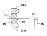
制御部50は、初期位置CORでは、測定子281の先端方向が右リムRIRの下側のクランプピン230a,230bに向くように回転ユニット260を回転させる。また、図9に示すように、制御部50は、Z移動ユニット220(モータ225)の駆動を制御し、測定子281の先端がクランプピン230a,230bの中央位置Hcに位置するように、測定子保持ユニット250を上昇(Z方向に移動)させる。図9は、初期測定開始点でのZ方向のリムの断面図である。続いて、制御部50は、Y移動ユニット230(モータ235)の駆動を制御し、初期位置CORに置かれた測定子281がリムに接触するように測定子保持ユニット250(測定子281)をリム側に移動させる。リムのヤゲン溝RVがリム前後幅の中央にある場合は、測定子281の先端はヤゲン溝RVに挿入される。そして、測定子281の先端がリムに接触し、さらに測定子保持ユニット250がリム側に移動されることにより、測定子軸282が方向Hrに傾斜される。測定子軸282が初期状態から傾斜したことはエンコーダ285によって検出され、その検出結果により測定子281がリムに接触したことが検知される。初期の測定開始点では、測定子軸282が方向Hrに所定角度(8度)傾斜するまで測定子保持ユニット250が移動される。測定子軸282が方向Hrに8度以上傾斜されると、規制機構295が解除され、VHユニット280(測定子281)は、Z方向の可動範囲内でZ方向に自由に移動可能にされる。
At the initial position COR, the
本装置の測定ユニット200の構成例では、リムの動径方向の測定時、制御部50は、測定開始後(測定済み)の動径情報に基づいてリムの未測定部分の動径変化を予測し、未測定部分の動径変化に沿って測定子281の先端が移動するように測定子保持ユニット250を移動させるXY位置を決定し、決定したXY位置に従って移動ユニット210の各モータの駆動を制御する。これにより、リムの変化に対して測定子281が滑らかに追従され、リムの動径を精度良く測定できる。また、リムの垂直方向の測定時、制御部50は測定開始後(測定済み)のZ方向情報に基づいてリムの未測定部分のZ位置変化を予測し、未測定部分のZ位置変化に沿って測定子281の先端が移動するように測定子保持ユニット250を移動させるZ位置を決定し、Z移動ユニット220(モータ225)の駆動を制御する。これにより、Z方向の測定においても、リムの変化に対して測定子281が滑らかに追従され、リムのZ位置を精度良く測定できる。また、リムのZ位置が高くなるに従って、制御部50は測定子軸282の方向Hrへの傾斜角が大きくなるように、移動ユニット210を制御する。これにより、高カーブフレームの測定時に測定子281がリムのヤゲン溝から外れる可能性を低減して測定できる。
In the configuration example of the measurement unit 200 of the present apparatus, when measuring in the radial direction of the rim, the
なお、初期の測定開始時点では、制御部50はリムの動径がX方向に変化しているものとして、測定子281が耳側のX方向に移動するように、測定子保持ユニット250をX方向に移動する。そして、リムの動径変化に追従して測定子281の先端が移動されると、測定子軸282が傾斜される。測定子軸282の傾斜角がエンコーダ285によって検出されることにより、測定子保持ユニット250の基準位置に対する測定子281の先端のXY位置情報が得られる。制御部50は、測定開始時点から所定の測定ポイント数(例えば、全体を1000ポイント測定するとして、5ポイント数)の動径情報が得られたら、次の測定ポイント(未測定ポイント)の変化を予測し、その結果に基づいてリムRIRに測定子281が沿うように、測定子保持ユニット250をXY方向に移動する。また、制御部50は、モータ265の駆動を制御し、回転ベース261を回転することにより、軸LOを中心にVHユニット280を回転する。このときの回転角は、測定子281の先端方向が、予測したリムの動径変化に対して法線方向となるように決定される。あるいは、この回転角は、位置CORを中心にした動径角と法線方向との中間方向に決定されても良い。この動作を繰り返すことにより、リムの全周の動径情報(測定データ)が得られる。なお、測定子保持ユニット250の基準位置に対する測定子281の先端のXY位置情報は、エンコーダ285の検知情報とVHユニット280の回転情報とによって得られる。このXY位置情報と、測定子保持ユニット250をXY移動させるモータ235,245の駆動情報と、によってリムの動径情報(測定データ)が得られる。
Note that at the initial measurement start time, the
また、リムの測定開始後、リムのZ方向への変化に追従して測定子281及び測定子軸282がZ方向に移動される。測定子軸282のZ方向の移動位置がエンコーダ268及びエンコーダ285のZ方向成分で検出されることにより、測定子保持ユニット250の基準位置に対する測定子281のZ位置情報が得られる。このZ位置情報と、測定子保持ユニット250をZ移動させるモータ225の駆動情報と、によってリムのZ位置情報(測定データ)が得られる。
In addition, after starting the measurement of the rim, the
次に、図10のように、リムのヤゲン溝RVがリムの前後幅の中央に対して、前側に偏って形成されている場合の測定動作を説明する。図10は、初期測定開始点でのZ方向のリムの断面図である。前述のように、測定開始信号が入力されると、制御部50は、初期位置CORで中央位置Hcに置かれた測定子281をリム側に移動し、測定子281がリムに接触したことが検知されると、測定子281をX方向の耳側方向又は鼻側方向に移動する。しかし、クランプピン230a,230bの中央位置Hcにヤゲン溝RVが位置していないため、測定子281はヤゲン溝RVに挿入されず、リムの内壁RIeに接触した状態でX方向に移動されることになる。ここで、VHユニット280(測定子281)がリムの幅方向の上方向(リムの後側方向)に向かうような力がバネ267によって与えられているため、測定子281はリムの内壁RIeに沿って上方向に移動され、リムからは外れてしまう測定エラーをなる。なお、VHユニット280(測定子281)がリムの前側方向に向かうような力がバネ267に与えられている場合であっても、測定子281が移動途中でヤゲン溝RVに挿入されるか、或いはリムからは外れてしまい、測定エラーとなる。
Next, as shown in FIG. 10, the measurement operation in the case where the bevel groove RV of the rim is formed to be biased to the front side with respect to the center of the front-rear width of the rim will be described. FIG. 10 is a cross-sectional view of the rim in the Z direction at the initial measurement start point. As described above, when the measurement start signal is input, the
初期測定開始点で測定子281がヤゲン溝RVに挿入されずに測定が開始された測定エラーであることは、初期測定開始点から所定の動径範囲RS(図示を略す)で得られた測定データに急峻な変化(不連続とみなせる異常データ)がある否かを基に判定することができる。すなわち、測定子281がヤゲン溝RVに挿入された状態で測定が開始されたときには、動径方向及びZ方向の測定データは連続的に徐々に変化する。これに対して、測定子281がヤゲン溝RVに挿入されず、リムの内壁RIeに接触した状態で測定が開始され、前述のように測定途中で測定子281がリムから外れると(又はヤゲン溝RVに挿入されると)、動径方向及びZ方向の測定データの少なくとも一方に急峻な変化が現れる。
The measurement error obtained when the measurement is started without the
例えば、制御部50は、測定データの動径長について、位置CORを基準にした0.36度ステップの測定点間で1mm以上変化している場合に測定不良であると判定する。また、制御部50は、測定データのZ位置について、3ポイント前(1.08度戻った位置)から0.3mm以上変化している場合にも、測定不良である判定する。この測定不良の判定は、初期測定開始点から所定の動径範囲RS(例えば、位置CORを基準にして初期測定開始点から36度の範囲又は初期測定開始点からX方向へ10mmの範囲)に設定されている。
For example, the
制御部50は、上記のように初期測定開始点から所定の動径範囲RSで測定にエラーが有ると判定したときには、初期測定開始点で測定子281がヤゲン溝RVに挿入されない状態で測定が開始された測定エラーであると判断し、測定を一旦中断して再測定モードに自動的に移行する。
When the
再測定モードを説明する。制御部50は、測定子281を一旦初期位置CORに戻した後、最初の測定動作と同じく、測定子281をリム側に移動する。制御部50は、測定子281がリムに接触したことがエンコーダ285によって検知されると、規制機構295によって測定子281のZ方向の移動が規制される範囲で測定子軸282が傾斜するように測定子保持ユニット250を移動する。例えば、規制機構295の規制が完全に解除される測定子軸282の傾斜量(8度)より小さな傾斜量(例えば、5度)まで、測定子軸282が方向Hrに初期状態から傾斜するように、測定子保持ユニット250がリム側に移動される。この状態では、VHユニット280(測定子281)のZ方向(上下方向)への移動可能量は下限から2mm上方向までに制限される。これにより、リムの内壁RIeに接触した測定子281のZ方向の位置は、リム前後幅の中央位置にほぼ維持される。そして、制御部50は、測定子281のZ方向の位置がほほ維持された状態で移動ユニット210の駆動を制御し、測定子保持ユニット250(測定子281)を初期測定開始点からリムの耳側方向に移動する。又は、制御部50は、モータ225の駆動を制御し、測定子保持ユニット250を下方向(リムの前側方向)に移動することにより、測定子281のZ方向の位置がリムの前側方向に向かわせつつ、測定子保持ユニット250(測定子281)を初期測定開始点からリムの耳側方向に移動する。
The remeasurement mode will be described. The
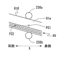
ここで、フレーム保持ユニット100に保持された一般的な高カーブフレームFのリム及びヤゲン溝RVは、図11に示すように、リムRIRの耳側方向に向かって徐々に上がっている。このため、測定子281がX方向のりムの耳側方向に移動されると、測定子281は、何時かはヤゲン溝RVに挿入されることになる。図11は、リムを初期位置CORから見た図であり、リム及びヤゲン溝RVの傾斜を示す図である。図11において、PS1は初期測定開始点での測定子281の先端位置を示し、PS2は測定子281がヤゲン溝RVに挿入された位置を示す。
Here, as shown in FIG. 11, the rim and the bevel groove RV of the general high curve frame F held by the
図11のように、測定子281がリムの内壁RIeに接触して移動されている間の各測定点の測定データ(動径情報)は徐々に変化するが、測定子281が内壁RIeの接触位置からヤゲン溝RVに入ると、測定データの動径情報は急峻に変化する。制御部50は、動径情報に急峻な変化があった段階を測定途中で測定子281がヤゲン溝RVに挿入された位置であると判断する。さらに好ましくは、位置PS2は動径情報の急峻な変化以降において、動径情報及びZ方向のZ位置情報が徐々に変換しているか否かに基づいて判断される。そして、制御部50は、測定途中で測定子281がヤゲン溝RVに挿入されたと判断したときは、初期測定開始点PS1からの測定データを不採用とし(測定結果として採用せずに)、新たに測定データの取得を開始する。
As shown in FIG. 11, the measurement data (radial radius information) at each measurement point changes gradually while the
例えば、制御部50は、測定子281がヤゲン溝RVに挿入された位置PS2から初めの測定開始点(クランプピン230a,230bの位置)までヤゲン溝RVに沿って戻るように移動ユニット210を制御し、再び初期の測定開始点からリムの耳側方向又は鼻側方向に測定子281を移動させてリムの全周形状の測定データを得るように移動ユニット210を制御する。この測定動作の制御は前述と同様であるので、省略する。
For example, the
また、測定途中で測定子281がヤゲン溝RVに挿入された判断した後の測定は次のようにしても良い。制御部50は、測定子281がヤゲン溝RVに挿入された位置PS2を新たな測定開始点として、ヤゲン溝RVの変化に沿って測定子281を移動させ、リムの全周の測定データを得るように移動ユニット210を制御する。なお、測定子281がリムのヤゲン溝RVに挿入されている場合には、測定子281の移動方向はリムの耳側方向及び鼻側方向の何れであっても良い。
Further, the measurement after determining that the
右リムRIRの全周の測定データはメモリ51(記憶手段)に記憶される。制御部50は、右リムRIRの測定が終了すると、続けて左リムRILを測定するために、移動ユニット210を制御し、左リムRIL側に設定された初期位置COL(右リムRIR側の位置CORと同様な方法で設定された位置)に測定子281を移動させた後、初期位置COLから左リムRILの測定開始点に測定子281を移動させる。このとき、制御部50は、測定子281のZ方向の位置をクランプピン230a,230bの中央位置Hcに設定するのでは無く、メモリ51に記憶されている右リムRIRの測定データに基づき、測定子281のZ方向位置を決定する。すなわち、制御部50は、右リムRIRがクランプピン230a,230bでクランプされた位置(動径の初期測定点)でのZ方向位置データをメモリ51から読み出し、これと同じZ方向位置に測定子281を移動する。これにより、左リムRILの初期測定開始点(クランプピン230a,230bの位置)に測定子281を移動させたとき、初めから高確率でヤゲン溝RVに測定子281が挿入される。初期測定開始点で測定子281がヤゲン溝RVに挿入されていれば、通常の測定動作でリムの全周が測定される。
The measurement data of the entire circumference of the right rim RIR is stored in the memory 51 (storage means). When the measurement of the right rim RIR is completed, the
なお、左リムRILの測定時においても、初期測定開始点でヤゲン溝RVに測定子281が挿入されていなかった場合、動径範囲RSで測定データに急峻な変化があれば、制御部50は測定開始点で測定子281がヤゲン溝RVに挿入されなかった測定不良であると判定し、右リムRIRと同様な制御を行う。右リムRIRと左リムRILの測定の順番は、上記に限られず、左リムRILの測定は先に行われても良い。
Even when the left rim RIL is measured, if the
以上のようにして、ヤゲン溝RVがリムの前後幅の中央ではなく、前側に偏って形成されている場合にも、操作者の補助を必要とすることなく、自動的にヤゲン溝RVの測定子281が挿入された状態でのリムの全周形状の測定データが得られる。これにより、測定の効率化が図られる。
As described above, even when the bevel groove RV is formed not on the center of the front and rear width of the rim but on the front side, the measurement of the bevel groove RV is automatically performed without requiring the assistance of the operator. Measurement data of the entire circumference of the rim in a state where the
なお、上記の例では、リムの内壁RIeに接触した測定子281を上方向(リムの後側方向)に向かわせるための移動力を与える構成の場合を中心に説明したが、測定子281を下方向(リムの前側方向)に向かわせるための移動力を与える構成でも良い。
In the above example, the description has focused on the configuration in which a moving force is provided to direct the measuring
なお、測定子281を下方向(リムの前側方向)に向かわせるための移動力を与える構成の場合、測定子281がリムの内壁RIeに接触した後、測定子281は下方向(リムの前側)に向かうため、測定子281の所期測定開始点より下方向(リムの前側方向)に位置するヤゲン溝RVに高い確率で挿入されることになる。したがって、測定開始時に測定エラーが有ると判定された後の測定動作については、前述のような測定子281を一旦リムから離脱させ、再度、測定子281をヤゲン溝RVに挿入する動作を不要とすることができる。測定子281がヤゲン溝RVに挿入されているか否かは、最初に測定エラーであると判定したときに得られた測定データ及びその後に得られた測定データの少なくとも一方に基づいて判断することができる。
In the case of a configuration in which a moving force is applied to direct the measuring
例えば、最初に測定エラーであると判定したときに得られた測定データを使用して判断するときは、測定データに含まれる動径情報及びZ方向の位置情報の少なくとも一方が所定値以上で有るか否かに基づいて判断できる。測定子281がリムの内壁RIeに接触した後に測定子281がヤゲン溝RVに挿入されずにリムから外れたときには、測定子281の動径方向へ移動限界まで大きく移動し、また、Z方向にも移動限界まで大きく移動する。これに対して、測定子281がヤゲン溝RVに挿入されたときには、測定子281の動径方向の変化はヤゲン溝RVに当たって止まる。このときの動径方向の変化を5mm等の所定値としておけば、測定子281がヤゲン溝RVに挿入されたか否かを判断できる。同様に、Z方向についても測定子281が3mm等の所定値以上に移動したか否かで、測定子281がヤゲン溝RVに挿入されたか否かを判断できる。
For example, when the determination is made using the measurement data obtained when the measurement error is first determined, at least one of the radial information and the position information in the Z direction included in the measurement data is greater than or equal to a predetermined value. It can be determined based on whether or not. When the
最初に測定エラーであると判定した後に得られた測定データ(以下、継続測定データという)を使用するときは、継続測定データに含まれる動径情報及び垂直方向情報の少なくとも一方に急峻な変化が有るか否かに基づいて測定子がヤゲン溝に挿入されたか否かを判断することができる。例えば、前述のような条件で測定エラーか否かを判定した後も引き続き測定子281をX方向に移動し、所定の動径範囲(例えば、前述の動径範囲RSと同様な範囲)の動径情報及びZ位置情報に急峻な変化が有るか否かに基づいて判断する。すなわち、測定子281がヤゲン溝RVに挿入されていれば、継続測定データの動径情報及びZ位置情報は徐々に変化し、急峻な変化は出現しなくなる。
When using measurement data obtained after first determining that there is a measurement error (hereinafter referred to as continuous measurement data), there is a steep change in at least one of radial information and vertical direction information included in the continuous measurement data. Based on whether or not there is a probe, it can be determined whether or not the probe has been inserted into the bevel groove. For example, after determining whether or not there is a measurement error under the conditions described above, the
以上のように測定子281がヤゲン溝RVに挿入されたと判断できれば、前述の同様にヤゲン溝RVの変化に沿って測定子281を移動させることにより、リムの全周の測定データを得ることができる。
If it can be determined that the
なお、測定子281がヤゲン溝RVに挿入されたと判断された後も、制御部50は測定データに急峻な変化が有るか否かを監視し、所定の急峻な変化はあれば、測定エラーとして測定を停止する。この場合、操作者は測定子281がヤゲン溝RVから外れたことによるエラーか確認し、ヤゲン溝RVから外れたことによるエラーであれば、従来と同じく、指で測定子をヤゲン溝に挿入する作業を行った上で、リムの測定を開始する対応を取れば良い。
Even after it is determined that the measuring
なお、測定ユニット200の構成は、図4〜図7に示されたものに限られない。特開2000−314617号と同じような構成であっても、本発明を適用できる。特開2000−314617号の構成においては、測定子はモータの駆動によってZ方向に移動される構成である。前述のような再測定モードに移行した場合に、先の実施例で説明した規制機構295はモータ(測定子をZ方向に移動するモータ)の駆動に置き換えることができる。すなわち、制御部は、図11にようにリムの内壁RIeに接触した測定子281の位置PS1のZ方向位置をほぼ維持又はリムの前側に向かうようにモータの駆動を制御しつつ、測定子281をX方向におけるリムの耳側方向に移動する。これによって測定子281がヤゲン溝RVに挿入されるようになる。測定子281がヤゲン溝RVに挿入された後は、初期測定開始点PS1からの測定データを不採用とし、前述の例と同様な動作でリム全周の測定データを得ることができる。このように本件発明は種々の変容が可能であり、これらも本件発明に含まれる。
In addition, the structure of the measurement unit 200 is not restricted to what was shown by FIGS. The present invention can be applied even with a configuration similar to that of Japanese Patent Laid-Open No. 2000-314617. In the configuration of Japanese Patent Laid-Open No. 2000-314617, the probe is moved in the Z direction by driving a motor. When shifting to the re-measurement mode as described above, the
50 制御部
51 メモリ
100 フレーム保持ユニット
200 測定ユニット
210 移動ユニット
250 測定子保持ユニット
260 回転ユニット
280 垂直傾斜保持ユニット
281 測定子
282 測定子軸
295 規制機構
DESCRIPTION OF
Claims (3)
前記制御手段は、リムの測定開始点から前記測定子を移動させることによって得られた測定データの変化に基づき、測定開始点で前記測定子が前記ヤゲン溝に挿入された第1状態と、測定開始点で前記測定子が前記ヤゲン溝に挿入されていない第2状態と、の何れの状態で測定が開始されたかを判定し、前記第2状態で測定が開始されたと判定したときには再測定に移行し、再測定では、前記第1状態で測定が開始されたときに行う前記移動手段の制御に対して少なくとも一部の動作を変更する制御であって、前記測定子をリムから離脱させた後、リムの前後幅のほぼ中央位置に前記測定子を接触させるように前記移動手段を制御し、そして、(a)リムの前後幅方向における前記測定子の接触位置を維持した状態で、リムの耳側方向に測定子を移動させるように前記移動手段を制御するか、又は(b)測定子をリムの前側方向に向かわせつつ、リムの耳側方向に測定子を移動させるように前記移動手段を制御するか、の何れかを行うことを特徴とする眼鏡枠形状測定装置。 Frame holding means for holding the front and rear sides of the rim of the spectacle frame at predetermined positions, a measuring element inserted into the bevel groove of the rim, and a moving means for moving the measuring element along the bevel groove of the rim. Detecting means for detecting the position of the probe moved along the bevel groove; and control means for controlling the moving means to obtain measurement data of the shape of the rim based on the detection result of the detecting means. In the spectacle frame shape measuring apparatus provided,
The control means, based on a change in measurement data obtained by moving the probe from the measurement start point of the rim, a first state in which the probe is inserted into the bevel groove at the measurement start point, and a measurement It is determined in which state the measurement is started in the second state where the probe is not inserted in the bevel groove at the start point, and when it is determined that the measurement is started in the second state, re-measurement is performed. In the re-measurement, the control is a control for changing at least a part of the operation of the moving means performed when the measurement is started in the first state, and the measuring element is detached from the rim. Thereafter, the moving means is controlled so as to bring the measuring element into contact with a substantially central position of the front and rear width of the rim. Measure in the ear direction Or (b) controlling the moving means to move the probe in the ear-side direction of the rim while moving the probe toward the front side of the rim, or A spectacle frame shape measuring apparatus that performs any of the above.
前記制御手段は、再測定では、再測定で得られた測定データの変化に基づき、前記測定子の移動途中で前記測定子が前記ヤゲン溝に挿入されたか否かを判定し、該判定によって前記測定子が前記ヤゲン溝に挿入されたと判定された地点から前記測定子を前記ヤゲン溝に沿って移動させ、リムの全周形状の測定データを得るように前記移動手段を制御することを特徴とする眼鏡枠形状測定装置。 In the spectacle frame shape measuring apparatus according to claim 1,
In the remeasurement, the control means determines whether the probe is inserted into the bevel groove during the movement of the probe based on a change in measurement data obtained by the remeasurement. Moving the measuring element along the bevel groove from a point where it is determined that the measuring element has been inserted into the bevel groove, and controlling the moving means to obtain measurement data of the entire circumference of the rim. Eyeglass frame shape measuring device.
左右リムの一方の第1リムを測定した後に他方の第2リムを連続して測定するための連続測定開始信号を入力するための測定開始信号入力手段と、
リムの測定データを記憶する記憶手段と、を備え、
前記制御手段は、第1リムの測定では、リムの測定開始点から前記測定子を移動させることによって得られた測定データの変化に基づき、測定開始点で前記測定子が前記ヤゲン溝に挿入された第1状態と、測定開始点で前記測定子が前記ヤゲン溝に挿入されていない第2状態と、の何れの状態で測定が開始されたかを判定し、前記第2状態で測定が開始されたと判定したときには再測定に移行し、再測定では、前記第1状態で測定が開始されたときに行う前記移動手段の制御に対して少なくとも一部の動作を変更する制御であって、前記測定子をリムから離脱させた後、リムの前後幅のほぼ中央位置に前記測定子を接触させるように前記移動手段を制御し、そして、(a)リムの前後幅方向における前記測定子の接触位置を維持した状態で、リムの耳側方向に測定子を移動させるように前記移動手段を制御するか、又は(b)測定子をリムの前側方向に向かわせつつ、リムの耳側方向に測定子を移動させるように前記移動手段を制御するか、の何れかを行い、さらに、前記連続測定開始信号が入力されているときには、第1リムの測定終了後に、前記記憶手段に記憶された第1リムの測定データに基づき、第2リムの初期測定開始点に測定子をリム側に移動するときのリムの前後幅方向における測定子の位置を決定することを特徴とする眼鏡枠形状測定装置。 Frame holding means for holding the front and rear sides of the rim of the spectacle frame at predetermined positions, a measuring element inserted into the bevel groove of the rim, and a moving means for moving the measuring element along the bevel groove of the rim. Detecting means for detecting the position of the probe moved along the bevel groove; and control means for controlling the moving means to obtain measurement data of the shape of the rim based on the detection result of the detecting means. In the spectacle frame shape measuring apparatus provided,
Measurement start signal input means for inputting a continuous measurement start signal for continuously measuring the other second rim after measuring one first rim of the left and right rims;
Storage means for storing measurement data of the rim,
In the measurement of the first rim, the control means inserts the probe into the bevel groove at the measurement start point based on a change in measurement data obtained by moving the probe from the measurement start point of the rim. The first state and the second state in which the measuring element is not inserted into the bevel groove at the measurement start point are determined, and the measurement is started in the second state. When it is determined that the measurement has been performed, the process proceeds to re-measurement, and the re-measurement is a control that changes at least a part of the operation with respect to the control of the moving unit that is performed when the measurement is started in the first state. After the child is detached from the rim, the moving means is controlled so that the measuring element is brought into contact with a substantially central position of the front-rear width of the rim, and (a) the contact position of the measuring element in the front-rear width direction of the rim In a state where The moving means is controlled to move the probe in the ear side direction of the rim, or (b) the probe is moved in the ear side direction of the rim while the probe is directed toward the front side of the rim. In addition, when the continuous measurement start signal is input, the measurement data of the first rim stored in the storage means is stored after the measurement of the first rim is completed. The spectacle frame shape measuring apparatus characterized in that, based on the initial measurement start point of the second rim, the position of the measuring element in the longitudinal direction of the rim when the measuring element is moved to the rim side is determined.
Priority Applications (3)
| Application Number | Priority Date | Filing Date | Title |
|---|---|---|---|
| JP2012195457A JP6172430B2 (en) | 2012-09-05 | 2012-09-05 | Eyeglass frame shape measuring device |
| US14/017,755 US9080853B2 (en) | 2012-09-05 | 2013-09-04 | Eyeglass frame shape measuring apparatus |
| EP20130183074 EP2706323B1 (en) | 2012-09-05 | 2013-09-05 | Eyeglass frame shape measuring apparatus |
Applications Claiming Priority (1)
| Application Number | Priority Date | Filing Date | Title |
|---|---|---|---|
| JP2012195457A JP6172430B2 (en) | 2012-09-05 | 2012-09-05 | Eyeglass frame shape measuring device |
Publications (3)
| Publication Number | Publication Date |
|---|---|
| JP2014052222A JP2014052222A (en) | 2014-03-20 |
| JP2014052222A5 JP2014052222A5 (en) | 2015-10-29 |
| JP6172430B2 true JP6172430B2 (en) | 2017-08-02 |
Family
ID=49084919
Family Applications (1)
| Application Number | Title | Priority Date | Filing Date |
|---|---|---|---|
| JP2012195457A Active JP6172430B2 (en) | 2012-09-05 | 2012-09-05 | Eyeglass frame shape measuring device |
Country Status (3)
| Country | Link |
|---|---|
| US (1) | US9080853B2 (en) |
| EP (1) | EP2706323B1 (en) |
| JP (1) | JP6172430B2 (en) |
Families Citing this family (7)
| Publication number | Priority date | Publication date | Assignee | Title |
|---|---|---|---|---|
| US9535269B2 (en) * | 2013-06-24 | 2017-01-03 | Nidek Co., Ltd. | Eyeglass frame shape measuring apparatus |
| CN107179032A (en) * | 2016-03-11 | 2017-09-19 | 上海强精金属制品有限公司 | A kind of door for microwave oven detection means |
| US11022430B2 (en) * | 2017-09-05 | 2021-06-01 | Nidek Co., Ltd. | Eyeglass frame shape measurement device and storage medium |
| JP7052567B2 (en) | 2018-05-31 | 2022-04-12 | 株式会社ニデック | Eyeglass lens processing control data acquisition device |
| JP7276050B2 (en) * | 2019-09-30 | 2023-05-18 | 株式会社ニデック | Spectacle frame shape measuring device and lens processing device |
| EP3978863A1 (en) * | 2020-09-30 | 2022-04-06 | Nidek Co., Ltd. | Eyeglass frame shape measurement apparatus and control program for eyeglass frame shape measurement apparatus |
| CN112123800B (en) * | 2020-10-16 | 2022-07-01 | 深圳市华成利工数控设备有限公司 | Glasses leg pin inserting equipment |
Family Cites Families (15)
| Publication number | Priority date | Publication date | Assignee | Title |
|---|---|---|---|---|
| US5333412A (en) * | 1990-08-09 | 1994-08-02 | Nidek Co., Ltd. | Apparatus for and method of obtaining processing information for fitting lenses in eyeglasses frame and eyeglasses grinding machine |
| US5121550A (en) * | 1990-12-03 | 1992-06-16 | Gerber Optial, Inc. | Automatic surface tracer |
| JP2578354Y2 (en) * | 1993-01-08 | 1998-08-13 | ホーヤ株式会社 | Eyeglass lens frame shape measuring device |
| JPH0843071A (en) * | 1994-07-27 | 1996-02-16 | Topcon Corp | Apparatus for measuring shape of lens frame |
| JP3695988B2 (en) | 1999-04-30 | 2005-09-14 | 株式会社ニデック | Eyeglass frame shape measuring device |
| FR2870934B1 (en) | 2004-05-28 | 2006-09-08 | Essilor Int | CONTOUR READING APPARATUS COMPRISING A ROTATING MOBILE PROBE |
| FR2893723B1 (en) * | 2005-11-23 | 2008-02-01 | Essilor Int | SCREEN READING APPARATUS FOR EYEGLASS MOUNT CIRCUIT DRAGER |
| FR2910136B1 (en) | 2006-12-18 | 2009-02-27 | Essilor Int | METHOD FOR CORRECTING THE GEOMETRY OF A SPINNING LAYER APPROACHING A LONGITUDINAL STRAND OF A GOGGLE MOUNT DRAWER AND METHOD OF ACQUIRING THE GEOMETRY OF A CONTOUR OF SUCH A DRAWER |
| JP4920514B2 (en) | 2007-07-04 | 2012-04-18 | 株式会社ニデック | Ball shape measuring device |
| FR2934903B1 (en) | 2008-08-07 | 2012-04-06 | Briot Int | APPARATUS FOR READING THE GEOMETRY OF A DRAWER. |
| FR2950162B1 (en) * | 2009-09-14 | 2011-10-07 | Essilor Int | METHOD FOR PRODUCING A DETOURING SETTING OF AN OPHTHALMIC LENS |
| JP5586930B2 (en) | 2009-12-09 | 2014-09-10 | 株式会社ニデック | Eyeglass frame shape measuring device |
| JP5562624B2 (en) | 2009-12-09 | 2014-07-30 | 株式会社ニデック | Eyeglass frame shape measuring device |
| FR2983316B1 (en) * | 2011-11-30 | 2014-06-27 | Essilor Int | PROCESS FOR PREPARING AN OPHTHALMIC LENS |
| US9535269B2 (en) * | 2013-06-24 | 2017-01-03 | Nidek Co., Ltd. | Eyeglass frame shape measuring apparatus |
-
2012
- 2012-09-05 JP JP2012195457A patent/JP6172430B2/en active Active
-
2013
- 2013-09-04 US US14/017,755 patent/US9080853B2/en active Active
- 2013-09-05 EP EP20130183074 patent/EP2706323B1/en active Active
Also Published As
| Publication number | Publication date |
|---|---|
| EP2706323B1 (en) | 2015-03-25 |
| EP2706323A1 (en) | 2014-03-12 |
| US9080853B2 (en) | 2015-07-14 |
| JP2014052222A (en) | 2014-03-20 |
| US20140059871A1 (en) | 2014-03-06 |
Similar Documents
| Publication | Publication Date | Title |
|---|---|---|
| JP6172430B2 (en) | Eyeglass frame shape measuring device | |
| JP5562624B2 (en) | Eyeglass frame shape measuring device | |
| US8844146B2 (en) | Eyeglass frame shape measurement device | |
| JP5586930B2 (en) | Eyeglass frame shape measuring device | |
| JP6080002B2 (en) | Eyeglass lens processing equipment | |
| US6719609B2 (en) | Eyeglass lens processing apparatus | |
| JP2001105293A (en) | Spherical shape measuring device and glass lens working device having the same, and calibration method for spherical shape measuring device | |
| JP3839185B2 (en) | Eyeglass lens processing equipment | |
| KR20130135175A (en) | Eyeglass lens processing apparatus | |
| US5890949A (en) | Eyeglass lens grinding machine | |
| KR101952447B1 (en) | Device for measuring the shape of eyeglasses frame | |
| JP6093506B2 (en) | Surface texture measuring machine and surface texture measuring method | |
| JP5198978B2 (en) | Eyeglass frame shape measuring device | |
| JP6071103B2 (en) | Eyeglass frame shape measuring device | |
| JP6102850B2 (en) | Method and apparatus for detecting Z-axis backlash amount of machining center | |
| US9144876B2 (en) | Eyeglass lens processing apparatus | |
| JP2013068439A (en) | Glass frame shape measuring apparatus | |
| JP2013068488A (en) | Glass frame shape measuring apparatus | |
| JP6254417B2 (en) | measuring device | |
| JP2000343394A (en) | Ball type shape measuring device and spectacle lens machining apparatus having it | |
| JP6319627B2 (en) | Eyeglass lens peripheral shape measuring apparatus and spectacle lens peripheral shape measuring method | |
| JP2002192420A (en) | Band sawing machine | |
| JP7084062B1 (en) | Eyeglass frame shape measuring device | |
| JP2015196215A (en) | Spectacle lens peripheral edge shape measuring apparatus and spectacle lens peripheral edge shape measuring program | |
| KR100881031B1 (en) | Tracer for correctly reading groove position of the spectacle |
Legal Events
| Date | Code | Title | Description |
|---|---|---|---|
| A521 | Request for written amendment filed |
Free format text: JAPANESE INTERMEDIATE CODE: A523 Effective date: 20150903 |
|
| A621 | Written request for application examination |
Free format text: JAPANESE INTERMEDIATE CODE: A621 Effective date: 20150903 |
|
| A977 | Report on retrieval |
Free format text: JAPANESE INTERMEDIATE CODE: A971007 Effective date: 20160728 |
|
| A131 | Notification of reasons for refusal |
Free format text: JAPANESE INTERMEDIATE CODE: A131 Effective date: 20160809 |
|
| A521 | Request for written amendment filed |
Free format text: JAPANESE INTERMEDIATE CODE: A523 Effective date: 20161011 |
|
| A131 | Notification of reasons for refusal |
Free format text: JAPANESE INTERMEDIATE CODE: A131 Effective date: 20170314 |
|
| A521 | Request for written amendment filed |
Free format text: JAPANESE INTERMEDIATE CODE: A523 Effective date: 20170512 |
|
| TRDD | Decision of grant or rejection written | ||
| A01 | Written decision to grant a patent or to grant a registration (utility model) |
Free format text: JAPANESE INTERMEDIATE CODE: A01 Effective date: 20170607 |
|
| A61 | First payment of annual fees (during grant procedure) |
Free format text: JAPANESE INTERMEDIATE CODE: A61 Effective date: 20170620 |
|
| R150 | Certificate of patent or registration of utility model |
Ref document number: 6172430 Country of ref document: JP Free format text: JAPANESE INTERMEDIATE CODE: R150 |
|
| R250 | Receipt of annual fees |
Free format text: JAPANESE INTERMEDIATE CODE: R250 |
|
| R250 | Receipt of annual fees |
Free format text: JAPANESE INTERMEDIATE CODE: R250 |
|
| R250 | Receipt of annual fees |
Free format text: JAPANESE INTERMEDIATE CODE: R250 |
|
| R250 | Receipt of annual fees |
Free format text: JAPANESE INTERMEDIATE CODE: R250 |