JP5584064B2 - Macro lens - Google Patents
Macro lens Download PDFInfo
- Publication number
- JP5584064B2 JP5584064B2 JP2010204605A JP2010204605A JP5584064B2 JP 5584064 B2 JP5584064 B2 JP 5584064B2 JP 2010204605 A JP2010204605 A JP 2010204605A JP 2010204605 A JP2010204605 A JP 2010204605A JP 5584064 B2 JP5584064 B2 JP 5584064B2
- Authority
- JP
- Japan
- Prior art keywords
- lens
- lens component
- component
- refractive power
- macro
- Prior art date
- Legal status (The legal status is an assumption and is not a legal conclusion. Google has not performed a legal analysis and makes no representation as to the accuracy of the status listed.)
- Active
Links
Images


Description
本発明はスチルカメラやビデオカメラ等に好適なマクロレンズに関する。特に撮影倍率1:2以上の高い倍率での撮影が可能で、かつ防振機構を備えた、対角線画角20°〜25°程度のマクロレンズに関する。 The present invention relates to a macro lens suitable for a still camera or a video camera. In particular, the present invention relates to a macro lens having a diagonal angle of view of about 20 ° to 25 ° and capable of shooting at a high magnification of 1: 2 or more and provided with a vibration isolation mechanism.
従来、撮影倍率が1:2から1:1程度の近距離撮影を行うことを主な目的とした、いわゆるマクロレンズと呼ばれる光学系がある。 2. Description of the Related Art Conventionally, there is an optical system called a so-called macro lens whose main purpose is to perform short-distance photographing with a photographing magnification of about 1: 2 to 1: 1.
多くのマクロレンズは無限遠物体から撮影倍率が1:1程度の近距離物体まで連続的に合焦可能であり、撮影距離の全域で収差変動が少なく、高い結像性能を発揮するように設計される。 Many macro lenses can focus continuously from an object at infinity to a close object with a shooting magnification of about 1: 1, and are designed to exhibit high imaging performance with little aberration variation over the entire shooting distance. Is done.
従来、フォーカシングに伴う収差変動を極力抑制するため、フォーカシング時に2つ以上のレンズ群が移動する、いわゆるフローティングを行うことで、撮影距離全域での非点収差の変動を抑制することが一般に行われるようになった。 Conventionally, in order to suppress aberration fluctuations due to focusing as much as possible, it is generally performed to suppress fluctuations in astigmatism over the entire photographing distance by performing so-called floating in which two or more lens groups move during focusing. It became so.
また、従来は、最も物体側のレンズ群をフォーカシング時に移動するためフォーカシングによってレンズ全長が変わってしまうフロントフォーカスが採用されていたが、近年では、最も物体側のレンズ群をフォーカシング時に固定とするインナーフォーカスが採用され、フォーカシングによって全長が変わらないために操作性が向上したマクロレンズが提案されてきた。 Conventionally, the front focus, in which the entire lens length is changed by focusing because the most object side lens group is moved during focusing, has been adopted in recent years. A macro lens has been proposed that employs focus and has improved operability because the overall length does not change due to focusing.
上記のような、インナーフォーカスを採用し、かつ、フォーカシング時にはフローティングを行うマクロレンズの代表的な例として、物体側から順に、フォーカシング時に固定の正の屈折力の第1レンズ群、負の屈折力の第2レンズ群、フォーカシング時に固定の開口絞り、正の屈折力の第3レンズ群、フォーカシング時に固定の負の屈折力の第4レンズ群を備え、無限遠から近距離へのフォーカシング時に第2レンズ群が像側へ、第3レンズ群が物体側へ、それぞれ移動する構成が知られている。 As a typical example of a macro lens that adopts the inner focus as described above and that floats during focusing, in order from the object side, a first lens unit having a fixed positive refractive power during focusing, a negative refractive power Second lens group, a fixed aperture stop during focusing, a third lens group having positive refractive power, and a fourth lens group having negative refractive power fixed during focusing, and the second lens during focusing from infinity to a short distance A configuration is known in which the group moves to the image side and the third lens group moves to the object side.
ところで、マクロレンズにおいては、撮影倍率が大きくなるに従って、撮影者の手ブレに因る像ブレへの影響が大きくなることが知られている。 By the way, it is known that in the macro lens, as the photographing magnification increases, the influence on the image blur due to the camera shake of the photographer increases.
撮影倍率が高い場合には被写界深度が極めて浅くなるため、絞りを絞って被写界深度を深くして撮影する機会が多いが、被写体の照度が同じであればより露出時間を長くする必要がある。 When the shooting magnification is high, the depth of field becomes extremely shallow, so there are many opportunities to shoot with the aperture narrowed down to increase the depth of field. There is a need.
そのため、撮影倍率が高い場合には、記録される像のシャープネスが像ブレによって損なわれることが多かった。また、像ブレを防止するためにカメラを三脚に固定して撮影することが多く行われてきたが、三脚は携行に難が有る。更に、近年では三脚の使用を禁止された撮影場所が増えてきている。 For this reason, when the photographing magnification is high, the sharpness of the recorded image is often impaired by image blurring. Moreover, in order to prevent image blurring, the camera is often fixed to a tripod for shooting, but the tripod is difficult to carry. Furthermore, in recent years, there are an increasing number of shooting locations where the use of tripods is prohibited.
そのため、レンズ系の一部を光軸と直交する方向にシフトさせることによって、像ブレの補正(防振)を行い、インナーフォーカスでフローティングを行う、等倍程度までの撮影が可能な光学系が特許文献1から特許文献3などに提案されている。
For this reason, an optical system capable of shooting up to approximately the same magnification, which performs image blur correction (anti-vibration) by shifting a part of the lens system in a direction perpendicular to the optical axis and floating with an inner focus, is provided.
マクロレンズにおいては、フォーカシングに伴う諸収差の変動を抑制することが課題となる。 In a macro lens, it is a problem to suppress fluctuations in various aberrations accompanying focusing.
マクロレンズでは、無限遠から近距離へのフォーカシングに伴って軸上および倍率色収差が拡大され、非点収差に加えてコマ収差等の変動が大きくなりがちである。これらは画質低下の原因となってしまうため、収差変動の少ない構成をとる必要がある。 In a macro lens, axial and lateral chromatic aberrations are enlarged with focusing from infinity to a short distance, and fluctuations such as coma in addition to astigmatism tend to increase. Since these cause deterioration of image quality, it is necessary to adopt a configuration with little aberration fluctuation.
更に、レンズ系の一部のレンズ群を光軸と直交する方向にシフトして像ブレの補正を行う場合においては、防振群をシフトした際に非点収差の変動が起こるため、標準状態において従来よりも高度な非点収差の補正を行ない、更に防振状態のときの像面の変動を十分に抑制する必要がある。また、製造誤差による非点収差やコマ収差の変動も可能な限り抑制する必要がある。 Furthermore, when correcting image blur by shifting some lens groups in the lens system in the direction orthogonal to the optical axis, astigmatism fluctuations occur when the image stabilization group is shifted. Therefore, it is necessary to correct astigmatism higher than that in the prior art, and to sufficiently suppress fluctuations in the image plane when in a vibration-proof state. It is also necessary to suppress astigmatism and coma fluctuations due to manufacturing errors as much as possible.
特許文献1に記載の光学系は、防振群をシフトした際の像面の変動が極めて大きく、十分な補正が行われていない。
In the optical system described in
特許文献2に記載の光学系は、特に等倍付近において軸上色収差と球面収差が大きく発生してしまう。中でもg線の正の球面収差量が大きく発生しており、結果、青色のフレアが顕著に発生してしまう。また、コマ収差の補正が不十分で、更に防振時のコマ収差変動も大きいため、防振時に顕著な片ボケを生じてしまう。
In the optical system described in
特許文献3に記載の光学系は、等倍付近における軸上色収差が改善されているが、フォーカシングに伴うメリジオナル像面の変動が大きく、軸外でのg線のコマ収差が大きく発生して、青色のフレアが大きく発生する等、画質の問題がある。
The optical system described in
本発明は1:2以上の高い倍率での撮影が可能で、かつ防振機構を備えた、対角線画角20°〜25°程度のマクロレンズであって、構成の複雑化やレンズ枚数の増加を避けながら、フォーカシングに伴う非点収差、軸上色収差や軸外での色フレアの発生を抑制し、防振時の像面の変動を十分に抑制し、より一層すぐれた画質を達成できるマクロレンズを提供することを目的とする。 The present invention is a macro lens having a diagonal angle of view of about 20 ° to 25 ° capable of photographing at a high magnification of 1: 2 or more and having an anti-vibration mechanism, which has a complicated configuration and an increased number of lenses. Macro that can achieve better image quality by suppressing the generation of astigmatism, axial chromatic aberration and off-axis color flare due to focusing, sufficiently suppressing fluctuations in the image plane during image stabilization The object is to provide a lens.
本発明に記載のマクロレンズは、物体側から順に、フォーカシング時に像面に対して固定の正の屈折力の第1レンズ群L1と、フォーカシング時に像面に対して移動するレンズ群を含む第2レンズ群L2と、フォーカシング時に像面に対して固定の負の屈折力の第3レンズ群L3とから構成され、第2レンズ群L2は少なくとも、物体側から順にフォーカシング時に移動する負の屈折力のL2aレンズ成分L2aと、開口絞りSPを備えてフォーカシング時に像面に対して固定の正の屈折力のL2bレンズ成分L2bと、フォーカシング時に移動する正の屈折力のL2cレンズ成分L2cを有し、少なくともL2aレンズ成分L2aとL2cレンズ成分L2cの2つのレンズ群がフォーカシング時に移動し、第3レンズ群L3は負の屈折力のL3aレンズ成分L3aと正の屈折力のL3bレンズ成分L3bとから構成され、L3aレンズ成分L3aを光軸と直交方向に移動することによって像ブレの補正を行い、L3aレンズ成分L3aは少なくとも正レンズ1枚と負レンズ1枚を有し、次の条件を満足することを特徴とする。
(1)0.35<|fL2a・fL2b/f2|<0.55
(2)0.35<|fL3a/fL3b|<0.47
ただし、
fL2a:L2aレンズ成分L2aの焦点距離
fL2b:L2bレンズ成分L2bの焦点距離
fL3a:L3aレンズ成分L3aの焦点距離
fL3b:L3bレンズ成分L3bの焦点距離
f:レンズ系全体の無限遠合焦状態における合成焦点距離
である。
The macro lens according to the present invention includes, in order from the object side, a first lens unit L1 having a positive refractive power that is fixed with respect to the image plane during focusing and a second lens unit that moves with respect to the image plane during focusing. The lens unit L2 includes a third lens unit L3 having a negative refractive power that is fixed with respect to the image plane during focusing. The second lens unit L2 has at least a negative refractive power that moves in order from the object side during focusing. An L2a lens component L2a, an L2b lens component L2b having an aperture stop SP and having a positive refractive power that is fixed with respect to the image plane at the time of focusing, and an L2c lens component L2c having a positive refractive power that moves at the time of focusing, The two lens groups of the L2a lens component L2a and the L2c lens component L2c move during focusing, and the third lens unit L3 has a negative refractive power. 3a lens component L3a and L3b lens component L3b having a positive refractive power. The image blur is corrected by moving the L3a lens component L3a in the direction orthogonal to the optical axis. The L3a lens component L3a is at least the
(1) 0.35 <| fL2a · fL2b / f 2 | <0.55
(2) 0.35 <| fL3a / fL3b | <0.47
However,
fL2a: focal length of the L2a lens component L2a
fL2b: Focal length of L2b lens component L2b
fL3a: focal length of L3a lens component L3a
fL3b: focal length of L3b lens component L3b
f: The combined focal length in the infinite focus state of the entire lens system.
本発明において更に好ましくは、次の条件を満足することを特徴とする。
(3)22.0<νdL2b<36.0
ただし、
νdL2b:L2bレンズ成分L2bを構成する凸レンズの硝材のd線基準のアッベ数の最小値
In the present invention, it is more preferable that the following condition is satisfied.
(3) 22.0 <νdL2b <36.0
However,
νdL2b: Minimum value of the Abbe number on the d-line basis of the glass material of the convex lens constituting the L2b lens component L2b
本発明において更に好ましくは、L2b成分L2bは1枚の正レンズからなることを特徴とする。 In the present invention, it is more preferable that the L2b component L2b is composed of one positive lens.
本発明において更に好ましくは、L3b成分L3bは少なくとも2枚の正レンズと1枚の負レンズを含んで構成され、次の条件を満足することを特徴とする。
(4)0.85<ndL3bpl/ndL3bnh<0.97
(5)20<νdL3bpl−νdL3bnh
ただし、
ndL3bpl:L3bレンズ成分L3b中の正レンズの屈折率の最小値
ndL3bnh:L3bレンズ成分L3b中の屈折率の最大値
νdL3bpl:L3bレンズ成分L3b中の正レンズのアッベ数の最小値
νdL3bnh:L3bレンズ成分L3b中の負レンズのアッベ数の最大値
である。
In the present invention, it is more preferable that the L3b component L3b includes at least two positive lenses and one negative lens, and satisfies the following condition.
(4) 0.85 <ndL3bpl / ndL3bnh <0.97
(5) 20 <νdL3bpl−νdL3bnh
However,
ndL3bpl: Minimum value of refractive index of positive lens in L3b lens component L3b ndL3bnh: Maximum value of refractive index in L3b lens component L3b νdL3bpl: Minimum value of Abbe number of positive lens in L3b lens component L3b νdL3bnh: L3b lens component This is the maximum Abbe number of the negative lens in L3b.
本発明によれば1:2以上の高い倍率での撮影が可能で、かつ防振機構を備えた、対角線画角20°〜25°程度のマクロレンズであって、構成の複雑化やレンズ枚数の増加を避けながら、フォーカシングに伴う非点収差、軸上色収差や軸外での色フレアの発生を抑制し、防振時の像面の変動を十分に抑制し、より一層すぐれた画質の撮影画像を得られるマクロレンズを提供できる。 According to the present invention, a macro lens having a diagonal angle of view of about 20 ° to 25 ° and capable of photographing at a high magnification of 1: 2 or more and having an anti-vibration mechanism has a complicated configuration and the number of lenses. While avoiding an increase in image quality, it suppresses the occurrence of astigmatism, axial chromatic aberration and off-axis color flare caused by focusing, sufficiently suppresses image plane fluctuations during image stabilization, and provides even better image quality. A macro lens capable of obtaining an image can be provided.
本発明に記載のマクロレンズは、物体側から順に、フォーカシング時に像面に対して固定の正の屈折力の第1レンズ群L1と、フォーカシング時に像面に対して移動するレンズ群を含む第2レンズ群L2と、フォーカシング時に像面に対して固定の負の屈折力の第3レンズ群L3とから構成され、第2レンズ群L2は少なくとも、物体側から順にフォーカシング時に移動する負の屈折力のL2aレンズ成分L2aと、開口絞りSPを備えてフォーカシング時に像面に対して固定の正の屈折力のL2bレンズ成分L2bと、フォーカシング時に移動する正の屈折力のL2cレンズ成分L2cを有し、少なくともL2aレンズ成分L2aとL2cレンズ成分L2cの2つのレンズ群がフォーカシング時に移動し、第3レンズ群L3は負の屈折力のL3aレンズ成分L3aと正の屈折力のL3bレンズ成分L3bとから構成され、L3aレンズ成分L3aを光軸と直交方向に移動することによって像ブレの補正を行い、L3aレンズ成分L3aは少なくとも1枚ずつの正レンズと負レンズを有する構成とする。 The macro lens according to the present invention includes, in order from the object side, a first lens unit L1 having a positive refractive power that is fixed with respect to the image plane during focusing and a second lens unit that moves with respect to the image plane during focusing. The lens unit L2 includes a third lens unit L3 having a negative refractive power that is fixed with respect to the image plane during focusing. The second lens unit L2 has at least a negative refractive power that moves in order from the object side during focusing. An L2a lens component L2a, an L2b lens component L2b having an aperture stop SP and having a positive refractive power that is fixed with respect to the image plane at the time of focusing, and an L2c lens component L2c having a positive refractive power that moves at the time of focusing, The two lens groups of the L2a lens component L2a and the L2c lens component L2c move during focusing, and the third lens unit L3 has a negative refractive power. 3a lens component L3a and L3b lens component L3b having positive refractive power, and image blur is corrected by moving the L3a lens component L3a in the direction orthogonal to the optical axis. At least one L3a lens component L3a is provided. The positive lens and the negative lens are used.
まず、本発明のマクロレンズにおける、フォーカシング時の構成について述べる。 First, the focusing structure of the macro lens of the present invention will be described.
本発明のマクロレンズにおいては、フォーカシング時に第1レンズ群L1が固定で有るため、レンズ系全長の変化がなく、操作性が良い。更に、第2レンズ群L2中の複数のレンズ成分が独立に移動するフローティングを行うことで、像面の変動を抑制している。 In the macro lens of the present invention, since the first lens unit L1 is fixed at the time of focusing, there is no change in the overall length of the lens system, and operability is good. Furthermore, the fluctuation of the image plane is suppressed by performing floating in which a plurality of lens components in the second lens unit L2 move independently.
次に、本発明のマクロレンズにおける、収差補正について述べる。 Next, aberration correction in the macro lens of the present invention will be described.
本発明のマクロレンズにおいては、第1レンズ群L1とL2aレンズ成分L2aの間に強い望遠系を構成し、L2cレンズ成分L2cと第3レンズ群L3の間に望遠系を形成している。 In the macro lens of the present invention, a strong telephoto system is formed between the first lens unit L1 and the L2a lens component L2a, and a telephoto system is formed between the L2c lens component L2c and the third lens unit L3.
このふたつの望遠系のうち、光線径の高い第1レンズ群L1とL2aレンズ成分L2aの間においては、コマ収差、非点収差、歪曲などを強く打ち消し合う関係となる。このため、第1レンズ群L1とL2aレンズ成分L2aの偏芯やL2aレンズ成分L2aの移動にともなって収差補正のバランスが崩れやすい。 Of these two telephoto systems, the first lens unit L1 having a large beam diameter and the L2a lens component L2a have a relationship that strongly cancels coma, astigmatism, distortion, and the like. For this reason, the balance of aberration correction tends to be lost as the first lens unit L1 and the L2a lens component L2a are decentered or the L2a lens component L2a is moved.
中でも第1レンズ群L1またはL2aレンズ成分L2aのティルト偏芯による非点収差の変動と、近距離へのフォーカシングに伴うコマ収差の変動が大きくなりがちである。 In particular, the fluctuation of astigmatism due to tilt decentering of the first lens unit L1 or L2a lens component L2a and the fluctuation of coma accompanying focusing to a short distance tend to be large.
これらの問題を緩和するためには、入射瞳をなるべく物体側に移動し、軸外主光線が第1レンズ群L1およびL2aレンズ成分L2aを通過する位置を光軸に近づけ、第1レンズ群L1およびL2aレンズ成分L2aで発生する収差を抑制することが有効である。入射瞳を物体側に移動するためには開口絞りSPをなるべく物体側に設置すると良いが、そのためにはフォーカシングに伴うL2aレンズ成分L2aの移動量を抑制する必要がある。 In order to alleviate these problems, the entrance pupil is moved as much as possible to the object side, the position where the off-axis principal ray passes through the first lens unit L1 and the L2a lens component L2a is brought closer to the optical axis, and the first lens unit L1 It is effective to suppress the aberration generated in the L2a lens component L2a. In order to move the entrance pupil to the object side, it is preferable to install the aperture stop SP on the object side as much as possible. For this purpose, it is necessary to suppress the amount of movement of the L2a lens component L2a accompanying focusing.
そして、L2aレンズ成分L2aの移動量を削減するためにはL2aレンズ成分L2aとL2bレンズ成分L2bのパワーが強くなることが望ましい。 In order to reduce the movement amount of the L2a lens component L2a, it is desirable that the power of the L2a lens component L2a and the L2b lens component L2b is increased.
そこで、本発明のマクロレンズでは、以下の条件を満足することが望ましい。
(1)0.35<|fL2a・fL2b/f2|<0.55
ただし、
fL2a:L2aレンズ成分L2aの焦点距離
fL2b:L2bレンズ成分L2bの焦点距離
f:レンズ系全体の無限遠合焦状態における合成焦点距離
Therefore, it is desirable for the macro lens of the present invention to satisfy the following conditions.
(1) 0.35 <| fL2a · fL2b / f 2 | <0.55
However,
fL2a: Focal length of L2a lens component L2a fL2b: Focal length of L2b lens component L2b f: Composite focal length in the infinitely focused state of the entire lens system
条件式(1)はL2aレンズ成分L2aおよびL2bレンズ成分L2bの焦点距離と、レンズ全系の合成焦点距離の関係を規定し、フォーカシングに伴うL2aレンズ成分L2aの移動量を削減して入射瞳位置を物体側に近づけるために望ましい条件を示す。 Conditional expression (1) defines the relationship between the focal lengths of the L2a lens component L2a and L2b lens component L2b and the combined focal length of the entire lens system, and reduces the amount of movement of the L2a lens component L2a due to focusing, thereby reducing the entrance pupil position. A desirable condition for bringing the object closer to the object side is shown.
条件式(1)の上限を上回ってL2aレンズ成分L2aまたはL2bレンズ成分L2bの焦点距離が長くなると、L2aレンズ成分L2aのフォーカシングに伴う移動量を削減することが困難となるために、入射瞳位置が像面側に寄ってしまい、軸外主光線の第1レンズ群L1およびL2aレンズ成分L2aを通過する位置が光軸から離れ、非点収差やコマ収差の発生が大きくなり、第1レンズ群L1とL2aレンズ成分L2aの間の位置誤差による収差変動が大きくなる。 When the focal length of the L2a lens component L2a or L2b lens component L2b exceeds the upper limit of the conditional expression (1), it becomes difficult to reduce the amount of movement associated with focusing of the L2a lens component L2a. Near the image plane side, the position of the off-axis principal ray passing through the first lens unit L1 and the L2a lens component L2a is away from the optical axis, and astigmatism and coma aberration increase, and the first lens unit Aberration variation due to a position error between L1 and L2a lens component L2a increases.
条件式(1)の下限を下回ってL2aレンズ成分L2aまたはL2bレンズ成分L2bの焦点距離が短くなると、L2aレンズ成分L2aまたはL2bレンズ成分L2bの球面収差や軸上色収差の発生が大きくなり、球面収差や軸上色収差の補正が困難となって性能が低下してしまう。 When the focal length of the L2a lens component L2a or L2b lens component L2b becomes shorter than the lower limit of the conditional expression (1), the spherical aberration and the longitudinal chromatic aberration of the L2a lens component L2a or L2b lens component L2b increase, resulting in spherical aberration. In addition, it is difficult to correct axial chromatic aberration and performance is degraded.
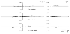
次に、本発明のように、防振群が絞り近傍にない場合のマクロレンズの防振時の収差変動の抑制について、摸式図を用いて説明する。 Next, suppression of aberration fluctuations at the time of image stabilization of the macro lens when the image stabilization group is not in the vicinity of the stop as in the present invention will be described using a schematic diagram.
一般に、光線の通過位置が光軸から離れるほど光線の偏角が大きくなる。すなわち単色収差の発生が大きくなるといえる。 In general, the deviation angle of a light beam increases as the passing position of the light beam moves away from the optical axis. That is, it can be said that the occurrence of monochromatic aberration increases.
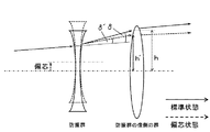
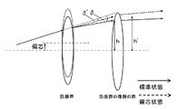
防振群に入射する任意の光線を考えたとき、標準状態の防振群入射前後の光線の偏角をδ、防振状態の防振群入射前後の光線の偏角をδ’、標準状態の防振群から射出される光線が防振群の像側の群に入射する位置とレンズ系全体の光軸との距離をh、防振状態の防振群から射出される光線が防振群の像側の群に入射する位置とレンズ系全体の光軸との距離をh’とする。 When considering an arbitrary ray incident on the image stabilization group, the declination of the beam before and after incidence of the anti-vibration group in the standard state is δ, the declination of the beam before and after incidence of the anti-vibration group in the anti-vibration state is δ ′, and the standard state The distance between the position where the light beam emitted from the image stabilization group enters the image side group of the image stabilization group and the optical axis of the entire lens system is h, and the light beam emitted from the image stabilization group in the image stabilization state is image stabilization. The distance between the position incident on the group on the image side of the group and the optical axis of the entire lens system is h ′.
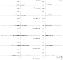
まず、図61を用いて、防振群の屈折力が負である場合を考える。 First, consider the case where the refractive power of the image stabilizing group is negative with reference to FIG.
図61は、防振群の屈折力が負である場合、標準状態と防振状態における、防振群に入射する光線の防振群入射前後の光線の偏角と、標準状態と防振状態における、防振群から射出される光線の、防振群の像側の群に入射する位置からレンズ系全体の光軸との距離とを表した図である。図からわかる通り、標準状態の偏角δに比べ、防振状態のとき、防振群の中心軸が光線の入射位置に近づく方向にシフトした場合、偏角δ’の絶対値は小さくなり、防振群の発生させる収差の絶対値は小さくなる傾向にある。この時、防振群の屈折力が負であることからh’は小さくなり、防振群より像側のレンズの発生させる収差の絶対値も小さくなる傾向にある。 FIG. 61 is a diagram illustrating the deflection angle of the light beam before and after entering the image stabilization group in the standard state and the image stabilization state, the standard state and the image stabilization state when the refractive power of the image stabilization group is negative. FIG. 6 is a diagram showing the distance of the light beam emitted from the image stabilization group to the optical axis of the entire lens system from the position incident on the image side group of the image stabilization group. As can be seen from the figure, when the central axis of the anti-vibration group is shifted in the direction approaching the incident position of the light beam in the anti-vibration state, the absolute value of the declination δ ′ is smaller than that in the standard state. The absolute value of the aberration generated by the anti-vibration group tends to be small. At this time, since the refractive power of the image stabilizing group is negative, h 'decreases, and the absolute value of the aberration generated by the lens on the image side from the image stabilizing group tends to decrease.
防振群と防振群より像側の群の発生させる収差の絶対値がともに小さくなるので、防振状態の収差変動を抑制するためには防振群と防振群より像側の群の発生させる収差は異符号であると良い。このため、防振群と防振群より像側の群の屈折力は異符号である方が良い。したがって、防振群の屈折力が負である場合は防振群より像側の群の屈折力は正であると良い。 Since the absolute value of the aberration generated by the image side group is smaller than the image stabilization group and the image stabilization group, in order to suppress aberration fluctuations in the image stabilization state, The aberrations to be generated are preferably different signs. For this reason, it is better that the refractive powers of the image stabilizing group and the image side group are different from each other. Therefore, when the refractive power of the image stabilizing group is negative, it is preferable that the image side group has a positive refractive power.
一方、図62を用いて、防振群の屈折力が正である場合を考える。 On the other hand, a case where the refractive power of the image stabilizing group is positive will be considered with reference to FIG.
図62は、防振群の屈折力が正である場合、標準状態と防振状態における、防振群に入射する光線の防振群入射前後の光線の偏角と、標準状態と防振状態における、防振群から射出される光線の、防振群の像側の群に入射する位置からレンズ系全体の光軸との距離とを表した図である。図から分かる通り、標準状態の偏角δに比べ、防振状態のとき、防振群の中心軸が光線の入射位置に近づく方向にシフトした場合、偏角δ’の絶対値は小さくなり、防振群の発生させる収差の絶対値は小さくなる傾向にある。この時、防振群の屈折力が正であることからh’は大きくなり、防振群より像側のレンズの発生させる収差の絶対値も大きくなる傾向にある。 FIG. 62 shows the deflection angle of light rays before and after entering the image stabilization group in the standard state and the image stabilization state, the standard state and the image stabilization state when the refractive power of the image stabilization group is positive. FIG. 6 is a diagram showing the distance of the light beam emitted from the image stabilization group to the optical axis of the entire lens system from the position incident on the image side group of the image stabilization group. As can be seen from the figure, when the central axis of the anti-vibration group is shifted in the direction approaching the incident position of the light beam in the anti-vibration state, the absolute value of the declination δ ′ is smaller than that in the standard state. The absolute value of the aberration generated by the anti-vibration group tends to be small. At this time, since the refractive power of the image stabilizing group is positive, h ′ increases, and the absolute value of the aberration generated by the lens on the image side tends to increase from the image stabilizing group.
防振群の発生させる収差の絶対値は小さく、防振群より像側の群の発生させる収差の絶対値は大きくなるので、防振状態の収差変動を抑制するためには防振群と防振群より像側の群の発生させる収差は同符号であると良い。このため、防振群と防振群より像側の群の屈折力は同符号である方が良い。したがって、防振群の屈折力が正である場合は防振群より像側の群の屈折力は正であると良い。 The absolute value of the aberration generated by the image stabilization group is small, and the absolute value of the aberration generated by the image side group is larger than that of the image stabilization group. The aberrations generated by the group on the image side with respect to the tremor group should have the same sign. For this reason, it is better that the refractive powers of the image stabilizing group and the image side group than the image stabilizing group have the same sign. Therefore, when the refractive power of the image stabilizing group is positive, it is preferable that the image side group has a positive refractive power.
これらのことから防振群が絞りの近傍にない場合において、防振群の屈折力の符号に関わらず、防振群より像側に正の屈折力の群を配置することによって防振時の収差変動を抑制することが出来る。 From these facts, when the anti-vibration group is not in the vicinity of the stop, regardless of the sign of the refractive power of the anti-vibration group, by arranging a group of positive refractive power on the image side from the anti-vibration group Aberration variation can be suppressed.
本発明のマクロレンズは負の屈折力の第3レンズ群L3を、物体側から順に負の屈折力のL3aレンズ成分L3aと正の屈折力のL3bレンズ成分L3bに分割して、L3aレンズ成分L3aを防振群としている。 The macro lens of the present invention divides the third lens unit L3 having a negative refractive power into an L3a lens component L3a having a negative refractive power and an L3b lens component L3b having a positive refractive power in order from the object side, thereby obtaining an L3a lens component L3a. Is the anti-vibration group.
一般に、防振群の移動に対する像面の移動量は、以下の式(a)で示される。 In general, the amount of movement of the image plane with respect to the movement of the image stabilizing group is expressed by the following equation (a).
(a)Kos=Δy/Δx=(1−βos)・βrear
ただし、
Kos:防振係数
Δy:像面の光軸へ直交する方向への移動量
Δx:防振群の光軸へ直交する方向への移動量
βos:防振群の結像倍率
βrear:防振群より像側のレンズ群の結像倍率
(A) Kos = Δy / Δx = (1−βos) · βrear
However,
Kos: anti-vibration coefficient Δy: movement amount in the direction orthogonal to the optical axis of the image plane Δx: movement amount in the direction orthogonal to the optical axis of the anti-vibration group βos: imaging magnification of the anti-vibration group βreal: anti-vibration group Image magnification of the lens group on the image side
式(a)に示されるKosの値があまりに小さくなると、必要とされる像の光軸直交方向への移動量を得るための防振群の移動量を大きくしなければならず、鏡筒の外径を大きくする必要が有り、または像の光軸直交方向への移動量を十分に確保できないために防振の制御に支障を生じ、防振効果が低下してしまう。 If the value of Kos shown in the equation (a) is too small, the movement amount of the image stabilizing group for obtaining the required movement amount of the image in the direction orthogonal to the optical axis must be increased. It is necessary to increase the outer diameter, or the amount of movement of the image in the direction orthogonal to the optical axis cannot be ensured, resulting in a problem in controlling the image stabilization and reducing the image stabilization effect.
また、フォーカシング時に移動するレンズ群に防振のための機構を搭載すると、機構が複雑化して鏡筒径の増大を招き、また、フォーカス群の重量増加を招いてフォーカシング速度が低下するなどの問題がある。したがって、防振群としてはフォーカシング時に像面に対して固定であることが望ましい。 In addition, if a lens unit that moves during focusing is equipped with a vibration-proof mechanism, the mechanism becomes complicated, leading to an increase in the lens barrel diameter, and an increase in the weight of the focus group, resulting in a decrease in focusing speed. There is. Therefore, it is desirable that the image stabilizing group is fixed with respect to the image plane during focusing.
先に述べたように、第1レンズ群L1やL2aレンズ成分L2aは収差の製造誤差感度が大きくなりがちであるので、光軸に対して直交する方向に移動させた際の収差変動が大きいため防振群に適さない。 As described above, since the first lens unit L1 and the L2a lens component L2a tend to have high aberration manufacturing error sensitivity, the aberration variation when moved in the direction orthogonal to the optical axis is large. Not suitable for anti-vibration group.
L2b成分L2bのKosを大きくするためにはL2bレンズ成分L2bの屈折力を大きくする必要があるが、この時L2bレンズ成分L2bまでの合成系の屈折力が強くなってL2cレンズ成分L2cの屈折力が弱くなるので、L2cレンズ成分L2cのフォーカシング時の移動量が増大してしまい、マクロレンズの全長の抑制が難しくなる。このためにL2bレンズ成分L2bは屈折力を大きくしづらいためにKosの値を大きく出来ず、やはり防振群に適さない。 In order to increase the Kos of the L2b component L2b, it is necessary to increase the refractive power of the L2b lens component L2b. At this time, the refractive power of the combined system up to the L2b lens component L2b increases and the refractive power of the L2c lens component L2c increases. Is weakened, the amount of movement of the L2c lens component L2c during focusing increases, making it difficult to suppress the overall length of the macro lens. For this reason, the L2b lens component L2b is difficult to increase the refractive power, so the value of Kos cannot be increased, and is not suitable for the vibration proof group.
L2cレンズ成分L2cはフォーカシング時に像面に対して位置が固定されていないため、防振群には好ましくない。 Since the position of the L2c lens component L2c is not fixed with respect to the image plane during focusing, it is not preferable for the image stabilizing group.
以上より、第3レンズ群L3の一部に防振群を設けることが望ましい。 From the above, it is desirable to provide a vibration proof group in a part of the third lens group L3.
更に、レンズ系の全長を短縮するためには第3レンズ群L3が全体として負の屈折力であることが望まれる。更に、前述のように防振時の収差変動を抑制するためには防振群より像側に正の屈折力のレンズ群を持つことが望まれる。 Further, in order to shorten the overall length of the lens system, it is desirable that the third lens unit L3 has a negative refractive power as a whole. Further, as described above, in order to suppress aberration fluctuations during image stabilization, it is desirable to have a lens unit having a positive refractive power on the image side from the image stabilization group.
以上の理由より、負の屈折力の第3レンズ群L3を物体側から順に負の屈折力のL3aレンズ成分L3aと正の屈折力のL3bレンズ成分L3bに分割し、L3aレンズ成分L3aで防振を行うことが非常に望ましい。 For the above reasons, the third lens unit L3 having negative refractive power is divided into an L3a lens component L3a having negative refractive power and an L3b lens component L3b having positive refractive power in order from the object side, and the vibration is prevented by the L3a lens component L3a. It is highly desirable to do.
更に、偏芯時の横色収差の変動を抑えるためにはL3aレンズ成分L3aに少なくとも1枚の正レンズと1枚の負レンズを含み、色収差の補正を行うことが好ましい。 Further, in order to suppress the variation of lateral chromatic aberration at the time of decentering, it is preferable to include at least one positive lens and one negative lens in the L3a lens component L3a to correct chromatic aberration.
更に、本発明のマクロレンズでは、以下の条件を満足することが望ましい。
(2)0.35<|fL3a/fL3b|<0.47
ただし、
fL3a:L3aレンズ成分L3aの焦点距離
fL3b:L3bレンズ成分L3bの焦点距離
f:レンズ系全体の無限遠合焦状態における合成焦点距離
Furthermore, it is desirable for the macro lens of the present invention to satisfy the following conditions.
(2) 0.35 <| fL3a / fL3b | <0.47
However,
fL3a: Focal length of L3a lens component L3a fL3b: Focal length of L3b lens component L3b f: Composite focal length in the infinitely focused state of the entire lens system
条件式(2)はL3aレンズ成分L3aとL3bレンズ成分L3bの焦点距離の比を規定し、鏡筒の小型化と防振時の収差変動の抑制に関して好ましい範囲を示す。 Conditional expression (2) defines the ratio of the focal lengths of the L3a lens component L3a and the L3b lens component L3b, and indicates a preferable range in terms of downsizing the lens barrel and suppressing aberration fluctuations during image stabilization.
条件式(2)の上限を上回ってL3aレンズ成分L3aの屈折力がL3bレンズ成分L3bに対して弱くなりすぎると、第3レンズ群L3全体の屈折力が弱くなってレンズ系の全長の大型化を招き、また防振時のL3aレンズ成分L3aの移動量が増大して鏡筒全体の大型化を招く。 If the refractive power of the L3a lens component L3a exceeds the upper limit of the conditional expression (2) and becomes too weak with respect to the L3b lens component L3b, the refractive power of the entire third lens unit L3 becomes weak and the overall length of the lens system increases. In addition, the amount of movement of the L3a lens component L3a at the time of image stabilization increases, leading to an increase in the size of the entire lens barrel.
一方、条件式(2)の下限を下回ってL3aレンズ成分L3aの屈折力がL3bレンズ成分L3bに対して強くなりすぎると、防振時の収差変動を抑制することが難しくなる。 On the other hand, if the refractive power of the L3a lens component L3a is too strong with respect to the L3b lens component L3b below the lower limit of the conditional expression (2), it is difficult to suppress aberration fluctuations during image stabilization.
次いで、軸上色収差の補正について述べる。 Next, correction of axial chromatic aberration will be described.
前述のように入射瞳をより物体側に近づけるためにはL2aレンズ成分L2aとL2bレンズ成分L2bの屈折力を強くすると良いが、特にパワーの強いL2aレンズ成分L2aにおいて凹レンズの発生させる色収差が大きくなり、レンズ系全体としては軸上色収差が補正過剰の状態となってしまう。近距離側ではレンズ系全体の軸上色収差が拡大されてしまうため、特に近距離側の性能が低下する問題を生じる。 As described above, in order to bring the entrance pupil closer to the object side, it is preferable to increase the refractive power of the L2a lens component L2a and the L2b lens component L2b. However, the chromatic aberration generated by the concave lens is particularly large in the L2a lens component L2a having high power. In the entire lens system, axial chromatic aberration is overcorrected. On the short distance side, the axial chromatic aberration of the entire lens system is enlarged, and this causes a problem that the performance on the short distance side is deteriorated.
そこで、上記問題を解決するため、L2bレンズ成分L2bの凸レンズの分散を大きく設定することで、L2aレンズ成分L2aの凹レンズが発生させる色収差を打ち消し、レンズ系全体の軸上色収差を良好に補正することができる。 Therefore, in order to solve the above problem, by setting the dispersion of the convex lens of the L2b lens component L2b to be large, the chromatic aberration generated by the concave lens of the L2a lens component L2a can be canceled and the axial chromatic aberration of the entire lens system can be corrected well. Can do.
更に、本発明のマクロレンズでは、以下の条件を満足することが望ましい。
(3)22.0<νdL2b<36.0
ただし
νdL2b:L2bレンズ成分L2bを構成する凸レンズの硝材のd線基準のアッベ数の最小値
Furthermore, it is desirable for the macro lens of the present invention to satisfy the following conditions.
(3) 22.0 <νdL2b <36.0
However, νdL2b: the minimum value of the Abbe number on the d-line basis of the glass material of the convex lens constituting the L2b lens component L2b
条件式(3)はL2bレンズ成分L2bを構成する凸レンズの硝材のアッベ数の最小値を規定し、軸上色収差補正に関する好ましい範囲を示す。 Conditional expression (3) defines the minimum value of the Abbe number of the glass material of the convex lens constituting the L2b lens component L2b, and indicates a preferable range relating to axial chromatic aberration correction.
条件式(3)の上限を上回ってL2bレンズ成分L2bを構成する凸レンズの硝材のアッベ数の最小値が大きくなると、L2aレンズ成分L2aの凸レンズの発生させる色収差を補正することが難しくなる。 If the minimum value of the Abbe number of the glass material of the convex lens constituting the L2b lens component L2b exceeds the upper limit of the conditional expression (3), it becomes difficult to correct chromatic aberration generated by the convex lens of the L2a lens component L2a.
条件式(3)の下限を下回ってL2bレンズ成分L2bを構成する凸レンズの硝材のアッベ数の最小値が小さくなると、硝材の透過率が悪い傾向にあるため、好ましくない。 If the minimum value of the Abbe number of the glass material of the convex lens constituting the L2b lens component L2b is below the lower limit of the conditional expression (3), the transmittance of the glass material tends to be bad, which is not preferable.
更に、L2bレンズ成分L2bが1枚の正レンズからなることによって構成枚数の削減による低コスト化や、全長の短縮などに有効である。 Furthermore, since the L2b lens component L2b is composed of a single positive lens, it is effective in reducing the cost by reducing the number of constituent elements, shortening the overall length, and the like.
防振時の像面湾曲の変動を小さく抑えるためにはL3bレンズ成分L3bで正のペッツバール和の絶対値を大きくし、防振群であるL3aレンズ成分L3aのペッツバール和を打ち消すことが有効である。 In order to suppress the fluctuation of the curvature of field at the time of image stabilization, it is effective to increase the absolute value of the positive Petzval sum with the L3b lens component L3b and cancel the Petzval sum of the L3a lens component L3a that is the image stabilization group. .
そこで、L3bレンズ成分L3bを少なくとも2枚の正レンズと少なくとも1枚の負レンズにて構成することで、コマ収差や倍率色収差の悪化を避けながらペッツバール和の絶対値を大きくすることが容易となる。 Therefore, by configuring the L3b lens component L3b with at least two positive lenses and at least one negative lens, it becomes easy to increase the absolute value of the Petzval sum while avoiding deterioration of coma and lateral chromatic aberration. .
そのためには条件式(4)および(5)を満足することが望ましい。
(4)0.85<ndL3bpl/ndL3bnh<0.97
(5)20<νdL3bpl−νdL3bnh
ただし、
ndL3bpl:L3bレンズ成分L3b中の正レンズの屈折率の最小値
ndL3bnh:L3bレンズ成分L3b中の負レンズの屈折率の最大値
νdL3bpl:L3bレンズ成分L3b中の正レンズのアッベ数の最小値
νdL3bnh:L3bレンズ成分L3b中の負レンズのアッベ数の最大値
For that purpose, it is desirable to satisfy conditional expressions (4) and (5).
(4) 0.85 <ndL3bpl / ndL3bnh <0.97
(5) 20 <νdL3bpl−νdL3bnh
However,
ndL3bpl: minimum value of refractive index of positive lens in L3b lens component L3b ndL3bnh: maximum value of refractive index of negative lens in L3b lens component L3b νdL3bpl: minimum value of Abbe number of positive lens in L3b lens component L3b νdL3bnh: Maximum Abbe number of negative lens in L3b lens component L3b
条件式(4)はL3bレンズ成分L3b内の正レンズと負レンズの硝材屈折率に関し、防振時の像面の変動を抑制するために望ましい範囲を示す。 Conditional expression (4) relates to the refractive index of the glass material of the positive lens and the negative lens in the L3b lens component L3b, and indicates a desirable range in order to suppress fluctuations in the image plane during image stabilization.
条件式(4)の上限を上回ってL3bレンズ成分L3bの凸レンズの硝材の屈折率が高くなると、L3bレンズ成分L3bのペッツバール和が小さくなって防振時の像面の変動を抑制することが難しくなる。 If the refractive index of the glass material of the convex lens of the L3b lens component L3b is higher than the upper limit of the conditional expression (4), the Petzval sum of the L3b lens component L3b becomes small, and it is difficult to suppress fluctuations in the image plane during image stabilization. Become.
条件式(4)の下限を下回ってL3bレンズ成分L3bの凸レンズの硝材の屈折率が低くなると、L3bレンズ成分L3bの凸レンズのrがきつくなってコマ収差の発生が大きくなりすぎ、防振状態の性能も低下してしまう。 If the refractive index of the glass material of the convex lens of the L3b lens component L3b becomes lower than the lower limit of the conditional expression (4), r of the convex lens of the L3b lens component L3b becomes too tight and the occurrence of coma becomes too large, resulting in a vibration-proof state. Performance will also decline.
条件式(5)はL3bレンズ成分L3b内の正レンズと負レンズの硝材のアッベ数に関し、防振時の横色収差の変動を抑制するために好ましい条件を示す。 Conditional expression (5) relates to the Abbe number of the glass material of the positive lens and the negative lens in the L3b lens component L3b, and shows a preferable condition for suppressing the variation of lateral chromatic aberration during the image stabilization.
条件式(5)の下限を下回って、L3bレンズ成分L3b内の正レンズと負レンズの硝材のアッベ数の差が少なくなるとL3bレンズ成分L3b内での色収差の補正が不完全となり、防振時の横色収差の変動が大きくなってしまう。 If the difference in the Abbe number between the positive lens and the negative lens in the L3b lens component L3b decreases below the lower limit of the conditional expression (5), the correction of chromatic aberration in the L3b lens component L3b becomes incomplete, and the vibration is prevented. Variation in lateral chromatic aberration will increase.
以下に、本発明のマクロレンズの数値実施例を説明する。 Hereinafter, numerical examples of the macro lens of the present invention will be described.
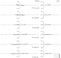
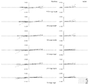
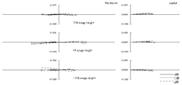
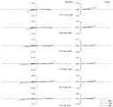
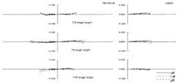
fは焦点距離、FnoはFナンバー、2ωは対角線画角を示す。番号はレンズの面番号を示し、rは各面の曲率半径、dは面間隔、ndはd線に対する屈折率、νdはd線基準のアッベ数を示す。 f indicates a focal length, Fno indicates an F number, and 2ω indicates a diagonal angle of view. The number indicates the surface number of the lens, r indicates the radius of curvature of each surface, d indicates the surface spacing, nd indicates the refractive index with respect to the d line, and νd indicates the Abbe number with respect to the d line.
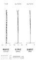
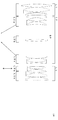
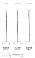
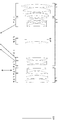
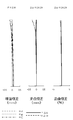
図1は、本発明の実施例1に係るマクロレンズの構成を示す図である。この図1のマクロレンズは、物体側から順に、フォーカシング時に像面に対して固定の正の屈折力の第1レンズ群L1と、フォーカシング時に像面に対して移動するレンズ群を含む第2レンズ群L2と、フォーカシング時に像面に対して固定の負の屈折力の第3レンズ群L3とから構成されている。第1レンズ群L1は物体側から順に、両凸レンズ、両凸レンズと両凹レンズの接合レンズ、物体側に凸面を向けた凸メニスカスレンズから構成されている。第2レンズ群L2は、物体側から順に、フォーカシング時に移動する負の屈折力のL2aレンズ成分L2aと、開口絞りを備えてフォーカシング時に像面に対して固定の正の屈折力のL2bレンズ成分L2bと、フォーカシング時に移動する正の屈折力のL2cレンズ成分L2cから構成されている。L2aレンズ成分L2aは両凹レンズ、物体側に凸面を向けた凹メニスカスレンズ、両凹レンズと物体側に凸面を向けた凸メニスカスレンズの接合レンズから構成されている。L2bレンズ成分L2bは開口絞りSPと両凸レンズで構成されている。L2c成分L2cは両凸レンズ、両凸レンズと両凹レンズの接合レンズで構成されている。第3レンズ群L3は、光軸と直交方向に移動することによって像ブレの補正を行う負の屈折力のL3aレンズ成分L3aと、正の屈折力のL3bレンズ成分L3bとから構成されている。L3aレンズ成分L3aは像側に凸面を向けた凸メニスカスレンズと両凹レンズの接合レンズで構成されている。L3bレンズ成分L3bは両凹レンズと両凸レンズの接合レンズ、両凸レンズから構成されている。 FIG. 1 is a diagram showing a configuration of a macro lens according to Example 1 of the present invention. The macro lens in FIG. 1 includes, in order from the object side, a first lens unit L1 having a positive refractive power that is fixed with respect to the image plane during focusing, and a second lens unit that includes a lens group that moves relative to the image plane during focusing. The lens unit L2 includes a third lens unit L3 having a negative refractive power that is fixed with respect to the image plane during focusing. The first lens unit L1 includes, in order from the object side, a biconvex lens, a cemented lens of a biconvex lens and a biconcave lens, and a convex meniscus lens having a convex surface facing the object side. The second lens unit L2 includes, in order from the object side, a negative refractive power L2a lens component L2a that moves during focusing, and a positive refractive power L2b lens component L2b that includes an aperture stop and is fixed with respect to the image plane during focusing. And an L2c lens component L2c having a positive refractive power that moves during focusing. The L2a lens component L2a includes a biconcave lens, a concave meniscus lens having a convex surface facing the object side, and a cemented lens of a biconcave lens and a convex meniscus lens having a convex surface facing the object side. The L2b lens component L2b is composed of an aperture stop SP and a biconvex lens. The L2c component L2c is composed of a biconvex lens and a cemented lens of a biconvex lens and a biconcave lens. The third lens unit L3 includes an L3a lens component L3a having a negative refractive power that corrects image blur by moving in a direction orthogonal to the optical axis, and an L3b lens component L3b having a positive refractive power. The L3a lens component L3a is composed of a cemented lens of a convex meniscus lens having a convex surface facing the image side and a biconcave lens. The L3b lens component L3b includes a cemented lens of a biconcave lens and a biconvex lens, and a biconvex lens.
[レンズ諸元]
r d nd νd
[1] 102.6120 4.3674 1.77250 49.62
[2] -182.7090 0.1500
[3] 48.7257 6.1801 1.49700 81.61
[4] -107.8610 1.2000 1.80518 25.46
[5] 96.3373 0.1500
[6] 50.1746 2.9890 1.59282 68.62
[7] 146.9140 可変
[8] -434.7160 1.0000 1.51680 64.20
[9] 27.5822 2.5975
[10] 85.7260 1.0000 1.62004 36.30
[11] 40.3122 3.2999
[12] -91.6348 1.0000 1.51742 52.15
[13] 33.1436 3.7593 1.84666 23.78
[14] 138.7790 可変
[15] 開口絞り 3.0000
[16] 140.6340 2.4029 1.80610 33.27
[17] -374.6100 可変
[18] 144.0050 3.7037 1.80420 46.50
[19] -71.1001 0.1500
[20] 82.9160 5.2196 1.59282 68.62
[21] -41.3644 1.0000 1.72825 28.32
[22] 194.0700 可変
[23] -348.5270 3.1362 1.72825 28.32
[24] -43.8708 1.0000 1.72916 54.67
[25] 43.8708 6.0421
[26] -79.1744 1.2352 1.80610 33.27
[27] 60.9025 5.1732 1.58913 61.25
[28] -75.1942 0.1500
[29] 59.3668 5.2523 1.71300 53.94
[30] -541.9380 Bf
[全体諸元]
撮影倍率 INF 1:2 1:1
f 101.93 92.54 76.41
Fno 2.91 4.37 5.83
2ω 24.16 15.59 9.44
[可変間隔]
撮影倍率 INF 1:2 1:1
d7 2.5628 9.6805 17.0287
d14 17.1441 10.0264 2.6782
d17 22.1238 11.5023 1.7500
d22 5.6147 16.2362 25.9885
Bf 52.3867 52.3868 52.3870
[条件式対応値]
実施例1
条件式(1)|fL2a・fL2b/f2| 0.396
条件式(2)|fL3a/fL3b| 0.450
条件式(3)νdL2a 33.27
条件式(4)ndL3bpl/ndL3bnh 0.880
条件式(5)νdL3bpl−νdL3bnh 20.67
[Lens specifications]
r d nd νd
[1] 102.6120 4.3674 1.77250 49.62
[2] -182.7090 0.1500
[3] 48.7257 6.1801 1.49700 81.61
[4] -107.8610 1.2000 1.80518 25.46
[5] 96.3373 0.1500
[6] 50.1746 2.9890 1.59282 68.62
[7] 146.9140 Variable
[8] -434.7160 1.0000 1.51680 64.20
[9] 27.5822 2.5975
[10] 85.7260 1.0000 1.62004 36.30
[11] 40.3122 3.2999
[12] -91.6348 1.0000 1.51742 52.15
[13] 33.1436 3.7593 1.84666 23.78
[14] 138.7790 Variable
[15] Aperture stop 3.0000
[16] 140.6340 2.4029 1.80610 33.27
[17] -374.6100 Variable
[18] 144.0050 3.7037 1.80420 46.50
[19] -71.1001 0.1500
[20] 82.9160 5.2196 1.59282 68.62
[21] -41.3644 1.0000 1.72825 28.32
[22] 194.0700 Variable
[23] -348.5270 3.1362 1.72825 28.32
[24] -43.8708 1.0000 1.72916 54.67
[25] 43.8708 6.0421
[26] -79.1744 1.2352 1.80610 33.27
[27] 60.9025 5.1732 1.58913 61.25
[28] -75.1942 0.1500
[29] 59.3668 5.2523 1.71300 53.94
[30] -541.9380 Bf
[Overall specifications]
Magnification INF 1: 2 1: 1
f 101.93 92.54 76.41
Fno 2.91 4.37 5.83
2ω 24.16 15.59 9.44
[Variable interval]
Magnification INF 1: 2 1: 1
d7 2.5628 9.6805 17.0287
d14 17.1441 10.0264 2.6782
d17 22.1238 11.5023 1.7500
d22 5.6147 16.2362 25.9885
Bf 52.3867 52.3868 52.3870
[Conditional expression values]
Example 1
Conditional expression (1) | fL2a · fL2b / f 2 | 0.396
Conditional expression (2) | fL3a / fL3b | 0.450
Conditional expression (3) νdL2a 33.27
Conditional expression (4) ndL3bpl / ndL3bnh 0.880
Conditional expression (5) νdL3bpl-νdL3bnh 20.67
図11は、本発明の実施例2に係るマクロレンズの構成を示す図である。この図11のマクロレンズは、物体側から順に、フォーカシング時に像面に対して固定の正の屈折力の第1レンズ群L1と、フォーカシング時に像面に対して移動するレンズ群を含む第2レンズ群L2と、フォーカシング時に像面に対して固定の負の屈折力の第3レンズ群L3とから構成される。第1レンズ群L1は物体側から順に、両凸レンズ、両凸レンズと両凹レンズの接合レンズ、物体側に凸面を向けた凸メニスカスレンズから構成されている。第2レンズ群L2は、物体側から順に、フォーカシング時に移動する負の屈折力のL2aレンズ成分L2aと、開口絞りを備えてフォーカシング時に像面に対して固定の正の屈折力のL2bレンズ成分L2bと、フォーカシング時に移動する正の屈折力のL2cレンズ成分L2cから構成されている。L2aレンズ成分L2aは両凹レンズ、両凹レンズと物体側に凸面を向けた凸メニスカスレンズの接合レンズから構成されている。L2bレンズ成分L2bは開口絞りSPと両凸レンズで構成されている。L2c成分L2cは両凸レンズ、両凸レンズと両凹レンズの接合レンズで構成されている。第3レンズ群L3は、光軸と直交方向に移動することによって像ブレの補正を行う負の屈折力のL3aレンズ成分L3aと、正の屈折力のL3bレンズ成分L3bとから構成されている。L3aレンズ成分L3aは両凸レンズと両凹レンズの接合レンズで構成されている。L3bレンズ成分L3bは両凹レンズと両凸レンズの接合レンズ、物体側に凸面を向けた凸メニスカスレンズから構成されている。 FIG. 11 is a diagram showing a configuration of a macro lens according to Example 2 of the present invention. The macro lens in FIG. 11 includes, in order from the object side, a first lens unit L1 having a positive refractive power that is fixed with respect to the image plane during focusing, and a second lens unit that includes a lens group that moves with respect to the image plane during focusing. The lens unit L2 includes a third lens unit L3 having a negative refractive power that is fixed with respect to the image plane during focusing. The first lens unit L1 includes, in order from the object side, a biconvex lens, a cemented lens of a biconvex lens and a biconcave lens, and a convex meniscus lens having a convex surface facing the object side. The second lens unit L2 includes, in order from the object side, a negative refractive power L2a lens component L2a that moves during focusing, and a positive refractive power L2b lens component L2b that includes an aperture stop and is fixed with respect to the image plane during focusing. And an L2c lens component L2c having a positive refractive power that moves during focusing. The L2a lens component L2a is composed of a biconcave lens, a cemented lens of a biconcave lens and a convex meniscus lens having a convex surface facing the object side. The L2b lens component L2b is composed of an aperture stop SP and a biconvex lens. The L2c component L2c is composed of a biconvex lens and a cemented lens of a biconvex lens and a biconcave lens. The third lens unit L3 includes an L3a lens component L3a having a negative refractive power that corrects image blur by moving in a direction orthogonal to the optical axis, and an L3b lens component L3b having a positive refractive power. The L3a lens component L3a is composed of a cemented lens of a biconvex lens and a biconcave lens. The L3b lens component L3b includes a cemented lens of a biconcave lens and a biconvex lens, and a convex meniscus lens having a convex surface facing the object side.
[レンズ諸元]
r d nd νd
[1] 185.7260 4.1345 1.80420 46.50
[2] -142.8660 0.1500
[3] 57.2079 7.2742 1.49700 81.61
[4] -74.3703 1.2000 1.72825 28.32
[5] 97.1863 0.1500
[6] 45.6388 3.5038 1.59282 68.62
[7] 174.3410 可変
[8] -751.5470 1.0000 1.58144 40.89
[9] 27.7373 4.6366
[10] -102.9860 1.0000 1.58913 61.25
[11] 29.0817 4.1439 1.84666 23.78
[12] 95.6623 可変
[13] 開口絞り 2.5000
[14] 212.6700 3.9000 1.74950 35.04
[15] -212.6700 可変
[16] 285.7990 3.1893 1.83481 42.72
[17] -78.5339 0.1500
[18] 79.8253 5.4121 1.72916 54.67
[19] -41.3502 1.0000 1.78472 25.72
[20] 246.5610 可変
[21] 516.8770 3.8838 1.75520 27.53
[22] -39.4078 1.0000 1.77250 49.62
[23] 39.4078 6.4278
[24] -60.3091 1.2000 1.80610 33.27
[25] 60.3091 4.9674 1.72916 54.67
[26] -78.4018 0.1500
[27] 54.3427 4.6470 1.72916 54.67
[28] 359.3020 Bf
[全体諸元]
撮影倍率 INF 1:2 1:1
f 101.99 90.99 74.27
Fno 2.91 4.37 5.82
2ω 24.29 15.57 9.26
[可変間隔]
撮影倍率 INF 1:2 1:1
d7 2.9937 10.8578 19.2351
d12 20.4133 12.5492 4.1719
d15 21.3586 11.1841 1.7500
d20 4.7062 14.8807 24.3148
Bf 52.9078 52.9078 52.9078
[条件式対応値]
実施例2
条件式(1)|fL2a・fL2b/f2| 0.482
条件式(2)|fL3a/fL3b| 0.386
条件式(3)νdL2a 35.04
条件式(4)ndL3bpl/ndL3bnh 0.957
条件式(5)νdL3bpl−νdL3bnh 21.40
[Lens specifications]
r d nd νd
[1] 185.7260 4.1345 1.80420 46.50
[2] -142.8660 0.1500
[3] 57.2079 7.2742 1.49700 81.61
[4] -74.3703 1.2000 1.72825 28.32
[5] 97.1863 0.1500
[6] 45.6388 3.5038 1.59282 68.62
[7] 174.3410 Variable
[8] -751.5470 1.0000 1.58144 40.89
[9] 27.7373 4.6366
[10] -102.9860 1.0000 1.58913 61.25
[11] 29.0817 4.1439 1.84666 23.78
[12] 95.6623 Variable
[13] Aperture stop 2.5000
[14] 212.6700 3.9000 1.74950 35.04
[15] -212.6700 variable
[16] 285.7990 3.1893 1.83481 42.72
[17] -78.5339 0.1500
[18] 79.8253 5.4121 1.72916 54.67
[19] -41.3502 1.0000 1.78472 25.72
[20] 246.5610 Variable
[21] 516.8770 3.8838 1.75520 27.53
[22] -39.4078 1.0000 1.77250 49.62
[23] 39.4078 6.4278
[24] -60.3091 1.2000 1.80610 33.27
[25] 60.3091 4.9674 1.72916 54.67
[26] -78.4018 0.1500
[27] 54.3427 4.6470 1.72916 54.67
[28] 359.3020 Bf
[Overall specifications]
Magnification INF 1: 2 1: 1
f 101.99 90.99 74.27
Fno 2.91 4.37 5.82
2ω 24.29 15.57 9.26
[Variable interval]
Magnification INF 1: 2 1: 1
d7 2.9937 10.8578 19.2351
d12 20.4133 12.5492 4.1719
d15 21.3586 11.1841 1.7500
d20 4.7062 14.8807 24.3148
Bf 52.9078 52.9078 52.9078
[Conditional expression values]
Example 2
Conditional expression (1) | fL2a · fL2b / f 2 | 0.482
Conditional expression (2) | fL3a / fL3b | 0.386
Conditional expression (3) νdL2a 35.04
Conditional expression (4) ndL3bpl / ndL3bnh 0.957
Conditional expression (5) νdL3bpl-νdL3bnh 21.40
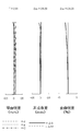
図21は、本発明の実施例3に係るマクロレンズの構成を示す図である。この図21のマクロレンズは、物体側から順に、フォーカシング時に像面に対して固定の正の屈折力の第1レンズ群L1と、フォーカシング時に像面に対して移動するレンズ群を含む第2レンズ群L2と、フォーカシング時に像面に対して固定の負の屈折力の第3レンズ群L3とから構成される。第1レンズ群L1は物体側から順に、両凸レンズ、両凸レンズと両凹レンズの接合レンズ、物体側に凸面を向けた凸メニスカスレンズから構成されている。第2レンズ群L2は、物体側から順に、フォーカシング時に移動する負の屈折力のL2aレンズ成分L2aと、開口絞りを備えてフォーカシング時に像面に対して固定の正の屈折力のL2bレンズ成分L2bと、フォーカシング時に移動する正の屈折力のL2cレンズ成分L2cから構成されている。L2aレンズ成分L2aは両凹レンズ、両凹レンズと物体側に凸面を向けた凸メニスカスレンズの接合レンズから構成されている。L2bレンズ成分L2bは開口絞りSPと両凸レンズで構成されている。L2c成分L2cは両凸レンズ、両凸レンズと両凹レンズの接合レンズで構成されている。第3レンズ群L3は、光軸と直交方向に移動することによって像ブレの補正を行う負の屈折力のL3aレンズ成分L3aと正の屈折力のL3bレンズ成分L3bとから構成されている。L3aレンズ成分L3aは像側に凸面を向けた凸メニスカスレンズと両凹レンズの接合レンズで構成されている。L3bレンズ成分L3bは両凹レンズと両凸レンズの接合レンズ、両凸レンズから構成されている。 FIG. 21 is a diagram showing a configuration of a macro lens according to Example 3 of the present invention. The macro lens of FIG. 21 includes, in order from the object side, a first lens unit L1 having a positive refractive power that is fixed with respect to the image plane during focusing, and a second lens unit that includes a lens group that moves with respect to the image plane during focusing. The lens unit L2 includes a third lens unit L3 having a negative refractive power that is fixed with respect to the image plane during focusing. The first lens unit L1 includes, in order from the object side, a biconvex lens, a cemented lens of a biconvex lens and a biconcave lens, and a convex meniscus lens having a convex surface facing the object side. The second lens unit L2 includes, in order from the object side, a negative refractive power L2a lens component L2a that moves during focusing, and a positive refractive power L2b lens component L2b that includes an aperture stop and is fixed with respect to the image plane during focusing. And an L2c lens component L2c having a positive refractive power that moves during focusing. The L2a lens component L2a is composed of a biconcave lens, a cemented lens of a biconcave lens and a convex meniscus lens having a convex surface facing the object side. The L2b lens component L2b is composed of an aperture stop SP and a biconvex lens. The L2c component L2c is composed of a biconvex lens and a cemented lens of a biconvex lens and a biconcave lens. The third lens unit L3 includes a negative refracting power L3a lens component L3a and a positive refracting power L3b lens component L3b that correct image blur by moving in the direction orthogonal to the optical axis. The L3a lens component L3a is composed of a cemented lens of a convex meniscus lens having a convex surface facing the image side and a biconcave lens. The L3b lens component L3b includes a cemented lens of a biconcave lens and a biconvex lens, and a biconvex lens.
[レンズ諸元]
r d nd νd
[1] 128.6080 4.5455 1.80420 46.50
[2] -167.8330 0.4707
[3] 60.4219 6.7522 1.49700 81.61
[4] -82.5691 1.2000 1.76182 26.61
[5] 107.5870 0.1500
[6] 49.5326 3.5410 1.59282 68.62
[7] 253.2330 可変
[8] -370.6000 0.9500 1.60342 38.01
[9] 26.3724 5.0209
[10] -83.0352 1.0000 1.51680 64.20
[11] 29.2567 4.0519 1.84666 23.78
[12] 90.1528 可変
[13] 開口絞り 2.3500
[14] 264.5900 2.8700 1.80518 25.46
[15] -170.7040 可変
[16] 597.3580 3.0967 1.80420 46.50
[17] -75.4415 0.1500
[18] 74.0520 5.8015 1.72916 54.67
[19] -38.7426 1.0000 1.76182 26.61
[20] 205.3230 可変
[21] -441.6700 3.4250 1.80518 25.46
[22] -41.1069 0.9500 1.77250 49.62
[23] 41.1069 4.3910
[24] -78.0813 1.2000 1.80610 33.27
[25] 43.4947 5.7207 1.72916 54.67
[26] -88.7465 0.1500
[27] 52.2983 4.7222 1.58913 61.25
[28] -1000.0000 Bf
[全体諸元]
撮影倍率 INF 1:2 1:1
f 101.89 91.82 75.55
Fno 2.91 4.38 5.83
2ω 24.05 15.30 8.97
[可変間隔]
撮影倍率 INF 1:2 1:1
d7 2.9446 10.5454 18.7377
d12 20.2254 12.6245 4.4322
d15 22.7309 12.5115 3.4024
d20 5.3898 15.6093 24.7184
Bf 53.3000 53.3000 53.3000
[条件式対応値]
実施例3
条件式(1)|fL2a・fL2b/f2| 0.418
条件式(2)|fL3a/fL3b| 0.447
条件式(3)νdL2a 25.46
条件式(4)ndL3bpl/ndL3bnh 0.880
条件式(5)νdL3bpl−νdL3bnh 21.40
[Lens specifications]
r d nd νd
[1] 128.6080 4.5455 1.80420 46.50
[2] -167.8330 0.4707
[3] 60.4219 6.7522 1.49700 81.61
[4] -82.5691 1.2000 1.76182 26.61
[5] 107.5870 0.1500
[6] 49.5326 3.5410 1.59282 68.62
[7] 253.2330 Variable
[8] -370.6000 0.9500 1.60342 38.01
[9] 26.3724 5.0209
[10] -83.0352 1.0000 1.51680 64.20
[11] 29.2567 4.0519 1.84666 23.78
[12] 90.1528 Variable
[13] Aperture stop 2.3500
[14] 264.5900 2.8700 1.80518 25.46
[15] -170.7040 Variable
[16] 597.3580 3.0967 1.80420 46.50
[17] -75.4415 0.1500
[18] 74.0520 5.8015 1.72916 54.67
[19] -38.7426 1.0000 1.76182 26.61
[20] 205.3230 Variable
[21] -441.6700 3.4250 1.80518 25.46
[22] -41.1069 0.9500 1.77250 49.62
[23] 41.1069 4.3910
[24] -78.0813 1.2000 1.80610 33.27
[25] 43.4947 5.7207 1.72916 54.67
[26] -88.7465 0.1500
[27] 52.2983 4.7222 1.58913 61.25
[28] -1000.0000 Bf
[Overall specifications]
Magnification INF 1: 2 1: 1
f 101.89 91.82 75.55
Fno 2.91 4.38 5.83
2ω 24.05 15.30 8.97
[Variable interval]
Magnification INF 1: 2 1: 1
d7 2.9446 10.5454 18.7377
d12 20.2254 12.6245 4.4322
d15 22.7309 12.5115 3.4024
d20 5.3898 15.6093 24.7184
Bf 53.3000 53.3000 53.3000
[Conditional expression values]
Example 3
Conditional expression (1) | fL2a · fL2b / f 2 | 0.418
Conditional expression (2) | fL3a / fL3b | 0.447
Conditional expression (3) νdL2a 25.46
Conditional expression (4) ndL3bpl / ndL3bnh 0.880
Conditional expression (5) νdL3bpl-νdL3bnh 21.40
図31は、本発明の実施例4に係るマクロレンズの構成を示す図である。この図31のマクロレンズは、物体側から順に、フォーカシング時に像面に対して固定の正の屈折力の第1レンズ群L1と、フォーカシング時に像面に対して移動するレンズ群を含む第2レンズ群L2と、フォーカシング時に像面に対して固定の負の屈折力の第3レンズ群L3とから構成される。第1レンズ群L1は物体側から順に、両凸レンズ、両凸レンズと両凹レンズの接合レンズ、物体側に凸面を向けた凸メニスカスレンズから構成されている。第2レンズ群L2は、物体側から順に、フォーカシング時に移動する負の屈折力のL2aレンズ成分L2aと、開口絞りを備えてフォーカシング時に像面に対して固定の正の屈折力のL2bレンズ成分L2bと、フォーカシング時に移動する正の屈折力のL2cレンズ成分L2cから構成されている。L2aレンズ成分L2aは両凹レンズ、両凹レンズと物体側に凸面を向けた凸メニスカスレンズの接合レンズから構成されている。L2bレンズ成分L2bは開口絞りSPと両凸レンズで構成されている。L2c成分L2cは両凸レンズ、両凸レンズと両凹レンズの接合レンズで構成されている。第3レンズ群L3は、光軸と直交方向に移動することによって像ブレの補正を行う負の屈折力のL3aレンズ成分L3aと正の屈折力のL3bレンズ成分L3bとから構成されている。L3aレンズ成分L3aは像側に凸面を向けた凸メニスカスレンズと両凹レンズの接合レンズで構成されている。L3bレンズ成分L3bは両凹レンズと両凸レンズの接合レンズ、両凸レンズから構成されている。 FIG. 31 is a diagram showing a configuration of a macro lens according to Example 4 of the present invention. The macro lens of FIG. 31 includes, in order from the object side, a first lens unit L1 having a positive refractive power that is fixed with respect to the image plane during focusing, and a second lens unit that includes a lens group that moves with respect to the image plane during focusing. The lens unit L2 includes a third lens unit L3 having a negative refractive power that is fixed with respect to the image plane during focusing. The first lens unit L1 includes, in order from the object side, a biconvex lens, a cemented lens of a biconvex lens and a biconcave lens, and a convex meniscus lens having a convex surface facing the object side. The second lens unit L2 includes, in order from the object side, a negative refractive power L2a lens component L2a that moves during focusing, and a positive refractive power L2b lens component L2b that includes an aperture stop and is fixed with respect to the image plane during focusing. And an L2c lens component L2c having a positive refractive power that moves during focusing. The L2a lens component L2a is composed of a biconcave lens, a cemented lens of a biconcave lens and a convex meniscus lens having a convex surface facing the object side. The L2b lens component L2b is composed of an aperture stop SP and a biconvex lens. The L2c component L2c is composed of a biconvex lens and a cemented lens of a biconvex lens and a biconcave lens. The third lens unit L3 includes a negative refracting power L3a lens component L3a and a positive refracting power L3b lens component L3b that correct image blur by moving in the direction orthogonal to the optical axis. The L3a lens component L3a is composed of a cemented lens of a convex meniscus lens having a convex surface facing the image side and a biconcave lens. The L3b lens component L3b includes a cemented lens of a biconcave lens and a biconvex lens, and a biconvex lens.
[レンズ諸元]
r d nd νd
[1] 129.0850 4.5536 1.80420 46.50
[2] -168.4560 0.7593
[3] 60.1581 6.7285 1.49700 81.61
[4] -82.4177 1.2000 1.76182 26.61
[5] 107.3900 0.1500
[6] 49.2292 3.5517 1.59282 68.62
[7] 260.5460 可変
[8] -359.5780 0.9500 1.60342 38.01
[9] 26.4941 4.9881
[10] -80.7403 1.0000 1.51680 64.20
[11] 29.3575 3.9702 1.84666 23.78
[12] 86.6184 可変
[13] 開口絞り 2.3500
[14] 249.8780 2.9386 1.80518 25.46
[15] -161.2120 可変
[16] 570.8840 3.0684 1.80420 46.50
[17] -76.7882 0.1500
[18] 75.4847 5.7703 1.72916 54.67
[19] -38.7023 1.0000 1.76182 26.61
[20] 218.3240 可変
[21] -399.5920 3.3872 1.80518 25.46
[22] -41.4772 0.9500 1.77250 49.62
[23] 41.4772 4.3666
[24] -78.7902 1.2000 1.80610 33.27
[25] 42.8746 5.6999 1.72916 54.67
[26] -93.6099 0.1500
[27] 53.7454 4.6951 1.58913 61.25
[28] -449.7860 Bf
[全体諸元]
撮影倍率 INF 1:2 1:1
f 101.71 91.84 75.68
Fno 2.91 4.38 5.83
2ω 24.09 15.33 8.93
[可変間隔]
撮影倍率 INF 1:2 1:1
d7 2.9138 10.4099 18.6188
d12 20.1047 12.6086 4.3997
d15 22.7964 12.4801 3.3614
d20 5.4077 15.7240 24.8427
Bf 53.3000 53.3001 53.3001
[条件式対応値]
実施例4
条件式(1)|fL2a・fL2b/f2| 0.388
条件式(2)|fL3a/fL3b| 0.448
条件式(3)νdL2a 25.46
条件式(4)ndL3bpl/ndL3bnh 0.880
条件式(5)νdL3bpl−νdL3bnh 21.40
[Lens specifications]
r d nd νd
[1] 129.0850 4.5536 1.80420 46.50
[2] -168.4560 0.7593
[3] 60.1581 6.7285 1.49700 81.61
[4] -82.4177 1.2000 1.76182 26.61
[5] 107.3900 0.1500
[6] 49.2292 3.5517 1.59282 68.62
[7] 260.5460 Variable
[8] -359.5780 0.9500 1.60342 38.01
[9] 26.4941 4.9881
[10] -80.7403 1.0000 1.51680 64.20
[11] 29.3575 3.9702 1.84666 23.78
[12] 86.6184 Variable
[13] Aperture stop 2.3500
[14] 249.8780 2.9386 1.80518 25.46
[15] -161.2120 variable
[16] 570.8840 3.0684 1.80420 46.50
[17] -76.7882 0.1500
[18] 75.4847 5.7703 1.72916 54.67
[19] -38.7023 1.0000 1.76182 26.61
[20] 218.3240 Variable
[21] -399.5920 3.3872 1.80518 25.46
[22] -41.4772 0.9500 1.77250 49.62
[23] 41.4772 4.3666
[24] -78.7902 1.2000 1.80610 33.27
[25] 42.8746 5.6999 1.72916 54.67
[26] -93.6099 0.1500
[27] 53.7454 4.6951 1.58913 61.25
[28] -449.7860 Bf
[Overall specifications]
Magnification INF 1: 2 1: 1
f 101.71 91.84 75.68
Fno 2.91 4.38 5.83
2ω 24.09 15.33 8.93
[Variable interval]
Magnification INF 1: 2 1: 1
d7 2.9138 10.4099 18.6188
d12 20.1047 12.6086 4.3997
d15 22.7964 12.4801 3.3614
d20 5.4077 15.7240 24.8427
Bf 53.3000 53.3001 53.3001
[Conditional expression values]
Example 4
Conditional expression (1) | fL2a · fL2b / f 2 | 0.388
Conditional expression (2) | fL3a / fL3b | 0.448
Conditional expression (3) νdL2a 25.46
Conditional expression (4) ndL3bpl / ndL3bnh 0.880
Conditional expression (5) νdL3bpl-νdL3bnh 21.40
図41は、本発明の実施例5に係るマクロレンズの構成を示す図である。この図41のマクロレンズは、物体側から順に、フォーカシング時に像面に対して固定の正の屈折力の第1レンズ群L1と、フォーカシング時に像面に対して移動するレンズ群を含む第2レンズ群L2と、フォーカシング時に像面に対して固定の負の屈折力の第3レンズ群L3とから構成される。第1レンズ群L1は物体側から順に、両凸レンズ、両凸レンズと両凹レンズの接合レンズ、物体側に凸面を向けた凸メニスカスレンズから構成されている。第2レンズ群L2は、物体側から順に、フォーカシング時に移動する負の屈折力のL2aレンズ成分L2aと、開口絞りを備えてフォーカシング時に像面に対して固定の正の屈折力のL2bレンズ成分L2bと、フォーカシング時に移動する正の屈折力のL2cレンズ成分L2cから構成されている。L2aレンズ成分L2aは両凹レンズ、両凹レンズと物体側に凸面を向けた凸メニスカスレンズの接合レンズから構成されている。L2bレンズ成分L2bは開口絞りSPと両凸レンズで構成されている。L2c成分L2cは両凸レンズ、両凸レンズと両凹レンズの接合レンズで構成されている。第3レンズ群L3は、光軸と直交方向に移動することによって像ブレの補正を行う負の屈折力のL3aレンズ成分L3aと正の屈折力のL3bレンズ成分L3bとから構成されている。L3aレンズ成分L3aは両凸レンズと両凹レンズの接合レンズで構成されている。L3bレンズ成分L3bは両凹レンズと両凸レンズの接合レンズ、物体側に凸面を向けた凸メニスカスレンズから構成されている。 FIG. 41 is a diagram showing a configuration of a macro lens according to Example 5 of the present invention. The macro lens of FIG. 41 includes, in order from the object side, a first lens unit L1 having a positive refractive power that is fixed with respect to the image plane during focusing, and a second lens unit that includes a lens group that moves with respect to the image plane during focusing. The lens unit L2 includes a third lens unit L3 having a negative refractive power that is fixed with respect to the image plane during focusing. The first lens unit L1 includes, in order from the object side, a biconvex lens, a cemented lens of a biconvex lens and a biconcave lens, and a convex meniscus lens having a convex surface facing the object side. The second lens unit L2 includes, in order from the object side, a negative refractive power L2a lens component L2a that moves during focusing, and a positive refractive power L2b lens component L2b that includes an aperture stop and is fixed with respect to the image plane during focusing. And an L2c lens component L2c having a positive refractive power that moves during focusing. The L2a lens component L2a is composed of a biconcave lens, a cemented lens of a biconcave lens and a convex meniscus lens having a convex surface facing the object side. The L2b lens component L2b is composed of an aperture stop SP and a biconvex lens. The L2c component L2c is composed of a biconvex lens and a cemented lens of a biconvex lens and a biconcave lens. The third lens unit L3 includes a negative refracting power L3a lens component L3a and a positive refracting power L3b lens component L3b that correct image blur by moving in the direction orthogonal to the optical axis. The L3a lens component L3a is composed of a cemented lens of a biconvex lens and a biconcave lens. The L3b lens component L3b includes a cemented lens of a biconcave lens and a biconvex lens, and a convex meniscus lens having a convex surface facing the object side.
[レンズ諸元]
r d nd νd
[1] 212.3680 4.0468 1.80420 46.50
[2] -133.1660 0.1500
[3] 56.4175 6.7613 1.49700 81.61
[4] -73.3427 1.2000 1.72825 28.32
[5] 95.3456 0.1500
[6] 45.8513 3.5399 1.59282 68.62
[7] 183.9620 可変
[8] -670.2770 1.0000 1.56883 56.04
[9] 27.9328 4.7188
[10] -100.9040 1.0000 1.51742 52.15
[11] 29.9789 3.7664 1.84666 23.78
[12] 73.1624 可変
[13] 開口絞り 3.0372
[14] 218.1310 3.0701 1.71736 29.50
[15] -218.1310 可変
[16] 275.1680 3.2373 1.83481 42.72
[17] -78.0390 0.1500
[18] 78.7692 5.4154 1.72916 54.67
[19] -42.3040 1.0000 1.78472 25.72
[20] 233.6270 可変
[21] 525.2540 3.8880 1.75520 27.53
[22] -39.7240 1.0000 1.77250 49.62
[23] 39.7240 5.2491
[24] -57.3847 1.2000 1.80610 33.27
[25] 57.3847 4.9510 1.72916 54.67
[26] -78.5120 0.1500
[27] 57.9260 3.6790 1.72916 54.67
[28] 1189.2800 Bf
[全体諸元]
撮影倍率 INF 1:2 1:1
f 102.00 90.96 74.14
Fno 2.91 4.38 5.83
2ω 24.23 15.60 9.34
[可変間隔]
撮影倍率 INF 1:2 1:1
d7 2.9848 10.9265 19.3071
d12 20.6415 12.6997 4.3191
d15 21.5703 11.5085 2.0427
d20 4.7317 14.7938 24.2591
Bf 55.0717 55.0716 55.0719
[条件式対応値]
実施例5
条件式(1)|fL2a・fL2b/f2| 0.526
条件式(2)|fL3a/fL3b| 0.382
条件式(3)νdL2a 29.50
条件式(4)ndL3bpl/ndL3bnh 0.957
条件式(5)νdL3bpl−νdL3bnh 21.40
[Lens specifications]
r d nd νd
[1] 212.3680 4.0468 1.80420 46.50
[2] -133.1660 0.1500
[3] 56.4175 6.7613 1.49700 81.61
[4] -73.3427 1.2000 1.72825 28.32
[5] 95.3456 0.1500
[6] 45.8513 3.5399 1.59282 68.62
[7] 183.9620 Variable
[8] -670.2770 1.0000 1.56883 56.04
[9] 27.9328 4.7188
[10] -100.9040 1.0000 1.51742 52.15
[11] 29.9789 3.7664 1.84666 23.78
[12] 73.1624 Variable
[13] Aperture stop 3.0372
[14] 218.1310 3.0701 1.71736 29.50
[15] -218.1310 variable
[16] 275.1680 3.2373 1.83481 42.72
[17] -78.0390 0.1500
[18] 78.7692 5.4154 1.72916 54.67
[19] -42.3040 1.0000 1.78472 25.72
[20] 233.6270 Variable
[21] 525.2540 3.8880 1.75520 27.53
[22] -39.7240 1.0000 1.77250 49.62
[23] 39.7240 5.2491
[24] -57.3847 1.2000 1.80610 33.27
[25] 57.3847 4.9510 1.72916 54.67
[26] -78.5120 0.1500
[27] 57.9260 3.6790 1.72916 54.67
[28] 1189.2800 Bf
[Overall specifications]
Magnification INF 1: 2 1: 1
f 102.00 90.96 74.14
Fno 2.91 4.38 5.83
2ω 24.23 15.60 9.34
[Variable interval]
Magnification INF 1: 2 1: 1
d7 2.9848 10.9265 19.3071
d12 20.6415 12.6997 4.3191
d15 21.5703 11.5085 2.0427
d20 4.7317 14.7938 24.2591
Bf 55.0717 55.0716 55.0719
[Conditional expression values]
Example 5
Conditional expression (1) | fL2a · fL2b / f 2 | 0.526
Conditional expression (2) | fL3a / fL3b | 0.382
Conditional expression (3) νdL2a 29.50
Conditional expression (4) ndL3bpl / ndL3bnh 0.957
Conditional expression (5) vdL3bpl-vdL3bnh 21.40
図51は、本発明の実施例6に係るマクロレンズの構成を示す図である。この図51のマクロレンズは、物体側から順に、フォーカシング時に像面に対して固定の正の屈折力の第1レンズ群L1と、フォーカシング時に像面に対して移動するレンズ群を含む第2レンズ群L2と、フォーカシング時に像面に対して固定の負の屈折力の第3レンズ群L3とから構成される。第1レンズ群L1は物体側から順に、両凸レンズ、両凸レンズと両凹レンズの接合レンズ、物体側に凸面を向けた凸メニスカスレンズから構成されている。第2レンズ群L2は、物体側から順に、フォーカシング時に移動する負の屈折力のL2aレンズ成分L2aと、開口絞りを備えてフォーカシング時に像面に対して固定の正の屈折力のL2bレンズ成分L2bと、フォーカシング時に移動する正の屈折力のL2cレンズ成分L2cと、フォーカシング時に移動する正の屈折力のL2dレンズ成分L2dから構成されている。L2aレンズ成分L2aは両凹レンズ、物体側に凸面を向けた凹メニスカスレンズ、両凹レンズと物体側に凸面を向けた凸メニスカスレンズの接合レンズから構成されている。L2bレンズ成分L2bは開口絞りSPと物体側に凸面を向けた平凸レンズで構成されている。L2c成分L2cは両凸レンズで構成されている。L2d成分L2dは両凸レンズと両凹レンズの接合レンズから構成されている。第3レンズ群L3は、光軸と直交方向に移動することによって像ブレの補正を行う負の屈折力のL3aレンズ成分L3aと正の屈折力のL3bレンズ成分L3bとから構成されている。L3aレンズ成分L3aは像側に凸面を向けた凸メニスカスレンズと両凹レンズの接合レンズで構成されている。L3bレンズ成分L3bは両凹レンズと両凸レンズの接合レンズ、両凸レンズから構成されている。
FIG. 51 is a diagram showing a configuration of a macro lens according to Example 6 of the present invention. The macro lens in FIG. 51 includes, in order from the object side, a first lens unit L1 having a positive refractive power that is fixed with respect to the image plane during focusing, and a second lens unit that includes a lens group that moves with respect to the image plane during focusing. The lens unit L2 includes a third lens unit L3 having a negative refractive power that is fixed with respect to the image plane during focusing. The first lens unit L1 includes, in order from the object side, a biconvex lens, a cemented lens of a biconvex lens and a biconcave lens, and a convex meniscus lens having a convex surface facing the object side. The second lens unit L2 includes, in order from the object side, a negative refractive power L2a lens component L2a that moves during focusing, and a positive refractive power L2b lens component L2b that includes an aperture stop and is fixed with respect to the image plane during focusing. And an L2c lens component L2c having a positive refractive power that moves during focusing, and an L2d lens component L2d having a positive refractive power that moves during focusing. The L2a lens component L2a includes a biconcave lens, a concave meniscus lens having a convex surface facing the object side, and a cemented lens of a biconcave lens and a convex meniscus lens having a convex surface facing the object side. The L2b lens component L2b includes an aperture stop SP and a plano-convex lens having a convex surface facing the object side. The L2c component L2c is composed of a biconvex lens. The L2d component L2d is composed of a cemented lens of a biconvex lens and a biconcave lens. The third lens unit L3 includes a negative refracting power L3a lens component L3a and a positive refracting power L3b lens component L3b that correct image blur by moving in the direction orthogonal to the optical axis. The L3a lens component L3a is composed of a cemented lens of a convex meniscus lens having a convex surface facing the image side and a biconcave lens. The L3b lens component L3b includes a cemented lens of a biconcave lens and a biconvex lens, and a biconvex lens.
[レンズ諸元]
r d nd νd
[1] 119.2450 4.6178 1.77250 49.62
[2] -182.1400 0.1500
[3] 56.0853 6.5669 1.49700 81.61
[4] -106.2860 1.2000 1.76182 26.61
[5] 109.1750 0.1500
[6] 48.7058 4.2725 1.59282 68.62
[7] 125.6400 可変
[8] -326.8560 1.0000 1.54814 45.82
[9] 26.5680 2.6138
[10] 85.2954 0.8500 1.69895 30.05
[11] 48.6201 2.7469
[12] -97.9381 1.0000 1.51680 64.20
[13] 31.5502 3.8379 1.84666 23.78
[14] 138.8000 可変
[15] 開口絞り 3.0000
[16] 102.4590 2.4092 1.80610 33.27
[17] 平面 可変
[18] 191.2160 3.6407 1.80420 46.50
[19] -66.2397 可変
[20] 81.4977 5.2829 1.59282 68.62
[21] -39.5951 1.0000 1.80518 25.46
[22] 530.5480 可変
[23] -334.4120 3.1632 1.76182 26.61
[24] -43.0115 0.8500 1.72916 54.67
[25] 43.0115 4.2059
[26] -151.3220 2.2000 1.80610 33.27
[27] 60.2158 5.1041 1.58913 61.25
[28] -233.1200 0.1500
[29] 60.0008 5.2825 1.71300 53.94
[30] -270.0030 Bf
[全体諸元]
撮影倍率 INF 1:2 1:1
f 101.21 94.64 77.90
Fno 2.91 4.38 5.83
2ω 24.29 14.70 8.29
[可変間隔]
撮影倍率 INF 1:2 1:1
d7 3.3202 11.8673 20.7276
d14 20.0740 11.5269 2.6667
d17 21.5947 10.9217 1.7499
d19 0.5000 1.7803 1.6471
d22 5.5021 14.8947 24.1998
Bf 53.7058 53.7059 53.7059
[条件式対応値]
実施例6
条件式(1)|fL2a・fL2b/f2| 0.411
条件式(2)|fL3a/fL3b| 0.467
条件式(3)νdL2a 33.27
条件式(4)ndL3bpl/ndL3bnh 0.880
条件式(5)νdL3bpl−νdL3bnh 20.67
[Lens specifications]
r d nd νd
[1] 119.2450 4.6178 1.77250 49.62
[2] -182.1400 0.1500
[3] 56.0853 6.5669 1.49700 81.61
[4] -106.2860 1.2000 1.76182 26.61
[5] 109.1750 0.1500
[6] 48.7058 4.2725 1.59282 68.62
[7] 125.6400 Variable
[8] -326.8560 1.0000 1.54814 45.82
[9] 26.5680 2.6138
[10] 85.2954 0.8500 1.69895 30.05
[11] 48.6201 2.7469
[12] -97.9381 1.0000 1.51680 64.20
[13] 31.5502 3.8379 1.84666 23.78
[14] 138.8000 Variable
[15] Aperture stop 3.0000
[16] 102.4590 2.4092 1.80610 33.27
[17] Plane variable
[18] 191.2160 3.6407 1.80420 46.50
[19] -66.2397 variable
[20] 81.4977 5.2829 1.59282 68.62
[21] -39.5951 1.0000 1.80518 25.46
[22] 530.5480 Variable
[23] -334.4120 3.1632 1.76182 26.61
[24] -43.0115 0.8500 1.72916 54.67
[25] 43.0115 4.2059
[26] -151.3220 2.2000 1.80610 33.27
[27] 60.2158 5.1041 1.58913 61.25
[28] -233.1200 0.1500
[29] 60.0008 5.2825 1.71300 53.94
[30] -270.0030 Bf
[Overall specifications]
Magnification INF 1: 2 1: 1
f 101.21 94.64 77.90
Fno 2.91 4.38 5.83
2ω 24.29 14.70 8.29
[Variable interval]
Magnification INF 1: 2 1: 1
d7 3.3202 11.8673 20.7276
d14 20.0740 11.5269 2.6667
d17 21.5947 10.9217 1.7499
d19 0.5000 1.7803 1.6471
d22 5.5021 14.8947 24.1998
Bf 53.7058 53.7059 53.7059
[Conditional expression values]
Example 6
Conditional expression (1) | fL2a · fL2b / f 2 | 0.411
Conditional expression (2) | fL3a / fL3b | 0.467
Conditional expression (3) νdL2a 33.27
Conditional expression (4) ndL3bpl / ndL3bnh 0.880
Conditional expression (5) νdL3bpl-νdL3bnh 20.67
L1 第1レンズ群
L2 第2レンズ群
L3 第3レンズ群
L2a L2aレンズ成分
L2b L2bレンズ成分
L2c L2cレンズ成分
L2d L2dレンズ成分
L3a L3aレンズ成分
L3b L3bレンズ成分
SP 開口絞り
IP 像面
d d線
g g線
C C線
ΔS サジタル像面
ΔM メリジオナル像面
L1 First lens unit L2 Second lens unit L3 Third lens unit L2a L2a Lens component L2b L2b Lens component L2c L2c Lens component L2d L2d Lens component L3a L3a Lens component L3b L3b Lens component SP Aperture stop IP Image plane d d-line g g Line CC Line ΔS Sagittal image plane ΔM Meridional image plane
Claims (4)
(1)0.35<|fL2a・fL2b/f2|<0.55
(2)0.35<|fL3a/fL3b|<0.47
ただし、
fL2a:L2aレンズ成分L2aの焦点距離
fL2b:L2bレンズ成分L2bの焦点距離
fL3a:L3aレンズ成分L3aの焦点距離
fL3b:L3bレンズ成分L3bの焦点距離
f:レンズ系全体の無限遠合焦状態における合成焦点距離 In order from the object side, the first lens unit L1 having a positive refractive power that is fixed with respect to the image plane during focusing, the second lens unit L2 including a lens unit that moves relative to the image plane during focusing, and the image plane during focusing. The second lens unit L2 includes at least a negative refractive power L2a lens component L2a that moves in order from the object side, and an aperture stop. SP includes an L2b lens component L2b having a positive refractive power that is fixed with respect to the image plane during focusing, and an L2c lens component L2c that moves during focusing and has a positive refractive power, and at least the L2a lens component L2a and the The two lens units of the L2c lens component L2c move during focusing, and the third lens unit L3 has an L3a lens component having a negative refractive power. An L3a lens component L3b having a positive refractive power and an image blur correction is performed by moving the L3a lens component L3a in a direction orthogonal to the optical axis. The L3a lens component L3a is at least one positive lens. And a negative lens that satisfies the following conditional expression.
(1) 0.35 <| fL2a · fL2b / f 2 | <0.55
(2) 0.35 <| fL3a / fL3b | <0.47
However,
fL2a: focal length of the L2a lens component L2a
fL2b: Focal length of L2b lens component L2b
fL3a: focal length of L3a lens component L3a
fL3b: focal length of L3b lens component L3b
f: Composite focal length in the infinite focus state of the entire lens system
(3)22.0<νdL2b<36.0
ただし、
νdL2b:L2bレンズ成分L2bを構成する凸レンズの硝材のd線基準のアッベ数の最小値 The macro lens according to claim 1, wherein the following conditional expression is satisfied.
(3) 22.0 <νdL2b <36.0
However,
νdL2b: Minimum value of the Abbe number on the d-line basis of the glass material of the convex lens constituting the L2b lens component L2b
(4)0.85<ndL3bpl/ndL3bnh<0.97
(5)20<νdL3bpl−νdL3bnh
ただし、
ndL3bpl:L3bレンズ成分L3b中の正レンズの屈折率の最小値
ndL3bnh:L3bレンズ成分L3b中の負レンズの屈折率の最大値
νdL3bpl:L3bレンズ成分L3b中の正レンズのアッベ数の最小値
νdL3bnh:L3bレンズ成分L3b中の負レンズのアッベ数の最大値
4. The L3b lens component L3b includes at least two positive lenses and one negative lens, and satisfies the following condition. 4. The L3b lens component L3b according to any one of claims 1 to 3, wherein: Macro lens.
(4) 0.85 <ndL3bpl / ndL3bnh <0.97
(5) 20 <νdL3bpl−νdL3bnh
However,
ndL3bpl: minimum value of refractive index of positive lens in L3b lens component L3b ndL3bnh: maximum value of refractive index of negative lens in L3b lens component L3b νdL3bpl: minimum value of Abbe number of positive lens in L3b lens component L3b νdL3bnh: Maximum Abbe number of negative lens in L3b lens component L3b
Priority Applications (1)
| Application Number | Priority Date | Filing Date | Title |
|---|---|---|---|
| JP2010204605A JP5584064B2 (en) | 2010-09-13 | 2010-09-13 | Macro lens |
Applications Claiming Priority (1)
| Application Number | Priority Date | Filing Date | Title |
|---|---|---|---|
| JP2010204605A JP5584064B2 (en) | 2010-09-13 | 2010-09-13 | Macro lens |
Publications (3)
| Publication Number | Publication Date |
|---|---|
| JP2012058682A JP2012058682A (en) | 2012-03-22 |
| JP2012058682A5 JP2012058682A5 (en) | 2013-10-17 |
| JP5584064B2 true JP5584064B2 (en) | 2014-09-03 |
Family
ID=46055805
Family Applications (1)
| Application Number | Title | Priority Date | Filing Date |
|---|---|---|---|
| JP2010204605A Active JP5584064B2 (en) | 2010-09-13 | 2010-09-13 | Macro lens |
Country Status (1)
| Country | Link |
|---|---|
| JP (1) | JP5584064B2 (en) |
Cited By (2)
| Publication number | Priority date | Publication date | Assignee | Title |
|---|---|---|---|---|
| US10274709B2 (en) | 2016-08-23 | 2019-04-30 | Fujifilm Corporation | Imaging lens and imaging apparatus |
| US10295801B2 (en) | 2016-08-23 | 2019-05-21 | Fujifilm Corporation | Imaging lens and imaging apparatus |
Families Citing this family (7)
| Publication number | Priority date | Publication date | Assignee | Title |
|---|---|---|---|---|
| JP6150047B2 (en) | 2012-07-20 | 2017-06-21 | パナソニックIpマネジメント株式会社 | Inner focus lens system, interchangeable lens device and camera system |
| JP6152972B2 (en) | 2012-07-20 | 2017-06-28 | パナソニックIpマネジメント株式会社 | Inner focus lens system, interchangeable lens device and camera system |
| KR20140125680A (en) | 2013-04-19 | 2014-10-29 | 삼성전자주식회사 | Wide angle lens and imaging apparatus employing the same |
| JP6219198B2 (en) | 2014-02-27 | 2017-10-25 | 富士フイルム株式会社 | Macro lens and imaging device |
| JP6230933B2 (en) | 2014-02-28 | 2017-11-15 | 富士フイルム株式会社 | Macro lens and imaging device |
| DE102016117547A1 (en) | 2016-09-18 | 2018-03-22 | Leica Camera Ag | Fixed focal length lens with constant length for autofocus applications |
| JP7114436B2 (en) * | 2018-10-15 | 2022-08-08 | キヤノン株式会社 | Optical system and imaging device having the same |
Family Cites Families (5)
| Publication number | Priority date | Publication date | Assignee | Title |
|---|---|---|---|---|
| JP3476909B2 (en) * | 1994-06-15 | 2003-12-10 | オリンパス株式会社 | telescope lens |
| JP2000214380A (en) * | 1999-01-22 | 2000-08-04 | Canon Inc | Photographing lens |
| JP4194297B2 (en) * | 2002-05-15 | 2008-12-10 | キヤノン株式会社 | Optical system capable of photographing at close range and optical apparatus using the same |
| JP5142823B2 (en) * | 2008-05-28 | 2013-02-13 | キヤノン株式会社 | Imaging lens and imaging apparatus having the same |
| JP5268619B2 (en) * | 2008-12-19 | 2013-08-21 | キヤノン株式会社 | Imaging lens and imaging apparatus having the same |
-
2010
- 2010-09-13 JP JP2010204605A patent/JP5584064B2/en active Active
Cited By (2)
| Publication number | Priority date | Publication date | Assignee | Title |
|---|---|---|---|---|
| US10274709B2 (en) | 2016-08-23 | 2019-04-30 | Fujifilm Corporation | Imaging lens and imaging apparatus |
| US10295801B2 (en) | 2016-08-23 | 2019-05-21 | Fujifilm Corporation | Imaging lens and imaging apparatus |
Also Published As
| Publication number | Publication date |
|---|---|
| JP2012058682A (en) | 2012-03-22 |
Similar Documents
| Publication | Publication Date | Title |
|---|---|---|
| JP5584064B2 (en) | Macro lens | |
| JP5714535B2 (en) | Imaging optical system with anti-vibration mechanism | |
| JP6463250B2 (en) | Zoom lens and imaging apparatus having the same | |
| JP5455572B2 (en) | Zoom lens and imaging apparatus having the same | |
| JP5558281B2 (en) | Inner focus type macro lens with anti-vibration function | |
| JPH06265826A (en) | Compact zoom lens with vibration proof function | |
| JP6558103B2 (en) | Large aperture wide angle lens | |
| JP2012118097A (en) | Large-aperture telephoto zoom lens having vibration control function | |
| JP5426353B2 (en) | Zoom lens with anti-vibration function | |
| JP2008070450A (en) | Zoom lens | |
| JP2014044243A (en) | Zoom lens system | |
| JP2010113179A (en) | Compact high-magnification telephoto zoom lens having vibration isolation function | |
| JP5448351B2 (en) | Zoom lens and imaging apparatus having the same | |
| JP6199260B2 (en) | Zoom lens and imaging device | |
| JP6331673B2 (en) | Optical system, optical device | |
| JP2011170086A (en) | Large aperture zoom lens with anti-vibration function | |
| JP6322969B2 (en) | Large aperture lens with anti-vibration function | |
| JP2016050949A (en) | Zoom lens and imaging apparatus | |
| JP5562552B2 (en) | Inner focus type anti-vibration lens | |
| JP5542375B2 (en) | Inner focus type macro lens with anti-vibration function | |
| JP2018036364A (en) | Zoom lens and imaging device having the same | |
| JP2006139187A (en) | Zoom lens | |
| JP5848099B2 (en) | Inner focus type large aperture telephoto macro lens with anti-vibration function | |
| JP2009058818A (en) | Zoom lens | |
| US20160202495A1 (en) | Optical System and Image Pickup Apparatus |
Legal Events
| Date | Code | Title | Description |
|---|---|---|---|
| A521 | Request for written amendment filed |
Free format text: JAPANESE INTERMEDIATE CODE: A523 Effective date: 20130904 |
|
| A621 | Written request for application examination |
Free format text: JAPANESE INTERMEDIATE CODE: A621 Effective date: 20130904 |
|
| A977 | Report on retrieval |
Free format text: JAPANESE INTERMEDIATE CODE: A971007 Effective date: 20140226 |
|
| TRDD | Decision of grant or rejection written | ||
| A01 | Written decision to grant a patent or to grant a registration (utility model) |
Free format text: JAPANESE INTERMEDIATE CODE: A01 Effective date: 20140715 |
|
| A61 | First payment of annual fees (during grant procedure) |
Free format text: JAPANESE INTERMEDIATE CODE: A61 Effective date: 20140717 |
|
| R150 | Certificate of patent or registration of utility model |
Ref document number: 5584064 Country of ref document: JP Free format text: JAPANESE INTERMEDIATE CODE: R150 |
|
| R250 | Receipt of annual fees |
Free format text: JAPANESE INTERMEDIATE CODE: R250 |
|
| R250 | Receipt of annual fees |
Free format text: JAPANESE INTERMEDIATE CODE: R250 |
|
| R250 | Receipt of annual fees |
Free format text: JAPANESE INTERMEDIATE CODE: R250 |
|
| R250 | Receipt of annual fees |
Free format text: JAPANESE INTERMEDIATE CODE: R250 |
|
| R250 | Receipt of annual fees |
Free format text: JAPANESE INTERMEDIATE CODE: R250 |
|
| R250 | Receipt of annual fees |
Free format text: JAPANESE INTERMEDIATE CODE: R250 |
|
| R250 | Receipt of annual fees |
Free format text: JAPANESE INTERMEDIATE CODE: R250 |