JP5549736B2 - Automatic warehouse and article delivery method - Google Patents
Automatic warehouse and article delivery method Download PDFInfo
- Publication number
- JP5549736B2 JP5549736B2 JP2012533833A JP2012533833A JP5549736B2 JP 5549736 B2 JP5549736 B2 JP 5549736B2 JP 2012533833 A JP2012533833 A JP 2012533833A JP 2012533833 A JP2012533833 A JP 2012533833A JP 5549736 B2 JP5549736 B2 JP 5549736B2
- Authority
- JP
- Japan
- Prior art keywords
- case
- reticle
- instruction
- pod
- article
- Prior art date
- Legal status (The legal status is an assumption and is not a legal conclusion. Google has not performed a legal analysis and makes no representation as to the accuracy of the status listed.)
- Active
Links
Images


Classifications
-
- B—PERFORMING OPERATIONS; TRANSPORTING
- B65—CONVEYING; PACKING; STORING; HANDLING THIN OR FILAMENTARY MATERIAL
- B65G—TRANSPORT OR STORAGE DEVICES, e.g. CONVEYORS FOR LOADING OR TIPPING, SHOP CONVEYOR SYSTEMS OR PNEUMATIC TUBE CONVEYORS
- B65G1/00—Storing articles, individually or in orderly arrangement, in warehouses or magazines
- B65G1/02—Storage devices
- B65G1/04—Storage devices mechanical
- B65G1/045—Storage devices mechanical in a circular arrangement, e.g. towers
-
- B—PERFORMING OPERATIONS; TRANSPORTING
- B65—CONVEYING; PACKING; STORING; HANDLING THIN OR FILAMENTARY MATERIAL
- B65G—TRANSPORT OR STORAGE DEVICES, e.g. CONVEYORS FOR LOADING OR TIPPING, SHOP CONVEYOR SYSTEMS OR PNEUMATIC TUBE CONVEYORS
- B65G1/00—Storing articles, individually or in orderly arrangement, in warehouses or magazines
- B65G1/02—Storage devices
- B65G1/04—Storage devices mechanical
- B65G1/137—Storage devices mechanical with arrangements or automatic control means for selecting which articles are to be removed
-
- H—ELECTRICITY
- H01—ELECTRIC ELEMENTS
- H01L—SEMICONDUCTOR DEVICES NOT COVERED BY CLASS H10
- H01L21/00—Processes or apparatus adapted for the manufacture or treatment of semiconductor or solid state devices or of parts thereof
- H01L21/67—Apparatus specially adapted for handling semiconductor or electric solid state devices during manufacture or treatment thereof; Apparatus specially adapted for handling wafers during manufacture or treatment of semiconductor or electric solid state devices or components ; Apparatus not specifically provided for elsewhere
- H01L21/677—Apparatus specially adapted for handling semiconductor or electric solid state devices during manufacture or treatment thereof; Apparatus specially adapted for handling wafers during manufacture or treatment of semiconductor or electric solid state devices or components ; Apparatus not specifically provided for elsewhere for conveying, e.g. between different workstations
- H01L21/67763—Apparatus specially adapted for handling semiconductor or electric solid state devices during manufacture or treatment thereof; Apparatus specially adapted for handling wafers during manufacture or treatment of semiconductor or electric solid state devices or components ; Apparatus not specifically provided for elsewhere for conveying, e.g. between different workstations the wafers being stored in a carrier, involving loading and unloading
- H01L21/67766—Mechanical parts of transfer devices
-
- B—PERFORMING OPERATIONS; TRANSPORTING
- B65—CONVEYING; PACKING; STORING; HANDLING THIN OR FILAMENTARY MATERIAL
- B65G—TRANSPORT OR STORAGE DEVICES, e.g. CONVEYORS FOR LOADING OR TIPPING, SHOP CONVEYOR SYSTEMS OR PNEUMATIC TUBE CONVEYORS
- B65G1/00—Storing articles, individually or in orderly arrangement, in warehouses or magazines
- B65G1/02—Storage devices
- B65G1/04—Storage devices mechanical
- B65G1/12—Storage devices mechanical with separate article supports or holders movable in a closed circuit to facilitate insertion or removal of articles the articles being books, documents, forms or the like
- B65G1/133—Storage devices mechanical with separate article supports or holders movable in a closed circuit to facilitate insertion or removal of articles the articles being books, documents, forms or the like the circuit being confined in a horizontal plane
-
- H—ELECTRICITY
- H01—ELECTRIC ELEMENTS
- H01L—SEMICONDUCTOR DEVICES NOT COVERED BY CLASS H10
- H01L21/00—Processes or apparatus adapted for the manufacture or treatment of semiconductor or solid state devices or of parts thereof
- H01L21/02—Manufacture or treatment of semiconductor devices or of parts thereof
- H01L21/027—Making masks on semiconductor bodies for further photolithographic processing not provided for in group H01L21/18 or H01L21/34
- H01L21/0271—Making masks on semiconductor bodies for further photolithographic processing not provided for in group H01L21/18 or H01L21/34 comprising organic layers
- H01L21/0273—Making masks on semiconductor bodies for further photolithographic processing not provided for in group H01L21/18 or H01L21/34 comprising organic layers characterised by the treatment of photoresist layers
-
- H—ELECTRICITY
- H01—ELECTRIC ELEMENTS
- H01L—SEMICONDUCTOR DEVICES NOT COVERED BY CLASS H10
- H01L21/00—Processes or apparatus adapted for the manufacture or treatment of semiconductor or solid state devices or of parts thereof
- H01L21/67—Apparatus specially adapted for handling semiconductor or electric solid state devices during manufacture or treatment thereof; Apparatus specially adapted for handling wafers during manufacture or treatment of semiconductor or electric solid state devices or components ; Apparatus not specifically provided for elsewhere
- H01L21/673—Apparatus specially adapted for handling semiconductor or electric solid state devices during manufacture or treatment thereof; Apparatus specially adapted for handling wafers during manufacture or treatment of semiconductor or electric solid state devices or components ; Apparatus not specifically provided for elsewhere using specially adapted carriers or holders; Fixing the workpieces on such carriers or holders
- H01L21/6735—Closed carriers
- H01L21/67359—Closed carriers specially adapted for containing masks, reticles or pellicles
-
- H—ELECTRICITY
- H01—ELECTRIC ELEMENTS
- H01L—SEMICONDUCTOR DEVICES NOT COVERED BY CLASS H10
- H01L21/00—Processes or apparatus adapted for the manufacture or treatment of semiconductor or solid state devices or of parts thereof
- H01L21/67—Apparatus specially adapted for handling semiconductor or electric solid state devices during manufacture or treatment thereof; Apparatus specially adapted for handling wafers during manufacture or treatment of semiconductor or electric solid state devices or components ; Apparatus not specifically provided for elsewhere
- H01L21/677—Apparatus specially adapted for handling semiconductor or electric solid state devices during manufacture or treatment thereof; Apparatus specially adapted for handling wafers during manufacture or treatment of semiconductor or electric solid state devices or components ; Apparatus not specifically provided for elsewhere for conveying, e.g. between different workstations
- H01L21/67763—Apparatus specially adapted for handling semiconductor or electric solid state devices during manufacture or treatment thereof; Apparatus specially adapted for handling wafers during manufacture or treatment of semiconductor or electric solid state devices or components ; Apparatus not specifically provided for elsewhere for conveying, e.g. between different workstations the wafers being stored in a carrier, involving loading and unloading
- H01L21/67769—Storage means
-
- H—ELECTRICITY
- H01—ELECTRIC ELEMENTS
- H01L—SEMICONDUCTOR DEVICES NOT COVERED BY CLASS H10
- H01L21/00—Processes or apparatus adapted for the manufacture or treatment of semiconductor or solid state devices or of parts thereof
- H01L21/67—Apparatus specially adapted for handling semiconductor or electric solid state devices during manufacture or treatment thereof; Apparatus specially adapted for handling wafers during manufacture or treatment of semiconductor or electric solid state devices or components ; Apparatus not specifically provided for elsewhere
- H01L21/677—Apparatus specially adapted for handling semiconductor or electric solid state devices during manufacture or treatment thereof; Apparatus specially adapted for handling wafers during manufacture or treatment of semiconductor or electric solid state devices or components ; Apparatus not specifically provided for elsewhere for conveying, e.g. between different workstations
- H01L21/67763—Apparatus specially adapted for handling semiconductor or electric solid state devices during manufacture or treatment thereof; Apparatus specially adapted for handling wafers during manufacture or treatment of semiconductor or electric solid state devices or components ; Apparatus not specifically provided for elsewhere for conveying, e.g. between different workstations the wafers being stored in a carrier, involving loading and unloading
- H01L21/67772—Apparatus specially adapted for handling semiconductor or electric solid state devices during manufacture or treatment thereof; Apparatus specially adapted for handling wafers during manufacture or treatment of semiconductor or electric solid state devices or components ; Apparatus not specifically provided for elsewhere for conveying, e.g. between different workstations the wafers being stored in a carrier, involving loading and unloading involving removal of lid, door, cover
Description
本発明は、自動倉庫に関し、特に、物品とケースとを別々に保管し、出庫指示を受け付けてから物品をケースに収納して出庫する自動倉庫に関するものである。 The present invention relates to an automatic warehouse, and more particularly to an automatic warehouse that stores articles and cases separately and stores articles in a case after receiving a delivery instruction.
従来から電子部品の製造等に用いられるレチクルは、クリーンルーム内に設置されたクリーンストッカに保管されている(例えば、特許文献1参照)。このクリーンストッカは、レチクルとレチクルを収納するポッドとを別々に保管しており、出庫指示を受け付けてからレチクルをポッドに収納し、ロードポートに出庫する。 Conventionally, reticles used for manufacturing electronic components and the like are stored in a clean stocker installed in a clean room (see, for example, Patent Document 1). This clean stocker stores a reticle and a pod that stores the reticle separately, and after receiving an exit instruction, the reticle is stored in the pod and delivered to the load port.
ここで、レチクルをポッドに収納するのにはある程度の時間が必要となる。そこで、作業者は、クリーンルームとは別室のオペレータルームに設置されている外部端末を用いて、クリーンストッカに対して特定のレチクルの出庫を指示する。そして、作業者は、クリーンストッカが指示されたレチクルをポッドに収納してロードポートに出庫している間に、クリーンストッカの設置されている場所まで移動する。 Here, a certain amount of time is required to store the reticle in the pod. Therefore, the operator instructs the clean stocker to deliver a specific reticle using an external terminal installed in an operator room separate from the clean room. Then, the worker moves to the place where the clean stocker is installed while the reticle instructed by the clean stocker is stored in the pod and delivered to the load port.
しかしながら、上記構成のクリーンストッカでは、作業者が出庫を指示してから現実にレチクルを取得するまでに長い時間を要した場合に、以下のような課題を生じる可能性がある。 However, the clean stocker having the above-described configuration may cause the following problems when it takes a long time from when an operator issues an instruction to take out to actually acquire a reticle.
作業者A、Bがこの順に外部端末を操作してレチクルの出庫を指示し、作業者B、Aの順にクリーンストッカの設置場所に到着したとする。この場合、ロードポートには作業者Aが取得すべきレチクル入りポッドが載置されているので、作業者Bは作業者Aの到着を待たなければならない。 It is assumed that the workers A and B operate the external terminal in this order to instruct release of the reticle, and arrive at the installation location of the clean stocker in the order of the workers B and A. In this case, since a pod with a reticle to be acquired by the worker A is placed on the load port, the worker B must wait for the worker A to arrive.
また、クリーンストッカにおけるロードポートが、出庫ポートであると共に、入庫ポートとしても機能する場合には、出庫されるべきレチクル入りポッドがロードポートに長時間載置されたままになっていると、他のレチクル入りポッドの入庫を阻害する可能性がある。 In addition, when the load port in the clean stocker is a shipping port and also functions as a warehousing port, if the reticle pod to be evacuated is left on the loading port for a long time, May hinder the receipt of pods with reticles.
何れの場合も、事前に出庫されたレチクル入りポッドがロードポートを占有しているために、本来必要なレチクル入りポッドの入出庫が待たされることになる。 In any case, since the reticle containing pods that have been delivered in advance occupy the load port, the entry / exit of the reticle pods that are originally required is awaited.
本発明は、上記の課題に鑑みてなされたものであり、荷物の入出庫をスムーズに行うことのできる自動倉庫を提供することを目的とする。 The present invention has been made in view of the above problems, and an object of the present invention is to provide an automatic warehouse capable of smoothly loading and unloading luggage.
本発明の一形態に係る自動倉庫は、複数の物品と、前記複数の物品のうちの少なくとも1つを収納するためのケースとを別々に保管する保管棚と、前記ケースに収納された前記物品を作業者に供給するロードポートと、前記ケースに収納された前記物品を、前記ロードポートに移載するまで一時的に保管する仮置棚と、作業者からの指示を検知する検知部と、前記複数の物品のうちの所定の物品を搬出することを示す第1の指示が前記検知部で検知された場合に、前記保管棚から前記所定の物品と前記ケースとを取得し、取得した前記所定の物品を前記ケースに収納する収納装置と、前記収納装置で前記ケースに収納された前記所定の物品を前記仮置棚に載置すると共に、前記所定の物品を搬出する準備が現実に整ったことを示す第2の指示が前記検知部で検知された場合に、前記ケースに収納された前記所定の物品を前記仮置棚から前記ロードポートに移載する移載装置とを備える。 An automatic warehouse according to an aspect of the present invention includes a storage shelf that separately stores a plurality of articles and a case for storing at least one of the plurality of articles, and the article stored in the case. A load port for supplying a worker, a temporary storage shelf for temporarily storing the article stored in the case until it is transferred to the load port, a detection unit for detecting an instruction from the worker, When the detection unit detects a first instruction indicating carrying out a predetermined item of the plurality of items, the predetermined item and the case are acquired from the storage shelf, and the acquired A storage device that stores a predetermined article in the case, and the predetermined article stored in the case by the storage device is placed on the temporary storage shelf, and preparations for unloading the predetermined article are actually prepared. Second instruction to show When it is detected by the detecting unit, and a transfer device for transferring the load port to the predetermined article housed in the casing from the temporary shelves.
上記構成によれば、作業者が出庫を指示(第1の指示を入力)してから現実に荷物を取りに来る(第2の指示を入力)までの間、ロードポートが出庫される荷物で占有されることがなくなるので、スムーズな入出庫を実現することができる。 According to the above-described configuration, the load port is the baggage from which the load port is issued until the worker actually issues the shipment (inputs the first instruction) until the worker actually picks up the baggage (inputs the second instruction). Since it is not occupied, smooth entry and exit can be realized.
さらに、該自動倉庫は、作業者が前記第2の指示を入力するための入力部を備えてもよい。そして、前記移載装置は、作業者によって前記入力部に入力される前記第2の指示が前記検知部で検知された場合に、前記ケースに収納された前記所定の物品を前記仮置棚から前記ロードポートに移載してもよい。 Further, the automatic warehouse may include an input unit for an operator to input the second instruction. When the second instruction input by the operator to the input unit is detected by the detection unit, the transfer device removes the predetermined article stored in the case from the temporary storage shelf. You may transfer to the said load port.
このように、自動倉庫に設けられた入力部から第2の指示を受け付けることにより、第2の指示の入力後速やかに荷物を取り去ることが期待できる。なお、入力部は、例えば、自動倉庫の該壁面に取り付けられた操作パネル等であってもよいし、自動倉庫に隣接して設置された端末等であってもよい。さらには、入力部は、作業者が能動的に第2の指示を入力するものに限られず、作業者が自動倉庫の近傍に到着したことを検出するセンサ等であってもよい。 In this way, by receiving the second instruction from the input unit provided in the automatic warehouse, it can be expected that the package is removed immediately after the input of the second instruction. The input unit may be, for example, an operation panel attached to the wall surface of the automatic warehouse or a terminal installed adjacent to the automatic warehouse. Furthermore, the input unit is not limited to one in which the worker actively inputs the second instruction, and may be a sensor or the like that detects that the worker has arrived in the vicinity of the automatic warehouse.
また、前記仮置棚は、前記ケースに収納された状態の複数の前記物品を保管してもよい。前記第2の指示は、前記仮置棚に一時的に保管されている前記複数の物品のうち、搬出すべき物品を特定する情報を含んでもよい。そして、前記移載装置は、前記検知部で検知された前記第2の指示によって特定される前記物品を、前記仮置棚から前記ロードポートに移載してもよい。これにより、複数の第1の指示が入力され、第1の指示の入力順と異なる順序で第2の指示が入力された場合でも、スムーズに出庫処理を行うことができる。 In addition, the temporary storage shelf may store a plurality of the articles stored in the case. The second instruction may include information for specifying an article to be carried out among the plurality of articles temporarily stored in the temporary storage shelf. The transfer device may transfer the article specified by the second instruction detected by the detection unit from the temporary storage shelf to the load port. Accordingly, even when a plurality of first instructions are input and the second instructions are input in an order different from the input order of the first instructions, the exit process can be performed smoothly.
また、該自動倉庫には、遠隔地に設置された外部端末が通信ネットワークを介して接続されていてもよい。また、前記外部端末は、作業者が前記第1の指示を入力するための端末であってもよい。そして、前記収納装置は、前記外部端末に入力された前記第1の指示が前記検知部で検知された場合に、前記ケースに収納された前記所定の物品を前記仮置棚に載置してもよい。 In addition, an external terminal installed in a remote place may be connected to the automatic warehouse via a communication network. The external terminal may be a terminal for an operator to input the first instruction. Then, the storage device places the predetermined article stored in the case on the temporary storage shelf when the detection unit detects the first instruction input to the external terminal. Also good.
このように、遠隔地に設置された外部端末から第1の指示が入力された場合にのみ仮置棚を利用すればよい。一方、予め定められたスケジュールに基づいて出庫される場合、又は作業者が自動倉庫の設置場所まで来て出庫指示をする場合には、収納装置から直接ロードポートに出庫すればよい。 In this way, the temporary shelf may be used only when the first instruction is input from the external terminal installed in the remote place. On the other hand, when the goods are delivered based on a predetermined schedule, or when the worker comes to the installation location of the automatic warehouse and issues a delivery instruction, the goods may be delivered directly from the storage device to the load port.
なお、本明細書中の「遠隔地」とは、外部端末が設置されている場所から自動倉庫が設置されている場所まで作業者が移動するのに相当の時間(例えば、10分以上)を必要とし、上述の課題が生じ得る程に遠いことを指すものとする。典型的には、自動倉庫が設置されている部屋と異なる部屋又は異なる建物等を指す。しかしながら、自動倉庫と外部端末とが同室に設定されている場合であっても、例えば、極めて広い工場内であって、入り口付近に外部端末が設置され、入り口から遠い最奥部に自動倉庫が設置されているような場合をも含むものとする。 The “remote location” in this specification means a time (for example, 10 minutes or more) required for the worker to move from the location where the external terminal is installed to the location where the automatic warehouse is installed. It is necessary and indicates that it is far enough to cause the above-mentioned problems. Typically, it refers to a room different from the room where the automatic warehouse is installed or a different building. However, even when the automatic warehouse and the external terminal are set in the same room, for example, in an extremely large factory, the external terminal is installed near the entrance, and the automatic warehouse is located in the farthest part from the entrance. The case where it is installed shall be included.
本発明の一形態に係る物品搬出方法は、複数の物品と、前記複数の物品のうちの少なくとも1つを収納するためのケースとを別々に保管する保管棚と、前記ケースに収納された前記物品を作業者に供給するロードポートと、前記ケースに収納された前記物品を、前記ロードポートに移載するまで一時的に保管する仮置棚と、作業者からの指示を検知する検知部とを備える自動倉庫が前記物品を前記ケースに収納して搬出する方法である。具体的には、前記複数の物品のうちの所定の物品を搬出することを示す第1の指示が前記検知部で検知された場合に、前記保管棚から前記所定の物品と前記ケースとを取得し、取得した前記所定の物品を前記ケースに収納し、前記ケースに収納された前記所定の物品を前記仮置棚に載置するステップと、前記所定の物品を搬出する準備が現実に整ったことを示す第2の指示が前記検知部で検知された場合に、前記ケースに収納された前記所定の物品を前記仮置棚から前記ロードポートに移載するステップとを含む。 An article carry-out method according to an aspect of the present invention includes a storage shelf that separately stores a plurality of articles and a case for storing at least one of the plurality of articles, and the above-described case accommodated in the case. A load port for supplying an article to an operator; a temporary storage shelf for temporarily storing the article stored in the case until the article is transferred to the load port; and a detection unit for detecting an instruction from the operator; An automatic warehouse comprising: storing the article in the case and carrying it out. Specifically, the first article and the case are acquired from the storage shelf when the detection unit detects a first instruction indicating carrying out the predetermined article among the plurality of articles. Then, the acquired predetermined article is stored in the case, the predetermined article stored in the case is placed on the temporary shelf, and the preparation for unloading the predetermined article is actually ready. And a step of transferring the predetermined article stored in the case from the temporary storage shelf to the load port when a second instruction indicating this is detected by the detection unit.
本発明によれば、作業者が出庫を指示(第1の指示を入力)してから現実に荷物を取りに来る(第2の指示を入力)までの間、ロードポートが出庫される荷物で占有されることがなくなるので、スムーズな入出庫を実現することができる。 According to the present invention, the loadport is a baggage from which the loadport is to be discharged from when the worker instructs to leave (inputs the first instruction) until the worker actually picks up the baggage (inputs the second instruction). Since it is not occupied, smooth entry and exit can be realized.
以下、図面を参照して、本発明の実施の形態を説明する。 Embodiments of the present invention will be described below with reference to the drawings.
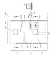
まず、図1〜図3を参照して、本発明の実施の形態に係る自動倉庫であるクリーンストッカ100の構成を説明する。なお、図1は、実施の形態に係るクリーンストッカ100の正面図である。図2は、図1のII−IIにおける断面図である。図3は、図1のIII−IIIにおける断面図である。
First, with reference to FIGS. 1-3, the structure of the
クリーンストッカ100は、半導体工場又は液晶工場などのクリーンルーム内に設置されるものであり、半導体又は液晶基板の露光用のレチクル(荷物)と、レチクルを収納するポッド(ケース)とが別々に保管される。
The
具体的には、クリーンストッカ100は、回転棚110と、レチクル搬送装置120と、ポッド搬送装置130と、ポッドオープナー140と、オートロードポート150と、マニュアルロードポート160と、クリーンガス供給部170と、検知部180と、操作パネル190とを主に備える。また、回転棚110は、上下多段の多数の段を備え、レチクル用回転棚111と、空ポッド用回転棚112と、レチクル入りポッド用回転棚113とに区分されている。なお、レチクル用回転棚111、空ポッド用回転棚112、及びレチクル入りポッド用回転棚113の位置関係は特に限定されない。例えば、図1に示されるように、クリーンな雰囲気を最も必要とするレチクル用回転棚111をクリーンガス供給部170に近い上段に設置し、中段にレチクル入りポッド用回転棚113を設置し、下段に空ポッド用回転棚112を設置するのが好ましい。
Specifically, the
レチクル用回転棚111は、半導体又は液晶基板の露光用のレチクルを保管する棚である。空ポッド用回転棚112は、レチクルが収納されていない空のポッド(以下、「空ポッド」と表記する。)を保管する棚である。レチクル入りポッド用回転棚113は、レチクルを収納した状態のポッド(以下「レチクル入りポッド」と表記する)、言い換えれば、ポッドに収納されたレチクルを一時的に保管する棚である。
The
なお、レチクル用回転棚111及び空ポッド用回転棚112は、レチクルと空ポッドとを別々に保管する保管棚として機能するものである。一方、レチクル入りポッド用回転棚113は、レチクル入りポッドを一時的に保管する仮置棚として機能するものである。
The
なお、空ポッド用回転棚112における空ポッドの保管数は、レチクル用回転棚111におけるレチクルの保管数よりも少なくてもよく、例えば、1/10〜1/100程度としてもよい。さらに、レチクル入りポッド用回転棚113におけるレチクル入りポッドの保管数は、空ポッド用回転棚112における空ポッドの保管数よりさらに少なくてもよく、少なくとも1以上のレチクル入りポッドを収納できればよい。
The number of empty pods stored in the empty pod
レチクル用回転棚111、空ポッド用回転棚112、及びレチクル入りポッド用回転棚113は、それぞれが一体として回転し、各段は独立して回転しないようにしてもよい。又は、収納物の出し入れをより高速で行うため、各棚を上下複数のブロックにさらに分割し、ブロック毎に独立して回転するようにしてもよい。
The
レチクル搬送装置120は、クリーンストッカ100内部の前面一方側(図1では、向かって左側)に設置されている。このレチクル搬送装置120は、レチクル用回転棚111とポッドオープナー140との間でレチクルを搬送する。
より具体的には、レチクル搬送装置120は、2段のアーム121、122の先端にハンド123を設けたもので、水平面内で動作する3個の関節124、125、126を有する。また、レチクル搬送装置120は、昇降ガイド127に沿って昇降する。つまり、このレチクル搬送装置120は、昇降ガイド127の範囲内で上下に昇降し、且つ各関節124、125、126を独立して動作させる。これにより、2段のアーム121、122で到達可能な範囲内で、任意の向きにレチクルを搬送できる。
More specifically, the
ポッド搬送装置130は、クリーンストッカ100内部の前面他方側(図1では、向かって右側)に設置されている。このポッド搬送装置130は、空ポッド用回転棚112とポッドオープナー140との間で空ポッドを搬送したり、ポッドオープナー140とオートロードポート150との間、ポッドオープナー140とマニュアルロードポート160との間、ポッドオープナー140とレチクル入りポッド用回転棚113との間、及びレチクル入りポッド用回転棚113とマニュアルロードポート160との間でレチクル入りポッドを搬送したりする。
The
より具体的には、ポッド搬送装置130は、2段のアーム131、132の先端にハンド133を設けたもので、水平面内で動作する3個の関節134、135、136を有する。また、ポッド搬送装置130は、昇降ガイド137に沿って昇降する。つまり、このポッド搬送装置130は、昇降ガイド137の範囲内で上下に昇降し、且つ各関節134、135、136を独立して動作させる。これにより、2段のアーム131、132で到達可能な範囲内で、任意の向きにポッドを搬送できる。
More specifically, the
ポッドオープナー140は、クリーンストッカ100内部の前面中央部、つまり、レチクル搬送装置120及びポッド搬送装置130の間に配置され、レチクルを空ポッドに収納する収納装置として機能したり、レチクル入りポッドからレチクルを取り出す取り出し装置として機能したりする。処理の詳細は後述する。
The
オートロードポート150は、クリーンストッカ100の前面上部に設けられた天井走行車用ロードポートであり、図示しない天井走行車との間でレチクル入りポッドの入出庫を行うインタフェースである。マニュアルロードポート160は、クリーンストッカ100の前面下部に設けられた作業者用ロードポートであり、作業者との間でレチクル入りポッドの入出庫を行うインタフェースである。
The
クリーンガス供給部170は、クリーンストッカ100の上面に設けられ、例えば、クリーンエア又は窒素などのクリーンガスをダウンフローとして供給する。クリーンガス供給部170は、クリーンガスの生成手段及びファンフィルターユニットを備えたものであってもよいし、あるいはクリーンルームの天井からのクリーンエアをクリーンストッカ100内に取り入れるものであってもよい。
The clean
なお、クリーンストッカ100の内部では、クリーンガス供給部170からのクリーンガスが最初にレチクル用回転棚111に供給され、次いで、レチクル入りポッド用回転棚113、空ポッド用回転棚112の順に供給される。このため裸のレチクルを収納したレチクル用回転棚111を特にクリーンな雰囲気に保ち、レチクルの汚染を防止できる。
In the
検知部180は、操作パネル190及び後述する操作端末10等を介して入力される作業者からの指示を検知する。具体的には、検知部180は、作業者から入力される第1及び第2の指示を検知する。そして、検知部180は、検知した第1及び第2の指示を、回転棚110、レチクル搬送装置120、ポッド搬送装置130、及びポッドオープナー140等に通知する。通知を受けた各構成要素の動作は、後述する。
The
なお、第1の指示は、レチクル用回転棚111に保管されている複数のレチクルのうちの所定のレチクルを搬出することを示す。つまり、第1の指示には、レチクル用回転棚111に保管されているレチクルを特定する情報が含まれている。また、作業者は、操作パネル190及び後述する操作端末10のどちらからでも第1の指示を入力することができるものとする。
The first instruction indicates that a predetermined reticle out of a plurality of reticles stored on the
一方、第2の指示は、レチクル入りポッド用回転棚113に一時的に保管されているレチクル入りポッドを搬出する準備が現実に整ったことを示す。つまり、第2の指示には、レチクル入りポッド用回転棚113に保管されているレチクル入りポッドを特定する情報が含まれている。また、作業者は、操作パネル190からのみ第2の指示を入力することができるものとする。
On the other hand, the second instruction indicates that the preparation for carrying out the pod with the reticle temporarily stored in the rotating pod for
操作パネル190は、例えば、クリーンストッカ100の前面の外壁に取り付けられており、作業者からの指示を受け付ける入力部として機能する。なお、操作パネル190は、作業者からの指示を受付可能なあらゆる構成を採用することができる。例えば、タッチパネル、キーボード、押しボタン、スイッチ等であってもよい。
The
また、クリーンストッカ100には、作業者が操作する操作端末(外部端末)10が通信ネットワーク20を介して接続されている。通常、この操作端末10は、クリーンストッカ100が設置されているクリーンルームの外(オペレータルーム等)に設置されている。そして、作業者は、操作端末10を通じてクリーンストッカ100を遠隔操作することができる。
In addition, an operation terminal (external terminal) 10 operated by an operator is connected to the
次に、図4〜図9を参照して、第1及び第2の指示を検知した場合の処理を説明する。なお、図4は、第1の指示を検知した場合の収納処理を示すフローチャートである。図5は、第2の指示を検知した場合の搬出処理を示すフローチャートである。図6〜図9は、収納処理中におけるポッドオープナー140の状態を示す図である。
Next, processing when the first and second instructions are detected will be described with reference to FIGS. FIG. 4 is a flowchart showing the storage process when the first instruction is detected. FIG. 5 is a flowchart showing the carry-out process when the second instruction is detected. 6 to 9 are views showing the state of the
まず、図4に示されるように、収納処理における検知部180は、作業者から第1の指示が入力されるのを監視している(S11)。そして、検知部180は、第1の指示を検知すると(S11でYes)、当該第1の指示を回転棚110、レチクル搬送装置120、ポッド搬送装置130、及びポッドオープナー140に通知する。
First, as illustrated in FIG. 4, the
次に、第1の指示の通知を受けたポッド搬送装置130は、空ポッド用回転棚112から空ポッドを取得し、ポッドオープナー140に搬入する(S12)。このとき、第1の指示の通知を受けた空ポッド用回転棚112は、ポッド搬送装置130が空ポッドを取得することができるように棚を回転させる。図6は、空のポッド200がポッドオープナー140に搬入された直後の状態を示す図である。図7は、レチクルを受け入れる準備が整った状態を示す図である。
Next, the
まず、ポッド200は、図6に示されるように、上下に分離可能なカバー210及びドア220で構成される。なお、図6には、1枚のレチクルを収納可能な構造のポッド200を例示したが、これに限ることなく、複数のレチクルを収納可能な構造であってもよいことは言うまでもない。
First, as shown in FIG. 6, the
また、ドア220の上面には、レチクルを支持するための複数の突起221が設けられている。ポッドオープナー140は、カバー210を係止する係止部141と、ドア220を載置する載置部142とで構成される。そして、ポッド搬送装置130は、カバー210が係止部141に係止され、ドア220が載置部142に載置されるように、ポッド200をポッドオープナー140に搬入する。
Further, a plurality of
なお、載置部142は、ドア220が載置されている状態で上下に昇降する昇降装置として機能する。そして、載置部142がドア220を載置した状態で降下することにより、図7に示されるように、カバー210とドア220とが上下に分離し、レチクルを収納する準備が整う。
The
次に、第1の指示の通知を受けたレチクル搬送装置120は、第1の指示に示されるレチクルをレチクル用回転棚111から取得し、ポッドオープナー140に搬入する(S13)。このとき、第1の指示の通知を受けたレチクル用回転棚111は、レチクル搬送装置120が第1の指示に示されるレチクルを取得することができるように棚を回転させる。図8は、レチクル230がポッドオープナー140に搬入された直後の状態を示す図である。図9は、レチクル230がポッド200の収納された状態を示す図である。
Next, the
レチクル搬送装置120は、図8に示されるように、ドア220の上面から突出する複数の突起221上に、レチクル230を載置する。次に、載置部142がドア220を載置した状態で上昇することにより、図9に示されるように、レチクル230がポッド200の内部に収納される。
As shown in FIG. 8,
次に、ポッド搬送装置130は、検知部180で検知された第1の指示が操作端末10から入力されたものか否かを判断する(S14)。そして、当該第1の指示が操作端末10から入力されたものである場合(S14でYes)、ポッド搬送装置130は、ポッドオープナー140内のレチクル入りポッドを、レチクル入りポッド用回転棚113に載置する(S15)。このとき、第1の指示の通知を受けたレチクル入りポッド用回転棚113は、ポッド搬送装置130がレチクル入りポッドを載置することができるように棚を回転させる。
Next, the
一方、当該第1の指示が操作端末10から入力されたものでない場合(S14でNo)、ポッド搬送装置130は、ポッドオープナー140内のレチクル入りポッドを、直接(つまり、レチクル入りポッド用回転棚113に一時保管することなく)、オートロードポート150又はマニュアルロードポート160に載置する(S16)。
On the other hand, when the first instruction is not input from the operation terminal 10 (No in S14), the
具体的には、予め定められたスケジュールに基づいて天井走行車等がオートロードポート150からレチクル入りポッドを取得する場合、又は、作業者がクリーンストッカ100に設けられた操作パネル190から第1の指示を入力する場合等が考えられる。これらの場合においては、オートロードポート150又はマニュアルロードポート160のレチクル入りポッドが速やかに取り去られるので、レチクル入りポッド用回転棚113に一時保管する必要はない。
Specifically, when an overhead traveling vehicle or the like acquires a reticle-containing pod from the
次に、図5に示されるように、搬出処理における検知部180は、作業者から第2の指示が入力されるのを監視している(S21)。そして、検知部180は、第2の指示を検知すると(S21でYes)、当該第2の指示を回転棚110及びポッド搬送装置130に通知する。
Next, as illustrated in FIG. 5, the
そして、第2の指示の通知を受けたポッド搬送装置130は、第2の指示に示されるレチクル入りポッドをレチクル入りポッド用回転棚113から取得し、マニュアルロードポート160に載置する(S22)。このとき、第2の指示の通知を受けたレチクル入りポッド用回転棚113は、ポッド搬送装置130が第2の指示に示されるレチクル入りポッドを取得できるように棚を回転させる。
Upon receiving the notification of the second instruction, the
上記構成のクリーンストッカ100によれば、レチクル入りポッドの入出庫をスムーズに行うことができる。例えば、上記構成のクリーンストッカ100は、以下のような状況において、特に有利な効果を奏する。
According to the
第1の例として、作業者Aが第1の指示を入力してから第2の指示を入力するまでの間に、作業者Bがレチクル入りポッドを入庫しようとする場合が考えられる。この場合、クリーンストッカ100は、作業者Aからの第1の指示に基づいて、所定のレチクルをポッドに収納し、レチクル入りポッド用回転棚113に一時的に保管しておく。次に、作業者Bによってマニュアルロードポート160に入庫されたレチクル入りポッドを、ポッドオープナー140でレチクルと空ポッドとに分解し、レチクルをレチクル用回転棚111に、空ポッドを空ポッド用回転棚112に保管する。そして、作業者Aからの第2の指示に基づいて、レチクル入りポッドをレチクル入りポッド用回転棚113からマニュアルロードポート160に移載する。
As a first example, there may be a case where worker B tries to store a pod containing a reticle between when worker A inputs a first instruction and when he inputs a second instruction. In this case, the
このように、作業者Aが出庫を指示(第1の指示を入力)してから現実にレチクル入りポッドを取りに来る(第2の指示を入力)までに長時間を要したとしても、他の作業者Bによるレチクル入りポッドの入庫を妨げることがない。なお、この場合、レチクル入りポッド用回転棚113は、少なくとも1以上のレチクル入りポッドを保管することができればよい。
In this way, even if it takes a long time from when worker A instructs to leave (inputs the first instruction) until he actually picks up the pod with the reticle (inputs the second instruction), This prevents the worker B from entering the reticle-containing pod. In this case, the reticle-containing
次に、第2の例として、作業者A、Bがこの順に操作端末10を操作してレチクルの出庫を指示し、作業者B、Aの順にクリーンストッカ100の設置場所に到着した場合が考えられる。この場合、クリーンストッカ100は、作業者A、Bの第1の指示に基づいて、レチクル入りポッドをレチクル入りポッド用回転棚113に一時的に保管しておく。そして、作業者Bの第2の指示に基づいて、作業者Bが取得すべきレチクル入りポッドをレチクル入りポッド用回転棚113からマニュアルロードポート160に移載する。続いて、作業者Aの第2の指示に基づいて、作業者Aが取得すべきレチクル入りポッドをレチクル入りポッド用回転棚113からマニュアルロードポート160に移載する。
Next, as a second example, it is considered that the workers A and B operate the
このように、複数の作業者A、Bがレチクルを出庫しようとする場合において、第1の指示の入力順と、第2の指示の入力順とが入れ替わった場合でもスムーズに出庫をすることが可能となる。なお、この場合、レチクル入りポッド用回転棚113は、複数のレチクル入りポッド(作業者の数と同数以上)を保管することができなければならない。
As described above, when a plurality of workers A and B try to leave a reticle, even when the input order of the first instruction and the input order of the second instruction are switched, the goods can be smoothly output. It becomes possible. In this case, the
なお、上記の実施の形態において、各構成要素の具体的な構成は特に限定されない。例えば、仮置き棚としてのレチクル入りポッド用回転棚113は、保管すべきポッド数が少ないので、回転棚ではなく固定棚としてもよい。この場合の仮置き棚は、例えば、オートロードポート150及びマニュアルロードポート160の間の空間に設置してもよいし、ポッドオープナー140の下部等に設置してもよい。
In the above embodiment, the specific configuration of each component is not particularly limited. For example, the reticle-containing
又は、操作パネル190は、クリーンストッカ100の前面外壁でなくとも、クリーンストッカ100に近接して設置される端末等、作業者が指示を入力した後速やかにレチクル入りポッドを取得できる位置であればよい。
Alternatively, the
さらには、入力部は、作業者の能動的な指示を受け付ける操作パネル190に限られず、作業者の到着を検出するセンサ等であってもよい。より具体的には、第1の指示には、さらに当該第1の指示を入力した作業者を特定する情報(作業者ID等)が含まれており、入力部は、作業者が携帯するRFIDタグ等から作業者IDを取得することによって、第1の指示を入力した作業者がクリーンストッカ100の設置場所に到着した(つまり、レチクル入りポッドを搬出する準備が現実に整った)ことを検出してもよい。
Furthermore, the input unit is not limited to the
また、本発明は、レチクルを収納するクリーンストッカ100のみならず、荷物と荷物を収納する容器とを別々に保管し、出庫時に荷物を容器に収納する構成を備えるあらゆる自動倉庫に適用することができる。
Further, the present invention can be applied not only to the
以上、図面を参照してこの発明の実施形態を説明したが、この発明は、図示した実施形態のものに限定されない。図示した実施形態に対して、この発明と同一の範囲内において、あるいは均等の範囲内において、種々の修正や変形を加えることが可能である。 As mentioned above, although embodiment of this invention was described with reference to drawings, this invention is not limited to the thing of embodiment shown in figure. Various modifications and variations can be made to the illustrated embodiment within the same range or equivalent range as the present invention.
本発明は、荷物と荷物を収納する容器とを別々に保管し、出庫時に荷物を容器に収納する自動倉庫に有利に利用される。 INDUSTRIAL APPLICABILITY The present invention is advantageously used in an automatic warehouse in which a luggage and a container for storing the luggage are stored separately, and the luggage is stored in the container at the time of delivery.
10 操作端末
20 通信ネットワーク
100 クリーンストッカ
110 回転棚
111 レチクル用回転棚
112 空ポッド用回転棚
113 レチクル入りポッド用回転棚
120 レチクル搬送装置
121,122,131,132 アーム
123,133 ハンド
124,125,126,134,135,136 関節
127,137 昇降ガイド
130 ポッド搬送装置
140 ポッドオープナー
141 係止部
142 載置部
150 オートロードポート
160 マニュアルロードポート
170 クリーンガス供給部
180 検知部
190 操作パネル
200 ポッド
210 カバー
220 ドア
221 突起
230 レチクルDESCRIPTION OF
Claims (5)
前記ケースに収納された前記物品を作業者に供給するロードポートと、
前記ケースに収納された前記物品を、前記ロードポートに移載するまで一時的に保管する仮置棚と、
作業者からの指示を検知する検知部と、
前記複数の物品のうちの所定の物品の搬出準備を示す第1の指示が前記検知部で検知された場合に、前記保管棚から前記所定の物品と前記ケースとを取得し、取得した前記所定の物品を前記ケースに収納する収納装置と、
前記収納装置で前記ケースに収納された前記所定の物品を前記仮置棚に載置すると共に、前記所定の物品を搬出することを示す第2の指示が前記検知部で検知された場合に、前記ケースに収納された前記所定の物品を前記仮置棚から前記ロードポートに移載する移載装置とを備える
自動倉庫。 A storage shelf for separately storing a plurality of articles and a case for storing at least one of the plurality of articles;
A load port for supplying the article stored in the case to an operator;
A temporary storage shelf for temporarily storing the articles stored in the case until they are transferred to the load port;
A detection unit for detecting an instruction from the worker;
Said predetermined the first indication of unloading preparation of certain articles of the plurality of articles when it is detected by the detecting unit acquires said from the storage shelf to the predetermined article case were obtained A storage device for storing the article in the case;
While placing the predetermined article housed in the casing in the storage device to the provisional shelf, if the second indication of the Turkey to unloading the predetermined article is detected by the detecting unit And a transfer device that transfers the predetermined article stored in the case from the temporary storage shelf to the load port.
前記移載装置は、作業者によって前記入力部に入力される前記第2の指示が前記検知部で検知された場合に、前記ケースに収納された前記所定の物品を前記仮置棚から前記ロードポートに移載する
請求項1に記載の自動倉庫。 The automatic warehouse further includes an input unit for an operator to input the second instruction,
The transfer device is configured to load the predetermined article stored in the case from the temporary shelf when the second instruction input to the input unit by an operator is detected by the detection unit. The automatic warehouse according to claim 1, which is transferred to a port.
前記第2の指示は、前記仮置棚に一時的に保管されている前記複数の物品のうち、搬出すべき物品を特定する情報を含み、
前記移載装置は、前記検知部で検知された前記第2の指示によって特定される前記物品を、前記仮置棚から前記ロードポートに移載する
請求項1又は2に記載の自動倉庫。 The temporary storage shelf stores a plurality of the articles stored in the case,
The second instruction includes information for specifying an article to be carried out of the plurality of articles temporarily stored in the temporary storage shelf,
The automatic warehouse according to claim 1 or 2, wherein the transfer device transfers the article specified by the second instruction detected by the detection unit from the temporary storage shelf to the load port.
前記外部端末は、作業者が前記第1の指示を入力するための端末であり、
前記収納装置は、前記外部端末に入力された前記第1の指示が前記検知部で検知された場合に、前記ケースに収納された前記所定の物品を前記仮置棚に載置する
請求項1〜3のいずれか1項に記載の自動倉庫。 An external terminal installed in a remote place is connected to the automatic warehouse via a communication network,
The external terminal is a terminal for an operator to input the first instruction,
The storage device places the predetermined article stored in the case on the temporary storage shelf when the detection unit detects the first instruction input to the external terminal. The automatic warehouse of any one of -3.
前記複数の物品のうちの所定の物品の搬出準備を示す第1の指示が前記検知部で検知された場合に、前記保管棚から前記所定の物品と前記ケースとを取得し、取得した前記所定の物品を前記ケースに収納し、前記ケースに収納された前記所定の物品を前記仮置棚に載置するステップと、
前記所定の物品を搬出することを示す第2の指示が前記検知部で検知された場合に、前記ケースに収納された前記所定の物品を前記仮置棚から前記ロードポートに移載するステップとを含む
物品搬出方法。 A storage shelf that separately stores a plurality of articles and a case for storing at least one of the plurality of articles, a load port that supplies the articles stored in the case to an operator, An automatic warehouse comprising a temporary storage shelf for temporarily storing the article stored in a case until it is transferred to the load port, and a detection unit that detects an instruction from an operator stores the article in the case. A method for carrying out the article,
Said predetermined the first indication of unloading preparation of certain articles of the plurality of articles when it is detected by the detecting unit acquires said from the storage shelf to the predetermined article case were obtained Storing the article in the case, and placing the predetermined article stored in the case on the temporary shelf;
If the second indication of the Turkey to unloading the predetermined article is detected by the detecting unit, it is transferred to the load port of the predetermined article housed in the casing from the temporary shelves And a method for carrying out the article.
Priority Applications (1)
| Application Number | Priority Date | Filing Date | Title |
|---|---|---|---|
| JP2012533833A JP5549736B2 (en) | 2010-09-13 | 2011-07-25 | Automatic warehouse and article delivery method |
Applications Claiming Priority (4)
| Application Number | Priority Date | Filing Date | Title |
|---|---|---|---|
| JP2010204795 | 2010-09-13 | ||
| JP2010204795 | 2010-09-13 | ||
| PCT/JP2011/004162 WO2012035693A1 (en) | 2010-09-13 | 2011-07-25 | Automated warehouse and article removal method |
| JP2012533833A JP5549736B2 (en) | 2010-09-13 | 2011-07-25 | Automatic warehouse and article delivery method |
Publications (2)
| Publication Number | Publication Date |
|---|---|
| JPWO2012035693A1 JPWO2012035693A1 (en) | 2014-01-20 |
| JP5549736B2 true JP5549736B2 (en) | 2014-07-16 |
Family
ID=45831189
Family Applications (1)
| Application Number | Title | Priority Date | Filing Date |
|---|---|---|---|
| JP2012533833A Active JP5549736B2 (en) | 2010-09-13 | 2011-07-25 | Automatic warehouse and article delivery method |
Country Status (7)
| Country | Link |
|---|---|
| US (1) | US8948908B2 (en) |
| EP (1) | EP2618214B1 (en) |
| JP (1) | JP5549736B2 (en) |
| KR (1) | KR101433214B1 (en) |
| CN (1) | CN103119517B (en) |
| TW (1) | TWI484535B (en) |
| WO (1) | WO2012035693A1 (en) |
Families Citing this family (10)
| Publication number | Priority date | Publication date | Assignee | Title |
|---|---|---|---|---|
| KR101463135B1 (en) * | 2011-05-02 | 2014-11-21 | 무라다기카이가부시끼가이샤 | Orientation adjustment device, and orientation adjustment method |
| JP5709011B2 (en) * | 2011-12-26 | 2015-04-30 | 株式会社ダイフク | Goods storage facility |
| CN103538045B (en) * | 2013-09-29 | 2016-05-25 | 昆山中士设备工业有限公司 | Be convenient to automation mechanized operation and get the shelf of part |
| CN103538047A (en) * | 2013-09-29 | 2014-01-29 | 昆山中士设备工业有限公司 | Goods shelf suitable for mechanical arm |
| CN105899444B (en) * | 2014-01-07 | 2017-11-10 | 村田机械株式会社 | The control method of shifting apparatus and shifting apparatus |
| JP6217855B2 (en) * | 2014-06-16 | 2017-10-25 | 村田機械株式会社 | Purge apparatus, purge system, purge method, and control method in purge system |
| US9786536B2 (en) * | 2015-12-07 | 2017-10-10 | Microchip Technology Incorporated | Reticle rack system |
| US10406562B2 (en) * | 2017-07-21 | 2019-09-10 | Applied Materials, Inc. | Automation for rotary sorters |
| KR102046814B1 (en) * | 2019-06-11 | 2019-11-20 | 이재환 | System for Managing Warehouse of Storing Goods |
| KR102481920B1 (en) * | 2019-12-19 | 2022-12-26 | 캐논 톡키 가부시키가이샤 | Object storage device and film-forming apparatus having the same |
Citations (8)
| Publication number | Priority date | Publication date | Assignee | Title |
|---|---|---|---|---|
| JPS62217036A (en) * | 1986-03-18 | 1987-09-24 | Mitsubishi Electric Corp | Stocker |
| JPS63127906A (en) * | 1986-11-17 | 1988-05-31 | Mitsubishi Electric Corp | Custody shelf |
| JPS63267601A (en) * | 1987-04-24 | 1988-11-04 | Mitsubishi Electric Corp | Mask management facility |
| JPH0494306A (en) * | 1990-08-10 | 1992-03-26 | Fujitsu Ltd | Carried material control system |
| JP2001077173A (en) * | 1999-09-02 | 2001-03-23 | Canon Inc | Semiconductor manufacturing apparatus and manufacture of device |
| JP2007165367A (en) * | 2005-12-09 | 2007-06-28 | Izumi Akiyama | Sheet-fed work conveyance system |
| JP2008030914A (en) * | 2006-07-31 | 2008-02-14 | Murata Mach Ltd | Clean stocker and article storage method |
| JP2010509785A (en) * | 2006-11-15 | 2010-03-25 | ダイナミック マイクロシステムズ セミコンダクター イクイップメント ゲーエムベーハー | Removable compartment for workpiece stocker |
Family Cites Families (4)
| Publication number | Priority date | Publication date | Assignee | Title |
|---|---|---|---|---|
| JP3513437B2 (en) * | 1999-09-01 | 2004-03-31 | キヤノン株式会社 | Substrate management method and semiconductor exposure apparatus |
| JP4221603B2 (en) * | 2005-03-31 | 2009-02-12 | 村田機械株式会社 | Overhead traveling vehicle system |
| US7751919B2 (en) * | 2006-08-19 | 2010-07-06 | Dynamic Micro Systems | Method for operating equipment using buffer station having emergency access |
| JP5083278B2 (en) * | 2009-06-15 | 2012-11-28 | 村田機械株式会社 | Automatic warehouse in front of equipment |
-
2011
- 2011-07-25 KR KR1020137001789A patent/KR101433214B1/en active IP Right Grant
- 2011-07-25 US US13/819,561 patent/US8948908B2/en not_active Expired - Fee Related
- 2011-07-25 CN CN201180042795.7A patent/CN103119517B/en not_active Expired - Fee Related
- 2011-07-25 EP EP11824713.9A patent/EP2618214B1/en active Active
- 2011-07-25 WO PCT/JP2011/004162 patent/WO2012035693A1/en active Application Filing
- 2011-07-25 JP JP2012533833A patent/JP5549736B2/en active Active
- 2011-09-13 TW TW100132825A patent/TWI484535B/en not_active IP Right Cessation
Patent Citations (8)
| Publication number | Priority date | Publication date | Assignee | Title |
|---|---|---|---|---|
| JPS62217036A (en) * | 1986-03-18 | 1987-09-24 | Mitsubishi Electric Corp | Stocker |
| JPS63127906A (en) * | 1986-11-17 | 1988-05-31 | Mitsubishi Electric Corp | Custody shelf |
| JPS63267601A (en) * | 1987-04-24 | 1988-11-04 | Mitsubishi Electric Corp | Mask management facility |
| JPH0494306A (en) * | 1990-08-10 | 1992-03-26 | Fujitsu Ltd | Carried material control system |
| JP2001077173A (en) * | 1999-09-02 | 2001-03-23 | Canon Inc | Semiconductor manufacturing apparatus and manufacture of device |
| JP2007165367A (en) * | 2005-12-09 | 2007-06-28 | Izumi Akiyama | Sheet-fed work conveyance system |
| JP2008030914A (en) * | 2006-07-31 | 2008-02-14 | Murata Mach Ltd | Clean stocker and article storage method |
| JP2010509785A (en) * | 2006-11-15 | 2010-03-25 | ダイナミック マイクロシステムズ セミコンダクター イクイップメント ゲーエムベーハー | Removable compartment for workpiece stocker |
Also Published As
| Publication number | Publication date |
|---|---|
| CN103119517A (en) | 2013-05-22 |
| EP2618214A1 (en) | 2013-07-24 |
| KR101433214B1 (en) | 2014-08-22 |
| EP2618214B1 (en) | 2021-01-27 |
| CN103119517B (en) | 2015-05-13 |
| TW201233610A (en) | 2012-08-16 |
| JPWO2012035693A1 (en) | 2014-01-20 |
| WO2012035693A1 (en) | 2012-03-22 |
| TWI484535B (en) | 2015-05-11 |
| KR20130050954A (en) | 2013-05-16 |
| US20130158701A1 (en) | 2013-06-20 |
| EP2618214A4 (en) | 2014-10-01 |
| US8948908B2 (en) | 2015-02-03 |
Similar Documents
| Publication | Publication Date | Title |
|---|---|---|
| JP5549736B2 (en) | Automatic warehouse and article delivery method | |
| JP6044467B2 (en) | Storage system | |
| JP6229729B2 (en) | Storehouse | |
| US7887277B2 (en) | Reticle storage pod (RSP) transport system utilizing FOUP adapter plate | |
| JP5318005B2 (en) | Substrate processing apparatus, stocker apparatus, and substrate container transport method | |
| KR101184789B1 (en) | Coating, developing apparatus | |
| KR20130118236A (en) | Substrate treatment apparatus, substrate treatment method and storage medium | |
| JP2011140366A (en) | Conveying vehicle system | |
| US20090022575A1 (en) | Article storing apparatus | |
| JP5586739B2 (en) | Substrate processing apparatus, stocker apparatus, and substrate container transport method | |
| JP2010040979A (en) | Storage warehouse system | |
| JP2010013250A (en) | Conveyance system and computer program | |
| TWI527084B (en) | Direction adjustment device and direction adjustment method | |
| TW202116650A (en) | System and method for automated wafer carrier handling | |
| CN116344384A (en) | Article storage facility and logistics system of semiconductor manufacturing factory provided with same | |
| KR102166348B1 (en) | Method of controlling operations of transport apparatus | |
| JP2009124078A (en) | Substrate processing apparatus | |
| WO2023203911A1 (en) | Transport system | |
| KR20220026373A (en) | Transfer method and transfer apparatus | |
| JP2009035414A (en) | Inter-process conveying system between different stories | |
| KR20200118787A (en) | Method of controlling operations of transport apparatus | |
| JP2008100801A (en) | Substrate storage warehouse | |
| JP2009012965A (en) | Stocker device |
Legal Events
| Date | Code | Title | Description |
|---|---|---|---|
| A521 | Request for written amendment filed |
Free format text: JAPANESE INTERMEDIATE CODE: A523 Effective date: 20131009 |
|
| TRDD | Decision of grant or rejection written | ||
| A01 | Written decision to grant a patent or to grant a registration (utility model) |
Free format text: JAPANESE INTERMEDIATE CODE: A01 Effective date: 20140422 |
|
| A61 | First payment of annual fees (during grant procedure) |
Free format text: JAPANESE INTERMEDIATE CODE: A61 Effective date: 20140505 |
|
| R150 | Certificate of patent or registration of utility model |
Ref document number: 5549736 Country of ref document: JP Free format text: JAPANESE INTERMEDIATE CODE: R150 |
|
| R250 | Receipt of annual fees |
Free format text: JAPANESE INTERMEDIATE CODE: R250 |
|
| R250 | Receipt of annual fees |
Free format text: JAPANESE INTERMEDIATE CODE: R250 |
|
| R250 | Receipt of annual fees |
Free format text: JAPANESE INTERMEDIATE CODE: R250 |
|
| R250 | Receipt of annual fees |
Free format text: JAPANESE INTERMEDIATE CODE: R250 |
|
| R250 | Receipt of annual fees |
Free format text: JAPANESE INTERMEDIATE CODE: R250 |
|
| R250 | Receipt of annual fees |
Free format text: JAPANESE INTERMEDIATE CODE: R250 |
|
| R250 | Receipt of annual fees |
Free format text: JAPANESE INTERMEDIATE CODE: R250 |