JP5539104B2 - Photoelectric conversion device and imaging system using the same - Google Patents
Photoelectric conversion device and imaging system using the same Download PDFInfo
- Publication number
- JP5539104B2 JP5539104B2 JP2010185289A JP2010185289A JP5539104B2 JP 5539104 B2 JP5539104 B2 JP 5539104B2 JP 2010185289 A JP2010185289 A JP 2010185289A JP 2010185289 A JP2010185289 A JP 2010185289A JP 5539104 B2 JP5539104 B2 JP 5539104B2
- Authority
- JP
- Japan
- Prior art keywords
- photoelectric conversion
- semiconductor region
- region
- transistor
- conversion element
- Prior art date
- Legal status (The legal status is an assumption and is not a legal conclusion. Google has not performed a legal analysis and makes no representation as to the accuracy of the status listed.)
- Active
Links
- 238000006243 chemical reaction Methods 0.000 title claims description 124
- 238000003384 imaging method Methods 0.000 title description 21
- 239000004065 semiconductor Substances 0.000 claims description 153
- 239000000758 substrate Substances 0.000 claims description 28
- 238000009825 accumulation Methods 0.000 claims description 13
- 230000003321 amplification Effects 0.000 claims description 13
- 238000003199 nucleic acid amplification method Methods 0.000 claims description 13
- 238000005468 ion implantation Methods 0.000 claims description 8
- 238000003860 storage Methods 0.000 claims description 8
- 238000000034 method Methods 0.000 claims description 3
- 238000002955 isolation Methods 0.000 description 11
- 238000009792 diffusion process Methods 0.000 description 10
- 230000004888 barrier function Effects 0.000 description 7
- 230000035945 sensitivity Effects 0.000 description 6
- 230000006866 deterioration Effects 0.000 description 5
- 238000000926 separation method Methods 0.000 description 5
- 238000010586 diagram Methods 0.000 description 4
- 230000006870 function Effects 0.000 description 4
- 150000002500 ions Chemical class 0.000 description 4
- 229920002120 photoresistant polymer Polymers 0.000 description 3
- 238000012937 correction Methods 0.000 description 2
- 238000002513 implantation Methods 0.000 description 2
- 239000012535 impurity Substances 0.000 description 1
- 238000010884 ion-beam technique Methods 0.000 description 1
- 238000004519 manufacturing process Methods 0.000 description 1
- 239000011159 matrix material Substances 0.000 description 1
- 230000003287 optical effect Effects 0.000 description 1
- 230000003647 oxidation Effects 0.000 description 1
- 238000007254 oxidation reaction Methods 0.000 description 1
- 230000003071 parasitic effect Effects 0.000 description 1
Images


Classifications
-
- H—ELECTRICITY
- H01—ELECTRIC ELEMENTS
- H01L—SEMICONDUCTOR DEVICES NOT COVERED BY CLASS H10
- H01L27/00—Devices consisting of a plurality of semiconductor or other solid-state components formed in or on a common substrate
- H01L27/14—Devices consisting of a plurality of semiconductor or other solid-state components formed in or on a common substrate including semiconductor components sensitive to infrared radiation, light, electromagnetic radiation of shorter wavelength or corpuscular radiation and specially adapted either for the conversion of the energy of such radiation into electrical energy or for the control of electrical energy by such radiation
- H01L27/144—Devices controlled by radiation
- H01L27/146—Imager structures
- H01L27/148—Charge coupled imagers
- H01L27/14831—Area CCD imagers
-
- H—ELECTRICITY
- H01—ELECTRIC ELEMENTS
- H01L—SEMICONDUCTOR DEVICES NOT COVERED BY CLASS H10
- H01L27/00—Devices consisting of a plurality of semiconductor or other solid-state components formed in or on a common substrate
- H01L27/14—Devices consisting of a plurality of semiconductor or other solid-state components formed in or on a common substrate including semiconductor components sensitive to infrared radiation, light, electromagnetic radiation of shorter wavelength or corpuscular radiation and specially adapted either for the conversion of the energy of such radiation into electrical energy or for the control of electrical energy by such radiation
- H01L27/144—Devices controlled by radiation
- H01L27/146—Imager structures
- H01L27/14601—Structural or functional details thereof
- H01L27/14603—Special geometry or disposition of pixel-elements, address-lines or gate-electrodes
Landscapes
- Physics & Mathematics (AREA)
- Engineering & Computer Science (AREA)
- Power Engineering (AREA)
- Electromagnetism (AREA)
- Condensed Matter Physics & Semiconductors (AREA)
- General Physics & Mathematics (AREA)
- Computer Hardware Design (AREA)
- Microelectronics & Electronic Packaging (AREA)
- Solid State Image Pick-Up Elements (AREA)
- Light Receiving Elements (AREA)
Description
本件は光電変換装置の分離の構造に関する。 This case relates to a structure for separating photoelectric conversion devices.
CCD型やCMOS型の光電変換装置は多くのデジタルスチルカメラやデジタルカムコーダーに用いられている。近年、光電変換装置は画素の縮小化がなされており、それによって隣接の画素への電荷の混合(クロストーク)への対策が検討されている。 CCD-type and CMOS-type photoelectric conversion devices are used in many digital still cameras and digital camcorders. In recent years, pixels of photoelectric conversion devices have been reduced in size, and measures against charge mixing (crosstalk) to adjacent pixels have been studied.
特許文献1では、隣接する画素間での電荷の混合を防ぐための分離用のバリアとなるP型ウエル領域を、光電変換素子のN型ウエル領域に合わせて深い領域に形成する構成が開示されている。 Patent Document 1 discloses a configuration in which a P-type well region serving as a separation barrier for preventing charge mixing between adjacent pixels is formed in a deep region in accordance with the N-type well region of the photoelectric conversion element. ing.
しかしながら、特許文献1に開示されているP型のウエル領域では、画素の縮小化に伴い新たな課題が生じうる。それは、画素が縮小された時に、光電変換素子分離用のウエル領域によって光電変換素子の領域が低減し、光電変換素子の感度が低下してしまう可能性があることである。例えば、光電変換素子分離用のウエル領域が、信号電荷に対して障壁となるP型半導体領域の場合、光電変換素子のN型半導体領域を打ち消してしまう。 However, in the P-type well region disclosed in Patent Document 1, a new problem may occur as the pixels are reduced. That is, when the pixel is reduced, the photoelectric conversion element region may be reduced by the photoelectric conversion element isolation well region, and the sensitivity of the photoelectric conversion element may be reduced. For example, when the well region for photoelectric conversion element isolation is a P-type semiconductor region that becomes a barrier against signal charges, the N-type semiconductor region of the photoelectric conversion element is canceled out.
また、光電変換素子分離用のP型ウエル領域の幅を狭くすると、P型ウエル領域を形成する際のイオン注入において不純物が所望の深さに注入されない可能性がある。すると、光電変換素子の周辺に光電変換素子の電荷を読み出すためのトランジスタなどが設けられており、光電変換素子分離用のP型のウエル領域にトランジスタが配置される場合において、トランジスタの閾値にばらつきが生じうる。トランジスタの閾値がばらつくと、ダイナミックレンジが狭くなる等のトランジスタ性能の低下が生じてしまう。 Further, if the width of the P-type well region for photoelectric conversion element separation is narrowed, there is a possibility that impurities are not implanted at a desired depth in ion implantation when forming the P-type well region. Then, a transistor for reading out the charge of the photoelectric conversion element is provided around the photoelectric conversion element, and the threshold value of the transistor varies when the transistor is arranged in the P-type well region for photoelectric conversion element separation. Can occur. If the threshold value of the transistor varies, the transistor performance will be degraded, such as a narrow dynamic range.
そこで、本発明においては、光電変換素子の感度を維持しつつ、トランジスタの性能低下を抑制することが可能な光電変換装置を提供することを目的とする。 In view of the above, an object of the present invention is to provide a photoelectric conversion device capable of suppressing deterioration in performance of a transistor while maintaining the sensitivity of the photoelectric conversion element.
本発明の光電変換装置は、第1導電型の第1の電荷蓄積領域を含む第1の光電変換素子と、前記第1の光電変換素子に対して第1方向に沿って配置され、前記第1導電型の第2の電荷蓄積領域を含む第2の光電変換素子と、前記第1の光電変換素子に対して前記第1方向と交わる第2方向に沿って配置され、前記第1導電型の第3の電荷蓄積領域を含む第の光電変換素子と、前記第1の光電変換素子にて生じた信号電荷を読み出すためのトランジスタと、が配置された前記第1導電型と反対導電型の第2導電型の半導体領域を含む半導体基板を有する光電変換装置において、前記第1の電荷蓄積領域と前記第2の電荷蓄積領域との間の前記第2導電型の半導体領域にイオン注入によって形成され、前記半導体基板の深さ方向において前記トランジスタのチャネル部となる部分よりも深くに位置し、前記第2の方向に沿って配され、第1の幅を有する前記第2導電型の第1の半導体領域と、前記第1の電荷蓄積領域と前記第2の電荷蓄積領域との間の前記第2導電型の半導体領域にイオン注入によって形成され、前記半導体基板の表面へ投影した時に、前記第2導電型の半導体領域の前記トランジスタが配された領域に配置され、前記半導体領域基板の深さ方向において前記トランジスタのチャネル部となる部分の下部に位置し、前記第1の幅よりも広く、前記トランジスタのチャネル部となる部分の幅よりも広い第2の幅を有する前記第2導電型の第2の半導体領域と、前記第1の電荷蓄積領域と前記第3の電荷蓄積領域との間の前記第2導電型の半導体領域にイオン注入によって形成され、前記半導体基板の深さ方向において前記トランジスタのチャネル部となる部分よりも深くに位置し、前記第1の方向に沿って配され、前記第2の幅よりも狭い第3の幅を有する前記第2導電型の第3の半導体領域と、を有し、前記半導体基板の表面へ投影した時に、前記第1の半導体領域と前記第3の半導体領域は、格子状に配置し、前記半導体基板の表面へ投影した時に、前記第2の半導体領域は、前記第1の半導体領域が構成する前記格子の辺の一部である。 The photoelectric conversion device of the present invention is arranged along a first direction with respect to the first photoelectric conversion element including a first charge accumulation region of a first conductivity type, and with respect to the first photoelectric conversion element. A second photoelectric conversion element including a second charge accumulation region of one conductivity type, and a second photoelectric conversion element disposed along a second direction intersecting the first direction with respect to the first photoelectric conversion element; A first photoelectric conversion element including the third charge accumulation region and a transistor for reading out signal charges generated in the first photoelectric conversion element are disposed of a conductivity type opposite to the first conductivity type. in the photoelectric conversion device having a semiconductor substrate including a semiconductor region of a second conductivity type, formed by ion implantation into the semiconductor region of the second conductivity type between the first charge accumulation region and the second charge accumulation region In the depth direction of the semiconductor substrate. Located deeper than the portion to be a channel portion of register, the arranged along a second direction, said first semiconductor region of a second conductivity type having a first width, the first charge accumulation The transistor of the second conductivity type semiconductor region is formed by ion implantation in the second conductivity type semiconductor region between the region and the second charge storage region and projected onto the surface of the semiconductor substrate. A width of a portion that is located in a lower portion of the channel portion of the transistor in the depth direction of the semiconductor region substrate and that is wider than the first width and that becomes the channel portion of the transistor A second conductive type second semiconductor region having a second width wider than the second conductive type semiconductor region, and the second conductive type semiconductor region between the first charge storage region and the third charge storage region. By ion implantation And a third width that is located deeper than the portion that becomes the channel portion of the transistor in the depth direction of the semiconductor substrate, is disposed along the first direction, and is narrower than the second width. a third semiconductor region of the second conductivity type, a possess having, when projected onto the surface of the semiconductor substrate, the third semiconductor region and the first semiconductor region is arranged in a grid, wherein When projected onto the surface of the semiconductor substrate, the second semiconductor region is a part of the side of the lattice formed by the first semiconductor region .
光電変換素子の感度を維持しつつ、トランジスタの性能低下を抑制することが可能な光電変換装置を提供することが可能となる。 It is possible to provide a photoelectric conversion device capable of suppressing deterioration in the performance of the transistor while maintaining the sensitivity of the photoelectric conversion element.
本発明の光電変換装置は基板と、基板に配された複数の光電変換素子と、光電変換素子にて生じた信号電荷を転送するためのトランジスタと、転送された信号電荷を読み出すための複数のトランジスタと、を有する。複数の光電変換素子は、第1の光電変換素子と、第1の光電変換素子に隣接する第2の光電変換素子とを有する。そして、第1の光電変換素子と第2の光電変換素子との間に配された信号電荷が少数キャリアとなる第1導電型の第1の半導体領域と、転送された信号電荷を読み出すための複数のトランジスタが配された領域に配された第1導電型の第2の半導体領域を有する。この第2の半導体領域は第1導電型の第1の半導体領域よりも幅が広い。 The photoelectric conversion device of the present invention includes a substrate, a plurality of photoelectric conversion elements arranged on the substrate, a transistor for transferring signal charges generated in the photoelectric conversion elements, and a plurality of signals for reading the transferred signal charges And a transistor. The plurality of photoelectric conversion elements include a first photoelectric conversion element and a second photoelectric conversion element adjacent to the first photoelectric conversion element. Then, a first semiconductor region of the first conductivity type in which the signal charge disposed between the first photoelectric conversion element and the second photoelectric conversion element becomes a minority carrier, and for reading the transferred signal charge The semiconductor device has a second semiconductor region of the first conductivity type arranged in a region where a plurality of transistors are arranged. The second semiconductor region is wider than the first conductivity type first semiconductor region.
このような構成を有することで、光電変換素子の感度を維持しつつ、トランジスタの性能低下を抑制することが可能となる。 With such a configuration, it is possible to suppress deterioration in the performance of the transistor while maintaining the sensitivity of the photoelectric conversion element.
以下、本発明の実施例について図面を用いて詳細に説明する。 Hereinafter, embodiments of the present invention will be described in detail with reference to the drawings.
(画素回路の一例)
まず、本発明が適用されうる画素回路の一例について説明する。図2(A)は本発明が適用されうる画素回路の一例を示した回路図であり、図2(B)はその画素回路の1画素分の平面レイアウトを示す平面図である。以下、信号電荷が電子の場合を説明する。
(Example of pixel circuit)
First, an example of a pixel circuit to which the present invention can be applied will be described. FIG. 2A is a circuit diagram illustrating an example of a pixel circuit to which the present invention can be applied, and FIG. 2B is a plan view illustrating a planar layout for one pixel of the pixel circuit. Hereinafter, the case where the signal charge is an electron will be described.
図2(A)において、画素ユニット(PIXEL UNIT)は、少なくとも2つの画素を有する。画素は少なくとも1つの光電変換素子を有する。図2(A)において、光電変換素子であるフォトダイオード100(100a及び100b)と、転送MOSトランジスタ101(101a及び101b)とを有する。そして、リセットMOSトランジスタ102と、増幅MOSトランジスタ103と、選択MOSトランジスタ105とを有する。つまり、2つの画素、即ち2つのフォトダイオードがリセットMOSトランジスタ102と、増幅MOSトランジスタ103と、選択MOSトランジスタ105とを共有化している。それぞれの転送MOSトランジスタ101はそれぞれの光電変換素子100にて生じた信号電荷を浮遊拡散部104へ転送する。増幅MOSトランジスタ103は浮遊拡散部104の電位に応じた出力を、選択MOSトランジスタ105を介して出力線106へ出力する。増幅MOSトランジスタ103はソースフォロワ回路の一部であり、そのゲート電極は浮遊拡散部104と接続されている。リセットMOSトランジスタ102は、増幅MOSトランジスタ103のゲート電極のノード、すなわち浮遊拡散部104を規定の電位(リセット電位)にリセットする。転送MOSトランジスタ101aには転送制御信号TX1が、転送MOSトランジスタ101bには転送制御信号TX2が供給される。リセットMOSトランジスタ102にはリセット制御信号RESが、選択MOSトランジスタ105には選択制御信号SELが供給される。各制御信号によって上述の信号電荷の読み出しが制御される。光電変換装置には、このような画素ユニットが1次元もしくは2次元に配列し、撮像領域を構成している。なお、画素ユニットは2つの画素を有していなくてもよく、任意の構成が適用可能である。
In FIG. 2A, the pixel unit (PIXEL UNIT) includes at least two pixels. The pixel has at least one photoelectric conversion element. In FIG. 2A, a photodiode 100 (100a and 100b) which is a photoelectric conversion element and a transfer MOS transistor 101 (101a and 101b) are included. The
図2(B)は、図2(A)の回路を有する光電変換装置の1画素の平面レイアウトを示す。図2(B)では、図2(A)の101bに対応する光電変換素子200が配置されている。201は転送MOSトランジスタ101bのゲート電極、202はリセットMOSトランジスタ102のゲート電極を示す。203は増幅MOSトランジスタ103のゲート電極、205は選択MOSトランジスタ105のゲート電極、204aは浮遊拡散部である。更に、207は増幅MOSトランジスタのドレイン領域であり、208は増幅MOSトランジスタのソース領域であり、選択MOSトランジスタのドレイン領域である。209は選択MOSトランジスタのソース領域であり図2(A)における出力線106と接続されている。211は半導体領域や半導体基板に電圧を供給するための半導体領域であり、例えばウエルコンタクトである。
FIG. 2B illustrates a planar layout of one pixel of a photoelectric conversion device including the circuit in FIG. In FIG. 2B, a photoelectric conversion element 200 corresponding to 101b in FIG. 201 denotes a gate electrode of the
210は各素子の活性領域を規定する素子分離領域である。本実施形態においては、素子分離領域210にLOCOS(Local oxidation ofSilicon)構造を用いたが、STI(Shallow Trench Isolation)構造などでもよい。また、素子分離領域210は、信号電荷に対して障壁となるような半導体領域のみが配された構造(拡散分離)などでもよい。素子分離領域210が信号電荷に対して障壁となるような半導体領域のみから構成される場合においては、活性領域は信号電荷に対して障壁となるような半導体領域との境界にて規定されるものとする。図2(B)において、ある活性領域は光電変換素子200aと浮遊拡散部204aとを含み、別の活性領域は各トランジスタのソース領域およびドレイン領域を含む。ここで、画素、即ち画素ユニットは、第1の方向(X軸)および第2の方向(Y軸)に沿って行列状に配されており、第1の方向と第2の方向とは直交するものとする。また、図2(B)において、図2(A)のフォトダイオード101aは光電変換素子200aの第1の方向に沿って配置された隣の光電変換素子に対応する。また、図2(B)において、光電変換素子200aを第1の光電変換素子とし、第1の方向に沿って配置された光電変換素子を第2の光電変換素子とし、第2の方向に沿って配置された光電変換素子は第3の光電変換素子とする。
An
光電変換装置は、図2(A)に示したような回路に限定されるものではなく、更に多くの光電変換素子が増幅MOSトランジスタを共有化するような構成であっても、選択MOSトランジスタを有していない構成であってもよい。また、図2(B)に示したような平面レイアウトに限定されない。また、ここでは信号電荷を電子とし、各MOSトランジスタをNMOSトランジスタとしたが、信号電荷が正孔でPMOSトランジスタであってもよい。また、任意のMOSトランジスタの極性を入れ替えてもよい。以下、図面を用いて本発明の実施形態を説明する。 The photoelectric conversion device is not limited to the circuit as shown in FIG. 2A, and even if a configuration in which more photoelectric conversion elements share an amplification MOS transistor, a selection MOS transistor is used. The structure which does not have may be sufficient. Further, the planar layout is not limited to that illustrated in FIG. Here, the signal charge is an electron and each MOS transistor is an NMOS transistor, but the signal charge may be a hole and a PMOS transistor. Also, the polarity of any MOS transistor may be switched. Hereinafter, embodiments of the present invention will be described with reference to the drawings.
(第1の実施形態)
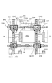
本実施形態の光電変換装置について、図1及び図3を用いて説明する。まず、図1(A)は図2(B)の平面図に対応した平面図である。
(First embodiment)
The photoelectric conversion apparatus of this embodiment is demonstrated using FIG.1 and FIG.3. First, FIG. 1A is a plan view corresponding to the plan view of FIG.
図1では、説明のため、光電変換素子の分離として機能しうる信号電荷に対して障壁となるP型の半導体領域が配置される領域を、図2(B)の平面レイアウトに重ねて示したものである。実際には、P型半導体領域は半導体基板内部に配置されており、図1では半導体基板の表面に各構成を投影した形状を示している。光電変換素子分離として機能しうるP型の半導体領域は、素子分離領域210にも配置されうる。そして、光電変換素子の分離として機能しうるP型の半導体領域は、第1の半導体領域110と、第3の半導体領域111と、第2の半導体領域1012とを含む。第1の半導体領域110は、第2の方向に沿って配置され、光電変換素子200aと第1の方向に隣に配置されている。つまり、第1の半導体領域110は、第1の光電変換素子と第2の光電変換素子との間に配置されている。第3の半導体領域111は、第1の方向に沿って配置され、光電変換素子200aと第2の方向に隣に配置されている。つまり、第3の半導体領域111は、第1の光電変換素子と第3の光電変換素子との間に配置されている。半導体基板の表面に配置を投影すると、第1の半導体領域110と第3の半導体領域111とは格子状に配されている。第2の半導体領域1012は、転送された信号電荷を読み出すためのトランジスタが配置された領域に配され、各トランジスタのゲート電極の下部に配されている。また、図1において、第2の半導体領域1012は、各トランジスタのチャネル部と、ソース領域と、ドレイン領域とに渡って配置されている。第1の半導体領域110及び第3の半導体領域111は、幅W1を有する。そして、第2の半導体領域1012は、トランジスタのチャネル部に対応して、チャネル部よりも幅広の幅W2を有し、チャネル部のチャネル長よりも長い長さL1あるいは長さL2を有する。このような構成によって、トランジスタのチャネル部に第1あるいは第3の半導体領域の端部がかかることがなく、トランジスタのチャネル部に一定の第2の半導体領域が配置される。よって、トランジスタの閾値ばらつきの発生が低減される。つまり、隣接する光電変換素子への信号電荷の流入を抑制しつつ、光電変換素子とトランジスタの特性とを維持することが可能となる。
In FIG. 1, for the sake of explanation, a region where a P-type semiconductor region serving as a barrier against signal charges that can function as a photoelectric conversion element separation is overlapped with the planar layout of FIG. Is. Actually, the P-type semiconductor region is disposed inside the semiconductor substrate, and FIG. 1 shows a shape in which each component is projected onto the surface of the semiconductor substrate. A P-type semiconductor region that can function as photoelectric conversion element isolation can also be disposed in the
なお、第2の半導体領域1012の幅W2は、対応するトランジスタのチャネル幅方向に平行であり、本実施形態では第1の方向に平行である。また、幅W2は、対応するトランジスタのチャネル幅より広い。また、第2の半導体領域1012は、長さL1及び長さL2を有しており、これは対応するトランジスタのチャネル長方向に平行であり、本実施形態では第2の方向に平行である。長さL1及び長さL2は任意であり、少なくとも対応するトランジスタのチャネル長よりも長ければよい。また、本実施例における転送された信号電荷を読み出すためのトランジスタとは、増幅トランジスタ、選択トランジスタ、リセットトランジスタである。
Note that the width W2 of the
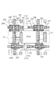
次に、図3を用いて、図1に対応する光電変換装置の断面模式図を説明する。図3(A)は図1のAB線に沿った断面模式図であり、図3(B)は図1のCD線に沿った断面模式図である。図3において図1と同様の構成には同一の符号を付し、説明を省略する。 Next, a schematic cross-sectional view of the photoelectric conversion device corresponding to FIG. 1 will be described with reference to FIG. 3A is a schematic cross-sectional view taken along line AB in FIG. 1, and FIG. 3B is a schematic cross-sectional view taken along line CD in FIG. In FIG. 3, the same components as those in FIG.
図3(A)及び図3(B)において、301はN型の半導体基板であり、302はP型の半導体領域である。半導体基板301は、半導体基板の上にエピタキシャル層を有する構成なども含むものとする。303は、転送トランジスタのゲート電極201aの下部に形成されるチャネル部を示し、304は図1の光電変換素子200aの電荷蓄積領域となるN型半導体領域である。305は選択トランジスタのゲート電極205の下部に形成されるチャネル部である。トランジスタのチャネル部とはトランジスタが動作している時にチャネルが形成されうる領域を示す。矢印Dは半導体基板301の深さ方向を示す。
In FIGS. 3A and 3B,
図3(A)及び図3(B)において、第1の半導体領域110は幅W1、深さ方向の長さD1を有し、第2の半導体領域1012は幅W2、深さ方向の長さD1を有する。図3(A)に示すように、トランジスタのソース領域あるいはドレイン領域を通るAB線断面においては、ドレイン領域207の下部に第1の半導体領域110が配置されている。一方、図3(B)に示すように、選択トランジスタのゲート電極205を通るCD線断面においては、選択トランジスタのゲート電極205の下部に第2の半導体領域1012が配置されている。第2の半導体領域1012は選択トランジスタのゲート電極205の下部に形成されるチャネル部305よりも幅が広く、またチャネル部305よりも下部に配置されている。このような構成によって、トランジスタの閾値ばらつきの発生が低減可能となる。
3A and 3B, the
チャネル部よりも半導体基板の深い位置に対してイオン注入を行う場合、イオンビームの特性により注入されるイオンの入射角がばらついてしまう場合がある。微細パターンを形成する際に斜めに入射されるイオンの一部は、高アスペクト比のフォトレジストの開口端を通過したり、フォトレジストの側壁で反射したりし、所定の注入エネルギーよりもエネルギーを損失した状態で半導体基板に進入する。このようなエネルギーを損失したイオンは所望の深さに達しない。 When ion implantation is performed at a position deeper in the semiconductor substrate than the channel portion, the incident angle of ions implanted may vary depending on the characteristics of the ion beam. Some of the ions incident obliquely when forming a fine pattern pass through the opening end of the photoresist with a high aspect ratio and are reflected by the sidewall of the photoresist, so that the energy is higher than the predetermined implantation energy. It enters the semiconductor substrate in a lost state. Ions that have lost such energy do not reach the desired depth.
ここで、もし、チャネル部の下部に配置されうるP型の半導体領域1012を、チャネル幅より細いパターンで形成すると、上述の理由により、所望の深さに達せず、チャネル部にP型の半導体領域が形成されてしまう場合が生じうる。このわずかに配置されるP型半導体領域によって、P型半導体領域302の濃度が向上し、N型のMOSトランジスタの閾値を上げてしまう場合がある。例えば、リセットMOSトランジスタの閾値が上昇すると、浮遊拡散部をリセットすることが困難となる。また、例えば増幅MOSトランジスタの閾値が上昇すると、信号出力時のダイナミックレンジが狭くなる。ここで、チャネル部の下部に配置される半導体領域1012はチャネル部よりも幅広くすることで、エネルギーを損失したイオンが注入されることを抑制することが可能となる。
Here, if the P-
なお、本実施形態の光電変換装置は、公知の半導体製造技術によって、例えば、図1に示す第1〜第3の半導体領域が配置される領域が開口されたフォトレジストマスクを用いて、イオン注入することによって形成可能である。また、第2の半導体領域と重複する領域を除く第1の半導体領域及び第3の半導体領域を形成し、第2の半導体領域を別の工程で形成してもよい。 Note that the photoelectric conversion device according to the present embodiment is ion-implanted by a known semiconductor manufacturing technique using, for example, a photoresist mask in which a region where the first to third semiconductor regions shown in FIG. 1 are arranged is opened. Can be formed. Alternatively, the first semiconductor region and the third semiconductor region excluding the region overlapping with the second semiconductor region may be formed, and the second semiconductor region may be formed in a separate step.
また、本実施形態において、隣接画素への信号電荷の混入量を一定にするため第1の半導体領域110と第3の半導体領域111とは同一の幅W1を有しているが、素子の配置によっては、異なる幅を有する場合もありうる。周囲の画素への信号電荷の漏れ量を一定にすることで、画像信号の補正処理を容易にすることが可能である。なお、第3の半導体領域111の幅は、隣接する浮遊拡散部204の寄生容量を増大させないように設定されると好ましい。
In this embodiment, the
また、第2の半導体領域は格子状に配置された第1の半導体領域と第3の半導体領域との交点に配置されることが望ましい。すなわち、転送された信号電荷を読み出すためのトランジスタが、格子状に配置された第1の半導体領域と第3の半導体領域との交点に配置されることが望ましい。このような配置によって、光電変換素子と他の素子との配置の対称性を向上させることが可能となる。また、このような配置によって、周囲の画素への信号電荷の漏れ量のばらつきを低減することが可能となる。 In addition, it is desirable that the second semiconductor region be disposed at the intersection of the first semiconductor region and the third semiconductor region which are disposed in a lattice shape. In other words, it is desirable that the transistor for reading the transferred signal charge is arranged at the intersection of the first semiconductor region and the third semiconductor region arranged in a lattice pattern. With such an arrangement, it is possible to improve the symmetry of the arrangement of the photoelectric conversion element and other elements. Further, such an arrangement makes it possible to reduce variations in the amount of signal charge leakage to surrounding pixels.
以上の構成によって、光電変換素子の感度を維持しつつ、トランジスタの性能低下を抑制することが可能な光電変換装置を提供することが可能となる。 With the above structure, it is possible to provide a photoelectric conversion device that can suppress deterioration in the performance of the transistor while maintaining the sensitivity of the photoelectric conversion element.
(第2の実施形態)
本実施形態の光電変換装置について図4を用いて説明する。図4は図3(B)に対応する断面模式図であり、図3(B)と同様の構成には、同一の符号を付し、説明を省略する。
(Second Embodiment)
The photoelectric conversion apparatus of this embodiment is demonstrated using FIG. FIG. 4 is a schematic cross-sectional view corresponding to FIG. 3B, and the same components as those in FIG.
本実施形態の光電変換装置は、第1の実施形態に比べて、光電変換素子の分離として機能しうる半導体領域が複数からなることが特徴である。つまり、図4において、第2の半導体領域1012の下部に、幅W2よりも狭く、第1の半導体領域と同一の幅W1を有する複数の第4の半導体領域401が配置されている。そして、第1の半導体領域110の下部に、幅W1を有する複数の第5の半導体領域402が配置されている。このような構成においても、トランジスタのチャネル部を覆って第2の半導体領域1012が配置されているため、トランジスタの性能を維持することが可能となる。
The photoelectric conversion device of this embodiment is characterized in that it includes a plurality of semiconductor regions that can function as separation of photoelectric conversion elements, as compared with the first embodiment. That is, in FIG. 4, a plurality of
また、同一の幅W1を有する第4の半導体領域401及び第5の半導体領域402が同一の深さに配置されているため、光電変換素子の深い位置で発生した信号電荷の漏れ量を均一にすることが容易となる。
Further, since the
なお、本実施形態において、第4の半導体領域401及び第5の半導体領域402は3つ配置されているが、これに限定されるものではない。また、第3の半導体領域1012は1つ配置されているが、複数が深さ方向に配置されていても良い。
In the present embodiment, three
(第3の実施形態)
本実施形態の光電変換装置について図5を用いて説明する。図5は図1に対応する断面模式図であり、図1と同様の構成には、同一の符号を付し、説明を省略する。
(Third embodiment)
The photoelectric conversion apparatus of this embodiment is demonstrated using FIG. FIG. 5 is a schematic cross-sectional view corresponding to FIG. 1, and the same components as those in FIG.
本実施形態の光電変換装置は、第1の実施形態に比べて、第2の半導体領域の長さが短いことが特徴である。つまり、図5において、第2の半導体領域7012は長さL3を有している。長さL3は、対応する図1の第2の半導体領域の長さL1及び長さL2よりも短い。長さL3は、トランジスタのチャネル長よりも長い。つまり、本実施形態の第2の半導体領域7012は、少なくともトランジスタのチャネル部を覆えればよく、図5に示すように、ソース領域あるいはドレイン領域のいずれかを覆っていなくてもよい。また、第1の実施形態においては第2の半導体領域は2つの長さを有していたが、本実施形態においては1つの長さL3のみである。このように長さを1つにすることで、平面レイアウトの対称性が向上し、信号電荷の漏れを均一にすることが可能となる。
The photoelectric conversion device of this embodiment is characterized in that the length of the second semiconductor region is shorter than that of the first embodiment. That is, in FIG. 5, the
なお、複数のトランジスタのうち、リセットトランジスタ、増幅トランジスタはその閾値の変化が読み出される信号に影響を与えるため、第2の半導体領域によってチャネル部が覆われていることが望ましい。選択トランジスタについては、信号に与える影響が小さいため、第2の半導体領域が配置されておらず、第1あるいは第3の半導体領域が配置されていてもよい。 Note that among the plurality of transistors, the reset transistor and the amplification transistor affect the signal from which the change in the threshold value is read. Therefore, the channel portion is preferably covered with the second semiconductor region. Since the selection transistor has a small influence on the signal, the second semiconductor region may not be disposed, and the first or third semiconductor region may be disposed.
(第4の実施形態)
本実施形態の光電変換装置について図6を用いて説明する。図6において、図1と同一の構成には同一の符号を付し、説明を省略する。
(Fourth embodiment)
The photoelectric conversion apparatus of this embodiment is demonstrated using FIG. In FIG. 6, the same components as those in FIG.
図6の本実施形態の光電変換装置は、幅W1の第1の半導体領域110と、幅W1の第3の半導体領域111と、幅W2の第2の半導体領域1012とを有している。このような構成によって、隣接する光電変換素子への信号電荷の流入を抑制しつつ、光電変換素子とトランジスタの特性とを維持することが可能としている。また、本実施形態の光電変換装置は、第1導電型の半導体領域110を配していない領域1112を有する。このような構成によって、光電変換素子200aから隣接する光電変換素子へ流入する信号電荷を調整することが可能となる。例えば、光電変換素子200aから第1の方向に隣接した光電変換素子へ流入する信号電荷が、光電変換素子200aから第2の方向に隣接した光電変換素子へ流入する信号電荷よりも少ない場合に、それらの信号電荷の量を均一にすることが可能となる。
The photoelectric conversion device of this embodiment in FIG. 6 includes a
また、領域1112を電源あるいはグランドといった固定電位が供給されるソース領域、ドレイン領域、あるいは任意の半導体領域(ウエルコンタクト等)の下部に設けることも可能である。このような構成にすれば、LOCOS等で発生した暗電流をソース領域、ドレイン領域、あるいは半導体領域に排出することも可能である。よって、光電変換素子に流入する暗電流を低減することが可能となる。
The
(第5の実施形態)
本発明の光電変換装置を撮像装置として撮像システムに適用した場合の一実施例について詳述する。撮像システムとして、デジタルスチルカメラやデジタルカムコーダーや監視カメラなどがあげられる。図7に、撮像システムの例としてデジタルスチルカメラに光電変換装置を適用した場合のブロック図を示す。
(Fifth embodiment)
An embodiment when the photoelectric conversion device of the present invention is applied to an imaging system as an imaging device will be described in detail. Examples of the imaging system include a digital still camera, a digital camcorder, and a surveillance camera. FIG. 7 shows a block diagram when a photoelectric conversion device is applied to a digital still camera as an example of an imaging system.
図7において、1はレンズの保護のためのバリア、2は被写体の光学像を撮像装置4(光電変換装置)に結像させるレンズ、3はレンズ2を通った光量を可変するための絞りである。6は撮像装置4より出力される撮像信号のアナログーディジタル変換を行うA/D変換器、7はA/D変換器6より出力された撮像データに各種の補正やデータを圧縮する信号処理部である。そして、図7において、8は撮像装置4、撮像信号処理回路5、A/D変換器6、信号処理部7に、各種タイミング信号を出力するタイミング発生部、9は各種演算とデジタルスチルカメラ全体を制御する全体制御・演算部である。10は画像データを一時的に記憶する為のメモリ部、11は記録媒体に記録または読み出しを行うためのインターフェース部、12は撮像データの記録または読み出しを行う為の半導体メモリ等の着脱可能な記録媒体である。そして、13は外部コンピュータ等と通信する為のインターフェース部である。ここで、タイミング信号などは外部から入力されてもよく、撮像システムは少なくとも撮像装置4と、撮像装置から出力された撮像信号を処理する信号処理部7とを有すればよい。また、タイミング発生部やA/D変換器が撮像装置と同一基板上に形成されていてもよい。以上のように、本発明の光電変換装置を撮像システムに適用することが可能である。本発明の光電変換装置を撮像システムに適用することにより、高品質な画像の取得が可能となる。
In FIG. 7, 1 is a barrier for protecting the lens, 2 is a lens for forming an optical image of a subject on an imaging device 4 (photoelectric conversion device), and 3 is a diaphragm for changing the amount of light passing through the lens 2. is there. Reference numeral 6 denotes an A / D converter that performs analog-to-digital conversion of an imaging signal output from the imaging apparatus 4, and 7 denotes a signal processing unit that compresses various corrections and data into the imaging data output from the A / D converter 6. It is. In FIG. 7, reference numeral 8 denotes an imaging device 4, an imaging
以上述べてきたように、本発明の構成によって、光電変換素子の感度を維持しつつ、トランジスタの性能低下を抑制することが可能な光電変換装置を提供することが可能となる。なお、各実施形態において第1、第3の半導体領域は格子状に配置されているが、素子の配置によるものであり、これに限定されない。また、第1〜第3の半導体領域などの半導体領域の深さ方向の長さについても適宜設定可能である。これらの構成および各実施形態は適宜組み合わせ可能である。 As described above, according to the configuration of the present invention, it is possible to provide a photoelectric conversion device that can suppress the deterioration of the performance of the transistor while maintaining the sensitivity of the photoelectric conversion element. In each embodiment, the first and third semiconductor regions are arranged in a lattice pattern, but this is due to the arrangement of the elements, and is not limited to this. Also, the length in the depth direction of the semiconductor region such as the first to third semiconductor regions can be set as appropriate. These configurations and the respective embodiments can be appropriately combined.
200a 光電変換素子
201a 転送MOSトランジスタのゲート電極
204a 浮遊拡散部
110 第1導電型の第1の半導体領域
111 第1導電型の第3の半導体領域
1012 第1導電型の第2の半導体領域
200a
Claims (9)
前記第1の光電変換素子に対して第1方向に沿って配置され、前記第1導電型の第2の電荷蓄積領域を含む第2の光電変換素子と、
前記第1の光電変換素子に対して前記第1方向と交わる第2方向に沿って配置され、前記第1導電型の第3の電荷蓄積領域を含む第3の光電変換素子と、
前記第1の光電変換素子にて生じた信号電荷を読み出すためのトランジスタと、が配置された前記第1導電型と反対導電型の第2導電型の半導体領域を含む半導体基板を有する光電変換装置において、
前記第1の電荷蓄積領域と前記第2の電荷蓄積領域との間の前記第2導電型の半導体領域にイオン注入によって形成され、前記半導体基板の深さ方向において前記トランジスタのチャネル部となる部分よりも深くに位置し、前記第2の方向に沿って配され、第1の幅を有する前記第2導電型の第1の半導体領域と、
前記第1の電荷蓄積領域と前記第2の電荷蓄積領域との間の前記第2導電型の半導体領域にイオン注入によって形成され、前記半導体基板の表面へ投影した時に、前記第2導電型の半導体領域の前記トランジスタが配された領域に配置され、前記半導体領域基板の深さ方向において前記トランジスタのチャネル部となる部分の下部に位置し、前記第1の幅よりも広く、前記トランジスタのチャネル部となる部分の幅よりも広い第2の幅を有する前記第2導電型の第2の半導体領域と、
前記第1の電荷蓄積領域と前記第3の電荷蓄積領域との間の前記第2導電型の半導体領域にイオン注入によって形成され、前記半導体基板の深さ方向において前記トランジスタのチャネル部となる部分よりも深くに位置し、前記第1の方向に沿って配され、前記第2の幅よりも狭い第3の幅を有する前記第2導電型の第3の半導体領域と、を有し、
前記半導体基板の表面へ投影した時に、前記第1の半導体領域と前記第3の半導体領域は、格子状に配置し、
前記半導体基板の表面へ投影した時に、前記第2の半導体領域は、前記第1の半導体領域が構成する前記格子の辺の一部である光電変換装置。 A first photoelectric conversion element including a first charge accumulation region of a first conductivity type ;
A second photoelectric conversion element disposed along the first direction with respect to the first photoelectric conversion element and including a second charge accumulation region of the first conductivity type;
A third photoelectric conversion element disposed along a second direction intersecting the first direction with respect to the first photoelectric conversion element and including a third charge accumulation region of the first conductivity type;
A photoelectric conversion device having a semiconductor substrate including a semiconductor region of a second conductivity type opposite to the first conductivity type in which a transistor for reading signal charges generated in the first photoelectric conversion element is disposed in,
A portion formed by ion implantation in the semiconductor region of the second conductivity type between the first charge storage region and the second charge storage region and serving as a channel portion of the transistor in the depth direction of the semiconductor substrate A first semiconductor region of the second conductivity type that is located deeper and is disposed along the second direction and having a first width ;
The second conductivity type is formed by ion implantation in the second conductivity type semiconductor region between the first charge accumulation region and the second charge accumulation region and projected onto the surface of the semiconductor substrate. The transistor is disposed in a region of the semiconductor region where the transistor is disposed, and is positioned below a portion that becomes a channel portion of the transistor in a depth direction of the semiconductor region substrate. a second semiconductor region of the second conductivity type having a wide second width greater than the width of the portion to be a part,
A portion formed by ion implantation in the semiconductor region of the second conductivity type between the first charge storage region and the third charge storage region and serving as a channel portion of the transistor in the depth direction of the semiconductor substrate located deeper than, arranged along the first direction, have a, a third semiconductor region of the second conductivity type having a narrow third width than said second width,
When projected onto the surface of the semiconductor substrate, the first semiconductor region and the third semiconductor region are arranged in a lattice pattern,
The photoelectric conversion device , wherein when projected onto the surface of the semiconductor substrate, the second semiconductor region is a part of a side of the lattice formed by the first semiconductor region .
前記第1の半導体領域は、前記第2方向に長辺を有し、
前記第3の半導体領域は、前記第1方向に長辺を有し、
前記第2の半導体領域は、前記格子の交差部に設けられている請求項1乃至5のいずれか1項に記載の光電変換装置。 When projected onto the surface of the semiconductor substrate,
The first semiconductor region has a long side in the second direction,
The third semiconductor region has a long side in the first direction,
Said second semiconductor region, the photoelectric conversion device according to any one of claims 1 to 5 are provided at intersections of the grid.
前記第2の半導体領域は、前記トランジスタのチャネル部となる部分の長さよりも長い長さを有する請求項1乃至7のいずれか1項に記載の光電変換装置。 The transistor is at least one of the reset transistor and an amplification transistor,
Said second semiconductor region, the photoelectric conversion device according to any one of claims 1 to 7 having a channel portion to become long length longer than the portion of the transistor.
前記光電変換装置から出力される信号を処理する信号処理回路と、を有する撮像システム。 The photoelectric conversion device according to any one of claims 1 to 8 ,
An image pickup system comprising: a signal processing circuit that processes a signal output from the photoelectric conversion device.
Priority Applications (5)
| Application Number | Priority Date | Filing Date | Title |
|---|---|---|---|
| JP2010185289A JP5539104B2 (en) | 2009-09-24 | 2010-08-20 | Photoelectric conversion device and imaging system using the same |
| US12/885,683 US8466401B2 (en) | 2009-09-24 | 2010-09-20 | Photoelectric conversion apparatus and imaging system using the photoelectric conversion apparatus |
| CN2010102884333A CN102034838B (en) | 2009-09-24 | 2010-09-21 | Photoelectric conversion apparatus and imaging system using the photoelectric conversion apparatus |
| CN201310059322.9A CN103151363B (en) | 2009-09-24 | 2010-09-21 | The imaging system of photoelectric conversion device and use photoelectric conversion device |
| US13/895,045 US8796609B2 (en) | 2009-09-24 | 2013-05-15 | Photoelectric conversion apparatus and imaging system using the photoelectric conversion apparatus |
Applications Claiming Priority (3)
| Application Number | Priority Date | Filing Date | Title |
|---|---|---|---|
| JP2009219218 | 2009-09-24 | ||
| JP2009219218 | 2009-09-24 | ||
| JP2010185289A JP5539104B2 (en) | 2009-09-24 | 2010-08-20 | Photoelectric conversion device and imaging system using the same |
Publications (3)
| Publication Number | Publication Date |
|---|---|
| JP2011091367A JP2011091367A (en) | 2011-05-06 |
| JP2011091367A5 JP2011091367A5 (en) | 2014-01-16 |
| JP5539104B2 true JP5539104B2 (en) | 2014-07-02 |
Family
ID=43755800
Family Applications (1)
| Application Number | Title | Priority Date | Filing Date |
|---|---|---|---|
| JP2010185289A Active JP5539104B2 (en) | 2009-09-24 | 2010-08-20 | Photoelectric conversion device and imaging system using the same |
Country Status (3)
| Country | Link |
|---|---|
| US (2) | US8466401B2 (en) |
| JP (1) | JP5539104B2 (en) |
| CN (2) | CN103151363B (en) |
Families Citing this family (18)
| Publication number | Priority date | Publication date | Assignee | Title |
|---|---|---|---|---|
| JP5558857B2 (en) | 2009-03-09 | 2014-07-23 | キヤノン株式会社 | Photoelectric conversion device and imaging system using the same |
| JP5539105B2 (en) | 2009-09-24 | 2014-07-02 | キヤノン株式会社 | Photoelectric conversion device and imaging system using the same |
| JP5679653B2 (en) * | 2009-12-09 | 2015-03-04 | キヤノン株式会社 | Photoelectric conversion device and imaging system using the same |
| JP5697371B2 (en) | 2010-07-07 | 2015-04-08 | キヤノン株式会社 | Solid-state imaging device and imaging system |
| JP5656484B2 (en) | 2010-07-07 | 2015-01-21 | キヤノン株式会社 | Solid-state imaging device and imaging system |
| JP5751766B2 (en) | 2010-07-07 | 2015-07-22 | キヤノン株式会社 | Solid-state imaging device and imaging system |
| JP5643555B2 (en) | 2010-07-07 | 2014-12-17 | キヤノン株式会社 | Solid-state imaging device and imaging system |
| JP5885401B2 (en) | 2010-07-07 | 2016-03-15 | キヤノン株式会社 | Solid-state imaging device and imaging system |
| JP5645513B2 (en) | 2010-07-07 | 2014-12-24 | キヤノン株式会社 | Solid-state imaging device and imaging system |
| JP6274788B2 (en) | 2013-08-28 | 2018-02-07 | キヤノン株式会社 | Imaging apparatus, imaging system, and driving method of imaging apparatus |
| JP2016058635A (en) * | 2014-09-11 | 2016-04-21 | ルネサスエレクトロニクス株式会社 | Semiconductor device manufacturing method |
| JP6562675B2 (en) * | 2015-03-26 | 2019-08-21 | キヤノン株式会社 | Photoelectric conversion device, imaging system, and driving method of photoelectric conversion device |
| JP6491519B2 (en) * | 2015-04-02 | 2019-03-27 | キヤノン株式会社 | Imaging device and imaging apparatus |
| JP6688165B2 (en) | 2016-06-10 | 2020-04-28 | キヤノン株式会社 | Imaging device and imaging system |
| JP7013119B2 (en) | 2016-07-21 | 2022-01-31 | キヤノン株式会社 | Solid-state image sensor, manufacturing method of solid-state image sensor, and image pickup system |
| CN108288439B (en) * | 2017-01-10 | 2020-06-30 | 陈扬证 | Display device |
| JP6904772B2 (en) | 2017-04-26 | 2021-07-21 | キヤノン株式会社 | Solid-state image sensor and its driving method |
| JP7245014B2 (en) | 2018-09-10 | 2023-03-23 | キヤノン株式会社 | Solid-state imaging device, imaging system, and driving method for solid-state imaging device |
Family Cites Families (26)
| Publication number | Priority date | Publication date | Assignee | Title |
|---|---|---|---|---|
| JP3530159B2 (en) | 2001-08-22 | 2004-05-24 | 松下電器産業株式会社 | Solid-state imaging device and method of manufacturing the same |
| JP3702854B2 (en) | 2002-03-06 | 2005-10-05 | ソニー株式会社 | Solid-state image sensor |
| JP2005268814A (en) * | 2002-06-27 | 2005-09-29 | Canon Inc | Solid state imaging device and camera system using the same |
| JP4208559B2 (en) | 2002-12-03 | 2009-01-14 | キヤノン株式会社 | Photoelectric conversion device |
| JP4514188B2 (en) | 2003-11-10 | 2010-07-28 | キヤノン株式会社 | Photoelectric conversion device and imaging device |
| JP4508619B2 (en) | 2003-12-03 | 2010-07-21 | キヤノン株式会社 | Method for manufacturing solid-state imaging device |
| JP3793202B2 (en) | 2004-02-02 | 2006-07-05 | キヤノン株式会社 | Solid-state imaging device |
| JP3890333B2 (en) | 2004-02-06 | 2007-03-07 | キヤノン株式会社 | Solid-state imaging device |
| JP4067054B2 (en) | 2004-02-13 | 2008-03-26 | キヤノン株式会社 | Solid-state imaging device and imaging system |
| JP4230406B2 (en) * | 2004-04-27 | 2009-02-25 | 富士通マイクロエレクトロニクス株式会社 | Solid-state imaging device |
| US7605415B2 (en) | 2004-06-07 | 2009-10-20 | Canon Kabushiki Kaisha | Image pickup device comprising photoelectric conversation unit, floating diffusion region and guard ring |
| JP5230058B2 (en) | 2004-06-07 | 2013-07-10 | キヤノン株式会社 | Solid-state imaging device and camera |
| JP4459064B2 (en) * | 2005-01-14 | 2010-04-28 | キヤノン株式会社 | Solid-state imaging device, control method thereof, and camera |
| JP2006319003A (en) * | 2005-05-10 | 2006-11-24 | Canon Inc | Image-capturing device |
| TWI310987B (en) | 2005-07-09 | 2009-06-11 | Samsung Electronics Co Ltd | Image sensors including active pixel sensor arrays |
| US7423302B2 (en) | 2005-11-21 | 2008-09-09 | Digital Imaging Systems Gmbh | Pinned photodiode (PPD) pixel with high shutter rejection ratio for snapshot operating CMOS sensor |
| JP4275150B2 (en) * | 2006-04-28 | 2009-06-10 | ヒロセ電機株式会社 | Device with modular jack |
| JP4928199B2 (en) | 2006-09-07 | 2012-05-09 | キヤノン株式会社 | Signal detection device, signal readout method of signal detection device, and imaging system using signal detection device |
| JP2008078302A (en) * | 2006-09-20 | 2008-04-03 | Canon Inc | Imaging apparatus and imaging system |
| JP2008084962A (en) | 2006-09-26 | 2008-04-10 | Toshiba Corp | Solid-state image sensing device and its manufacturing method |
| JP5142696B2 (en) | 2007-12-20 | 2013-02-13 | キヤノン株式会社 | Photoelectric conversion device and imaging system using photoelectric conversion device |
| JP5173493B2 (en) | 2008-02-29 | 2013-04-03 | キヤノン株式会社 | Imaging apparatus and imaging system |
| JP5178266B2 (en) | 2008-03-19 | 2013-04-10 | キヤノン株式会社 | Solid-state imaging device |
| JP5274166B2 (en) | 2008-09-10 | 2013-08-28 | キヤノン株式会社 | Photoelectric conversion device and imaging system |
| JP5539105B2 (en) | 2009-09-24 | 2014-07-02 | キヤノン株式会社 | Photoelectric conversion device and imaging system using the same |
| JP5679653B2 (en) | 2009-12-09 | 2015-03-04 | キヤノン株式会社 | Photoelectric conversion device and imaging system using the same |
-
2010
- 2010-08-20 JP JP2010185289A patent/JP5539104B2/en active Active
- 2010-09-20 US US12/885,683 patent/US8466401B2/en active Active
- 2010-09-21 CN CN201310059322.9A patent/CN103151363B/en active Active
- 2010-09-21 CN CN2010102884333A patent/CN102034838B/en active Active
-
2013
- 2013-05-15 US US13/895,045 patent/US8796609B2/en active Active
Also Published As
| Publication number | Publication date |
|---|---|
| JP2011091367A (en) | 2011-05-06 |
| CN103151363B (en) | 2015-10-21 |
| CN103151363A (en) | 2013-06-12 |
| US8796609B2 (en) | 2014-08-05 |
| US20110068253A1 (en) | 2011-03-24 |
| CN102034838B (en) | 2013-03-27 |
| CN102034838A (en) | 2011-04-27 |
| US8466401B2 (en) | 2013-06-18 |
| US20130248940A1 (en) | 2013-09-26 |
Similar Documents
| Publication | Publication Date | Title |
|---|---|---|
| JP5539104B2 (en) | Photoelectric conversion device and imaging system using the same | |
| US10103190B2 (en) | Imaging sensor having floating region of imaging device on one substrate electrically coupled to another floating region formed on a second substrate | |
| US9048155B2 (en) | Photoelectric conversion apparatus and imaging system using the same | |
| JP5335271B2 (en) | Photoelectric conversion device and imaging system using the same | |
| JP5679653B2 (en) | Photoelectric conversion device and imaging system using the same | |
| US8658956B2 (en) | Trench transfer gate for increased pixel fill factor | |
| US8803062B2 (en) | Photoelectric conversion device having a light-shielding film | |
| JP5723094B2 (en) | Solid-state imaging device and camera | |
| US10121816B2 (en) | Imaging device and method of manufacturing imaging device | |
| JP5539105B2 (en) | Photoelectric conversion device and imaging system using the same | |
| JP2008270299A (en) | Photoelectric converter and imaging device | |
| US11417691B2 (en) | Image sensor including dummy patterns positioned between adjacent transfer gates | |
| JP5036709B2 (en) | Pixels sharing an amplifier of a CMOS active pixel sensor | |
| JP6254048B2 (en) | Semiconductor device | |
| JP6029698B2 (en) | Photoelectric conversion device and imaging system using the same | |
| JP6420450B2 (en) | Semiconductor device | |
| JP5701344B2 (en) | Photoelectric conversion device and imaging system using the same | |
| TWI833304B (en) | Image sensor and method of fabricating the same |
Legal Events
| Date | Code | Title | Description |
|---|---|---|---|
| A521 | Request for written amendment filed |
Free format text: JAPANESE INTERMEDIATE CODE: A523 Effective date: 20130808 |
|
| A621 | Written request for application examination |
Free format text: JAPANESE INTERMEDIATE CODE: A621 Effective date: 20130808 |
|
| A521 | Request for written amendment filed |
Free format text: JAPANESE INTERMEDIATE CODE: A523 Effective date: 20131122 |
|
| A131 | Notification of reasons for refusal |
Free format text: JAPANESE INTERMEDIATE CODE: A131 Effective date: 20140107 |
|
| A521 | Request for written amendment filed |
Free format text: JAPANESE INTERMEDIATE CODE: A523 Effective date: 20140310 |
|
| TRDD | Decision of grant or rejection written | ||
| A01 | Written decision to grant a patent or to grant a registration (utility model) |
Free format text: JAPANESE INTERMEDIATE CODE: A01 Effective date: 20140401 |
|
| R151 | Written notification of patent or utility model registration |
Ref document number: 5539104 Country of ref document: JP Free format text: JAPANESE INTERMEDIATE CODE: R151 |
|
| A61 | First payment of annual fees (during grant procedure) |
Free format text: JAPANESE INTERMEDIATE CODE: A61 Effective date: 20140430 |