JP5538987B2 - Video camera device and heat dissipation structure thereof - Google Patents
Video camera device and heat dissipation structure thereof Download PDFInfo
- Publication number
- JP5538987B2 JP5538987B2 JP2010093793A JP2010093793A JP5538987B2 JP 5538987 B2 JP5538987 B2 JP 5538987B2 JP 2010093793 A JP2010093793 A JP 2010093793A JP 2010093793 A JP2010093793 A JP 2010093793A JP 5538987 B2 JP5538987 B2 JP 5538987B2
- Authority
- JP
- Japan
- Prior art keywords
- side plate
- camera
- wall portion
- heat
- heat radiating
- Prior art date
- Legal status (The legal status is an assumption and is not a legal conclusion. Google has not performed a legal analysis and makes no representation as to the accuracy of the status listed.)
- Active
Links
Images


Description
本発明は、放熱性の良い側板ドッカブル構造のビデオカメラ装置及びその放熱構造に関し、詳しくは、業務用のビデオカメラ装置であって、回路基板に実装した電子部品から発生する熱を自然放熱する空気流路を設けた側板ドッカブル構造のビデオカメラ装置及びその放熱構造に関する。 The present invention relates to a side camera dockable structure video camera device with good heat dissipation and a heat dissipation structure thereof, and more particularly to a commercial video camera device that naturally dissipates heat generated from electronic components mounted on a circuit board. The present invention relates to a video camera device having a side plate dockable structure provided with a flow path and a heat dissipation structure thereof.
従来、業務用のビデオカメラ装置には、カメラ本体とVTR部とが一体型のものや、カメラ本体とVTR部とが信号ケーブルで接続されるもの或いはカメラ本体とVTR部とが分離・合体自在に構成されたドッカブル型ビデオカメラ装置等とがある。ビデオカメラ装置では、一般にカメラ本体の上部に空冷用ファンが備えられ、空冷用ファンで筐体内部で発生する熱を強制的に外部に排出して空冷する方法が採られている。また、ビデオカメラ本体の側板に付設したヒートシンクを介して自然冷却するものや、空冷用ファンとヒートシンクとを組み合わせて放熱するのも等がある。 Conventional video camera devices for business use include a camera body and VTR unit integrated, a camera body and VTR unit connected by a signal cable, or a camera body and VTR unit that can be separated and combined. And a dockable video camera device configured as described above. In video camera devices, an air cooling fan is generally provided in the upper part of the camera body, and the air cooling fan forcibly exhausts the heat generated inside the housing to the outside and adopts a method of air cooling. In addition, there are those that naturally cool through a heat sink attached to the side plate of the video camera main body, and those that radiate heat by combining an air cooling fan and a heat sink.
空冷用ファンを用いて放熱するビデオカメラ装置では、上部に空冷用ファンが設けられることから発生した熱が上部から放出され、カメラ本体の上部に設けた把持部を握る撮影者の手に熱が排出されて不快感を与えて使い勝手が悪いといった問題点があった。図5(a)〜(c)を参照し、従来の放熱の問題を改善するビデオカメラ装置について説明する。図5(a)はドッカブル型ビデオカメラ装置を示し、カメラ本体1にはレンズ部2と上部に把持部3とが設けられ、その内部にCCD等による撮像素子4と、撮像素子4からの撮像信号を信号処理する回路基板5とが設けられ、回路基板5には発熱する電子部品6が実装され、電子部品6に伝熱シート7を接触させて設けられ、撮像素子4の背面側にはカメラ本体1内部と連通せず、外部と連通する放熱用空気流通路8が形成され、空冷用ファンで強制空冷することなく、電子部品6から発生した熱を伝熱シート7に伝達し放熱用空気流通路8を通してカメラ本体1から外部へと排出している。回路基板5は光軸に対して直交方向に配置され、放熱用空気流通路8は回路基板5に平行であり、光軸に対して直交方向に配置されている。カメラ本体1内部と連通してない放熱用空気流通路8には、図5(b)に示すように、上下方向に外部と連通する開口部9aがあり、また、図5(c)では、上方と側方とで外部と連通する開口部9a,9bがある(例えば、特許文献1参照)。
In a video camera device that dissipates heat using an air cooling fan, the heat generated by the air cooling fan provided at the top is released from the top, and the heat of the photographer's hand holding the grip provided at the top of the camera body is generated. There was a problem in that it was discharged and made uncomfortable and unusable. With reference to FIGS. 5A to 5C, a conventional video camera device that improves the problem of heat dissipation will be described. FIG. 5A shows a dockable type video camera device. The
しかしながら、従来のドッカブル型ビデオカメラ装置では、通常、カメラ本体と記録装置(VTR部)とを分離・合体自在とした構成であり、個々に放熱機構を設けて放熱する必要があり、そのためにカメラ本体内に収納する回路基板の収納容積が狭くなる傾向にあり、また、回路基板は光軸に対し直交方向に配置され、回路基板の枚数も増加する傾向にあり、コスト的にも高価になる傾向があった。従来のドッカブル型ビデオカメラ装置では、前後で分離・合体自在する構造であり、このような分離構造では、上記のような問題点が生じるため、分離・合体する位置等を変更し、放熱構造を互いに共通にした一体化構造として簡略化し、回路基板の枚数を減らして重量を低減することが望まれていた。 However, the conventional dockable video camera device usually has a configuration in which the camera body and the recording device (VTR unit) can be separated and combined, and it is necessary to dissipate heat by providing an individual heat dissipating mechanism. The storage capacity of the circuit board stored in the body tends to be narrowed, and the circuit board is arranged in a direction orthogonal to the optical axis, the number of circuit boards tends to increase, and the cost is high. There was a trend. The conventional dockable type video camera device has a structure that can be separated and combined at the front and rear, and such a separation structure causes the above-mentioned problems. It has been desired to simplify the integrated structure common to each other and reduce the weight by reducing the number of circuit boards.
さらに、特許文献1のビデオカメラ装置を参照し、その放熱構造について説明すると、回路基板が光軸に対して直交方向に配置され、回路基板のサイズがカメラ本体の横幅で制限され、回路基板が小型になり、種々の機能を得るためには回路基板の枚数を多くしなければならないといった欠点があった。即ち、回路基板の枚数が多くなれば、回路基板の枚数に応じて放熱用空気流通路を設けねばならないし、配線(ハーネス)が複雑になる欠点を有し、カメラ本体が大型化する要因になる欠点があり、また、放熱用空気流通路は電子部品が接触する側が熱伝導率の高い材質、例えば、マグネシウム、アルミニウム、銅等が使用され、反対側の素材が熱伝導率の低い材質、例えば、ABS、PC等の樹脂材料が使用されており、構造が複雑になるし、重量も重くなる欠点があり、コスト的にも高価になる欠点があった。
Furthermore, referring to the video camera device of
このような従来のドッカブル型ビデオカメラ装置では、カメラ本体に放熱構造が設けられるとともにVTR部(周辺機器)にも別途放熱構造を設ける必要があり、両方に設けられる放熱構造により重量が重くなり、コスト的にも高価になることから、新規なドッカブル構造であって、放熱構造を共有して簡素化し軽量化が計られるビデオカメラ装置が望まれていた。 In such a conventional dockable video camera device, it is necessary to provide a heat dissipation structure in the camera body and also to provide a separate heat dissipation structure in the VTR unit (peripheral device), and the heat dissipation structure provided in both increases the weight, Due to the high cost, a video camera device that has a novel dockable structure and that can be simplified and reduced in weight by sharing the heat dissipation structure has been desired.
本発明は、上記課題を達成したものであり、請求項1の発明は、レンズ部を装着した前面壁部の内側に撮像素子が設けられ、かつ背面壁部にスイッチ類を配置したカメラ本体よりなるビデオカメラ装置において、
前記カメラ本体が、前記前面壁部と前記背面壁部とを備えるカメラ枠体の両側面にそれぞれ第1と第2側板部を設けてなり、該第1側板部の内面側には回路基板を光軸方向に沿って垂設配置して第1の放熱板を設け、かつ該第2側板部側には該第2側板部と第2の放熱板との間にカメラアダプタ部及び又は記録装置が設けられ、前記ビデオカメラ装置が、前記第2側板部を前記カメラ枠体の一側面に結合する交換可能な側板ドッカブル構造であって、
前記第1と第2の放熱板間に外気が流入する空隙を形成し、平行に配置され、前記空隙を形成する前記第1と第2の放熱板に対応する前記カメラ本体の上面部及び下面部にそれぞれ通気孔を設け、前記空隙と該通気孔とを通して前記カメラ本体内に上下方向に外気が流れる放熱のための空気流路と、
前記第1側板部にはレンズ部側の正面壁部と背面壁部にそれぞれ貫通孔を形成し複数の前記回路基板間の空隙に空気が流入する光軸方向の空気流路から成る独立した2つの空気流路を形成し、
前記カメラ枠体には前記回路基板と前記第1の放熱板が配置された凹嵌部が設けられ、前記第2側板部の前記カメラアダプタ部のモジュール部と前記第2の放熱板が前記凹嵌部に嵌入すること
を特徴とするビデオカメラ装置である。
The present invention achieves the above-mentioned object, and the invention according to
The camera body is provided with first and second side plate portions on both side surfaces of a camera frame including the front wall portion and the rear wall portion, and a circuit board is provided on the inner surface side of the first side plate portion. A first heat radiating plate is provided so as to be suspended along the optical axis direction, and a camera adapter unit and / or a recording device is provided between the second side plate portion and the second heat radiating plate on the second side plate portion side. Provided, and the video camera device has a replaceable side plate dockable structure for coupling the second side plate portion to one side surface of the camera frame,
An upper surface and a lower surface of the camera body corresponding to the first and second heat radiating plates are formed in parallel to form a space between the first and second heat radiating plates. An air flow path for heat dissipation in which the outside air flows vertically in the camera body through the air gap and the air hole.
The first side plate portion is formed with through holes in the front wall portion and the back wall portion on the lens portion side, respectively, and includes two independent air flow paths in the optical axis direction through which air flows into gaps between the plurality of circuit boards. Form two air channels,
The camera frame is provided with a recessed fitting portion on which the circuit board and the first heat radiating plate are disposed, and the module portion of the camera adapter portion of the second side plate portion and the second heat radiating plate are recessed. A video camera device characterized by being fitted into a fitting portion .
本発明は、上記課題を達成したものであり、請求項1の発明は、レンズ部を装着した前面壁部の内側に撮像素子が設けられ、かつ背面壁部にスイッチ類を配置したカメラ本体よりなるビデオカメラ装置において、
前記カメラ本体が、前記前面壁部と前記背面壁部とを備えるカメラ枠体の両側面にそれぞれ第1と第2側板部を設けてなり、該第1側板部の内面側には回路基板を光軸方向に沿って垂設配置して第1の放熱板を設け、かつ該第2側板部側には該第2側板部と第2の放熱板との間にカメラアダプタ部及び又は記録装置が設けられ、前記ビデオカメラ装置が、前記第2側板部を前記カメラ枠体の一側面に結合する側板ドッカブル構造であって、前記第1と第2の放熱板間に外気が流入する空隙を形成したことを特徴とするビデオカメラ装置である。
The present invention achieves the above-mentioned object, and the invention according to
The camera body is provided with first and second side plate portions on both side surfaces of a camera frame including the front wall portion and the rear wall portion, and a circuit board is provided on the inner surface side of the first side plate portion. A first heat radiating plate is provided so as to be suspended along the optical axis direction, and a camera adapter unit and / or a recording device is provided between the second side plate portion and the second heat radiating plate on the second side plate portion side. And the video camera device has a side plate dockable structure in which the second side plate portion is coupled to one side surface of the camera frame body, and a gap through which outside air flows between the first and second heat radiating plates is provided. The video camera device is characterized by being formed.
また、請求項2の発明は、レンズ部を装着した前面壁部の内側に撮像素子が設けられ、かつ背面壁部にスイッチ類を配置したカメラ本体よりなるビデオカメラ装置の放熱構造であって、
前記カメラ本体が、前記前面壁部と前記背面壁部とを配置したカメラ枠体の両側面にそれぞれ第1と第2側板部が設けられてなり、該第2側板部の内側にはカメラアダプタ部及び又は記録装置が設けられ、前記カメラ枠体の一側面に該第2側板部を分離・合体可能とした側板ドッカブル構造であって、
前記第1側板部の内面側に複数の回路基板を光軸方向に沿って垂設配置して第1の放熱板が設けられ、かつ前記第2側板部の内面側にカメラアダプタ部及び又は記録装置を実装する箱部材が設けられ、該箱部材の外面に第2の放熱板が設けられ、
光軸方向に平行に配置された前記第1と第2の放熱板間に外気が流入する空隙を形成して自然空冷により放熱するものであり、
前記空隙を形成する前記第1と第2の放熱板に対応する前記カメラ本体の上面部及び下面部にそれぞれ通気孔を設け、前記空隙と該通気孔とを通して前記カメラ本体内に上下方向に外気が流入する放熱のための空気流路と、
前記第1側板部のレンズ部側の正面壁部及び背面壁部に貫通孔をそれぞれ設けて複数の前記回路基板間の空隙に外気が流入する光軸方向の空気流路と、
を形成して放熱することを特徴とするビデオカメラ装置の放熱構造である。
The invention of
The camera body is provided with first and second side plate portions on both side surfaces of a camera frame in which the front wall portion and the rear wall portion are arranged, and a camera adapter is provided inside the second side plate portion. A side plate dockable structure in which a second side plate portion can be separated and combined with one side surface of the camera frame body,
A plurality of circuit boards are arranged vertically along the optical axis direction on the inner surface side of the first side plate portion, a first heat radiating plate is provided, and a camera adapter portion and / or recording are provided on the inner surface side of the second side plate portion. A box member for mounting the device is provided, and a second heat sink is provided on the outer surface of the box member;
Between the first and second heat dissipating plates arranged in parallel to the optical axis direction to form a gap into which outside air flows to dissipate heat by natural air cooling ,
Ventilation holes are provided in the upper surface portion and the lower surface portion of the camera body corresponding to the first and second heat radiating plates forming the gap, and the outside air is vertically moved into the camera body through the gap and the ventilation hole. An air flow path for heat dissipation into which
An air flow path in the optical axis direction in which outside air flows into the gaps between the plurality of circuit boards by providing through holes in the front wall portion and the back wall portion on the lens portion side of the first side plate portion, respectively.
The heat dissipation structure of the video camera device is characterized in that the heat is dissipated by forming a film.
請求項1の発明では、請求項1の発明は、レンズ部を装着した前面壁部の内側に撮像素子が設けられ、かつ背面壁部にスイッチ類を配置したカメラ本体よりなるビデオカメラ装置において、前記カメラ本体が、前記前面壁部と前記背面壁部とを備えるカメラ枠体の両側面にそれぞれ第1と第2側板部を設けてなり、該第1側板部の内面側には回路基板を光軸方向に沿って垂設配置して第1の放熱板を設け、かつ該第2側板部側には該第2側板部と第2の放熱板との間にカメラアダプタ部及び又は記録装置が設けられ、前記ビデオカメラ装置が、前記第2側板部を前記カメラ枠体の一側面に結合する交換可能な側板ドッカブル構造であって、前記第1と第2の放熱板間に外気が流入する空隙を形成し、平行に配置され、前記空隙を形成する前記第1と第2の放熱板に対応する前記カメラ本体の上面部及び下面部にそれぞれ通気孔を設け、前記空隙と該通気孔とを通して前記カメラ本体内に上下方向に外気が流れる放熱のための空気流路と、前記第1側板部にはレンズ部側の正面壁部と背面壁部にそれぞれ貫通孔を形成し複数の前記回路基板間の空隙に空気が流入する光軸方向の空気流路から成る独立した2つの空気流路を形成し、前記カメラ枠体には前記回路基板と前記第1の放熱板が配置された凹嵌部が設けられ、前記第2側板部の前記カメラアダプタ部のモジュール部と前記第2の放熱板が前記凹嵌部に嵌入することを特徴とするビデオカメラ装置であるので、第2側板部をドッカブル方式でドッキングすることが可能であり、回路基板を収納するための光軸方向に沿った長手方向の空間を形成することができ、この空間内に、第1と第2側板部間に複数枚の回路基板を光軸方向に沿って平行に垂設することができるし、第1側板部側の回路基板の第1放熱板による放熱構造と、カメラアダプタ部及び又は記録装置を設けた第2側板部側の第2放熱板による放熱構造とを共有した一体の放熱構造とし、自然放熱による放熱構造を簡略化して軽量化が計られ、コスト的にも安価な側板ドッカブル構造のビデオカメラ装置を提供できる利点がある。
また、回路基板を従来より大型にできるし、回路基板の第1の放熱板による放熱構造とカメラアダプタ部側の放熱構造とを共有して一体とすることで軽量化に寄与し、コスト的にも安価なものとなる利点がある。
また、第2側板部に設けたカメラアダプタ部のモジュール部等に設けた第2の放熱板を凹嵌部に嵌入することによって、第1の放熱板に対して第2の放熱板を平行に配置することができ、これらの部材の空隙による空気流路が容易に形成できる利点がある。
また、空気流路はカメラ本体内にも通じており、カメラ本体内に収納した回路基板間の空隙にも上下方向及び光軸方向から空気が流入して流路が形成され、効率良く自然放熱することができる。
In the invention of
In addition, the circuit board can be made larger than before, and the heat dissipation structure by the first heat dissipation plate of the circuit board and the heat dissipation structure on the camera adapter part side are shared and integrated, contributing to weight reduction and cost. Also has the advantage of being inexpensive.
Further, by inserting the second heat radiating plate provided in the module portion of the camera adapter portion provided in the second side plate portion into the recessed fitting portion, the second heat radiating plate is made parallel to the first heat radiating plate. There is an advantage that an air flow path can be easily formed by the gap between these members.
In addition, the air flow path leads to the inside of the camera body, and air flows into the gap between the circuit boards housed in the camera body from the vertical direction and the optical axis direction to form a flow path. can do.
また、請求項2の発明では、レンズ部を装着した前面壁部の内側に撮像素子が設けられ、かつ背面壁部にスイッチ類を配置したカメラ本体よりなるビデオカメラ装置の放熱構造であって、前記カメラ本体が、前記前面壁部と前記背面壁部とを配置したカメラ枠体の両側面にそれぞれ第1と第2側板部が設けられてなり、該第2側板部の内側にはカメラアダプタ部及び又は記録装置が設けられ、前記カメラ枠体の一側面に該第2側板部を分離・合体可能とした側板ドッカブル構造であって、前記第1側板部の内面側に複数の回路基板を光軸方向に沿って垂設配置して第1の放熱板が設けられ、かつ前記第2側板部の内面側にカメラアダプタ部及び又は記録装置を実装する箱部材が設けられ、該箱部材の外面に第2の放熱板が設けられ、光軸方向に平行に配置された前記第1と第2の放熱板間に外気が流入する空隙を形成して自然空冷により放熱するものであり、前記空隙を形成する前記第1と第2の放熱板に対応する前記カメラ本体の上面部及び下面部にそれぞれ通気孔を設け、前記空隙と該通気孔とを通して前記カメラ本体内に上下方向に外気が流入する放熱のための空気流路と、前記第1側板部のレンズ部側の正面壁部及び背面壁部に貫通孔をそれぞれ設けて複数の前記回路基板間の空隙に外気が流入する光軸方向の空気流路と、を形成して放熱することを特徴とするビデオカメラ装置の放熱構造であるので、第2側板部がドッカブル方式でドッキングする側板ドッカブル構造のビデオカメラ装置であり、ビデオカメラ装置内部に回路基板を収納するための長手方向の比較的大きな空間が形成され、この空間内に、複数枚の回路基板を光軸方向に沿って平行に垂設して第1の放熱板を設けて第1の放熱構造を形成し、第2側板部にカメラアダプタ部及び又は記録装置を設けた第2の放熱板による第2の放熱構造を形成することによって、第1と第2の放熱板を平行に配置し対面させて一体の放熱構造とし、簡略化された自然放熱による放熱構造を形成することができ、軽量化が可能であるとともに、配線を簡素化でき、コスト的にも安価なビデオカメラ装置の放熱構造が提供できる利点がある。
また、第1側板部側に設けた第1の放熱板と、第2側板部側に設けた第2の放熱板間に形成された空隙とビデオカメラ枠体の上面壁部及び下面壁部に設けた通気孔とにより、上下方向に空気が流れる空気流路が形成されて効率良く自然放熱することができる利点がある。
また、カメラ本体内に上下方向の空気の流れに加えて光軸方向の空気の流れを形成することができ、自然放熱による一層効率の良い放熱構造を提供できる利点がある。
The invention of
Also, the first heat sink provided on the first side plate portion side, the gap formed between the second heat sink provided on the second side plate portion side, the upper surface wall portion and the lower surface wall portion of the video camera frame body The vent hole provided has an advantage that an air flow path through which air flows in the vertical direction is formed, and natural heat dissipation can be efficiently performed.
Further, in addition to the air flow in the vertical direction in the camera body, an air flow in the optical axis direction can be formed, and there is an advantage that a more efficient heat dissipation structure by natural heat dissipation can be provided.
また、請求項6の発明では、請求項5に記載のビデオカメラ装置の放熱構造であって、
平行に配置され、前記空隙を形成する前記第1と第2の放熱板に対応する前記カメラ本体の上面部及び下面部にそれぞれ通気孔を設け、前記空隙と該通気孔とを通して前記カメラ本体内に上下方向に外気が流入する放熱のための空気流路を形成したことを特徴とするビデオカメラ装置の放熱構造であるので、第1側板部側に設けた第1の放熱板と、第2側板部側に設けた第2の放熱板間に形成された空隙とビデオカメラ枠体の上面壁部及び下面壁部に設けた通気孔とにより、上下方向に空気が流れる空気流路が形成されて効率良く自然放熱することができる利点がある。また、映像処理回路側の回路基板とカメラアダプタ部側の放熱構造を共有することができるので、ビデオカメラ装置の軽量化に寄与し、コスト的にも利点がある。
The invention of
A vent hole is provided in each of the upper surface portion and the lower surface portion of the camera body corresponding to the first and second heat radiating plates which are arranged in parallel and form the gap, and the camera body passes through the gap and the vent hole. Since the heat dissipation structure of the video camera device is characterized in that an air flow path for heat dissipation from which outside air flows in the vertical direction is formed, a first heat dissipation plate provided on the first side plate portion side, An air flow path through which air flows in the vertical direction is formed by the gap formed between the second heat radiating plates provided on the side plate portion side and the vent holes provided in the upper surface wall portion and the lower surface wall portion of the video camera frame. There is an advantage that natural heat can be efficiently dissipated. In addition, the circuit board on the video processing circuit side and the heat dissipation structure on the camera adapter unit side can be shared, which contributes to weight reduction of the video camera device and is advantageous in terms of cost.
また、請求項7の発明では、前記第1側板部のレンズ部側の正面壁部及び背面壁部に貫通孔をそれぞれ形成して光軸方向の空気流路を形成したことを特徴とする請求項6に記載のビデオカメラ装置の放熱構造であるので、カメラ本体内に上下方向の空気の流れに加えて光軸方向の空気の流れを形成することができ、自然放熱による一層効率の良い放熱構造を提供できる利点がある。
According to a seventh aspect of the invention, an air flow path in the optical axis direction is formed by forming through holes in the front wall portion and the rear wall portion of the first side plate portion on the lens portion side. Since it is a heat dissipation structure of the video camera apparatus of item |
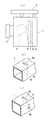
以下、本発明のビデオカメラ装置及びその放熱構造の実施例について図面を参照し説明する。なお、図1は本実施例の斜視図、図2は本実施例のビデオカメラ装置の側板部を分離した状態を示す斜視図、図3は本実施例の第1側板部を外した状態の分解斜視図と要部拡大図、図4は本実施例の放熱のための空気流路を示す説明図である。 Embodiments of a video camera device and a heat dissipation structure thereof according to the present invention will be described below with reference to the drawings. 1 is a perspective view of the present embodiment, FIG. 2 is a perspective view showing a state in which the side plate portion of the video camera apparatus of the present embodiment is separated, and FIG. 3 is a state in which the first side plate portion of the present embodiment is removed. FIG. 4 is an explanatory view showing an air flow path for heat dissipation in this embodiment.
先ず、図1,図2を参照しビデオカメラ装置の実施例について説明する。ビデオカメラ装置10にはカメラ本体11と、カメラ本体11の前面壁に装着されるレンズ部12とが備えられ、レンズ部12にはズームスイッチが設けられたグリップ部12aが設けられ、カメラ本体11の上面に把持部13が設けられている。カメラ本体11は上面壁部14a、前面壁部14b、背面壁部14c及び下面壁部14dからなるカメラ枠体14と、カメラ枠体14の両側面を覆う第1側板部15aと第2側板部15bとからなる。カメラ枠体14の前部分に設けた区画部141 には撮像素子(図示なし)と撮像素子からの映像信号を受ける回路基板とが配置され、背面部の区画部142 にはスイッチ類やコネクタ類(図示なし)が背面壁部14cに実装され、それらの配線が収納される。なお、詳しくは、把持部13はカメラ枠体14の上面壁部14aに設けられ、レンズ部12は前面壁部14bに装着される。なお、カメラ本体11の上面壁部は把持部13の一部とともに着脱可能な蓋状部材で構成されており、本実施例ではその説明を省略する。
First, an embodiment of a video camera device will be described with reference to FIGS. The
本実施例のビデオカメラ装置11は、カメラ枠体14の両側面にそれぞれ第1と第2側板部15a,15bを設けてカメラ本体11を形成し、第2側板部15bの内側に周辺機器であるカメラアダプタ部及び又は記録装置が設けられ、カメラ枠体14の一側面に第2側板部15bを結合してなる側板ドッカブル構造である。カメラ枠体14には、区画部141 ,142 間に凹嵌部143 が形成され、凹嵌部143 の底部には、第1側板部15aの内面側に設けた放熱板16が配置され、放熱板16は光軸方向に沿って平行であり、縦方向に垂設されている。第1側板部15aと放熱板16との間に平行に複数枚の回路基板20(図3参照)が光軸方向に沿って垂設される。なお、図3では放熱板16は図示を省略している。回路基板20に実装した発熱する電子部品を放熱板16に接触させて回路基板20を垂設して放熱板16を通し効率良く放熱する。また、複数の回路基板20との間には空隙が形成され、放熱を良好なものとしている。
In the
第2側板部15bは、その内面側にカメラアダプタ部18のモジュール部18aが収納される箱部材19が設けられ、箱部材19の底面部の表面側に放熱板19aが設けられ、第2側板部15bの表面側にはカメラアダプタ部18のコネクタ18bが設けられる。カメラアダプタ部18はモジュール部18aとコネクタ18bとからなり、カメラアダプタ部18は、トライアックスアダプタ(TA)又はファイバーアダプタ(FA)のモジュール部であり、コネクタ18bはトライアックスケーブル又はファイバーケーブルが接続される接続部である。ビデオカメラ装置11は、トライアックスケーブル又はファイバーケーブルによりカメラコントロールユニット(CCU)と接続される。
The second
さらに、本実施例の放熱構造について説明する。本実施例では、ビデオカメラ装置が側板ドッカブル構造であり、即ち、カメラ枠体14に設けた凹嵌部143 に第2側板部15bの箱部材19を嵌入して第2側板部15bをカメラ枠体14側面にネジで緊縮することによって、第2側板部15bをカメラ枠体14に装着することができる。本実施例のビデオカメラ装置は第2側板部15bをドッカブル方式でドッキングすることが可能な側板ドッカブル構造であり、スタジオシステムに応じてトライアックスアダプタ又はファイバーアダプタであるカメラアダプタ部18を形成した第2側板部15bを容易に交換できるとともに、第2側板部15bをドッキングすることにより、カメラ枠体14に設けた凹嵌部143 に第2側板部15bの箱部材19が嵌入し、放熱板19aが第1側板部15aの内面側に設けた放熱板16に平行に配置され、第1と第2の放熱板16,19a間に外気が流入する空隙が形成される。
Furthermore, the heat dissipation structure of the present embodiment will be described. In this embodiment, a video camera device is the side plate dockable structure, i.e., the camera and the second
また、カメラ本体11の上面部及び下面部には、カメラ本体11内に配置した第1と第2の放熱板16,19aにより形成される空隙に対応する位置にそれぞれ通気孔17a,17bが形成される。第1と第2の放熱板16,19a間に外気が流入する空隙と、通気孔17a,17bとを通して、カメラ本体14内に上下方向に外気が流入する放熱のための空気流路A(図4参照)が形成され、空気流路Aによる放熱構造がビデオカメラ装置に形成される。
In addition,
この放熱構造では、第1側板部15aの内側に設けた第1の放熱板16と、第2側板部15bの内側に設けた箱部材19の底板表面に設けられた第2の放熱板19aとが光軸方向に沿って互い平行に配置されて空隙が形成され、回路基板20の中で最も発熱する電子部品が第1の放熱板16に接触するように配置されて熱を伝導し、かつ箱部材19内にはカメラアダプタ部18のモジュール部18aが実装されて発生する熱が第2の放熱板19aを介して伝導して放熱され、これら第1の放熱板16と第2の放熱板19aとの空隙によって空気の流れが発生し易く、カメラ本体11の上面部及び下面部に設けた通気孔17a,17bにより空気流路Aが形成され、外気の流入が容易な構造とし、自然放熱が容易となっている。かつ、第1側板部15aと第1の放熱板16間に平行に実装される複数の回路基板20間にも空隙が形成されて空気の流れが発生し易い放熱構造としている。また、通気孔17a,17bは、第1と第2の放熱板16,19aとの空隙の上方及び下方に形成されており、たとえ、雨水が通気孔17a,17bからカメラ本体11内に侵入したとしても直接電子部品側に流れ込むことが抑制されている。
In this heat dissipation structure, a first
また、箱部材19内に実装されるモジュール部18aは、トライアックスアダプタ(TA)又はファイバーアダプタ(FA)である。なお、箱部材19には映像信号を記録するハードディスクやフラシュメモリ等の記録装置(図示なし)を装着するようにしてもよいし、カメラアダプタ部18を設けることなく、記録装置のみを装着するようにしてもよい(図示なし)。箱部材19内に記録装置が装着される場合も同様にその発熱面を放熱板19aに接触させる。
Moreover, the
一方、回路基板20(図3参照)は、光軸方向に配置されるので、回路基板の面積を、従来のカメラ部とVTR部とを分離・合体するドッカブル型ビデオカメラ装置に使用される回路基板では、カメラ本体の幅方向に回路基板が配置されるので回路基板を小型にして枚数を多くする必要があったが、側板ドッカブル構造のビデオカメラ装置であるので、光軸方向、即ちカメラ本体の長手方向に回路基板を配置することができ、回路基板の面積を従来より拡大することができる。その結果、回路基板の枚数を少なくすることができるし、回路基板間を接続する配線(ハーネスケーブル)を少なくすることができ、コスト的にも安価になり、軽量化にも寄与する。 On the other hand, since the circuit board 20 (see FIG. 3) is arranged in the optical axis direction, the circuit used in a dockable video camera apparatus that separates and combines the conventional camera unit and VTR unit with respect to the area of the circuit board. In the board, the circuit board is arranged in the width direction of the camera body, so it was necessary to reduce the size of the circuit board and increase the number of sheets. However, since the video camera device has a side-board dockable structure, The circuit board can be arranged in the longitudinal direction of the circuit board, and the area of the circuit board can be increased as compared with the conventional case. As a result, the number of circuit boards can be reduced, the number of wirings (harness cables) for connecting the circuit boards can be reduced, the cost is reduced, and the weight is reduced.
続いて、図3を参照し、本発明の他の実施例について説明する。図3の実施例は、上記実施例と同様の構造であり、第1側板部15aが相違している。即ち、第1側板部15aのレンズ部12側の正面壁部151 及び背面壁部152 に通気孔21,22がそれぞれ形成され、これらの通気孔21,22によって、カメラ本体11内に収納された複数の回路基板20間の空隙に空気が流入する光軸方向の空気流路Bが形成される。また、上記実施例では空気流路Aが形成されるので、本実施例では、上下方向の空気流路Aと光軸方向の空気流路Bとによって、回路基板20とモジュール部18a(図2参照)とを放熱板16,19aで効率良く放熱することができる。無論、第2側板部15bの正面壁部151 及び背面壁部152 に通気孔に設けても良い。
Next, another embodiment of the present invention will be described with reference to FIG. The embodiment of FIG. 3 has the same structure as the above embodiment, and the first
本発明の活用例としては、スタジオ等のシステムに応じてカメラアダプタ部を容易に交換して撮影が可能なビデオカメラ装置として利用することができる。 As an application example of the present invention, the present invention can be used as a video camera apparatus capable of easily exchanging a camera adapter unit according to a system such as a studio.
10 ビデオカメラ装置
11 カメラ本体
12 レンズ部
12a グリップ部
13 把持部
14 カメラ枠体
14a 上面壁部
14b 前面壁部
14c 背面壁部
14d 下面壁部
141 ,142 区画部
143 凹嵌部
15a 第1側板部
15b 第2側板部
151 正面壁部
152 背面壁部
16 放熱板
17a,17b 通気孔
18 カメラアダプタ部
18a モジュール部
18b コネクタ
19 箱部材
19a 放熱板
20 回路基板
A,B 空気流路
10
Claims (2)
前記カメラ本体が、前記前面壁部と前記背面壁部とを備えるカメラ枠体の両側面にそれぞれ第1と第2側板部を設けてなり、該第1側板部の内面側には回路基板を光軸方向に沿って垂設配置して第1の放熱板を設け、かつ該第2側板部側には該第2側板部と第2の放熱板との間にカメラアダプタ部及び又は記録装置が設けられ、前記ビデオカメラ装置が、前記第2側板部を前記カメラ枠体の一側面に結合する交換可能な側板ドッカブル構造であって、
前記第1と第2の放熱板間に外気が流入する空隙を形成し、平行に配置され、前記空隙を形成する前記第1と第2の放熱板に対応する前記カメラ本体の上面部及び下面部にそれぞれ通気孔を設け、前記空隙と該通気孔とを通して前記カメラ本体内に上下方向に外気が流れる放熱のための空気流路と、
前記第1側板部にはレンズ部側の正面壁部と背面壁部にそれぞれ貫通孔を形成し複数の前記回路基板間の空隙に空気が流入する光軸方向の空気流路から成る独立した2つの空気流路を形成し、
前記カメラ枠体には前記回路基板と前記第1の放熱板が配置された凹嵌部が設けられ、前記第2側板部の前記カメラアダプタ部のモジュール部と前記第2の放熱板が前記凹嵌部に嵌入すること
を特徴とするビデオカメラ装置。 In a video camera device comprising a camera body in which an imaging element is provided inside a front wall portion to which a lens portion is attached, and switches are arranged on a rear wall portion,
The camera body is provided with first and second side plate portions on both side surfaces of a camera frame including the front wall portion and the rear wall portion, and a circuit board is provided on the inner surface side of the first side plate portion. A first heat radiating plate is provided so as to be suspended along the optical axis direction, and a camera adapter unit and / or a recording device is provided between the second side plate portion and the second heat radiating plate on the second side plate portion side. Provided, and the video camera device has a replaceable side plate dockable structure for coupling the second side plate portion to one side surface of the camera frame,
An upper surface and a lower surface of the camera body corresponding to the first and second heat radiating plates are formed in parallel to form a space between the first and second heat radiating plates. An air flow path for heat dissipation in which the outside air flows vertically in the camera body through the air gap and the air hole.
The first side plate portion is formed with through holes in the front wall portion and the back wall portion on the lens portion side, respectively, and includes two independent air flow paths in the optical axis direction through which air flows into gaps between the plurality of circuit boards. Form two air channels,
The camera frame is provided with a recessed fitting portion on which the circuit board and the first heat radiating plate are disposed, and the module portion of the camera adapter portion of the second side plate portion and the second heat radiating plate are recessed. A video camera device characterized by being fitted into a fitting portion .
前記カメラ本体が、前記前面壁部と前記背面壁部とを配置したカメラ枠体の両側面にそれぞれ第1と第2側板部が設けられてなり、該第2側板部の内側にはカメラアダプタ部及び又は記録装置が設けられ、前記カメラ枠体の一側面に該第2側板部を分離・合体可能とした側板ドッカブル構造であって、
前記第1側板部の内面側に複数の回路基板を光軸方向に沿って垂設配置して第1の放熱板が設けられ、かつ前記第2側板部の内面側にカメラアダプタ部及び又は記録装置を実装する箱部材が設けられ、該箱部材の外面に第2の放熱板が設けられ、
光軸方向に平行に配置された前記第1と第2の放熱板間に外気が流入する空隙を形成して自然空冷により放熱するものであり、
前記空隙を形成する前記第1と第2の放熱板に対応する前記カメラ本体の上面部及び下面部にそれぞれ通気孔を設け、前記空隙と該通気孔とを通して前記カメラ本体内に上下方向に外気が流入する放熱のための空気流路と、
前記第1側板部のレンズ部側の正面壁部及び背面壁部に貫通孔をそれぞれ設けて複数の前記回路基板間の空隙に外気が流入する光軸方向の空気流路と、
を形成して放熱することを特徴とするビデオカメラ装置の放熱構造。 A heat dissipation structure of a video camera device comprising a camera body in which an imaging element is provided inside a front wall portion to which a lens portion is attached, and switches are arranged on a rear wall portion,
The camera body is provided with first and second side plate portions on both side surfaces of a camera frame in which the front wall portion and the rear wall portion are arranged, and a camera adapter is provided inside the second side plate portion. A side plate dockable structure in which a second side plate portion can be separated and combined with one side surface of the camera frame body,
A plurality of circuit boards are arranged vertically along the optical axis direction on the inner surface side of the first side plate portion, a first heat radiating plate is provided, and a camera adapter portion and / or recording are provided on the inner surface side of the second side plate portion. A box member for mounting the device is provided, and a second heat sink is provided on the outer surface of the box member;
Between the first and second heat dissipating plates arranged in parallel to the optical axis direction to form a gap into which outside air flows to dissipate heat by natural air cooling ,
Ventilation holes are provided in the upper surface portion and the lower surface portion of the camera body corresponding to the first and second heat radiating plates forming the gap, and the outside air is vertically moved into the camera body through the gap and the ventilation hole. An air flow path for heat dissipation into which
An air flow path in the optical axis direction in which outside air flows into the gaps between the plurality of circuit boards by providing through holes in the front wall portion and the back wall portion on the lens portion side of the first side plate portion, respectively.
A heat dissipating structure for a video camera device, wherein the heat dissipating is formed .
Priority Applications (1)
| Application Number | Priority Date | Filing Date | Title |
|---|---|---|---|
| JP2010093793A JP5538987B2 (en) | 2010-04-15 | 2010-04-15 | Video camera device and heat dissipation structure thereof |
Applications Claiming Priority (1)
| Application Number | Priority Date | Filing Date | Title |
|---|---|---|---|
| JP2010093793A JP5538987B2 (en) | 2010-04-15 | 2010-04-15 | Video camera device and heat dissipation structure thereof |
Publications (3)
| Publication Number | Publication Date |
|---|---|
| JP2011228768A JP2011228768A (en) | 2011-11-10 |
| JP2011228768A5 JP2011228768A5 (en) | 2013-03-14 |
| JP5538987B2 true JP5538987B2 (en) | 2014-07-02 |
Family
ID=45043656
Family Applications (1)
| Application Number | Title | Priority Date | Filing Date |
|---|---|---|---|
| JP2010093793A Active JP5538987B2 (en) | 2010-04-15 | 2010-04-15 | Video camera device and heat dissipation structure thereof |
Country Status (1)
| Country | Link |
|---|---|
| JP (1) | JP5538987B2 (en) |
Families Citing this family (3)
| Publication number | Priority date | Publication date | Assignee | Title |
|---|---|---|---|---|
| CN106060345B (en) | 2015-04-10 | 2021-06-25 | 黑魔法设计私人有限公司 | Digital video camera |
| CN107566697B (en) * | 2017-08-28 | 2019-09-17 | 浙江大华技术股份有限公司 | A kind of monitoring device with temperature detecting unit |
| CN113315893B (en) * | 2021-05-17 | 2023-10-27 | 杭州海康威视数字技术股份有限公司 | Video camera and video apparatus |
Family Cites Families (2)
| Publication number | Priority date | Publication date | Assignee | Title |
|---|---|---|---|---|
| JP2005063534A (en) * | 2003-08-08 | 2005-03-10 | Sony Corp | Disk recording and/or reproducing device |
| JP2007180706A (en) * | 2005-12-27 | 2007-07-12 | Sony Corp | Imaging apparatus |
-
2010
- 2010-04-15 JP JP2010093793A patent/JP5538987B2/en active Active
Also Published As
| Publication number | Publication date |
|---|---|
| JP2011228768A (en) | 2011-11-10 |
Similar Documents
| Publication | Publication Date | Title |
|---|---|---|
| JP6778350B1 (en) | Digital video camera | |
| US10771659B2 (en) | Electronic apparatus and image pickup apparatus improved in heat dissipation structure | |
| JP7210166B2 (en) | Imaging system | |
| JP7076996B2 (en) | Electronics | |
| JP7329757B2 (en) | Imaging device and an external cooling unit that can be attached to the imaging device | |
| JP7362449B2 (en) | Imaging device | |
| JP6516807B2 (en) | Imaging device, electronic device | |
| JP2008306303A (en) | Imaging apparatus | |
| US20130070159A1 (en) | Television receiver and electronic apparatus | |
| JP5538987B2 (en) | Video camera device and heat dissipation structure thereof | |
| JP7016678B2 (en) | A heat dissipation module and a system camera equipped with a heat dissipation module | |
| US11822215B2 (en) | Image capturing apparatus having a fan that generates air flow in a duct for heat dissipation | |
| US9973644B2 (en) | Image pickup apparatus with forced air-cooling structure | |
| EP2339825B1 (en) | Imaging Apparatus | |
| JP2019114893A (en) | Imaging apparatus | |
| US11240409B2 (en) | Image capturing apparatus provided with connection terminal section on rear side | |
| JP7114353B2 (en) | Imaging device | |
| JP6679304B2 (en) | Imaging device | |
| JP7246034B1 (en) | imaging device system | |
| JP7249547B1 (en) | imaging device system | |
| US20230164408A1 (en) | Image capturing apparatus capable of efficiently discharging heat from heat generating devices and reduced in size | |
| JP2011146856A (en) | Imaging apparatus | |
| JP6779615B2 (en) | Imaging device | |
| JP2006340214A (en) | Video camera | |
| JP2020202244A (en) | Imaging apparatus |
Legal Events
| Date | Code | Title | Description |
|---|---|---|---|
| A521 | Request for written amendment filed |
Free format text: JAPANESE INTERMEDIATE CODE: A523 Effective date: 20130128 |
|
| A621 | Written request for application examination |
Free format text: JAPANESE INTERMEDIATE CODE: A621 Effective date: 20130128 |
|
| A977 | Report on retrieval |
Free format text: JAPANESE INTERMEDIATE CODE: A971007 Effective date: 20131206 |
|
| A131 | Notification of reasons for refusal |
Free format text: JAPANESE INTERMEDIATE CODE: A131 Effective date: 20131217 |
|
| A521 | Request for written amendment filed |
Free format text: JAPANESE INTERMEDIATE CODE: A523 Effective date: 20140121 |
|
| TRDD | Decision of grant or rejection written | ||
| A01 | Written decision to grant a patent or to grant a registration (utility model) |
Free format text: JAPANESE INTERMEDIATE CODE: A01 Effective date: 20140401 |
|
| R150 | Certificate of patent or registration of utility model |
Ref document number: 5538987 Country of ref document: JP Free format text: JAPANESE INTERMEDIATE CODE: R150 |
|
| A61 | First payment of annual fees (during grant procedure) |
Free format text: JAPANESE INTERMEDIATE CODE: A61 Effective date: 20140430 |