EP2339825B1 - Imaging Apparatus - Google Patents
Imaging Apparatus Download PDFInfo
- Publication number
- EP2339825B1 EP2339825B1 EP10187386A EP10187386A EP2339825B1 EP 2339825 B1 EP2339825 B1 EP 2339825B1 EP 10187386 A EP10187386 A EP 10187386A EP 10187386 A EP10187386 A EP 10187386A EP 2339825 B1 EP2339825 B1 EP 2339825B1
- Authority
- EP
- European Patent Office
- Prior art keywords
- apparatus body
- recess
- inclined surface
- heat dissipating
- closing plate
- Prior art date
- Legal status (The legal status is an assumption and is not a legal conclusion. Google has not performed a legal analysis and makes no representation as to the accuracy of the status listed.)
- Not-in-force
Links
Images


Classifications
-
- G—PHYSICS
- G03—PHOTOGRAPHY; CINEMATOGRAPHY; ANALOGOUS TECHNIQUES USING WAVES OTHER THAN OPTICAL WAVES; ELECTROGRAPHY; HOLOGRAPHY
- G03B—APPARATUS OR ARRANGEMENTS FOR TAKING PHOTOGRAPHS OR FOR PROJECTING OR VIEWING THEM; APPARATUS OR ARRANGEMENTS EMPLOYING ANALOGOUS TECHNIQUES USING WAVES OTHER THAN OPTICAL WAVES; ACCESSORIES THEREFOR
- G03B17/00—Details of cameras or camera bodies; Accessories therefor
- G03B17/02—Bodies
- G03B17/08—Waterproof bodies or housings
-
- G—PHYSICS
- G03—PHOTOGRAPHY; CINEMATOGRAPHY; ANALOGOUS TECHNIQUES USING WAVES OTHER THAN OPTICAL WAVES; ELECTROGRAPHY; HOLOGRAPHY
- G03B—APPARATUS OR ARRANGEMENTS FOR TAKING PHOTOGRAPHS OR FOR PROJECTING OR VIEWING THEM; APPARATUS OR ARRANGEMENTS EMPLOYING ANALOGOUS TECHNIQUES USING WAVES OTHER THAN OPTICAL WAVES; ACCESSORIES THEREFOR
- G03B17/00—Details of cameras or camera bodies; Accessories therefor
- G03B17/55—Details of cameras or camera bodies; Accessories therefor with provision for heating or cooling, e.g. in aircraft
-
- H—ELECTRICITY
- H04—ELECTRIC COMMUNICATION TECHNIQUE
- H04N—PICTORIAL COMMUNICATION, e.g. TELEVISION
- H04N23/00—Cameras or camera modules comprising electronic image sensors; Control thereof
- H04N23/50—Constructional details
- H04N23/51—Housings
Definitions
- the present invention relates to an imaging apparatus in which a heat dissipating section having a heat dissipating function and an anti-waterdrop function is provided at an upper portion of an apparatus body.
- a cooling fan is provided inside a camera body to perform forced heat dissipation.
- the method of performing forced heat dissipation by a cooling fan leads to the generation of a cooling fan driving part and the generation of exhaust noise.
- such a method complicates the configuration of the camera body and increases power consumption due to the driving of the cooling fan.
- Patent Document 1 discloses an electronic apparatus in which a vent hole is formed in a side surface, and natural heat dissipation through the vent hole in the side surface is adopted instead of using a cooling fan.
- the electronic apparatus according to Patent Document 1 in which the vent hole is formed in the side surface, is not good in heat dissipating efficiency as compared with the forced heat dissipation by a cooling fan.
- a video camera of the type of being carried on a shoulder in general, is frequently used outdoors, so that it needs an anti-waterdrop function such as to prevent raindrops from entering into the inside of the camera body via the vent hole in a rainy weather.
- US 2006/0256230 describes an imaging operation controller including: a casing, a control panel attached to a back part of the casing and provided with a plurality of operating members and function indicators indicating the functions of the operating members and placed near the operating members, respectively.
- an imaging apparatus including: an apparatus body in which a heat radiating part is disposed; and a heat dissipating section formed at an upper portion of the apparatus body.
- the heat dissipating section has a recess provided in an upper portion of the apparatus body, and a closing plate so mounted as to close the recess; a space is formed between the recess and the closing plate; the recess is formed with a vent hole through which the inside of the apparatus body and the space communicate with each other; the closing plate is provided with a heat dissipating hole through which the space communicates with the exterior; and the vent hole and the heat dissipating hole are positionally deviated from each other, characterised by a bottom surface of the recess is formed with a drain hole, and a drain pipe for conducting to a bottom surface of the apparatus body is connected to the drain hole.
- air heated by a heat radiating part inside the apparatus body is discharged from the inside of the apparatus body into the space via the vent hole in the recess provided at an upper portion of the apparatus body, and, thereafter, the air is discharged from the space to the exterior via the heat dissipating hole positionally deviated from the vent hole. Consequently, heat can be dissipated efficiently through the upper portion of the apparatus body. Besides, since the vent hole and the heat dissipating hole are positionally deviated from each other, penetration of waterdrops into the inside of the apparatus body can be prevented while permitting heat to be dissipated through the upper portion of the apparatus body.
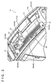
- the video camera 1 to which the embodiment has been applied is a business-use video camera of the type of being carried on a shoulder, and is used mainly for imaging outdoors.
- the video camera 1 includes a lens section 10 incorporating optical members for guiding an optical image from a subject to an image sensor in an apparatus body 11, and the apparatus body 11 for converting the optical image from the lens section 10 into an electrical signal so as to produce a picture signal.
- the lens section 10 has an imaging lens 12 which is provided on a front surface 11 a of the apparatus body 11 and which functions as an optical member for condensing the light coming from a subject.
- the lens section 10 has, for example, a zooming mechanism (not shown) and, by driving the zooming mechanism, it is possible to vary the optical magnification of the imaging lens 12 within a predetermined range.
- the apparatus body 11 forms a main body of the video camera 1 which is substantially rectangular parallelopiped in shape.
- a surface on one side in the longitudinal direction is the front surface 11 a, and a top surface 11c as an upper portion has a curved inclined surface sloping down from the side of a rear surface 11b toward the side of the front surface 11a.
- the apparatus body 11 is provided at its top surface 11c with a heat dissipating section 14 to be described later and a handle section 15.
- the apparatus body 11 is provided at its bottom surface 11d with a shoulder pad 16 which functions as a cushion when the user carries the video camera 1 on his or her shoulder, and a tripod mounting part 17 for fixing the apparatus body 11 onto a tripod or the like. Furthermore, a battery 18 is provided on the rear surface 11b of the apparatus body 11.
- the apparatus body 11 has a light receiving element (not shown) such as a CCD (Charge-Coupled Device) which receives the light condensed by the imaging lens 12 constituting an imaging unit and performs photo-electric conversion, thereby picking up an image of the subject.
- the apparatus body 11 has, for example, a spectral prism as an optical system by which the light condensed by the imaging lens 12 is separated into three primary color components, that is, red, green and blue components.
- the imaging unit is based on adoption of the so-called three-CCD system in which three CCDs are provided correspondingly to the separated color component.
- the apparatus body 11 as above has a picture signal processing circuit or the like for producing a picture signal according to the intensities of the light components receives the CCDs.
- CMOS complementary metal-oxide semiconductor device
- the three-CCD system also is merely an example.
- a recording and playback unit 19 for recording the picture signal outputted after the imaging at the light receiving element is incorporated in the apparatus body 11 near a side surface 11e on one side.
- the recording and playback unit 19 is provided somewhat closer to the rear surface 11b of the apparatus body 11.
- the recording and playback unit 19 has a mounting section for mounting a memory card incorporating a semiconductor memory such as a flash memory, and a memory card reader-writer by which recording and playback of information signals such as a picture signal and a sound signal are conducted in relation to the memory card mounted in the mounting section. Therefore, the apparatus body 11 has a function of recording the picture signal in the memory card or playing back the information recorded in the memory card.
- two IC card slots are provided in the side surface 11e of the apparatus body 11, in the state of being juxtaposed vertically.
- Such a recording and playback unit 19 is smaller in size, as compared with a recording and playback unit in which such a recording medium as a magnetic tape and an optical disk is used. This promises a reduction in the size of the apparatus as a whole and an enhanced degree of freedom in layout. Further, in the apparatus body 11, the recording and playback unit 19 is provided somewhat closer to the rear surface 11b of the apparatus body 11. This ensures that the top surface 11c of the apparatus body 11 can be shaped to be inclined more steeply, as compared with the case where the above-mentioned recording medium other than the memory card is used. Therefore, the apparatus body 11 can provide a wide field of view at the time of viewing the side of the video camera 1 carried on the user's shoulder, that is, at the time of overview.
- An editing operation unit (not shown) for operating predetermined functions of the video camera 1 and a display unit (not shown) are provided at a side surface 11f on the other side of the apparatus body 11. This permits the user to operate the editing operation unit while viewing the display unit.
- the display unit has, for example, a liquid crystal display panel, an organic EL panel, a CRT or the like.
- the recording and playback unit 19 is incorporated in the apparatus body 11 in the above-described example, the present invention may be embodied in such a manner that the apparatus body 11 is not provided therein with the recording and playback unit 19 and that recording and playback of information signals such as a picture signal are performed by use of a recording and playback unit connected to an external output terminal.
- the handle section 15 is provided so that the user can grip it by hand for holding the video camera 1 when the user brings the video camera 1 or when the video camera 1 is used at a low position.
- the shoulder pad 16 is formed in a concave shape at the bottom surface 11d of the apparatus body 11, and constitutes a part to be brought into contact with a user's shoulder when the video camera 1 is used in the state of being held on the user's shoulder.
- the shoulder pad 16 is formed by use of a soft or flexible material and in a shape having a curved surface.
- the tripod mounting part 17 is provided with screw holes for connecting a tripod and the apparatus body 11 to each other.
- a viewfinder is detachably mounted to the viewfinder mounting part 13.
- the viewfinder mounting part 13 is a plate-shaped member, and is provided, for example, with an engaging part for engagement with a mounting part of the viewfinder, and a stopper part for holding the viewfinder in the engaged state.
- the battery 18 is a lithium ion battery or the like, and serves as a driving power source for the above-mentioned zooming mechanism, the recording and playback unit 19 and the like.
- the apparatus body 11 configured as above includes, incorporated therein, not only the above-mentioned zooming mechanism, the recording and playback unit 19 and the image sensor but also a heat radiating part 20 for, for example, a power source by which predetermined electric power based on the power supplied from the battery 18 is supplied to the zooming mechanism, the recording and playback unit 19 and the image sensor. Accordingly, the heat dissipating section 14 for heat dissipation or release is provided at an upper portion of the apparatus body 11, as above-mentioned.
- the heat dissipating section 14 provided at the top surface 11 c constituting the upper portion of the video camera 1 configured as above will now be described in detail below.
- the heat dissipating section 14 is provided at the top surface 11c of the video camera 1.
- the heat dissipating section 14 has a recess 21 provided in the top surface 11c of the apparatus body 11, and a closing plate 22 mounted so as to the recess 21.
- the top surface 11c of the apparatus body 11 has a double-wall structure including a bottom surface of the recess 21 and the closing plate 22, with a space 23 being formed between the recess 21 and the losing plate 22. Further, as shown in FIGS.
- a drain port 24 making the space 23 communicate with the exterior is formed between the portion and the closing plate 22.
- the drain port 24 is an opening which is formed between the bottom surface of the recess 21 and the closing plate 22 on the front surface 11 a side, owing to a structure wherein the front surface 11 a side of the closing plate 22 is supported by a closing plate support piece 24a provided at the bottom surface of the recess 21, and which makes the space 23 communicate with the exterior.
- the recess 21 is provided in a substantially rectangular shape in the top surface 11c of the apparatus body 11.
- the bottom surface of the recess 21 is an inclined surface 25 sloping down from the side of the rear surface 11b toward the side of the front surface 11a of the apparatus body 11.
- the inclined surface 25 includes a first inclined surface 25a provided on the side of the rear surface 11b of the apparatus body 11, and a second inclined surface 25b which is provided on the side of the front surface 11 a, is continuous with the first inclined surface 25a, and is different from the first inclined surface 25a in angle of inclination.
- the first inclined surface 25a is formed along the inclined surface of the top surface 11c so as to have substantially the same inclination and curved surface as those of the inclined surface of the top surface 11c.
- the second inclined surface 25b is more gently inclined than the first inclined surface 25a, and causes the first inclined surface 25a and the top surface 11c of the apparatus body 11 to be continuous with each other.
- the inclined surface 25 constituting the bottom surface of the recess 21 has such an inclination as to generally slope down from the side of the rear surface 11b toward the side of the front surface 11a of the apparatus body 11, though the angle of inclination changes at an inflection part 25c at the boundary between the first inclined surface 25a and the second inclined surface 25b. Therefore, as indicated by arrow A in FIG.
- the inclined surface 25 constituting the bottom surface of the recess 21 conducts waterdrops, which have penetrated into the space 23, toward the side of the front surface 11a of the apparatus body 11, so that the waterdrops are drained through the drain port 24 to the exterior of the space 23.
- the inclined surface 25 is not limited to a curved inclined surface but may be a flat inclined surface.
- the bottom surface of the recess 21 is provided with a vent hole 26 through which the inside of the apparatus body 11 and the space 23 communicate with each other, and a first riser wall 27 provided adjacently to the vent hole 26 so as to rise toward the closing plate 22 side.
- the bottom surface of the recess 21 is provided with a first drain hole 28 formed in the second inclined surface 25b, and a second drain hole 29 formed on the rear surface 11b side of the first inclined surface 25a.
- fastening parts 30 for fastening the recess 21 and the closing plate 22 to each other, a picture operating unit 31 for operating a picture displayed on a display unit, and a handle mounting part 32 for mounting the handle section 15 to the apparatus body 11.
- the vent hole 26 is formed in the shape of a slot oriented along the longitudinal direction of the apparatus body 11.
- the vent hole 26 permits air heated by the heat radiating part 20 inside the apparatus body 11 to be discharged therethrough into the space 23.
- the first riser wall 27 is formed to rise toward the closing plate 22 side, along the whole periphery of the vent hole 26.
- the first riser wall 27 serves as a partition between the inclined surface 25 and the vent hole 26, thereby preventing the waterdrops guided onto the inclined surface 25 from penetrating via the vent hole 26 into the inside of the apparatus body 11.
- the first drain hole 28 is formed on the second inclined surface 25b in the vicinity of the inflection part 25c.
- a flexible first drain pipe 33 is connected to the first drain hole 28.
- the first drain pipe 33 is connected at its one end to the first drain hole 28, and is connected at its other end to a first bottom surface drain hole 34 formed in the bottom surface 11d of the apparatus body 11.
- the first drain pipe 33 is provided in the manner of being wound around a frame 11g, and is fixed to the frame 11 g by fixing members.
- the first bottom surface drain hole 34 is formed on the side of the front surface 11 a of the apparatus body 11, relative to the shoulder pad 16 provided on the bottom surface 11 d of the apparatus body 11. Accordingly, the first bottom surface drain hole 34 is so configured that the user's shoulder would not be wetted through the shoulder pad 16.
- the second drain hole 29 is formed in the first inclined surface 25a at a position in the vicinity of a corner part 35 formed by the bottom surface of the recess 21 and a wall surface, on the rear surface 11 b side, of the recess 21.
- a flexible second drain pipe 36 is connected to the second drain hole 29.
- the second drain pipe 36 is connected at its one end to the second drain hole 29, and is connected at its other end to a second bottom surface drain hole 37 formed in the bottom surface 11d of the apparatus body 11.
- the second drain pipe 36 is provided in the manner of being wound around the frame 11g of the apparatus body 11, and is fixed to the frame 11g by fixing members.
- the second bottom surface drain hole 37 is formed on the side of the rear surface 11 b of the apparatus body 11, relative to the shoulder pad 16 provided on the bottom surface 11 d of the apparatus body 11. Accordingly, the second bottom surface drain hole 37 is so configured that the user's shoulder would not be wetted through the shoulder pad 16.
- the fastening parts 30 are screw holes for fastening the recess 21 and the closing plate 22 to each other.
- a total of six fastening parts are provided in the recess 21, three on the side of the one-side side surface 11e of the apparatus body 11 and three on the side of the other-side side surface 11f of the apparatus body 11.
- Fastening members such as bolts are fastened to the fastening parts 30, whereby the recess 21 and the closing plate 22 are fastened to each other.
- the picture operating unit 31 has buttons for effecting operations of such functions as playback, pause, fast forward (picture search), rewind, etc.
- the picture operating unit 31 applies such operations as playback, pause, fast forward, rewind, etc. to a picture which is recorded in the memory card and displayed on the display unit provided at the side surface 11f on the other side of the apparatus body 11. Therefore, when the video camera 1 is put on an appropriate base or in other similar situations, the user can check the imaged picture by operating the picture operating unit 31.
- the handle mounting part 32 is a screw hole for fixing the handle section 15 and the frame 11g of the apparatus body 11 to each other.
- the closing plate 22 is composed of a thin plate having substantially the same shape and size as those of the recess 21, and closes the recess 21.
- the closing plate 22 is provided with heat dissipating holes 38 masking the space 23 communicate with the exterior, and is provided on the back side with a second riser wall 39 provided adjacently to the heat dissipating holes 38 so as to rise toward the recess 21 side.
- the closing plate 22 is provided with through-holes 40 for fastening to the recess 21, an operation window 41 for exposing an operating part of the recess 21 to the exterior, and an exposure port 42 for exposing the handle mounting part 32 of the recess 21 to the exterior, and is provided on the back side with support pieces 43 projecting toward the recess 21 side.
- the heat dissipating holes 38 are formed in the closing plate 22, each in the shape of a slot oriented in the width direction of the closing plate 22, and are formed in plurality and arrayed in parallel to the longitudinal direction.
- the heat dissipating holes 38 permit air discharged from the inside of the apparatus body 11 into the space 23 through the vent hole 26 to be discharged to the exterior.
- the heat dissipating holes 38 are positionally deviated from the vent hole 26. Specifically, the heat dissipating holes 38 are deviated from the vent hole 26 in the left-right direction so as not to overlap with the vent hole 26, as viewed from the top surface 11 c side. Therefore, the heat dissipating holes 38 prevent the waterdrops having penetrated through the heat dissipating holes 38 from entering into the inside of the apparatus body 11 directly through the vent hole 26.
- the second riser wall 39 is formed along the periphery of the heat dissipating holes 38 on the side opposed to the vent hole 26. In order that air discharged from the inside of the apparatus body 11 into the space 23 through the vent hole 26 can easily flow to the exterior, the second riser wall 39 is formed at such a height as not to overlap with the first riser wall 27.
- the second riser wall 39 guides waterdrops, which have penetrated via the heat dissipating holes 38 and have flowed along the back surface of the closing plate 22, to the inclined surface 25. This ensures that the waterdrops having penetrated via the heat dissipating holes 38 and flowed along the back surface of the closing plate 22 are prevented from entering into the inside of the apparatus body 11 through dropping on the vent hole 26.
- the through-holes 40 are provided at positions corresponding to the fastening parts 30 of the recess 21.
- the closing plate 22 is fastened to the recess 21 by a process in which the through-holes 40 are matched to the fastening parts 30 of the recess 21 and, thereafter, fastening members such as bolts are fastened to the fastening parts 30 of the recess 21 through the through-holes 40.
- the operation window 41 is provided with an opening 41a for exposing the operating part of the recess 21 to the exterior, and a lid 41b which is turnably supported on the recess 21 and is turned to open and close the opening 41a.
- the operation window 41 exposes the picture operating unit 31 at the recess 21 to the exterior via the opening 41a when the lid 41b is turned by the user so as to open the opening 41a.
- the exposure port 42 is provided at a position corresponding to the handle mounting part 32 of the recess 21. Therefore, the exposure port 42 exposes the handle mounting part 32 of the recess 21 to the exterior.
- the support pieces 43 are provided, for example, integrally with the second riser wall 39.
- the support pieces 43 are formed to have such heights as to make contact with the inclined surface 25, and at predetermined intervals along the longitudinal direction.
- the support pieces 43 are brought into contact with the bottom surface of the recess 21, support the closing plate 22, thereby enhance the rigidity of the closing plate 22, and give an enhanced mechanical strength.
- the closing plate 22 as above is formed by molding a synthetic resin.
- the closing plate 22 is formed from a synthetic resin or the like which is lower in thermal conductivity than metals or the like. Consequently, the closing plate 22 is not brought to a high temperature even when heated by air discharged via the vent hole 26, as compared with a closing plate formed of a metal or the like.
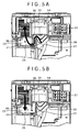
- the heat dissipating section 14 configured as above ensures that as indicated by arrow B in FIG. 5A , air heated by the heat radiating part 20 inside the apparatus body 11 is discharged from the inside of the apparatus body 11 into the space 23 through the vent hole 26 of the recess 21 provided at the top surface 11c of the apparatus body 11, and is thereafter discharged from the space 23 to the exterior via the heat dissipating holes 38. In this manner, the heat dissipating section 14 causes natural heat dissipation through an upper portion of the apparatus body 11, whereby the inside of the apparatus body 11 is cooled.
- the heat dissipating section 14 guides the waterdrops to the inclined surface 25, as indicated by arrow C in FIG. 5B , since the heat dissipating holes 38 and the vent hole 26 are positionally deviated from each other. Furthermore, the heat dissipating section 14 ensures that waterdrops having penetrated via the heat dissipating holes 38 and flowed along the back surface of the closing plate 22 are dropped onto the inclined surface 25 by the second riser wall 39, whereby the waterdrops are guided to the inclined surface 25. In this case, the heat dissipating section 14 ensures that the waterdrops guided to the inclined surface 25 are prevented, by the first riser wall 27, from entering into the inside of the apparatus body 11 via the vent hole 26.
- the heat dissipating section 14 ensures that when the user takes a roughly horizontal or low-angle shot or in other similar situations, waterdrops guided to the inclined surface 25 are conducted by the inclined surface 25 to the side of the front surface 11 a of the apparatus body 11, to be drained via the drain port 24 to the exterior of the space 23.
- the heat dissipating section 14 ensures that when the user takes a high-angle shot or in other similar situations, waterdrops flowing into the inflection part 25c after being guided to the inclined surface 25 are guided from the first drain hole 28 to the first bottom surface drain hole 34, to be drained to the outside of the apparatus body 11.
- the heat dissipating section 14 ensures that when the user takes a high-angle shot or in other similar situations, water drops flowing into the corner part 35 formed by the bottom surface of the recess 21 and that wall surface, on the rear surface 11b side, of the recess 21 are guided from the second drain hole 29 to the second bottom surface drain hole 37, to be drained to the exterior of the apparatus body 11.
- the video camera 1 in the video camera 1 according to an embodiment of the present invention, air heated inside the apparatus body 11 is discharged from the inside of the apparatus body 11 into the space 23 through the vent hole 26 of the recess 21 provided at the top surface 11c constituting an upper portion of the apparatus body 11, and is then discharged from the space 23 to the exterior through the heat dissipating holes 38.
- This makes it possible to dissipate heat through the upper portion of the apparatus body 11, and to realize an enhanced heat dissipating efficiency.
- the video camera 1 according to an embodiment of the present invention utilizes natural cooling, without using a cooling fan. This makes it possible to reduce the number of component parts, to reduce noise, and to suppress power consumption.
- the heat dissipating holes 38 and the vent hole 26 are positionally deviated from each other. Therefore, waterdrops having penetrated via the heat dissipating holes 38 can be guided to the inclined surface 25, and can be prevented from entering into the apparatus body 11 directly through the vent hole 26.
- the first riser wall 27 is formed on the bottom surface of the recess 21 adjacently to the vent hole 26. Therefore, waterdrops guided to the inclined surface 25 can be prevented from entering into the inside of the apparatus body 11 through the vent hole 26.
- the second riser wall 39 is formed on the back side of the closing plate 22 adjacently to the heat dissipating holes 38. This ensures that waterdrops having penetrated via the heat dissipating holes 38 and flowed along the back surface of the closing plate 22 can be dropped onto the inclined surface 25 and, hence, can be guided to the inclined surface 25. Consequently, the waterdrops can be prevented from entering into the inside of the apparatus body 11.
- the bottom surface of the recess 21 is the inclined surface 25 sloping down from the side of the rear surface 11b toward the side of the front surface 11a of the apparatus body 11, and the drain port 24 is formed between that portion of the recess 21 which is located on the side of the front surface 11a of the apparatus body 11 and the top surface 11c. Therefore, waterdrops guided to the inclined surface 25 can be conducted by the inclined surface 25 toward the side of the front surface 11a of the apparatus body 11, to be drained through the drain port 24 to the exterior of the space 23.
- the recording and playback unit 19 which uses a memory card as a recording medium and which can be made smaller in size than a recording and playback unit using other recording medium than the memory card, is provided somewhat closer to the rear surface 11b of the apparatus body 11. This ensures that the inclined surface 25 can be shaped to be inclined more steeply and that waterdrops guided to the inclined surface 25 can be guided toward the side of the front surface 11a of the apparatus body 11 more easily, as compared with the case where other recording medium than a memory card is used.
- the video camera 1 ensures that even when the user takes a high-angle shot, waterdrops flowing into the inflection part 25c after being guided to the inclined surface 25 can be conducted from the first drain hole 28 to the first bottom surface drain hole 34, to be drained to the exterior of the apparatus body 11.
- the video camera 1 ensures that even when the user takes a high-angle short, waterdrops flowing into the corner part 35 formed by the recess 21 and the wall surface, on the rear surface 11b side, of the recess 21 can be conducted from the second drain hole 29 to the second bottom surface drain hole 37, to be drained to the outside of the apparatus body 11.
- the drain holes may not necessarily be formed in the first inclined surface 25a and the second inclined surface 25b, and a drain hole may be formed in the inflection part 25c.
- the drain hole may be formed in only the first inclined surface 25a, may be formed in only the second inclined surface 25b, or may be formed in only the inflection part 25c.
- the drain hole is not limited to the one formed in the corner part 35 of the first inclined surface 25a, and the drain hole may be formed in other location on the first inclined surface 25a.
- the waterdrops guided to the inclined surface 25 may be drained to the exterior of the space 23 via the first drain hole 28 and the second drain hole 29.
- a cooling fan may be provided inside the apparatus body 11, and forced heat dissipation through an upper portion of the apparatus body 11 may be performed.
- the video camera 1 according to an embodiment of the present invention is not limited to the one that uses a memory card as a recording medium; for example, other recording media than the memory card, such as a magnetic tape, an optical disk, a hard disk, etc. may also be used.
- the video camera 1 according to an embodiment of the present invention is not limited to the one that is of the type of being carried on the user's shoulder; for example, a video camera of a handy type or an installed type may also be adopted.
- the imaging apparatus is not limited to a video camera but may be any one that consumes much power, has a high calorific value and is used mainly outdoors.
- Examples of such an imaging apparatus include a digital still camera, a camera using a silver salt film as a recording medium, etc.
- an imaging apparatus including an apparatus body in which a heat radiating part is disposed and a heat dissipating section formed at an upper portion of the apparatus body.
- the heat dissipating section has a recess provided in an upper portion of the apparatus body, and a closing plate mounted so as to close the recess.
- a space is formed between the recess and the closing plate.
- the recess is formed with a vent hole through which the inside of the apparatus body and the space communicate with each other.
- the closing plate is provided with a heat dissipating hole through which the space communicates with the exterior.
- the vent hole and the heat dissipating hole are positionally deviated, i.e. offset, from each other.
Landscapes
- Engineering & Computer Science (AREA)
- Physics & Mathematics (AREA)
- General Physics & Mathematics (AREA)
- Multimedia (AREA)
- Signal Processing (AREA)
- Aviation & Aerospace Engineering (AREA)
- Studio Devices (AREA)
- Cameras Adapted For Combination With Other Photographic Or Optical Apparatuses (AREA)
Description
- The present invention relates to an imaging apparatus in which a heat dissipating section having a heat dissipating function and an anti-waterdrop function is provided at an upper portion of an apparatus body.
- Of video cameras which are imaging apparatuses, video cameras for business use have large power consumptions and high calorific values. In such a business-use video camera, therefore, a cooling fan is provided inside a camera body to perform forced heat dissipation. However, the method of performing forced heat dissipation by a cooling fan leads to the generation of a cooling fan driving part and the generation of exhaust noise. In addition, such a method complicates the configuration of the camera body and increases power consumption due to the driving of the cooling fan.
- To cope with this problem, Japanese Patent Laid-open No.
Hei 11-26969 Patent Document 1, in which the vent hole is formed in the side surface, is not good in heat dissipating efficiency as compared with the forced heat dissipation by a cooling fan. - Furthermore, a video camera of the type of being carried on a shoulder, in general, is frequently used outdoors, so that it needs an anti-waterdrop function such as to prevent raindrops from entering into the inside of the camera body via the vent hole in a rainy weather.
-
US 2006/0256230 describes an imaging operation controller including: a casing, a control panel attached to a back part of the casing and provided with a plurality of operating members and function indicators indicating the functions of the operating members and placed near the operating members, respectively. - According to an embodiment of the present invention, there is provided an imaging apparatus including: an apparatus body in which a heat radiating part is disposed; and a heat dissipating section formed at an upper portion of the apparatus body. In the imaging apparatus, the heat dissipating section has a recess provided in an upper portion of the apparatus body, and a closing plate so mounted as to close the recess; a space is formed between the recess and the closing plate; the recess is formed with a vent hole through which the inside of the apparatus body and the space communicate with each other; the closing plate is provided with a heat dissipating hole through which the space communicates with the exterior; and the vent hole and the heat dissipating hole are positionally deviated from each other, characterised by a bottom surface of the recess is formed with a drain hole, and a drain pipe for conducting to a bottom surface of the apparatus body is connected to the drain hole.
- According to the embodiment of the present invention, air heated by a heat radiating part inside the apparatus body is discharged from the inside of the apparatus body into the space via the vent hole in the recess provided at an upper portion of the apparatus body, and, thereafter, the air is discharged from the space to the exterior via the heat dissipating hole positionally deviated from the vent hole. Consequently, heat can be dissipated efficiently through the upper portion of the apparatus body. Besides, since the vent hole and the heat dissipating hole are positionally deviated from each other, penetration of waterdrops into the inside of the apparatus body can be prevented while permitting heat to be dissipated through the upper portion of the apparatus body.
-
-
FIG. 1 is a perspective view of a video camera to which an embodiment of the present invention is applied; -
FIG. 2 is a bottom view of the video camera to which the embodiment is applied; -
FIG. 3 is a perspective view of a heat dissipating section; -
FIG. 4 is a perspective view of a recess in the heat dissipating section; -
FIGS. 5A and 5B are sectional views of the heat dissipating section, in whichFIG. 5A illustrates the flow of air during heat dissipation, andFIG. 5B illustrates the flow of waterdrops having penetrated into the heat dissipating section; -
FIG. 6 is a side view of an apparatus body; and -
FIG. 7 is a rear view of a closing plate in the heat dissipating section. - An embodiment for carrying out the present invention will be described, in the following order:
- 1. General configuration of video camera
- 2. Configuration of heat dissipating section
- 3. Working effect of video camera
- 4. Modifications
- A
video camera 1 to which an embodiment of the present invention has been applied will be described referring to the drawings. - As shown in
FIGS. 1 and2 , thevideo camera 1 to which the embodiment has been applied is a business-use video camera of the type of being carried on a shoulder, and is used mainly for imaging outdoors. - The
video camera 1 includes alens section 10 incorporating optical members for guiding an optical image from a subject to an image sensor in anapparatus body 11, and theapparatus body 11 for converting the optical image from thelens section 10 into an electrical signal so as to produce a picture signal. - The
lens section 10 has animaging lens 12 which is provided on afront surface 11 a of theapparatus body 11 and which functions as an optical member for condensing the light coming from a subject. In addition, thelens section 10 has, for example, a zooming mechanism (not shown) and, by driving the zooming mechanism, it is possible to vary the optical magnification of theimaging lens 12 within a predetermined range. - The
apparatus body 11 forms a main body of thevideo camera 1 which is substantially rectangular parallelopiped in shape. Of theapparatus body 11, a surface on one side in the longitudinal direction is thefront surface 11 a, and atop surface 11c as an upper portion has a curved inclined surface sloping down from the side of arear surface 11b toward the side of thefront surface 11a. At thefront surface 11a of theapparatus body 11, there are provided the above-mentionedlens section 10 and aviewfinder mounting part 13 on which to mount a viewfinder. Besides, theapparatus body 11 is provided at itstop surface 11c with aheat dissipating section 14 to be described later and ahandle section 15. Further, theapparatus body 11 is provided at itsbottom surface 11d with ashoulder pad 16 which functions as a cushion when the user carries thevideo camera 1 on his or her shoulder, and atripod mounting part 17 for fixing theapparatus body 11 onto a tripod or the like. Furthermore, abattery 18 is provided on therear surface 11b of theapparatus body 11. - Further, the
apparatus body 11 has a light receiving element (not shown) such as a CCD (Charge-Coupled Device) which receives the light condensed by theimaging lens 12 constituting an imaging unit and performs photo-electric conversion, thereby picking up an image of the subject. Theapparatus body 11 has, for example, a spectral prism as an optical system by which the light condensed by theimaging lens 12 is separated into three primary color components, that is, red, green and blue components. The imaging unit is based on adoption of the so-called three-CCD system in which three CCDs are provided correspondingly to the separated color component. Theapparatus body 11 as above has a picture signal processing circuit or the like for producing a picture signal according to the intensities of the light components receives the CCDs. Incidentally, while the CCD is used as the light receiving element here, this is not limitative. For example, a CMOS (complementary metal-oxide semiconductor device) or the like may be used as a photo-electric conversion element for performing efficient photo-electric conversion. Besides, the three-CCD system also is merely an example. - Furthermore, a recording and
playback unit 19 for recording the picture signal outputted after the imaging at the light receiving element is incorporated in theapparatus body 11 near aside surface 11e on one side. The recording andplayback unit 19 is provided somewhat closer to therear surface 11b of theapparatus body 11. The recording andplayback unit 19 has a mounting section for mounting a memory card incorporating a semiconductor memory such as a flash memory, and a memory card reader-writer by which recording and playback of information signals such as a picture signal and a sound signal are conducted in relation to the memory card mounted in the mounting section. Therefore, theapparatus body 11 has a function of recording the picture signal in the memory card or playing back the information recorded in the memory card. Here, two IC card slots are provided in theside surface 11e of theapparatus body 11, in the state of being juxtaposed vertically. - Such a recording and
playback unit 19 is smaller in size, as compared with a recording and playback unit in which such a recording medium as a magnetic tape and an optical disk is used. This promises a reduction in the size of the apparatus as a whole and an enhanced degree of freedom in layout. Further, in theapparatus body 11, the recording andplayback unit 19 is provided somewhat closer to therear surface 11b of theapparatus body 11. This ensures that thetop surface 11c of theapparatus body 11 can be shaped to be inclined more steeply, as compared with the case where the above-mentioned recording medium other than the memory card is used. Therefore, theapparatus body 11 can provide a wide field of view at the time of viewing the side of thevideo camera 1 carried on the user's shoulder, that is, at the time of overview. - An editing operation unit (not shown) for operating predetermined functions of the
video camera 1 and a display unit (not shown) are provided at aside surface 11f on the other side of theapparatus body 11. This permits the user to operate the editing operation unit while viewing the display unit. Besides, the display unit has, for example, a liquid crystal display panel, an organic EL panel, a CRT or the like. - Incidentally, while the recording and
playback unit 19 is incorporated in theapparatus body 11 in the above-described example, the present invention may be embodied in such a manner that theapparatus body 11 is not provided therein with the recording andplayback unit 19 and that recording and playback of information signals such as a picture signal are performed by use of a recording and playback unit connected to an external output terminal. - The
handle section 15 is provided so that the user can grip it by hand for holding thevideo camera 1 when the user brings thevideo camera 1 or when thevideo camera 1 is used at a low position. - The
shoulder pad 16 is formed in a concave shape at thebottom surface 11d of theapparatus body 11, and constitutes a part to be brought into contact with a user's shoulder when thevideo camera 1 is used in the state of being held on the user's shoulder. For making it easy to hold thevideo camera 1 on the user's shoulder, theshoulder pad 16 is formed by use of a soft or flexible material and in a shape having a curved surface. - The
tripod mounting part 17 is provided with screw holes for connecting a tripod and theapparatus body 11 to each other. - A viewfinder is detachably mounted to the
viewfinder mounting part 13. Theviewfinder mounting part 13 is a plate-shaped member, and is provided, for example, with an engaging part for engagement with a mounting part of the viewfinder, and a stopper part for holding the viewfinder in the engaged state. - The
battery 18 is a lithium ion battery or the like, and serves as a driving power source for the above-mentioned zooming mechanism, the recording andplayback unit 19 and the like. - The
apparatus body 11 configured as above includes, incorporated therein, not only the above-mentioned zooming mechanism, the recording andplayback unit 19 and the image sensor but also aheat radiating part 20 for, for example, a power source by which predetermined electric power based on the power supplied from thebattery 18 is supplied to the zooming mechanism, the recording andplayback unit 19 and the image sensor. Accordingly, theheat dissipating section 14 for heat dissipation or release is provided at an upper portion of theapparatus body 11, as above-mentioned. - The
heat dissipating section 14 provided at thetop surface 11 c constituting the upper portion of thevideo camera 1 configured as above will now be described in detail below. - As shown in
FIGS. 3 and4 , theheat dissipating section 14 is provided at thetop surface 11c of thevideo camera 1. Theheat dissipating section 14 has arecess 21 provided in thetop surface 11c of theapparatus body 11, and aclosing plate 22 mounted so as to therecess 21. As shown inFIGS. 5A and 5B , thetop surface 11c of theapparatus body 11 has a double-wall structure including a bottom surface of therecess 21 and theclosing plate 22, with aspace 23 being formed between therecess 21 and the losingplate 22. Further, as shown inFIGS. 3 and4 , at that portion of therecess 21 which is located on the side of thefront surface 11 a of theapparatus body 11, adrain port 24 making thespace 23 communicate with the exterior is formed between the portion and theclosing plate 22. Thedrain port 24 is an opening which is formed between the bottom surface of therecess 21 and theclosing plate 22 on thefront surface 11 a side, owing to a structure wherein thefront surface 11 a side of theclosing plate 22 is supported by a closing plate support piece 24a provided at the bottom surface of therecess 21, and which makes thespace 23 communicate with the exterior. - As shown in
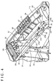
FIG. 4 , therecess 21 is provided in a substantially rectangular shape in thetop surface 11c of theapparatus body 11. The bottom surface of therecess 21 is aninclined surface 25 sloping down from the side of therear surface 11b toward the side of thefront surface 11a of theapparatus body 11. Specifically, theinclined surface 25 includes a firstinclined surface 25a provided on the side of therear surface 11b of theapparatus body 11, and a secondinclined surface 25b which is provided on the side of thefront surface 11 a, is continuous with the firstinclined surface 25a, and is different from the firstinclined surface 25a in angle of inclination. The firstinclined surface 25a is formed along the inclined surface of thetop surface 11c so as to have substantially the same inclination and curved surface as those of the inclined surface of thetop surface 11c. The secondinclined surface 25b is more gently inclined than the firstinclined surface 25a, and causes the firstinclined surface 25a and thetop surface 11c of theapparatus body 11 to be continuous with each other. In other words, theinclined surface 25 constituting the bottom surface of therecess 21 has such an inclination as to generally slope down from the side of therear surface 11b toward the side of thefront surface 11a of theapparatus body 11, though the angle of inclination changes at aninflection part 25c at the boundary between the firstinclined surface 25a and the secondinclined surface 25b. Therefore, as indicated by arrow A inFIG. 4 , theinclined surface 25 constituting the bottom surface of therecess 21 conducts waterdrops, which have penetrated into thespace 23, toward the side of thefront surface 11a of theapparatus body 11, so that the waterdrops are drained through thedrain port 24 to the exterior of thespace 23. Incidentally, theinclined surface 25 is not limited to a curved inclined surface but may be a flat inclined surface. - The bottom surface of the
recess 21 is provided with avent hole 26 through which the inside of theapparatus body 11 and thespace 23 communicate with each other, and afirst riser wall 27 provided adjacently to thevent hole 26 so as to rise toward the closingplate 22 side. In addition, the bottom surface of therecess 21 is provided with afirst drain hole 28 formed in the secondinclined surface 25b, and asecond drain hole 29 formed on therear surface 11b side of the firstinclined surface 25a. Further, at the bottom surface of therecess 21, there are providedfastening parts 30 for fastening therecess 21 and theclosing plate 22 to each other, apicture operating unit 31 for operating a picture displayed on a display unit, and ahandle mounting part 32 for mounting thehandle section 15 to theapparatus body 11. - The
vent hole 26 is formed in the shape of a slot oriented along the longitudinal direction of theapparatus body 11. Thevent hole 26 permits air heated by theheat radiating part 20 inside theapparatus body 11 to be discharged therethrough into thespace 23. - The
first riser wall 27 is formed to rise toward the closingplate 22 side, along the whole periphery of thevent hole 26. Thefirst riser wall 27 serves as a partition between theinclined surface 25 and thevent hole 26, thereby preventing the waterdrops guided onto theinclined surface 25 from penetrating via thevent hole 26 into the inside of theapparatus body 11. - The
first drain hole 28 is formed on the secondinclined surface 25b in the vicinity of theinflection part 25c. As shown inFIG. 6 , a flexiblefirst drain pipe 33 is connected to thefirst drain hole 28. Thefirst drain pipe 33 is connected at its one end to thefirst drain hole 28, and is connected at its other end to a first bottomsurface drain hole 34 formed in thebottom surface 11d of theapparatus body 11. Besides, thefirst drain pipe 33 is provided in the manner of being wound around aframe 11g, and is fixed to theframe 11 g by fixing members. - Therefore, when the bottom surface of the
recess 21 is disposed to be higher on thefront surface 11 a side than on therear surface 11 b side such as when the user takes a high-angle shot, the waterdrops flowing into theinflection part 25c forming a hollow are guided by thefirst drain pipe 33 from thefirst drain hole 28 to the first bottomsurface drain hole 34, to be drained to the exterior of theapparatus body 11. In this case, the first bottomsurface drain hole 34 is formed on the side of thefront surface 11 a of theapparatus body 11, relative to theshoulder pad 16 provided on thebottom surface 11 d of theapparatus body 11. Accordingly, the first bottomsurface drain hole 34 is so configured that the user's shoulder would not be wetted through theshoulder pad 16. - As shown in
FIG. 4 , thesecond drain hole 29 is formed in the firstinclined surface 25a at a position in the vicinity of acorner part 35 formed by the bottom surface of therecess 21 and a wall surface, on therear surface 11 b side, of therecess 21. As shown inFIG. 6 , a flexiblesecond drain pipe 36 is connected to thesecond drain hole 29. Thesecond drain pipe 36 is connected at its one end to thesecond drain hole 29, and is connected at its other end to a second bottomsurface drain hole 37 formed in thebottom surface 11d of theapparatus body 11. Besides, thesecond drain pipe 36 is provided in the manner of being wound around theframe 11g of theapparatus body 11, and is fixed to theframe 11g by fixing members. - Therefore, when the bottom surface of the
recess 21 is disposed to higher on thefront surface 11a side than on therear surface 11b side such as when the user takes a high angle shot, the waterdrops flowing into thecorner part 35 formed by the bottom surface of therecess 21 and the wall surface, on therear surface 11b side, of therecess 21 are guided by thesecond drain pipe 36 from thesecond drain hole 29 to the second bottomsurface drain hole 37, to be drained to the outside of theapparatus body 11. In this case, the second bottomsurface drain hole 37 is formed on the side of therear surface 11 b of theapparatus body 11, relative to theshoulder pad 16 provided on thebottom surface 11 d of theapparatus body 11. Accordingly, the second bottomsurface drain hole 37 is so configured that the user's shoulder would not be wetted through theshoulder pad 16. - As shown in
FIG. 4 , thefastening parts 30 are screw holes for fastening therecess 21 and theclosing plate 22 to each other. For example, a total of six fastening parts are provided in therecess 21, three on the side of the one-side side surface 11e of theapparatus body 11 and three on the side of the other-side side surface 11f of theapparatus body 11. Fastening members such as bolts are fastened to thefastening parts 30, whereby therecess 21 and theclosing plate 22 are fastened to each other. - The
picture operating unit 31 has buttons for effecting operations of such functions as playback, pause, fast forward (picture search), rewind, etc. Thepicture operating unit 31 applies such operations as playback, pause, fast forward, rewind, etc. to a picture which is recorded in the memory card and displayed on the display unit provided at theside surface 11f on the other side of theapparatus body 11. Therefore, when thevideo camera 1 is put on an appropriate base or in other similar situations, the user can check the imaged picture by operating thepicture operating unit 31. - The
handle mounting part 32 is a screw hole for fixing thehandle section 15 and theframe 11g of theapparatus body 11 to each other. Thehandle section 15, which is mounted at its one end to the mounting part (not shown) of thetop surface 11c of theapparatus body 11, is fastened at its other end to thehandle mounting part 32 by a fastening member such as a bolt. Consequently, thehandle section 15 is mounted to theapparatus body 11. - As shown in
FIGS. 3 and7 , the closingplate 22 is composed of a thin plate having substantially the same shape and size as those of therecess 21, and closes therecess 21. The closingplate 22 is provided withheat dissipating holes 38 masking thespace 23 communicate with the exterior, and is provided on the back side with asecond riser wall 39 provided adjacently to theheat dissipating holes 38 so as to rise toward therecess 21 side. Besides, the closingplate 22 is provided with through-holes 40 for fastening to therecess 21, anoperation window 41 for exposing an operating part of therecess 21 to the exterior, and anexposure port 42 for exposing thehandle mounting part 32 of therecess 21 to the exterior, and is provided on the back side withsupport pieces 43 projecting toward therecess 21 side. - The
heat dissipating holes 38 are formed in theclosing plate 22, each in the shape of a slot oriented in the width direction of theclosing plate 22, and are formed in plurality and arrayed in parallel to the longitudinal direction. Theheat dissipating holes 38 permit air discharged from the inside of theapparatus body 11 into thespace 23 through thevent hole 26 to be discharged to the exterior. Further, as shown inFIG. 5 , theheat dissipating holes 38 are positionally deviated from thevent hole 26. Specifically, theheat dissipating holes 38 are deviated from thevent hole 26 in the left-right direction so as not to overlap with thevent hole 26, as viewed from thetop surface 11 c side. Therefore, theheat dissipating holes 38 prevent the waterdrops having penetrated through theheat dissipating holes 38 from entering into the inside of theapparatus body 11 directly through thevent hole 26. - The
second riser wall 39 is formed along the periphery of theheat dissipating holes 38 on the side opposed to thevent hole 26. In order that air discharged from the inside of theapparatus body 11 into thespace 23 through thevent hole 26 can easily flow to the exterior, thesecond riser wall 39 is formed at such a height as not to overlap with thefirst riser wall 27. Thesecond riser wall 39 guides waterdrops, which have penetrated via theheat dissipating holes 38 and have flowed along the back surface of theclosing plate 22, to theinclined surface 25. This ensures that the waterdrops having penetrated via theheat dissipating holes 38 and flowed along the back surface of theclosing plate 22 are prevented from entering into the inside of theapparatus body 11 through dropping on thevent hole 26. - The through-
holes 40 are provided at positions corresponding to thefastening parts 30 of therecess 21. The closingplate 22 is fastened to therecess 21 by a process in which the through-holes 40 are matched to thefastening parts 30 of therecess 21 and, thereafter, fastening members such as bolts are fastened to thefastening parts 30 of therecess 21 through the through-holes 40. - The
operation window 41 is provided with anopening 41a for exposing the operating part of therecess 21 to the exterior, and alid 41b which is turnably supported on therecess 21 and is turned to open and close theopening 41a. Theoperation window 41 exposes thepicture operating unit 31 at therecess 21 to the exterior via theopening 41a when thelid 41b is turned by the user so as to open theopening 41a. - The
exposure port 42 is provided at a position corresponding to thehandle mounting part 32 of therecess 21. Therefore, theexposure port 42 exposes thehandle mounting part 32 of therecess 21 to the exterior. - The
support pieces 43 are provided, for example, integrally with thesecond riser wall 39. Thesupport pieces 43 are formed to have such heights as to make contact with theinclined surface 25, and at predetermined intervals along the longitudinal direction. Thesupport pieces 43 are brought into contact with the bottom surface of therecess 21, support theclosing plate 22, thereby enhance the rigidity of theclosing plate 22, and give an enhanced mechanical strength. - The closing
plate 22 as above is formed by molding a synthetic resin. The closingplate 22 is formed from a synthetic resin or the like which is lower in thermal conductivity than metals or the like. Consequently, the closingplate 22 is not brought to a high temperature even when heated by air discharged via thevent hole 26, as compared with a closing plate formed of a metal or the like. - The
heat dissipating section 14 configured as above ensures that as indicated by arrow B inFIG. 5A , air heated by theheat radiating part 20 inside theapparatus body 11 is discharged from the inside of theapparatus body 11 into thespace 23 through thevent hole 26 of therecess 21 provided at thetop surface 11c of theapparatus body 11, and is thereafter discharged from thespace 23 to the exterior via the heat dissipating holes 38. In this manner, theheat dissipating section 14 causes natural heat dissipation through an upper portion of theapparatus body 11, whereby the inside of theapparatus body 11 is cooled. - Further, in the case where waterdrops or the like have penetrated via the
heat dissipating holes 38, theheat dissipating section 14 guides the waterdrops to theinclined surface 25, as indicated by arrow C inFIG. 5B , since theheat dissipating holes 38 and thevent hole 26 are positionally deviated from each other. Furthermore, theheat dissipating section 14 ensures that waterdrops having penetrated via theheat dissipating holes 38 and flowed along the back surface of theclosing plate 22 are dropped onto theinclined surface 25 by thesecond riser wall 39, whereby the waterdrops are guided to theinclined surface 25. In this case, theheat dissipating section 14 ensures that the waterdrops guided to theinclined surface 25 are prevented, by thefirst riser wall 27, from entering into the inside of theapparatus body 11 via thevent hole 26. - Besides, the
heat dissipating section 14 ensures that when the user takes a roughly horizontal or low-angle shot or in other similar situations, waterdrops guided to theinclined surface 25 are conducted by theinclined surface 25 to the side of thefront surface 11 a of theapparatus body 11, to be drained via thedrain port 24 to the exterior of thespace 23. In addition, theheat dissipating section 14 ensures that when the user takes a high-angle shot or in other similar situations, waterdrops flowing into theinflection part 25c after being guided to theinclined surface 25 are guided from thefirst drain hole 28 to the first bottomsurface drain hole 34, to be drained to the outside of theapparatus body 11. Further, theheat dissipating section 14 ensures that when the user takes a high-angle shot or in other similar situations, water drops flowing into thecorner part 35 formed by the bottom surface of therecess 21 and that wall surface, on therear surface 11b side, of therecess 21 are guided from thesecond drain hole 29 to the second bottomsurface drain hole 37, to be drained to the exterior of theapparatus body 11. - As above-described, in the
video camera 1 according to an embodiment of the present invention, air heated inside theapparatus body 11 is discharged from the inside of theapparatus body 11 into thespace 23 through thevent hole 26 of therecess 21 provided at thetop surface 11c constituting an upper portion of theapparatus body 11, and is then discharged from thespace 23 to the exterior through the heat dissipating holes 38. This makes it possible to dissipate heat through the upper portion of theapparatus body 11, and to realize an enhanced heat dissipating efficiency. Further, thevideo camera 1 according to an embodiment of the present invention utilizes natural cooling, without using a cooling fan. This makes it possible to reduce the number of component parts, to reduce noise, and to suppress power consumption. - Furthermore, in the
video camera 1 according to an embodiment of the present invention, theheat dissipating holes 38 and thevent hole 26 are positionally deviated from each other. Therefore, waterdrops having penetrated via theheat dissipating holes 38 can be guided to theinclined surface 25, and can be prevented from entering into theapparatus body 11 directly through thevent hole 26. - In addition, in the
video camera 1 according to an embodiment of the present invention, thefirst riser wall 27 is formed on the bottom surface of therecess 21 adjacently to thevent hole 26. Therefore, waterdrops guided to theinclined surface 25 can be prevented from entering into the inside of theapparatus body 11 through thevent hole 26. - Besides, in the
video camera 1 according to an embodiment of the present invention, thesecond riser wall 39 is formed on the back side of theclosing plate 22 adjacently to the heat dissipating holes 38. This ensures that waterdrops having penetrated via theheat dissipating holes 38 and flowed along the back surface of theclosing plate 22 can be dropped onto theinclined surface 25 and, hence, can be guided to theinclined surface 25. Consequently, the waterdrops can be prevented from entering into the inside of theapparatus body 11. - Further, in the
video camera 1 according to an embodiment of the present invention, the bottom surface of therecess 21 is theinclined surface 25 sloping down from the side of therear surface 11b toward the side of thefront surface 11a of theapparatus body 11, and thedrain port 24 is formed between that portion of therecess 21 which is located on the side of thefront surface 11a of theapparatus body 11 and thetop surface 11c. Therefore, waterdrops guided to theinclined surface 25 can be conducted by theinclined surface 25 toward the side of thefront surface 11a of theapparatus body 11, to be drained through thedrain port 24 to the exterior of thespace 23. - In addition, in the
video camera 1 according to an embodiment of the present invention, the recording andplayback unit 19, which uses a memory card as a recording medium and which can be made smaller in size than a recording and playback unit using other recording medium than the memory card, is provided somewhat closer to therear surface 11b of theapparatus body 11. This ensures that theinclined surface 25 can be shaped to be inclined more steeply and that waterdrops guided to theinclined surface 25 can be guided toward the side of thefront surface 11a of theapparatus body 11 more easily, as compared with the case where other recording medium than a memory card is used. - Besides, the
video camera 1 according to an embodiment of the present invention ensures that even when the user takes a high-angle shot, waterdrops flowing into theinflection part 25c after being guided to theinclined surface 25 can be conducted from thefirst drain hole 28 to the first bottomsurface drain hole 34, to be drained to the exterior of theapparatus body 11. - Furthermore, the
video camera 1 according to an embodiment of the present invention ensures that even when the user takes a high-angle short, waterdrops flowing into thecorner part 35 formed by therecess 21 and the wall surface, on therear surface 11b side, of therecess 21 can be conducted from thesecond drain hole 29 to the second bottomsurface drain hole 37, to be drained to the outside of theapparatus body 11. - Incidentally, in the
video camera 1 according to an embodiment of the present invention, the drain holes may not necessarily be formed in the firstinclined surface 25a and the secondinclined surface 25b, and a drain hole may be formed in theinflection part 25c. Besides, in thevideo camera 1 according to an embodiment of the invention, the drain hole may be formed in only the firstinclined surface 25a, may be formed in only the secondinclined surface 25b, or may be formed in only theinflection part 25c. Further, in thevideo camera 1 according to an embodiment of the invention, the drain hole is not limited to the one formed in thecorner part 35 of the firstinclined surface 25a, and the drain hole may be formed in other location on the firstinclined surface 25a. - In addition, in the
video camera 1 according to an embodiment of the present invention, instead of providing thedrain port 24 between therecess 21 and theclosing plate 22, the waterdrops guided to theinclined surface 25 may be drained to the exterior of thespace 23 via thefirst drain hole 28 and thesecond drain hole 29. - Besides, in the
video camera 1 according to an embodiment of the present invention, a cooling fan may be provided inside theapparatus body 11, and forced heat dissipation through an upper portion of theapparatus body 11 may be performed. - Further, the
video camera 1 according to an embodiment of the present invention is not limited to the one that uses a memory card as a recording medium; for example, other recording media than the memory card, such as a magnetic tape, an optical disk, a hard disk, etc. may also be used. In addition, thevideo camera 1 according to an embodiment of the present invention is not limited to the one that is of the type of being carried on the user's shoulder; for example, a video camera of a handy type or an installed type may also be adopted. - Further, the imaging apparatus according to an embodiment of the present invention is not limited to a video camera but may be any one that consumes much power, has a high calorific value and is used mainly outdoors. Examples of such an imaging apparatus include a digital still camera, a camera using a silver salt film as a recording medium, etc.
- In summary, an imaging apparatus is provided including an apparatus body in which a heat radiating part is disposed and a heat dissipating section formed at an upper portion of the apparatus body. The heat dissipating section has a recess provided in an upper portion of the apparatus body, and a closing plate mounted so as to close the recess. A space is formed between the recess and the closing plate. The recess is formed with a vent hole through which the inside of the apparatus body and the space communicate with each other. The closing plate is provided with a heat dissipating hole through which the space communicates with the exterior. The vent hole and the heat dissipating hole are positionally deviated, i.e. offset, from each other.
- It should be understood by those skilled in the art that various modifications, combinations, sub-combinations and alternations may occur depending on design requirements and other factors insofar as they are within the scope of the appended claims.
- The present application contains subject matter related to that disclosed in Japanese Priority Patent Application
JP 2009-262094
Claims (8)
- An imaging apparatus (1) comprising:an apparatus body (11) in which a heat radiating part is disposed; anda heat dissipating section (14) formed at an upper portion of the apparatus body, whereinthe heat dissipating section (14) has a recess (21) provided in an upper portion of the apparatus body (11), and a closing plate (22) so mounted as to close the recess,a space (23) is formed between the recess (21) and the closing plate (22),the recess (21) is formed with a vent hole (26) through which the inside of the apparatus body (11) and the space (23) communicate with each other,the closing plate (22) is provided with a heat dissipating hole (38) through which the space (23) communicates with the exterior, andthe vent hole (26) and the heat dissipating hole (38) are positionally deviated from each other,characterised by a bottom surface of the recess (21) is formed with a drain hole (28,29), and
a drain pipe (33, 36) for conducting to a bottom surface of the apparatus body (11) is connected to the drain hole (28,29). - The imaging apparatus according to claim 1, wherein the recess is formed with a first riser wall adjacently to the vent hole.
- The imaging apparatus according to claim 2, wherein the closing plate is formed on a back side thereof with a second riser wall adjacently to the heat dissipating hole.
- The imaging apparatus according to claim 3, wherein a bottom surface of the recess is an inclined surface sloping down from the side of a rear surface toward the side of a front surface of the apparatus body.
- The imaging apparatus according to claim 3, wherein
a bottom surface of the recess has a first inclined surface sloping down from the side of a rear surface toward the side of a front surface of the apparatus body, and a second inclined surface continuous with the first inclined surface and different from the first inclined surface in angle of inclination;
the first inclined surface is formed with the drain hole. - The imaging apparatus according to claim 3, wherein
a bottom surface of the recess has a first inclined surface sloping down from the side of a rear surface toward the side of a front surface of the apparatus body, and a second inclined surface continuous with the first inclined surface and different from the first inclined surface in angle of inclination;
the second inclined surface is formed with the drain hole. - The imaging apparatus according to claim 3, wherein
a bottom surface of the recess has a first inclined surface sloping down from the side of a rear surface toward the side of a front surface of the apparatus body, and a second inclined surface continuous with the first inclined surface and different from the first inclined surface in angle of inclination;
the first inclined surface and the second inclined surface are formed with the drain hole. - The imaging apparatus according to claim 1, wherein that portion of the recess which is located on the side of a front surface of the apparatus body is formed with a drain port between itself and the closing plate.
Applications Claiming Priority (1)
| Application Number | Priority Date | Filing Date | Title |
|---|---|---|---|
| JP2009262094A JP5487897B2 (en) | 2009-11-17 | 2009-11-17 | Imaging device |
Publications (2)
| Publication Number | Publication Date |
|---|---|
| EP2339825A1 EP2339825A1 (en) | 2011-06-29 |
| EP2339825B1 true EP2339825B1 (en) | 2012-08-22 |
Family
ID=43587202
Family Applications (1)
| Application Number | Title | Priority Date | Filing Date |
|---|---|---|---|
| EP10187386A Not-in-force EP2339825B1 (en) | 2009-11-17 | 2010-10-13 | Imaging Apparatus |
Country Status (4)
| Country | Link |
|---|---|
| US (1) | US8600222B2 (en) |
| EP (1) | EP2339825B1 (en) |
| JP (1) | JP5487897B2 (en) |
| CN (1) | CN102075673A (en) |
Families Citing this family (4)
| Publication number | Priority date | Publication date | Assignee | Title |
|---|---|---|---|---|
| US7154175B2 (en) | 2004-06-21 | 2006-12-26 | Intel Corporation | Ground plane for integrated circuit package |
| WO2016031369A1 (en) | 2014-08-29 | 2016-03-03 | ソニー株式会社 | Imaging apparatus |
| US10133158B2 (en) * | 2016-10-17 | 2018-11-20 | Panasonic Intellectual Property Management Co., Ltd. | Imaging device |
| JP1613026S (en) * | 2017-12-28 | 2018-09-10 |
Family Cites Families (13)
| Publication number | Priority date | Publication date | Assignee | Title |
|---|---|---|---|---|
| US1604765A (en) * | 1924-01-28 | 1926-10-26 | Photostat Corp | Photographic apparatus |
| US2315406A (en) * | 1942-02-28 | 1943-03-30 | Balaban & Katz Corp | Television camera |
| JPH1126969A (en) | 1997-06-30 | 1999-01-29 | Canon Inc | Portable apparatus |
| US6061087A (en) * | 1998-07-16 | 2000-05-09 | Sensormatic Electronics Corporation | Outdoor enclosure for video surveillance system |
| US6728480B1 (en) * | 2003-03-06 | 2004-04-27 | Elmo Co., Ltd. | Casing with improved drain hole |
| JP2005063534A (en) * | 2003-08-08 | 2005-03-10 | Sony Corp | Disk recording and/or reproducing device |
| JP2005063560A (en) * | 2003-08-12 | 2005-03-10 | Sony Corp | Disk recording and/or playback device |
| JP4687210B2 (en) * | 2005-04-14 | 2011-05-25 | ソニー株式会社 | Imaging control device |
| JP4442497B2 (en) * | 2005-04-14 | 2010-03-31 | ソニー株式会社 | Camera and imaging control device |
| JP4672530B2 (en) * | 2005-11-17 | 2011-04-20 | 日東電工株式会社 | Ventilation member |
| JP4770854B2 (en) * | 2008-03-19 | 2011-09-14 | カシオ計算機株式会社 | Digital camera |
| JP5251233B2 (en) | 2008-04-28 | 2013-07-31 | 株式会社Ihi | How to paint the cylinder |
| CN201203745Y (en) * | 2008-05-09 | 2009-03-04 | 李鸿 | Heat-extraction waterproof infrared ball type camera |
-
2009
- 2009-11-17 JP JP2009262094A patent/JP5487897B2/en not_active Expired - Fee Related
-
2010
- 2010-10-13 EP EP10187386A patent/EP2339825B1/en not_active Not-in-force
- 2010-11-10 US US12/943,169 patent/US8600222B2/en not_active Expired - Fee Related
- 2010-11-10 CN CN2010105413017A patent/CN102075673A/en active Pending
Also Published As
| Publication number | Publication date |
|---|---|
| US20110116774A1 (en) | 2011-05-19 |
| CN102075673A (en) | 2011-05-25 |
| JP2011109393A (en) | 2011-06-02 |
| JP5487897B2 (en) | 2014-05-14 |
| EP2339825A1 (en) | 2011-06-29 |
| US8600222B2 (en) | 2013-12-03 |
Similar Documents
| Publication | Publication Date | Title |
|---|---|---|
| JP7076996B2 (en) | Electronics | |
| US8106952B2 (en) | Imaging device unit and imaging apparatus | |
| US8488317B2 (en) | Image pickup apparatus and electronic device | |
| JP2008011233A (en) | Photographic apparatus | |
| JP7362449B2 (en) | Imaging device | |
| EP2339825B1 (en) | Imaging Apparatus | |
| JP7016678B2 (en) | A heat dissipation module and a system camera equipped with a heat dissipation module | |
| JP2017069500A (en) | Heat dissipation structure of electronic apparatus | |
| US11822215B2 (en) | Image capturing apparatus having a fan that generates air flow in a duct for heat dissipation | |
| JP2006211091A (en) | Heat dissipation structure for imaging element, digital camera provided with heat dissipation structure for imaging element, camera cooling tool, and heat dissipation method of camera | |
| JP2013219590A (en) | Imaging apparatus | |
| JP2007208614A (en) | Imaging apparatus | |
| US20050134727A1 (en) | Camera | |
| JP2007180706A (en) | Imaging apparatus | |
| JP2009296469A (en) | Information recording and reproducing device | |
| JP6376789B2 (en) | Imaging device | |
| JP2017118419A (en) | Imaging apparatus | |
| JP4462116B2 (en) | Video camera | |
| JP5538987B2 (en) | Video camera device and heat dissipation structure thereof | |
| JP2008124869A (en) | Imaging apparatus | |
| JP7114353B2 (en) | Imaging device | |
| JP7055369B2 (en) | Imaging device | |
| JP2006128749A (en) | Video camera apparatus | |
| JP2021087056A (en) | Image capturing apparatus | |
| JP6679304B2 (en) | Imaging device |
Legal Events
| Date | Code | Title | Description |
|---|---|---|---|
| PUAI | Public reference made under article 153(3) epc to a published international application that has entered the european phase |
Free format text: ORIGINAL CODE: 0009012 |
|
| 17P | Request for examination filed |
Effective date: 20101111 |
|
| AK | Designated contracting states |
Kind code of ref document: A1 Designated state(s): AL AT BE BG CH CY CZ DE DK EE ES FI FR GB GR HR HU IE IS IT LI LT LU LV MC MK MT NL NO PL PT RO RS SE SI SK SM TR |
|
| AX | Request for extension of the european patent |
Extension state: BA ME |
|
| GRAP | Despatch of communication of intention to grant a patent |
Free format text: ORIGINAL CODE: EPIDOSNIGR1 |
|
| RIC1 | Information provided on ipc code assigned before grant |
Ipc: G03B 17/55 20060101ALI20120123BHEP Ipc: G03B 17/08 20060101ALI20120123BHEP Ipc: H04N 5/225 20060101AFI20120123BHEP |
|
| GRAS | Grant fee paid |
Free format text: ORIGINAL CODE: EPIDOSNIGR3 |
|
| GRAA | (expected) grant |
Free format text: ORIGINAL CODE: 0009210 |
|
| AK | Designated contracting states |
Kind code of ref document: B1 Designated state(s): AL AT BE BG CH CY CZ DE DK EE ES FI FR GB GR HR HU IE IS IT LI LT LU LV MC MK MT NL NO PL PT RO RS SE SI SK SM TR |
|
| REG | Reference to a national code |
Ref country code: GB Ref legal event code: FG4D |
|
| REG | Reference to a national code |
Ref country code: CH Ref legal event code: EP |
|
| REG | Reference to a national code |
Ref country code: IE Ref legal event code: FG4D |
|
| REG | Reference to a national code |
Ref country code: AT Ref legal event code: REF Ref document number: 572472 Country of ref document: AT Kind code of ref document: T Effective date: 20120915 |
|
| REG | Reference to a national code |
Ref country code: DE Ref legal event code: R096 Ref document number: 602010002449 Country of ref document: DE Effective date: 20121018 |
|
| REG | Reference to a national code |
Ref country code: NL Ref legal event code: VDEP Effective date: 20120822 |
|
| REG | Reference to a national code |
Ref country code: AT Ref legal event code: MK05 Ref document number: 572472 Country of ref document: AT Kind code of ref document: T Effective date: 20120822 |
|
| REG | Reference to a national code |
Ref country code: LT Ref legal event code: MG4D Effective date: 20120822 |
|
| PG25 | Lapsed in a contracting state [announced via postgrant information from national office to epo] |
Ref country code: HR Free format text: LAPSE BECAUSE OF FAILURE TO SUBMIT A TRANSLATION OF THE DESCRIPTION OR TO PAY THE FEE WITHIN THE PRESCRIBED TIME-LIMIT Effective date: 20120822 Ref country code: AT Free format text: LAPSE BECAUSE OF FAILURE TO SUBMIT A TRANSLATION OF THE DESCRIPTION OR TO PAY THE FEE WITHIN THE PRESCRIBED TIME-LIMIT Effective date: 20120822 Ref country code: IS Free format text: LAPSE BECAUSE OF FAILURE TO SUBMIT A TRANSLATION OF THE DESCRIPTION OR TO PAY THE FEE WITHIN THE PRESCRIBED TIME-LIMIT Effective date: 20121222 Ref country code: NO Free format text: LAPSE BECAUSE OF FAILURE TO SUBMIT A TRANSLATION OF THE DESCRIPTION OR TO PAY THE FEE WITHIN THE PRESCRIBED TIME-LIMIT Effective date: 20121122 Ref country code: FI Free format text: LAPSE BECAUSE OF FAILURE TO SUBMIT A TRANSLATION OF THE DESCRIPTION OR TO PAY THE FEE WITHIN THE PRESCRIBED TIME-LIMIT Effective date: 20120822 Ref country code: LT Free format text: LAPSE BECAUSE OF FAILURE TO SUBMIT A TRANSLATION OF THE DESCRIPTION OR TO PAY THE FEE WITHIN THE PRESCRIBED TIME-LIMIT Effective date: 20120822 |
|
| PGFP | Annual fee paid to national office [announced via postgrant information from national office to epo] |
Ref country code: FR Payment date: 20121031 Year of fee payment: 3 |
|
| PG25 | Lapsed in a contracting state [announced via postgrant information from national office to epo] |
Ref country code: PT Free format text: LAPSE BECAUSE OF FAILURE TO SUBMIT A TRANSLATION OF THE DESCRIPTION OR TO PAY THE FEE WITHIN THE PRESCRIBED TIME-LIMIT Effective date: 20121224 Ref country code: GR Free format text: LAPSE BECAUSE OF FAILURE TO SUBMIT A TRANSLATION OF THE DESCRIPTION OR TO PAY THE FEE WITHIN THE PRESCRIBED TIME-LIMIT Effective date: 20121123 Ref country code: SI Free format text: LAPSE BECAUSE OF FAILURE TO SUBMIT A TRANSLATION OF THE DESCRIPTION OR TO PAY THE FEE WITHIN THE PRESCRIBED TIME-LIMIT Effective date: 20120822 Ref country code: SE Free format text: LAPSE BECAUSE OF FAILURE TO SUBMIT A TRANSLATION OF THE DESCRIPTION OR TO PAY THE FEE WITHIN THE PRESCRIBED TIME-LIMIT Effective date: 20120822 Ref country code: LV Free format text: LAPSE BECAUSE OF FAILURE TO SUBMIT A TRANSLATION OF THE DESCRIPTION OR TO PAY THE FEE WITHIN THE PRESCRIBED TIME-LIMIT Effective date: 20120822 Ref country code: BE Free format text: LAPSE BECAUSE OF FAILURE TO SUBMIT A TRANSLATION OF THE DESCRIPTION OR TO PAY THE FEE WITHIN THE PRESCRIBED TIME-LIMIT Effective date: 20120822 |
|
| PG25 | Lapsed in a contracting state [announced via postgrant information from national office to epo] |
Ref country code: NL Free format text: LAPSE BECAUSE OF FAILURE TO SUBMIT A TRANSLATION OF THE DESCRIPTION OR TO PAY THE FEE WITHIN THE PRESCRIBED TIME-LIMIT Effective date: 20120822 |
|
| PG25 | Lapsed in a contracting state [announced via postgrant information from national office to epo] |
Ref country code: ES Free format text: LAPSE BECAUSE OF FAILURE TO SUBMIT A TRANSLATION OF THE DESCRIPTION OR TO PAY THE FEE WITHIN THE PRESCRIBED TIME-LIMIT Effective date: 20121203 Ref country code: DK Free format text: LAPSE BECAUSE OF FAILURE TO SUBMIT A TRANSLATION OF THE DESCRIPTION OR TO PAY THE FEE WITHIN THE PRESCRIBED TIME-LIMIT Effective date: 20120822 Ref country code: CZ Free format text: LAPSE BECAUSE OF FAILURE TO SUBMIT A TRANSLATION OF THE DESCRIPTION OR TO PAY THE FEE WITHIN THE PRESCRIBED TIME-LIMIT Effective date: 20120822 Ref country code: RO Free format text: LAPSE BECAUSE OF FAILURE TO SUBMIT A TRANSLATION OF THE DESCRIPTION OR TO PAY THE FEE WITHIN THE PRESCRIBED TIME-LIMIT Effective date: 20120822 Ref country code: EE Free format text: LAPSE BECAUSE OF FAILURE TO SUBMIT A TRANSLATION OF THE DESCRIPTION OR TO PAY THE FEE WITHIN THE PRESCRIBED TIME-LIMIT Effective date: 20120822 |
|
| PG25 | Lapsed in a contracting state [announced via postgrant information from national office to epo] |
Ref country code: SK Free format text: LAPSE BECAUSE OF FAILURE TO SUBMIT A TRANSLATION OF THE DESCRIPTION OR TO PAY THE FEE WITHIN THE PRESCRIBED TIME-LIMIT Effective date: 20120822 Ref country code: MC Free format text: LAPSE BECAUSE OF NON-PAYMENT OF DUE FEES Effective date: 20121031 Ref country code: IT Free format text: LAPSE BECAUSE OF FAILURE TO SUBMIT A TRANSLATION OF THE DESCRIPTION OR TO PAY THE FEE WITHIN THE PRESCRIBED TIME-LIMIT Effective date: 20120822 Ref country code: PL Free format text: LAPSE BECAUSE OF FAILURE TO SUBMIT A TRANSLATION OF THE DESCRIPTION OR TO PAY THE FEE WITHIN THE PRESCRIBED TIME-LIMIT Effective date: 20120822 |
|
| PLBE | No opposition filed within time limit |
Free format text: ORIGINAL CODE: 0009261 |
|
| STAA | Information on the status of an ep patent application or granted ep patent |
Free format text: STATUS: NO OPPOSITION FILED WITHIN TIME LIMIT |
|
| REG | Reference to a national code |
Ref country code: IE Ref legal event code: MM4A |
|
| 26N | No opposition filed |
Effective date: 20130523 |
|
| PG25 | Lapsed in a contracting state [announced via postgrant information from national office to epo] |
Ref country code: IE Free format text: LAPSE BECAUSE OF NON-PAYMENT OF DUE FEES Effective date: 20121013 Ref country code: RS Free format text: LAPSE BECAUSE OF FAILURE TO SUBMIT A TRANSLATION OF THE DESCRIPTION OR TO PAY THE FEE WITHIN THE PRESCRIBED TIME-LIMIT Effective date: 20120822 Ref country code: BG Free format text: LAPSE BECAUSE OF FAILURE TO SUBMIT A TRANSLATION OF THE DESCRIPTION OR TO PAY THE FEE WITHIN THE PRESCRIBED TIME-LIMIT Effective date: 20121122 |
|
| REG | Reference to a national code |
Ref country code: DE Ref legal event code: R097 Ref document number: 602010002449 Country of ref document: DE Effective date: 20130523 |
|
| PG25 | Lapsed in a contracting state [announced via postgrant information from national office to epo] |
Ref country code: AL Free format text: LAPSE BECAUSE OF FAILURE TO SUBMIT A TRANSLATION OF THE DESCRIPTION OR TO PAY THE FEE WITHIN THE PRESCRIBED TIME-LIMIT Effective date: 20120822 Ref country code: CY Free format text: LAPSE BECAUSE OF FAILURE TO SUBMIT A TRANSLATION OF THE DESCRIPTION OR TO PAY THE FEE WITHIN THE PRESCRIBED TIME-LIMIT Effective date: 20120822 Ref country code: MT Free format text: LAPSE BECAUSE OF FAILURE TO SUBMIT A TRANSLATION OF THE DESCRIPTION OR TO PAY THE FEE WITHIN THE PRESCRIBED TIME-LIMIT Effective date: 20120822 |
|
| PG25 | Lapsed in a contracting state [announced via postgrant information from national office to epo] |
Ref country code: TR Free format text: LAPSE BECAUSE OF FAILURE TO SUBMIT A TRANSLATION OF THE DESCRIPTION OR TO PAY THE FEE WITHIN THE PRESCRIBED TIME-LIMIT Effective date: 20120822 |
|
| PG25 | Lapsed in a contracting state [announced via postgrant information from national office to epo] |
Ref country code: SM Free format text: LAPSE BECAUSE OF FAILURE TO SUBMIT A TRANSLATION OF THE DESCRIPTION OR TO PAY THE FEE WITHIN THE PRESCRIBED TIME-LIMIT Effective date: 20120822 Ref country code: LU Free format text: LAPSE BECAUSE OF NON-PAYMENT OF DUE FEES Effective date: 20121013 |
|
| PG25 | Lapsed in a contracting state [announced via postgrant information from national office to epo] |
Ref country code: HU Free format text: LAPSE BECAUSE OF FAILURE TO SUBMIT A TRANSLATION OF THE DESCRIPTION OR TO PAY THE FEE WITHIN THE PRESCRIBED TIME-LIMIT Effective date: 20101013 |
|
| REG | Reference to a national code |
Ref country code: FR Ref legal event code: ST Effective date: 20140630 |
|
| PG25 | Lapsed in a contracting state [announced via postgrant information from national office to epo] |
Ref country code: FR Free format text: LAPSE BECAUSE OF NON-PAYMENT OF DUE FEES Effective date: 20131031 |
|
| PGFP | Annual fee paid to national office [announced via postgrant information from national office to epo] |
Ref country code: DE Payment date: 20141022 Year of fee payment: 5 |
|
| REG | Reference to a national code |
Ref country code: CH Ref legal event code: PL |
|
| GBPC | Gb: european patent ceased through non-payment of renewal fee |
Effective date: 20141013 |
|
| PG25 | Lapsed in a contracting state [announced via postgrant information from national office to epo] |
Ref country code: GB Free format text: LAPSE BECAUSE OF NON-PAYMENT OF DUE FEES Effective date: 20141013 Ref country code: MK Free format text: LAPSE BECAUSE OF FAILURE TO SUBMIT A TRANSLATION OF THE DESCRIPTION OR TO PAY THE FEE WITHIN THE PRESCRIBED TIME-LIMIT Effective date: 20120822 Ref country code: LI Free format text: LAPSE BECAUSE OF NON-PAYMENT OF DUE FEES Effective date: 20141031 Ref country code: CH Free format text: LAPSE BECAUSE OF NON-PAYMENT OF DUE FEES Effective date: 20141031 |
|
| REG | Reference to a national code |
Ref country code: DE Ref legal event code: R119 Ref document number: 602010002449 Country of ref document: DE |
|
| PG25 | Lapsed in a contracting state [announced via postgrant information from national office to epo] |
Ref country code: DE Free format text: LAPSE BECAUSE OF NON-PAYMENT OF DUE FEES Effective date: 20160503 |