JP5538412B2 - Method and apparatus for stabilizing aiming direction for rifles and pistols and firearms - Google Patents
Method and apparatus for stabilizing aiming direction for rifles and pistols and firearms Download PDFInfo
- Publication number
- JP5538412B2 JP5538412B2 JP2011534451A JP2011534451A JP5538412B2 JP 5538412 B2 JP5538412 B2 JP 5538412B2 JP 2011534451 A JP2011534451 A JP 2011534451A JP 2011534451 A JP2011534451 A JP 2011534451A JP 5538412 B2 JP5538412 B2 JP 5538412B2
- Authority
- JP
- Japan
- Prior art keywords
- barrel
- control system
- movement
- weapon
- floor
- Prior art date
- Legal status (The legal status is an assumption and is not a legal conclusion. Google has not performed a legal analysis and makes no representation as to the accuracy of the status listed.)
- Expired - Fee Related
Links
- 238000000034 method Methods 0.000 title claims description 31
- 230000000087 stabilizing effect Effects 0.000 title claims description 7
- 230000033001 locomotion Effects 0.000 claims description 51
- 230000005540 biological transmission Effects 0.000 claims description 9
- 230000002238 attenuated effect Effects 0.000 claims description 6
- 238000001914 filtration Methods 0.000 claims description 3
- 230000005484 gravity Effects 0.000 description 10
- 238000010304 firing Methods 0.000 description 7
- 230000007246 mechanism Effects 0.000 description 6
- 230000003213 activating effect Effects 0.000 description 2
- NIOPZPCMRQGZCE-WEVVVXLNSA-N 2,4-dinitro-6-(octan-2-yl)phenyl (E)-but-2-enoate Chemical compound CCCCCCC(C)C1=CC([N+]([O-])=O)=CC([N+]([O-])=O)=C1OC(=O)\C=C\C NIOPZPCMRQGZCE-WEVVVXLNSA-N 0.000 description 1
- 238000007792 addition Methods 0.000 description 1
- 230000007547 defect Effects 0.000 description 1
- 230000001419 dependent effect Effects 0.000 description 1
- 230000000881 depressing effect Effects 0.000 description 1
- 230000002542 deteriorative effect Effects 0.000 description 1
- 238000010586 diagram Methods 0.000 description 1
- 239000000463 material Substances 0.000 description 1
- 238000005259 measurement Methods 0.000 description 1
- 239000000843 powder Substances 0.000 description 1
- 239000000779 smoke Substances 0.000 description 1
- 239000007787 solid Substances 0.000 description 1
Images


Classifications
-
- F—MECHANICAL ENGINEERING; LIGHTING; HEATING; WEAPONS; BLASTING
- F41—WEAPONS
- F41C—SMALLARMS, e.g. PISTOLS, RIFLES; ACCESSORIES THEREFOR
- F41C23/00—Butts; Butt plates; Stocks
- F41C23/12—Auxiliary stocks for stabilising, or for transforming pistols, e.g. revolvers, into shoulder-fired guns
-
- F—MECHANICAL ENGINEERING; LIGHTING; HEATING; WEAPONS; BLASTING
- F41—WEAPONS
- F41A—FUNCTIONAL FEATURES OR DETAILS COMMON TO BOTH SMALLARMS AND ORDNANCE, e.g. CANNONS; MOUNTINGS FOR SMALLARMS OR ORDNANCE
- F41A27/00—Gun mountings permitting traversing or elevating movement, e.g. gun carriages
- F41A27/30—Stabilisation or compensation systems, e.g. compensating for barrel weight or wind force on the barrel
-
- F—MECHANICAL ENGINEERING; LIGHTING; HEATING; WEAPONS; BLASTING
- F41—WEAPONS
- F41C—SMALLARMS, e.g. PISTOLS, RIFLES; ACCESSORIES THEREFOR
- F41C23/00—Butts; Butt plates; Stocks
- F41C23/20—Butts; Butt plates; Mountings therefor
-
- F—MECHANICAL ENGINEERING; LIGHTING; HEATING; WEAPONS; BLASTING
- F41—WEAPONS
- F41C—SMALLARMS, e.g. PISTOLS, RIFLES; ACCESSORIES THEREFOR
- F41C27/00—Accessories; Details or attachments not otherwise provided for
- F41C27/22—Balancing or stabilising arrangements on the gun itself, e.g. balancing weights
-
- F—MECHANICAL ENGINEERING; LIGHTING; HEATING; WEAPONS; BLASTING
- F41—WEAPONS
- F41G—WEAPON SIGHTS; AIMING
- F41G1/00—Sighting devices
- F41G1/46—Sighting devices for particular applications
-
- F—MECHANICAL ENGINEERING; LIGHTING; HEATING; WEAPONS; BLASTING
- F41—WEAPONS
- F41G—WEAPON SIGHTS; AIMING
- F41G3/00—Aiming or laying means
- F41G3/12—Aiming or laying means with means for compensating for muzzle velocity or powder temperature with means for compensating for gun vibrations
Description
この発明は、添付された請求項1の前置き部分による方法に関する。
The invention relates to a method according to the preamble of
その発明は、添付された請求項19の前置き部分による装置にも関する。 The invention also relates to a device according to the preamble of claim 19 attached.
さらに、この発明は、請求項37による火器に関する。 The invention further relates to a firearm according to claim 37.
上記した種の技術は、すでに知られている。 The above kind of techniques are already known.
ライフル銃射撃及び拳銃射撃における発砲の精度は、とりわけ武器及び弾薬の質と用いられる照準器の種類とに制限される。着弾点が射撃ごとに異なることにおける理由の1つは、例えば銃弾重量及び黒色火薬の重さがカートリッジごとに異なるためであることがある。たとえ連続射撃の間に、同じ方向に、且つさらに同じ状況下で武器を発砲しても、射撃の着弾点は、用いられる材料の質に起因していくらか広がる。しかし、現代の武器について、フリーハンド射撃によって、すなわち武器のためのどの外部支援もない状態で、武器の精密さまたは弾薬の質などの欠点に起因する広がりは、照準の間に、十分に静止して武器を保持できないことによる射手自身に起因する広がりに比べて小さく、このため、所望の方向に発砲を行うことを難しくする。できるだけうまく命中させるために、射手は、ターゲットに向けた方向のままで武器を保持し、ターゲットの周囲における不可避且つある程度ランダムな運動の間に、照準方向とターゲットに向かう方向とが一致するときに、即座に発砲しようとしなければならない。射手が発砲のために所望の位置に至るまで照準方向の運動を良好に制御できるほど、この運動は遅くなり、良好な発砲を行うこと及び良好な命中を得ることを容易にする。とりわけ照準の間の意図的でない銃身の運動を特徴づけることは、これらの運動がより大きく且つより遅い照準方向の意図的な変化に比べ、比較的に速く且つ相対的に小さいことである。 The accuracy of firing in rifle and pistol shooting is limited, among other things, to the quality of weapons and ammunition and the type of sight used. One reason for the different landing points for each shot may be because, for example, the weight of bullets and the weight of black powder differ from cartridge to cartridge. Even if a weapon is fired in the same direction and under the same conditions during continuous shooting, the point of impact of the shooting will be somewhat increased due to the quality of the material used. However, for modern weapons, the spread due to defects such as weapon precision or ammunition quality, due to freehand shooting, i.e. without any external support for the weapon, is sufficiently stationary during aiming. Thus, it is smaller than the spread caused by the shooter itself due to the inability to hold the weapon, and this makes it difficult to fire in the desired direction. In order to hit as well as possible, the archer holds the weapon in the direction towards the target, and during the inevitable and somewhat random movement around the target, the aiming direction and the direction toward the target coincide. You must try to fire immediately. The better the shooter can control the aiming movement until it reaches the desired position for firing, the slower this movement becomes, making it easier to make a good fire and get a good hit. In particular, characterizing unintentional barrel movements during aiming is that these movements are relatively fast and relatively small compared to intentional changes in larger and slower aiming directions.
特許文献1には、照準方向を安定させ、それによって発砲の精度を向上させる組込型のサーボシステムを備えるライフル銃が記載されている。この例において、銃身(煙管)は、銃身が移動する外管の内部に吊り下げられている。銃身の周りにある管は、総重量を増大させ、且つ重心を前方に移動させており、これは、その後にライフル銃を水平に支えるためにより大きな力を必要とするので、欠点である。その上、銃身を方向付けることに作用するモーターは、銃身の前端に取り付けられており、これは、重心をさらに前方に移動させる。従来型のライフル銃における重心は、通常、それぞれライフル銃を支える右手と左手との2つの位置のちょうど間の点、すなわち引き金周辺に設置される。この発明によると、銃身の方向を制御するために、銃身の周りに外部機構を必要としない。したがって、この理由のために、ライフル銃の重心の前方の重量は増加しない。それゆえに、この発明は、いわゆるバランスを悪くすることなく、言い換えれば重心が前方に移動することなく比較的長い銃身を備える武器に適用される。この発明によると、追加の要素によって武器の重心が前方に移動しないように、サーボシステムを包含する要素の大部分、すなわちモーター、電子機器及び機構は、武器の後端に設置される。
特許文献1による構造における欠点は、発砲の実際の方向を示すことができる照準器を管で取り囲まれる銃身に取り付けなければならないことである。これは、構造を複雑にする。この特許にもとづく照準器を取り付けることは、従来の武器と同じ方法でなされる。したがって、この発明により、構造はより複雑ではなくなる。 The disadvantage of the structure according to US Pat. No. 6,057,089 is that a sighting device that can indicate the actual direction of firing must be attached to the barrel surrounded by the tube. This complicates the structure. Attaching the sighting device under this patent is done in the same way as a conventional weapon. Thus, with this invention, the structure is less complicated.
特許文献2には、2つのリニアモーターを用いて銃身の方向を安定させるシステムが記載されている。これらのモーターの重量及び位置決めは、重心を前方に移動し、前方において武器を重くする。同じ特許文献2において、安定させるサーボシステムは、サーボシステムを作動する第一位置へ引かれなければならない引き金によって作動される。その後、発砲は、引き金をさらに引くことによってなされる。その方法は、射手がサーボシステムを作動するのではなく誤って弾丸を放ってしまうという危険性を伴う。サーボシステムを作動するこの方法における別の欠点は、効率的且つ安全な方法で適用されるために、それは相当な訓練を必要とすることである。通常、引き金は弾丸を放つ以外に使われない。この発明によると、照準が肩に接触するプレスプレートを押し付け、それによってサーボシステムを作動する回路を閉じると、サーボシステムの作動が射手によってなされるので、引き金の機能の変更を必要としない。したがって、射手は、通常射撃で実行される操作に加えてサーボシステムを始動するために特別な操作を実行しない。
本発明の目的は、とりわけ従来技術に関連した問題を解決することである。 The object of the present invention is to solve, among other things, the problems associated with the prior art.
この目的は、添付された請求項1、19及び37それぞれによる特徴を有する方法、装置及び火器によって達成される。
This object is achieved by a method, apparatus and firearm having the features according to the appended
さらに、利点は、それぞれの従属請求項に記載されることによって達成される。 Further advantages are achieved by the recitation of the respective dependent claims.
この発明は、武器に銃身の向きを安定させる組込型のサーボシステムによって、照準時における銃身の運動を減衰させるように設計される装置及び方法に関する。サーボシステムには、継続的に銃身の回転速度を垂直方向及び水平方向に測定する測定手段と、床尾端に関して銃身の方向を変更するモーターと、が含まれており、銃身の向きを安定させ、これによって所望の方向における武器の照準を簡素化し、射撃の精度を上げる。安定させることによって、射手が武器のための物理的な支持なくターゲットに向けて照準器の方向を制御しようとする照準時に生ずる意図的でない銃身の運動を相殺する。この技術は、すべての種類のライフル銃及びピストルやリボルバーのような拳銃にも適用される。 The present invention relates to an apparatus and method designed to attenuate barrel movement during aiming by means of an embedded servo system that stabilizes the barrel orientation of the weapon. The servo system includes measurement means for continuously measuring the rotational speed of the barrel in the vertical and horizontal directions, and a motor for changing the direction of the barrel with respect to the floor tail, stabilizing the direction of the barrel, This simplifies the aiming of the weapon in the desired direction and increases the accuracy of the shooting. By stabilizing, the unintentional barrel movement that occurs when the shooter is aiming to control the direction of the sight toward the target without physical support for the weapon is offset. This technique also applies to all types of rifles and pistols such as pistols and revolvers.
本明細書で説明される発明の重要な特徴は、言及された特許文献はほぼ適切ではないが、この武器に適用されるためにそれが良好に調節されることである。 An important feature of the invention described herein is that although the referenced patent document is almost unsuitable, it is well adjusted to apply to this weapon.
発明は、安定させるサーボシステムによって照準時の射撃を支援し、このサーボシステムが速く意図的でない銃身の運動を減衰させるように設計されたライフル銃または小兵器を備え、これによって、射手が、より容易に所望の命中位置に向かって照準方向を制御し、銃身及び照準方向の穏やかな運動によって、適切な発砲時期を選択するためにより長い時間を得る。 The invention provides a rifle or small weapon designed to assist aiming fire with a stabilizing servo system, which is designed to quickly attenuate unintentional barrel movement, thereby enabling the shooter to Easily control the aiming direction towards the desired hit position and gain longer time to select the appropriate firing time by gentle movement of the barrel and aiming direction.
発明にもとづいて設計されるライフル銃または拳銃において、武器は、2つの相互に可動な部材、銃身を有する前方部と床尾端とに分割される。その2つの部材は、それらが2軸ベアリングヒンジによって接続される共通点において互いに関して可動であり、これは水平及び垂直に可動性をもたらす。ベアリングは、床尾端が前方部と接触するところに配置される。床尾端と銃身との向きの間の角度は、床尾端と銃身との間の角度を制御するサーボシステムによって調整され、銃身の向きにおける速い変化は、相殺且つ減衰され、これにより、所望の方向において狙いをつけ、且つ弾丸を放つことが容易になる。銃身の向きを変更する回転トルクは、サーボシステムによって逆の方向に回転トルクをかけることによって成し遂げられる。例えば外部から、すなわち射手によって付与された運動を補償するために銃身を時計回りに回転させる場合、床尾端は反時計回りに回転される。床尾端の慣性モーメントは、回転トルクを引き起こし、その後変更される銃身方向に影響を与える。床尾端が後端において多かれ少なかれ中実の物体に、ライフル銃射撃において通常射手の肩に支えられている場合、回転トルクは増大する。拳銃を用いた発砲の場合において、状況は基本的に同様であるが、床尾端が短いこと及びライフル銃射撃(射手の肩)の場合のように武器が後端において大きな質量に接触していないという事実は、床尾端の慣性モーメントの重要性が大きくなることを意味する。例として示される実施形態には、床尾端の質量がどのように配置されるかを示しており、重い物体は、床尾端に十分に大きな慣性モーメントを与えるためにベアリングからさらに離れ、且つ後方に配置される。銃身の意図的でない速い運動を減衰させることに加えて、安定させるサーボシステムは、射撃後に反動で起こる上方に向かう銃身の運動を同様に減衰し、この発明にもとづいて設計される武器、特に半自動ライフル銃を用いて、良好に向きをつけた第二射撃をより速く発砲できるように、作動する。 In a rifle or handgun designed in accordance with the invention, the weapon is divided into two mutually movable members, a front portion having a barrel and a floor tail end. The two members are movable with respect to each other at the common point where they are connected by a biaxial bearing hinge, which provides horizontal and vertical mobility. The bearing is disposed where the floor tail end contacts the front portion. The angle between the floor tail and barrel orientation is adjusted by a servo system that controls the angle between the floor tail and barrel, and the fast change in barrel orientation is offset and attenuated, thereby allowing the desired orientation It is easy to aim at and release bullets. The rotational torque that changes the direction of the barrel is achieved by applying rotational torque in the opposite direction by the servo system. For example, when the barrel is rotated clockwise to compensate for the movement imparted by the shooter from outside, the floor tail end is rotated counterclockwise. The moment of inertia at the tail end of the floor causes a rotational torque and affects the barrel direction that is subsequently changed. Rotational torque increases when the floor tail end is supported by a more or less solid object at the rear end and a normal shooter shoulder in rifle shooting. In the case of firing with a pistol, the situation is basically the same, but the weapon is not in contact with a large mass at the rear end, as in the case of the short tail and the rifle shooting (shooter's shoulder) This means that the moment of inertia of the floor tail end becomes more important. The embodiment shown by way of example shows how the mass of the floor tail is arranged, the heavy object being further away from the bearing and rearward to give a sufficiently large moment of inertia at the floor tail. Be placed. In addition to dampening the unintentional fast movement of the barrel, the stabilizing servo system also attenuates the upward barrel movement that occurs in recoil after shooting, as well as weapons designed according to this invention, especially semi-automatic Use a rifle to work faster to fire a well-oriented second shot.
この発明のさらなる理解は、添付された図面と併せて以下の詳細な説明を読むとなされ、同様の細部は、異なる図で同様に示される。 A further understanding of the invention can be obtained by reading the following detailed description in conjunction with the accompanying drawings, in which like details are similarly shown in different figures.
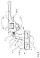
図1aは、照準方向を安定させたライフル銃を右側から示す。所定の重要な機能要素は、隠されており、破線で示される。所定の隠された要素を図示しない。2つの相互に可動な部材、前方部1及び床尾端2の間には、2つの部材に水平及び垂直に可動性を与えるヒンジ3の各部、ベアリング3が見られる。明確にする理由で、床尾端及び前方部の間の間隔は、所望の可動性を与えるために必要とされるものよりも大きくなっている。ベアリング3を介して前方部において適用されるロッド10は、床尾端において後方へ突出する。ロッドの端にはアーム8vが連結されており、それは、モーター6vの回転運動を主としてロッド10の端の直線及び垂直運動に伝達し、それにより、床尾端及び銃身の間の角度を変更する。この図において明確さを増大させるために、水平に運動を与える部材を取り除いている。床尾端の後端には突出するプレスプレート12が見られる。
FIG. 1a shows the rifle with the aiming direction stabilized from the right side. Certain important functional elements are hidden and shown in broken lines. Certain hidden elements are not shown. Between the two mutually movable members, the
図面から、特許によるライフル銃の外部構造は、ターゲット射撃のための並びに軍隊及び警察が使用するための従来のライフル銃の構造から相当の規模で異なる必要はないことがわかる。 From the drawings, it can be seen that the external structure of the patented rifle does not have to differ significantly from the conventional rifle structure for target shooting and for use by the military and police.
図1bは、照準方向を安定させたライフル銃を上から示す。隠された要素から、ロッド10とモーター6h及び6vとだけを包含する。
FIG. 1b shows the rifle with the aiming direction stabilized from above. From the hidden element, only the
図2は、照準方向を安定させたリボルバーを右手側から示す。スペースの理由で、バッテリー、電子機器、モーター及びその他の要素は、ピストルのグリップの下に固定された器具ボックスに設置される。床尾端の慣性モーメントを増大させるために、重い要素をベアリング3の遠方且つ後方に設置する。
FIG. 2 shows the revolver with the aiming direction stabilized from the right hand side. For space reasons, batteries, electronics, motors and other elements are installed in instrument boxes that are secured under the pistol grip. In order to increase the moment of inertia at the tail end of the floor, a heavy element is installed far and behind the
図3aは、どのようにモーター6h及び6vをロッド10に接続する機構を配置するかに関する原理を示す。この例において、モーターは出力シャフトにおける回転車輪とともに使用される。
FIG. 3 a shows the principle on how to arrange a mechanism for connecting the
図3bは、直線運動のモーターを使用する場合に、どのようにモーター6h及び6vをロッド10に接続するかに関する機構を配置する原理を示す。
FIG. 3b shows the principle of arranging the mechanism on how to connect the
図4において、電子部品とモーターとを水平経路において連結することを概略的に示す。垂直経路における部品は類似の方法で連結される。 FIG. 4 schematically shows the connection between the electronic component and the motor in a horizontal path. The parts in the vertical path are connected in a similar manner.
図5は、銃身及び床尾端の間のベアリングとロッド10とを示す。右側へのフランジ16は、例えばボルト継ぎ手を使って銃身1にベアリングを留めるために使われる。左側へのフランジ17は、対応する方法で床尾端にベアリングを留めるために使われる。
FIG. 5 shows the bearing and
発明にもとづいて設計されるライフル銃及び拳銃において、武器は銃身を有する前方部1及び床尾端2の2つの相互に可動な部材に分けられる。2つの部材1及び2は、共通点において互いに関して可動であり、この共通点で、それらは、カルダン継ぎ手として適切に設計される2軸ベアリングによって接続される。ベアリングは床尾端が前方部に接続するところに設置される。ベアリングは、2つの相互に直交する平面において垂直及び水平に銃身に関して支持点回りで床尾端が回転することを可能にする。
In rifles and pistols designed according to the invention, the weapon is divided into two mutually movable members, a
床尾端と銃身の向きとの間の角度は制御システム、好ましくは床尾端と銃身との間の角度を制御するサーボシステムによって調整され、銃身の向きにおける速い変化を減衰させ、これは、所望の方向を狙うこと及び弾丸を放つことを容易にする。 The angle between the floor tail and the barrel orientation is adjusted by a control system, preferably a servo system that controls the angle between the floor tail and the barrel, to attenuate fast changes in barrel orientation, Makes it easy to aim and fire bullets.
制御システム、サーボシステムは、好ましい実施形態にしたがって、
− 武器の前方部に取り付けられた2つの例えばジャイロスコープなどの角速度伝達装置であって、伝達装置がそれぞれ水平及び垂直の2平面4h及び4vそれぞれにおける回転速度を記録する、角速度伝達装置と、
− ジャイロスコープからの信号を増幅し且つフィルターにかけるバンドパスフィルターをそれぞれ有する2つの増幅器5h及び5vと、
− 増幅器5h及び5vによって制御され、床尾端に関してロッド10の後端が移動することによって床尾端と銃身との間の角度を垂直及び水平に変更できる2つの電気モーター6h及び6vと、
が含まれる。
図では、垂直方向にロッドそれによって銃身に作用するモーターを符号6vで示し、銃身の向きを水平に変更するモーターを符号6hで示す。モーターは、所望の直線運動をもたらすために異なる方法で設計されてもよい。図1a、1b、2及び3aにおける構造には、出力シャフト上で回転数を下げる歯車を有する回転モーターが示されており、回転モーターの回転運動は、モーターの出力シャフト上に取り付けられた車輪の周囲でベアリングに連結される2つのアーム8h及び8vそれぞれによって、(主に)往復運動に変換される。回転モーターに対する代替案は、図3bにもとづいた直線運動を直接もたらすリニアモーターである。モーターが回転運動を有するか直線運動を有するかに関係なく、それらをサーボモーターとして設計してもよい、すなわちモーターは、出力シャフト位置の偏位が入力信号と比例するように出力シャフト位置を制御する組込型の自動制御システムを有する。
The control system, servo system, according to a preferred embodiment,
-Two angular velocity transmission devices, such as gyroscopes, attached to the front part of the weapon, wherein the transmission devices record the rotational speeds in two horizontal and
Two
-Two
Is included.
In the figure, a motor that acts on the barrel by the rod in the vertical direction is indicated by
2つのモーター6h及び6vは、カルダン継ぎ手3における中心を貫通し且つ武器の前方部1に固定されるロッドの後端にアーム8h及び8vを介して連結され、それは、図5にもとづいて武器の前方部1に留められるカルダン継ぎ手の一部、すなわち右側に向けられるフランジ16を有する右手側部において適切に留められる。ロッドの後端をアーム8h及び8vそれぞれによって移動させると、銃身1’及び床尾端2’の間の角度は、ベアリング3において互いに関して回転する床尾端及び銃身によって変えられる。
Two
それゆえに、モーター6h、6vは、2つの部材1、2間の角度に作用する制御システムのための駆動手段を構成する。当然ながら、電気モーター以外の他の駆動手段、例えば電磁気装置または圧電装置を想定しても良い。
The
サーボシステムの機能は、銃身の長手方向の向きの変化によって、銃身方向における変化を相殺するように支持点3における角度を変えることである。発明にもとづいて設計されるライフル銃の基本機能は、以下の例によって説明される。メイン電流スイッチ14を作動させ、このようにしてサーボシステムの電子機器を始動させた後に、射手が照準を行う、すなわち武器を持ち上げ、肩に床尾端を近づけるとする。射手が床尾端を肩に接触して押し付けると、サーボシステムのモーターを作動させる電流スイッチ15が作動し、それによって、その後から銃身の照準を安定させる。さらに射手が、彼が射撃したいターゲットに狙いをつけ、且つ照準の間、彼が意図的でなく前方の銃床の周囲を保持する手、すなわち武器の前方部1の底部を下げたとする。この結果として銃身を下げ始めると、ライフル銃における回転が開始する、すなわち銃身及び床尾端1、2は、床尾端が射撃手の肩と接触する点回りにともに回転する。銃身を下げると、われわれが図1aのライフル銃を考慮する場合、回転は時計回りに向けられる。回転は、銃身の垂直な回転速度を測定するジャイロスコープ4vからの信号における変化を引き起こす。信号は、増幅器5vを介して床尾端2及び銃身1の間の角度を垂直に変えるモーター6vに作用し、ロッド10の後端は、床尾端の後端に関して下方に押し付けられ、それにより、床尾端の前部及び銃身の後端は、下に向けられる力によって作用される。ロッド10を下に押しつける力が前方部の重心に向けてではなく重心の後方の点に(図1aにおける左側へ)向けて方向付けられるので、この力は銃身1に影響する回転トルクを引き起こし、図1aにおけるそのトルクは、反時計回りの向きを有する。銃身の後端は下げられ、それによって、その向きは、照準方向を上げるように変えられ、それにより、照準方向が意図的でなく下がることは、減少または取り除かれる。このようにして、照準方向(及び射撃方向)は、射手によってそれが下げられる前の銃身の向きへの運動の速度及び大きさに応じて、多かれ少なかれ戻される。
The function of the servo system is to change the angle at the
水平方向において始められる回転において、水平面における銃身方向の調節は、サーボシステムの水平経路において対応する要素の影響を受けて行われる。 In the rotation initiated in the horizontal direction, the barrel direction adjustment in the horizontal plane is effected by the corresponding factors in the horizontal path of the servo system.
拳銃の例において、機能は、床尾端2の後端が射手の肩に接触したままではなく、それによって(相対的に)固定点に固定されないことを除いて、基本的には同じである。床尾端2が床尾端の後端回りを回転する代わりに、それはそれの質量中心、すなわちそれの重心回りを回転する傾向がある。本明細書では床尾端2と称され、且つサーボシステムの電子機器及び機構を有する部材の重量が十分に大きく、ベアリング3から十分に遠くに設置される場合、サーボシステムが稼動するときの銃身の回転トルクは、質量及び床尾端2の慣性モーメントによって銃身を安定させるのに十分に大きい。
In the pistol example, the function is basically the same except that the rear end of the
意図的でない銃身の運動、すなわちサーボシステムによって減衰させられる運動を特徴付けることは、運動が意図的な運動よりも大きい程度で高周波数成分を備えることである。サーボシステムが作動する周波数帯域を適切に選択することによって、射手は、銃身の運動におけるある慣性を観測以外の他の方法においてもサーボシステムによって妨害されることなく銃身の向きの意図的な調節をする一方で、これに反して、通常は意図しない銃身の向きの速い変化は、大きい程度で相殺且つ減衰される。 Characterizing unintentional barrel movement, that is, movement attenuated by the servo system, is that the movement has a higher frequency component to a greater extent than the intentional movement. By appropriately selecting the frequency band in which the servo system operates, the shooter can intentionally adjust the barrel orientation without disturbing the inertia of the barrel movement in other ways than by observing it. On the other hand, a quick change in the barrel direction, which is not normally intended, is offset and attenuated to a large extent.
好ましい実施形態により、角速度伝達装置からの信号は、増幅器のバンドパスフィルターにおけるハイパスフィルターによってフィルターにかけられ、そしてその後、比較的低い周波数を有する信号を抑制し、且つ、比較的高い周波数を有する信号を通過させ、銃身の向きの比較的遅い変化は、速く、通常意図的でない向きの変化と同じ高い度合いでは相殺、減衰されない。 According to a preferred embodiment, the signal from the angular velocity transmission device is filtered by a high pass filter in the amplifier band pass filter and then suppresses signals having a relatively low frequency and signals having a relatively high frequency. Passing and relatively slow changes in barrel orientation are fast and usually not offset and attenuated to the same high degree as unintentional orientation changes.
例えば実際の武器及び使用のために、銃身の運動の減衰を調節するためのハイパスフィルターにおける選択した制限周波数をハイパスフィルタリングに付与することが好ましい。 For example, for practical weapons and use, it is preferable to give the high-pass filtering a selected limiting frequency in the high-pass filter for adjusting the barrel motion attenuation.
上記の制限周波数のための望ましい間隔は、約0.5Hzから約5Hzである。 A desirable spacing for the limiting frequency is about 0.5 Hz to about 5 Hz.
サーボシステムの電子機器及びモーターは、武器13に組み込まれたバッテリーによって駆動される。武器13上に適切な配置に取り付けられるサーボシステムの電子機器における電圧をオンオフ切り替えするためのメインスイッチに加えて、プレスプレート12は、ライフル銃に含まれ、スイッチ15は、プレスプレートに接続され、且つ床尾端の端に取り付けられており、このスイッチは、サーボシステムのモーターを作動する。プレスプレートは、ばねによってその外側の位置に押し出され、射手が床尾端を肩に置くと、押される。プレスプレートがその外側の位置にあると、スイッチ15はオフに切り替えられる。サーボシステムのモーターが稼動する必須条件は、メインスイッチ14をオンにすることと、プレスプレート12を押し込み、それによってスイッチ15をオンに切り替えることと、である。それゆえに、プレスプレート12及びそれに接続されるスイッチ15は、それらの機能として、照準の間だけ、すなわちライフル銃を肩に押し付けて保持するときだけに、サーボシステムのモーターを作動して照準方向を安定させなければならない。これにより、電流の消費量は減少する。
The servo system electronics and motor are driven by a battery built into the
拳銃の例において、サーボシステムのモーターを作動するプレスプレートは、武器上の適切な位置に取り付けられたスイッチ7で置換されており、この位置では、射手が狙っているときに射手によってそれを稼動する。図2において、位置決めは、射撃に関して床尾端の後端にある押しボタンを押下することによってサーボシステムを作動することを可能にすることが明記されている。このスイッチ7の正確な位置決めは、武器構造と狙いをつけているときに手でどのようにそれが支えられるかを考慮して決定される。 In the pistol example, the press plate that operates the servo system motor has been replaced by a switch 7 mounted in the appropriate position on the weapon, where it is activated by the shooter when the shooter is aiming. To do. In FIG. 2, it is specified that positioning allows the servo system to be activated by depressing a push button at the rear end of the floor tail for shooting. The exact positioning of the switch 7 is determined taking into account the weapon structure and how it is supported by the hand when aiming.
拳銃の場合、武器において得られるスペースは、サーボシステム及び機構を収納するには十分に大きくない。このために、且つ床尾端2の慣性モーメントを増大させるために、これらの部材は、ピストルのグリップの下方及び後方に適切に設置される。可能性のある構造を図2に示す。慣性モーメントの増大により、床尾端及び銃身の間におけるある特定の角度の変化は、床尾端のより小さな回転とともに起こる。
In the case of a handgun, the space available in the weapon is not large enough to accommodate the servo system and mechanism. For this purpose and in order to increase the moment of inertia of the
上記発明は、構造例及び好ましい実施形態に関連して記載された。 The above invention has been described with reference to structural examples and preferred embodiments.
当然ながら、さらなる実施形態並びに小改正及び小規模な追加は、基礎の発明のアイディアから逸脱することなく想定されてもよい。 Of course, further embodiments and minor revisions and minor additions may be envisaged without departing from the idea of the underlying invention.
1 前方部、1’ 銃身、2 後方部、2’ 床尾端、3 ヒンジ,継ぎ手,(ベアリング,支持点)、4h 制御システム、4v 制御システム(ジャイロスコープ)、5h 制御システム,増幅器、5v 制御システム,増幅器、6h 制御システム,駆動手段,電気モーター(モーター)、6v 制御システム,駆動手段,電気モーター(モーター)、7 切替装置(スイッチ)、8h 操作要素(アーム)、8v 操作要素(アーム)、10 操作手段(ロッド)、12 切替装置(プレスプレート)、14 メインスイッチ(メイン電流スイッチ)、15 切替装置(電流スイッチ,スイッチ) 1 front part, 1 'barrel, 2 rear part, 2' floor tail end, 3 hinge, joint, (bearing, support point), 4h control system, 4v control system (gyroscope), 5h control system, amplifier, 5v control system , Amplifier, 6h control system, drive means, electric motor (motor), 6v control system, drive means, electric motor (motor), 7 switching device (switch), 8h operation element (arm), 8v operation element (arm), 10 operation means (rod), 12 switching device (press plate), 14 main switch (main current switch), 15 switching device (current switch, switch)
Claims (40)
− 前記銃身(1’)を備える武器の前方部(1)と武器の床尾端(2’)を備える武器の後方部(2)との間に、前記前方部及び前記後方部の間で相互に可動とするためにヒンジ(3)を設ける工程と、
− 少なくとも2平面において前記銃身の長手方向の運動を継続的に検知する工程と、
− 制御システム(4h、4v、5h、5v、6h、6v)を用いて前記床尾端及び前記銃身の長手方向の向きそれぞれの間の少なくとも1つの角度を制御し、前記銃身における向きの変化を相殺する工程と、
− 前記制御システムによる制御のために、前記ヒンジから伸び、前記前方部に配置され、且つ前記後方部の前記床尾端に突出する操作手段(10)を用いて前記前方部(1)及び前記後方部(2)を相互に回転させる工程と、
を備えることを特徴とする方法。 The movement of the put that weapon barrel during aiming by attenuating the influence of the movement of mainly unintentional the barrel in the direction of the barrel, a method of stabilizing,
Between the front part and the rear part between the front part (1) of the weapon with the barrel (1 ') and the rear part (2) of the weapon with the tail-end (2') of the weapon; Providing a hinge (3) to make it movable,
-Continuously detecting the longitudinal movement of the barrel in at least two planes;
-Control system (4h, 4v, 5h, 5v, 6h, 6v) to control at least one angle between each of the floor tail end and the longitudinal direction of the barrel to offset the orientation change in the barrel And a process of
The front part (1) and the rear part using operating means (10) extending from the hinge, arranged in the front part and projecting to the floor tail end of the rear part for control by the control system; Rotating the part (2) with each other;
A method comprising the steps of:
を備えることを特徴とする請求項1または2に記載の方法。 Detecting the longitudinal movement of the barrel in two mutually orthogonal planes, preferably in one substantially vertical plane and one substantially horizontal plane;
The method according to claim 1 or 2, characterized in that it comprises a.
を備えることを特徴とする請求項1から3のいずれか1項に記載の方法。 -Providing two paths of the control system, one path in a plane, thereby preferably a vertical and horizontal path, each of the two paths being means for detecting angular velocity (4h 4v) and an angular velocity transmission device associated with the longitudinal movement of the barrel in each plane,
The method according to claim 1 , comprising:
を備えることを特徴とする請求項4に記載の方法。The method of claim 4, comprising:
を備えることを特徴とする請求項5に記載の方法。The method of claim 5 comprising:
を備えることを特徴とする請求項6に記載の方法。The method of claim 6 comprising:
を備えることを特徴とする請求項7または8に記載の方法。9. The method according to claim 7 or 8, comprising:
を備えることを特徴とする請求項3から9のいずれか1項に記載の方法。 -Providing the hinge with mutual mobility in two planes that detect rotation of the barrel;
10. The method according to any one of claims 3 to 9 , comprising:
を備えることを特徴とする請求項1から10のいずれか1項に記載の方法。 -Providing the hinge as a cardan joint structure;
The method according to claim 1, any one of 10, characterized in that it comprises a.
を備えることを特徴とする請求項1から11のいずれか1項に記載の方法。 -Providing said control system as a servo system to control the angle between each of the longitudinal direction of said barrel tail and said barrel in two mutually orthogonal planes;
The method according to any one of claims 1 to 11, characterized in that it comprises.
を備えることを特徴とする請求項1に記載の方法。 -Providing the driving means (6h, 6v) at the tail end of the floor for the action of the driving means;
The method of claim 1 , comprising:
を備えることを特徴とする請求項13に記載の方法。 - to control the angle between the floor tail and the barrel in each of the vertical and horizontal directions, providing motion means driving to name the form of an electric motor for each route of said control system (6h, 6v) process ,
14. The method of claim 13 , comprising:
を備えることを特徴とする請求項14に記載の方法。 - operating element for performing a linear movement which primarily reciprocating (8h, 8v) step of reacting the motor, respectively,
15. The method of claim 14 , comprising:
を備えることを特徴とする請求項15に記載の方法。 -Providing the two motors and the operating elements and moving each operating element in two mutually orthogonal directions corresponding to the two paths;
16. The method of claim 15 , comprising:
を備えることを特徴とする請求項16に記載の方法。 -Connecting the operating element and the operating means to rotate the front part and the rear part mutually;
The method of claim 16 , comprising:
を備えることを特徴とする請求項17に記載の方法。 - applying said operation element, a predetermined portion away from the front portion of the to operation means, such a form of a rod element protruding into the bed tail end,
18. The method of claim 17 , comprising:
を備えることを特徴とする請求項1から18のいずれか1項に記載の方法。 A switching device (7, 12, 15) arranged to be operated by the person aiming, preferably, after switching on the main switch (14) for the current source of the control system when aiming ) To activate the control system using
The method according to any one of claims 1 18, characterized in that it comprises a.
− 前記銃身(1’)を備える武器の前方部(1)と武器の床尾端(2’)を備える武器の後方部(2)との間にあり、前記前方部及び前記後方部の間で相互に可動とするための継ぎ手(3)と、
− 少なくとも2平面において前記銃身の長手方向の運動を継続的に検知する装置(4h、4v)と、
− 前記銃身の向きにおける変化を妨害するように、前記床尾端及び前記銃身の長手方向の向きそれぞれの間の少なくとも1つの角度を制御するための制御システム(4h、4v、5h、5v、6h、6v)と、
を備え、
操作手段は、前記前方部(1)と前記後方部(2)とを相互に回転させるために設けられ、
前記制御システムによる制御のために前記操作手段(10)は、前記継ぎ手から伸び、前記前方部に配置され、且つ前記後方部の前記床尾端に突出することを特徴とする装置。 The movement of the put that weapon barrel during aiming by attenuating the influence of the movement of mainly unintentional the barrel in the direction of the barrel, a device to stabilize,
-Between the front part (1) of the weapon with the barrel (1 ') and the rear part (2) of the weapon with the tail-end (2') of the weapon, between the front part and the rear part A joint (3) for mutual movement;
A device (4h, 4v) for continuously detecting the longitudinal movement of the barrel in at least two planes;
A control system (4h, 4v, 5h, 5v, 6h, for controlling at least one angle between the tail-end and the longitudinal direction of the barrel, respectively, so as to prevent changes in the barrel orientation; 6v)
Equipped with a,
An operating means is provided for rotating the front part (1) and the rear part (2) relative to each other,
It said operating means for control by the control system (10) extends from said joint, being arranged on the front portion, and wherein the Rukoto to and projecting to the floor tail end of the rear portion.
請求項20から38のいずれか1項に記載の装置を備えることを特徴とする火器。 A firearm with a floor tail and a barrel,
A firearm comprising the device according to any one of claims 20 to 38 .
Applications Claiming Priority (3)
| Application Number | Priority Date | Filing Date | Title |
|---|---|---|---|
| SE0802342A SE533248C2 (en) | 2008-11-04 | 2008-11-04 | Method of gyro-stabilizing the aiming of rifles and one-handed weapons |
| SE0802342-6 | 2008-11-04 | ||
| PCT/SE2009/051249 WO2010053436A1 (en) | 2008-11-04 | 2009-11-04 | A method and a device for stabilizing aiming direction for fire arms and fire arm |
Publications (2)
| Publication Number | Publication Date |
|---|---|
| JP2012507685A JP2012507685A (en) | 2012-03-29 |
| JP5538412B2 true JP5538412B2 (en) | 2014-07-02 |
Family
ID=42153092
Family Applications (1)
| Application Number | Title | Priority Date | Filing Date |
|---|---|---|---|
| JP2011534451A Expired - Fee Related JP5538412B2 (en) | 2008-11-04 | 2009-11-04 | Method and apparatus for stabilizing aiming direction for rifles and pistols and firearms |
Country Status (8)
| Country | Link |
|---|---|
| US (1) | US8601736B2 (en) |
| EP (1) | EP2350552B1 (en) |
| JP (1) | JP5538412B2 (en) |
| KR (1) | KR101661718B1 (en) |
| CN (1) | CN102203542B (en) |
| RU (1) | RU2524492C2 (en) |
| SE (1) | SE533248C2 (en) |
| WO (1) | WO2010053436A1 (en) |
Families Citing this family (23)
| Publication number | Priority date | Publication date | Assignee | Title |
|---|---|---|---|---|
| US8635798B2 (en) | 2011-08-23 | 2014-01-28 | Tyco Electronics Corporation | Communication connector system for a weapon |
| US9146068B2 (en) | 2012-01-11 | 2015-09-29 | Dale Albert Hodgson | Motorized weapon gyroscopic stabilizer |
| US10203179B2 (en) | 2012-01-11 | 2019-02-12 | Dale Albert Hodgson | Motorized weapon gyroscopic stabilizer |
| US9354013B2 (en) | 2012-01-11 | 2016-05-31 | Dale Albert Hodgson | Motorized weapon gyroscopic stabilizer |
| US8721355B2 (en) * | 2012-02-01 | 2014-05-13 | Tyco Electronics Corporation | Electrical connector with hood |
| RU2485429C1 (en) * | 2012-03-13 | 2013-06-20 | Виталий Витальевич Бояркин | Automatic weapon with combined scheme of application (versions) |
| US8863427B2 (en) * | 2012-11-21 | 2014-10-21 | Grip Plus Inc | Automatically adjustable comb for a firearm |
| KR101299187B1 (en) * | 2013-03-19 | 2013-08-27 | 박상원 | Firearm with off-axis type stock and sight |
| US9612088B2 (en) | 2014-05-06 | 2017-04-04 | Raytheon Company | Shooting system with aim assist |
| US10408571B2 (en) | 2015-02-05 | 2019-09-10 | Raytheon Canada Limited | Switch assembly for optical sight activation |
| US9784529B1 (en) | 2015-04-07 | 2017-10-10 | Matthew G. Angle | Small arms stabilization system |
| USD804602S1 (en) | 2016-01-12 | 2017-12-05 | Magpul Industries Corp. | Firearm stock |
| WO2018005977A1 (en) | 2016-07-01 | 2018-01-04 | Vista Outdoor Operations Llc | Adjustable length bi-directional folding stock for firearm |
| USD828476S1 (en) | 2016-12-08 | 2018-09-11 | Vista Outdoor Operations Llc | Firearm stock |
| GB201700648D0 (en) * | 2017-01-13 | 2017-03-01 | Marksmanship Tech Ltd | System and method for correcting aim by motion analysis for small arms weapons |
| USD844735S1 (en) | 2017-03-07 | 2019-04-02 | Magpul Industries Corp. | Firearm stock |
| US10345076B2 (en) | 2017-03-07 | 2019-07-09 | Magpul Industries Corp. | Firearm barrel tray, stock, and related methods |
| CN111213027B (en) * | 2017-08-15 | 2023-08-04 | 帕斯帕制药有限公司 | Gun stabilizing device |
| RU2683966C1 (en) * | 2017-10-17 | 2019-04-03 | Николай Андреевич Гаврилов | Aiming method and device improving its realization |
| AU2018423158A1 (en) * | 2017-11-03 | 2020-05-21 | Aimlock Inc. | Semi-autonomous motorized weapon systems |
| US11274904B2 (en) | 2019-10-25 | 2022-03-15 | Aimlock Inc. | Remotely operable weapon mount |
| US11499791B2 (en) | 2019-10-25 | 2022-11-15 | Aimlock Inc. | Trigger and safety actuating device and method therefor |
| US11754363B1 (en) | 2020-07-29 | 2023-09-12 | Dale Albert Hodgson | Gimballed Precession Stabilization System |
Family Cites Families (14)
| Publication number | Priority date | Publication date | Assignee | Title |
|---|---|---|---|---|
| JPS61150580A (en) * | 1984-12-25 | 1986-07-09 | Matsushita Electric Ind Co Ltd | Photographic equipment |
| DE3643197A1 (en) * | 1986-12-18 | 1988-06-23 | Messerschmitt Boelkow Blohm | Aiming device for a tube weapon (weapon with a barrel) |
| US5413028A (en) * | 1993-11-12 | 1995-05-09 | Cadillac Gage Textron Inc. | Weapon stabilization system |
| FR2737001B1 (en) * | 1995-07-20 | 1997-08-29 | Giat Ind Sa | STABILIZATION DEVICE FOR INDIVIDUAL FIREARMS |
| JPH1023321A (en) * | 1996-07-05 | 1998-01-23 | Tamron Co Ltd | Image input device |
| US5974940A (en) * | 1997-08-20 | 1999-11-02 | Bei Sensors & Systems Company, Inc. | Rifle stabilization system for erratic hand and mobile platform motion |
| AT407799B (en) * | 1999-06-21 | 2001-06-25 | Ae Angerer Entpr Gmbh | RIFLE SIGHTING DEVICE |
| EP1154219A1 (en) * | 2000-05-11 | 2001-11-14 | Oerlikon Contraves Ag | Method and apparatus for correcting dynamic errors of a gun barrel |
| RU2213313C2 (en) * | 2001-11-08 | 2003-09-27 | Глухов Александр Владимирович | Feeding mechanism |
| JP2003149702A (en) * | 2001-11-19 | 2003-05-21 | Canon Inc | Optical vibration isolation unit |
| RU2237845C2 (en) * | 2002-12-10 | 2004-10-10 | Государственное унитарное предприятие "Конструкторское бюро приборостроения" | Submachine gun subbarrel grenade launcher |
| US7563097B2 (en) | 2004-09-03 | 2009-07-21 | Techno-Sciences, Inc. | Stabilizing hand grip system |
| DE102005059225B4 (en) * | 2005-12-12 | 2013-09-12 | Moog Gmbh | Weapon with a weapon barrel, which is rotatably mounted outside the center of gravity on a movable base |
| DE202008000809U1 (en) * | 2008-01-18 | 2008-03-27 | Brosinger, Andreas, Dr. | Adaptronic fire control for precision rifles |
-
2008
- 2008-11-04 SE SE0802342A patent/SE533248C2/en unknown
-
2009
- 2009-11-04 US US13/127,706 patent/US8601736B2/en active Active
- 2009-11-04 CN CN200980143992.0A patent/CN102203542B/en active Active
- 2009-11-04 WO PCT/SE2009/051249 patent/WO2010053436A1/en active Application Filing
- 2009-11-04 EP EP09825064.0A patent/EP2350552B1/en active Active
- 2009-11-04 KR KR1020117012928A patent/KR101661718B1/en active IP Right Grant
- 2009-11-04 RU RU2011122682/11A patent/RU2524492C2/en active
- 2009-11-04 JP JP2011534451A patent/JP5538412B2/en not_active Expired - Fee Related
Also Published As
| Publication number | Publication date |
|---|---|
| US20120030984A1 (en) | 2012-02-09 |
| CN102203542B (en) | 2014-03-12 |
| RU2011122682A (en) | 2012-12-20 |
| EP2350552A4 (en) | 2014-01-15 |
| KR101661718B1 (en) | 2016-09-30 |
| SE533248C2 (en) | 2010-07-27 |
| CN102203542A (en) | 2011-09-28 |
| JP2012507685A (en) | 2012-03-29 |
| RU2524492C2 (en) | 2014-07-27 |
| WO2010053436A1 (en) | 2010-05-14 |
| EP2350552B1 (en) | 2016-09-28 |
| US8601736B2 (en) | 2013-12-10 |
| SE0802342A1 (en) | 2010-05-05 |
| KR20110094036A (en) | 2011-08-19 |
| EP2350552A1 (en) | 2011-08-03 |
Similar Documents
| Publication | Publication Date | Title |
|---|---|---|
| JP5538412B2 (en) | Method and apparatus for stabilizing aiming direction for rifles and pistols and firearms | |
| US9395155B1 (en) | Active stabilization targeting correction for handheld firearms | |
| US9010002B2 (en) | Method and accessory device to improve performances of ballistic throwers | |
| KR101081214B1 (en) | Multi Purpose Remote Weapon System | |
| KR101932544B1 (en) | Remote-weapon apparatus and control method thereof | |
| US20120286041A1 (en) | Apparatus for synthetic weapon stabilization and firing | |
| US10309745B2 (en) | Mobile turret weapon delivery system | |
| KR20100102373A (en) | Remote shooting system | |
| US10890407B1 (en) | Dual remote control and crew-served weapon station | |
| KR101865535B1 (en) | Devices for fixing firearms | |
| KR20100096518A (en) | Remote shooting system | |
| JPH0755395A (en) | Silencer of gun barrel arms | |
| AU2022275071A1 (en) | A firearm trigger control device | |
| US20110000123A1 (en) | Quick Laser Modification Kit | |
| CN210242573U (en) | Small ground unmanned combat platform for mounting light weapons | |
| KR20150034974A (en) | Guns of a warship movement device for the horizontally transport | |
| RU2581885C1 (en) | Missile and artillery of anti-aircraft installation | |
| RU2813397C1 (en) | Combat module of robotic complex with remote guidance and firing | |
| CN216205664U (en) | Mortar multi-gauge setting device | |
| KR200417146Y1 (en) | Addition apparatus for field firing of rifle | |
| EP3596422B1 (en) | Arrangement for reducing recoiling forces on a sight or other component mounted on a barrel of a weapon | |
| KR20140026077A (en) | Remote weapon system and controlling method of the same | |
| RU2255286C1 (en) | Cushioning system of tank gun trunnion pins | |
| RU2222759C2 (en) | Rocket launcher | |
| CN117006891A (en) | Two-degree-of-freedom firearm remote control platform with buffering function |
Legal Events
| Date | Code | Title | Description |
|---|---|---|---|
| A621 | Written request for application examination |
Free format text: JAPANESE INTERMEDIATE CODE: A621 Effective date: 20121019 |
|
| A977 | Report on retrieval |
Free format text: JAPANESE INTERMEDIATE CODE: A971007 Effective date: 20131126 |
|
| A131 | Notification of reasons for refusal |
Free format text: JAPANESE INTERMEDIATE CODE: A131 Effective date: 20131203 |
|
| A521 | Request for written amendment filed |
Free format text: JAPANESE INTERMEDIATE CODE: A523 Effective date: 20140218 |
|
| TRDD | Decision of grant or rejection written | ||
| A01 | Written decision to grant a patent or to grant a registration (utility model) |
Free format text: JAPANESE INTERMEDIATE CODE: A01 Effective date: 20140331 |
|
| R150 | Certificate of patent or registration of utility model |
Ref document number: 5538412 Country of ref document: JP Free format text: JAPANESE INTERMEDIATE CODE: R150 |
|
| A61 | First payment of annual fees (during grant procedure) |
Free format text: JAPANESE INTERMEDIATE CODE: A61 Effective date: 20140428 |
|
| R250 | Receipt of annual fees |
Free format text: JAPANESE INTERMEDIATE CODE: R250 |
|
| R250 | Receipt of annual fees |
Free format text: JAPANESE INTERMEDIATE CODE: R250 |
|
| R250 | Receipt of annual fees |
Free format text: JAPANESE INTERMEDIATE CODE: R250 |
|
| R250 | Receipt of annual fees |
Free format text: JAPANESE INTERMEDIATE CODE: R250 |
|
| R250 | Receipt of annual fees |
Free format text: JAPANESE INTERMEDIATE CODE: R250 |
|
| R250 | Receipt of annual fees |
Free format text: JAPANESE INTERMEDIATE CODE: R250 |
|
| LAPS | Cancellation because of no payment of annual fees |