CN210242573U - Small ground unmanned combat platform for mounting light weapons - Google Patents
Small ground unmanned combat platform for mounting light weapons Download PDFInfo
- Publication number
- CN210242573U CN210242573U CN201920684716.6U CN201920684716U CN210242573U CN 210242573 U CN210242573 U CN 210242573U CN 201920684716 U CN201920684716 U CN 201920684716U CN 210242573 U CN210242573 U CN 210242573U
- Authority
- CN
- China
- Prior art keywords
- pitching
- platform
- fixed
- weapon
- ground unmanned
- Prior art date
- Legal status (The legal status is an assumption and is not a legal conclusion. Google has not performed a legal analysis and makes no representation as to the accuracy of the status listed.)
- Active
Links
Images


Abstract
The utility model discloses a small ground unmanned combat platform for hanging and carrying light weapons, which comprises a vehicle body, a circumferential mechanism, a pitching mechanism, a hanging weapon, a clamping mechanism and a detection aiming mechanism; the circumferential mechanism is arranged at the upper end of the vehicle body and is used for driving the pitching mechanism to circumferentially run relative to the vehicle body so as to drive the mounted weapon to circumferentially run; the pitching mechanism is arranged at the upper end of the circumferential mechanism; the device is used for driving the mounted weapon to do pitching motion; the mounted weapon is fixed through a clamping mechanism; the clamping mechanism is fixed with the pitching mechanism; the detection aiming mechanism is connected with a barrel of the mounted weapon; the utility model discloses can realize unmanned combat platform's miniaturization.
Description
Technical Field
The utility model belongs to unmanned combat equipment field, especially a carry small-size ground unmanned combat platform of light arms.
Background
In recent years, unmanned equipment such as unmanned aerial vehicles, unmanned submarines, unmanned combat robots and the like are rapidly developed and applied to actual combat, and become important attack and defense forces on information-based battlefields. One of the important directions is that the ground unmanned vehicle carries the weapon.
At present, in the aspect of a ground unmanned combat platform, most of domestic and foreign design experiences are large-scale platforms, the mass of the large-scale platforms is hundreds of kilograms, a mounted weapon is a heavy machine gun or a grenade launcher, and a more classical unmanned platform comprises a Gladiator (fighter) robot, a Russian platform-M robot and the like. In addition, in the aspect of small-sized platforms, non-combat tasks such as reconnaissance and explosion elimination are often designed, and reconnaissance and attack cannot be integrated.
When an anti-terrorist combat mission or an urban combat mission is executed, a large platform with heavy fire cannot be rapidly deployed and moved, the concealment is poor, and a small platform lacks a fire output means, so that a reconnaissance and striking integrated function on a small ground platform is extremely necessary.
SUMMERY OF THE UTILITY MODEL
An object of the utility model is to provide a carry light arms's unmanned platform of fighting on small-size ground to realize the miniaturization of unmanned platform of fighting.
Realize the utility model discloses the technical solution of purpose does:
a small ground unmanned combat platform for mounting a light weapon comprises a vehicle body, a circumferential mechanism, a pitching mechanism, a mounted weapon, a clamping mechanism and a detection aiming mechanism;
the circumferential mechanism is arranged at the upper end of the vehicle body and is used for driving the pitching mechanism to circumferentially run relative to the vehicle body so as to drive the mounted weapon to circumferentially run; the pitching mechanism is arranged at the upper end of the circumferential mechanism; the device is used for driving the mounted weapon to do pitching motion; the mounted weapon is fixed through a clamping mechanism; the clamping mechanism is fixed with the pitching mechanism; the detection aiming mechanism is connected with a barrel of the mounted weapon.
Compared with the prior art, the utility model, it is showing the advantage and is:
(1) the utility model discloses an unmanned combat platform has realized guaranteeing the miniaturization of platform under reconnaissance, the firepower function prerequisite, and the mechanism is simple relatively, and volume, quality are littleer, are fit for individual soldier or team and carry, and mobility is high.
(2) The utility model discloses an unmanned platform of fighting can realize the regulation of weapon shooting angle of pitch, circumference shooting direction, and the shooting range is wide, and the flexibility is good.
(3) This unmanned combat platform passes through fixture and buffer gear, can realize keeping the weapon muzzle to beat less and the platform stable circumstances under the continuous shooting, and platform stability and reliability are outstanding.
Drawings
Fig. 1 is a schematic view of the overall structure of the present invention.
FIG. 2 is a schematic view of the clamping mechanism coupled to a mounted weapon.
Fig. 3 is a top view of the structure of the buffer mechanism.
Fig. 4 is a schematic view of the connection between the pitching mechanism and the clamping mechanism.
Fig. 5 is a schematic view of the connection between the holder base and the vehicle body.
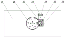
FIG. 6 is a bottom view of the connection of the circumferential mechanism to the vehicle head.
FIG. 7 is a schematic view of a circumferential mechanism rotating shaft connection.
Fig. 8 is a schematic view of the connection between the detection aiming mechanism and the barrel.
Detailed Description
The present invention will be further described with reference to the accompanying drawings and specific embodiments.
The utility model relates to a small ground unmanned combat platform for carrying small arms, which comprises a vehicle body 30, a circumferential mechanism, a pitching mechanism, a carrying arm 1, a clamping mechanism and a detecting and aiming mechanism;
the circumferential mechanism is arranged at the upper end of the vehicle body 30 and is used for driving the pitching mechanism to circumferentially run relative to the vehicle body 30 so as to drive the mounted weapon 1 to circumferentially run; the pitching mechanism is arranged at the upper end of the circumferential mechanism; used for driving the mounted weapon 1 to perform pitching motion; the hanging weapon 1 is fixed through a clamping mechanism; the clamping mechanism is fixed with the pitching mechanism; the detection aiming mechanism is connected with a barrel of the mounted weapon 1 and moves along with the barrel so as to realize the detection of the unmanned combat platform on the environment and the aiming of the mounted weapon 1 on the target.
Further, the clamping mechanism comprises a pipe clamp 2, a connecting plate 3, a connecting block 5, a rubber block 4 and a rubber pad 6; the two pipe clamps 2 are respectively arranged at the left end and the right end of the gun barrel, and the gun barrel is clamped and fixed after the two pipe clamps 2 are fixed; the rear end of the mounted weapon 1 is provided with a connecting block 5; connecting plates 3 are respectively arranged on two sides of the mounted weapon 1; the front ends of the two connecting plates 3 are fixedly connected with the pipe clamps 2 on the corresponding sides respectively, and the rear ends of the two connecting plates are fixedly connected with the connecting blocks 5; the rubber pad 6 is arranged between the connecting block 5 and the gun handle; the connecting block 5 is provided with an adjusting screw; the adjusting screw penetrates through the connecting block 5 to abut against the rubber pad 6, so that the weapon 1 is fixed at the rear; rubber blocks 4 are arranged between the two pipe clamps 2 and between the connecting plate 3 and the pipe clamps 2 for filling. By means of the mode, the hanging weapon 1 can be guaranteed not to generate undesirable vibration or fall off relative to the clamping mechanism when being launched, and the reduction of shooting precision caused by the undesirable vibration or fall off is avoided. Meanwhile, the position of the rubber pad 6 can be adjusted through the adjusting screw, so that the device is suitable for different types of mounted weapons 1.
Furthermore, the clamping mechanism is also connected with the pitching mechanism through a buffer mechanism; the buffer mechanism comprises a limiting block 7, a guide rod 8, a buffer spring 9 and a sliding block 11; limiting blocks 7 are fixed at the front end and the rear end of the connecting plate 3; a guide rod 7 is fixed between the two limiting blocks 7 on the same side; the sliding block 11 is arranged on the guide rod 7; the front end and the rear end of the sliding block 11 are both provided with buffer springs 9; the buffer spring 8 is sleeved on the guide rod 7, one end of the buffer spring 8 is in contact with the limiting block 7, and the other end of the buffer spring is in contact with the sliding block 11; the slider 11 is connected with a pitching mechanism. When shooting, receive the influence of carrying weapon 1 recoil, whole fixture can backward motion, and the buffering spring 9 in rear receives the extrusion to absorb some energy to promote the clamping part and move forward and extrude the buffering spring 9 in the place ahead, the buffering spring 9 in rear plays the cushioning effect, and the buffering spring 9 in place ahead plays the effect of resetting, so relapse, can realize buffering absorbing effect.
Further, the pitching mechanism comprises a pitching supporting shaft 10, a holder base 16 and a pitching motor 15; the holder base 16 is a U-shaped support structure; the mounted weapon 1 is positioned in the holder base 16; both sides of the upper end of the holder base 16 are provided with pitching supporting shafts 10; the pitching supporting shaft 10 is connected with a sliding block 11 on the corresponding side; the pitching motor 15 is fixed with the holder base 16 through connecting pieces 13 and 14; the output shaft of the pitch motor 15 is connected with the pitch support shaft 10. The pitching motor 15 rotates to drive the pitching supporting shaft 10 to rotate, the pitching supporting shaft 10 rotates to drive the clamping mechanism to rotate through the buffer mechanism, and the mounted weapon 1 is further driven to perform pitching motion.
Furthermore, the two sliding blocks 11 are connected through a connecting piece 12; the link keeps the two sliders 11 sliding synchronously while keeping the two pitch support shafts 10 connected to the sliders 11 coaxial.
Further, the circumferential mechanism comprises a rotating shaft 19, a rotating disc 20, a driven gear 21, a driving gear 22 and a rotating motor 24; the rotating motor 24 is fixed at the lower end of the top plate 17 of the vehicle body 30 through a clamp 23 and a connecting piece 25/26; the output shaft of the rotating motor 24 is connected with the driving gear 22; the driving gear 22 is meshed with the driven gear 21; the transmission gearwheel 21 is fixedly connected with the lower end of the rotating shaft 19; the rotating shaft 19 is supported on the top plate 17 through a bearing; the turntable 20 comprises an inner ring and an outer ring, and the inner ring is fixed at the upper end of the top plate 17; the lower end of the outer ring is fixedly connected with the rotating shaft 19, and the upper end of the outer ring is fixedly connected with the holder base 16.
Further, the rotating shaft 19 is a hollow shaft to mount the conductive slip ring 18 to avoid winding of the wire.
Further, the detection aiming mechanism comprises a camera 27, a fixed pipe clamp 28 and a laser emitter 29; the camera 27 and the laser emitter 29 are both fixed with a barrel of the weapon 1 through a fixed pipe clamp 28; the camera 27 is used for collecting an image of the mounted weapon 1 with the muzzle pointing to the front; the laser emitter 29 is used for collecting the impact point to judge the approximate range of the impact point of the weapon after shooting, so as to adjust the angles of the circumferential mechanism and the pitching mechanism and realize the control of the shooting precision.
Furthermore, the parts such as the holder base and the gear are all hollow structures, so that the center of gravity moves down and stays in the center as far as possible, and the stability of the unmanned platform during working is ensured.
The utility model discloses an unmanned combat platform can carry on light arms such as submachine-gun, machine gun, and ground unmanned platform carries on the weapon and firmly links together with unmanned vehicle under the fixture effect when marcing. When an operator finds a target through a camera system on a vehicle and needs to aim at shooting, the pitching motor 15 in the pitching mechanism is controlled by the pitching control handle on the control handle, the motor drives the pitching support shaft 10 to rotate together during working, and the clamping mechanism also rotates along with the pitching support shaft, so that the motor can adjust the pitching angle of the fixed firearm, and the aiming action in the vertical direction is completed. The rotating motor 24 in the circumferential mechanism is controlled to work by operating the circumferential control handle on the control handle, so that the rotating shaft 19 rotates to drive the circumferential rotation of the holder base 16 on the unmanned platform, and the circumferential angle is adjusted.
Claims (8)
1. A small ground unmanned combat platform for carrying small arms is characterized by comprising a vehicle body (30), a circumferential mechanism, a pitching mechanism, a carrying arm (1), a clamping mechanism and a detection aiming mechanism;
the circumferential mechanism is arranged at the upper end of the vehicle body (30) and is used for driving the pitching mechanism to circumferentially run relative to the vehicle body (30) so as to drive the mounted weapon (1) to circumferentially run; the pitching mechanism is arranged at the upper end of the circumferential mechanism; the device is used for driving the mounted weapon (1) to do pitching motion; the hanging weapon (1) is fixed through a clamping mechanism; the clamping mechanism is fixed with the pitching mechanism; the detection aiming mechanism is connected with a barrel of the mounted weapon (1).
2. The small ground unmanned aerial vehicle (SMV) platform of claim 1, wherein the clamping mechanism comprises a pipe clamp (2), a connecting plate (3), a connecting block (5), a rubber block (4) and a rubber pad (6); the two pipe clamps (2) are respectively arranged at the left end and the right end of the gun barrel; the rear end of the mounted weapon (1) is provided with a connecting block (5); connecting plates (3) are respectively arranged on two sides of the mounted weapon (1); the front ends of the two connecting plates (3) are fixedly connected with the pipe clamps (2) on the corresponding sides respectively, and the rear ends of the two connecting plates are fixedly connected with the connecting blocks (5); the rubber pad (6) is arranged between the connecting block (5) and the gun handle; the connecting block (5) is provided with an adjusting screw; the adjusting screw penetrates through the connecting block (5) to prop against the rubber pad (6); rubber blocks (4) are arranged between the two pipe clamps (2) and between the connecting plate (3) and the pipe clamps (2) for filling.
3. The small ground unmanned aerial vehicle (SMV) platform of claim 2, wherein the clamping mechanism is further coupled to the pitching mechanism via a damping mechanism; the buffer mechanism comprises a limit block (7), a guide rod (8), a buffer spring (9) and a slide block (11); limiting blocks (7) are fixed at the front end and the rear end of the connecting plate (3); a guide rod (8) is fixed between the two limiting blocks (7) on the same side; the sliding block (11) is arranged on the guide rod (8); the front end and the rear end of the sliding block (11) are provided with buffer springs (9); the buffer spring (9) is sleeved on the guide rod (8), one end of the buffer spring (9) is in contact with the limiting block (7), and the other end of the buffer spring is in contact with the sliding block (11).
4. The small-sized ground unmanned aerial vehicle platform for carrying small arms according to claim 3, wherein the two sliding blocks (11) are connected with each other through a connecting member (12).
5. The small ground unmanned aerial vehicle (SMV) platform of claim 1, wherein the pitch mechanism comprises a pitch support shaft (10), a pan and tilt head base (16), a pitch motor (15); the holder base (16) is of a U-shaped support structure; the hanging weapon (1) is positioned in the holder base (16); both sides of the upper end of the holder base (16) are provided with pitching supporting shafts (10); the pitching supporting shaft (10) is connected with the sliding block (11) on the corresponding side; the pitching motor (15) is fixed with the holder base (16); the output shaft of the pitching motor (15) is connected with the pitching supporting shaft (10).
6. The small ground unmanned aerial vehicle (SMV) platform of claim 1, wherein the circumferential mechanism comprises a rotating shaft (19), a turntable (20), a driven gear (21), a driving gear (22), a rotating motor (24); the rotating motor (24) is fixed at the lower end of a top plate (17) of the vehicle body (30); the output shaft of the rotating motor (24) is connected with the driving gear (22); the driving gear (22) is meshed with the driven gear (21); the driven gear (21) is fixedly connected with the lower end of the rotating shaft (19); the rotating shaft (19) is supported on the top plate (17) through a bearing; the turntable (20) comprises an inner ring and an outer ring, and the inner ring is fixed at the upper end of the top plate (17); the lower end of the outer ring is fixedly connected with a rotating shaft (19), and the upper end of the outer ring is fixedly connected with a holder base (16).
7. The small ground unmanned aerial vehicle (SMV) platform of claim 6, wherein the rotating shaft (19) is a hollow shaft for mounting an electrically conductive slip ring (18).
8. The small ground unmanned aerial vehicle (SMV) platform of claim 1, wherein the detection aiming mechanism comprises a camera (27), a fixed pipe clamp (28) and a laser emitter (29); the camera (27) and the laser emitter (29) are both fixed with a barrel of the mounted weapon (1) through a fixed pipe clamp (28); the camera (27) is used for collecting an image of the mounted weapon (1) with the muzzle pointing to the front; the laser emitter (29) is used for collecting an impact point.
Priority Applications (1)
| Application Number | Priority Date | Filing Date | Title |
|---|---|---|---|
| CN201920684716.6U CN210242573U (en) | 2019-05-14 | 2019-05-14 | Small ground unmanned combat platform for mounting light weapons |
Applications Claiming Priority (1)
| Application Number | Priority Date | Filing Date | Title |
|---|---|---|---|
| CN201920684716.6U CN210242573U (en) | 2019-05-14 | 2019-05-14 | Small ground unmanned combat platform for mounting light weapons |
Publications (1)
| Publication Number | Publication Date |
|---|---|
| CN210242573U true CN210242573U (en) | 2020-04-03 |
Family
ID=69970860
Family Applications (1)
| Application Number | Title | Priority Date | Filing Date |
|---|---|---|---|
| CN201920684716.6U Active CN210242573U (en) | 2019-05-14 | 2019-05-14 | Small ground unmanned combat platform for mounting light weapons |
Country Status (1)
| Country | Link |
|---|---|
| CN (1) | CN210242573U (en) |
Cited By (1)
| Publication number | Priority date | Publication date | Assignee | Title |
|---|---|---|---|---|
| CN110095024A (en) * | 2019-05-14 | 2019-08-06 | 南京理工大学 | A kind of small ground unmanned fighting platform of carry small arms |
-
2019
- 2019-05-14 CN CN201920684716.6U patent/CN210242573U/en active Active
Cited By (1)
| Publication number | Priority date | Publication date | Assignee | Title |
|---|---|---|---|---|
| CN110095024A (en) * | 2019-05-14 | 2019-08-06 | 南京理工大学 | A kind of small ground unmanned fighting platform of carry small arms |
Similar Documents
| Publication | Publication Date | Title |
|---|---|---|
| JP5538412B2 (en) | Method and apparatus for stabilizing aiming direction for rifles and pistols and firearms | |
| US8082836B2 (en) | Mitigating recoil in a ballistic robot | |
| CN110095024A (en) | A kind of small ground unmanned fighting platform of carry small arms | |
| CN108195227B (en) | Gun clamping mechanism with spring buffer device assembled on unmanned aerial vehicle | |
| CN210242573U (en) | Small ground unmanned combat platform for mounting light weapons | |
| US9777976B2 (en) | Spent cartridges router | |
| CN209441659U (en) | A kind of unmanned plane carry percussion platform mechanism suitable for 92 formula pistols | |
| CN210338278U (en) | Unmanned plane | |
| CN110906785B (en) | Robot for controlling rifle shooting | |
| US5945625A (en) | Tank turret | |
| KR100369531B1 (en) | machine gun supporter | |
| KR20110111728A (en) | Movable gunshot test device | |
| CN219284114U (en) | Weapon station and small-sized unmanned vehicle | |
| CN115046423B (en) | Light weapon arm device | |
| CN209988130U (en) | Unmanned aerial vehicle weapon mounting system and unmanned aerial vehicle | |
| CN208155144U (en) | A kind of gun clamping device with spring bumper being assemblied in unmanned plane | |
| CN114034208A (en) | Coil bottom pushing type electromagnetic gun and pitching adjusting device thereof | |
| CN209988131U (en) | Launch rifle and unmanned aerial vehicle | |
| CN208915450U (en) | A kind of firing angle control mechanism of the low recoil carry platform of small drone | |
| CN218055629U (en) | Unmanned aerial vehicle cloud platform mechanism of carry grenade transmitter | |
| CN205279873U (en) | Elasticity projection unit closely | |
| CN117006891A (en) | Two-degree-of-freedom firearm remote control platform with buffering function | |
| CN215930681U (en) | A firearms mount for unmanned equipment | |
| CN109470083B (en) | Universal tube-turning machine gun weapon station | |
| CN219531814U (en) | Police unmanned equipment firearm fixing frame |
Legal Events
| Date | Code | Title | Description |
|---|---|---|---|
| GR01 | Patent grant | ||
| GR01 | Patent grant |