JP5528327B2 - Apparatus and method for controlling power shunt, and hybrid vehicle having the same circuit - Google Patents
Apparatus and method for controlling power shunt, and hybrid vehicle having the same circuit Download PDFInfo
- Publication number
- JP5528327B2 JP5528327B2 JP2010506976A JP2010506976A JP5528327B2 JP 5528327 B2 JP5528327 B2 JP 5528327B2 JP 2010506976 A JP2010506976 A JP 2010506976A JP 2010506976 A JP2010506976 A JP 2010506976A JP 5528327 B2 JP5528327 B2 JP 5528327B2
- Authority
- JP
- Japan
- Prior art keywords
- generator
- motor
- controlling
- chopping
- inverter
- Prior art date
- Legal status (The legal status is an assumption and is not a legal conclusion. Google has not performed a legal analysis and makes no representation as to the accuracy of the status listed.)
- Active
Links
- 238000000034 method Methods 0.000 title claims description 6
- 239000003990 capacitor Substances 0.000 claims description 19
- 238000001514 detection method Methods 0.000 claims description 8
- 238000002485 combustion reaction Methods 0.000 claims description 7
- 238000001914 filtration Methods 0.000 claims description 7
- 238000006243 chemical reaction Methods 0.000 claims description 3
- 238000010586 diagram Methods 0.000 description 3
- 230000032683 aging Effects 0.000 description 2
- 230000001174 ascending effect Effects 0.000 description 2
- 239000000969 carrier Substances 0.000 description 2
- 238000010438 heat treatment Methods 0.000 description 2
- 239000004020 conductor Substances 0.000 description 1
- 238000011217 control strategy Methods 0.000 description 1
- 229940061368 sonata Drugs 0.000 description 1
- 238000001228 spectrum Methods 0.000 description 1
- 230000007704 transition Effects 0.000 description 1
Images


Classifications
-
- H—ELECTRICITY
- H02—GENERATION; CONVERSION OR DISTRIBUTION OF ELECTRIC POWER
- H02M—APPARATUS FOR CONVERSION BETWEEN AC AND AC, BETWEEN AC AND DC, OR BETWEEN DC AND DC, AND FOR USE WITH MAINS OR SIMILAR POWER SUPPLY SYSTEMS; CONVERSION OF DC OR AC INPUT POWER INTO SURGE OUTPUT POWER; CONTROL OR REGULATION THEREOF
- H02M7/00—Conversion of ac power input into dc power output; Conversion of dc power input into ac power output
- H02M7/42—Conversion of dc power input into ac power output without possibility of reversal
- H02M7/44—Conversion of dc power input into ac power output without possibility of reversal by static converters
- H02M7/48—Conversion of dc power input into ac power output without possibility of reversal by static converters using discharge tubes with control electrode or semiconductor devices with control electrode
- H02M7/53—Conversion of dc power input into ac power output without possibility of reversal by static converters using discharge tubes with control electrode or semiconductor devices with control electrode using devices of a triode or transistor type requiring continuous application of a control signal
- H02M7/537—Conversion of dc power input into ac power output without possibility of reversal by static converters using discharge tubes with control electrode or semiconductor devices with control electrode using devices of a triode or transistor type requiring continuous application of a control signal using semiconductor devices only, e.g. single switched pulse inverters
- H02M7/5387—Conversion of dc power input into ac power output without possibility of reversal by static converters using discharge tubes with control electrode or semiconductor devices with control electrode using devices of a triode or transistor type requiring continuous application of a control signal using semiconductor devices only, e.g. single switched pulse inverters in a bridge configuration
- H02M7/53871—Conversion of dc power input into ac power output without possibility of reversal by static converters using discharge tubes with control electrode or semiconductor devices with control electrode using devices of a triode or transistor type requiring continuous application of a control signal using semiconductor devices only, e.g. single switched pulse inverters in a bridge configuration with automatic control of output voltage or current
-
- B—PERFORMING OPERATIONS; TRANSPORTING
- B60—VEHICLES IN GENERAL
- B60L—PROPULSION OF ELECTRICALLY-PROPELLED VEHICLES; SUPPLYING ELECTRIC POWER FOR AUXILIARY EQUIPMENT OF ELECTRICALLY-PROPELLED VEHICLES; ELECTRODYNAMIC BRAKE SYSTEMS FOR VEHICLES IN GENERAL; MAGNETIC SUSPENSION OR LEVITATION FOR VEHICLES; MONITORING OPERATING VARIABLES OF ELECTRICALLY-PROPELLED VEHICLES; ELECTRIC SAFETY DEVICES FOR ELECTRICALLY-PROPELLED VEHICLES
- B60L50/00—Electric propulsion with power supplied within the vehicle
- B60L50/50—Electric propulsion with power supplied within the vehicle using propulsion power supplied by batteries or fuel cells
- B60L50/51—Electric propulsion with power supplied within the vehicle using propulsion power supplied by batteries or fuel cells characterised by AC-motors
-
- H—ELECTRICITY
- H02—GENERATION; CONVERSION OR DISTRIBUTION OF ELECTRIC POWER
- H02M—APPARATUS FOR CONVERSION BETWEEN AC AND AC, BETWEEN AC AND DC, OR BETWEEN DC AND DC, AND FOR USE WITH MAINS OR SIMILAR POWER SUPPLY SYSTEMS; CONVERSION OF DC OR AC INPUT POWER INTO SURGE OUTPUT POWER; CONTROL OR REGULATION THEREOF
- H02M5/00—Conversion of ac power input into ac power output, e.g. for change of voltage, for change of frequency, for change of number of phases
- H02M5/40—Conversion of ac power input into ac power output, e.g. for change of voltage, for change of frequency, for change of number of phases with intermediate conversion into dc
- H02M5/42—Conversion of ac power input into ac power output, e.g. for change of voltage, for change of frequency, for change of number of phases with intermediate conversion into dc by static converters
- H02M5/44—Conversion of ac power input into ac power output, e.g. for change of voltage, for change of frequency, for change of number of phases with intermediate conversion into dc by static converters using discharge tubes or semiconductor devices to convert the intermediate dc into ac
- H02M5/453—Conversion of ac power input into ac power output, e.g. for change of voltage, for change of frequency, for change of number of phases with intermediate conversion into dc by static converters using discharge tubes or semiconductor devices to convert the intermediate dc into ac using devices of a triode or transistor type requiring continuous application of a control signal
- H02M5/458—Conversion of ac power input into ac power output, e.g. for change of voltage, for change of frequency, for change of number of phases with intermediate conversion into dc by static converters using discharge tubes or semiconductor devices to convert the intermediate dc into ac using devices of a triode or transistor type requiring continuous application of a control signal using semiconductor devices only
- H02M5/4585—Conversion of ac power input into ac power output, e.g. for change of voltage, for change of frequency, for change of number of phases with intermediate conversion into dc by static converters using discharge tubes or semiconductor devices to convert the intermediate dc into ac using devices of a triode or transistor type requiring continuous application of a control signal using semiconductor devices only having a rectifier with controlled elements
-
- Y—GENERAL TAGGING OF NEW TECHNOLOGICAL DEVELOPMENTS; GENERAL TAGGING OF CROSS-SECTIONAL TECHNOLOGIES SPANNING OVER SEVERAL SECTIONS OF THE IPC; TECHNICAL SUBJECTS COVERED BY FORMER USPC CROSS-REFERENCE ART COLLECTIONS [XRACs] AND DIGESTS
- Y02—TECHNOLOGIES OR APPLICATIONS FOR MITIGATION OR ADAPTATION AGAINST CLIMATE CHANGE
- Y02T—CLIMATE CHANGE MITIGATION TECHNOLOGIES RELATED TO TRANSPORTATION
- Y02T10/00—Road transport of goods or passengers
- Y02T10/60—Other road transportation technologies with climate change mitigation effect
- Y02T10/70—Energy storage systems for electromobility, e.g. batteries
Landscapes
- Engineering & Computer Science (AREA)
- Power Engineering (AREA)
- Life Sciences & Earth Sciences (AREA)
- Sustainable Development (AREA)
- Sustainable Energy (AREA)
- Transportation (AREA)
- Mechanical Engineering (AREA)
- Electric Propulsion And Braking For Vehicles (AREA)
- Control Of Eletrric Generators (AREA)
- Inverter Devices (AREA)
Abstract
Description
本発明は、ハイブリッド車両の電力分路を制御するための装置に関する。 The present invention relates to an apparatus for controlling a power shunt of a hybrid vehicle.
本発明の一応用分野は、ハイブリッド陸路用車両である。 One field of application of the present invention is hybrid land vehicle.
特許文献1は、DC側がDC電圧保存ユニットに接続され且つAC側が車両の機械的ドライブに結合されるように設計された第1及び第2多相電気機器に接続される第1及び第2インバーターを備える装置について記載している。第1機器はモーターとして動作することができ、第2機器はドライブからの電力を分路するための発電機として動作することができ、上記インバーターはさらに、DC側とAC側の間の変換のためのチョッピングスイッチを備え、且つこの装置は、インバーターのDC側において高調波をろ過するためのコンデンサーと、チョッピングスイッチを制御するためのユニットとを備え、該ユニットは、インバーター用と同じ周波数を持つ搬送波のパルス幅変調によって該チョッピングスイッチを制御するためのモードを有する。 Patent Document 1 discloses first and second inverters connected to first and second multiphase electrical devices designed such that the DC side is connected to a DC voltage storage unit and the AC side is coupled to a mechanical drive of a vehicle. Is described. The first device can operate as a motor, the second device can operate as a generator for shunting power from the drive, and the inverter further converts between the DC side and the AC side. And a device for filtering harmonics on the DC side of the inverter and a unit for controlling the chopping switch, the unit having the same frequency as for the inverter There is a mode for controlling the chopping switch by pulse width modulation of the carrier wave.
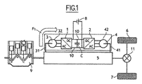
電力分路を持つハイブリッド車両に公知であり、図1に示されるように、二つの電気機器3、4の一方の側は車輪6、7に接続される機械的ドライブ5に、且つその他方の側は電力保存システム8に接続される。二つのインバーター1、2は機器3、4を制御するために使用される。ドライブ5が車両の内燃機関9によって駆動される場合、ドライブ5からの電力を分路するために、機器の内の一つはモーターとして動作し、他方は発電機として動作しなければならない。内燃機関がスイッチオフされると、二つの機器3、4の内の一方が、ドライブを動作させるために使用される。
Known to hybrid vehicles with a power shunt, as shown in FIG. 1, one side of two electrical devices 3, 4 is connected to a
共通のろ過コンデンサーCは、通常、二つのインバーター1、2の間のDCバス10に登載される。
The common filtration capacitor C is usually mounted on the
インバーター1、2は、そのDC電圧スイッチを開放及び閉鎖することによってチョッピングすることによってAC電圧を生成し、この電圧は機器3、4に供給される。これは、MLI(パルス幅変調)チョッピングと呼ばれる。
The
この高周波(数kHz)チョッピングは、機器の電流に、有効な基本波に加えて高周波を生成し、同様に、DCバス10において生成される電流のスペクトラルを広げる。
This high frequency (several kHz) chopping generates a high frequency in addition to an effective fundamental wave to the device current, and similarly broadens the spectrum of the current generated in the
コンデンサーCはこれらの電流高調波の大部分をろ過することによって、できるだけ直流にした電流を保存要素へ戻す。コンデンサーの経時劣化は加熱の影響を受け易く、したがって通過するRMS電流に対して感受性である。したがって、ろ過される電流及びその高調波含量を制御することは重要である。 Capacitor C filters most of these current harmonics to return as much direct current as possible to the storage element. Capacitor aging is susceptible to heating and is therefore sensitive to the passing RMS current. It is therefore important to control the filtered current and its harmonic content.
さらに、インバーターのチョッピングに関して、可能ないくつかの戦略がある。 In addition, there are several possible strategies for inverter chopping.
本発明の第1の目的は、インバーターのパルス幅変調制御を最適化することである。 The first object of the present invention is to optimize the pulse width modulation control of the inverter.
本発明の第2の目的は、コンデンサーの電流波、及びコンデンサーを流通するRMS電流を最小化することである。 The second object of the present invention is to minimize the current wave of the capacitor and the RMS current flowing through the capacitor.
本発明の第3の目的は、機器の位相の電圧を最適化することである。 A third object of the present invention is to optimize the phase voltage of the device.
本発明の第1の主題は、ハイブリッド車両の電力分路の制御装置であり、
本装置は、DC側がDC電圧保存ユニットに接続され且つAC側が車両の機械的ドライブに結合するように設計された第1及び第2多相電気機器に接続されている第1及び第2インバーターを備えており、第1機器は発電機として動作することができ、第2機器はドライブからの電力を分路するためにモーターとして動作することができ、上記インバーターはさらに、DC側とAC側の間の変換のためのチョッピングスイッチを備え、さらに本装置は、インバーターのDC側において高調波をろ過するためのコンデンサーと、チョッピングスイッチを制御するためのユニットとを備え、該ユニットは、インバーター用と同じ周波数を持つ搬送波のパルス幅変調によって該チョッピングスイッチを制御するための少なくとも一つのモードを有し、
第1及び第2機器は、モーター/モーター又は発電機/発電機として動作することができ、制御ユニットは、モーター/モーター又は発電機/発電機としての第1及び第2機器の動作を検出する手段と、モーター/モーター又は発電機/発電機としての第1及び第2機器の動作を検出した場合に、第2インバーターのチョッピングスイッチを、第1インバーターのチョッピングスイッチから時間的にずれるように制御する第1手段とを含み、さらに、インバーター制御ユニットは、そのチョッピングスイッチを、パルス幅ベクトル変調モードにしたがって制御する手段を含むことを特徴とする。
A first subject of the present invention is a control device for a power shunt of a hybrid vehicle,
The apparatus includes first and second inverters having a DC side connected to a DC voltage storage unit and an AC side connected to first and second multiphase electrical devices designed to couple to a vehicle mechanical drive. The first device can operate as a generator, the second device can operate as a motor to shunt power from the drive, and the inverter further includes a DC side and an AC side The apparatus further includes a capacitor for filtering harmonics on the DC side of the inverter, and a unit for controlling the chopping switch, the unit being used for the inverter. Having at least one mode for controlling the chopping switch by pulse width modulation of a carrier having the same frequency
The first and second devices can operate as a motor / motor or generator / generator, and the control unit detects the operation of the first and second devices as a motor / motor or generator / generator. And when the operation of the first and second devices as a motor / motor or a generator / generator is detected, the chopping switch of the second inverter is controlled so as to deviate in time from the chopping switch of the first inverter. The inverter control unit further includes means for controlling the chopping switch according to a pulse width vector modulation mode.
本発明の他の特徴によれば:
−第2インバーター及び第1インバーターの間の前記時間的ずれは、搬送波の半周期からなる。
−インバーター制御ユニットは、そのチョッピングスイッチを、パルス幅スカラー変調によって制御する第1モード、そのチョッピングスイッチを、パルス幅ベクトル変調によって制御する第2モード、そのチョッピングスイッチを、過剰変調パルス幅変調によって制御する第3モード、及びそのチョッピングスイッチを制御するための、第4、完全波モードを含む。
−制御ユニットは、数値の昇順に隣接する第1、第2、第3、及び第4フィールドにそれぞれ配置される機器の関連速度及びトルク値の、第1、第2、第3、又は第4モードを、インバーターに印加するモード選択手段を含む。
−制御ユニットは、第1制御手段の他に、モーター/発電機又は発電機/モーターとしての第1及び第2機器の動作を検出する手段と、モーター/発電機又は発電機/モーターとしての第1及び第2機器の動作を検出した場合に、第2インバーターのチョッピングスイッチを、第1インバーターのチョッピングスイッチと同じ時間位相となるように制御する手段とを含む。
−DC−DCコンバーターは、コンデンサーと電力保存ユニットの間に挿入される。
According to other features of the invention:
The time lag between the second inverter and the first inverter consists of a half cycle of the carrier;
The inverter control unit controls the chopping switch in a first mode controlled by pulse width scalar modulation, the second mode in which the chopping switch is controlled by pulse width vector modulation, and the chopping switch is controlled by overmodulation pulse width modulation. And a fourth and full wave mode for controlling the chopping switch.
-The control unit is the first, second, third or fourth of the associated speed and torque values of the devices respectively arranged in the adjacent first, second, third and fourth fields in ascending numerical order; Mode selection means for applying the mode to the inverter is included.
The control unit comprises, in addition to the first control means, means for detecting the operation of the first and second devices as a motor / generator or generator / motor, and a first as motor / generator or generator / motor; Means for controlling the chopping switch of the second inverter to have the same time phase as the chopping switch of the first inverter when the operation of the first and second devices is detected.
A DC-DC converter is inserted between the capacitor and the power storage unit.
本発明の第2の主題は、上述の制御装置を実用するための、ハイブリッド車両に登載される電力分路の制御方法であって、DC側がDC電圧保存ユニットに接続され、且つAC側が、車両の機械的ドライブに結合されるように設計された第1及び第2多相電気機器に接続されるように設計される、上記第1及び第2インバーターを使用する方法であって、第1機器は発電機として動作し、第2機器はドライブからの電力を分路するためのモーターとして動作し、上記インバーターはさらに、DC側とAC側の間の変換のためのチョッピングスイッチと、インバーターのDC側に設けられた高調波をろ過するためのコンデンサーとを含み、ここで、チョッピングスイッチは、インバーター用と同じ周波数を持つ搬送波のパルス幅変調によって該チョッピングスイッチを制御する少なくとも一つのモードを持つ制御ユニットによって制御され、
第1及び第2機器が、モーター/モーターとして又は発電機/発電機として動作し、
第1及び第2機器がモーター/モーターとして又は発電機/発電機として動作する場合に、第2インバーターのチョッピングスイッチが、第1インバーターのチョッピングスイッチから時間的にずれるように制御されることを特徴とする方法である。
A second subject of the present invention is a method for controlling a power shunt mounted on a hybrid vehicle for practical use of the above-described control device, wherein the DC side is connected to a DC voltage storage unit, and the AC side is the vehicle. A method of using the first and second inverters designed to be connected to first and second multi-phase electrical devices designed to be coupled to a mechanical drive of the first device Operates as a generator, the second device operates as a motor for shunting power from the drive, the inverter further includes a chopping switch for conversion between the DC side and the AC side, and a DC of the inverter And a capacitor for filtering harmonics provided on the side, wherein the chopping switch is provided by pulse width modulation of a carrier having the same frequency as that for the inverter. Is controlled by a control unit having at least one mode of controlling the ® Tsu ping switch,
The first and second devices operate as a motor / motor or as a generator / generator;
When the first and second devices operate as a motor / motor or as a generator / generator, the chopping switch of the second inverter is controlled to be shifted in time from the chopping switch of the first inverter. It is a method.
本発明の他の特徴によれば:
−第1及び第2機器がモーター/モーターとして又は発電機/発電機として動作する場合、第2インバーターと第1インバーターの間の時間的ずれは、搬送波の半周期に一致する。
−インバーターのチョッピングスイッチは、数値の昇順に隣接する第1、第2、第3、及び第4隣接フィールドにそれぞれ配置される機器の関連速度及びトルク値の、第1パルス幅スカラー変調制御モード(MLI1)にしたがって、第2パルス幅ベクトル変調制御モード(MLI2)にしたがって、第3過剰変調パルス幅変調制御モード(MLI3)にしたがって、及び第4の、完全波制御モード(PO)にしたがって制御される。
According to other features of the invention:
-When the first and second devices operate as a motor / motor or as a generator / generator, the time lag between the second inverter and the first inverter corresponds to a half cycle of the carrier wave.
-The chopping switch of the inverter has a first pulse width scalar modulation control mode (the relevant speed and torque values of the devices arranged in the first, second, third, and fourth adjacent fields adjacent to each other in ascending numerical order, respectively. Controlled according to the second pulse width vector modulation control mode (MLI2), according to the third overmodulation pulse width modulation control mode (MLI3) and according to the fourth full wave control mode (PO). The
本発明の第3の主題は、機械的ドライブを介して車輪を駆動するための内燃機関をソナタハイブリッド車両であり、該機械的ドライブは、第1及び第2電気機器に結合され、第1機器は発電機として動作することができ、第2機器はモーターとして動作可能であることによってドライブからの電力の分路を形成し、第1及び第2電気機器が前述の車載式制御装置に接続されることを特徴とする。 A third subject matter of the present invention is a sonata hybrid vehicle with an internal combustion engine for driving wheels via a mechanical drive, the mechanical drive being coupled to first and second electrical equipment, Can operate as a generator, and the second device can operate as a motor to form a shunt of power from the drive, and the first and second electric devices are connected to the above-described on-vehicle control device. It is characterized by that.
本発明は、付属の図面を参照しながら、非限定的な例示のみを目的として提供される下記の説明を読むことによってさらによく理解されよう。
図面において、電気機器3、4は、例えば3相機器であり、各機器はそれぞれ、インバーター1及び2のAC側に接続される異なる三つの相U1、V1、W1、及びU2、V2、W2を含む。機器3、4はそれぞれ可動部31、41を含み、該可動部はドライブ5に機械的に接続され、相U1、V1、W1、U2、V2、W2に接続される機械部分32、42に対して相対的に運動することが可能である。
In the drawing, electrical devices 3 and 4 are, for example, three-phase devices, and each device has three different phases U1, V1, W1, and U2, V2, and W2 connected to the AC side of
ドライブ5を機械的に動作させ、ディファレンシャル11を介して車輪6、7を回転させるように内燃機関9が動くと、機器3は発電機として動作し、矢印によって示されるドライブ5からインバーター1のAC側に向かう電力を分路する。
When the internal combustion engine 9 is moved so that the
この分路される電力は、インバーター1のDC側においてDC電流に変換され、それによってエネルギーが保存要素8の中に保存される。次に、他方の機器4は、この電力分路のモーターとして動作する。電力保存要素8は、周知のように、例えば、一つ以上の充電可能な電気バッテリー、又は一つ以上のスーパー蓄電器によって形成される。内燃機関はさらに、機器3をモーターとして、及び機器4を発電機として車輪を駆動してもよい。モーター/発電機又は発電機/モーターモードの選択は、スーパーバイザーによって実行される。
This shunted power is converted to a DC current on the DC side of the inverter 1, whereby energy is stored in the
インバーター1、2はそれぞれ、DC側のDC電流をチョップして、相U1、V1、W1及びU2、V2、W2におけるAC電流に変換するためのスイッチI1、I2を含む。例えば、図3において、各インバーター1、2は、各相について、DCバスの二つの導線10の間に二つのスイッチI1又はI2を直列に含み、二つのスイッチI1又はI2の間のノードは、相U1、V1、又はW1、U2、V2、又はW2に接続される。各スイッチI1、I2は、例えば、IGBT(絶縁ゲートバイポーラトランジスタ)によって形成され、それに対して反転ダイオードが並列に設けられる。各スイッチI1、I2は、その開放又は閉鎖を制御するためのインプットE1、E2を含み、このインプットは、IGBTトランジスタのために、該トランジスタのゲートによって形成される。インバーター1のスイッチI1を制御するためのインプットE1は第1制御回路21に接続され、一方、インバーター2のスイッチI2を制御するためのインプットE2は第2制御回路22に接続される。第1及び第2制御回路21、22は、第1回路21に送られる搬送波を生成するための第1モジュール、及び第2回路22に送られる搬送波を生成するための第2モジュールを含む低レベル制御ユニット23に接続される。ユニット23は特に、モジュール24及び25を制御するための一つ以上のコンピュータ26を含む。さらに、低レベル制御ユニット23は、車両の高レベル制御ユニット27に接続される。
車両のドライバーの意思及び/又は制御戦略が、電気機器3、4に適用されるトルク及び/又は速度を決定する。 The intention and / or control strategy of the vehicle driver determines the torque and / or speed applied to the electrical equipment 3, 4.
スーパーバイザー27から発せられるこの「上層」コマンドとは無関係に、インバーターの「下層」信号、特に機器3、4の電圧チョッピング戦略を制御することができる。「下層」制御は、コンピュータ(単数又は複数)26の中に組み込まれる。この/これらのコンピュータ26は、オン/オフスイッチ切り換え指令をスイッチI1、I2に伝達する制御回路21、22を制御する。
Regardless of this “upper layer” command issued by the
電機機器については、車両の「高レベル」制御によって選ばれるいくつかの動作がある。二つの機器は下記のように動作することが可能である:
・モーター/モーター
・発電機/モーター
・モーター/発電機
・発電機/発電機
For electrical equipment, there are several actions selected by the “high level” control of the vehicle. The two devices can operate as follows:
・ Motor / Motor / Generator / Motor / Motor / Generator / Generator / Generator
機器の位相電圧は、ユニット23のコンピュータ26によって回路21、22に強制される第1、第2、第3、及び第4制御モードにしたがって下記のようにチョップされる:
・スカラーMLI、図面ではMLI1によって示される。
・ベクトルMLI、図面ではMLI2によって示される。
・過剰変調MLI、図面ではMLI3によって示される。
・完全波、図面ではPOによって示される。
The phase voltage of the device is chopped as follows according to the first, second, third and fourth control modes forced on the
Scalar MLI, indicated by MLI1 in the drawing.
Indicated by vector MLI, MLI2 in the drawing.
Indicated by overmodulation MLI, MLI3 in the drawing.
Full wave, indicated by PO in the drawing.
チョッピング戦略は、ろ過コンデンサーCの設計の緩和から生じる問題点を、下層制御を過剰に複雑化せず、且つ車両の性能に影響を与えずに解決するように選ばれる。 The chopping strategy is chosen to solve the problems arising from the relaxation of the filter capacitor C design without overly complicating the underlayer control and without affecting the performance of the vehicle.
もう一つの目的は、そのRMS電流がろ過コンデンサーCの加熱及び経時劣化の原因となる電流高調波を低減することである。さらに、機器の端子においては「クリーン」な正弦波が望まれる。 Another objective is to reduce current harmonics whose RMS current causes heating and aging of the filtration capacitor C. Furthermore, a “clean” sine wave is desired at the terminal of the device.
したがって、これらの問題点を解決するために、コンデンサーCに過剰なエンジニアリングを施す必要がなくなる。 Therefore, it is not necessary to perform excessive engineering on the capacitor C in order to solve these problems.
目標は、車両及び電気機器の動作状況に応じて、コンデンサーによってろ過される電流をできるだけ低くすることである。 The goal is to make the current filtered by the capacitor as low as possible, depending on the operating conditions of the vehicle and the electrical equipment.
同時に、トルク及び速度の設定点にしたがって、もっともクリーンな電圧(すなわち、その第1次高調波が、基本波を除いてチョッピング周波数にあり、奇数の次高調波3、5、7などは存在せず、第1等級はチョッピングから生じる)を機器に印加する試みを行う。
At the same time, according to torque and speed set points, the cleanest voltage (ie, its first harmonic is at the chopping frequency except for the fundamental, and there are no
制御タイプの選択は、第一に、機器に要求される速度及びトルクに依存し、コンピュータ26によって選択される。
The choice of control type depends primarily on the speed and torque required of the equipment and is selected by the
機器に低電圧振幅を供給する場合(通常低速度及び低トルク使用)
機器に低振幅電圧が供給される場合、スカラーMLI制御が好まれる。従来技術では、そのようなMLI信号を発生するための簡単な方法は、三角搬送波(チョッピング周波数MLI)と、設定点(変調)信号とを比較することである。事実、パルス幅は、アナログ比較の衰微に応じて、次第にディジタルコンピュータの結果から発するようになっている。図5は、スカラーMLI(TMLI)によって変調される正弦波信号SMの結果を示す。
When supplying low voltage amplitude to equipment (usually using low speed and low torque)
Scalar MLI control is preferred when a low amplitude voltage is supplied to the device. In the prior art, a simple way to generate such an MLI signal is to compare a triangular carrier (chopping frequency MLI) with a set point (modulation) signal. In fact, the pulse width is gradually emanating from the result of the digital computer in response to the decay of the analog comparison. FIG. 5 shows the result of a sinusoidal signal SM modulated by a scalar MLI (TMLI).
この制御の使用によって、機器に低電圧を(場合によってはゼロ電圧も)印加することが可能となる。したがって、これは低速ゾーンに完全に適合する。 By using this control, it is possible to apply a low voltage (possibly zero voltage) to the device. This therefore fits perfectly into the slow zone.
一般的使用状況
大多数の使用状況では、ベクトルMLI制御が好まれる。
General usage situations Vector MLI control is preferred in the majority of usage situations.
ベクトルMLI制御は、スカラーMLIのように、三つの電圧を互いに独立して印加するのはなく、3相(又は多相)システムの回転ベクトルを制御するための戦略として、位相間でパルス同士を同期させることによって行う。この戦略の主な利点の一つは、三つの、隣接した独立スカラー戦略が分配可能な電圧より高い基本電圧を供給することができることである。 The vector MLI control does not apply three voltages independently from each other like the scalar MLI. Instead, it is a strategy for controlling the rotation vector of a three-phase (or multi-phase) system. Do this by synchronizing. One of the main advantages of this strategy is that three adjacent independent scalar strategies can supply a higher base voltage than can be distributed.
ベクトルMLIにおいて発生可能な正弦波電圧の最大振幅に達した場合、それは過剰変調MLIと呼ばれる。この場合、基本周波数の多数の高調波が、該基本周波数の振幅を増すために信号に加算される。 When the maximum amplitude of a sinusoidal voltage that can be generated in the vector MLI is reached, it is called overmodulated MLI. In this case, multiple harmonics of the fundamental frequency are added to the signal to increase the amplitude of the fundamental frequency.
極高電圧使用状況(通常、極高電力及び高速度を伴う)
電圧の振幅が他の制御モードによって達成されない場合、完全波制御が好まれる。供給電圧は、取得することが望ましい基本周波数において、負荷の各極に対し交互に印加される。これによって、機器の端子には最大振幅のAC電圧が得られる。これによって、電圧の低周波高調波による電流過負荷(追加的損失)を犠牲にして高出力(トルク)ゾーンに到達することが可能となる。
Extreme voltage usage (usually with extreme power and speed)
If the amplitude of the voltage is not achieved by other control modes, full wave control is preferred. The supply voltage is applied alternately to each pole of the load at the fundamental frequency it is desired to obtain. As a result, an AC voltage with the maximum amplitude is obtained at the terminal of the device. This makes it possible to reach the high power (torque) zone at the expense of current overload (additional loss) due to the low frequency harmonics of the voltage.
モード間の移行は、電気損失、及び機器損失とインバーター損失間における電気損失の分布の関数として決定される。図4は種々の動作状況を示す。 The transition between modes is determined as a function of electrical loss and the distribution of electrical loss between equipment loss and inverter loss. FIG. 4 shows various operating situations.
図4において、スカラー制御モードMLI1は、ゼロ速度V及びゼロトルクCMの点0から、速度の関数としてトルクの第1曲線C1により画定される。第2のベクトル制御モードMLI2は、曲線C1と、曲線C1より速度V及び/又はトルクCMの値が大きな第2曲線C2によって限定される。第3の、ベクトル過剰変調制御モードMLI3は、曲線C2と、曲線C2より速度V及び/又はトルクCMの値が大きい第3曲線C3によって画定される。第4の、完全波制御モードPOは、曲線C3と、曲線C3より速度V及び/又はトルクCMの値が大きな第4曲線C4によって限定される。曲線C1、C2、C3、及びC4は、例えば、双曲線状に減少する。第4曲線C4は、モーターモードにおける機器のトルクの包絡曲線である。 In FIG. 4, the scalar control mode MLI1 is defined by a first curve C1 of torque as a function of speed from point 0 of zero speed V and zero torque CM. The second vector control mode MLI2 is limited by the curve C1 and the second curve C2 in which the value of the speed V and / or the torque CM is larger than that of the curve C1. The third vector overmodulation control mode MLI3 is defined by a curve C2 and a third curve C3 having a value of the velocity V and / or torque CM larger than that of the curve C2. The fourth full wave control mode PO is limited by the curve C3 and the fourth curve C4 having a speed V and / or torque CM larger than the curve C3. The curves C1, C2, C3, and C4 decrease, for example, in a hyperbolic shape. The fourth curve C4 is an envelope curve of the device torque in the motor mode.
さらに、制御タイプの選択は、二つの機器3、4の使用状況にも依存する。 Furthermore, the selection of the control type also depends on the usage status of the two devices 3 and 4.
モーター/モーター又は発電機/発電機状況
これらのモードは、ZEV(もっぱら電気稼動で、内燃機関9停止に対応する)において使用される。
Motor / Motor or Generator / Generator status These modes are used in ZEV (electrically active, corresponding to internal combustion engine 9 shut down).
二つの機器がMLIで制御される場合、一方の機器のチョッピングは、他方とは位相がずれる。このようなずれは、例えば搬送波の半周期である。二つの搬送波は同じ周波数を持つ。図3の実施態様では、搬送波生成モジュール25は、インバーター2の制御回路22に、半周期だけずれた搬送波、すなわち、生成モジュール24によってインバーター1の制御回路21に伝達される同じ周波数の搬送波とは移送が反対の搬送波を伝達する。したがって、インバーター1及び2に伝達される搬送波は、同じ周波数を持つが、それらは互いに半周期だけずれている。
When two devices are controlled by MLI, the chopping of one device is out of phase with the other. Such a deviation is, for example, a half cycle of the carrier wave. The two carriers have the same frequency. In the embodiment of FIG. 3, the
機器3、4がそれぞれモーターとして動作するか又は発電機として動作するという事実は、任意の適切な何らかの検出手段MDによって検出され、機器3、4がモーター−モーター又は発電機−発電機として動作していることを検出したこの状態EDは制御ユニット23に伝達されると、それによってモジュール24及び25の搬送波がずらされる。
The fact that the devices 3, 4 each operate as a motor or as a generator is detected by any suitable detection means MD, and the devices 3, 4 operate as a motor-motor or generator-generator. When this state ED is detected, the carrier waves of the
モーターモードにある二つの機器3、4がベクトルパルス幅変調において制御される実施例では、二つのインバーターのろ過される電流の合計がずらされていない搬送波について76.5実効アンペア(すなわちRMS)であるとき、二つのインバーターの、ろ過されるべき電流のこの合計は、半周期だけずらされる搬送波のベクトルパルス幅変調制御では46.8アンペアRMSであり、すなわち、コンデンサーCによってろ過されるRMS電流から39%低下していた。 In an embodiment where the two devices 3, 4 in motor mode are controlled in vector pulse width modulation, the sum of the filtered currents of the two inverters is 76.5 effective amperes (ie RMS) for the unshifted carrier. At some point, this sum of the currents to be filtered of the two inverters is 46.8 amperes RMS for the carrier vector pulse width modulation control shifted by half a cycle, ie, from the RMS current filtered by capacitor C. It was 39% lower.
一実施態様では、二つの機器の位相電流を平衡させることが好ましい。すなわち、「高レベル」制御は、各機器において同一電流について一致するトルクを選択し、これらのトルクの合計が車輪に伝達される。通常、これはZEV走行モードにおいて可能である。 In one embodiment, it is preferable to balance the phase currents of the two instruments. That is, “high level” control selects matching torques for the same current in each device, and the sum of these torques is transmitted to the wheels. Usually this is possible in the ZEV travel mode.
モーター/発電機又は発電機/モーター状況
これは、ハイブリッド車両の通常動作モードである。モーターに印加されるトルクは、「高レベル」制御によって制御される。
Motor / generator or generator / motor status This is the normal operating mode of a hybrid vehicle. The torque applied to the motor is controlled by “high level” control.
電流はもちろん反対方向であるから、DCバス10においてろ過される電流は当然ながら低下する。
Since the current is of course in the opposite direction, the current filtered in the
二つの機器がMLI制御される場合、二つのインバーターの搬送波は、同じ位相及び同じ周波数を持つことが好ましい。 When two devices are MLI controlled, the carrier waves of the two inverters preferably have the same phase and the same frequency.
図6の実施態様では、構造は、コンデンサーCと保存要素8の間にDC/DCコンバーター30を備えることができる。これは、インバーター1、2及び機器3、4に対して最適なDCバス10電圧を実現するためと、この電圧を、保存要素8の電圧変動に対し不感とするためである。
In the embodiment of FIG. 6, the structure can comprise a DC /
この場合、DC/DCコンバーター30から発するチョッピング高調波の周波数は、インバーターの周波数より高くなければならないが、それは大抵の場合達成される。
In this case, the frequency of the chopping harmonics originating from the DC /
ほとんど使用されることはないが、四つ以上の相を持つモーターを含む変異態様も考慮可能である。この主な結果として、ろ過される電流の低周波高調波が、相電流の基本周波数の6倍を超える桁(相の2倍)となる。 Although rarely used, variants involving motors with four or more phases are also conceivable. The main result of this is that the low frequency harmonics of the filtered current are orders of magnitude greater than 6 times the fundamental frequency of the phase current (2 times the phase).
主な結果は、チョッピング高調波と、相電流の基本波による高調波との差が低下することである。この差が十分に小さい場合、チョッピング周波数を、3相システムに対して増大させることが可能である。 The main result is that the difference between the chopping harmonics and the harmonics due to the fundamental of the phase current is reduced. If this difference is small enough, the chopping frequency can be increased for a three-phase system.
したがって、インバーター1、2の入力部(DC側)において、コンデンサーCの電流波が最小化される。インバーター1、2の出力部(AC側)では、機器3、4の端子における電圧の設定点及び基本波誤差が最小化され、したがってクリーンな正弦波電圧が得られる。もちろん、電流波を最小化することだけ、又はクリーンな出力電圧を得ることだけを実行することも可能である。
Therefore, the current wave of the capacitor C is minimized at the input part (DC side) of the
Claims (4)
DC側がDC電圧保存ユニット(8)に接続されており、且つ、AC側が第1及び第2多相電気機器(3、4)に接続されている第1及び第2インバーター(1、2)であって、DC側とAC側の間の変換のためのチョッピングスイッチ(I1、I2)をそれぞれ含む第1及び第2インバーター(1、2)と、
第1及び第2インバーター(1、2)のDC側において高調波をろ過するためのコンデンサー(C)と、
同じ周波数を持つ搬送波のパルス幅変調によってチョッピングスイッチ(I1、I2)を制御するための制御ユニット(23)と、を備え、
制御ユニット(23)が、
モーター/モーター、発電機/発電機、モーター/発電機又は発電機/モーターとしての第1及び第2多相電気機器(3、4)の動作を検出する検出手段(MD)と、
前記検出手段(MD)の検出結果に応じて、チョッピングスイッチ(I1、I2)を制御する搬送波の位相を制御する第1制御手段(24、25)と、
第1及び第2多相電気機器(3、4)の速度及びトルク値に応じて、チョッピングスイッチ(I1、I2)をパルス幅スカラー変調によって制御する第1モード(MLI1)、チョッピングスイッチ(I1、I2)をパルス幅ベクトル変調によって制御する第2モード(MLI2)、チョッピングスイッチ(I1、I2)を過剰変調パルス幅変調によって制御するための第3モード(MLI3)、及びチョッピングスイッチ(I1、I2)を完全波によって制御するための第4のモード(PO)から、第1及び第2インバーター(1、2)に適用するモードを選択するモード選択手段(26)を備え、
前記第1制御手段(24、25)は、
前記検出手段(MD)が、モーター/モーター又は発電機/発電機としての第1及び第2多相電気機器(3、4)の動作を検出した場合に、第2インバーター(2)のチョッピングスイッチ(I2)と第1インバーター(1)のチョッピングスイッチ(I1)とを搬送波の半周期だけ時間的にずれるように制御し、前記検出手段(MD)が、モーター/発電機又は発電機/モーターとしての第1及び第2多相電気機器(3、4)の動作を検出した場合に、第2インバーター(2)のチョッピングスイッチ(I2)を、第1インバーター(1)のチョッピングスイッチ(I1)と同じ時間位相となるように制御することを特徴とする、制御装置。 Generator, or a control device for controlling the power shunting of a hybrid vehicle having a first and second poly-phase electrical device (3, 4) that can act as a motor Ta,
The first and second inverters (1, 2), whose DC side is connected to the DC voltage storage unit (8) and whose AC side is connected to the first and second multiphase electrical devices (3, 4) First and second inverters (1, 2) each including chopping switches (I1, I2) for conversion between DC side and AC side;
A capacitor (C) for filtering harmonics on the DC side of the first and second inverters (1, 2);
A control unit (23) for controlling the chopping switches (I1, I2) by pulse width modulation of a carrier wave having the same frequency,
The control unit (23)
Detection means (MD) for detecting the operation of the first and second multiphase electrical devices (3, 4) as a motor / motor, generator / generator, motor / generator or generator / motor;
First control means (24, 25) for controlling the phase of the carrier wave for controlling the chopping switches (I1, I2) according to the detection result of the detection means (MD);
A first mode (MLI1) for controlling the chopping switches (I1, I2) by pulse width scalar modulation according to the speed and torque value of the first and second multiphase electrical devices (3, 4), the chopping switches (I1, A second mode (MLI2) for controlling I2) by pulse width vector modulation, a third mode (MLI3) for controlling chopping switches (I1, I2) by overmodulation pulse width modulation, and a chopping switch (I1, I2) Comprising a mode selection means (26) for selecting a mode to be applied to the first and second inverters (1, 2) from the fourth mode (PO) for controlling the current by a complete wave,
The first control means (24, 25)
When the detection means (MD) detects the operation of the first and second multiphase electric devices (3, 4) as a motor / motor or a generator / generator, the chopping switch of the second inverter (2) (I2) and the chopping switch (I1) of the first inverter (1) are controlled so as to be shifted in time by a half cycle of the carrier wave, and the detection means (MD) serves as a motor / generator or a generator / motor. When the operation of the first and second multiphase electrical devices (3, 4) is detected, the chopping switch (I2) of the second inverter (2) is replaced with the chopping switch (I1) of the first inverter (1). A control device that controls to have the same time phase.
前記制御装置は、
DC側がDC電圧保存ユニット(8)に接続されており、且つ、AC側が第1及び第2多相電気機器(3、4)に接続されている第1及び第2インバーター(1、2)であって、DC側とAC側の間の変換のためのチョッピングスイッチ(I1、I2)をそれぞれ含む第1及び第2インバーター(1、2)と、
第1及び第2インバーター(1、2)のDC側において高調波をろ過するためのコンデンサー(C)と、
同じ周波数を持つ搬送波のパルス幅変調によってチョッピングスイッチ(I1、I2)を制御するための制御ユニット(23)と、を備え、
制御ユニット(23)は、
モーター/モーター、発電機/発電機、モーター/発電機又は発電機/モーターとしての第1及び第2多相電気機器(3、4)の動作を検出し、
前記検出手段(MD)の検出結果に応じて、チョッピングスイッチ(I1、I2)を制御する搬送波の位相を制御し、
第1及び第2多相電気機器(3、4)の速度及びトルク値に応じて、チョッピングスイッチ(I1、I2)をパルス幅スカラー変調によって制御する第1モード(MLI1)、チョッピングスイッチ(I1、I2)をパルス幅ベクトル変調によって制御する第2モード(MLI2)、チョッピングスイッチ(I1、I2)を過剰変調パルス幅変調によって制御するための第3モード(MLI3)、及びチョッピングスイッチ(I1、I2)を完全波によって制御するための第4のモード(PO)から、第1及び第2インバーター(1、2)に適用するモードを選択し、
前記位相の制御は、
モーター/モーター又は発電機/発電機としての第1及び第2多相電気機器(3、4)の動作が検出された場合に、第2インバーター(2)のチョッピングスイッチ(I2)と第1インバーター(1)のチョッピングスイッチ(I1)とを搬送波の半周期だけ時間的にずれるように制御し、モーター/発電機又は発電機/モーターとしての第1及び第2多相電気機器(3、4)の動作が検出された場合に、第2インバーター(2)のチョッピングスイッチ(I2)を、第1インバーター(1)のチョッピングスイッチ(I1)と同じ時間位相となるように制御することを特徴とする、制御方法。 Generator, or a control method in a control device for controlling the power shunting of a hybrid vehicle having a first and second poly-phase electrical device which can operate as a motor Ta (3,4),
The control device includes:
The first and second inverters (1, 2), whose DC side is connected to the DC voltage storage unit (8) and whose AC side is connected to the first and second multiphase electrical devices (3, 4) First and second inverters (1, 2) each including chopping switches (I1, I2) for conversion between DC side and AC side;
A capacitor (C) for filtering harmonics on the DC side of the first and second inverters (1, 2);
A control unit (23) for controlling the chopping switches (I1, I2) by pulse width modulation of a carrier wave having the same frequency,
The control unit (23)
Motor / motors, generators / generator, it detects the operation of the motor / generator or the first and second poly-phase electrical device as a generator / motor (3, 4),
According to the detection result of the detection means (MD), control the phase of the carrier wave that controls the chopping switches (I1, I2),
A first mode (MLI1) for controlling the chopping switches (I1, I2) by pulse width scalar modulation according to the speed and torque value of the first and second multiphase electrical devices (3, 4), the chopping switches (I1, A second mode (MLI2) for controlling I2) by pulse width vector modulation, a third mode (MLI3) for controlling chopping switches (I1, I2) by overmodulation pulse width modulation, and a chopping switch (I1, I2) The mode to be applied to the first and second inverters (1, 2) is selected from the fourth mode (PO) for controlling the current by a complete wave,
The phase control is
The chopping switch (I2) and the first inverter of the second inverter (2) when the operation of the first and second multiphase electric devices (3, 4) as a motor / motor or a generator / generator is detected. The first and second multiphase electric devices (3, 4) are controlled as the motor / generator or the generator / motor by controlling the chopping switch (I1) of (1) so as to be shifted in time by a half cycle of the carrier wave. When the operation is detected, the chopping switch (I2) of the second inverter (2) is controlled to have the same time phase as the chopping switch (I1) of the first inverter (1). , Control method.
Applications Claiming Priority (3)
| Application Number | Priority Date | Filing Date | Title |
|---|---|---|---|
| FR0703182 | 2007-05-03 | ||
| FR0703182A FR2915722B1 (en) | 2007-05-03 | 2007-05-03 | "DEVICE AND METHOD FOR CONTROLLING A POWER DERIVATION CIRCUIT, HYBRID VEHICLE HAVING THE SAME" |
| PCT/FR2008/050767 WO2008148977A2 (en) | 2007-05-03 | 2008-04-28 | Device and method for controlling a power shunt circuit, hybrid vehicle having same |
Publications (2)
| Publication Number | Publication Date |
|---|---|
| JP2010527306A JP2010527306A (en) | 2010-08-12 |
| JP5528327B2 true JP5528327B2 (en) | 2014-06-25 |
Family
ID=38855023
Family Applications (1)
| Application Number | Title | Priority Date | Filing Date |
|---|---|---|---|
| JP2010506976A Active JP5528327B2 (en) | 2007-05-03 | 2008-04-28 | Apparatus and method for controlling power shunt, and hybrid vehicle having the same circuit |
Country Status (7)
| Country | Link |
|---|---|
| US (1) | US8310084B2 (en) |
| EP (1) | EP2142397B1 (en) |
| JP (1) | JP5528327B2 (en) |
| CN (1) | CN101678778B (en) |
| AT (1) | ATE549200T1 (en) |
| FR (1) | FR2915722B1 (en) |
| WO (1) | WO2008148977A2 (en) |
Families Citing this family (14)
| Publication number | Priority date | Publication date | Assignee | Title |
|---|---|---|---|---|
| FR2915722B1 (en) * | 2007-05-03 | 2009-08-28 | Renault Sas | "DEVICE AND METHOD FOR CONTROLLING A POWER DERIVATION CIRCUIT, HYBRID VEHICLE HAVING THE SAME" |
| JP4347377B2 (en) * | 2007-11-06 | 2009-10-21 | トヨタ自動車株式会社 | Hybrid vehicle and control method thereof |
| JP5297953B2 (en) | 2009-09-08 | 2013-09-25 | トヨタ自動車株式会社 | Electric motor drive system for electric vehicle |
| DE102010004712A1 (en) * | 2010-01-11 | 2011-07-14 | Dr. Ing. h.c. F. Porsche Aktiengesellschaft, 70435 | Hybrid drive of a hybrid vehicle |
| JP5984336B2 (en) | 2011-02-25 | 2016-09-06 | Ntn株式会社 | Driving device for in-wheel motor vehicle |
| US9014300B2 (en) * | 2013-09-12 | 2015-04-21 | Qualcomm Incorporated | Switched-mode high-linearity transmitter using pulse width modulation |
| US10476267B2 (en) * | 2015-11-10 | 2019-11-12 | Caterpillar Inc. | Smart load bank and excitation control |
| CN105471239A (en) * | 2015-12-31 | 2016-04-06 | 清华大学苏州汽车研究院(吴江) | Method for eliminating ripple waves in bus capacitor of dual motor-inverter system |
| US20180145609A1 (en) * | 2016-11-23 | 2018-05-24 | General Electric Company | Hybrid switch for inverter of computed tomography system |
| CN106671970A (en) * | 2016-12-23 | 2017-05-17 | 广东戈兰玛汽车系统有限公司 | Electric vehicle power assembly central controller |
| FR3062003B1 (en) * | 2017-01-16 | 2020-01-03 | Valeo Equipements Electriques Moteur | CONTROL SYSTEM FOR A ROTATING ELECTRIC MACHINE |
| DE102019203776A1 (en) * | 2019-03-20 | 2020-09-24 | Zf Friedrichshafen Ag | Device and method for controlling at least two inverters |
| DE102019204398A1 (en) * | 2019-03-28 | 2020-10-01 | Zf Friedrichshafen Ag | Device and method for controlling at least two inverters |
| US11251726B2 (en) * | 2020-03-26 | 2022-02-15 | Karma Automotive Llc | Inverter system for an electric vehicle |
Family Cites Families (19)
| Publication number | Priority date | Publication date | Assignee | Title |
|---|---|---|---|---|
| JPH0815394B2 (en) * | 1983-10-31 | 1996-02-14 | 株式会社安川電機 | Connection / control method of multiple coupling inverter device |
| JPH0479770A (en) * | 1990-07-20 | 1992-03-13 | Toshiba Corp | 3-phase pwm signal generating circuit of inverter |
| US5142468A (en) * | 1991-05-16 | 1992-08-25 | General Atomics | Power conditioning system for use with two PWM inverters and at least one other load |
| JP2884942B2 (en) * | 1992-09-17 | 1999-04-19 | 株式会社日立製作所 | Electric car control device |
| JPH07322636A (en) * | 1994-05-27 | 1995-12-08 | Mitsubishi Electric Corp | Pulse width modulation method of three-phase inverter |
| JP2000078850A (en) * | 1998-08-31 | 2000-03-14 | Aisin Aw Co Ltd | Inverter device and control method therefor |
| US6337803B2 (en) * | 1999-06-24 | 2002-01-08 | Nissan Motor Co., Ltd. | Power module |
| JP3555567B2 (en) * | 2000-09-04 | 2004-08-18 | 日産自動車株式会社 | Control device for rotating electric machine |
| JP4023171B2 (en) * | 2002-02-05 | 2007-12-19 | トヨタ自動車株式会社 | LOAD DRIVE DEVICE, CHARGE CONTROL METHOD FOR POWER STORAGE DEVICE IN LOAD DRIVE DEVICE, AND COMPUTER-READABLE RECORDING MEDIUM CONTAINING PROGRAM FOR CAUSING COMPUTER TO EXECUTE CHARGE CONTROL |
| JP3582523B2 (en) * | 2002-09-17 | 2004-10-27 | トヨタ自動車株式会社 | Electric load device, abnormality processing method, and computer-readable recording medium recording a program for causing a computer to execute electric load abnormality processing |
| JP2004282826A (en) * | 2003-03-13 | 2004-10-07 | Honda Motor Co Ltd | Engine driven generator |
| US7023171B2 (en) * | 2003-11-12 | 2006-04-04 | Ut-Battelle Llc | Integrated inverter for driving multiple electric machines |
| US7425806B2 (en) * | 2004-04-12 | 2008-09-16 | York International Corporation | System and method for controlling a variable speed drive |
| JP4706324B2 (en) * | 2005-05-10 | 2011-06-22 | トヨタ自動車株式会社 | Control device for motor drive system |
| JP4281725B2 (en) * | 2005-09-01 | 2009-06-17 | トヨタ自動車株式会社 | Hybrid car |
| JP4690151B2 (en) * | 2005-09-07 | 2011-06-01 | 三菱電機株式会社 | Power converter |
| JP4261537B2 (en) * | 2005-09-30 | 2009-04-30 | ジヤトコ株式会社 | Electric motor control device |
| CN2872731Y (en) * | 2006-02-10 | 2007-02-21 | 重庆长安汽车股份有限公司 | DC converter circuit for mixed-power automobile |
| FR2915722B1 (en) * | 2007-05-03 | 2009-08-28 | Renault Sas | "DEVICE AND METHOD FOR CONTROLLING A POWER DERIVATION CIRCUIT, HYBRID VEHICLE HAVING THE SAME" |
-
2007
- 2007-05-03 FR FR0703182A patent/FR2915722B1/en not_active Expired - Fee Related
-
2008
- 2008-04-28 AT AT08805721T patent/ATE549200T1/en active
- 2008-04-28 JP JP2010506976A patent/JP5528327B2/en active Active
- 2008-04-28 WO PCT/FR2008/050767 patent/WO2008148977A2/en active Application Filing
- 2008-04-28 US US12/598,641 patent/US8310084B2/en active Active
- 2008-04-28 EP EP08805721A patent/EP2142397B1/en active Active
- 2008-04-28 CN CN2008800186906A patent/CN101678778B/en active Active
Also Published As
| Publication number | Publication date |
|---|---|
| US20100156172A1 (en) | 2010-06-24 |
| FR2915722A1 (en) | 2008-11-07 |
| CN101678778B (en) | 2012-09-19 |
| WO2008148977A2 (en) | 2008-12-11 |
| EP2142397B1 (en) | 2012-03-14 |
| FR2915722B1 (en) | 2009-08-28 |
| WO2008148977A3 (en) | 2009-02-05 |
| JP2010527306A (en) | 2010-08-12 |
| CN101678778A (en) | 2010-03-24 |
| EP2142397A2 (en) | 2010-01-13 |
| US8310084B2 (en) | 2012-11-13 |
| ATE549200T1 (en) | 2012-03-15 |
Similar Documents
| Publication | Publication Date | Title |
|---|---|---|
| JP5528327B2 (en) | Apparatus and method for controlling power shunt, and hybrid vehicle having the same circuit | |
| Subotic et al. | Single-phase on-board integrated battery chargers for EVs based on multiphase machines | |
| Tolbert et al. | Multilevel converters for large electric drives | |
| JP3741171B2 (en) | Multiple pulse width modulation power converter | |
| US8373372B2 (en) | Electrical motor/generator drive apparatus and method | |
| KR102380810B1 (en) | On-board bi-directional AC fast charger for electric vehicles | |
| CA3066649A1 (en) | Constant current fast charging of electric vehicles via dc grid using dual inverter drive | |
| EP2605396B1 (en) | A track-bound vehicle inverter | |
| JPWO2009157097A1 (en) | Synchronous motor drive power supply | |
| KR20120000524A (en) | Method for controlling switches of switching arms, in particular in view of charging accumulation means, and corresponding charging device | |
| Sangdehi et al. | A novel bidirectional DC/AC stacked matrix converter design for electrified vehicle applications | |
| Taïb et al. | A fixed switching frequency direct torque control strategy for induction motor drives using indirect matrix converter | |
| Dabour et al. | A new dual series-connected Nine-Switch Converter topology for a twelve-phase induction machine wind energy system | |
| Song et al. | One-Cycle Control of induction machine traction drive for high speed railway part I: Multi-pulse width modulation region | |
| Kumar et al. | Asymmetrical Three-Phase Multilevel Inverter for Grid-Integrated PLL-Less System | |
| Iqbal et al. | PWM scheme for dual matrix converters based five-phase open-end winding drive | |
| Dabour et al. | A new fifteen-switch inverter topology for two five-phase motors drive | |
| Matsumoto et al. | Variable-form carrier-based PWM for boost-voltage motor driver with a charge-pump circuit | |
| JP7103320B2 (en) | Power supply | |
| Jyothi et al. | Modeling and Simulation of Five-phase Induction Motor Fed with Five-phase Inverter Topologies | |
| Cai et al. | A novel space vector modulation for the 3x5 direct matrix converter | |
| Lorenz et al. | Adding a Modular Multilevel Branch to a Conventional Converter to Enable the Quasi-Three-Level Operation Mode | |
| JP3535321B2 (en) | Electric vehicle drive | |
| Kshirsagar et al. | Nine level inverter for open end induction motor with eight switches per phase | |
| JP3675124B2 (en) | Control device for pulse width modulation control converter |
Legal Events
| Date | Code | Title | Description |
|---|---|---|---|
| A621 | Written request for application examination |
Free format text: JAPANESE INTERMEDIATE CODE: A621 Effective date: 20110422 |
|
| A131 | Notification of reasons for refusal |
Free format text: JAPANESE INTERMEDIATE CODE: A131 Effective date: 20120911 |
|
| A521 | Request for written amendment filed |
Free format text: JAPANESE INTERMEDIATE CODE: A523 Effective date: 20121211 |
|
| A02 | Decision of refusal |
Free format text: JAPANESE INTERMEDIATE CODE: A02 Effective date: 20130212 |
|
| A521 | Request for written amendment filed |
Free format text: JAPANESE INTERMEDIATE CODE: A523 Effective date: 20130611 |
|
| A911 | Transfer to examiner for re-examination before appeal (zenchi) |
Free format text: JAPANESE INTERMEDIATE CODE: A911 Effective date: 20130618 |
|
| A912 | Re-examination (zenchi) completed and case transferred to appeal board |
Free format text: JAPANESE INTERMEDIATE CODE: A912 Effective date: 20130809 |
|
| A521 | Request for written amendment filed |
Free format text: JAPANESE INTERMEDIATE CODE: A523 Effective date: 20140217 |
|
| A61 | First payment of annual fees (during grant procedure) |
Free format text: JAPANESE INTERMEDIATE CODE: A61 Effective date: 20140415 |
|
| R150 | Certificate of patent or registration of utility model |
Ref document number: 5528327 Country of ref document: JP Free format text: JAPANESE INTERMEDIATE CODE: R150 |
|
| R250 | Receipt of annual fees |
Free format text: JAPANESE INTERMEDIATE CODE: R250 |
|
| R250 | Receipt of annual fees |
Free format text: JAPANESE INTERMEDIATE CODE: R250 |
|
| R250 | Receipt of annual fees |
Free format text: JAPANESE INTERMEDIATE CODE: R250 |
|
| R250 | Receipt of annual fees |
Free format text: JAPANESE INTERMEDIATE CODE: R250 |
|
| R250 | Receipt of annual fees |
Free format text: JAPANESE INTERMEDIATE CODE: R250 |
|
| R250 | Receipt of annual fees |
Free format text: JAPANESE INTERMEDIATE CODE: R250 |
|
| R250 | Receipt of annual fees |
Free format text: JAPANESE INTERMEDIATE CODE: R250 |
|
| S111 | Request for change of ownership or part of ownership |
Free format text: JAPANESE INTERMEDIATE CODE: R313113 |
|
| S531 | Written request for registration of change of domicile |
Free format text: JAPANESE INTERMEDIATE CODE: R313531 |
|
| R360 | Written notification for declining of transfer of rights |
Free format text: JAPANESE INTERMEDIATE CODE: R360 |
|
| R360 | Written notification for declining of transfer of rights |
Free format text: JAPANESE INTERMEDIATE CODE: R360 |
|
| R371 | Transfer withdrawn |
Free format text: JAPANESE INTERMEDIATE CODE: R371 |
|
| S531 | Written request for registration of change of domicile |
Free format text: JAPANESE INTERMEDIATE CODE: R313531 |
|
| R350 | Written notification of registration of transfer |
Free format text: JAPANESE INTERMEDIATE CODE: R350 |
|
| S111 | Request for change of ownership or part of ownership |
Free format text: JAPANESE INTERMEDIATE CODE: R313113 |
|
| R250 | Receipt of annual fees |
Free format text: JAPANESE INTERMEDIATE CODE: R250 |
|
| R350 | Written notification of registration of transfer |
Free format text: JAPANESE INTERMEDIATE CODE: R350 |